TWI731125B - Character fuzzy evaluation method, optical component and display device - Google Patents
Character fuzzy evaluation method, optical component and display deviceDownload PDFInfo
- Publication number
- TWI731125B TWI731125BTW106125007ATW106125007ATWI731125BTW I731125 BTWI731125 BTW I731125BTW 106125007 ATW106125007 ATW 106125007ATW 106125007 ATW106125007 ATW 106125007ATW I731125 BTWI731125 BTW I731125B
- Authority
- TW
- Taiwan
- Prior art keywords
- display device
- display
- light
- optical member
- text
- Prior art date
Links
- 238000011156evaluationMethods0.000titleclaimsabstractdescription78
- 230000003287optical effectEffects0.000titleclaimsdescription205
- 238000009792diffusion processMethods0.000claimsdescription105
- 238000000034methodMethods0.000claimsdescription38
- 239000010408filmSubstances0.000description204
- 239000010410layerSubstances0.000description56
- 239000002245particleSubstances0.000description42
- 230000000052comparative effectEffects0.000description32
- 230000004313glareEffects0.000description32
- 238000003384imaging methodMethods0.000description25
- 239000000758substrateSubstances0.000description25
- 238000012545processingMethods0.000description23
- 239000011521glassSubstances0.000description18
- 239000000203mixtureSubstances0.000description18
- 239000000463materialSubstances0.000description14
- 238000005259measurementMethods0.000description12
- 238000010586diagramMethods0.000description10
- 239000004973liquid crystal related substanceSubstances0.000description10
- 239000011347resinSubstances0.000description10
- 229920005989resinPolymers0.000description10
- 239000011248coating agentSubstances0.000description9
- 238000000576coating methodMethods0.000description9
- VYPSYNLAJGMNEJ-UHFFFAOYSA-NSilicium dioxideChemical compoundO=[Si]=OVYPSYNLAJGMNEJ-UHFFFAOYSA-N0.000description7
- 230000001681protective effectEffects0.000description7
- YXFVVABEGXRONW-UHFFFAOYSA-NTolueneChemical compoundCC1=CC=CC=C1YXFVVABEGXRONW-UHFFFAOYSA-N0.000description6
- 238000011160researchMethods0.000description6
- 229920002284Cellulose triacetatePolymers0.000description5
- NNLVGZFZQQXQNW-ADJNRHBOSA-N[(2r,3r,4s,5r,6s)-4,5-diacetyloxy-3-[(2s,3r,4s,5r,6r)-3,4,5-triacetyloxy-6-(acetyloxymethyl)oxan-2-yl]oxy-6-[(2r,3r,4s,5r,6s)-4,5,6-triacetyloxy-2-(acetyloxymethyl)oxan-3-yl]oxyoxan-2-yl]methyl acetateChemical compoundO([C@@H]1O[C@@H]([C@H]([C@H](OC(C)=O)[C@H]1OC(C)=O)O[C@H]1[C@@H]([C@@H](OC(C)=O)[C@H](OC(C)=O)[C@@H](COC(C)=O)O1)OC(C)=O)COC(=O)C)[C@@H]1[C@@H](COC(C)=O)O[C@@H](OC(C)=O)[C@H](OC(C)=O)[C@H]1OC(C)=ONNLVGZFZQQXQNW-ADJNRHBOSA-N0.000description5
- 239000011230binding agentSubstances0.000description5
- 230000003746surface roughnessEffects0.000description5
- 230000000007visual effectEffects0.000description5
- 239000012461cellulose resinSubstances0.000description4
- -1polyethylenePolymers0.000description4
- 239000002904solventSubstances0.000description4
- 238000002834transmittanceMethods0.000description4
- ZWEHNKRNPOVVGH-UHFFFAOYSA-N2-ButanoneChemical compoundCCC(C)=OZWEHNKRNPOVVGH-UHFFFAOYSA-N0.000description3
- 230000005540biological transmissionEffects0.000description3
- 238000005516engineering processMethods0.000description3
- 229920000515polycarbonatePolymers0.000description3
- 239000004417polycarbonateSubstances0.000description3
- 238000002360preparation methodMethods0.000description3
- 239000000377silicon dioxideSubstances0.000description3
- 235000012239silicon dioxideNutrition0.000description3
- 239000004925Acrylic resinSubstances0.000description2
- 229920000178Acrylic resinPolymers0.000description2
- 241001425390Aphis fabaeSpecies0.000description2
- 229920002799BoPETPolymers0.000description2
- NTIZESTWPVYFNL-UHFFFAOYSA-NMethyl isobutyl ketoneChemical compoundCC(C)CC(C)=ONTIZESTWPVYFNL-UHFFFAOYSA-N0.000description2
- UIHCLUNTQKBZGK-UHFFFAOYSA-NMethyl isobutyl ketoneNatural productsCCC(C)C(C)=OUIHCLUNTQKBZGK-UHFFFAOYSA-N0.000description2
- 239000004820Pressure-sensitive adhesiveSubstances0.000description2
- 235000010724Wisteria floribundaNutrition0.000description2
- XLOMVQKBTHCTTD-UHFFFAOYSA-NZinc monoxideChemical compound[Zn]=OXLOMVQKBTHCTTD-UHFFFAOYSA-N0.000description2
- 230000003373anti-fouling effectEffects0.000description2
- QVGXLLKOCUKJST-UHFFFAOYSA-Natomic oxygenChemical compound[O]QVGXLLKOCUKJST-UHFFFAOYSA-N0.000description2
- 239000003795chemical substances by applicationSubstances0.000description2
- 150000001875compoundsChemical class0.000description2
- 230000001186cumulative effectEffects0.000description2
- 238000013461designMethods0.000description2
- 238000005401electroluminescenceMethods0.000description2
- 239000012634fragmentSubstances0.000description2
- 125000000524functional groupChemical group0.000description2
- 239000003999initiatorSubstances0.000description2
- 229910010272inorganic materialInorganic materials0.000description2
- 239000011147inorganic materialSubstances0.000description2
- ZFSLODLOARCGLH-UHFFFAOYSA-Nisocyanuric acidChemical compoundOC1=NC(O)=NC(O)=N1ZFSLODLOARCGLH-UHFFFAOYSA-N0.000description2
- 239000012299nitrogen atmosphereSubstances0.000description2
- 239000012788optical filmSubstances0.000description2
- 239000011368organic materialSubstances0.000description2
- TWNQGVIAIRXVLR-UHFFFAOYSA-Noxo(oxoalumanyloxy)alumaneChemical compoundO=[Al]O[Al]=OTWNQGVIAIRXVLR-UHFFFAOYSA-N0.000description2
- 239000001301oxygenSubstances0.000description2
- 229910052760oxygenInorganic materials0.000description2
- 230000010363phase shiftEffects0.000description2
- 229920003229poly(methyl methacrylate)Polymers0.000description2
- 229920000728polyesterPolymers0.000description2
- 229920000139polyethylene terephthalatePolymers0.000description2
- 239000005020polyethylene terephthalateSubstances0.000description2
- 239000004926polymethyl methacrylateSubstances0.000description2
- 229920001296polysiloxanePolymers0.000description2
- 238000007127saponification reactionMethods0.000description2
- 239000007787solidSubstances0.000description2
- XOLBLPGZBRYERU-UHFFFAOYSA-Ntin dioxideChemical compoundO=[Sn]=OXOLBLPGZBRYERU-UHFFFAOYSA-N0.000description2
- 229910001887tin oxideInorganic materials0.000description2
- 229920002554vinyl polymerPolymers0.000description2
- 238000011179visual inspectionMethods0.000description2
- QNODIIQQMGDSEF-UHFFFAOYSA-N(1-hydroxycyclohexyl)-phenylmethanoneChemical compoundC=1C=CC=CC=1C(=O)C1(O)CCCCC1QNODIIQQMGDSEF-UHFFFAOYSA-N0.000description1
- GZVHEAJQGPRDLQ-UHFFFAOYSA-N6-phenyl-1,3,5-triazine-2,4-diamineChemical compoundNC1=NC(N)=NC(C=2C=CC=CC=2)=N1GZVHEAJQGPRDLQ-UHFFFAOYSA-N0.000description1
- NIXOWILDQLNWCW-UHFFFAOYSA-MAcrylateChemical compound[O-]C(=O)C=CNIXOWILDQLNWCW-UHFFFAOYSA-M0.000description1
- DKPFZGUDAPQIHT-UHFFFAOYSA-NButyl acetateNatural productsCCCCOC(C)=ODKPFZGUDAPQIHT-UHFFFAOYSA-N0.000description1
- GTTUGTRPTCKTHF-UPQMTBSMSA-NC(C=C)(=O)O.C(C=C)(=O)O.C(C=C)(=O)O.C(C(C)(C)C)C([C@H](O)[C@H](O)CO)OChemical compoundC(C=C)(=O)O.C(C=C)(=O)O.C(C=C)(=O)O.C(C(C)(C)C)C([C@H](O)[C@H](O)CO)OGTTUGTRPTCKTHF-UPQMTBSMSA-N0.000description1
- RPPJUTANAZTYOG-TVUYYUAGSA-NC(C=C)(=O)O[C@@H](C(OC(C=C)=O)CC(C)(C)C)[C@H](OC(C=C)=O)COC(C=C)=OChemical compoundC(C=C)(=O)O[C@@H](C(OC(C=C)=O)CC(C)(C)C)[C@H](OC(C=C)=O)COC(C=C)=ORPPJUTANAZTYOG-TVUYYUAGSA-N0.000description1
- 229920000089Cyclic olefin copolymerPolymers0.000description1
- 229920000877Melamine resinPolymers0.000description1
- 239000004640Melamine resinSubstances0.000description1
- 239000004698PolyethyleneSubstances0.000description1
- 239000004642PolyimideSubstances0.000description1
- 239000004793PolystyreneSubstances0.000description1
- 239000004372Polyvinyl alcoholSubstances0.000description1
- 241001422033ThestylusSpecies0.000description1
- GWEVSGVZZGPLCZ-UHFFFAOYSA-NTitan oxideChemical compoundO=[Ti]=OGWEVSGVZZGPLCZ-UHFFFAOYSA-N0.000description1
- HVVWZTWDBSEWIH-UHFFFAOYSA-N[2-(hydroxymethyl)-3-prop-2-enoyloxy-2-(prop-2-enoyloxymethyl)propyl] prop-2-enoateChemical compoundC=CC(=O)OCC(CO)(COC(=O)C=C)COC(=O)C=CHVVWZTWDBSEWIH-UHFFFAOYSA-N0.000description1
- 230000005856abnormalityEffects0.000description1
- DHKHKXVYLBGOIT-UHFFFAOYSA-Nacetaldehyde Diethyl AcetalNatural productsCCOC(C)OCCDHKHKXVYLBGOIT-UHFFFAOYSA-N0.000description1
- 150000001241acetalsChemical class0.000description1
- 239000000853adhesiveSubstances0.000description1
- 230000001070adhesive effectEffects0.000description1
- 239000012790adhesive layerSubstances0.000description1
- 238000004458analytical methodMethods0.000description1
- 230000003667anti-reflective effectEffects0.000description1
- UHOVQNZJYSORNB-UHFFFAOYSA-NbenzeneSubstancesC1=CC=CC=C1UHOVQNZJYSORNB-UHFFFAOYSA-N0.000description1
- 229920002678cellulosePolymers0.000description1
- 239000001913celluloseSubstances0.000description1
- 238000009833condensationMethods0.000description1
- 230000005494condensationEffects0.000description1
- 229920001577copolymerPolymers0.000description1
- 229910003460diamondInorganic materials0.000description1
- 239000010432diamondSubstances0.000description1
- 238000001035dryingMethods0.000description1
- 238000000572ellipsometryMethods0.000description1
- 238000004049embossingMethods0.000description1
- 230000007613environmental effectEffects0.000description1
- 229920001038ethylene copolymerPolymers0.000description1
- 239000005038ethylene vinyl acetateSubstances0.000description1
- 239000010419fine particleSubstances0.000description1
- MSYLJRIXVZCQHW-UHFFFAOYSA-Nformaldehyde;6-phenyl-1,3,5-triazine-2,4-diamineChemical compoundO=C.NC1=NC(N)=NC(C=2C=CC=CC=2)=N1MSYLJRIXVZCQHW-UHFFFAOYSA-N0.000description1
- FUZZWVXGSFPDMH-UHFFFAOYSA-Nhexanoic acidChemical compoundCCCCCC(O)=OFUZZWVXGSFPDMH-UHFFFAOYSA-N0.000description1
- 229910052809inorganic oxideInorganic materials0.000description1
- 238000007689inspectionMethods0.000description1
- 230000010354integrationEffects0.000description1
- PNDPGZBMCMUPRI-UHFFFAOYSA-NiodineChemical compoundIIPNDPGZBMCMUPRI-UHFFFAOYSA-N0.000description1
- 239000012948isocyanateSubstances0.000description1
- 150000002513isocyanatesChemical class0.000description1
- 239000002346layers by functionSubstances0.000description1
- 238000004519manufacturing processMethods0.000description1
- 239000012528membraneSubstances0.000description1
- 229910052751metalInorganic materials0.000description1
- 239000002184metalSubstances0.000description1
- 239000000178monomerSubstances0.000description1
- 238000011022operating instructionMethods0.000description1
- 239000011146organic particleSubstances0.000description1
- 229920001200poly(ethylene-vinyl acetate)Polymers0.000description1
- 229920000058polyacrylatePolymers0.000description1
- 229920000573polyethylenePolymers0.000description1
- 239000004848polyfunctional curativeSubstances0.000description1
- 229920001721polyimidePolymers0.000description1
- 229920005862polyolPolymers0.000description1
- 229920000098polyolefinPolymers0.000description1
- 229920002223polystyrenePolymers0.000description1
- 229920002451polyvinyl alcoholPolymers0.000description1
- 239000011164primary particleSubstances0.000description1
- 238000007788rougheningMethods0.000description1
- 238000005070samplingMethods0.000description1
- 238000005488sandblastingMethods0.000description1
- 229920002050silicone resinPolymers0.000description1
- OGIDPMRJRNCKJF-UHFFFAOYSA-Ntitanium oxideInorganic materials[Ti]=OOGIDPMRJRNCKJF-UHFFFAOYSA-N0.000description1
- 238000012546transferMethods0.000description1
- 239000011882ultra-fine particleSubstances0.000description1
- 230000037303wrinklesEffects0.000description1
- 239000011787zinc oxideSubstances0.000description1
Images


Classifications
- G—PHYSICS
- G01—MEASURING; TESTING
- G01M—TESTING STATIC OR DYNAMIC BALANCE OF MACHINES OR STRUCTURES; TESTING OF STRUCTURES OR APPARATUS, NOT OTHERWISE PROVIDED FOR
- G01M11/00—Testing of optical apparatus; Testing structures by optical methods not otherwise provided for
- G—PHYSICS
- G01—MEASURING; TESTING
- G01M—TESTING STATIC OR DYNAMIC BALANCE OF MACHINES OR STRUCTURES; TESTING OF STRUCTURES OR APPARATUS, NOT OTHERWISE PROVIDED FOR
- G01M11/00—Testing of optical apparatus; Testing structures by optical methods not otherwise provided for
- G01M11/02—Testing optical properties
- G—PHYSICS
- G02—OPTICS
- G02B—OPTICAL ELEMENTS, SYSTEMS OR APPARATUS
- G02B5/00—Optical elements other than lenses
- G02B5/02—Diffusing elements; Afocal elements
- G—PHYSICS
- G09—EDUCATION; CRYPTOGRAPHY; DISPLAY; ADVERTISING; SEALS
- G09F—DISPLAYING; ADVERTISING; SIGNS; LABELS OR NAME-PLATES; SEALS
- G09F9/00—Indicating arrangements for variable information in which the information is built-up on a support by selection or combination of individual elements
Landscapes
- Physics & Mathematics (AREA)
- General Physics & Mathematics (AREA)
- Chemical & Material Sciences (AREA)
- Analytical Chemistry (AREA)
- Engineering & Computer Science (AREA)
- Theoretical Computer Science (AREA)
- Optics & Photonics (AREA)
- Devices For Indicating Variable Information By Combining Individual Elements (AREA)
- Testing Of Optical Devices Or Fibers (AREA)
- Optical Elements Other Than Lenses (AREA)
- Holo Graphy (AREA)
Abstract
Translated fromChineseDescription
Translated fromChinese[相關申請案之參照][Reference to related applications]
本申請享有作為先前之日本申請案之特願2016-150754(申請日:2016年7月29日)及特願2016-154204(申請日:2016年8月5日)之優先權之利益,其等之揭示內容整體藉由引用而成為本說明書之一部分。This application enjoys the benefit of the priority of Japanese application 2016-150754 (application date: July 29, 2016) and special application 2016-154204 (application date: August 5, 2016) of the previous Japanese applications. The entire disclosure of etc. becomes a part of this specification by quoting.
本發明係關於一種文字模糊評價方法、光學構件及顯示裝置。The invention relates to a method for evaluating text blur, an optical component and a display device.
過去以來,於電視、智慧型手機、平板終端、汽車導航裝置等顯示裝置,通常為了抑制觀察者及觀察者之背景等之映入,設置有表面具有凹凸之防眩膜或具有抗反射層之抗反射性膜。In the past, display devices such as TVs, smart phones, tablet terminals, car navigation devices, etc., were usually provided with an anti-glare film with an uneven surface or an anti-reflection layer in order to suppress the reflection of the observer and the observer’s background. Anti-reflective film.
於具備防眩膜之顯示裝置中,存在因防眩膜之凹凸面而影像光發生散射,而產生眩光之情況。尤其是,伴隨著近年來之顯示裝置之高精細化,變得易於產生眩光。基於此種情況,現在進行了如下研究:為了抑制眩光而配置光擴散層等(例如,參照日本專利特開2014-126598號公報)。In a display device with an anti-glare film, there are cases where image light is scattered due to the uneven surface of the anti-glare film, resulting in glare. In particular, with the high-definition of display devices in recent years, glare has become more likely to occur. Based on this situation, research is currently being conducted on disposing a light diffusion layer or the like in order to suppress glare (for example, refer to Japanese Patent Laid-Open No. 2014-126598).
然而,於高精細化之顯示裝置中,若欲藉由光擴散層而抑制眩光,則存在顯示於顯示裝置之文字變模糊,發生所謂文字模糊之虞。However, in a high-definition display device, if it is desired to suppress glare by the light diffusion layer, the characters displayed on the display device may become blurred, and so-called blurred characters may occur.
又,近年來,顯示裝置亦存在於車載用途中使用之情況,於此情形時,就確保安全性之觀點而言,需要於行駛時不僅可瞬時地準確地掌握圖像資訊,而且亦可瞬時地準確地掌握文字資訊。例如,於顯示裝置用作汽車導航裝置之情形時,顯示於顯示裝置之地圖資訊不僅包含道路等圖形資訊,而且亦包含文字資訊,故而需要亦可瞬時地準確地掌握文字資訊。因此,關於車載用途中所使用之顯示裝置,需要即便於行駛時亦可瞬時地準確地掌握文字資訊之與對習知之文字之清晰度相比水準極高之清晰度。In addition, in recent years, display devices have also been used in automotive applications. In this case, from the viewpoint of ensuring safety, it is necessary not only to grasp the image information instantaneously and accurately when driving, but also instantaneously. Grasp text information accurately and accurately. For example, when the display device is used as a car navigation device, the map information displayed on the display device includes not only graphic information such as roads, but also text information. Therefore, it is necessary to grasp the text information instantly and accurately. Therefore, for display devices used in vehicle applications, it is necessary to instantly and accurately grasp the clarity of text information that is extremely high compared to the clarity of conventional text even while driving.
然而,現在,評價文字模糊之方法還未確立,故而即便需要於行駛時可瞬時地準確地掌握文字資訊之水準之清晰度,亦無法掌握獲得了何種程度之對文字之清晰度,即,發生了何種程度之文字模糊。再者,關於文字,有粗細度不同之各種樣式,故而即便評價了1種文字中之文字模糊,其評價結果亦無法適用於與評價了文字模糊之文字粗細度不同之文字中。However, at present, the method of evaluating text blur has not yet been established, so even if it is necessary to instantly and accurately grasp the level of clarity of text information while driving, it is impossible to grasp the degree of clarity of text obtained, that is, To what extent has the text blurred. Furthermore, there are various styles with different thicknesses for characters. Therefore, even if one type of character is evaluated for blurring, the evaluation result cannot be applied to a character whose thickness is different from that for which blurring is evaluated.
另一方面,現狀為,雖需要抑制眩光及文字模糊之兩者,但眩光及文字模糊處於取捨之關係,無法抑制眩光及文字模糊之兩者。On the other hand, the current situation is that although it is necessary to suppress both glare and blurring of characters, glare and blurring of characters are in a trade-off relationship, and it is impossible to suppress both glare and blurring of characters.
進而,車載用途中所使用之顯示裝置就耐久性提高及設計性提高之觀點而言,具備配置於較顯示元件更靠觀察者側之前面板者較多。於此情形時,就確保安全性之觀點而言,亦需要於行駛時不僅可瞬時地準確地掌握圖像資訊,而且亦可瞬時地準確地掌握文字資訊。例如,於顯示裝置用作汽車導航裝置之情形時,如上所述,需要亦可瞬時地準確地掌握文字資訊。再者,關於文字,有粗細度不同之各種樣式,故而即便於某一粗細度之文字中抑制了文字模糊,亦未必於粗細度不同之其他文字中抑制了文字模糊。Furthermore, in terms of durability improvement and design improvement, the display devices used for in-vehicle applications often have a front panel arranged on the side of the observer relative to the display element.In this case, from the viewpoint of ensuring safety, it is also necessary to grasp not only the image information instantaneously and accurately, but also the text information instantaneously while driving. For example, when the display device is used as a car navigation device, as described above, it is necessary to grasp text information instantly and accurately. Furthermore, there are various styles of characters with different thicknesses. Therefore, even if text blur is suppressed in a text of a certain thickness, it may not necessarily be suppressed in other characters of different thickness.
因此,關於車載用途中所使用之顯示裝置,即便於具備前面板、防眩膜及光擴散膜之光學構件中,為了於行駛時可瞬時地準確地掌握文字資訊,亦需求藉由準確地再現每個像素之顏色,不論文字之粗細度(大小)地抑制文字模糊。Therefore, regarding display devices used in automotive applications, even in optical components equipped with front panels, anti-glare films, and light diffusion films, in order to instantly and accurately grasp text information while driving, it is necessary to accurately reproduce text information. The color of each pixel suppresses the blurring of the text regardless of the thickness (size) of the text.
本發明係為了解決上述問題。即,目的在於提供一種可分別對2種以上之粗細度不同之文字中之文字模糊程度進行評價之顯示裝置及光學構件之文字模糊評價方法。又,目的在於提供一種可抑制眩光,且可不論文字之粗細度地抑制文字模糊之光學構件及顯示裝置。The present invention is to solve the above-mentioned problems. That is, the object is to provide a method for evaluating the blurring of characters in a display device and an optical member that can respectively evaluate the blur degree of characters in two or more types of characters with different thicknesses. In addition, an object is to provide an optical member and a display device that can suppress glare and suppress blurring of characters regardless of the thickness of the characters.
根據本發明之一態樣,提供一種文字模糊評價方法,其係顯示裝置之文字模糊評價方法,其特徵在於:於在顯示裝置之顯示面顯示有由複數個線構成且上述線之線寬不同之2種以上之條紋圖案之狀態下,拍攝自上述顯示裝置出射之光,自拍攝到之上述光求出橫切上述各條紋圖案之方向之亮度變化,並自上述亮度變化求出每個上述條紋圖案之對比度,評價文字模糊。According to one aspect of the present invention, there is provided a text blur evaluation method, which is a text blur evaluation method of a display device, characterized in that the display surface of the display device is composed of a plurality of lines and the line widths of the lines are different In the state of two or more stripe patterns, the light emitted from the display device is photographed, the brightness change in the direction transverse to each stripe pattern is obtained from the photographed light, and each of the above-mentioned brightness changes is obtained from the above-mentioned brightness change. Contrast of stripe pattern, evaluate text blur.
根據本發明之另一態樣,提供一種文字模糊評價方法,其係光學構件之文字模糊評價方法,其特徵在於:於顯示裝置之顯示面配置光學構件,在上述顯示裝置之上述顯示面顯示有由複數個線構成且上述線之線寬不同之2種以上之條紋圖案之狀態下,拍攝自上述顯示裝置出射且透過上述光學構件之光,自拍攝到之上述光求出橫切上述各條紋圖案之方向之亮度變化,並自上述亮度變化求出每個上述條紋圖案之對比度,評價文字模糊。According to another aspect of the present invention, a method for evaluating fuzzy characters is provided, which isThe character blur evaluation method of an optical member is characterized in that the optical member is arranged on the display surface of the display device, and the display surface of the display device displays two or more kinds of stripes composed of a plurality of lines and the line widths of the lines are different In the state of the pattern, the light emitted from the display device and transmitted through the optical member is photographed, the brightness change in the direction transverse to each stripe pattern is obtained from the photographed light, and each of the stripes is obtained from the brightness change The contrast of the pattern, the evaluation text is blurred.
於上述顯示裝置之文字模糊評價方法及上述光學構件之文字模糊評價方法之至少任一者中,每個上述條紋圖案之對比度可由下述式(1)求出。In at least one of the character blur evaluation method of the display device and the character blur evaluation method of the optical member, the contrast of each of the stripe patterns can be calculated by the following formula (1).
C=(M-m)/(M+m)…(1)C=(M-m)/(M+m)…(1)
(式(1)中,C為對比度,M為條紋圖案中之亮度之最大值,m為條紋圖案中之亮度之最小值)(In formula (1), C is the contrast, M is the maximum value of the brightness in the striped pattern, and m is the minimum value of the brightness in the striped pattern)
於上述顯示裝置之文字模糊評價方法及上述光學構件之文字模糊評價方法之至少任一者中,上述線寬可為1像素以上4像素以下。In at least any one of the character blur evaluation method of the display device and the character blur evaluation method of the optical member, the line width may be 1 pixel or more and 4 pixels or less.
於上述顯示裝置之文字模糊評價方法及上述光學構件之文字模糊評價方法之至少任一者中,上述光之拍攝可於在上述顯示面顯示有上述線寬不同之3種以上之上述條紋圖案之狀態下進行。In at least one of the character blur evaluation method of the display device and the character blur evaluation method of the optical member, the photographing of the light may be performed on the display surface displaying three or more kinds of the stripe patterns with different line widths. Under the state.
於上述顯示裝置之文字模糊評價方法及上述光學構件之文字模糊評價方法之至少任一者中,上述光之拍攝可藉由CCD相機而進行。In at least any one of the character blur evaluation method of the display device and the character blur evaluation method of the optical member, the photographing of the light can be performed by a CCD camera.
於上述顯示裝置之文字模糊評價方法及上述光學構件之文字模糊評價方法之至少任一者中,上述光學構件可具備光擴散膜。In at least any one of the character blur evaluation method of the display device and the character blur evaluation method of the optical member, the optical member may include a light diffusion film.
根據本發明之另一態樣,提供一種光學構件,其配置於較具備顯示元件之顯示面板更靠觀察者側,其特徵在於具備:防眩膜,其具有構成上述光學構件之觀察者側之表面之凹凸面;中間構件,其配置於上述防眩膜中之與上述凹凸面為相反之側之面側;及光擴散膜,其配置於較上述中間構件更靠上述顯示面板側。According to another aspect of the present invention, an optical component is provided, which is disposed in a relativelyThe display panel equipped with display elements is closer to the observer side, and is characterized by having: an anti-glare film having an uneven surface constituting the surface of the optical member on the observer side; an intermediate member arranged in the anti-glare film and The uneven surface is the opposite side surface side; and the light diffusion film is arranged on the display panel side than the intermediate member.
於上述光學構件中,上述中間構件可具備前面板或觸控面板。In the above-mentioned optical member, the above-mentioned intermediate member may include a front panel or a touch panel.
於上述光學構件中,上述中間構件之厚度可為0.1mm以上5mm以下。In the above-mentioned optical member, the thickness of the above-mentioned intermediate member may be 0.1 mm or more and 5 mm or less.
根據本發明之另一態樣,提供一種顯示裝置,其特徵在於具備:顯示面板,其具備顯示元件;防眩膜,其配置於上述顯示面板之觀察者側,且具有構成上述顯示裝置之觀察者側之表面之凹凸面;中間構件,其配置於上述顯示面板與上述防眩膜之間;及光擴散膜,其配置於上述顯示面板與上述防眩膜之間,且配置於較上述中間構件更靠上述顯示面板側。According to another aspect of the present invention, there is provided a display device, which is characterized by comprising: a display panel having a display element; an anti-glare film, which is arranged on the observer side of the display panel, and has an observation device constituting the display device Concavo-convex surface of the surface on the one side; an intermediate member arranged between the display panel and the anti-glare film; and a light diffusing film arranged between the display panel and the anti-glare film, and arranged in the middle The component is closer to the above-mentioned display panel side.
於上述顯示裝置中,上述顯示元件與上述光擴散膜之間之距離可為1mm以下。In the above-mentioned display device, the distance between the above-mentioned display element and the above-mentioned light diffusion film may be 1 mm or less.
於上述顯示裝置中,上述顯示裝置可為車載用顯示裝置。In the above-mentioned display device, the above-mentioned display device may be an in-vehicle display device.
根據本發明之一態樣之顯示裝置之文字模糊評價方法及另一態樣之光學構件之文字模糊評價方法,可分別對2種以上之粗細度不同之文字中之文字模糊程度進行評價。根據本發明之另一態樣之光學構件及另一態樣之顯示裝置,可抑制眩光,且可不論文字之粗細度地抑制文字模糊。According to the text blur evaluation method of the display device of one aspect of the present invention and the text blur evaluation method of the optical member of another aspect, the degree of text blur in two or more types of texts with different thicknesses can be evaluated respectively. According to another aspect of the optical member and another aspect of the display device of the present invention, glare can be suppressed, and text blur can be suppressed regardless of the thickness of the text.
10、30‧‧‧文字模糊評價裝置10.30‧‧‧Text fuzzy evaluation device
11‧‧‧攝像裝置11‧‧‧Camera Device
12‧‧‧處理裝置12‧‧‧Processing device
20、50、100‧‧‧顯示裝置20, 50, 100‧‧‧Display device
21‧‧‧顯示元件21‧‧‧Display element
20A、50A、100A‧‧‧顯示面20A, 50A, 100A‧‧‧display surface
20B‧‧‧線
20C~20E‧‧‧條紋圖案20C~20E‧‧‧Stripe pattern
40、80‧‧‧光學構件40、80‧‧‧Optical components
41、81‧‧‧防眩膜41、81‧‧‧Anti-glare film
42、82‧‧‧中間構件42、82‧‧‧Intermediate member
43、83‧‧‧光擴散膜43、83‧‧‧Light diffusion film
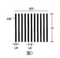
LW‧‧‧線寬LW‧‧‧Line width
LL‧‧‧線之長度LL‧‧‧Line length
LD‧‧‧線間之間隔LD‧‧‧Interval between lines
圖1係用以說明第1實施形態之顯示裝置之文字模糊評價方法之圖。FIG. 1 is a diagram for explaining the method of evaluating the blur of characters of the display device of the first embodiment.
圖2係示意性地表示顯示於圖1之顯示裝置之顯示面之條紋圖案之圖。FIG. 2 is a diagram schematically showing a stripe pattern displayed on the display surface of the display device of FIG. 1.
圖3係一部分之條紋圖案之放大圖。Figure 3 is an enlarged view of a part of the stripe pattern.
圖4係用以說明第2實施形態之光學構件之文字模糊評價方法之圖。Fig. 4 is a diagram for explaining the method of evaluating the character blurring of the optical member of the second embodiment.
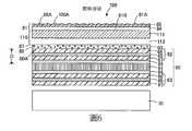
圖5係具備第3實施形態之光學構件之顯示裝置之概略構成圖。Fig. 5 is a schematic configuration diagram of a display device provided with the optical member of the third embodiment.
圖6係具備第3實施形態之另一光學構件之顯示裝置之概略構成圖。Fig. 6 is a schematic configuration diagram of a display device provided with another optical member of the third embodiment.
[第1實施形態][First Embodiment]
以下,一面參照圖式,一面對本發明之第1實施形態之顯示裝置之文字模糊評價方法進行說明。本說明書中之「文字」係指包含平假名、片假名、漢字及字母等用以表示句子或單詞之狹義之文字,且亦包含數字、記號、圖形等之概念。又,於本說明書中,「膜」係以亦包含亦可稱為片材之構件之意義使用。作為一具體例,「防眩膜」亦包含被稱為「防眩片材」等之構件。圖1係用以說明實施形態之顯示裝置之文字模糊評價方法之圖,圖2係示意性地表示顯示於圖1所示之顯示裝置之顯示面之條紋圖案之圖,圖3係一部分之條紋圖案之放大圖。Hereinafter, while referring to the drawings, a description will be given of the method for evaluating the blurring of characters in the display device according to the first embodiment of the present invention. "Text" in this manual refers to narrow-sense texts that include hiragana, katakana, kanji and letters to represent sentences or words, and also include concepts such as numbers, signs, and graphics. In addition, in this specification, "film" is used in the meaning that it also includes a member that can also be called a sheet. As a specific example, "anti-glare film" also includes members called "anti-glare sheet". FIG. 1 is a diagram for explaining the method of evaluating the text blur of the display device of the embodiment, FIG. 2 is a diagram schematically showing the stripe pattern displayed on the display surface of the display device shown in FIG. 1, and FIG. 3 is a part of the stripes An enlarged view of the pattern.
<<<顯示裝置之文字模糊評價方法>>><<<Method of Fuzzy Evaluation of Display Device>>>
本實施形態中所說明之顯示裝置之文字模糊評價方法係對顯示裝置本身之文字模糊程度進行評價之方法。對顯示裝置之文字模糊進行評價時,首先,如圖1所示,準備文字模糊評價裝置10及作為評價對象之顯示裝置20。The text blur evaluation method of the display device explained in this embodiment is based on the display device itself.A method for evaluating the degree of blurriness of body text. When evaluating the blurring of the characters of the display device, first, as shown in FIG. 1, the character blurring
<<文字模糊評價裝置>><<Text Fuzzy Evaluation Device>>
文字模糊評價裝置10具備:攝像裝置11;及處理裝置12,其電性連接於攝像裝置11。The character
<攝像裝置><Camera Device>
攝像裝置11係用以拍攝自顯示裝置20之顯示面20A出射之光者,攝像裝置11配置於顯示裝置20之顯示面20A上。作為攝像裝置11,例如可使用CCD相機(Charge-Coupled Device相機)。The
攝像裝置11與顯示面20A之距離根據攝像裝置之解析度而不同,例如,較佳為設為50mm以上500mm以下。拍攝時,較佳為以下述條紋圖案變得最清晰之方式將攝像裝置11之焦點對準,又,將光圈與適當之部位對準。The distance between the
<處理裝置><Processing device>
處理裝置12以圖像之形式擷取由攝像裝置11拍攝到之光。對於擷取到之圖像,可不進行圖像處理,但於雜訊較多之情形時,例如,較佳為進行低通濾波器處理等圖像處理而進一步減少雜訊。但是,對比度可能會根據圖像處理之條件而變化,故而於進行圖像處理之情形時,較佳為於進行比較之樣本間進行同一處理。The
<<顯示裝置>><<Display device>>
顯示裝置20具備:顯示元件21;及顯示面20A,其位於較顯示元件21更靠觀察者側,且可顯示文字或下述條紋圖案20C~20E。作為顯示元件21,並無特別限定,可列舉液晶顯示元件或有機電致發光元件。液晶顯示元件係於2片玻璃基材間配置液晶層、配向膜、電極層、彩色濾光片等而成者。顯示裝置20可於較顯示元件21更靠觀察者側具備偏光板、光學膜、及/或觸控面板等。The
顯示裝置20之顯示面20A中之白顯示之亮度較佳為400cd/m2以上。又,顯示裝置20之大小例如可為1英吋以上500英吋以下。The brightness of the white display on the
如圖2所示,顯示裝置20係可使由複數個線20B所構成且線20B之線寬LW(參照圖3)不同之2種以上、較佳為3種以上之條紋圖案20C~20E顯示於顯示面20A者。圖2所示之顯示裝置20係可使線寬LW不同之3種條紋圖案20C~20E顯示者。於顯示裝置為平板終端之情形時,例如,可於個人電腦(PC)之顯示面,以所期望之條紋圖案顯示於作為平板終端之顯示裝置之方式製作條紋圖案,將所製作之條紋圖案傳送至作為平板終端之顯示裝置,並藉由應用軟體使條紋圖案顯示於顯示裝置之顯示面。As shown in FIG. 2, the
於顯示裝置20之顯示面20A中,就使條紋圖案20C~20E接近實際之文字之觀點而言,較佳為使線寬LW與構成文字之線之線寬相同或與其相近之像素數之條紋圖案20C~20E分別顯示。通常,顯示裝置中所使用之文字之寬度多數情況下為1~4像素左右,故而構成條紋圖案20C~20E之線20B之線寬LW較佳為1像素以上4像素以下。具體而言,較佳為使線寬為1像素之條紋圖案、線寬為2像素之條紋圖案、線寬為4像素之條紋圖案顯示於顯示裝置20之顯示面20A。In the
構成條紋圖案20C~20E之線20B之個數並無特別限定,就測定精度之觀點而言,較佳為5以上。又,構成條紋圖案20C~20E之線20B之個數可針對每個條紋圖案20C~20E而不同,但就線寬越小之條紋圖案,個數越多之方面而言,較佳為每個條紋圖案20C~20E無面積之差異,故而各條紋圖案20C~20E之面積較佳為大致固定。The number of
條紋圖案20C~20E之線20B之長度LL(參照圖3)並無特別限定,就測定精度及測定之難易度之觀點而言,較佳為0.5cm以上3cm以下。The length LL (refer to FIG. 3) of the
條紋圖案20C~20E之線20B間之間隔LD(參照圖3)並無特別限定,就對於各種文字易於通用性地適用之觀點而言,較佳為與構成條紋圖案20C~20E之線20B之線寬LW相同。例如,於條紋圖案之線之線寬為1像素之情形時,條紋圖案之線間之間隔較佳為1像素,於條紋圖案之線之線寬為2像素之情形時,條紋圖案之線間之間隔較佳為2像素,於條紋圖案之線之線寬為4像素之情形時,條紋圖案之線間之間隔較佳為4像素。The interval LD between the
條紋圖案20C~20E之顏色並無特別限定,就使條紋圖案20C~20E顯示之觀點而言,可想而知,其與條紋圖案20C~20E之背景之顏色不同。例如,於條紋圖案為黑色之情形時,條紋圖案之背景可為白色,又,於條紋圖案為白色之情形時,條紋圖案之背景可為黑色。The color of the
顯示裝置20之用途並無特別限定,例如,可為電視用途、個人電腦用途、智慧型手機用途、平板終端用途、汽車導航裝置等車載用途。尤其是,關於下述對比度之值較大之顯示裝置,其文字模糊程度較小,故而可獲得即便於行駛時亦可瞬時地準確地掌握文字資訊之水準之清晰度。因此,對比度之值較大之顯示裝置適合車載用途。The use of the
準備文字模糊評價裝置10及顯示裝置20之後,以顯示裝置20成為大致水平之方式配置顯示裝置20,又,於顯示裝置20之垂直方向配置攝像裝置11。然後,於在顯示裝置20之顯示面20A顯示有2種以上之條紋圖案20C~20E之狀態下,較佳為於暗室下,首先,以條紋圖案20C位於利用攝像裝置11拍攝到之圖像之大致中央之方式將顯示裝置20之位置對準,並藉由攝像裝置11拍攝自顯示裝置20出射之光。其次,使顯示裝置20大致水平地移動,以條紋圖案20D位於利用攝像裝置11拍攝到之圖像之大致中央之方式將顯示裝置20之位置對準,同樣地,拍攝自顯示裝置20出射之光。進而,使顯示裝置20大致水平地移動,以條紋圖案20E位於利用攝像裝置11拍攝到之圖像之大致中央之方式將顯示裝置20之位置對準,同樣地,拍攝自顯示裝置20出射之光。再者,該拍攝係於使顯示裝置20靜置之狀態下進行。然後,藉由處理裝置12,自拍攝到之光求出橫切各條紋圖案20C~20E之方向之亮度變化,並自亮度變化求出每個條紋圖案20C~20E之對比度,評價文字模糊。本說明書中之「橫切條紋圖案之方向」意指橫切構成條紋圖案之各線之方向,具體而言,例如為沿著圖2之箭頭所示之顯示面20A、且與構成條紋圖案20C~20E之各線20B正交之方向。After preparing the character
對比度可由下述式(1)求出。決定由下述式(1)求出對比度之原因在於,因分子表示亮度變化之大小,分母表示整體之亮度之大小,故可不論整體之亮度之大小地對文字模糊程度進行評價。再者,由下述式(1)求出之對比度意指,對比度之值越大,文字模糊程度越小。The contrast can be calculated by the following formula (1). The reason for determining the contrast obtained from the following formula (1) is that since the numerator represents the magnitude of the brightness change, and the denominator represents the magnitude of the overall brightness, the degree of text blur can be evaluated regardless of the magnitude of the overall brightness. Furthermore, the contrast calculated by the following formula (1) means that the larger the value of the contrast, the smaller the blurriness of characters.
C=(M-m)/(M+m)…(1)C=(M-m)/(M+m)…(1)
式(1)中,C為對比度,M為條紋圖案中之亮度之最大值(最大亮度),m為條紋圖案中之亮度之最小值(最小亮度)。In the formula (1), C is the contrast, M is the maximum value of the brightness in the striped pattern (maximum brightness), and m is the minimum value of the brightness in the striped pattern (minimum brightness).
根據本實施形態,由於使用線寬不同之2種以上之條紋圖案20C~20E,並針對每個條紋圖案20C~20E求出對比度,故而可分別對顯示裝置20中之粗細度不同之2種以上之文字中之文字模糊程度進行評價。即,構成條紋圖案20C~20E之線20B可謂再現了構成文字之線,故而藉由使用線寬LW不同之2種以上之條紋圖案20C~20E,可對粗細度不同之2種以上之文字進行評價。又,使用條紋圖案20C~20E求出之對比度分別表示條紋圖案20C~20E之清晰度,故而使用條紋圖案20C~20E求出之對比度等同於表示了文字之清晰度,即,文字模糊程度。藉此,藉由使用線寬LW不同之2種以上之條紋圖案20C~20E,且針對每個條紋圖案20C~20E求出對比度,可分別對顯示裝置20中之粗細度不同之2種以上之文字中之文字模糊程度進行評價。According to this embodiment, since two or
於存在像素密度彼此相同或同程度之2個以上之顯示裝置之情形時,可藉由利用上述方法分別針對每個條紋圖案求出對比度,並針對每個相同條紋圖案比較對比度,而評價哪一個顯示裝置之文字模糊程度更小或更大。When there are two or more display devices with the same or the same pixel density, the above method can be used to find the contrast for each stripe pattern, and compare the contrast for each same stripe pattern to evaluate which one The text blur degree of the display device is smaller or larger.
[第2實施形態][Second Embodiment]
以下,一面參照圖式,一面對本發明之第2實施形態之光學構件之文字模糊評價方法及光學構件進行說明。圖4係用以說明本實施形態之光學構件之文字模糊評價方法之圖。Hereinafter, with reference to the drawings, a description will be given of the character blur evaluation method and the optical member of the optical member according to the second embodiment of the present invention. Fig. 4 is a diagram for explaining the method for evaluating the blurring of characters of the optical member of the present embodiment.
<<<光學構件之文字模糊評價方法>>><<<Fuzzy Evaluation Method of Optical Components>>>
本實施形態中所說明之光學構件之文字模糊評價方法係評價因光學構件而發生了何種程度之文字模糊之方法。對光學構件之文字模糊進行評價時,首先,如圖4所示,準備文字模糊評價裝置30及作為評價對象之光學構件40,並於文字模糊評價裝置30之顯示裝置20之顯示面20A配置光學構件40。The character blur evaluation method of the optical member explained in this embodiment is a method of evaluating the degree of character blur due to the optical member. When evaluating the character blurring of an optical member, first, as shown in FIG. 4, prepare the character
<<文字模糊評價裝置>><<Text Fuzzy Evaluation Device>>
文字模糊評價裝置30具備:顯示裝置20;攝像裝置11,其配置於顯示裝置20之顯示面20A之上方;及處理裝置12,其電性連接於攝像裝置11。顯示裝置20、攝像裝置11及處理裝置12與第1實施形態中所說明之顯示裝置20、攝像裝置11及處理裝置12同樣,故而省略說明。再者,於第1實施形態中,將顯示裝置20用於對顯示裝置20本身之評價,於本實施形態中,將顯示裝置20用於對光學構件40之評價。The character
<<光學構件>><<Optical Components>>
光學構件意指用於顯示裝置之具有某些功能之透光性之構件。作為光學構件,並無特別限定,例如,可列舉:防眩膜、抗反射膜、硬塗膜、及光擴散膜等光學膜、前面板、或將其等組合而成之構件等。The optical member means a translucent member with certain functions used in a display device. The optical member is not particularly limited, and examples thereof include optical films such as anti-glare films, anti-reflection films, hard coat films, and light diffusion films, front panels, or a combination of these and the like.
光學構件之大小並無特別限制,例如,根據智慧型手機、平板終端、個人電腦(PC)、可佩戴式終端、數位標牌、電視等圖像顯示裝置之顯示面之大小而適當決定。具體而言,光學構件之大小例如可為1英吋以上500英吋以下。The size of the optical component is not particularly limited. For example, it may be appropriately determined according to the size of the display surface of an image display device such as a smart phone, a tablet terminal, a personal computer (PC), a wearable terminal, a digital sign, a TV, and so on. Specifically, the size of the optical member can be, for example, 1 inch or more and 500 inches or less.
作為光學構件40,並無特別限定,就可抑制眩光,且以極高水準抑制文字模糊之觀點而言,較佳為具備:防眩膜41,其具有構成光學構件40之觀察者側之表面40A之凹凸面41A;中間構件42,其配置於防眩膜41中之與凹凸面41A為相反之側之面41B側;及光擴散膜43,其配置於較中間構件42更靠顯示元件21側。The
<防眩膜><Anti-glare film>
防眩膜41例如具備:透光性基材44;及防眩層45,其配置於透光性基材44之一面側,且具有成為凹凸面41A之凹凸面45A。The
作為透光性基材44,只要具有透光性,則並無特別限定,例如,可列舉:醯化纖維素基材、環烯烴聚合物基材、聚碳酸酯基材、丙烯酸酯系聚合物基材、聚酯基材、或玻璃基材。The light-transmitting
透光性基材44之厚度並無特別限定,可設為5μm以上1000μm以下。透光性基材44之厚度意指使用厚度測定裝置(製品名「Digimatic Indicator IDF-130」,Mitutoyo公司製造)測定透光性基材44之10個點之厚度而得之其平均值。透光性基材44之厚度之下限就處理性等觀點而言,較佳為15μm以上,更佳為25μm以上。透光性基材44之厚度之上限就薄膜化之觀點而言,較佳為80μm以下。The thickness of the
防眩層45係發揮防眩性之層。防眩層45亦可為發揮防眩性,並且發揮其他功能者。具體而言,防眩層45亦可為發揮防眩性,並且例如發揮硬塗性、抗反射性、抗靜電性、或防污性等功能之層。The
防眩層45之厚度並無特別限定,可設為1μm以上20μm以下。防眩層45之厚度係由穿透式電子顯微鏡(TEM)或掃描穿透式電子顯微鏡(STEM)之圖像,使用圖像處理軟體而測得之值。此處,防眩層之表面為凹凸面,故而厚度會根據位置之不同而不同,但上述「防眩層之厚度」意指測定防眩層之10個點之厚度而得之其平均值。The thickness of the
作為防眩層45之凹凸面45A之形成方法,例如,可列舉:(A)使用包含硬化後成為黏合劑樹脂之聚合性化合物及粒子之防眩層用組成物形成凹凸面之方法、(B)藉由使用金屬模具之轉印方法而形成凹凸面之方法、(C)藉由噴砂使防眩層之表面變得粗糙藉此形成凹凸面之方法、或(D)藉由利用壓紋輥對防眩層之表面賦予凹凸而形成凹凸面之方法等。其等之中,就製造容易之方面而言,較佳為上述(A)之方法。於防眩層由上述(A)之方法形成之情形時,防眩層包含黏合劑樹脂及粒子。As a method of forming the
<中間構件><Intermediate member>
中間構件42係配置於防眩膜41與光擴散膜43之間之構件,例如,可列舉:前面板、觸控面板、空氣層(氣隙)、接合樹脂層或其等之組合。圖4所示之中間構件42為前面板。藉由使中間構件42為前面板,可提高耐久性及/或設計性。The
中間構件42之厚度較佳為0.1mm以上5mm以下。若中間構件42之厚度未達0.1mm,則於中間構件42為前面板之情形時,有無法確保光學構件之耐久性之虞,又,若超過5mm,則有視認性變差之虞。中間構件42之厚度係使用掃描式電子顯微鏡(SEM),拍攝中間構件42之剖面,於該剖面之圖像中測定中間構件之10個點之厚度,並設為其平均值。中間構件42之厚度之下限更佳為0.5mm以上,又,上限更佳為3mm以下。The thickness of the
於中間構件42為前面板之情形時,作為構成前面板之材料,可列舉:玻璃、聚甲基丙烯酸甲酯、聚碳酸酯、聚醯亞胺等。其等之中,就抗環境性之觀點而言,較佳為玻璃。When the
<光擴散膜><Light diffusion film>
光擴散膜43係用以使入射之光擴散者。作為光擴散膜43,並無特別限定,例如可為包含光擴散粒子之膜或包含凸狀構造體之膜。The
圖4所示之光擴散膜43例如包含透光性基材46、及分散於透光性基材46中之光擴散粒子47,但並不限定於該構造,亦可為具備透光性基材、以及設置於透光性基材之一面且包含黏合劑樹脂及分散於黏合劑樹脂中之光擴散粒子之光擴散層者。光擴散膜43可藉由於在構成透光性基材46之樹脂中添加了光擴散粒子47之狀態下擠出而獲得。又,具備光擴散層之光擴散膜可藉由將包含硬化後成為黏合劑樹脂之聚合性化合物及光擴散粒子之光擴散層用組成物塗佈於透光性基材上,並使其硬化而獲得。The
光擴散膜43之厚度較佳為20μm以上300μm以下。若光擴散膜43之厚度未達20μm,則有光擴散性不充分之虞,又,若超過300μm,則有操作性變差之虞。光擴散膜43之厚度係使用掃描式電子顯微鏡(SEM),拍攝光擴散膜43之剖面,於該剖面之圖像中測定光擴散膜43之10個部位之厚度,並設為該10個部位之厚度之平均值。光擴散膜43之厚度之下限更佳為50μm以上,又,上限更佳為200μm以下。The thickness of the
(透光性基材)(Translucent substrate)
作為透光性基材46,並無特別限定,例如,可使用與透光性基材44同樣者。The
(光擴散粒子)(Light diffusion particles)
光擴散粒子47係用以使入射至光擴散膜43之光擴散之粒子。光擴散粒子47之平均粒徑例如較佳為1μm以上30μm以下。若光擴散粒子47之平均粒徑未達1μm,則有無法獲得充分之光擴散性之虞,又,若超過30μm,則有光擴散性變得不均勻之虞。光擴散粒子之平均粒徑可設為藉由光學顯微鏡之透過觀察、或利用掃描式電子顯微鏡之觀察而測得之20個粒子之直徑之平均值而求出。光擴散粒子47之平均粒徑之下限更佳為3μm以上,又,上限更佳為20μm以下。The light diffusion particles 47 are particles for diffusing the light incident on the
透光性基材46與光擴散粒子47之折射率差之絕對值較佳為0.01以上0.3以下。若未達0.01,則光擴散膜中之光擴散性會變得不充分,又,若超過0.3,則存在光擴散膜之透過率降低之情況。關於透光性基材46之折射率與光擴散粒子47之折射率,可為任一者較大。此處,作為包含於光擴散膜之前之光擴散粒子之折射率之測定方法,例如,可藉由貝克(Becke)法、最小偏角法、偏角解析、模式線(mode-line)法、橢圓偏光法等而進行測定。作為光擴散膜中之透光性基材、光擴散粒子之折射率之測定方法,例如,可對自光擴散膜中以某種形式取出光擴散粒子之碎片、或透光性基材之碎片而成者使用貝克法。除此以外,亦可使用相位偏移雷射干涉顯微鏡(FK光學研究所製造之相位偏移雷射干涉顯微鏡或溝尻光學工業所製造之二光束干涉顯微鏡等)測定透光性基材與光擴散粒子之折射率差。透光性基材46與光擴散粒子47之折射率差之絕對值之下限更佳為0.05以上,上限較佳為0.2以下。The absolute value of the difference in refractive index between the
光擴散粒子47可為由有機材料所構成之粒子或由無機材料所構成之粒子。作為構成光擴散粒子47之有機材料,並無特別限定,例如,可列舉:聚酯、聚苯乙烯、三聚氰胺樹脂、(甲基)丙烯酸樹脂、丙烯酸-苯乙烯共聚物樹脂、矽酮樹脂、苯胍胺樹脂、苯胍胺-甲醛縮合樹脂、聚碳酸酯、聚乙烯、聚烯烴等。其中,較佳地使用交聯丙烯酸系樹脂。又,作為構成上述光擴散粒子之無機材料,並無特別限定,例如,可列舉:二氧化矽、氧化鋁、氧化鈦、氧化錫、摻銻氧化錫(ATO)、氧化鋅微粒子等無機氧化物等。其中,較佳地使用二氧化矽及/或氧化鋁。The light diffusion particles 47 may be particles composed of organic materials or particles composed of inorganic materials. The organic material constituting the light diffusing particles 47 is not particularly limited, and examples include polyester, polystyrene, melamine resin, (meth)acrylic resin, and acrylic-benzene.Ethylene copolymer resin, silicone resin, benzoguanamine resin, benzoguanamine-formaldehyde condensation resin, polycarbonate, polyethylene, polyolefin, etc. Among them, crosslinked acrylic resins are preferably used. In addition, the inorganic material constituting the light diffusion particles is not particularly limited, and examples include inorganic oxides such as silicon dioxide, aluminum oxide, titanium oxide, tin oxide, antimony-doped tin oxide (ATO), and zinc oxide fine particles. Wait. Among them, silicon dioxide and/or aluminum oxide are preferably used.
準備文字模糊評價裝置30及光學構件40之後,以顯示裝置20及光學構件40成為大致水平之方式於顯示裝置20之顯示面20A配置光學構件40,又,於顯示裝置20及光學構件40之垂直方向配置攝像裝置11。然後,於在顯示裝置20之顯示面20A顯示有2種以上之條紋圖案20C~20E之狀態下,較佳為於暗室下,以條紋圖案20C位於利用攝像裝置11拍攝到之圖像之大致中央之方式將顯示裝置20及光學構件40之位置對準,並藉由攝像裝置11拍攝自顯示裝置20出射且透過光學構件40之光。其次,使顯示裝置20大致水平地移動,以條紋圖案20D位於利用攝像裝置11拍攝到之圖像之大致中央之方式將顯示裝置20及光學構件40之位置對準,同樣地,拍攝自顯示裝置20出射且透過光學構件40之光。進而,使顯示裝置20及光學構件40大致水平地移動,以條紋圖案20E位於利用攝像裝置11拍攝到之圖像之大致中央之方式將顯示裝置20及光學構件40之位置對準,同樣地,拍攝自顯示裝置20出射且透過光學構件40之光。再者,拍攝係於使顯示裝置20及光學構件40靜置之狀態下進行。然後,藉由處理裝置12,自拍攝到之光求出橫切各條紋圖案20C~20E之方向之亮度變化,並自亮度變化求出每個條紋圖案20C~20E之對比度,評價文字模糊。After preparing the character
對比度與上述同樣地,可由下述式(1)求出。The contrast ratio can be calculated by the following formula (1) in the same manner as described above.
C=(M-m)/(M+m)…(1)C=(M-m)/(M+m)…(1)
式(1)中,C為對比度,M為條紋圖案中之亮度之最大值(最大亮度),m為條紋圖案中之亮度之最小值(最小亮度)。In the formula (1), C is the contrast, M is the maximum value of the brightness in the striped pattern (maximum brightness), and m is the minimum value of the brightness in the striped pattern (minimum brightness).
根據本實施形態,由於使用了線寬不同之2種以上之條紋圖案,並針對每個條紋圖案求出了對比度,故而可分別對光學構件中之粗細度不同之2種以上之文字中之文字模糊程度進行評價。即,基於與第1實施形態同樣之理由,而可分別對粗細度不同之2種以上之文字中之文字模糊程度進行評價,但於本實施形態中,於顯示裝置20之顯示面20A上配置有光學構件40。此處,若亦於在顯示裝置20之顯示面20A上未配置光學構件40之狀態下求出對比度,並將在顯示裝置20之顯示面20A上配置光學構件40之狀態下求出之對比度、與在顯示裝置20之顯示面20A上未配置光學構件40之狀態下求出之對比度進行比較,則可分別評價因配置光學構件40而於粗細度不同之2種以上之文字中產生了何種程度之文字模糊。又,若亦於在顯示裝置20之顯示面20A上配置與光學構件40不同之光學構件之狀態下求出對比度,並將在顯示裝置20之顯示面20A上配置光學構件40之狀態下求出之對比度、與在顯示裝置20之顯示面20A上配置與光學構件40不同之光學構件之狀態下求出之對比度進行比較,則可分別評價出,於光學構件40,及與光學構件40相異之光學構件之何者在粗細度相異之2種以上之文字中,文字模糊程度更小或更大。According to this embodiment, since two or more types of stripe patterns with different line widths are used, and the contrast is calculated for each stripe pattern, it is possible to separately analyze the characters of two or more types of characters with different thicknesses in the optical member. The degree of ambiguity is evaluated. That is, based on the same reason as the first embodiment, it is possible to evaluate the degree of blurring of two or more types of characters with different thicknesses. However, in this embodiment, it is arranged on the
關於上述在顯示裝置20之顯示面20A上未配置光學構件40之狀態下之對比度,除了不在顯示裝置20之顯示面20A上配置光學構件40以外,利用與在顯示裝置20之顯示面20A上配置光學構件40之狀態下求出之對比度同樣之方法求出。於此情形時,由於在顯示裝置20之顯示面20A上未配置光學構件40,因而理所當然,由攝像裝置11拍攝到之光係直接拍攝了自顯示裝置出射之光。又,關於上述在顯示裝置20之顯示面20A上配置與光學構件40不同之光學構件之狀態下之對比度,除了在顯示裝置20之顯示面20A上配置與光學構件40不同之光學構件以外,利用與在顯示裝置20之顯示面20A上配置光學構件40之狀態下求出之對比度同樣之方法求出。Regarding the above-mentioned contrast ratio in the state where the
光學構件40之用途並無特別限定,例如,可為電視用途、個人電腦用途、智慧型手機用途、平板終端用途、汽車導航裝置等車載用途。尤其是,關於對比度之值較大之光學構件,其文字模糊之程度較小,故而可獲得即便於行駛時亦可瞬時地準確地掌握文字資訊之水準之清晰度。因此,對比度之值極其大之光學構件適合車載用途。The use of the
於將顯示裝置用於車載用途之情形時,若有外界光之射入,則駕駛員因外界光之射入而變得難以識別道路等之圖形資訊或文字資訊,故而需要極力排除外界光。又,於將顯示裝置用於車載用途之情形時,藉由食指而按壓顯示面,故而需要充分之強度。於本實施形態中,由於使用了具備防眩膜41及中間構件42之光學構件40,故而於中間構件42為前面板之情形時,可一面極力排除外界光,一面獲得充分之強度。因此,光學構件40尤其適合車載用途。When the display device is used for in-vehicle use, if the external light enters, it will be difficult for the driver to recognize the graphic information or text information of the road due to the external light. Therefore, it is necessary to eliminate the external light as much as possible. In addition, when the display device is used for in-vehicle use, the index finger presses the display surface, so sufficient strength is required. In this embodiment, since the
於光學構件之中,有亮黑感或漆黑感等黑色再現性良好者,但光學構件中之黑色再現性良好之情況、與文字模糊程度較小之情況完全不同,故而即便於黑色再現性良好之情形時,文字模糊程度亦未必較小。Among the optical components, there are those with good black reproducibility such as bright black feeling or pitch black feeling, but the case of good black reproducibility in optical components is completely different from the case where the degree of blurring of characters is small, so even in black, the reproducibility is good In this case, the degree of text blur may not be small.
[第3實施形態][Third Embodiment]
以下,一面參照圖式,一面對本發明之第3實施形態之光學構件及顯示裝置進行說明。圖5係具備本實施形態之光學構件之顯示裝置之概略構成圖,圖6係具備本實施形態之另一光學構件之顯示裝置之概略構成圖。Hereinafter, the optical member and the display device of the third embodiment of the present invention will be described with reference to the drawings. FIG. 5 is a schematic configuration diagram of a display device provided with the optical member of this embodiment, and FIG. 6 is a schematic configuration diagram of a display device provided with another optical member of this embodiment.
<<<光學構件及顯示裝置>>><<<Optical components and display devices>>>
如圖5所示,顯示裝置50主要具備:顯示面板60;背光裝置70,其配置於顯示面板60之背面側;及光學構件80,其配置於顯示面板60之觀察者側。顯示裝置50只要具備顯示面板60及光學構件80即可,除此以外,亦可於顯示面板60與光學構件80之間具備觸控面板。藉由具備觸控面板,可獲得具有觸控面板功能之顯示裝置。又,於本實施形態中,由於顯示面板60為液晶顯示面板,故而顯示裝置50具備背光裝置70,但根據顯示面板(顯示元件)之種類之不同,亦可具備背光裝置70。顯示裝置50之大小例如可為1英吋以上500英吋以下。As shown in FIG. 5, the
<<顯示面板>><<Display Panel>>
如圖5所示,顯示面板60具備顯示元件61。顯示元件61為液晶顯示元件。但是,顯示元件並不限定於液晶顯示元件,例如,可為有機電致發光顯示元件等。液晶顯示元件係於2片玻璃基材間配置液晶層、配向膜、電極層、彩色濾光片等而成者。As shown in FIG. 5, the
顯示面板60具備分別配置於顯示元件61之觀察者側及背光裝置70側之偏光板62、63,顯示元件61與偏光板62、63經由感壓接著劑(PSA)等透明黏著層64而被一體化。The
偏光板62、63具備:偏光元件65;保護膜66,其貼附於偏光元件65之一面;及保護膜67,其貼附於偏光元件65之另一面。保護膜66、67係用以保護偏光元件65者,由三乙醯纖維素膜(TAC膜)等透光性基材所構成。再者,偏光板62之保護膜66亦可於較透光性基材更靠觀察者側具備硬塗層等功能層。The
作為偏光元件65,例如,可列舉:藉由碘等而染色並延伸之聚乙烯醇膜、聚乙烯醇縮甲醛膜、聚乙烯醇縮乙醛膜、乙烯-乙酸乙烯酯共聚物系皂化膜等。於積層偏光元件65及保護膜66、67時,較佳為預先對保護膜66、67實施皂化處理。藉由對保護膜66、67實施皂化處理,其與偏光元件65之接著性變好。Examples of the
<<背光裝置>><<Backlight device>>
背光裝置70係自顯示面板60之背面側對顯示面板60進行照明者。作為背光裝置70,可使用習知之背光裝置,又,背光裝置70可為邊緣照明型或正下方型之背光裝置之任一者。The
<<光學構件>><<Optical Components>>
光學構件80具備:防眩膜81,其具有構成光學構件80之觀察者側之表面80A之凹凸面81A;中間構件82,其配置於防眩膜81中之與凹凸面81A為相反之側之面81B側;及光擴散膜83,其配置於較中間構件82更靠顯示面板60側。於光學構件80搭載於顯示裝置50之狀態下,防眩膜81之凹凸面81A構成顯示裝置50之觀察者側之顯示面50A,中間構件82及光擴散膜83配置於顯示面板60與防眩膜81之間。光學構件80可相對於顯示面板60利用接著劑等進行固定,亦可不進行固定。The
<防眩膜><Anti-glare film>
防眩膜81例如具備:透光性基材84;及防眩層85,其配置於透光性基材84之觀察者側,且具有成為凹凸面81A之凹凸面85A。The
防眩層85係發揮防眩性之層。防眩層85亦可為發揮防眩性,並且發揮其他功能者。具體而言,防眩層85亦可為發揮防眩性,並且例如發揮硬塗性、抗反射性、抗靜電性、或防污性等功能之層。The
於防眩膜81之凹凸面81A中,構成凹凸面81A之凹凸之平均間隔Sm較佳為0.050mm以上0.300mm以下。若Sm未達0.050mm,則有對比度較差之虞,又,若Sm超過0.300mm,則有無法抑制眩光之虞。Sm更佳為0.060mm以上0.200mm以下。於防眩膜81之凹凸面81A中,構成凹凸面81A之凹凸之平均傾斜角θa較佳為0.1°以上4.0°以下。若θa未達0.1°,則有防眩性變得不充分之虞,又,若θa超過4.0°,則有對比度較差之虞。θa更佳為0.5°以上2.0°以下。In the
於防眩膜81之凹凸面81A中,構成凹凸面81A之凹凸之算術平均粗糙度Ra較佳為0.05μm以上0.40μm以下。若Ra未達0.05μm,則有防眩性變得不充分之虞,又,若Ra超過0.40μm,則有對比度較差之虞。Ra更佳為0.10μm以上0.25μm以下。於防眩膜81之凹凸面81A中,構成凹凸面85A之凹凸之最大高度粗糙度Ry較佳為1.0μm以上4.0μm以下。若Ry未達1.0μm,則有防眩性變得不充分之虞,又,若Ry超過4.0μm,則有對比度較差之虞。Ry更佳為1.5μm以上3.5μm以下。於防眩膜81之凹凸面81A中,構成凹凸面81A之凹凸之10個點平均粗糙度Rz較佳為0.30μm以上2.50μm以下。若Rz未達0.30μm,則有防眩性變得不充分之虞,又,若Rz超過2.50μm,則有對比度較差之虞。Rz更佳為0.50μm以上1.80μm以下。In the
上述「Sm」、「Ra」、「Ry」及「Rz」之定義係依據JIS B0601:1994者。「θa」之定義係依據作為表面粗糙度測定器之SE-3400(小阪研究所製造)之操作說明書(1995.07.20改訂)者。具體而言,θa用下述式(2)表示。The above definitions of "Sm", "Ra", "Ry" and "Rz" are based on JIS B0601:1994. The definition of "θa" is based on the SE-3400 (manufactured by Kosaka Laboratory) as a surface roughness tester (revised on July 20, 1995). Specifically, θa is represented by the following formula (2).
θa=tam-1△a…(2)θa=tam-1 △a…(2)
式(2)中,△a係以縱橫比率表示傾斜者,係各凹凸之極小部與極大部之差(相當於各凸部之高度)之總和除以基準長度而得之值。In formula (2), Δa expresses the inclination in terms of the aspect ratio, and is the value obtained by dividing the sum of the difference between the minimum portion and the maximum portion of each concavity and convexity (equivalent to the height of each convex portion) by the reference length.
Sm、Ra、Ry、Rz及θa例如均可使用SURFCORDER SE-3400、SE-3500、或SE-500(均為小阪研究所製造)進行測定。此處,即便於無法直接測定θa之情形時,於可測定△a之情形時,由於θa與△a有上述式(2)所示之關係,故而可測定△a,並自所測得之△a求出θa。再者,測定Sm等時之截止波長均設定為0.8mm。Sm, Ra, Ry, Rz, and θa can be measured using, for example, SURFCORDER SE-3400, SE-3500, or SE-500 (all manufactured by Kosaka Laboratories). Here, even when θa cannot be measured directly, when Δa can be measured, since θa and Δa have the relationship shown in the above formula (2), Δa can be measured and obtained from the measurement △a Find θa. Furthermore, the cut-off wavelengths when measuring Sm etc. are all set to 0.8mm.
透光性基材84及防眩層85與透光性基材44及防眩層45同樣,故而此處省略說明。The
<中間構件><Intermediate member>
中間構件82與中間構件42同樣,故而除了下述以外,省略說明。The
中間構件82之霧度值就除了防眩膜81或光擴散膜83以外較佳為透明之方面而言,較佳為0.8%以下。霧度值係依據JIS K7136:2000,使用霧度計(製品名「HM-150」,村上色彩技術研究所製造),對裁切為縱10cm×橫10cm之大小之中間構件82進行3次測定,並設為進行3次測定而得之值之算術平均值。The haze value of the
中間構件82之全光線透過率就顯示面之視認性提高之方面而言,較佳為80%以上。全光線透過率係依據JIS K7361-1:1997,使用霧度計(製品名「HM-150」,村上色彩技術研究所製造),對剪切為縱10cm×橫10cm之大小之中間構件82進行3次測定,並設為進行3次測定而得之值之算術平均值。The total light transmittance of the
<光擴散膜><Light diffusion film>
光擴散膜83係用以使入射之光擴散者。作為光擴散膜83,並無特別限定,例如可為包含光擴散粒子之膜或包含凸狀構造體之膜。The
顯示元件61與光擴散膜83之間之距離D就抑制文字模糊之觀點而言,較佳為1mm以下,更佳為0.5mm以下。顯示元件61與光擴散膜83之間之距離D意指自顯示元件61中之光擴散膜83側之面(例如,構成顯示元件61之光擴散膜83側之玻璃板中之光擴散膜83側之表面)至光擴散膜83中之顯示元件61側之面之距離。顯示元件61與光擴散膜83之間之距離D係測定10個部位之顯示元件61與光擴散膜83之間之距離,並設為該10個部位之距離之平均值。The distance D between the
光擴散膜83與光擴散膜43同樣。因此,光擴散膜83例如包含透光性基材86、及分散於透光性基材86中之光擴散粒子87。The
光擴散膜83之霧度值就抑制眩光之觀點而言,較佳為50%以上,更佳為70%以上,進而較佳為90%以上,就抑制文字模糊之觀點而言,較佳為99%以下,更佳為95%以下,進而較佳為90%以下。光擴散膜83之霧度值可藉由與中間構件82之霧度值同樣之方法而進行測定。From the viewpoint of suppressing glare, the haze value of the
(透光性基材及光擴散粒子)(Translucent substrate and light diffusion particles)
透光性基材86及光擴散粒子87與透光性基材46及光擴散粒子47同樣,故而此處省略說明。The light-transmitting base material 86 and the light-diffusing
<<<其他顯示裝置>>><<<Other display devices>>>
顯示裝置50具備光學構件80,但作為顯示裝置,亦可為如圖6所示之顯示裝置100。再者,於圖6中,附帶有與圖5相同之符號之構件意指與圖5所示之構件相同之構件,故而此處省略說明。The
顯示裝置100具備:防眩膜81,其配置於顯示面板60之觀察者側,且具有構成顯示裝置100之觀察者側之顯示面100A之凹凸面81A;中間構件110,其配置於顯示面板60與防眩膜81之間;及光擴散膜83,其配置於顯示面板60與防眩膜81之間,且配置於較中間構件110更靠顯示面板60側。The
<<中間構件>><<Intermediate member>>
中間構件110由觸控面板111、及位於較觸控面板111更靠顯示面板60側之空氣層112所構成。藉由中間構件110具備觸控面板111,可對顯示裝置100賦予觸控面板功能。作為觸控面板111,可使用習知之觸控面板,又,亦可具備前面板。空氣層112之厚度較佳為0.1mm以上3.0mm以下。只要空氣層112之厚度為0.1mm以上,則可抑制因觸控面板111與光擴散膜83部分地接觸而產生之浮水印,又,只要為3.0mm以下,則可抑制顯示裝置100之厚度變厚。空氣層112之厚度係隨機地測定10個部位之空氣層112之厚度,並設為其平均值。The
根據本實施形態,由於光學構件80或顯示裝置100具備光擴散膜83,故而可抑制因配置防眩膜81而產生之眩光。又,對於因配置光擴散膜而產生之文字模糊之程度,本發明人等進行了努力研究,結果發現文字模糊程度根據文字之粗細度不同而不同,又,依賴於自顯示元件至光擴散膜之距離,具體而言,於自顯示元件至光擴散膜之距離較大之情形時,與自顯示元件至光擴散膜之距離較小之情形相比,文字模糊程度更大。又另一方面發現,眩光不依賴於自顯示元件至光擴散膜之距離。根據本實施形態,由於光擴散膜83配置於較中間構件82、110更靠顯示面板60側,故而與於中間構件與防眩膜之間配置光擴散膜之情形相比,自顯示元件至光擴散膜之距離更小。藉此,可在不依賴於顯示於顯示面板60之顯示面60A之文字之粗細度之情況下使文字模糊程度變得極其小,故而可一面抑制眩光,一面不論文字之粗細度地抑制文字模糊。According to this embodiment, since the
顯示裝置50、100或光學構件80之用途並無特別限定,例如可為電視用途、個人電腦用途、智慧型手機用途、平板終端用途、汽車導航裝置等車載用途。尤其是,關於顯示裝置50、100或光學構件80,其文字模糊程度較小,故而可獲得即便於行駛時亦可瞬時地準確地掌握文字資訊之水準之清晰度。因此,顯示裝置50、100或光學構件80適合車載用途。The use of the
於將顯示裝置用於車載用途之情形時,若有外界光之射入,則駕駛員因外界光之射入而變得難以識別道路等之圖形資訊或文字資訊,故而需要極力排除外界光。又,於將顯示裝置用於車載用途之情形時,藉由食指而按壓顯示面,故而需要充分之強度。於本實施形態中,由於使用了具備防眩膜81及中間構件82之光學構件80,且中間構件82為前面板,故而可一面極力排除外界光,一面獲得充分之強度。因此,光學構件80尤其適合車載用途。When the display device is used for in-vehicle use, if the external light enters, it will be difficult for the driver to recognize the graphic information or text information of the road due to the external light. Therefore, it is necessary to eliminate the external light as much as possible. In addition, when the display device is used for in-vehicle use, the index finger presses the display surface, so sufficient strength is required. In this embodiment, since the
顯示裝置50、100及光學構件80之文字模糊程度可藉由目視而進行評價,就可準確地進行評價之觀點而言,較佳為分別藉由以下之方法而進行評價。再者,以下,對評價光學構件80及顯示裝置50之文字模糊之方法進行說明,但顯示裝置100之文字模糊亦可藉由同樣之方法進行評價。The degree of blurring of the characters of the
<<光學構件之文字模糊評價方法>><<The fuzzy evaluation method of optical components>>
光學構件80之文字模糊可使用與第2實施形態中所說明之文字模糊評價裝置30同樣之文字模糊評價裝置,並藉由與第2實施形態同樣之方法進行評價。具體而言,準備與文字模糊評價裝置30同樣之文字模糊評價裝置、及光學構件80。文字模糊評價裝置係與文字模糊評價裝置同樣之構成,故而具備如下裝置:顯示裝置,其具備可顯示線寬不同之2種以上之條紋圖案之顯示面;攝像裝置,其配置於顯示裝置之顯示面之上方;及處理裝置,其電性連接於攝像裝置。再者,顯示裝置、攝像裝置、及處理裝置與顯示裝置20、攝像裝置11、處理裝置12同樣,又,顯示於顯示裝置之顯示面之條紋圖案亦與條紋圖案20C~20E同樣,故而此處亦省略說明。然後,以文字模糊評價裝置之顯示裝置及光學構件80成為大致水平之方式於顯示裝置及顯示裝置之顯示面配置光學構件80,又,於顯示裝置及光學構件80之垂直方向配置攝像裝置。再者,光學構件80係以光擴散膜83成為顯示裝置之顯示面側之方式配置。然後,於在顯示裝置之顯示面顯示有線寬不同之2種以上之條紋圖案之狀態下,較佳為於暗室下,以1個條紋圖案位於利用攝像裝置拍攝到之圖像之大致中央之方式將顯示裝置及光學構件80之位置對準,並藉由攝像裝置拍攝自顯示裝置出射且透過光學構件80之光。其次,使顯示裝置大致水平地移動,以其他條紋圖案位於利用攝像裝置拍攝到之圖像之大致中央之方式將顯示裝置及光學構件80之位置對準,同樣地,拍攝自顯示裝置出射且透過光學構件80之光。拍攝係於使顯示裝置及光學構件80靜置之狀態下進行。然後,藉由處理裝置,自拍攝到之光求出橫切各條紋圖案之方向之亮度變化,並自亮度變化求出每個條紋圖案之對比度,評價文字模糊。The character blur of the
根據該評價方法,由於使用了線寬不同之2種以上之條紋圖案,並針對每個條紋圖案求出了對比度,故而可分別對光學構件80中之粗細度不同之2種以上之文字中之文字模糊程度進行評價。並且,若亦於在顯示裝置之顯示面上未配置光學構件80之狀態下求出對比度,並將在顯示裝置之顯示面上配置光學構件80之狀態下求出之對比度、與在顯示裝置之顯示面上未配置光學構件80之狀態下求出之對比度進行比較,則可分別評價因配置光學構件80而於粗細度不同之2種以上之文字中產生了何種程度之文字模糊。又,若亦於在顯示裝置之顯示面上配置與光學構件80不同之光學構件(例如,於防眩膜與中間構件之間配置有光擴散膜之光學構件)之狀態下求出對比度,並將在顯示裝置之顯示面上配置光學構件80之狀態下求出之對比度、與在顯示裝置之顯示面上配置與光學構件80不同之光學構件之狀態下求出之對比度進行比較,則可分別評價光學構件80同與光學構件80不同之光學構件之哪一者於粗細度不同之2種以上之文字中文字模糊程度更小或更大。According to this evaluation method, since two or more types of stripe patterns with different line widths are used, and the contrast is calculated for each stripe pattern, it is possible to separately compare two or more types of characters with different thicknesses in the
<<顯示裝置之文字模糊評價方法>><<Fuzzy Evaluation Method of Display Device>>
於上文對光學構件80之文字模糊進行了評價,但亦可對具備光學構件80之顯示裝置50之文字模糊進行評價。顯示裝置50之文字模糊可使用與第1實施形態中所說明之文字模糊評價裝置10同樣之文字模糊評價裝置,並藉由與第1實施形態同樣之方法而進行評價,故而此處省略說明。The character blur of the
於本實施形態中,由於亦使用了線寬不同之2種以上之條紋圖案,並針對每個條紋圖案求出了對比度,故而基於與第1實施形態及第2實施形態中所說明之理由同樣之理由,而可分別對光學構件80及顯示裝置50中之粗細度不同之2種以上之文字中之文字模糊程度進行評價。In this embodiment, two or more stripe patterns with different line widths are also used, and the contrast is calculated for each stripe pattern. Therefore, it is based on the same reason as explained in the first embodiment and the second embodiment. The reason for this is to evaluate the degree of blurring of characters in two or more types of characters with different thicknesses in the
[實施例][Example]
為了對本發明詳細地進行說明,以下,列舉實施例進行說明,但本發明並不限定於該等記載。再者,下述評價或測定係於至少藉由目視而無異常之部位(無較大之異物、擦傷、污垢或褶皺等之部位)進行。In order to describe the present invention in detail, examples are given below for description, but the present invention is not limited to these descriptions. In addition, the following evaluation or measurement is performed at a site where there is no abnormality at least by visual inspection (a site free from large foreign matter, scratches, dirt, wrinkles, etc.).
<<實施例A>><<Example A>>
<防眩層用組成物之製備><Preparation of composition for anti-glare layer>
首先,以成為如下所示之組成之方式調配各成分,而獲得防眩層用組成物1。First, each component is mixed so that it may become a composition shown below, and the composition 1 for anti-glare layer was obtained.
(防眩層用組成物1)(Composition 1 for anti-glare layer)
‧多官能丙烯酸酯單體:80質量份‧Multifunctional acrylate monomer: 80 parts by mass
‧光聚合起始劑:5質量份‧Photopolymerization initiator: 5 parts by mass
‧矽酮系調平劑:0.1質量份‧Silicone-based leveling agent: 0.1 parts by mass
‧球狀聚丙烯酸-苯乙烯粒子(平均粒徑3.5μm,折射率1.52):12質量份‧Spherical polyacrylic acid-styrene particles (average particle size 3.5μm, refractive index 1.52): 12 parts by mass
‧反應性官能基導入二氧化矽超微粒子(固形物成分30%,溶劑(甲基異丁基酮)):120質量份‧Introduction of reactive functional groups into ultrafine silica particles (
‧甲苯:135質量份‧Toluene: 135 parts by mass
<光擴散膜之製備><Preparation of Light Diffusion Film>
以成為如下所示之組成之方式調配各成分,而獲得光擴散膜用組成物1。Each component was mixed so that it might become a composition shown below, and the composition 1 for light-diffusion films was obtained.
(光擴散膜用組成物1)(Composition 1 for light diffusion film)
‧丙烯酸多元醇:80質量份‧Acrylic polyol: 80 parts by mass
‧異氰酸酯系硬化劑:16質量份‧Isocyanate hardener: 16 parts by mass
‧聚甲基丙烯酸甲酯粒子(平均粒徑10μm):100質量份‧Polymethyl methacrylate particles (average particle size 10μm): 100 parts by mass
‧乙酸丁酯:100質量份‧Butyl acetate: 100 parts by mass
‧甲基乙基酮:100質量份‧Methyl ethyl ketone: 100 parts by mass
<樣本1><Sample 1>
準備作為透光性基材之厚度60μm之三乙醯纖維素樹脂膜(Fuji Film公司製造,TD60UL),將防眩層用組成物1塗佈於三乙醯纖維素樹脂膜之單面,而形成塗膜。繼而,對於所形成之塗膜,以0.2m/s之流速使50℃之乾燥空氣流通15秒鐘之後,進而,以10m/s之流速使70℃之乾燥空氣流通30秒鐘而使其乾燥,藉此使塗膜中之溶劑蒸發,並於氮氣氛圍(氧濃度200ppm以下)下以累計光量成為100mJ/cm2之方式照射紫外線而使塗膜硬化,藉此形成表面成為凹凸面之膜厚(硬化時)為4.0μm之防眩層,而製作防眩膜。Prepare a 60 μm-thick triacetyl cellulose resin film (manufactured by Fuji Film Co., Ltd., TD60UL) as a light-transmitting substrate, and apply the anti-glare layer composition 1 on one side of the triacetyl cellulose resin film, and Form a coating film. Then, the formed coating film was dried by circulating dry air at 50°C at a flow rate of 0.2m/s for 15 seconds, and then at a flow rate of 10m/s for 30 seconds. , To evaporate the solvent in the coating film, and irradiate ultraviolet rays in a nitrogen atmosphere (oxygen concentration less than 200ppm) so that the cumulative amount of light becomes 100mJ/cm2 to harden the coating film, thereby forming a film thickness with an uneven surface (At the time of curing) An anti-glare film was produced with a 4.0 μm anti-glare layer.
另一方面,將光擴散膜用組成物1以乾燥後之膜厚成為16μm之方式塗佈於厚度50μm之聚對苯二甲酸乙二酯膜(PET膜)之一表面,並使其乾燥,而製作光擴散膜。On the other hand, the dry film thickness of the composition 1 for the light diffusion film is 16It is coated on one surface of a polyethylene terephthalate film (PET film) with a thickness of 50 μm by the method of μm, and dried to produce a light diffusion film.
獲得防眩膜及光擴散膜之後,將作為市售之平板終端(像素密度264ppi)之前面板之玻璃板等觸控面板元件卸除,並朝向觀察者側依序積層上述所製作之光擴散膜、厚度為1mm之無色透明玻璃板(霧度值0.2%及全光線透過率92%)及上述所製作之防眩膜,而獲得樣本1之顯示裝置。再者,防眩膜係以凹凸面成為觀察側之方式配置。After obtaining the anti-glare film and the light diffusion film, remove the glass plate and other touch panel components as the front panel of the commercially available tablet terminal (pixel density 264ppi), and layer the light diffusion film produced above in sequence toward the observer side , A colorless transparent glass plate with a thickness of 1mm (haze value 0.2% and total light transmittance 92%) and the anti-glare film produced above, to obtain a display device of sample 1. Furthermore, the anti-glare film is arranged so that the uneven surface becomes the observation side.
<樣本2><Sample 2>
於樣本2中,朝向觀察者側依序積層樣本1中所使用之厚度為1mm之無色透明玻璃板、樣本1中所製作之光擴散膜、及樣本1中所製作之防眩膜,除此以外,與樣本1同樣地獲得樣本2之顯示裝置。In sample 2, the colorless transparent glass plate with a thickness of 1 mm used in sample 1, the light diffusion film made in sample 1, and the anti-glare film made in sample 1 are sequentially laminated toward the observer side, except for this Other than that, the display device of sample 2 was obtained in the same manner as sample 1.
<樣本3><Sample 3>
於樣本3中,朝向觀察者側依序積層樣本1中所使用之厚度為1mm之無色透明玻璃板及樣本1中所製作之防眩膜,除此以外,與樣本1同樣地獲得樣本3之顯示裝置。In Sample 3, the colorless transparent glass plate with a thickness of 1 mm used in Sample 1 and the anti-glare film made in Sample 1 were sequentially laminated toward the observer side. Except for this, the same as Sample 1 to obtain Sample 3 Display device.
<樣本4><Sample 4>
於樣本4中,於市售之智慧型手機(像素密度326ppi)之顯示面配置自顯示面側朝向觀察者側依序積層樣本1中所製作之光擴散膜、樣本1中所使用之厚度為1mm之無色透明玻璃板、及樣本1中所製作之防眩膜而成之光學構件。再者,防眩膜係以凹凸面成為觀察側之方式配置。In sample 4, the display surface configuration of a commercially available smartphone (pixel density 326ppi) is layered in order from the display surface side to the observer side. The light diffusion film made in sample 1 and the thickness used in sample 1 are Optical component made of 1mm colorless transparent glass plate and anti-glare film made in sample 1. Furthermore, the anti-glare film is arranged so that the uneven surface becomes the observation side.
<樣本5><Sample 5>
於樣本5中,於樣本4中所使用之市售之智慧型手機之顯示面配置自顯示面側朝向觀察者側依序積層樣本1中所使用之厚度為1mm之無色透明玻璃板、樣本1中所製作之光擴散膜、及樣本1中所製作之防眩膜而成之光學構件。再者,防眩膜係以凹凸面成為觀察側之方式配置。In sample 5, the display surface configuration of the commercially available smartphone used in sample 4 is fromThe display side faces the observer side and sequentially layered the colorless transparent glass plate with a thickness of 1mm used in the sample 1, the light diffusion film made in the sample 1, and the optical member made by the anti-glare film made in the sample 1. . Furthermore, the anti-glare film is arranged so that the uneven surface becomes the observation side.
<樣本6><Sample 6>
於樣本6中,於樣本4中所使用之市售之智慧型手機之顯示面配置自顯示面側朝向觀察者側依序積層樣本1中所使用之厚度為1mm之無色透明玻璃板及樣本1中所製作之防眩膜而成之光學構件。再者,防眩膜係以凹凸面成為觀察側之方式配置。In sample 6, the display surface of the commercially available smartphone used in sample 4 is arranged in order from the display surface side to the observer side, and the colorless transparent glass plate with a thickness of 1 mm used in sample 1 and sample 1 are laminated Optical components made of anti-glare film made in. Furthermore, the anti-glare film is arranged so that the uneven surface becomes the observation side.
<眩光評價><Glare Evaluation>
將樣本1~3之各顯示裝置及搭載有樣本4~6之各光學構件之顯示裝置以其成為大致水平之方式配置,並使各顯示裝置點亮,於暗室下,於距樣本1~3之各顯示裝置之表面及樣本4~6之各光學構件之表面30cm左右之距離內自上下、左右各種角度,藉由目視而評價是否發生了眩光。評價基準如下所述。The display devices of samples 1 to 3 and the display devices equipped with the optical components of samples 4 to 6 are arranged in such a way that they become approximately horizontal, and the display devices are lit up in a dark room at a distance from samples 1 to 3 The surface of each display device and the surface of each optical member of Samples 4 to 6 can be visually evaluated at various angles from top to bottom and left to right within a distance of about 30 cm. The evaluation criteria are as follows.
○:未確認到有眩光,或者確認到有若干眩光,但為在實用上不成問題之水準。○: No glare is confirmed, or some glare is confirmed, but it is a level that is not a practical problem.
×:明確地確認到有眩光。×: Glare is clearly confirmed.
<文字模糊評價(1)><Text Fuzzy Evaluation (1)>
於樣本1~3之各顯示裝置及搭載有樣本4~6之各光學構件之顯示裝置中,於在各顯示裝置之顯示面顯示有線寬不同之3種條紋圖案之狀態下,針對每個條紋圖案求出對比度。具體而言,首先,於個人電腦之顯示面,以下述條紋圖案顯示於樣本1~3之各顯示裝置及搭載有樣本4~6之各光學構件之顯示裝置之方式製作條紋圖案,將條紋圖案傳送至所製作之各顯示裝置,並藉由應用軟體而設為條紋圖案可顯示於顯示裝置之顯示面之狀態。其後,將樣本1~3之各顯示裝置及搭載有樣本4~6之各光學構件之顯示裝置以其成為大致水平之方式配置,又,於顯示裝置之垂直方向配置CCD相機(Point Grey公司BlackFly 1.3M像素,透鏡;COMPUTAR f=16mm,F/1.4,2/3型)。繼而,於各顯示裝置中,使線寬為1像素、線之個數為30根、線長度為1cm且線間隔為1像素之第1條紋圖案、線寬為2像素、線之個數為15根、線長度為1cm且線間隔為2像素之第2條紋圖案、及線寬為4像素、線之個數為8根、線長度為1cm且線間隔為4像素之第3條紋圖案顯示於各顯示裝置之顯示面。然後,於暗室下,於樣本1~3之各顯示裝置中,以第1條紋圖案位於利用CCD相機拍攝到之圖像之大致中央之方式將顯示裝置之位置對準,並藉由CCD相機拍攝自顯示裝置出射之光。其次,使顯示裝置大致水平地移動,以第2條紋圖案位於利用CCD相機拍攝到之圖像之大致中央之方式將顯示裝置之位置對準,並與上述同樣地拍攝自顯示裝置出射之光。進而,使顯示裝置大致水平地移動,以第3條紋圖案位於利用CCD相機拍攝到之圖像之大致中央之方式將顯示裝置之位置對準,並與上述同樣地拍攝自顯示裝置出射之光。又,於搭載有樣本4~6之各光學構件之顯示裝置中,以第1條紋圖案位於利用CCD相機拍攝到之圖像之大致中央之方式將搭載有光學構件之顯示裝置之位置對準,並藉由CCD相機拍攝自顯示裝置出射且透過光學構件之光。其次,使搭載有光學構件之顯示裝置大致水平地移動,以第2條紋圖案位於利用CCD相機拍攝到之圖像之大致中央之方式將搭載有光學構件之顯示裝置之位置對準,並與上述同樣地拍攝自顯示裝置出射且透過光學構件之光。進而,使搭載有光學構件之顯示裝置大致水平地移動,以第3條紋圖案位於利用CCD相機拍攝到之圖像之大致中央之方式將搭載有光學構件之顯示裝置之位置對準,並與上述同樣地拍攝自顯示裝置出射且透過光學構件之光。再者,拍攝係於使顯示裝置靜置之狀態下進行。CCD相機與防眩膜之距離係設為200mm,CCD相機之焦點係於不設置防眩膜或光擴散膜之情形時,以各條紋圖案變得最清晰之方式調節。將利用CCD相機拍攝到之光以圖像之形式擷取至作為處理裝置之個人電腦,並自拍攝到之光求出橫切各條紋圖案之方向之亮度變化。此時之亮度係設為構成沿著條紋圖案之方向(圖2之縱向)之條紋圖案之線之長度內之亮度之平均值。再者,所測得之亮度為相對值,不具有單位。然後,利用上述式(1)由亮度變化分別求出每個條紋圖案之對比度。In each display device of samples 1 to 3 and a display device equipped with each optical member of samples 4 to 6, in the state that the display surface of each display device displays 3 kinds of stripe patterns with different line widths, for each stripe The pattern finds the contrast. Specifically, first, on the display surface of the personal computer, the following stripe patterns are displayed on each display device of samples 1 to 3 and each optical device equipped with samples 4 to 6The stripe pattern is made by the way of the display device of the component, the stripe pattern is transmitted to each display device manufactured, and the stripe pattern is set to the state that the stripe pattern can be displayed on the display surface of the display device by the application software. After that, the display devices of samples 1 to 3 and the display device equipped with the optical components of samples 4 to 6 were arranged so that they became approximately horizontal, and a CCD camera (Point Grey Co., Ltd.) was arranged in the vertical direction of the display device. BlackFly 1.3M pixels, lens; COMPUTAR f=16mm, F/1.4, 2/3 type). Then, in each display device, the line width is 1 pixel, the number of lines is 30, the line length is 1 cm, and the line interval is 1 pixel for the first stripe pattern, the line width is 2 pixels, and the number of lines is 15 second stripe pattern with a line length of 1cm and a line interval of 2 pixels, and a third stripe pattern display with a line width of 4 pixels, the number of lines is 8, the line length is 1cm, and the line interval is 4 pixels On the display surface of each display device. Then, under the dark room, in each display device of samples 1 to 3, align the position of the display device with the first stripe pattern at the approximate center of the image taken by the CCD camera, and take the picture with the CCD camera Light emitted from the display device. Next, move the display device approximately horizontally, align the position of the display device so that the second stripe pattern is located approximately in the center of the image captured by the CCD camera, and capture the light emitted from the display device in the same manner as described above. Furthermore, the display device is moved approximately horizontally, the position of the display device is aligned so that the third stripe pattern is located approximately in the center of the image captured by the CCD camera, and the light emitted from the display device is captured in the same manner as described above. In addition, in the display device equipped with the optical components of samples 4 to 6, the position of the display device equipped with the optical components was aligned so that the first stripe pattern was located at the approximate center of the image captured by the CCD camera. The light emitted from the display device and transmitted through the optical component is captured by a CCD camera. Next, the display device equipped with the optical member is moved approximately horizontally, and the position of the display device equipped with the optical member is aligned with the position of the display device equipped with the optical member such that the second stripe pattern is located at the approximate center of the image captured by the CCD camera.Similarly, the light emitted from the display device and transmitted through the optical member is photographed. Furthermore, the display device equipped with the optical member is moved approximately horizontally, and the position of the display device equipped with the optical member is aligned with the position of the display device equipped with the optical member such that the third stripe pattern is located approximately in the center of the image captured by the CCD camera. Similarly, the light emitted from the display device and transmitted through the optical member is photographed. Furthermore, the shooting is performed in a state where the display device is allowed to stand still. The distance between the CCD camera and the anti-glare film is set to 200mm, and the focus of the CCD camera is adjusted in such a way that the stripe pattern becomes clearest when the anti-glare film or light diffusion film is not installed. The light captured by the CCD camera is captured in the form of an image to a personal computer as a processing device, and the brightness change in the direction transverse to each stripe pattern is obtained from the captured light. The brightness at this time is set as the average value of the brightness within the length of the line forming the stripe pattern along the direction of the stripe pattern (the longitudinal direction in FIG. 2). Furthermore, the measured brightness is a relative value and does not have a unit. Then, the contrast of each stripe pattern is obtained from the brightness change using the above-mentioned formula (1).
<文字模糊評價(2)><Text Fuzzy Evaluation (2)>
於樣本1~3之各顯示裝置及搭載有樣本4~6之各光學構件之顯示裝置中,於使文字之大小不同且線寬分別為1像素左右、2像素左右、4像素左右之3種大寫字母即「ABCDEF」之文字(以下,將線寬為1像素左右之文字稱為「第1文字」,將線寬為2像素左右之文字稱為「第2文字」,將線寬為3像素左右之文字稱為「第3文字」)顯示於各顯示裝置之顯示面之狀態下,於暗室下,於樣本1~3之各顯示裝置中,於距顯示面30cm左右之距離內自上下、左右各種角度,藉由目視而對顯示面進行觀察,於搭載有樣本4~6之各光學構件之顯示裝置中,於距光學構件之表面30cm左右之距離內自上下、左右各種角度,隔著光學構件藉由目視而對顯示面進行觀察,並評價文字是否模糊。評價基準如下所述。再者,於將顯示裝置用於車載用途之情形時,多數情況下於與顯示裝置之顯示面相距60cm左右以上之部位自斜向進行觀察,但於該文字模糊評價中,為了於較實際更嚴格之條件下對文字模糊進行評價,於距顯示面或光學構件之表面30cm左右之距離內自上下、左右各種角度進行觀察。In each of the display devices of samples 1 to 3 and the display device equipped with each of the optical components of samples 4 to 6, there are 3 types of characters with different sizes and line widths of about 1 pixel, about 2 pixels, and about 4 pixels. Capital letters are the text of "ABCDEF" (hereinafter, text with a line width of about 1 pixel is called "first text", text with a line width of about 2 pixels is called "second text", and the line width is 3 The text on the left and right of the pixel is called the "3rd text") When displayed on the display surface of each display device, in a dark room, in each display device of samples 1~3, from top to bottom within a distance of about 30cm from the display surface , Various left and right angles, the display surface is observed by visual observation. In the display device equipped with the optical components of samples 4-6, the distance from the top and bottom, left and right to various angles within 30 cm from the surface of the optical component is separated. Visually observe the display surface with the optical member, and evaluate whether the characters are blurred. The evaluation criteria are as follows. Furthermore, when using the display device forIn the case of in-vehicle use, in most cases, observation is made from an oblique direction at a distance of about 60cm or more from the display surface of the display device. However, in this text blur evaluation, it is necessary to evaluate the text blur under stricter conditions than the actual one. , Observe from various angles of up and down, left and right within a distance of about 30 cm from the display surface or the surface of the optical component.
◎:文字之識別性完全不存在問題。◎: There is no problem with the character recognition at all.
○:觀察到了若干模糊,但文字之識別性不存在問題。○: Some blurring is observed, but there is no problem with the character recognition.
△:觀察到了文字模糊,文字稍有些難以理解。△: Fuzzy characters are observed, and the characters are somewhat difficult to understand.
×:明顯有文字模糊,難以識別文字。×: The characters are clearly blurred and it is difficult to recognize the characters.
以下,將結果示於表1及表2中。The results are shown in Table 1 and Table 2 below.


以下,對結果進行敍述。如表1所示,於樣本1及樣本3之顯示裝置中,第1~第3條紋圖案中之對比度均高至一定程度以上。與此相對,於樣本2之顯示裝置中,第2及第3條紋圖案中之對比度雖然在一定程度上較高,但是第2條紋圖案中之對比度較低。另一方面,如表2所示,於顯示於樣本1及樣本3之顯示裝置之第1~第3文字及顯示於樣本2之顯示裝置之第2及第3文字中,文字之識別性完全不存在問題,或者觀察到了若干模糊,但文字之識別性不存在問題,但於顯示於樣本2之顯示裝置之第1文字中,觀察到了文字模糊,文字稍有些難以理解。因此,確認到了,樣本1~3之顯示裝置之對比度值與文字模糊中之目視評價之結果對應。The results will be described below. As shown in Table 1, in the display devices of Sample 1 and Sample 3, the contrast in the first to third stripe patterns is higher than a certain level. In contrast, in the display device of Sample 2, the contrast in the second and third stripe patterns is relatively high to some extent, but the contrast in the second stripe pattern is relatively low. On the other hand, as shown in Table 2, in the first to third characters displayed on the display device of sample 1 and sample 3 and the second and third characters displayed on the display device of sample 2, the recognizability of the characters is completely There is no problem, or some blurring is observed, but there is no problem with the recognition of the text. However, in the first text displayed on the display device of Sample 2, the blurring of the text is observed, and the text is slightly difficult to understand. Therefore, it was confirmed that the contrast value of the display devices of samples 1 to 3 corresponded to the result of visual evaluation in blurring of text.
又,如表1所示,於樣本6之顯示裝置中,第1~第3條紋圖案中之對比度均高至一定程度以上。與此相對,於樣本4之顯示裝置中,第3條紋圖案中之對比度高至一定程度以上,但第1及第2條紋圖案中之對比度較低。又,於樣本5之顯示裝置中,第3條紋圖案中之對比度雖然在一定程度上較高,但是第1及第2條紋圖案中之對比度較低。另一方面,如表2所示,於顯示於樣本6之顯示裝置之第1~第3文字及顯示於樣本4及5之顯示裝置之第3文字中,文字之識別性完全不存在問題,或者觀察到了若干模糊,但文字之識別性不存在問題,但於顯示於樣本4及5之顯示裝置之第1及第2文字中,觀察到了文字模糊,文字稍有些難以理解,或者明顯有文字模糊,難以識別文字。因此,確認到了,樣本4~6之顯示裝置之對比度值與文字模糊中之目視評價之結果對應。In addition, as shown in Table 1, in the display device of Sample 6, the contrast in the first to third stripe patterns were all high to a certain level or more. In contrast, in the display device of Sample 4, the contrast in the third stripe pattern is higher than a certain level, but the contrast in the first and second stripe patterns is low. In addition, in the display device of Sample 5, although the contrast in the third stripe pattern is relatively high, the contrast in the first and second stripe patterns is low. On the other hand, as shown in Table 2, the 1st to 3rd characters displayed on the display device of sample 6 and displayed on sample 4In the third character of the display device of and 5, there is no problem with the character recognition at all, or some ambiguities are observed, but there is no problem with the character recognition, but it is displayed in the first and the first and the display device of the sample 4 and 5. In the second text, it was observed that the text was blurred, the text was slightly difficult to understand, or the text was obviously blurred, and the text was difficult to recognize. Therefore, it was confirmed that the contrast value of the display devices of samples 4 to 6 corresponded to the result of visual evaluation in blurred characters.
<<實施例B>><<Example B>>
<防眩層用組成物之製備><Preparation of composition for anti-glare layer>
首先,以成為如下所示之組成之方式調配各成分,而獲得防眩層用組成物2。First, each component is mixed so that it may become a composition shown below, and the composition 2 for anti-glare layers is obtained.
(防眩層用組成物2)(Composition for anti-glare layer 2)
‧新戊四醇三丙烯酸酯及新戊四醇四丙烯酸酯之混合物(製品名「KAYARAD PET-30」,日本化藥公司製造):38質量份‧Mixture of neopentylerythritol triacrylate and neopentylerythritol tetraacrylate (product name "KAYARAD PET-30", manufactured by Nippon Kayaku Co., Ltd.): 38 parts by mass
‧異三聚氰酸EO改質二及三丙烯酸酯(製品名「M-313」,東亞合成公司製造):22質量份‧Isocyanuric acid EO modified di- and triacrylate (product name "M-313", manufactured by Toagosei Co., Ltd.): 22 parts by mass
‧光聚合起始劑(製品名「Irgacure 184」,BASF公司製造):5質量份‧Photopolymerization initiator (product name "Irgacure 184", manufactured by BASF): 5 parts by mass
‧矽酮系調平劑(製品名「TSF4460」,邁圖高新材料公司製造):0.1質量份‧Silicone-based leveling agent (product name "TSF4460", manufactured by Momentive Advanced Materials Co., Ltd.): 0.1 parts by mass
‧透光性粒子(球狀聚丙烯酸-苯乙烯共聚物,平均粒徑3.5μm,折射率1.52):12質量份‧Translucent particles (spherical polyacrylic acid-styrene copolymer, average particle size 3.5μm, refractive index 1.52): 12 parts by mass
‧無機超微粒子(表面導入有反應性官能基而成之二氧化矽,平均一次粒徑12nm,溶劑(甲基異丁基酮),固形物成分30%):120質量份‧Inorganic ultrafine particles (silicon dioxide with reactive functional groups introduced on the surface, average primary particle size 12nm, solvent (methyl isobutyl ketone),
‧甲苯:135質量份‧Toluene: 135 parts by mass
<實施例B1><Example B1>
準備作為透光性基材之厚度60μm之三乙醯纖維素樹脂膜(Fuji Film公司製造,TD60UL),將防眩層用組成物2塗佈於三乙醯纖維素樹脂膜之單面,而形成塗膜。繼而,對於所形成之塗膜,以0.2m/s之流速使50℃之乾燥空氣流通15秒鐘之後,進而,以10m/s之流速使70℃之乾燥空氣流通30秒鐘而使其乾燥,藉此使塗膜中之溶劑蒸發,並於氮氣氛圍(氧濃度200ppm以下)下以累計光量成為100mJ/cm2之方式照射紫外線而使塗膜硬化,藉此形成表面成為凹凸面之膜厚(硬化時)為5.0μm之防眩層,而製作防眩膜。Prepare a 60 μm-thick triacetyl cellulose resin film (manufactured by Fuji Film Co., Ltd., TD60UL) as a light-transmitting substrate, and apply the anti-glare layer composition 2 on one side of the triacetyl cellulose resin film, and Form a coating film. Then, the formed coating film was dried by circulating dry air at 50°C at a flow rate of 0.2m/s for 15 seconds, and then at a flow rate of 10m/s for 30 seconds. , To evaporate the solvent in the coating film, and irradiate ultraviolet rays in a nitrogen atmosphere (oxygen concentration less than 200ppm) so that the cumulative amount of light becomes 100mJ/cm2 to harden the coating film, thereby forming a film thickness with an uneven surface (At the time of hardening) An anti-glare film was produced with a 5.0 μm anti-glare layer.
於所製作之防眩膜之凹凸面中,根據JIS B0601:1994而對Sm、Ra、Ry、Rz進行測定,其結果為,Sm為0.094mm,Ra為0.16μm,Ry為1.72μm,Rz為0.91μm。又,於所製作之防眩膜之凹凸面中,依據作為表面粗糙度測定器之SE-3400(小阪研究所製造)之操作說明書(1995.07.20改訂)而對θa進行測定,其結果為,θa為1.37°。Sm、θa、Ra、Ry、Rz之測定係使用作為表面粗糙度測定器之SE-3400(小阪研究所製造),並藉由下述測定條件而進行。On the uneven surface of the anti-glare film produced, Sm, Ra, Ry, and Rz were measured in accordance with JIS B0601: 1994. As a result, Sm was 0.094 mm, Ra was 0.16 μm, Ry was 1.72 μm, and Rz was 0.91μm. In addition, in the uneven surface of the produced anti-glare film, θa was measured in accordance with the operating instructions of SE-3400 (manufactured by Kosaka Laboratory) as a surface roughness tester (revised on July 20, 1995). The result is: θa is 1.37°. The measurement of Sm, θa, Ra, Ry, and Rz was performed by using SE-3400 (manufactured by Kosaka Laboratory) as a surface roughness measuring device under the following measurement conditions.
1)表面粗糙度檢測部之觸針(小阪研究所製造之商品名SE2555N(2μ標準))1) The contact pin of the surface roughness inspection department (trade name SE2555N (2μ standard) manufactured by Kosaka Research Institute)
‧前端曲率半徑2μm,頂角90度,材質金剛石‧The front curvature radius is 2μm, the apex angle is 90 degrees, the material is diamond
2)表面粗糙度測定器之測定條件2) Measuring conditions of the surface roughness tester
‧基準長度(粗糙度曲線之截止值λc):0.8mm‧Standard length (cut-off value of roughness curve λc): 0.8mm
‧評價長度(基準長度(截止值λc)×5):4.0mm‧Evaluation length (reference length (cut-off value λc)×5): 4.0mm
‧觸針之進給速度:0.5mm/s‧The feed speed of the stylus: 0.5mm/s
‧預長度:(截止值λc)×2‧Pre-length: (cut-off value λc)×2
‧縱倍率:10000倍‧Longitudinal magnification: 10000 times
‧橫倍率:10倍‧Horizontal magnification: 10 times
‧滑道:使用‧Slipway: Use
‧截止濾光片種類:高斯‧Type of cut-off filter: Gaussian
‧調平:所有資料‧Leveling: all data
‧取樣模式:c=1500‧Sampling mode: c=1500
‧死區水準:10%‧Dead zone level: 10%
‧JIS模式:JIS1994‧JIS mode: JIS1994
‧tp/PC曲線:正規線‧Tp/PC curve: normal line
另一方面,將實施例A之欄中所使用之光擴散膜用組成物1以乾燥後之膜厚成為16μm之方式塗佈於厚度50μm之聚對苯二甲酸乙二酯膜(PET膜)之一表面,並使其乾燥,而製作光擴散膜。再者,對光擴散膜之霧度值進行測定,其結果為,霧度值為92%。光擴散膜之霧度值係依據JIS K7136:2000,使用霧度計(製品名「HM-150」,村上色彩技術研究所製造),對剪切為縱10cm×橫10cm之大小之光擴散膜進行3次測定,並設為進行3次測定而得之值之算術平均值。On the other hand, the light-diffusion film composition 1 used in the column of Example A was applied to a polyethylene terephthalate film (PET film) having a thickness of 50 μm so that the film thickness after drying became 16 μm. One surface is dried, and a light diffusion film is produced. Furthermore, the haze value of the light-diffusion film was measured, and as a result, the haze value was 92%. The haze value of the light diffusion film is based on JIS K7136: 2000, using a haze meter (product name "HM-150", manufactured by Murakami Color Technology Research Institute), to cut the light diffusion film into a size of 10 cm in length x 10 cm in width The measurement was performed 3 times, and the arithmetic mean value of the values obtained by the 3 measurements was set.
獲得防眩膜及光擴散膜之後,依序積層上述所製作之擴散膜、厚度為1mm之玻璃板及上述所製作之防眩膜,而獲得實施例B1之光學構件。再者,防眩膜係以凹凸面成為光學構件之表面之方式配置。After obtaining the anti-glare film and the light diffusion film, the above-made diffusion film, the glass plate with a thickness of 1 mm, and the above-made anti-glare film were sequentially laminated to obtain the optical member of Example B1. Furthermore, the anti-glare film is arranged so that the uneven surface becomes the surface of the optical member.
<實施例B2><Example B2>
於實施例B2中,首先,將iPad(第4代)(Apple Inc.公司製造,264ppi)之表面之觸控面板卸下,將位於液晶顯示面板之表面之偏光板剝離,並貼附平坦偏光板。然後,於其上貼附實施例B1中所製作之光擴散膜。其後,介隔厚度0.7mm之空氣層(氣隙)而將上述卸下之觸控面板再次設置於光擴散膜上,並且以凹凸面成為觀察者側之方式將實施例B1中所製作之防眩膜貼附於觸控面板之表面(觀察者側),而獲得實施例B2之顯示裝置。又,另行製作與上述實施例B2之顯示裝置相同之顯示裝置,並破壞該另行製作之顯示裝置,對顯示裝置之顯示元件與光擴散膜之間之距離進行測定,其結果為,該距離為0.3mm。再者,顯示元件與光擴散膜之間之距離係測定10個部位之顯示元件與光擴散膜之間之距離,並設為該10個部位之距離之平均值。In Example B2, first, the touch panel on the surface of the iPad (4th generation) (manufactured by Apple Inc., 264ppi) was removed, the polarizer on the surface of the liquid crystal display panel was peeled off, and a flat polarizer was attached. board. Then, the light diffusion film produced in Example B1 was attached thereon. After that, the removed touch panel was re-installed on the light diffusion film through an air layer (air gap) with a thickness of 0.7mm, and the uneven surface of the touch panel produced in Example B1 was changed to the observer side. The anti-glare film was attached to the surface of the touch panel (observer side) to obtain the display device of Example B2. In addition, a display device identical to the display device of the above-mentioned Example B2 was separately fabricated, and the separately fabricated display device was destroyed, and the distance between the display element and the light diffusion film of the display device was measured. As a result, the distance was 0.3mm. Furthermore, the distance between the display element and the light-diffusing film is measured by measuring the distance between the display element and the light-diffusing film at 10 locations, and set as the average of the distances of the 10 locations.
<比較例B1><Comparative Example B1>
於比較例B1中,依序積層厚度為1mm之玻璃板、實施例B1中所製作之光擴散膜、及實施例B1中所製作之防眩膜,而獲得光學構件。再者,防眩膜係以凹凸面成為光學構件之表面之方式配置。In Comparative Example B1, a glass plate with a thickness of 1 mm, the light diffusion film produced in Example B1, and the anti-glare film produced in Example B1 were sequentially laminated to obtain an optical member. Furthermore, the anti-glare film is arranged so that the uneven surface becomes the surface of the optical member.
<比較例B2><Comparative Example B2>
於比較例B2中,依序積層厚度為1mm之玻璃板、實施例B1中所製作之防眩膜,而獲得光學構件。再者,該光學構件不具備光擴散膜,又,防眩膜係以凹凸面成為表面之方式配置。In Comparative Example B2, a glass plate with a thickness of 1 mm and the anti-glare film produced in Example B1 were sequentially laminated to obtain an optical member. In addition, this optical member does not have a light-diffusion film, and the anti-glare film is arrange|positioned so that the uneven surface may become a surface.
<比較例B3><Comparative Example B3>
於比較例B3中,代替於較空氣層更靠顯示面板側配置光擴散膜,而於防眩膜與觸控面板之間配置光擴散膜,除此以外,與實施例B2同樣地獲得顯示裝置。顯示裝置之顯示元件與光擴散膜之間之距離為2mm。再者,該距離係藉由與實施例B2同樣之方法而測定。In Comparative Example B3, instead of arranging the light diffusion film on the display panel side than the air layer, the light diffusion film was arranged between the anti-glare film and the touch panel, except that it was obtained in the same manner as in Example B2.Display device. The distance between the display element of the display device and the light diffusion film is 2 mm. In addition, this distance was measured by the same method as Example B2.
<比較例B4><Comparative Example B4>
於比較例B4中,未配置光擴散膜,除此以外,與實施例B2同樣地獲得顯示裝置。In Comparative Example B4, a display device was obtained in the same manner as in Example B2 except that the light diffusion film was not arranged.
<眩光評價><Glare Evaluation>
於實施例B1及比較例B1、B2中,以防眩膜之凹凸面成為觀察者側之方式,將包含位於iPad(第4代)(Apple Inc.公司製造,264ppi)之表面之玻璃板之觸控面板(兼作前面板)卸除,將實施例B1及比較例B1、B2之光學構件放置於液晶顯示面板之顯示面之上,而獲得搭載有光學構件之顯示裝置,並且將搭載有光學構件之各顯示裝置以其成為大致水平之方式配置,使搭載有光學構件之各顯示裝置點亮,於暗室中,於距各光學構件之表面30cm左右之距離內自上下、左右各種角度,藉由目視而評價是否發生了眩光。又,於實施例B2及比較例B3、B4中,將各顯示裝置以其成為大致水平之方式配置,並使各顯示裝置點亮,於暗室中,於距各顯示裝置之表面30cm左右之距離內自上下、左右各種角度,藉由目視而評價是否發生了眩光。評價基準如下所述。In Example B1 and Comparative Examples B1 and B2, the concave-convex surface of the anti-glare film will be on the observer side, including the glass plate on the surface of the iPad (4th generation) (manufactured by Apple Inc., 264ppi). The touch panel (which doubles as the front panel) was removed, and the optical components of Example B1 and Comparative Examples B1 and B2 were placed on the display surface of the liquid crystal display panel to obtain a display device equipped with optical components, and the optical components will be equipped with optical components. The display devices of the components are arranged in such a way that they become approximately horizontal to light up the display devices equipped with the optical components. In a dark room, within a distance of about 30 cm from the surface of each optical component, from up and down, left and right, various angles, by Visually evaluate whether glare has occurred. In addition, in Example B2 and Comparative Examples B3 and B4, the display devices were arranged in such a way that they became approximately horizontal, and the display devices were lighted up in a dark room at a distance of about 30 cm from the surface of each display device. From various angles from top to bottom, from left to right, visually evaluate whether glare has occurred. The evaluation criteria are as follows.
○:未確認到有眩光,或者確認到有若干眩光,但為在實用上不成問題之水準。○: No glare is confirmed, or some glare is confirmed, but it is a level that is not a practical problem.
×:明確地確認到有眩光。×: Glare is clearly confirmed.
<文字模糊評價(1)><Text Fuzzy Evaluation (1)>
於實施例B1及比較例B1、B2中,於在搭載有上述眩光評價中所使用之光學構件之顯示裝置之顯示面顯示有線寬不同之3種條紋圖案之狀態下,針對每個條紋圖案求出對比度。又,於實施例B2及比較例B3、B4中,於在實施例B2及比較例B3、B4之顯示裝置之顯示面顯示有線寬不同之3種條紋圖案之狀態下,針對每個條紋圖案求出對比度。具體而言,首先,於個人電腦之顯示面,以下述條紋圖案顯示於搭載有實施例B1及比較例B1、B2之各光學構件之顯示裝置以及實施例B2及比較例B3、B4之各顯示裝置之方式製作條紋圖案,將條紋圖案傳送至所製作之各顯示裝置,並藉由應用軟體而設為條紋圖案可顯示於顯示裝置之顯示面之狀態。其後,將搭載有實施例B1及比較例B1、B2之各光學構件之顯示裝置以及實施例B2及比較例B3、B4之各顯示裝置以其成為大致水平之方式配置,又,於各顯示裝置之垂直方向配置CCD相機(Point Grey公司BlackFly 1.3M像素,透鏡;COMPUTAR f=16mm,F/1.4,2/3型)。繼而,分別使線寬為1像素、線之個數為30根、線長度為1cm且線間隔為1像素之第1條紋圖案、線寬為2像素、線之個數為15根、線長度為1cm且線間隔為2像素之第2條紋圖案、及線寬為4像素、線之個數為8根、線長度為1cm且線間隔為4像素之第3條紋圖案顯示於搭載有實施例B1及比較例B1、B2之光學構件之各顯示裝置之顯示面板之顯示面以及實施例B2及比較例B3、B4之各顯示裝置之顯示面板之顯示面。然後,於暗室下,於搭載有實施例B1及比較例B1、B2之光學構件之各顯示裝置中,以第1條紋圖案位於利用CCD相機拍攝到之圖像之大致中央之方式將搭載有光學構件之顯示裝置之位置對準,並藉由CCD相機拍攝自顯示裝置出射且透過光學構件之光。其次,使搭載有光學構件之顯示裝置大致水平地移動,以第2條紋圖案位於利用CCD相機拍攝到之圖像之大致中央之方式將搭載有光學構件之顯示裝置之位置對準,並與上述同樣地拍攝自顯示裝置出射且透過光學構件之光。進而,使搭載有光學構件之顯示裝置大致水平地移動,以第3條紋圖案位於利用CCD相機拍攝到之圖像之大致中央之方式將搭載有光學構件之顯示裝置之位置對準,並與上述同樣地拍攝自顯示裝置出射且透過光學構件之光。再者,拍攝係於使搭載有光學構件之顯示裝置靜置之狀態下進行。又,於實施例B2及比較例B3、B4之顯示裝置中,以第1條紋圖案位於利用CCD相機拍攝到之圖像之大致中央之方式將顯示裝置之位置對準,並藉由CCD相機拍攝自顯示裝置出射之光。其次,使顯示裝置大致水平地移動,以第2條紋圖案位於利用CCD相機拍攝到之圖像之大致中央之方式將顯示裝置之位置對準,並與上述同樣地拍攝自顯示裝置出射之光。進而,使顯示裝置大致水平地移動,以第3條紋圖案位於利用CCD相機拍攝到之圖像之大致中央之方式將顯示裝置之位置對準,並與上述同樣地拍攝自顯示裝置出射之光。CCD相機與防眩膜之距離係設為200mm,CCD相機之焦點係於不設置防眩膜或光擴散膜之情形時,以條紋圖案變得最清晰之方式調節。將利用CCD相機拍攝到之光以圖像之形式擷取至作為處理裝置之個人電腦,並自拍攝到之光求出橫切各條紋圖案之方向之亮度變化。此時之亮度係設為構成沿著條紋圖案之方向(圖2之縱向)之條紋圖案之線之長度內之亮度之平均值。再者,所測得之亮度為相對值,不具有單位。然後,利用上述式(1)由亮度變化分別求出每個條紋圖案之對比度。In Example B1 and Comparative Examples B1 and B2, used in the evaluation of glare with the aboveIn the state where the display surface of the display device of the optical component displays 3 kinds of stripe patterns with different line widths, the contrast is calculated for each stripe pattern. In addition, in Example B2 and Comparative Examples B3 and B4, in the state where the display surfaces of the display devices of Example B2 and Comparative Examples B3 and B4 display three kinds of stripe patterns with different line widths, each stripe pattern is determined Out contrast. Specifically, first, on the display surface of the personal computer, the display device equipped with the optical members of Example B1 and Comparative Examples B1 and B2 and the displays of Example B2 and Comparative Examples B3 and B4 were displayed in the following stripe pattern. The stripe pattern is made by the method of the device, the stripe pattern is sent to each display device that is made, and the stripe pattern is set to the state that the stripe pattern can be displayed on the display surface of the display device by the application software. After that, the display device equipped with the optical members of Example B1 and Comparative Examples B1 and B2, and the display devices of Example B2 and Comparative Examples B3 and B4 were arranged in such a way that they became approximately horizontal, and in each display The vertical direction of the device is equipped with a CCD camera (Point Grey BlackFly 1.3M pixels, lens; COMPUTAR f=16mm, F/1.4, 2/3 type). Then, the line width is 1 pixel, the number of lines is 30, the line length is 1 cm, and the line interval is 1 pixel in the first stripe pattern, the line width is 2 pixels, the number of lines is 15, and the line length The second stripe pattern of 1cm and the line spacing of 2 pixels, and the line width of 4 pixels, the number of lines of 8, the line length of 1cm, and the line spacing of the third stripe pattern of 4 pixels are displayed with the embodiment The display surface of the display panel of each display device of the optical member of B1 and Comparative Examples B1 and B2, and the display surface of the display panel of each display device of Example B2 and Comparative Examples B3, B4. Then, under a dark room, in each display device equipped with the optical components of Example B1 and Comparative Examples B1 and B2, the optical components are mounted so that the first stripe pattern is located approximately in the center of the image captured by the CCD camera. The position of the display device of the component is aligned, and the light emitted from the display device and transmitted through the optical component is photographed by a CCD camera. Next, the display device equipped with the optical member is moved approximately horizontally, and the second stripe pattern is used to position the CCD phaseAlign the position of the display device equipped with the optical member in the approximate center of the image captured by the machine, and shoot the light emitted from the display device and transmitted through the optical member in the same manner as described above. Furthermore, the display device equipped with the optical member is moved approximately horizontally, and the position of the display device equipped with the optical member is aligned with the position of the display device equipped with the optical member such that the third stripe pattern is located approximately in the center of the image captured by the CCD camera. Similarly, the light emitted from the display device and transmitted through the optical member is photographed. Furthermore, the photographing is performed in a state where the display device equipped with the optical member is allowed to stand still. In addition, in the display devices of Example B2 and Comparative Examples B3 and B4, the position of the display device was aligned with the first stripe pattern at the approximate center of the image captured by the CCD camera and captured by the CCD camera Light emitted from the display device. Next, move the display device approximately horizontally, align the position of the display device so that the second stripe pattern is located approximately in the center of the image captured by the CCD camera, and capture the light emitted from the display device in the same manner as described above. Furthermore, the display device is moved approximately horizontally, the position of the display device is aligned so that the third stripe pattern is located approximately in the center of the image captured by the CCD camera, and the light emitted from the display device is captured in the same manner as described above. The distance between the CCD camera and the anti-glare film is set to 200mm, and the focus of the CCD camera is adjusted in such a way that the stripe pattern becomes clearest when the anti-glare film or light diffusion film is not installed. The light captured by the CCD camera is captured in the form of an image to a personal computer as a processing device, and the brightness change in the direction transverse to each stripe pattern is obtained from the captured light. The brightness at this time is set as the average value of the brightness within the length of the line forming the stripe pattern along the direction of the stripe pattern (the longitudinal direction in FIG. 2). Furthermore, the measured brightness is a relative value and does not have a unit. Then, the contrast of each stripe pattern is obtained from the brightness change using the above-mentioned formula (1).
<文字模糊評價(2)><Text Fuzzy Evaluation (2)>
於搭載有實施例B1及比較例B1、B2之光學構件之各顯示裝置以及實施例B2及比較例B3、B4之各顯示裝置中,於使文字之大小不同且線寬分別為1像素左右、2像素左右、4像素左右之3種大寫字母即「ABCDEF」之文字(以下,將線寬為1像素左右之文字稱為「第1文字」,將線寬為2像素左右之文字稱為「第2文字」,將線寬為3像素左右之文字稱為「第3文字」)顯示於各顯示裝置之顯示面板之顯示面之狀態下,於暗室下,於搭載有實施例B1及比較例B1、B2之光學構件之各顯示裝置中,於距光學構件之表面30cm左右之距離內自上下、左右各種角度,隔著光學構件藉由目視而對顯示面進行觀察,於實施例B2及比較例B3、B4之各顯示裝置中,於距顯示面30cm左右之距離內自上下、左右各種角度,藉由目視而對顯示面進行觀察,並評價文字是否模糊。評價基準如下所述。再者,於將顯示裝置用於車載用途之情形時,多數情況下於與顯示裝置之顯示面相距60cm左右以上之部位自斜向進行觀察,但於該文字模糊評價中,為了於較實際更嚴格之條件下對文字模糊進行評價,於距光學構件之表面或顯示面30cm左右之距離內自上下、左右各種角度進行觀察。In each display device equipped with the optical components of Example B1 and Comparative Examples B1 and B2, and the actualIn the display devices of Example B2 and Comparative Examples B3 and B4, the characters of "ABCDEF" are 3 kinds of capital letters with different sizes of characters and line widths of about 1 pixel, about 2 pixels, and about 4 pixels, respectively. , The text with a line width of about 1 pixel is called "the first text", the text with a line width of about 2 pixels is called the "second text", and the text with a line width of about 3 pixels is called the "third text" ") When displayed on the display surface of the display panel of each display device, under a dark room, in each display device equipped with the optical members of Example B1 and Comparative Examples B1 and B2, at a distance of about 30 cm from the surface of the optical member The display surface can be observed by visual inspection through various angles from up and down, left and right within the distance. In the display devices of Example B2 and Comparative Examples B3 and B4, the display surface is within a distance of about 30 cm from the display surface. Observe the display surface through various angles of up and down, left and right, and evaluate whether the text is blurred. The evaluation criteria are as follows. In addition, when the display device is used for vehicle-mounted purposes, in most cases, observation is made from an oblique direction at a distance of about 60 cm or more from the display surface of the display device. However, in the fuzzy evaluation of text, it is more practical to observe Evaluate the blurring of characters under strict conditions, and observe from various angles of up and down and left and right within a distance of about 30 cm from the surface of the optical component or the display surface.
◎:文字之識別性完全不存在問題。◎: There is no problem with the character recognition at all.
○:觀察到了若干模糊,但文字之識別性不存在問題。○: Some blurring is observed, but there is no problem with the character recognition.
△:觀察到了文字模糊,文字稍有些難以理解。△: Fuzzy characters are observed, and the characters are somewhat difficult to understand.
×:明顯有文字模糊,難以識別文字。×: The characters are clearly blurred and it is difficult to recognize the characters.
以下,將結果示於表3及表4中。The results are shown in Table 3 and Table 4 below.


以下,對結果進行敍述。如表3所示,由於比較例B2之光學構件不具備光擴散膜,故而確認到有眩光。與此相對,實施例B1之光學構件由於具備光擴散膜,故而抑制了眩光。又,關於比較例B1之光學構件,由於光擴散膜配置於玻璃板與防眩膜之間,故而第3條紋圖案中之對比度在一定程度上較高,但第1及第2條紋圖案中之對比度較低。與此相對,關於實施例B1之光學構件,第1~第3條紋圖案中之對比度全部較高。再者,實施例B1及比較例B1、B2之光學構件中之對比度之值與文字模糊中之目視評價之結果對應。因此,於實施例B1之光學構件中,確認到可抑制眩光,且可不論文字之粗細度地抑制文字模糊。The results will be described below. As shown in Table 3, since the optical member of Comparative Example B2 did not have a light diffusion film, it was confirmed that there was glare. On the other hand, since the optical member of Example B1 is equipped with a light-diffusion film, glare is suppressed. In addition, regarding the optical member of Comparative Example B1, since the light diffusion film is arranged between the glass plate and the anti-glare film, the contrast in the third stripe pattern is relatively high, but the contrast in the first and second stripe patterns The contrast is low. In contrast, with regard to the optical member of Example B1, the contrasts in the first to third stripe patterns are all high. Furthermore, the value of the contrast in the optical members of Example B1 and Comparative Examples B1 and B2 corresponds to the result of visual evaluation in blurring of characters. Therefore, in the optical member of Example B1, it was confirmed that glare can be suppressed, and character blur can be suppressed regardless of the thickness of the character.
又,如表3所示,由於比較例B4之顯示裝置不具備光擴散膜,故而確認到有眩光。於此相對,由於實施例B2之顯示裝置具備光擴散膜,故而抑制了眩光。又,關於比較例B3之顯示裝置,由於光擴散膜配置於觸控面板與防眩膜之間,故而第3條紋圖案中之對比度在一定程度上較高,但第1及第2條紋圖案中之對比度較低。與此相對,關於實施例B2之顯示裝置,第1~第3條紋圖案中之對比度全部較高。再者,實施例B2及比較例B3、B4之光學構件中之對比度之值與文字模糊中之目視評價之結果對應。因此,於實施例B2之顯示裝置中,確認到可抑制眩光,且可不論文字之粗細度地抑制文字模糊。In addition, as shown in Table 3, since the display device of Comparative Example B4 did not include a light diffusion film, glare was confirmed. In contrast, since the display device of Example B2 includes a light diffusion film, glare is suppressed. In addition, regarding the display device of Comparative Example B3, since the light diffusion film is disposed between the touch panel and the anti-glare film, the contrast in the third stripe pattern is relatively high, but in the first and second stripe patterns The contrast is low. In contrast, regarding the display device of Example B2, the contrasts in the first to third stripe patterns are all high. Furthermore, the value of contrast in the optical components of Example B2 and Comparative Examples B3, B4 and the results of visual evaluation in blurring of characterscorrespond. Therefore, in the display device of Example B2, it was confirmed that glare can be suppressed, and character blur can be suppressed regardless of the thickness of the character.
10‧‧‧文字模糊評價裝置10‧‧‧Text fuzzy evaluation device
11‧‧‧攝像裝置11‧‧‧Camera Device
12‧‧‧處理裝置12‧‧‧Processing device
20‧‧‧顯示裝置20‧‧‧Display device
20A‧‧‧顯示面20A‧‧‧Display
21‧‧‧顯示元件21‧‧‧Display element
Claims (7)
Translated fromChineseApplications Claiming Priority (4)
| Application Number | Priority Date | Filing Date | Title |
|---|---|---|---|
| JPJP2016-150754 | 2016-07-29 | ||
| JP2016150754 | 2016-07-29 | ||
| JP2016154204 | 2016-08-05 | ||
| JPJP2016-154204 | 2016-08-05 |
Publications (2)
| Publication Number | Publication Date |
|---|---|
| TW201807686A TW201807686A (en) | 2018-03-01 |
| TWI731125Btrue TWI731125B (en) | 2021-06-21 |
Family
ID=61016049
Family Applications (2)
| Application Number | Title | Priority Date | Filing Date |
|---|---|---|---|
| TW106125007ATWI731125B (en) | 2016-07-29 | 2017-07-26 | Character fuzzy evaluation method, optical component and display device |
| TW110103533ATWI792165B (en) | 2016-07-29 | 2017-07-26 | Optical components and display devices |
Family Applications After (1)
| Application Number | Title | Priority Date | Filing Date |
|---|---|---|---|
| TW110103533ATWI792165B (en) | 2016-07-29 | 2017-07-26 | Optical components and display devices |
Country Status (3)
| Country | Link |
|---|---|
| JP (2) | JP6984598B2 (en) |
| TW (2) | TWI731125B (en) |
| WO (1) | WO2018021388A1 (en) |
Cited By (1)
| Publication number | Priority date | Publication date | Assignee | Title |
|---|---|---|---|---|
| WO2025012564A1 (en)* | 2023-07-10 | 2025-01-16 | Sas Woodoo | Method for assessing the lightness of a material, in particular a non-uniform material |
Families Citing this family (9)
| Publication number | Priority date | Publication date | Assignee | Title |
|---|---|---|---|---|
| JP7117165B2 (en)* | 2018-06-13 | 2022-08-12 | 日本板硝子株式会社 | SUBSTRATE WITH ANTIGLARE FILM, IMAGE DISPLAY DEVICE, AND DIGITAL SIGNAGE |
| JP7393875B2 (en)* | 2019-04-10 | 2023-12-07 | 日東電工株式会社 | Anti-glare film, method for producing anti-glare film, optical member and image display device |
| CN110363733B (en)* | 2019-06-05 | 2022-11-29 | 创新先进技术有限公司 | Mixed image generation method and device |
| CN113092079B (en)* | 2020-01-09 | 2023-09-08 | 舜宇光学(浙江)研究院有限公司 | Definition detection target and method, system, electronic equipment and detection platform thereof |
| JP7573969B2 (en)* | 2020-02-05 | 2024-10-28 | 日東電工株式会社 | Anti-glare hard-coated film, method for producing anti-glare hard-coated film, optical member and image display device |
| EP4224134A4 (en)* | 2020-10-02 | 2024-11-06 | Dai Nippon Printing Co., Ltd. | GLOSS CONTRAST CORRECTION METHOD, COMPARISON METHOD AND COMPARISON DEVICE, MANUFACTURING METHOD FOR ELECTRONIC DISPLAY AND MANUFACTURING METHOD FOR ANTI-GLARE LAYER |
| JP7735827B2 (en)* | 2021-11-30 | 2025-09-09 | Toppanホールディングス株式会社 | Test image display body, characteristic index value calculation system, and characteristic index value calculation method |
| WO2024185770A1 (en)* | 2023-03-06 | 2024-09-12 | Toppanホールディングス株式会社 | Optical film and display device |
| TW202501036A (en)* | 2023-06-29 | 2025-01-01 | 日商凸版巴川光學薄膜股份有限公司 | Optical laminate and image display device using the same |
Citations (5)
| Publication number | Priority date | Publication date | Assignee | Title |
|---|---|---|---|---|
| JP2003279446A (en)* | 2002-03-25 | 2003-10-02 | Seiko Epson Corp | Imaging lens inspection apparatus and imaging lens inspection method |
| JP2011107297A (en)* | 2009-11-16 | 2011-06-02 | Sony Corp | Anti-glare film and display device |
| JP2011133878A (en)* | 2009-11-30 | 2011-07-07 | Nitto Denko Corp | Liquid crystal display device |
| TW201333835A (en)* | 2012-01-12 | 2013-08-16 | Kofax Inc | System and method for capturing and processing motion images |
| JP2014098771A (en)* | 2012-11-13 | 2014-05-29 | Daicel Corp | Newton ring preventing film and touch panel |
Family Cites Families (9)
| Publication number | Priority date | Publication date | Assignee | Title |
|---|---|---|---|---|
| JP2000056105A (en) | 1998-06-05 | 2000-02-25 | Dainippon Printing Co Ltd | Directional light diffusion film, method for manufacturing the same, and display device |
| JP2000352607A (en) | 1999-06-11 | 2000-12-19 | Dainippon Printing Co Ltd | Light diffusion film, manufacturing method thereof, surface light source, and display device |
| JP2002107714A (en) | 2000-10-02 | 2002-04-10 | Sharp Corp | Liquid crystal display |
| JP2006162922A (en)* | 2004-12-07 | 2006-06-22 | Seiko Epson Corp | Electro-optical device and electronic apparatus |
| JP2012078420A (en)* | 2010-09-30 | 2012-04-19 | Sumitomo Chemical Co Ltd | Light diffusing polarizer plate, and liquid crystal display device |
| JP5702112B2 (en) | 2010-10-29 | 2015-04-15 | 株式会社ジャパンディスプレイ | Display device |
| JP5916243B2 (en) | 2011-10-28 | 2016-05-11 | シャープ株式会社 | Display device |
| US20130106712A1 (en)* | 2011-11-01 | 2013-05-02 | Qualcomm Mems Technologies, Inc. | Method of reducing glare from inner layers of a display and touch sensor stack |
| JP2013222732A (en) | 2012-04-13 | 2013-10-28 | Japan Display Inc | Sheet adhering device |
- 2017
- 2017-07-26TWTW106125007Apatent/TWI731125B/enactive
- 2017-07-26WOPCT/JP2017/026991patent/WO2018021388A1/ennot_activeCeased
- 2017-07-26JPJP2018530341Apatent/JP6984598B2/enactiveActive
- 2017-07-26TWTW110103533Apatent/TWI792165B/enactive
- 2021
- 2021-10-06JPJP2021164431Apatent/JP7476862B2/enactiveActive
Patent Citations (5)
| Publication number | Priority date | Publication date | Assignee | Title |
|---|---|---|---|---|
| JP2003279446A (en)* | 2002-03-25 | 2003-10-02 | Seiko Epson Corp | Imaging lens inspection apparatus and imaging lens inspection method |
| JP2011107297A (en)* | 2009-11-16 | 2011-06-02 | Sony Corp | Anti-glare film and display device |
| JP2011133878A (en)* | 2009-11-30 | 2011-07-07 | Nitto Denko Corp | Liquid crystal display device |
| TW201333835A (en)* | 2012-01-12 | 2013-08-16 | Kofax Inc | System and method for capturing and processing motion images |
| JP2014098771A (en)* | 2012-11-13 | 2014-05-29 | Daicel Corp | Newton ring preventing film and touch panel |
Cited By (2)
| Publication number | Priority date | Publication date | Assignee | Title |
|---|---|---|---|---|
| WO2025012564A1 (en)* | 2023-07-10 | 2025-01-16 | Sas Woodoo | Method for assessing the lightness of a material, in particular a non-uniform material |
| FR3151094A1 (en)* | 2023-07-10 | 2025-01-17 | Sas Woodoo | METHOD FOR EVALUATING THE CLARITY OF A MATERIAL, PARTICULARLY NON-HOMOGENEOUS |
Also Published As
| Publication number | Publication date |
|---|---|
| JP2022008876A (en) | 2022-01-14 |
| JPWO2018021388A1 (en) | 2019-05-16 |
| JP7476862B2 (en) | 2024-05-01 |
| TW201807686A (en) | 2018-03-01 |
| TW202121368A (en) | 2021-06-01 |
| JP6984598B2 (en) | 2021-12-22 |
| TWI792165B (en) | 2023-02-11 |
| WO2018021388A1 (en) | 2018-02-01 |
Similar Documents
| Publication | Publication Date | Title |
|---|---|---|
| TWI731125B (en) | Character fuzzy evaluation method, optical component and display device | |
| JP6476582B2 (en) | LAMINATE MANUFACTURING METHOD, LAMINATE, POLARIZING PLATE, AND IMAGE DISPLAY DEVICE | |
| CN112241033B (en) | Anti-glare film, polarizing plate, liquid crystal panel, and image display device | |
| CN104915050B (en) | The manufacture method of the screening technique and optical sheet of touch panel, display device and optical sheet and optical sheet | |
| KR102593914B1 (en) | Anti-glare film and display device using the same | |
| TWI719851B (en) | Optical film and display device with touch panel | |
| CN106886065B (en) | Optical laminate, polarizing plate and image display device | |
| JP5976602B2 (en) | Anti-glare film, polarizing plate, liquid crystal panel, and image display device | |
| JP6299458B2 (en) | Display device with touch panel | |
| JP6565094B2 (en) | Touch panel, display device, optical sheet, optical sheet sorting method, and optical sheet manufacturing method | |
| TWI682157B (en) | Quantitative assessment method of glare | |
| JP2009122371A (en) | Anti-glare film and image display device | |
| JP2016024623A (en) | Display device with touch panel, and optical film | |
| JP6565096B2 (en) | Touch panel, display device, optical sheet, optical sheet sorting method, and optical sheet manufacturing method | |
| JP2016118788A (en) | Anti-glare film, polarizing plate, liquid crystal panel, and image display device | |
| CN105938681B (en) | Display device, protective film used for the same, method for manufacturing display device, and method for using protective film | |
| JP2016024622A (en) | Display device with touch panel, and optical film | |
| CN111751912B (en) | Optical element and display device | |
| JP6565095B2 (en) | Touch panel, display device, optical sheet, optical sheet sorting method, and optical sheet manufacturing method | |
| JP2024158933A (en) | Display devices, electronic devices |