TWI730940B - Polymeric netting of ribbons and strands, methods and extrusion die of making the same and absorbent article - Google Patents
Polymeric netting of ribbons and strands, methods and extrusion die of making the same and absorbent articleDownload PDFInfo
- Publication number
- TWI730940B TWI730940BTW104106747ATW104106747ATWI730940BTW I730940 BTWI730940 BTW I730940BTW 104106747 ATW104106747 ATW 104106747ATW 104106747 ATW104106747 ATW 104106747ATW I730940 BTWI730940 BTW I730940B
- Authority
- TW
- Taiwan
- Prior art keywords
- polymeric
- mesh fabric
- polymer
- dispensing
- strips
- Prior art date
Links
- 238000001125extrusionMethods0.000titleclaimsabstractdescription78
- 238000000034methodMethods0.000titleclaimsabstractdescription51
- 230000002745absorbentEffects0.000titleclaimsdescription75
- 239000002250absorbentSubstances0.000titleclaimsdescription75
- 239000004744fabricSubstances0.000claimsdescription346
- 229920000642polymerPolymers0.000claimsdescription278
- 239000012530fluidSubstances0.000claimsdescription73
- 239000000203mixtureSubstances0.000claimsdescription44
- 238000004519manufacturing processMethods0.000claimsdescription11
- 239000011148porous materialSubstances0.000description113
- 125000006850spacer groupChemical group0.000description58
- 239000010410layerSubstances0.000description50
- 239000000463materialSubstances0.000description43
- -1polyethylenePolymers0.000description28
- 238000010791quenchingMethods0.000description21
- 239000000853adhesiveSubstances0.000description18
- 230000001070adhesive effectEffects0.000description17
- 239000004745nonwoven fabricSubstances0.000description17
- 239000000835fiberSubstances0.000description16
- 238000005304joiningMethods0.000description16
- 239000007788liquidSubstances0.000description16
- 230000000171quenching effectEffects0.000description16
- 229920001400block copolymerPolymers0.000description13
- 239000006185dispersionSubstances0.000description13
- 239000004094surface-active agentSubstances0.000description12
- 239000003086colorantSubstances0.000description10
- 230000002209hydrophobic effectEffects0.000description10
- 239000003550markerSubstances0.000description10
- 239000000155meltSubstances0.000description10
- 238000000926separation methodMethods0.000description10
- 229920001169thermoplasticPolymers0.000description10
- XLYOFNOQVPJJNP-UHFFFAOYSA-NwaterSubstancesOXLYOFNOQVPJJNP-UHFFFAOYSA-N0.000description10
- 239000006096absorbing agentSubstances0.000description9
- 229920001577copolymerPolymers0.000description9
- 229920001971elastomerPolymers0.000description9
- 239000000806elastomerSubstances0.000description9
- 239000000243solutionSubstances0.000description9
- 229920002633Kraton (polymer)Polymers0.000description8
- 230000000052comparative effectEffects0.000description8
- 239000004416thermosoftening plasticSubstances0.000description8
- 238000010586diagramMethods0.000description7
- 230000003287optical effectEffects0.000description7
- 238000004140cleaningMethods0.000description6
- 230000006835compressionEffects0.000description6
- 238000007906compressionMethods0.000description6
- 239000002657fibrous materialSubstances0.000description6
- 230000035515penetrationEffects0.000description6
- 230000008569processEffects0.000description6
- 239000000126substanceSubstances0.000description6
- 238000012360testing methodMethods0.000description6
- 239000004698PolyethyleneSubstances0.000description5
- 239000000040green colorantSubstances0.000description5
- 230000004048modificationEffects0.000description5
- 238000012986modificationMethods0.000description5
- 229920003229poly(methyl methacrylate)Polymers0.000description5
- 229920000573polyethylenePolymers0.000description5
- 239000002861polymer materialSubstances0.000description5
- 229920000098polyolefinPolymers0.000description5
- 229920005996polystyrene-poly(ethylene-butylene)-polystyrenePolymers0.000description5
- 239000010935stainless steelSubstances0.000description5
- 229910001220stainless steelInorganic materials0.000description5
- 229910000669Chrome steelInorganic materials0.000description4
- 239000004594Masterbatch (MB)Substances0.000description4
- 239000004952PolyamideSubstances0.000description4
- 239000004793PolystyreneSubstances0.000description4
- 229910000831SteelInorganic materials0.000description4
- IAQRGUVFOMOMEM-UHFFFAOYSA-NbuteneNatural productsCC=CCIAQRGUVFOMOMEM-UHFFFAOYSA-N0.000description4
- 238000004891communicationMethods0.000description4
- 239000006260foamSubstances0.000description4
- 229920002647polyamidePolymers0.000description4
- 239000004926polymethyl methacrylateSubstances0.000description4
- 229920002223polystyrenePolymers0.000description4
- 239000010959steelSubstances0.000description4
- UHOVQNZJYSORNB-UHFFFAOYSA-NBenzeneChemical compoundC1=CC=CC=C1UHOVQNZJYSORNB-UHFFFAOYSA-N0.000description3
- 239000004743PolypropyleneSubstances0.000description3
- 238000010521absorption reactionMethods0.000description3
- 238000009826distributionMethods0.000description3
- 230000004927fusionEffects0.000description3
- 239000007789gasSubstances0.000description3
- 230000003993interactionEffects0.000description3
- 229910052754neonInorganic materials0.000description3
- GKAOGPIIYCISHV-UHFFFAOYSA-Nneon atomChemical compound[Ne]GKAOGPIIYCISHV-UHFFFAOYSA-N0.000description3
- 229920000728polyesterPolymers0.000description3
- 229920001155polypropylenePolymers0.000description3
- 238000012545processingMethods0.000description3
- 230000002441reversible effectEffects0.000description3
- GPRLSGONYQIRFK-MNYXATJNSA-NtritonChemical compound[3H+]GPRLSGONYQIRFK-MNYXATJNSA-N0.000description3
- 239000001060yellow colorantSubstances0.000description3
- VXNZUUAINFGPBY-UHFFFAOYSA-N1-ButeneChemical compoundCCC=CVXNZUUAINFGPBY-UHFFFAOYSA-N0.000description2
- IJGRMHOSHXDMSA-UHFFFAOYSA-NAtomic nitrogenChemical compoundN#NIJGRMHOSHXDMSA-UHFFFAOYSA-N0.000description2
- KAKZBPTYRLMSJV-UHFFFAOYSA-NButadieneChemical compoundC=CC=CKAKZBPTYRLMSJV-UHFFFAOYSA-N0.000description2
- 241000255925DipteraSpecies0.000description2
- 206010021639IncontinenceDiseases0.000description2
- RRHGJUQNOFWUDK-UHFFFAOYSA-NIsopreneChemical compoundCC(=C)C=CRRHGJUQNOFWUDK-UHFFFAOYSA-N0.000description2
- 108091081062Repeated sequence (DNA)Proteins0.000description2
- FAPWRFPIFSIZLT-UHFFFAOYSA-MSodium chlorideChemical compound[Na+].[Cl-]FAPWRFPIFSIZLT-UHFFFAOYSA-M0.000description2
- 208000027418Wounds and injuryDiseases0.000description2
- 230000008901benefitEffects0.000description2
- 230000008859changeEffects0.000description2
- 238000000576coating methodMethods0.000description2
- 238000013461designMethods0.000description2
- 150000001993dienesChemical class0.000description2
- 230000000694effectsEffects0.000description2
- QHZOMAXECYYXGP-UHFFFAOYSA-Nethene;prop-2-enoic acidChemical compoundC=C.OC(=O)C=CQHZOMAXECYYXGP-UHFFFAOYSA-N0.000description2
- 229920001038ethylene copolymerPolymers0.000description2
- 229920006226ethylene-acrylic acidPolymers0.000description2
- 238000011156evaluationMethods0.000description2
- 210000000416exudates and transudateAnatomy0.000description2
- 238000003475laminationMethods0.000description2
- 229910052751metalInorganic materials0.000description2
- 239000002184metalSubstances0.000description2
- 239000000178monomerSubstances0.000description2
- 229920001200poly(ethylene-vinyl acetate)Polymers0.000description2
- 229920006124polyolefin elastomerPolymers0.000description2
- 229920002635polyurethanePolymers0.000description2
- 239000004814polyurethaneSubstances0.000description2
- QQONPFPTGQHPMA-UHFFFAOYSA-NpropyleneNatural productsCC=CQQONPFPTGQHPMA-UHFFFAOYSA-N0.000description2
- 230000005855radiationEffects0.000description2
- 238000011084recoveryMethods0.000description2
- 230000002787reinforcementEffects0.000description2
- 230000004044responseEffects0.000description2
- 230000000717retained effectEffects0.000description2
- 238000003860storageMethods0.000description2
- 229920000247superabsorbent polymerPolymers0.000description2
- 239000004753textileSubstances0.000description2
- 238000002560therapeutic procedureMethods0.000description2
- 229920002725thermoplastic elastomerPolymers0.000description2
- 239000012815thermoplastic materialSubstances0.000description2
- 201000002282venous insufficiencyDiseases0.000description2
- PZWQOGNTADJZGH-SNAWJCMRSA-N(2e)-2-methylpenta-2,4-dienoic acidChemical compoundOC(=O)C(/C)=C/C=CPZWQOGNTADJZGH-SNAWJCMRSA-N0.000description1
- PYSRRFNXTXNWCD-UHFFFAOYSA-N3-(2-phenylethenyl)furan-2,5-dioneChemical compoundO=C1OC(=O)C(C=CC=2C=CC=CC=2)=C1PYSRRFNXTXNWCD-UHFFFAOYSA-N0.000description1
- RYGMFSIKBFXOCR-UHFFFAOYSA-NCopperChemical compound[Cu]RYGMFSIKBFXOCR-UHFFFAOYSA-N0.000description1
- VGGSQFUCUMXWEO-UHFFFAOYSA-NEtheneChemical compoundC=CVGGSQFUCUMXWEO-UHFFFAOYSA-N0.000description1
- 239000005977EthyleneSubstances0.000description1
- 244000043261Hevea brasiliensisSpecies0.000description1
- 241000238631HexapodaSpecies0.000description1
- DGAQECJNVWCQMB-PUAWFVPOSA-MIlexoside XXIXChemical compoundC[C@@H]1CC[C@@]2(CC[C@@]3(C(=CC[C@H]4[C@]3(CC[C@@H]5[C@@]4(CC[C@@H](C5(C)C)OS(=O)(=O)[O-])C)C)[C@@H]2[C@]1(C)O)C)C(=O)O[C@H]6[C@@H]([C@H]([C@@H]([C@H](O6)CO)O)O)O.[Na+]DGAQECJNVWCQMB-PUAWFVPOSA-M0.000description1
- 208000018501Lymphatic diseaseDiseases0.000description1
- 235000006679Mentha X verticillataNutrition0.000description1
- 235000002899Mentha suaveolensNutrition0.000description1
- 235000001636Mentha x rotundifoliaNutrition0.000description1
- 238000005481NMR spectroscopyMethods0.000description1
- 239000004677NylonSubstances0.000description1
- 239000004696Poly ether ether ketoneSubstances0.000description1
- 239000004734Polyphenylene sulfideSubstances0.000description1
- 229920001328Polyvinylidene chloridePolymers0.000description1
- 239000004820Pressure-sensitive adhesiveSubstances0.000description1
- 229920001131Pulp (paper)Polymers0.000description1
- XUIMIQQOPSSXEZ-UHFFFAOYSA-NSiliconChemical compound[Si]XUIMIQQOPSSXEZ-UHFFFAOYSA-N0.000description1
- UFUQRRYHIHJMPB-DUCFOALUSA-LSirius red 4BChemical compound[Na+].[Na+].OS(=O)(=O)c1cc2cc(NC(=O)c3ccccc3)ccc2c([O-])c1\N=N\c1ccc(cc1)\N=N\c1ccc(cc1)S([O-])(=O)=OUFUQRRYHIHJMPB-DUCFOALUSA-L0.000description1
- 229920000147Styrene maleic anhydridePolymers0.000description1
- 208000000558Varicose UlcerDiseases0.000description1
- 241000607479Yersinia pestisSpecies0.000description1
- NIXOWILDQLNWCW-UHFFFAOYSA-Nacrylic acid groupChemical groupC(C=C)(=O)ONIXOWILDQLNWCW-UHFFFAOYSA-N0.000description1
- 229920006397acrylic thermoplasticPolymers0.000description1
- 239000000654additiveSubstances0.000description1
- 230000000996additive effectEffects0.000description1
- 238000004026adhesive bondingMethods0.000description1
- 239000003570airSubstances0.000description1
- 125000000217alkyl groupChemical group0.000description1
- 230000029936alkylationEffects0.000description1
- 238000005804alkylation reactionMethods0.000description1
- 229910045601alloyInorganic materials0.000description1
- 239000000956alloySubstances0.000description1
- 230000004075alterationEffects0.000description1
- 229910052782aluminiumInorganic materials0.000description1
- XAGFODPZIPBFFR-UHFFFAOYSA-NaluminiumChemical compound[Al]XAGFODPZIPBFFR-UHFFFAOYSA-N0.000description1
- 239000007864aqueous solutionSubstances0.000description1
- 239000012298atmosphereSubstances0.000description1
- 238000005452bendingMethods0.000description1
- 230000002457bidirectional effectEffects0.000description1
- 230000005540biological transmissionEffects0.000description1
- 210000004204blood vesselAnatomy0.000description1
- WXCZUWHSJWOTRV-UHFFFAOYSA-Nbut-1-ene;etheneChemical compoundC=C.CCC=CWXCZUWHSJWOTRV-UHFFFAOYSA-N0.000description1
- DQXBYHZEEUGOBF-UHFFFAOYSA-Nbut-3-enoic acid;etheneChemical compoundC=C.OC(=O)CC=CDQXBYHZEEUGOBF-UHFFFAOYSA-N0.000description1
- 239000000969carrierSubstances0.000description1
- 229920002678cellulosePolymers0.000description1
- 239000001913celluloseSubstances0.000description1
- 239000011248coating agentSubstances0.000description1
- 238000004040coloringMethods0.000description1
- 230000000295complement effectEffects0.000description1
- 239000002131composite materialSubstances0.000description1
- 238000010276constructionMethods0.000description1
- 238000007796conventional methodMethods0.000description1
- 229910052802copperInorganic materials0.000description1
- 239000010949copperSubstances0.000description1
- 238000004132cross linkingMethods0.000description1
- 238000002425crystallisationMethods0.000description1
- 230000008025crystallizationEffects0.000description1
- 230000003247decreasing effectEffects0.000description1
- 230000008021depositionEffects0.000description1
- 229920000359diblock copolymerPolymers0.000description1
- 238000007598dipping methodMethods0.000description1
- 239000000428dustSubstances0.000description1
- 239000000975dyeSubstances0.000description1
- 238000007720emulsion polymerization reactionMethods0.000description1
- 238000005516engineering processMethods0.000description1
- 230000003628erosive effectEffects0.000description1
- 239000005038ethylene vinyl acetateSubstances0.000description1
- 239000000945fillerSubstances0.000description1
- 238000001914filtrationMethods0.000description1
- 229920002313fluoropolymerPolymers0.000description1
- 238000010413gardeningMethods0.000description1
- 239000004746geotextileSubstances0.000description1
- 239000011521glassSubstances0.000description1
- 238000010438heat treatmentMethods0.000description1
- 229920001519homopolymerPolymers0.000description1
- 239000001257hydrogenSubstances0.000description1
- 229910052739hydrogenInorganic materials0.000description1
- 239000011261inert gasSubstances0.000description1
- 229920000831ionic polymerPolymers0.000description1
- 150000002576ketonesChemical class0.000description1
- 230000000670limiting effectEffects0.000description1
- 230000014759maintenance of locationEffects0.000description1
- 239000004750melt-blown nonwovenSubstances0.000description1
- 230000008018meltingEffects0.000description1
- 238000002844meltingMethods0.000description1
- 239000003607modifierSubstances0.000description1
- 210000003205muscleAnatomy0.000description1
- 229920003052natural elastomerPolymers0.000description1
- 229920001194natural rubberPolymers0.000description1
- 229910052757nitrogenInorganic materials0.000description1
- 229920001778nylonPolymers0.000description1
- 229920000620organic polymerPolymers0.000description1
- 230000010355oscillationEffects0.000description1
- 239000005022packaging materialSubstances0.000description1
- 238000004806packaging method and processMethods0.000description1
- 230000035699permeabilityEffects0.000description1
- 239000000049pigmentSubstances0.000description1
- 230000008635plant growthEffects0.000description1
- 239000002985plastic filmSubstances0.000description1
- 229920006255plastic filmPolymers0.000description1
- 229920003207poly(ethylene-2,6-naphthalate)Polymers0.000description1
- 229920000052poly(p-xylylene)Polymers0.000description1
- 229920003251poly(α-methylstyrene)Polymers0.000description1
- 229920000058polyacrylatePolymers0.000description1
- 229920013639polyalphaolefinPolymers0.000description1
- 229920001083polybutenePolymers0.000description1
- 239000004417polycarbonateSubstances0.000description1
- 229920000515polycarbonatePolymers0.000description1
- 229920002530polyetherether ketonePolymers0.000description1
- 239000011112polyethylene naphthalateSubstances0.000description1
- 229920000139polyethylene terephthalatePolymers0.000description1
- 239000005020polyethylene terephthalateSubstances0.000description1
- 229920000069polyphenylene sulfidePolymers0.000description1
- 229920005629polypropylene homopolymerPolymers0.000description1
- 229920001296polysiloxanePolymers0.000description1
- 229920003225polyurethane elastomerPolymers0.000description1
- 229920002451polyvinyl alcoholPolymers0.000description1
- 239000004800polyvinyl chlorideSubstances0.000description1
- 229920000915polyvinyl chloridePolymers0.000description1
- 229920001289polyvinyl etherPolymers0.000description1
- 239000005033polyvinylidene chlorideSubstances0.000description1
- 238000002360preparation methodMethods0.000description1
- 238000007639printingMethods0.000description1
- 230000001681protective effectEffects0.000description1
- 239000001044red dyeSubstances0.000description1
- 230000003252repetitive effectEffects0.000description1
- 229920005989resinPolymers0.000description1
- 239000011347resinSubstances0.000description1
- 230000000630rising effectEffects0.000description1
- 238000005096rolling processMethods0.000description1
- 229920006395saturated elastomerPolymers0.000description1
- 229910052710siliconInorganic materials0.000description1
- 239000010703siliconSubstances0.000description1
- 239000002356single layerSubstances0.000description1
- 229910052708sodiumInorganic materials0.000description1
- 239000011734sodiumSubstances0.000description1
- 239000011780sodium chlorideSubstances0.000description1
- 239000002904solventSubstances0.000description1
- 238000005507sprayingMethods0.000description1
- 238000003892spreadingMethods0.000description1
- 230000007480spreadingEffects0.000description1
- 150000003440styrenesChemical group0.000description1
- 239000004583superabsorbent polymers (SAPs)Substances0.000description1
- 239000002344surface layerSubstances0.000description1
- 208000024891symptomDiseases0.000description1
- ISXSCDLOGDJUNJ-UHFFFAOYSA-Ntert-butyl prop-2-enoateChemical compoundCC(C)(C)OC(=O)C=CISXSCDLOGDJUNJ-UHFFFAOYSA-N0.000description1
- 238000005382thermal cyclingMethods0.000description1
- 210000001519tissueAnatomy0.000description1
- 238000012549trainingMethods0.000description1
- 238000012546transferMethods0.000description1
- 238000002834transmittanceMethods0.000description1
- 208000037997venous diseaseDiseases0.000description1
- 230000000007visual effectEffects0.000description1
- 238000005303weighingMethods0.000description1
- 238000009736wettingMethods0.000description1
- 239000002759woven fabricSubstances0.000description1
- 150000003751zincChemical class0.000description1
Images


Classifications
- B—PERFORMING OPERATIONS; TRANSPORTING
- B29—WORKING OF PLASTICS; WORKING OF SUBSTANCES IN A PLASTIC STATE IN GENERAL
- B29C—SHAPING OR JOINING OF PLASTICS; SHAPING OF MATERIAL IN A PLASTIC STATE, NOT OTHERWISE PROVIDED FOR; AFTER-TREATMENT OF THE SHAPED PRODUCTS, e.g. REPAIRING
- B29C48/00—Extrusion moulding, i.e. expressing the moulding material through a die or nozzle which imparts the desired form; Apparatus therefor
- B29C48/03—Extrusion moulding, i.e. expressing the moulding material through a die or nozzle which imparts the desired form; Apparatus therefor characterised by the shape of the extruded material at extrusion
- B29C48/05—Filamentary, e.g. strands
- B—PERFORMING OPERATIONS; TRANSPORTING
- B01—PHYSICAL OR CHEMICAL PROCESSES OR APPARATUS IN GENERAL
- B01D—SEPARATION
- B01D39/00—Filtering material for liquid or gaseous fluids
- B01D39/08—Filter cloth, i.e. woven, knitted or interlaced material
- B01D39/083—Filter cloth, i.e. woven, knitted or interlaced material of organic material
- B—PERFORMING OPERATIONS; TRANSPORTING
- B01—PHYSICAL OR CHEMICAL PROCESSES OR APPARATUS IN GENERAL
- B01D—SEPARATION
- B01D39/00—Filtering material for liquid or gaseous fluids
- B01D39/14—Other self-supporting filtering material ; Other filtering material
- B01D39/16—Other self-supporting filtering material ; Other filtering material of organic material, e.g. synthetic fibres
- B01D39/1607—Other self-supporting filtering material ; Other filtering material of organic material, e.g. synthetic fibres the material being fibrous
- B—PERFORMING OPERATIONS; TRANSPORTING
- B01—PHYSICAL OR CHEMICAL PROCESSES OR APPARATUS IN GENERAL
- B01D—SEPARATION
- B01D46/00—Filters or filtering processes specially modified for separating dispersed particles from gases or vapours
- B01D46/0027—Filters or filtering processes specially modified for separating dispersed particles from gases or vapours with additional separating or treating functions
- B01D46/0032—Filters or filtering processes specially modified for separating dispersed particles from gases or vapours with additional separating or treating functions using electrostatic forces to remove particles, e.g. electret filters
- B—PERFORMING OPERATIONS; TRANSPORTING
- B01—PHYSICAL OR CHEMICAL PROCESSES OR APPARATUS IN GENERAL
- B01D—SEPARATION
- B01D46/00—Filters or filtering processes specially modified for separating dispersed particles from gases or vapours
- B01D46/0027—Filters or filtering processes specially modified for separating dispersed particles from gases or vapours with additional separating or treating functions
- B01D46/0036—Filters or filtering processes specially modified for separating dispersed particles from gases or vapours with additional separating or treating functions by adsorption or absorption
- B—PERFORMING OPERATIONS; TRANSPORTING
- B01—PHYSICAL OR CHEMICAL PROCESSES OR APPARATUS IN GENERAL
- B01D—SEPARATION
- B01D46/00—Filters or filtering processes specially modified for separating dispersed particles from gases or vapours
- B01D46/52—Particle separators, e.g. dust precipitators, using filters embodying folded corrugated or wound sheet material
- B01D46/521—Particle separators, e.g. dust precipitators, using filters embodying folded corrugated or wound sheet material using folded, pleated material
- B—PERFORMING OPERATIONS; TRANSPORTING
- B29—WORKING OF PLASTICS; WORKING OF SUBSTANCES IN A PLASTIC STATE IN GENERAL
- B29C—SHAPING OR JOINING OF PLASTICS; SHAPING OF MATERIAL IN A PLASTIC STATE, NOT OTHERWISE PROVIDED FOR; AFTER-TREATMENT OF THE SHAPED PRODUCTS, e.g. REPAIRING
- B29C48/00—Extrusion moulding, i.e. expressing the moulding material through a die or nozzle which imparts the desired form; Apparatus therefor
- B29C48/03—Extrusion moulding, i.e. expressing the moulding material through a die or nozzle which imparts the desired form; Apparatus therefor characterised by the shape of the extruded material at extrusion
- B29C48/07—Flat, e.g. panels
- B29C48/08—Flat, e.g. panels flexible, e.g. films
- B—PERFORMING OPERATIONS; TRANSPORTING
- B29—WORKING OF PLASTICS; WORKING OF SUBSTANCES IN A PLASTIC STATE IN GENERAL
- B29C—SHAPING OR JOINING OF PLASTICS; SHAPING OF MATERIAL IN A PLASTIC STATE, NOT OTHERWISE PROVIDED FOR; AFTER-TREATMENT OF THE SHAPED PRODUCTS, e.g. REPAIRING
- B29C48/00—Extrusion moulding, i.e. expressing the moulding material through a die or nozzle which imparts the desired form; Apparatus therefor
- B29C48/16—Articles comprising two or more components, e.g. co-extruded layers
- B29C48/17—Articles comprising two or more components, e.g. co-extruded layers the components having different colours
- B—PERFORMING OPERATIONS; TRANSPORTING
- B29—WORKING OF PLASTICS; WORKING OF SUBSTANCES IN A PLASTIC STATE IN GENERAL
- B29C—SHAPING OR JOINING OF PLASTICS; SHAPING OF MATERIAL IN A PLASTIC STATE, NOT OTHERWISE PROVIDED FOR; AFTER-TREATMENT OF THE SHAPED PRODUCTS, e.g. REPAIRING
- B29C48/00—Extrusion moulding, i.e. expressing the moulding material through a die or nozzle which imparts the desired form; Apparatus therefor
- B29C48/16—Articles comprising two or more components, e.g. co-extruded layers
- B29C48/18—Articles comprising two or more components, e.g. co-extruded layers the components being layers
- B29C48/19—Articles comprising two or more components, e.g. co-extruded layers the components being layers the layers being joined at their edges
- B—PERFORMING OPERATIONS; TRANSPORTING
- B29—WORKING OF PLASTICS; WORKING OF SUBSTANCES IN A PLASTIC STATE IN GENERAL
- B29C—SHAPING OR JOINING OF PLASTICS; SHAPING OF MATERIAL IN A PLASTIC STATE, NOT OTHERWISE PROVIDED FOR; AFTER-TREATMENT OF THE SHAPED PRODUCTS, e.g. REPAIRING
- B29C48/00—Extrusion moulding, i.e. expressing the moulding material through a die or nozzle which imparts the desired form; Apparatus therefor
- B29C48/16—Articles comprising two or more components, e.g. co-extruded layers
- B29C48/18—Articles comprising two or more components, e.g. co-extruded layers the components being layers
- B29C48/20—Articles comprising two or more components, e.g. co-extruded layers the components being layers one of the layers being a strip, e.g. a partially embedded strip
- B—PERFORMING OPERATIONS; TRANSPORTING
- B29—WORKING OF PLASTICS; WORKING OF SUBSTANCES IN A PLASTIC STATE IN GENERAL
- B29C—SHAPING OR JOINING OF PLASTICS; SHAPING OF MATERIAL IN A PLASTIC STATE, NOT OTHERWISE PROVIDED FOR; AFTER-TREATMENT OF THE SHAPED PRODUCTS, e.g. REPAIRING
- B29C48/00—Extrusion moulding, i.e. expressing the moulding material through a die or nozzle which imparts the desired form; Apparatus therefor
- B29C48/25—Component parts, details or accessories; Auxiliary operations
- B29C48/30—Extrusion nozzles or dies
- B29C48/305—Extrusion nozzles or dies having a wide opening, e.g. for forming sheets
- B29C48/307—Extrusion nozzles or dies having a wide opening, e.g. for forming sheets specially adapted for bringing together components, e.g. melts within the die
- B—PERFORMING OPERATIONS; TRANSPORTING
- B29—WORKING OF PLASTICS; WORKING OF SUBSTANCES IN A PLASTIC STATE IN GENERAL
- B29C—SHAPING OR JOINING OF PLASTICS; SHAPING OF MATERIAL IN A PLASTIC STATE, NOT OTHERWISE PROVIDED FOR; AFTER-TREATMENT OF THE SHAPED PRODUCTS, e.g. REPAIRING
- B29C48/00—Extrusion moulding, i.e. expressing the moulding material through a die or nozzle which imparts the desired form; Apparatus therefor
- B29C48/25—Component parts, details or accessories; Auxiliary operations
- B29C48/30—Extrusion nozzles or dies
- B29C48/345—Extrusion nozzles comprising two or more adjacently arranged ports, for simultaneously extruding multiple strands, e.g. for pelletising
- B—PERFORMING OPERATIONS; TRANSPORTING
- B29—WORKING OF PLASTICS; WORKING OF SUBSTANCES IN A PLASTIC STATE IN GENERAL
- B29D—PRODUCING PARTICULAR ARTICLES FROM PLASTICS OR FROM SUBSTANCES IN A PLASTIC STATE
- B29D28/00—Producing nets or the like, e.g. meshes, lattices
- B—PERFORMING OPERATIONS; TRANSPORTING
- B32—LAYERED PRODUCTS
- B32B—LAYERED PRODUCTS, i.e. PRODUCTS BUILT-UP OF STRATA OF FLAT OR NON-FLAT, e.g. CELLULAR OR HONEYCOMB, FORM
- B32B5/00—Layered products characterised by the non- homogeneity or physical structure, i.e. comprising a fibrous, filamentary, particulate or foam layer; Layered products characterised by having a layer differing constitutionally or physically in different parts
- B32B5/02—Layered products characterised by the non- homogeneity or physical structure, i.e. comprising a fibrous, filamentary, particulate or foam layer; Layered products characterised by having a layer differing constitutionally or physically in different parts characterised by structural features of a fibrous or filamentary layer
- B32B5/028—Net structure, e.g. spaced apart filaments bonded at the crossing points
- B—PERFORMING OPERATIONS; TRANSPORTING
- B32—LAYERED PRODUCTS
- B32B—LAYERED PRODUCTS, i.e. PRODUCTS BUILT-UP OF STRATA OF FLAT OR NON-FLAT, e.g. CELLULAR OR HONEYCOMB, FORM
- B32B5/00—Layered products characterised by the non- homogeneity or physical structure, i.e. comprising a fibrous, filamentary, particulate or foam layer; Layered products characterised by having a layer differing constitutionally or physically in different parts
- B32B5/02—Layered products characterised by the non- homogeneity or physical structure, i.e. comprising a fibrous, filamentary, particulate or foam layer; Layered products characterised by having a layer differing constitutionally or physically in different parts characterised by structural features of a fibrous or filamentary layer
- B32B5/08—Layered products characterised by the non- homogeneity or physical structure, i.e. comprising a fibrous, filamentary, particulate or foam layer; Layered products characterised by having a layer differing constitutionally or physically in different parts characterised by structural features of a fibrous or filamentary layer the fibres or filaments of a layer being of different substances, e.g. conjugate fibres, mixture of different fibres
- B—PERFORMING OPERATIONS; TRANSPORTING
- B01—PHYSICAL OR CHEMICAL PROCESSES OR APPARATUS IN GENERAL
- B01D—SEPARATION
- B01D2239/00—Aspects relating to filtering material for liquid or gaseous fluids
- B01D2239/04—Additives and treatments of the filtering material
- B01D2239/0407—Additives and treatments of the filtering material comprising particulate additives, e.g. adsorbents
- B—PERFORMING OPERATIONS; TRANSPORTING
- B01—PHYSICAL OR CHEMICAL PROCESSES OR APPARATUS IN GENERAL
- B01D—SEPARATION
- B01D2239/00—Aspects relating to filtering material for liquid or gaseous fluids
- B01D2239/04—Additives and treatments of the filtering material
- B01D2239/0435—Electret
- B—PERFORMING OPERATIONS; TRANSPORTING
- B29—WORKING OF PLASTICS; WORKING OF SUBSTANCES IN A PLASTIC STATE IN GENERAL
- B29C—SHAPING OR JOINING OF PLASTICS; SHAPING OF MATERIAL IN A PLASTIC STATE, NOT OTHERWISE PROVIDED FOR; AFTER-TREATMENT OF THE SHAPED PRODUCTS, e.g. REPAIRING
- B29C48/00—Extrusion moulding, i.e. expressing the moulding material through a die or nozzle which imparts the desired form; Apparatus therefor
- B29C48/001—Combinations of extrusion moulding with other shaping operations
- B29C48/0021—Combinations of extrusion moulding with other shaping operations combined with joining, lining or laminating
- B—PERFORMING OPERATIONS; TRANSPORTING
- B29—WORKING OF PLASTICS; WORKING OF SUBSTANCES IN A PLASTIC STATE IN GENERAL
- B29C—SHAPING OR JOINING OF PLASTICS; SHAPING OF MATERIAL IN A PLASTIC STATE, NOT OTHERWISE PROVIDED FOR; AFTER-TREATMENT OF THE SHAPED PRODUCTS, e.g. REPAIRING
- B29C48/00—Extrusion moulding, i.e. expressing the moulding material through a die or nozzle which imparts the desired form; Apparatus therefor
- B29C48/03—Extrusion moulding, i.e. expressing the moulding material through a die or nozzle which imparts the desired form; Apparatus therefor characterised by the shape of the extruded material at extrusion
- B29C48/13—Articles with a cross-section varying in the longitudinal direction, e.g. corrugated pipes
- B—PERFORMING OPERATIONS; TRANSPORTING
- B29—WORKING OF PLASTICS; WORKING OF SUBSTANCES IN A PLASTIC STATE IN GENERAL
- B29K—INDEXING SCHEME ASSOCIATED WITH SUBCLASSES B29B, B29C OR B29D, RELATING TO MOULDING MATERIALS OR TO MATERIALS FOR MOULDS, REINFORCEMENTS, FILLERS OR PREFORMED PARTS, e.g. INSERTS
- B29K2995/00—Properties of moulding materials, reinforcements, fillers, preformed parts or moulds
- B29K2995/0037—Other properties
- B29K2995/0046—Elastic
- B—PERFORMING OPERATIONS; TRANSPORTING
- B29—WORKING OF PLASTICS; WORKING OF SUBSTANCES IN A PLASTIC STATE IN GENERAL
- B29L—INDEXING SCHEME ASSOCIATED WITH SUBCLASS B29C, RELATING TO PARTICULAR ARTICLES
- B29L2028/00—Nets or the like
- B—PERFORMING OPERATIONS; TRANSPORTING
- B29—WORKING OF PLASTICS; WORKING OF SUBSTANCES IN A PLASTIC STATE IN GENERAL
- B29L—INDEXING SCHEME ASSOCIATED WITH SUBCLASS B29C, RELATING TO PARTICULAR ARTICLES
- B29L2031/00—Other particular articles
- B29L2031/48—Wearing apparel
- B29L2031/4871—Underwear
- B29L2031/4878—Diapers, napkins
- B—PERFORMING OPERATIONS; TRANSPORTING
- B32—LAYERED PRODUCTS
- B32B—LAYERED PRODUCTS, i.e. PRODUCTS BUILT-UP OF STRATA OF FLAT OR NON-FLAT, e.g. CELLULAR OR HONEYCOMB, FORM
- B32B2262/00—Composition or structural features of fibres which form a fibrous or filamentary layer or are present as additives
- B32B2262/02—Synthetic macromolecular fibres
- B32B2262/0207—Elastomeric fibres
- B—PERFORMING OPERATIONS; TRANSPORTING
- B32—LAYERED PRODUCTS
- B32B—LAYERED PRODUCTS, i.e. PRODUCTS BUILT-UP OF STRATA OF FLAT OR NON-FLAT, e.g. CELLULAR OR HONEYCOMB, FORM
- B32B2555/00—Personal care
- B32B2555/02—Diapers or napkins
- D—TEXTILES; PAPER
- D10—INDEXING SCHEME ASSOCIATED WITH SUBLASSES OF SECTION D, RELATING TO TEXTILES
- D10B—INDEXING SCHEME ASSOCIATED WITH SUBLASSES OF SECTION D, RELATING TO TEXTILES
- D10B2509/00—Medical; Hygiene
- D10B2509/02—Bandages, dressings or absorbent pads
- D10B2509/026—Absorbent pads; Tampons; Laundry; Towels
- Y—GENERAL TAGGING OF NEW TECHNOLOGICAL DEVELOPMENTS; GENERAL TAGGING OF CROSS-SECTIONAL TECHNOLOGIES SPANNING OVER SEVERAL SECTIONS OF THE IPC; TECHNICAL SUBJECTS COVERED BY FORMER USPC CROSS-REFERENCE ART COLLECTIONS [XRACs] AND DIGESTS
- Y10—TECHNICAL SUBJECTS COVERED BY FORMER USPC
- Y10T—TECHNICAL SUBJECTS COVERED BY FORMER US CLASSIFICATION
- Y10T428/00—Stock material or miscellaneous articles
- Y10T428/24—Structurally defined web or sheet [e.g., overall dimension, etc.]
- Y10T428/24273—Structurally defined web or sheet [e.g., overall dimension, etc.] including aperture
- Y—GENERAL TAGGING OF NEW TECHNOLOGICAL DEVELOPMENTS; GENERAL TAGGING OF CROSS-SECTIONAL TECHNOLOGIES SPANNING OVER SEVERAL SECTIONS OF THE IPC; TECHNICAL SUBJECTS COVERED BY FORMER USPC CROSS-REFERENCE ART COLLECTIONS [XRACs] AND DIGESTS
- Y10—TECHNICAL SUBJECTS COVERED BY FORMER USPC
- Y10T—TECHNICAL SUBJECTS COVERED BY FORMER US CLASSIFICATION
- Y10T428/00—Stock material or miscellaneous articles
- Y10T428/29—Coated or structually defined flake, particle, cell, strand, strand portion, rod, filament, macroscopic fiber or mass thereof
- Y10T428/2913—Rod, strand, filament or fiber
- Y10T428/298—Physical dimension
Landscapes
- Engineering & Computer Science (AREA)
- Mechanical Engineering (AREA)
- Chemical & Material Sciences (AREA)
- Chemical Kinetics & Catalysis (AREA)
- Manufacturing & Machinery (AREA)
- Textile Engineering (AREA)
- Extrusion Moulding Of Plastics Or The Like (AREA)
- Filtering Materials (AREA)
- Absorbent Articles And Supports Therefor (AREA)
- Nonwoven Fabrics (AREA)
Abstract
Description
Translated fromChinese聚合網狀織物使用於多種用途,包括紙物品或廉價織品(例如,衛生紙物品、紙布、以及負重袋)、不織裝飾布、窗簾、裝飾網狀織物、包裝材料、防蚊網狀織物、防昆蟲或鳥類的保護性園藝網狀織物、草坪或植物生長的背襯、運動網狀織物、輕量捕魚網狀織物、及過濾材料之強化。Polymer mesh fabrics are used for many purposes, including paper articles or cheap fabrics (for example, toilet paper articles, paper cloth, and load bags), non-woven decorative fabrics, curtains, decorative mesh fabrics, packaging materials, mosquito net fabrics, Protective gardening mesh fabrics against insects or birds, backings for lawn or plant growth, sports mesh fabrics, lightweight fishing mesh fabrics, and reinforcement of filter materials.
製造聚合網狀織物的擠出製程為本技術領域所熟知。舉例而言,使用複數個墊片的擠出模具及方法最近已有報告指出可生產厚度可達750微米的聚合網狀織物。網狀織物的聚合股線描述為在整個陣列中在接合區域處週期性地相接在一起。參照國際專利申請案公開號第WO2013/028654、WO2013/032683、及WO2013/052371號,各為Ausen等人所有。此外,美國專利第4,634,485號(Welygan等人)揭示一種擠出物品,其包括高寬比為至少約2比1的波浪狀股線。The extrusion process for making polymeric mesh fabrics is well known in the art. For example, an extrusion die and method using multiple gaskets has recently been reported to produce polymeric mesh fabrics with a thickness of up to 750 microns. The polymeric strands of the mesh fabric are described as periodically joining together at the junction area throughout the array. Refer to International Patent Application Publication Nos. WO2013/028654, WO2013/032683, and WO2013/052371, each of which is owned by Ausen et al. In addition, US Patent No. 4,634,485 (Welygan et al.) discloses an extruded article that includes wavy strands with an aspect ratio of at least about 2 to 1.
本揭露提供一種聚合網狀織物,其包括至少兩種不同類型的大致連續元件,該等元件其中一者係類似條帶且於網狀織物內定向在其邊緣上。條帶狀元件可至少部分地由具有較小高度的第二元件固持定位。The present disclosure provides a polymeric mesh fabric, which includes at least two different types of substantially continuous elements, one of which is tied like a strip and fixed in the mesh fabricOn its edge. The strip-shaped element may be at least partially held in position by a second element having a smaller height.
在一態樣中,本揭露提供一種包括聚合條帶及聚合股線的聚合網狀織物。該等聚合條帶及股線之各者具有長度及寬度,並且長度為最長尺寸而寬度為最短尺寸。該等聚合條帶具有至少五比一的高寬比、在多個隔開的接合位置間斷地接合至僅一個聚合股線的主表面,以及大於該一個聚合股線之高度至少兩倍的高度。在一些實施例中,該等聚合條帶具有彈性、該等聚合股線具有彈性、或該等聚合條帶及該等聚合股線皆具有彈性。In one aspect, the present disclosure provides a polymeric mesh fabric including polymeric strips and polymeric strands. Each of the polymeric strips and strands has a length and a width, and the length is the longest dimension and the width is the shortest dimension. The polymeric strips have an aspect ratio of at least five to one, are intermittently joined to the main surface of only one polymeric strand at a plurality of spaced joining positions, and a height greater than at least twice the height of the one polymeric strand . In some embodiments, the polymeric strips are elastic, the polymeric strands are elastic, or both the polymeric strips and the polymeric strands are elastic.
在另一態樣中,本揭露提供一種吸收物品,該吸收物品包括上述的聚合網狀織物。In another aspect, the present disclosure provides an absorbent article including the above-mentioned polymeric mesh fabric.
在另一態樣中,本揭露提供上述的聚合網狀織物,其與載體相接。In another aspect, the present disclosure provides the aforementioned polymeric mesh fabric, which is connected to a carrier.
在另一態樣中,本揭露提供上述的聚合網狀織物,其用以作為彈性包覆物。In another aspect, the present disclosure provides the aforementioned polymeric mesh fabric, which is used as an elastic covering.
在另一態樣中,本揭露提供一種吸收物品。該吸收物品包括聚合網狀織物、不透液背片材以及吸收芯體。該聚合網狀織物包括聚合條帶及聚合股線。該等聚合條帶及股線之各者具有長度及寬度,並且長度為最長尺寸而寬度為最短尺寸。該等聚合條帶具有至少三比一的高寬比、間斷地接合至僅一個聚合股線的主表面、以及大於該一個聚合股線之高度的高度。該吸收芯體可位於該聚合網狀織物及該背片材之間,該聚合網狀織物可位於該吸收芯體及該背片材之間,或該聚合網狀織物可位於該吸收芯體內。In another aspect, the present disclosure provides an absorbent article. The absorbent article includes a polymeric mesh fabric, a liquid-impermeable back sheet, and an absorbent core. The polymeric mesh fabric includes polymeric strips and polymeric strands. Each of the polymeric strips and strands has a length and a width, and the length is the longest dimension and the width is the shortest dimension. The polymeric strips have an aspect ratio of at least three to one, are intermittently joined to the main surface of only one polymeric strand, and a height greater than the height of the one polymeric strand. The absorbent core may be located in the polymeric mesh fabric andBetween the back sheet, the polymer mesh fabric may be located between the absorbent core and the back sheet, or the polymer mesh fabric may be located within the absorbent core.
在任一前述態樣的實施例中,一般地該聚合條帶的每一主表面係間斷地接合至僅一個聚合股線。In any of the foregoing aspects of the embodiment, generally each major surface of the polymeric strip is intermittently joined to only one polymeric strand.
在另一態樣中,本揭露提供一種擠出模具。該擠出模具包括至少一腔、施配表面,以及位於該至少一腔及該施配表面之間的流體通道。該施配表面具有藉由第二施配孔口之陣列分隔的第一施配孔口之陣列,並且該等第一施配孔口、第二施配孔口、以及任何其他施配孔口係在該施配表面經配置為單列。該等第一及第二施配孔口各具有高度及寬度。該等第一施配孔口各自具有至少五比一的高寬比,且該等第一施配孔口的高度係至少該等第二施配孔口之高度的三倍大。In another aspect, the present disclosure provides an extrusion die. The extrusion die includes at least one cavity, a dispensing surface, and a fluid channel between the at least one cavity and the dispensing surface. The dispensing surface has an array of first dispensing orifices separated by an array of second dispensing orifices, and the first dispensing orifice, the second dispensing orifice, and any other dispensing orifice system The dispensing surface is arranged in a single row. Each of the first and second dispensing orifices has a height and a width. Each of the first dispensing orifices has an aspect ratio of at least five to one, and the height of the first dispensing orifice is at least three times as large as the height of the second dispensing orifice.
在另一態樣中,本揭露提供一種製造聚合網狀織物之方法。該方法包括提供前文提及的擠出模具。該方法進一步包括在以第一速度自該等第一施配孔口施配聚合條帶的同時,以第二速度自該等第二施配孔口施配聚合股線,以提供該聚合網狀織物,其中該第一速度為該第二速度之至少兩倍,或其中該第二速度為該第一速度之至少兩倍。In another aspect, the present disclosure provides a method of manufacturing a polymeric mesh fabric. The method includes providing the aforementioned extrusion die. The method further includes dispensing polymeric strips from the first dispensing orifices at a first speed and simultaneously dispensing polymeric strands from the second dispensing orifices at a second speed to provide the polymeric web Woven fabric, wherein the first speed is at least twice the second speed, or wherein the second speed is at least twice the first speed.
在另一態樣中,本揭露提供一種製造聚合網狀織物之方法。該方法包括提供擠出模具,其包含至少一腔、施配表面、及位於該至少一腔及該施配表面之間的流體通道。該施配表面具有由第二施配孔口之陣列所隔開的第一施配孔口之陣列。該等第一及第二施配孔口各具有高度及寬度。該等第一施配孔口各自具有至少五比一的高寬比,且該等第一施配孔口的高度係至少該等第二施配孔口的高度的兩倍大。該方法進一步包括在以第一速度自該等第一施配孔口施配聚合條帶的同時、以第二速度自該等第二施配孔口施配聚合股線,以提供該聚合網狀織物,該第二速度為該第一速度之至少兩倍。In another aspect, the present disclosure provides a method of manufacturing a polymeric mesh fabric. The method includes providing an extrusion die that includes at least one cavity, a dispensing surface, and a fluid channel between the at least one cavity and the dispensing surface. The dispensing surface has an array of first dispensing orifices separated by an array of second dispensing orifices. The first and second dispensing holesEach mouth has a height and a width. Each of the first dispensing orifices has an aspect ratio of at least five to one, and the height of the first dispensing orifices is at least twice as large as the height of the second dispensing orifices. The method further includes dispensing polymeric strands from the second dispensing orifices at a second speed while dispensing polymeric strips from the first dispensing orifices at a first speed to provide the polymeric web For the fabric, the second speed is at least twice the first speed.
在此申請案中,術語如「一(a,an)」及「該(the)」不僅意圖指涉單數的實體,並且包括其具體實例可被用來作為說明之整體類別。術語「一」、及「該」與術語「至少一」可以互換使用。用在清單之後的片語「至少其一」及「包含至少其一」指的是清單項目之任一以及清單中二個或更多個項目之任意組合。所有數值範圍均包括其端點及介於端點之間的非整數值,除非另外陳述(例如1至5包括1、1.5、2、2.75、3、3.80、4、以及5)。In this application, terms such as "一 (a, an)" and "the (the)" are not only intended to refer to a singular entity, but also include specific examples of which can be used as a description of the overall category. The terms "a" and "the" and the term "at least one" can be used interchangeably. The phrases "at least one" and "including at least one" used after the list refer to any one of the list items and any combination of two or more items in the list. All numerical ranges include their endpoints and non-integer values between the endpoints, unless otherwise stated (for example, 1 to 5 includes 1, 1.5, 2, 2.75, 3, 3.80, 4, and 5).
「第一」及「第二」係本揭露中使用之術語。應可理解的是,除非另外指出,這些術語僅依其相對意義使用。具體來說,在一些實施例中,某些組件可以可互換及/或相同的倍數方式(例如:成對)出現。對於這些組件而言,指定「第一」及「第二」可僅為方便說明一或多個實施例而運用至該等組件。然而,當敘述第一及第二邊緣時,應該理解的是,聚合條帶的一部分的第一邊緣各自為相同的方向。舉例而言,當看著聚合網狀織物時,第一邊緣可為該些界定聚合網狀織物的上表面的全部邊緣,而第二邊緣可為該些界定聚合網狀織物的下表面的全部邊緣,或者反之亦然。"First" and "Second" are terms used in this disclosure. It should be understood that, unless otherwise indicated, these terms are used only in their relative meanings. Specifically, in some embodiments, certain components may appear interchangeably and/or in the same multiple manner (for example, in pairs). For these components, the designation "first" and "second" may be applied to these components only for the convenience of describing one or more embodiments. However, when describing the first and second edges, it should be understood that the first edges of a part of the polymeric strip are each in the same direction. For example, when looking at a polymeric mesh fabric, the first edge can be all the edges that define the upper surface of the polymeric mesh fabric, and the second edge can be all the edges that define the lower surface of the polymeric mesh fabric. Edge, or vice versa.
術語「條帶」指的是聚合網狀織物中的縱向延伸元件,其具有大致為矩形或長橢圓形的截面。本文所揭示的聚合網狀織物中可以有除了該些高寬比為至少三比一、至少五比一、或至少七比一之條帶以外的條帶。換言之,並非所有在具有矩形截面之聚合網狀織物中的元件,其高寬比都需要為至少三比一、至少五比一、或至少七比一。聚合股線亦可具有矩形截面。The term "strip" refers to longitudinally extending elements in a polymeric mesh fabric, which have a generally rectangular or oblong cross-section. The polymeric mesh fabric disclosed herein may have strips other than those with an aspect ratio of at least three to one, at least five to one, or at least seven to one. In other words, not all elements in a polymeric mesh fabric with a rectangular cross-section need to have an aspect ratio of at least three to one, at least five to one, or at least seven to one. The polymeric strands may also have a rectangular cross section.
聚合條帶的主表面係由條帶高度及長度所界定的表面。The main surface of the polymeric strip is the surface defined by the height and length of the strip.
用語「多」及「複數」意指大於一。The terms "many" and "plural" mean more than one.
術語「網狀織物」用於描述本文所述之結構,因為條帶及股線之間(舉例而言,在其等接合在一起的位置之間)具有空間。這樣的空間提供網狀織物裡的開口。The term "mesh fabric" is used to describe the structure described herein because there is space between the strips and strands (for example, between where they are joined together). Such spaces provide openings in the mesh fabric.
用語「彈性的」意指任何展現從拉伸或變形狀態中回復的材料(如0.002mm至0.5mm厚的薄膜)。在一些實施例中,若材料一經施加拉伸力可拉伸到大於其初始長度至少約百分之25(在一些實施例中,50)的長度,並且在拉伸力一經釋放時可回復其伸長率的至少百分之40,則該材料可視為是彈性的。「伸長率(elongation)」就百分比而言係指{(經延伸長度-初始長度)/初始長度}乘以100。The term "elastic" means any material that exhibits recovery from a stretched or deformed state (such as a 0.002mm to 0.5mm thick film). In some embodiments, if the material can be stretched to a length that is at least about 25% (in some embodiments, 50) greater than its original length upon application of a tensile force, and can recover its original length once the tensile force is released At least 40 percent of the elongation, the material can be considered elastic. "Elongation" refers to {(extended length-initial length)/initial length} multiplied by 100 in terms of percentage.
以上本揭露之概述並非意欲說明本揭露各個揭示的實施例或是每個實作。以下的敘述更具體地例示說明性的實施例。因此,應可以理解的是,以下說明不應以過度限制本揭露範疇的方式解讀。The above summary of the present disclosure is not intended to describe each disclosed embodiment or every implementation of the present disclosure. The following description more specifically exemplifies illustrative embodiments. Therefore, it should be understood that the following description should not be interpreted in a way that excessively limits the scope of this disclosure.
h1‧‧‧高度h1‧‧‧Height
h1001‧‧‧高度h1001‧‧‧Height
h1003‧‧‧高度h1003‧‧‧Height
h1101‧‧‧高度h1101‧‧‧Height
h1103‧‧‧高度h1103‧‧‧Height
h1201‧‧‧高度h1201‧‧‧Height
h1203‧‧‧高度h1203‧‧‧Height
h1301‧‧‧高度h1301‧‧‧Height
h1303‧‧‧高度h1303‧‧‧Height
h3‧‧‧高度h3‧‧‧Height
h3001‧‧‧高度h3001‧‧‧Height
h3003‧‧‧高度h3003‧‧‧Height
l‧‧‧長度l ‧‧‧Length
w1‧‧‧寬度w1‧‧‧Width
w1001‧‧‧寬度w1001‧‧‧Width
w1101‧‧‧寬度w1101‧‧‧Width
w1301‧‧‧寬度w1301‧‧‧Width
w3‧‧‧寬度w3‧‧‧Width
w3001‧‧‧寬度w3001‧‧‧Width
1‧‧‧聚合條帶1‧‧‧Aggregate Strip
2‧‧‧第一主表面;主表面2‧‧‧The first major surface; the major surface
3‧‧‧聚合股線3‧‧‧Polymer strand
4‧‧‧中央線4‧‧‧Central Line
5‧‧‧第一主表面;主表面5‧‧‧The first major surface; the major surface
6‧‧‧第一邊緣6‧‧‧First Edge
7‧‧‧第二主表面;主表面7‧‧‧Second main surface; main surface
8‧‧‧第二邊緣8‧‧‧Second Edge
10‧‧‧聚合網狀織物10‧‧‧Polymerized mesh fabric
11‧‧‧聚合條帶11‧‧‧Aggregate Strip
12‧‧‧第一主表面12‧‧‧First major surface
13‧‧‧聚合股線13‧‧‧Polymer strand
20‧‧‧聚合網狀織物20‧‧‧Polymerized mesh fabric
21‧‧‧聚合條帶21‧‧‧Aggregate Strip
30‧‧‧物品30‧‧‧Item
31‧‧‧聚合條帶31‧‧‧Aggregate Strip
33‧‧‧聚合股線33‧‧‧Polymer strand
40‧‧‧聚合網狀織物40‧‧‧Polymerized mesh fabric
41‧‧‧聚合條帶41‧‧‧Aggregate Strip
47‧‧‧吸收體47‧‧‧Absorber
50‧‧‧聚合網狀織物50‧‧‧Polymerized mesh fabric
51‧‧‧聚合條帶51‧‧‧Aggregate Strip
53‧‧‧聚合股線53‧‧‧Polymer strand
55‧‧‧邊緣55‧‧‧Edge
57‧‧‧中心57‧‧‧Center
60‧‧‧聚合網狀織物60‧‧‧Polymerized mesh fabric
61‧‧‧聚合條帶61‧‧‧Aggregate Strip
61a‧‧‧聚合條帶61a‧‧‧Aggregate Strip
62‧‧‧主表面62‧‧‧Main surface
63‧‧‧聚合股線63‧‧‧Polymer strand
63a‧‧‧聚合股線63a‧‧‧Polymerized strand
64‧‧‧中央線64‧‧‧Central Line
64a‧‧‧中央線;中央部分64a‧‧‧Central line; central part
65‧‧‧第一主表面;主表面65‧‧‧The first major surface; the major surface
66‧‧‧第一邊緣;底部邊緣66‧‧‧First edge; bottom edge
67‧‧‧第二主表面;主表面67‧‧‧Second main surface; main surface
68‧‧‧第二邊緣;頂部邊緣68‧‧‧Second edge; top edge
70‧‧‧聚合網狀織物70‧‧‧Polymerized mesh fabric
71‧‧‧聚合條帶71‧‧‧Aggregate Strip
72‧‧‧主表面72‧‧‧Main surface
73‧‧‧聚合股線73‧‧‧Polymer strand
74‧‧‧中央線74‧‧‧Central Line
75‧‧‧第一主表面;主表面75‧‧‧The first major surface; the major surface
76‧‧‧第一邊緣;第一邊緣(底部)76‧‧‧First edge; first edge (bottom)
77‧‧‧第二主表面;主表面77‧‧‧Second main surface; main surface
78‧‧‧第二邊緣;第二邊緣(頂部)78‧‧‧second edge; second edge (top)
80‧‧‧聚合網狀織物80‧‧‧Polymerized mesh fabric
81‧‧‧聚合條帶81‧‧‧Aggregate Strip
82‧‧‧主表面82‧‧‧Main surface
84‧‧‧中央線84‧‧‧Central Line
86‧‧‧第一邊緣;第一邊緣(底部)86‧‧‧The first edge; the first edge (bottom)
88‧‧‧第二邊緣;第二邊緣(頂部)88‧‧‧Second edge; second edge (top)
90‧‧‧聚合網狀織物90‧‧‧Polymerized mesh fabric
91‧‧‧聚合條帶91‧‧‧Aggregate Strip
91a‧‧‧第一部分91a‧‧‧Part One
91b‧‧‧第二部分91b‧‧‧Part Two
92‧‧‧主表面92‧‧‧Main surface
93‧‧‧聚合股線93‧‧‧Polymer strand
93a‧‧‧第一部分93a‧‧‧Part One
93b‧‧‧第二部分93b‧‧‧Part Two
95‧‧‧第一主表面95‧‧‧First Major Surface
96‧‧‧第一邊緣96‧‧‧First Edge
97‧‧‧第二主表面97‧‧‧Second Major Surface
98‧‧‧第二邊緣98‧‧‧Second Edge
100‧‧‧墊片100‧‧‧Gasket
110a‧‧‧第一孔隙;孔隙110a‧‧‧First pore; pore
110b‧‧‧第二孔隙;孔隙110b‧‧‧Second pore; pore
110c‧‧‧第三孔隙;孔隙110c‧‧‧Third pore; pore
147‧‧‧孔147‧‧‧hole
154‧‧‧導管154‧‧‧Conduit
156‧‧‧施配開口156‧‧‧Dispensing opening
158a‧‧‧通道158a‧‧‧Channel
167‧‧‧施配表面167‧‧‧Dispensing surface
168a‧‧‧通道168a‧‧‧Channel
180‧‧‧標記槽180‧‧‧Marker Slot
182‧‧‧識別缺口182‧‧‧Identification of gaps
190‧‧‧肩部190‧‧‧Shoulder
192‧‧‧肩部192‧‧‧Shoulder
200‧‧‧墊片200‧‧‧Gasket
210a‧‧‧第一孔隙;孔隙210a‧‧‧First pore; pore
210b‧‧‧第二孔隙;孔隙210b‧‧‧Second pore; pore
210c‧‧‧第三孔隙;孔隙210c‧‧‧Third pore; pore
247‧‧‧孔247‧‧‧hole
267‧‧‧施配表面267‧‧‧Dispensing surface
280‧‧‧標記槽280‧‧‧Marker slot
282‧‧‧識別缺口282‧‧‧Identification gap
290‧‧‧肩部290‧‧‧Shoulder
292‧‧‧肩部292‧‧‧Shoulder
300‧‧‧墊片300‧‧‧Gasket
310a‧‧‧第一孔隙;孔隙310a‧‧‧First pore; pore
310b‧‧‧第二孔隙;孔隙310b‧‧‧Second pore; pore
310c‧‧‧第三孔隙;孔隙310c‧‧‧Third pore; pore
347‧‧‧孔347‧‧‧Hole
356‧‧‧施配開口;開口356‧‧‧ dispensing opening; opening
367‧‧‧施配表面367‧‧‧Dispensing surface
368c‧‧‧通道368c‧‧‧Channel
380‧‧‧標記槽380‧‧‧Marker slot
390‧‧‧肩部390‧‧‧Shoulder
392‧‧‧肩部392‧‧‧Shoulder
400‧‧‧墊片400‧‧‧Gasket
410a‧‧‧第一孔隙;孔隙410a‧‧‧first pore; pore
410b‧‧‧第二孔隙;孔隙410b‧‧‧Second pore; pore
410c‧‧‧第三孔隙;孔隙410c‧‧‧Third pore; pore
447‧‧‧孔447‧‧‧Hole
456‧‧‧施配開口456‧‧‧Dispensing opening
467‧‧‧施配表面467‧‧‧Dispensing surface
468a‧‧‧通道468a‧‧‧Channel
480‧‧‧標記槽480‧‧‧Marking slot
482‧‧‧識別缺口482‧‧‧Identification gap
490‧‧‧肩部490‧‧‧Shoulder
492‧‧‧肩部492‧‧‧Shoulder
500‧‧‧墊片500‧‧‧Gasket
510a‧‧‧第一孔隙;孔隙510a‧‧‧First pore; pore
510b‧‧‧第二孔隙;孔隙510b‧‧‧Second pore; pore
510c‧‧‧第三孔隙;孔隙510c‧‧‧Third pore; pore
547‧‧‧孔547‧‧‧Hole
556‧‧‧施配開口;開口556‧‧‧ dispensing opening; opening
567‧‧‧施配表面567‧‧‧Dispensing surface
568b‧‧‧通道568b‧‧‧Channel
580‧‧‧標記槽580‧‧‧Marker slot
590‧‧‧肩部590‧‧‧Shoulder
592‧‧‧肩部592‧‧‧Shoulder
600‧‧‧墊片600‧‧‧Gasket
610a‧‧‧第一孔隙;孔隙610a‧‧‧First pore; pore
610b‧‧‧第二孔隙;孔隙610b‧‧‧Second pore; pore
610c‧‧‧第三孔隙;孔隙610c‧‧‧Third pore; pore
647‧‧‧孔647‧‧‧hole
656‧‧‧施配開口656‧‧‧Dispensing opening
667‧‧‧施配表面667‧‧‧Dispensing surface
668b‧‧‧通道668b‧‧‧Channel
680‧‧‧標記槽680‧‧‧Marking slot
682‧‧‧識別缺口682‧‧‧Identification gap
690‧‧‧肩部690‧‧‧Shoulder
692‧‧‧肩部692‧‧‧Shoulder
700‧‧‧墊片700‧‧‧Gasket
710a‧‧‧第一孔隙;孔隙710a‧‧‧First pore; pore
710b‧‧‧第二孔隙;孔隙710b‧‧‧Second pore; pore
710c‧‧‧第三孔隙;孔隙710c‧‧‧Third pore; pore
747‧‧‧孔747‧‧‧hole
756‧‧‧施配開口756‧‧‧Dispensing opening
767‧‧‧施配表面767‧‧‧Dispensing surface
768a‧‧‧通道768a‧‧‧channel
780‧‧‧標記槽780‧‧‧Marker slot
790‧‧‧肩部790‧‧‧Shoulder
792‧‧‧肩部792‧‧‧Shoulder
800‧‧‧墊片800‧‧‧Gasket
810a‧‧‧孔隙;第一孔隙810a‧‧‧pore; first pore
810b‧‧‧孔隙;第二孔隙810b‧‧‧pore; second pore
810c‧‧‧孔隙;第三孔隙810c‧‧‧pore; third pore
847‧‧‧孔847‧‧‧hole
856‧‧‧施配開口856‧‧‧Dispensing opening
867‧‧‧施配表面867‧‧‧Dispensing surface
868a‧‧‧通道868a‧‧‧channel
880‧‧‧標記槽880‧‧‧Marker slot
882‧‧‧識別缺口882‧‧‧Identification gap
890‧‧‧肩部890‧‧‧Shoulder
892‧‧‧肩部892‧‧‧Shoulder
900‧‧‧墊片900‧‧‧Gasket
910a‧‧‧孔隙;第一孔隙910a‧‧‧pore; first pore
910b‧‧‧孔隙;第二孔隙910b‧‧‧pore; second pore
910c‧‧‧孔隙;第三孔隙910c‧‧‧pore; third pore
947‧‧‧孔947‧‧‧Hole
956‧‧‧施配開口;開口956‧‧‧ dispensing opening; opening
967‧‧‧施配表面967‧‧‧Dispensing surface
968b‧‧‧通道968b‧‧‧Channel
980‧‧‧標記槽980‧‧‧Marker slot
982‧‧‧識別缺口982‧‧‧Identification gap
990‧‧‧肩部990‧‧‧Shoulder
992‧‧‧肩部992‧‧‧Shoulder
1000‧‧‧墊片序列;總成圖;序列1000‧‧‧Gasket sequence; assembly drawing; sequence
1001‧‧‧第一施配孔口;施配開口;開口1001‧‧‧First dispensing orifice; dispensing opening; opening
1003‧‧‧第二施配孔口;施配開口;開口1003‧‧‧Second dispensing orifice; dispensing opening; opening
1012a‧‧‧腔;第一腔;擠出機進料腔1012a‧‧‧cavity; first cavity; extruder feed cavity
1012b‧‧‧腔;第二腔1012b‧‧‧cavity; second cavity
1012c‧‧‧腔;第三腔;擠出機進料腔1012c‧‧‧cavity; third cavity; extruder feed cavity
1068a‧‧‧路徑1068a‧‧‧path
1068c‧‧‧路徑1068c‧‧‧path
1100‧‧‧墊片序列;序列1100‧‧‧Gasket sequence; sequence
1101‧‧‧施配孔口;第一施配孔口;施配開口;開口1101‧‧‧dispensing orifice; first dispensing orifice; dispensing opening; opening
1103‧‧‧施配孔口;第二施配孔口;施配開口;開口1103‧‧‧dispensing orifice; second dispensing orifice; dispensing opening; opening
1112a‧‧‧腔;第一腔;擠出機進料腔1112a‧‧‧cavity; first cavity; extruder feed cavity
1112b‧‧‧腔;第二腔;擠出機進料腔1112b‧‧‧cavity; second cavity; extruder feed cavity
1112c‧‧‧第三腔1112c‧‧‧The third cavity
1167‧‧‧施配表面1167‧‧‧Dispensing surface
1168a‧‧‧路徑1168a‧‧‧path
1168b‧‧‧路徑1168b‧‧‧path
1200‧‧‧墊片序列;序列1200‧‧‧Gasket sequence; sequence
1201‧‧‧施配孔口;第一施配孔口;施配開口;開口1201‧‧‧dispensing orifice; first dispensing orifice; dispensing opening; opening
1203‧‧‧施配孔口;第二施配孔口;施配開口;開口1203‧‧‧Dispensing orifice; second dispensing orifice; dispensing opening; opening
1212a‧‧‧腔;第一腔;擠出機進料腔1212a‧‧‧cavity; first cavity; extruder feed cavity
1212b‧‧‧腔;第二腔;擠出機進料腔1212b‧‧‧cavity; second cavity; extruder feed cavity
1212c‧‧‧腔;第三腔;擠出機進料腔1212c‧‧‧cavity; third cavity; extruder feed cavity
1268a‧‧‧路徑1268a‧‧‧path
1268b‧‧‧路徑1268b‧‧‧path
1300‧‧‧墊片序列;序列1300‧‧‧Gasket sequence; sequence
1301‧‧‧施配孔口;第一施配孔口;施配開口;開口1301‧‧‧dispensing orifice; first dispensing orifice; dispensing opening; opening
1303‧‧‧施配孔口;施配開口;開口1303‧‧‧dispensing orifice; dispensing opening; opening
1312a‧‧‧腔;第一腔;擠出機進料腔1312a‧‧‧cavity; first cavity; extruder feed cavity
1312b‧‧‧腔;第二腔;擠出機進料腔1312b‧‧‧cavity; second cavity; extruder feed cavity
1312c‧‧‧第三腔1312c‧‧‧The third cavity
1368a‧‧‧路徑1368a‧‧‧path
1368b‧‧‧路徑1368b‧‧‧Path
2000‧‧‧擠出模具;安裝座2000‧‧‧Extrusion die; mounting seat
2052‧‧‧卡匣加熱器2052‧‧‧Cassette heater
2204‧‧‧壓縮塊2204‧‧‧Compressed block
2206‧‧‧缺口2206‧‧‧Gap
2208‧‧‧背板2208‧‧‧Back Panel
2244a‧‧‧端塊2244a‧‧‧end block
2244b‧‧‧端塊2244b‧‧‧end block
2250a‧‧‧入口配件2250a‧‧‧Entrance accessories
2250b‧‧‧入口配件2250b‧‧‧Entrance accessories
2250c‧‧‧入口配件2250c‧‧‧Entrance accessories
3000‧‧‧墊片序列;序列3000‧‧‧Gasket sequence; sequence
3001‧‧‧施配孔口;第一施配孔口3001‧‧‧Dispensing orifice; the first dispensing orifice
3003‧‧‧施配孔口;第二施配孔口3003‧‧‧dispensing orifice; second dispensing orifice
3012a‧‧‧腔;第一腔3012a‧‧‧cavity; first cavity
3012b‧‧‧腔;第二腔3012b‧‧‧cavity; second cavity
3012c‧‧‧腔;第三腔3012c‧‧‧cavity; third cavity
3012d‧‧‧腔;第四腔3012d‧‧‧cavity; fourth cavity
3068a‧‧‧路徑;流體通道;第一流體通道3068a‧‧‧path; fluid channel; first fluid channel
3068b‧‧‧第二流體通道3068b‧‧‧Second fluid channel
3068c‧‧‧第三通道;第三流體通道3068c‧‧‧The third channel; the third fluid channel
3068d‧‧‧路徑;第四通道;第四流體通道3068d‧‧‧path; fourth channel; fourth fluid channel
3100‧‧‧墊片3100‧‧‧Gasket
3110a‧‧‧孔隙;第一孔隙3110a‧‧‧pore; first pore
3110b‧‧‧第二孔隙3110b‧‧‧Second pore
3110c‧‧‧第三孔隙3110c‧‧‧Third pore
3110d‧‧‧孔隙;第四孔隙3110d‧‧‧pore; fourth pore
3147‧‧‧孔3147‧‧‧Hole
3156‧‧‧施配開口3156‧‧‧Dispensing opening
3167‧‧‧施配表面3167‧‧‧Dispensing surface
3168a‧‧‧通道3168a‧‧‧Channel
3168d‧‧‧通道3168d‧‧‧Channel
3180‧‧‧標記槽3180‧‧‧Marker slot
3182‧‧‧識別缺口3182‧‧‧Identification gap
3190‧‧‧肩部3190‧‧‧Shoulder
3192‧‧‧肩部3192‧‧‧Shoulder
3200‧‧‧墊片3200‧‧‧Gasket
3210a‧‧‧第一孔隙3210a‧‧‧First pore
3210b‧‧‧第二孔隙3210b‧‧‧Second pore
3210c‧‧‧第三孔隙3210c‧‧‧Third pore
3210d‧‧‧第四孔隙3210d‧‧‧Fourth pore
3247‧‧‧孔3247‧‧‧Hole
3267‧‧‧施配表面3267‧‧‧Dispensing surface
3280‧‧‧標記槽3280‧‧‧Marker slot
3290‧‧‧肩部3290‧‧‧Shoulder
3292‧‧‧肩部3292‧‧‧Shoulder
3300‧‧‧墊片3300‧‧‧Gasket
3310a‧‧‧第一孔隙3310a‧‧‧First pore
3310b‧‧‧孔隙;第二孔隙3310b‧‧‧pore; second pore
3310c‧‧‧孔隙;第三孔隙3310c‧‧‧pore; third pore
3310d‧‧‧第四孔隙3310d‧‧‧Fourth pore
3347‧‧‧孔3347‧‧‧Hole
3356‧‧‧施配開口3356‧‧‧Dispensing opening
3367‧‧‧施配表面3367‧‧‧Dispensing surface
3368b‧‧‧通道3368b‧‧‧Channel
3368c‧‧‧通道3368c‧‧‧Channel
3380‧‧‧標記槽3380‧‧‧Marker slot
3382‧‧‧識別缺口3382‧‧‧Identification gap
3390‧‧‧肩部3390‧‧‧Shoulder
3392‧‧‧肩部3392‧‧‧Shoulder
4000‧‧‧吸收物品4000‧‧‧absorbent articles
4010‧‧‧頂片材4010‧‧‧Top Sheet
4040‧‧‧背片材4040‧‧‧Back Sheet
4060‧‧‧吸收芯體4060‧‧‧Absorbent core
4080‧‧‧獲得/分散層;獲得層4080‧‧‧Acquisition/Distribution layer; Acquisition layer
4090‧‧‧紙巾片材4090‧‧‧Paper towel sheet
5000‧‧‧包覆物5000‧‧‧Coating
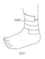
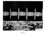
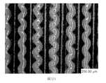
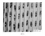
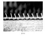
由於結合隨附圖式與以下本揭露之各個實施例的實施方式可更完整理解本揭露,其中:圖1為依據本揭露之聚合網狀織物之實施例的截面側視圖;圖2為依據本揭露之聚合網狀織物之實施例的透視圖;圖3為依據本揭露之聚合網狀織物之另一實施例之平面的示意性截面圖,其中該聚合網狀織物與例如吸收組件之基材相接;圖4為依據本揭露之聚合網狀織物之再另一實施例之平面的示意性截面圖;圖5為依據本揭露之聚合網狀織物之又另一實施例之平面的示意性截面圖;圖6為依據本揭露之聚合網狀織物之又另一實施例之平面的示意性截面圖;圖7為依據本揭露之聚合網狀織物之又另一實施例之平面的示意性截面圖;圖8為依據本揭露之聚合網狀織物之再另一實施例之平面的示意性截面圖;圖9為墊片之實施例的平面圖,其適用於可形成例如圖1至圖4所示之聚合網狀織物的墊片序列;圖10為墊片之另一實施例的平面圖,其適用於可形成例如圖1至圖7所示之聚合網狀織物的墊片序列;圖11為墊片之另一實施例的平面圖,其適用於可形成例如圖1至圖4所示之聚合網狀織物的墊片序列;圖12A為墊片序列之透視總成圖,其運用圖9、圖10及圖11之墊片,經組態以形成如圖1所示之聚合網狀織物之一部分;圖12B為圖12A中標示為「12B」之部分的放大視圖;圖13為墊片之實施例的平面圖,其適用於可形成例如圖5所示之聚合網狀織物的墊片序列;圖14為墊片之另一實施例的平面圖,其適用於可形成例如圖5所示之聚合網狀織物的墊片序列;圖15A為墊片序列之透視總成圖,其運用圖10、圖13及圖14之墊片,經組態以形成如圖5所示之聚合網狀織物之一部分;圖15B為圖15A中標示為「15B」之部分的放大視圖;圖16為墊片之實施例的平面圖,其適用於可形成例如圖6所示之聚合網狀織物的墊片序列;圖17為墊片之另一實施例的平面圖,其適用於可形成例如圖6所示之聚合網狀織物的墊片序列;圖18A為墊片序列之透視總成圖,其運用圖10、圖11、圖16及圖17之墊片,經組態以形成如圖6所示之聚合網狀織物的一部分;圖18B為圖18A中標示為「18B」之部分的放大視圖;圖19為墊片之實施例的平面圖,其適用於可形成例如圖7所示之聚合網狀織物的墊片序列;圖20為墊片之另一實施例的平面圖,其適用於可形成例如圖7所示之聚合網狀織物的墊片序列;圖21A為墊片序列之透視總成圖,其運用圖10、圖14、圖19及圖20之墊片,經組態以形成如圖7所示之聚合網狀織物的一部分;圖21B為圖21A中標示為「21B」之部分的放大視圖;圖22為安裝座實例之分解透視圖,其適用於由圖12A、圖15A、圖18A、圖21A或圖27A中所示之多個重複之墊片序列所組成的擠出模具;圖23為圖22之安裝座的已組裝狀態透視圖;圖24為墊片之實施例的平面圖,其可用於形成用以製造例如圖8所示之聚合網狀織物的墊片序列;圖25為墊片之另一實施例的平面圖,其可用於形成用以製造例如圖8所示之聚合網狀織物的墊片序列;圖26為墊片之又另一實施例的平面圖,其可用於形成用以製造例如圖8所示之聚合網狀織物的墊片序列;圖27A為墊片序列之透視圖,其運用圖24至圖26之墊片,經組態以形成例如圖8所示之聚合網狀織物的一部分;圖27B為圖27A中標示為「27B」之部分的放大視圖;圖28為依據本揭露之吸收物品之實例的示意分解圖;圖29為腳之透視圖,其顯示依據本揭露作為包覆物之聚合網狀織物的實施例;圖30為實例1之聚合網狀織物的俯視照片;圖31A和圖31B分別為實例2之聚合網狀織物的俯視和側視照片;圖32A和圖32B分別為實例3之聚合網狀織物的俯視和側視照片;圖33A和圖33B分別為實例4之聚合網狀織物的俯視和側視照片;圖34A和圖34B分別為實例6之聚合網狀織物的俯視和側視照片;以及圖35為測試架之照片,其用於評估實例1、實例1b、實例4a、實例4b、實例6a及實例6b之流體穿透時間。The present disclosure can be understood more completely by combining the accompanying drawings with the following embodiments of the present disclosure, in which: FIG. 1 is a cross-sectional side view of an embodiment of a polymer mesh fabric according to the present disclosure; FIG. 2 is a cross-sectional side view of an embodiment of a polymer mesh fabric according to the present disclosure; A perspective view of an embodiment of the disclosed polymer mesh fabric; FIG. 3 is a schematic cross-sectional view of another embodiment of the polymer mesh fabric according to the present disclosure, wherein the polymer mesh fabric and the base material of the absorbent component Figure 4 is a schematic cross-sectional view of the plane of another embodiment of the polymer mesh fabric according to the present disclosure; Figure 5 is a schematic view of the plane of another embodiment of the polymer mesh fabric according to the present disclosure Sectional view; Figure 6 is a schematic cross-sectional view of the plane of another embodiment of the polymer mesh fabric according to the present disclosure; Figure 7 is a schematic view of the plane of another embodiment of the polymer mesh fabric according to the present disclosure 8 is a schematic cross-sectional view of another embodiment of the polymer mesh fabric according to the present disclosure; FIG. 9 is a plan view of an embodiment of a gasket, which is suitable for forming, for example, FIGS. 1 to 4 The spacer sequence of the polymer mesh fabric shown; Figure 10 is a plan view of another embodiment of the spacer, which is suitable for forming the spacer sequence of the polymer mesh fabric shown in Figures 1 to 7, for example; Figure 11 It is a plan view of another embodiment of the gasket, which is suitable for forming a gasket sequence such as the polymer mesh fabric shown in FIGS. 1 to 4;Figure 12A is a perspective assembly view of the gasket sequence, which uses the gaskets of Figure 9, Figure 10 and Figure 11 to be configured to form part of the polymer mesh fabric shown in Figure 1; Figure 12B is in Figure 12A An enlarged view of the part marked "12B"; Figure 13 is a plan view of an embodiment of a gasket, which is suitable for forming a gasket sequence such as the polymer mesh fabric shown in Figure 5; Figure 14 is another gasket A plan view of an embodiment, which is suitable for forming a gasket sequence such as the polymer mesh fabric shown in Figure 5; Figure 15A is a perspective assembly view of the gasket sequence, which uses the gaskets of Figures 10, 13 and 14 , Configured to form a part of the polymer mesh fabric as shown in Figure 5; Figure 15B is an enlarged view of the part labeled "15B" in Figure 15A; Figure 16 is a plan view of an embodiment of the gasket, which is suitable for A spacer sequence such as the polymer mesh fabric shown in FIG. 6 can be formed; FIG. 17 is a plan view of another embodiment of the spacer, which is suitable for forming a spacer sequence such as the polymer mesh fabric shown in FIG. 6; Figure 18A is a perspective assembly view of the spacer sequence, which uses the spacers of Figure 10, Figure 11, Figure 16 and Figure 17 to be configured to form a part of the polymer mesh fabric as shown in Figure 6; Figure 18B is Figure 18A is an enlarged view of the part labeled "18B"; Figure 19 is a plan view of an embodiment of a gasket, which is suitable for forming a gasket sequence such as the polymer mesh fabric shown in Figure 7; Figure 20 is a gasket A plan view of another embodiment, which is suitable for forming a spacer sequence such as the polymer mesh fabric shown in FIG. 7;Figure 21A is a perspective assembly view of the gasket sequence, which uses the gaskets of Figure 10, Figure 14, Figure 19 and Figure 20 to be configured to form a part of the polymer mesh fabric as shown in Figure 7; Figure 21B is An enlarged view of the part labeled "21B" in Figure 21A; Figure 22 is an exploded perspective view of an example of a mounting seat, which is suitable for multiple repetitions shown in Figure 12A, Figure 15A, Figure 18A, Figure 21A or Figure 27A Figure 23 is a perspective view of the assembled state of the mounting seat of Figure 22; Figure 24 is a plan view of an embodiment of the gasket, which can be used to form the one shown in Figure 8 The spacer sequence of the polymer mesh fabric; Figure 25 is a plan view of another embodiment of the spacer, which can be used to form the spacer sequence for the polymer mesh fabric shown in Figure 8; Figure 26 is the spacer sequence A plan view of yet another embodiment, which can be used to form a shim sequence used to manufacture the polymer mesh fabric shown in FIG. 8; FIG. 27A is a perspective view of the shim sequence, which uses the shim of FIGS. 24 to 26 , Configured to form a part of the polymeric mesh fabric shown in Figure 8; Figure 27B is an enlarged view of the part labeled "27B" in Figure 27A; Figure 28 is a schematic exploded view of an example of an absorbent article according to the present disclosure Figure 29 is a perspective view of the foot, which shows an embodiment of a polymer mesh fabric as a covering according to the present disclosure; Figure 30 is a top view of the polymer mesh fabric of Example 1;Figures 31A and 31B are the top and side photos of the polymer mesh fabric of Example 2; Figures 32A and 32B are the top and side photos of the polymer mesh fabric of Example 3, respectively; Figures 33A and 33B are examples, respectively 4 the top and side photos of the polymer mesh fabric; Figure 34A and Figure 34B are the top and side photos of the polymer mesh fabric of Example 6, respectively; and Figure 35 is a photo of the test frame, which is used to evaluate Example 1. The fluid breakthrough time of Example 1b, Example 4a, Example 4b, Example 6a, and Example 6b.
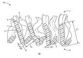
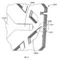
圖1繪示依據本揭露之聚合網狀織物10之實施例的側視圖。聚合網狀織物10包括聚合條帶1、及聚合股線3。聚合條帶1及聚合股線3各具有長度、寬度「w1」與「w3」、以及高度「h1」與「h3」。聚合條帶1及股線3的長度為最長尺寸且未顯示於圖1中。寬度為最短尺寸。條帶之高度「h1」以及股線的高度「h3」一般分別介於各者之長度及寬度之間。然而,股線3亦可具有高度「h3」,其實質上相同於其寬度「w3」。對於圓形股線,高度及寬度皆可指直徑。至少一些聚合條帶的高寬比為至少三比一。在一些實施例中,至少一些聚合條帶的高寬比為至少5:1、7:1、8:1、10:1、11:1、15:1、20:1、30:1、或40:1。聚合條帶的高度一般大於聚合股線的高度。在一些實施例中,聚合條帶之各者的高度係至少單一聚合股線的高度的2、2.5、3、5、10、或20倍大。聚合條帶的高度可位於從50微米至3毫米(mm)的範圍內。在一些實施例中,聚合條帶的高度係大於750微米。在這些實施例的一些中,聚合條帶的高度範圍係從大於750微米至3mm(例如,0.775mm至2mm、或0.8mm至1.5mm)。在一些實施例中,聚合條帶或聚合股線之至少一者的高度小於750微米。在這些實施例的一些中,聚合條帶或聚合股線之至少一者的高度範圍為0.1mm到小於750微米(例如,0.3mm至0.745mm、或0.5mm至0.745mm)。FIG. 1 shows a side view of an embodiment of a
圖2繪示依據本揭露之聚合網狀織物20之實施例的透視圖。在此透視圖中,可觀察到聚合條帶及股線之長度「l」。FIG. 2 shows a perspective view of an embodiment of a
再次參照圖1及圖2,聚合條帶1、11、21各自具有第一主表面2、12,其為間斷地相接於單個聚合股線3、13。亦即,兩個或更多個聚合股線未相接到聚合條帶的第一主表面。在聚合條帶的第一主表面間斷地相接於單個聚合股線的情形中,可觀察到該聚合股線在接合到聚合條帶與聚合股線相反側上的另一部分的網狀織物之間振盪。在圖2所圖示的實施例中,兩個毗鄰的聚合條帶11、21由單一聚合股線13相接在一起,單一聚合股線13至少部分交錯地接合至兩個毗鄰的聚合條帶11、21。然而,此並非必要條件。舉例而言,在一些實施例中,聚合股線可在接合至聚合條帶及非振盪股線之間振盪,其中該非振盪股線的高寬比並不一定為至少三比一。由於聚合條帶的主表面間斷地接合至聚合股線,該聚合股線至少部分地交錯地接合至該聚合條帶及網狀織物的另一股線或條帶,因此該等聚合條帶一般不與該等聚合股線相交。在本文揭示任何的聚合網狀織物實施例中,聚合物的股線及條帶係透過形成經疊加交點或者經插入中間交點,而一般彼此實質上不相交(例如,在數量上至少百分之50(至少55、60、65、70、75、80、85、90、95、99、或甚至100)彼此不相交)。1 and 2 again, the
在圖1中,聚合條帶1的所有高度h1約為相同大小,聚合股線3的所有高度h3約為相同大小,但如圖2至圖4所示,此非係必要條件。例如,如圖3所示,可有兩個不同類型的聚合條帶31、41。聚合條帶31的高寬比大於聚合條帶41的高寬比。在圖2及圖4中,聚合條帶11、21、51具有高度範圍。在圖4中,聚合條帶51在聚合網狀織物50之邊緣55上的高寬比大於在中心57的高寬比。在這些實施例中,至少一些聚合條帶51具有至少三比一的高寬比。In Fig. 1, all heights h1 of the
而在圖1至圖4中,聚合網狀織物中各種聚合條帶及聚合股線之間的間距約略相等(此為非必要條件)。任二毗鄰的聚合條帶1、11、21、31、41、51或任二毗鄰的聚合股線3、13、33、53之間的間距可在跨網方向有所變化。例如,任兩個毗鄰的聚合條帶或任兩個毗鄰的聚合股線在網狀織物中心可比在邊緣更加靠近彼此,或反之亦然。In Figures 1 to 4, the spacing between the various polymeric strips and polymeric strands in the polymeric mesh fabric is approximately equal (this is not a necessary condition). The spacing between any two
在圖1至圖4所繪示的實施例中,聚合條帶及聚合股線交錯。在依據本揭露及/或依據本文所揭示之方法製成之聚合網狀織物之一些實施例中,聚合條帶及聚合股線在至少一部分的網狀織物中交錯。在這些實施例以及甚至在聚合條帶及聚合股線未交錯的其他實施例中,一般地,聚合條帶的各主表面係間斷地接合至僅一個聚合股線。再者,應注意的是圖3、圖4、圖5、圖6及圖8(在下文敘述)所示之聚合網狀織物平面之截面圖所示的間距為理想情形。在典型截面平面圖中,並非所有聚合股線均會呈現以相同方式接合至聚合條帶的主表面。取而代之地,股線的位置可能更像圖7的截面平面視圖及圖1所示的側視圖中所示。In the embodiments shown in FIGS. 1 to 4, the polymer strips and polymer strands are staggered. In some embodiments of the polymeric mesh fabric made according to the present disclosure and/or according to the methods disclosed herein, the polymeric strips and polymeric strands are interlaced in at least a portion of the mesh fabric. In these embodiments and even in other implementations where the polymer strips and polymer strands are not interlacedIn the example, generally, each major surface of the polymeric strip is intermittently joined to only one polymeric strand. Furthermore, it should be noted that the spacing shown in the cross-sectional views of the plane of the polymeric mesh fabric shown in FIGS. 3, 4, 5, 6 and 8 (described below) is an ideal situation. In a typical cross-sectional plan view, not all polymeric strands will appear to be joined to the major surface of the polymeric strip in the same way. Instead, the position of the strands may be more like that shown in the cross-sectional plan view of FIG. 7 and the side view of FIG. 1.
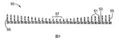
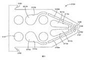
依據本揭露之聚合網狀織物之組態的一些實施例繪示於圖1、圖5及圖6中。在圖1中,聚合條帶1各自具有中央線4,其對分主表面2;以及第一及第二邊緣6、8,該等第一及第二邊緣係對稱地設置在中央線4之相反側上。對聚合條帶1之各者而言,相關聯的單一聚合股線3係在中央線4及第一邊緣6之間的位置接合至主表面2。在所繪示的實施例中,單一聚合股線3係在中央線4及第一邊緣6之間的位置接合至兩個毗鄰的聚合條帶1。換言之,單一聚合股線3係在與第二邊緣8相比更接近第一邊緣6之處接合至主表面2。再用另一種方式解釋,聚合網狀織物10具有橫向於聚合條帶1之主表面2的第一及第二反向的主表面5、7。聚合網狀織物10的第二主表面7包含聚合條帶1的第二邊緣8,且聚合網狀織物10的第一主表面5包含聚合條帶1的第一邊緣6以及至少一些聚合股線3的部分。Some embodiments of the configuration of the polymer mesh fabric according to the present disclosure are shown in FIG. 1, FIG. 5, and FIG. 6. In Figure 1, the
在圖5所示之實施例中,聚合條帶61及聚合股線63係垂直對準。在這些實施例中,單一聚合股線63係在包括中央線64的位置接合至主表面62。再用另一種方式解釋,聚合網狀織物60具有橫向於聚合條帶61之主表面62的第一及第二反向的主表面65、67。聚合網狀織物60的第一主表面65包含聚合條帶61的第一邊緣66,且聚合網狀織物60的第二主表面67包含聚合條帶61的第二邊緣68。第一及第二主表面65、67皆未包含聚合股線63的一部分。In the embodiment shown in FIG. 5, the polymeric strip 61 and the polymeric strand 63 are vertically aligned. In these embodiments, a single polymeric strand 63 is joined to the major surface 62 at a location that includes the central line 64. To explain in another way, the polymeric mesh fabric 60 has first and second opposite main surfaces 65 and 67 transverse to the main surface 62 of the polymeric strip 61.The first major surface 65 of the polymeric mesh fabric 60 includes the
在圖6所示之實施例中,聚合條帶71、81各具有中央線74、84,該等中央線對分主表面72、82,且第二邊緣(頂部)78、88與第一邊緣(底部)76、86係對稱地設置在中央線74、84的相對側上,其中一些聚合條帶81係在中央線84及第二邊緣(頂部)88間的位置接合至其等之單一聚合股線73,且一些聚合條帶71係在中央線74在第一邊緣(底部)76間的位置接合至其等之單一聚合股線73。換言之,單一聚合股線73係接合至聚合條帶71之第一部分的主表面72,且與第二邊緣78相比更接近第一邊緣76,且單一聚合股線73係接合至聚合條帶81之第二部分的主表面82,其較接近第二邊緣88而非第一邊緣86。用另一種方式解釋,聚合網狀織物70具有橫向於聚合條帶71、81之主表面72、82的第一及第二反向的主表面75、77。聚合網狀織物70的第一主表面75包含第一組的聚合條帶81之第一邊緣86,且聚合網狀織物70的第二主表面77包含第二組的聚合條帶71之第二邊緣78。第一及第二主表面75、77皆未包含聚合股線73的一部分。第一組的聚合條帶81未延伸至第二主表面77,且第二組的聚合條帶71未延伸至第一主表面75。關於此實施例之進一步的細節可在2014年2月28日提出申請之共同申請審理中之美國專利申請案序號第61/946,592號(Legatt等人)中找到,且其全文係併入本文中以供參照。In the embodiment shown in FIG. 6, the polymeric strips 71, 81 each have
雖然在圖1至圖6中,聚合條帶的寬度w1各自為大約相同,且聚合股線的寬度w3皆大約相同,但此亦非必要條件。該等聚合條帶及/或聚合股線的寬度可跨網狀織物變化(例如,在橫向於聚合條帶與聚合股線之長度的方向上)。例如,聚合條帶或聚合股線之至少一者在網狀織物的中心可具有比在邊緣處更大的寬度w1或w3,或者反之亦然。Although in FIGS. 1 to 6, the widths w1 of the polymeric strips are approximately the same, and the widths w3 of the polymeric strands are approximately the same, but this is not a necessary condition. The width of the polymeric strips and/or polymeric strands can vary across the mesh fabric (for example, in a direction transverse to the length of the polymeric strips and polymeric strands). For example, at least one of the polymeric strips or polymeric strands may have a greater width w1 or w3 at the center of the mesh fabric than at the edges, or vice versa.
在圖1至圖6所繪示的實施例中,聚合條帶的寬度w1從第二邊緣8、78、88至第一邊緣6、76、86皆是均一的。再次說明,此非必要條件。舉例而言,聚合網狀織物80具有在頂部及底部邊緣之間之寬度非均一的條帶,如圖7所顯示。此實施例類似於圖5所示之實施例,其中聚合條帶61a及聚合股線63a係垂直置中。然而,在聚合網狀織物80中,聚合條帶61a在包括中央線64a之位置的寬度比其在頂部及底部邊緣68及66處的寬度更寬。也就是說,在所繪示的實施例中,聚合條帶61a在其接合至聚合股線63a之位置的寬度較寬。In the embodiment shown in FIGS. 1 to 6, the width w1 of the polymer strip is uniform from the
在圖7所繪示的聚合網狀織物80中,聚合條帶61a係設計成在接近中央線64a之處比在頂部及底部邊緣68及66處具有更寬的寬度。聚合條帶的寬度亦可設計為以其他方式從頂部邊緣至底部邊緣改變。舉例而言,在頂部邊緣68及/或底部邊緣66的寬度可大於在中央線64a附近的寬度。聚合股線可在這些位置接合至聚合條帶。聚合條帶的寬度也可因擠出過程而產生隨機變化。在任何聚合條帶寬度為非均一的情況下,用於決定高寬比的聚合條帶寬度w1係以其最小寬度為準。In the
同樣地,聚合條帶的高度可以其最高高度為準。聚合條帶的高度係大致上均一。在本文所揭示之聚合網狀織物的任何實施例中的聚合條帶,一般不會具有任何從聚合條帶邊緣立起的不連續柱體(如機械緊固件或鉤)。同樣地,在本文所揭示之聚合網狀織物的任何實施例中的聚合網狀織物,其第一或第二主表面上一般不會具有不連續柱體(如機械緊固件或鉤)。Likewise, the height of the polymeric strip may be based on its highest height. The height of the polymeric strips is approximately uniform. The polymeric strips in any of the embodiments of polymeric mesh fabrics disclosed herein generally do not have any discontinuous columns (such as mechanical fasteners or hooks) rising from the edges of the polymeric strips. Likewise, the polymeric mesh fabric in any embodiment of the polymeric mesh fabric disclosed herein generally does not have discontinuous columns (such as mechanical fasteners or hooks) on its first or second major surface.
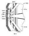
在聚合條帶各自具有對分主表面的中央線以及對稱地設置於中央線相對側之第一及第二邊緣的一些實施例中,聚合條帶的第一邊緣包含與聚合條帶之第二邊緣不同的組成物。這種聚合網狀織物的實施例顯示於圖8。在圖8中,聚合網狀織物90包括聚合條帶91及聚合股線93。聚合條帶91各自具有第一部分91a及第二部分91b。第一及第二部分91a及91b是由不同聚合物組成物所製成。同樣的,聚合股線93各自具有第一部分93a及第二部分93b。在這些實施例中,聚合網狀織物90具有橫向於聚合條帶91之主表面92的第一及第二反向的主表面95、97。聚合網狀織物90的第一主表面95包含聚合條帶91的第一邊緣96以及聚合股線93的第二部分93b,且聚合網狀織物90的第二主表面97包含聚合條帶91的第二邊緣98。聚合條帶91的第一部分91a(且因此第二邊緣98)包含第一聚合物組成物,且聚合條帶91的第二部分91b(且因此第一邊緣96)包含第二聚合物組成物。聚合股線的第一部分93a包含第三聚合物組成物,且聚合股線93的第二部分93b包含第四聚合物組成物。在此繪示的實施例中,至少第一及第二聚合物的組成物是不同的,並且第一聚合物組成物未延伸至聚合條帶91的第一邊緣96。In some embodiments in which the polymeric strips each have a central line that bisects the main surface and the first and second edges symmetrically disposed on opposite sides of the central line, the first edge of the polymeric strip includes and the second edge of the polymeric strip Different composition of edges. An example of such a polymeric mesh fabric is shown in FIG. 8. In FIG. 8, the
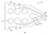
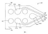
雖然也可使用其他方法,但在本文所揭示的任何聚合網狀織物實施例中的聚合網狀織物,可由依據本揭露之擠出模具及/或方法便利地製備。依據本揭露的擠出模具,其具有從模具內部的腔到施配孔口的多種通道。施配孔口各自具有寬度及高度,其寬度為對應於特定聚合條帶或聚合股線寬度之尺寸,其高度為對應於所得之擠出聚合網狀織物的厚度以及特定聚合條帶或聚合股線高度之尺寸。Although other methods can also be used, the polymeric mesh fabric in any embodiment of the polymeric mesh fabric disclosed herein can be conveniently prepared by the extrusion die and/or method according to the present disclosure. According to the extrusion die of the present disclosure, it has multiple channels from the cavity inside the die to the dispensing orifice. The dispensing orifices each have a width and a height, the width of which is the size corresponding to the width of the specific polymer strip or polymer strand, and the height of which corresponds to the thickness of the resulting extruded polymer mesh fabric and the specific polymer strip or polymer strand The size of the line height.
在依據本揭露之製造聚合網狀織物施配擠出模具及方法中,擠出模具有至少一腔、表面、及位於至少一腔及施配表面之間的流體通道。該施配表面具有由第二施配孔口之陣列所隔開的第一施配孔口之陣列。這代表任兩個第一施配孔口之間具有至少一第二施配孔口。然而,任兩個第一施配孔口之間亦可能具有一個以上的第二施配孔口,且在其之間可具有處於並排組態之除了第二施配孔口以外的其他施配孔口。In the dispensing extrusion die and method for manufacturing a polymeric mesh fabric according to the present disclosure, the extrusion die has at least one cavity, a surface, and a fluid channel between the at least one cavity and the dispensing surface. The dispensing surface has an array of first dispensing orifices separated by an array of second dispensing orifices. This means that there is at least one second dispensing orifice between any two first dispensing orifices. However, there may be more than one second dispensing orifice between any two first dispensing orifices, and there may be other dispensing orifices in a side-by-side configuration besides the second dispensing orifice between them. Orifice.
流體通道能使聚合物間物理分隔,該分隔從該至少一腔(例如,第一及第二腔,及可選之擠出模具內的任何其他模具腔)到流體通道進入施配孔口為止。模具內部的不同通道的形狀可為相同或不同。通道截面形狀的實例包括圓形、方形、及矩形等形狀。這些截面形狀、聚合物材料選擇及出模膨脹會影響條帶及股線的截面形狀。The fluid channel enables the physical separation of polymers from the at least one cavity (for example, the first and second cavities, and optionally any other mold cavities in the extrusion die) to the fluid channel entering the dispensing orifice . The shapes of different channels inside the mold can be the same or different. Examples of the cross-sectional shape of the channel include circular, square, and rectangular shapes. These cross-sectional shapes, polymer material selection and mold expansion will affect the cross-sectional shape of the strips and strands.
在包括圖9至圖27A及圖27B所示之實施例的許多實施例中,擠出模具包括至少第一腔及第二腔,並具有介於第一腔及第一施配孔口之間的第一流體通道、以及介於第二腔及第二施配孔口之間的第二流體通道。第一及第二施配孔口各自具有高度及寬度,第一施配孔口各自具有至少3:1的高寬比(在一些實施例中,具有至少5:1、8:1、10:1、11:1、15:1、20:1、30:1、或40:1的高寬比),且第一施配孔口高度大於(在一些實施例中,至少2、2.5、3、5、10、或20倍大)第二施配孔口的高度。在一些實施例中,特別是擠出模具的實施例,第一施配孔口、第二施配孔口、及任何其他施配孔口係橫跨施配表面逐一配置。亦即,在這些實施例中,在模具的寬度維度中,施配孔口係個別配置或逐一配置(不論施配孔口在這些實施例中如何排列)。例如,施配孔口未在高度方向上以兩個、三個、或多個一組堆疊。In many embodiments including the embodiments shown in FIGS. 9-27A and 27B, the extrusion die includes at least a first cavity and a second cavity, and has a gap between the first cavity and the first dispensing orifice The first fluid channel and the second fluid channel between the second cavity and the second dispensing orifice. The first and second dispensing orifices each have a height and a width, and the first dispensing orifices each have an aspect ratio of at least 3:1 (in some embodiments, at least 5:1, 8:1, 10: 1, 11:1, 15:1, 20:1, 30:1, or 40:1 aspect ratio), and the height of the first dispensing orifice is greater than (in some embodiments, at least 2, 2.5, 3 , 5, 10, or 20 times larger) the height of the second dispensing orifice. In some embodiments, particularly the embodiment of the extrusion die, the first dispensing orifice, the second dispensing orifice, and any other dispensing orifices are arranged one by one across the dispensing surface. That is, in these embodiments, in the width dimension of the mold, the dispensing orifices are arranged individually or one by one (regardless of how the dispensing orifices are arranged in these embodiments). For example, the dispensing orifices are not stacked in groups of two, three, or more in the height direction.
在依據本揭露之方法的一些實施例中,以第一速度自第一施配孔口施配聚合條帶,同時以第二速度自第二施配孔口施配聚合股線,且第二速度為第一速度的至少兩倍。在一些實施例中,第二速度範圍為第一速度的2至6倍或2至4倍。在擠出模具包括至少第一及第二腔的一些實施例中,以第一壓力供應第一聚合物組成物給擠出模具的第一腔,以便以第一速度自第一施配孔口之陣列施配聚合條帶;以第二壓力供應第二聚合物組成物給擠出模具的第二腔,以便以第二速度自第二施配孔口之陣列施配聚合股線,其中第二速度為第一速度的至少2倍(在一些實施例中,2至6倍或2至4倍)。In some embodiments of the method according to the present disclosure, the polymeric strip is applied from the first dispensing orifice at a first speed, while the polymeric strands are applied from the second dispensing orifice at a second speed, and the second speed The speed is at least twice the first speed. In some embodiments, the second speed range is 2 to 6 times or 2 to 4 times the first speed. In some embodiments where the extrusion die includes at least first and second cavities, the first polymer composition is supplied to the first cavity of the extrusion die at a first pressure so as to dispense from the first orifice at a first speed. Dispense polymeric strips in the array; supply the second polymer composition to the second cavity of the extrusion die at a second pressure, so as to dispense polymeric strands from the array of second dispensing orifices at a second speed, wherein the first The second speed is at least 2 times the first speed (in some embodiments, 2 to 6 times or 2 to 4 times).
在依據本揭露之方法的其他實施例中,以第一速度自第一施配孔口施配聚合條帶的同時以第二速度自第二施配孔口施配聚合股線,且第一速度為第二速度的至少兩倍。在一些實施例中,第一速度的範圍為第二速度的2至6倍或2至4倍。在擠出模具包括至少第一及第二腔的一些實施例中,以第一壓力供應第一聚合物組成物給擠出模具的第一腔,以便以第一速度自第一施配孔口之陣列施配聚合條帶;以第二壓力供應第二聚合物組成物給擠出模具的第二腔,以便以第二速度自第二施配孔口之陣列施配聚合股線,其中第一速度為第二速度的至少2倍(在一些實施例中,2至6倍或2至4倍)。In other embodiments of the method according to the present disclosure, the polymeric strip is applied from the first dispensing orifice at the first speed while the polymeric strands are being applied from the second dispensing orifice at the second speed, and the first The speed is at least twice the second speed. In some embodiments, the range of the first speed is 2 to 6 times or 2 to 4 times the second speed. In some embodiments where the extrusion die includes at least first and second cavities, the first polymer composition is supplied to the first cavity of the extrusion die at a first pressure so as to dispense from the first orifice at a first speed. Dispense polymeric strips in the array; supply the second polymer composition to the second cavity of the extrusion die at a second pressure, so as to dispense polymeric strands from the array of second dispensing orifices at a second speed, wherein the first One speed is at least 2 times the second speed (in some embodiments, 2 to 6 times or 2 to 4 times).
雖然可使聚合條帶或聚合股線的其中一者振盪,但一般可在聚合股線振盪時觀察到較大的接合區域。因此,在如下述的方法中,聚合股線被敘述為振盪股線。Although either the polymeric strip or the polymeric strand can be oscillated, generally a larger bonding area can be observed when the polymeric strand oscillates. Therefore, in the method described below, the polymeric strands are described as oscillating strands.
聚合條帶及聚合股線可以調節其大小,舉例而言,藉由擠出聚合物的組成物、擠出股線的速度、及/或孔口設計(例如,截面面積(如孔口的高度及/或寬度))。如同國際專利申請公開第WO 2013/028654號(Ausen等人)所教示,一種第一聚合物孔口面積比第二聚合物孔口面積大三倍的施配表面,其可能無法產生聚合條帶之高度大於聚合股線之高度的網狀織物(取決於聚合物組成物的特性及腔內壓力)。在依據本揭露的擠出模具及方法的一些實施例中,孔口的高寬比係至少5:1。The size of the polymeric strips and polymeric strands can be adjusted, for example, by extruding the composition of the polymer, the speed of the extrusion strand, and/or the orifice design (for example, the cross-sectional area (such as the height of the orifice) And/or width)). As taught in International Patent Application Publication No. WO 2013/028654 (Ausen et al.), a dispensing surface with a first polymer orifice area three times larger than a second polymer orifice area may not produce polymerized bands A mesh fabric whose height is greater than the height of the polymer strands (depending on the characteristics of the polymer composition and the pressure in the cavity). In some embodiments of the extrusion die and method according to the present disclosure, the aspect ratio of the orifice is at least 5:1.
為求便利起見,根據及/或可用於實施本揭露的擠出模具可包含複數個墊片。複數個墊片共同界定至少一腔、施配表面及介於至少一腔及施配表面之間的流體通道。在一些實施例中,複數個墊片包含複數個墊片序列,其中各序列包含至少一提供第一流體通道(其介於至少一腔及第一施配孔口之至少一者之間)的第一墊片,以及至少一提供第二流體通道(其介於至少一腔及第二施配孔口之至少一者之間)的第二墊片。在一些實施例中,墊片共同界定第一腔及第二腔,具有與第一腔流體連通的複數個第一施配孔口、以及與第二腔流體連通的複數個第二施配孔口之擠出模具。For convenience, the extrusion die according to and/or applicable to the implementation of the present disclosure may include a plurality of gaskets. A plurality of shims together define at least one cavity, dispensing surface and mediumA fluid channel between at least one cavity and the dispensing surface. In some embodiments, the plurality of spacers includes a plurality of spacer sequences, wherein each sequence includes at least one providing a first fluid channel (which is between at least one of the at least one cavity and the first dispensing orifice) A first gasket, and at least one second gasket providing a second fluid passage (between at least one of the at least one cavity and the second dispensing orifice). In some embodiments, the gasket jointly defines the first cavity and the second cavity, and has a plurality of first dispensing holes in fluid communication with the first cavity and a plurality of second dispensing holes in fluid communication with the second cavity Mouth extrusion die.
在一些實施例中,根據提供不同類型的墊片序列的計畫組裝墊片。由於不同的應用可有不同的要求,序列可具有多樣數量的墊片。序列可為重複序列,其不限於在特定區域的特定數量的重複。或者,序列可以是不規律重複,而可使用不同的墊片序列。In some embodiments, the gaskets are assembled according to a plan to provide different types of gasket sequences. Since different applications may have different requirements, the sequence can have a diverse number of shims. The sequence may be a repetitive sequence, which is not limited to a specific number of repetitions in a specific region. Alternatively, the sequence may be repeated irregularly, and a different shim sequence may be used.
可用以提供聚合網狀織物之依據本揭露的複數個墊片係展示於圖9至圖11、圖12A及圖12B中。現請參照圖9,所繪示者為墊片100的平面圖。墊片100可用於圖12A及圖12B所示的墊片序列1000。可用於此序列中的其他墊片如圖10及圖11所示。墊片100具有第一孔隙110a、第二孔隙110b、及第三孔隙110c。當組裝墊片序列1000時,墊片100、200、及300中的第一孔隙110a、210a、及310a共同界定第一腔1012a的至少一部分。同樣地,墊片100、200、及300中的第二孔隙110b、210b、及310b共同界定第二腔1012b的至少一部分,且墊片100、200、及300中的第三孔隙110c、210c、及310c共同界定第三腔1012c的至少一部分。墊片100具有數個孔147,以允許例如螺栓通過,以固持墊片100及下列敘述之其他者形成總成。墊片100具有施配表面167,並在此特定實施例中,施配表面167具有標記槽180(可用以在將墊片組裝入模具時,便利地將墊片與適當形狀鍵對齊)及識別缺口182(以幫助驗證模具已經以所需的方式組裝完成)。墊片100具有肩部190及192,其可便利地藉由與圖22及圖23相關之下述壓縮塊2204加以接合。墊片100具有施配開口156,但在施配開口156與任一孔隙110a、110b、或110c之間未完整連接。舉例而言,經由例如通道168a從第一孔隙110a到施配開口156並無連接,但當墊片100如同總成圖1000(參見圖12A)所繪示般與墊片200及300組裝在一起時,流體具有到達施配表面的路徑1068a。可將導管154的尺寸(特別是施配開口156位於其末端者)設計成為由其所擠出之聚合股線提供所欲之尺寸。施配開口156的尺寸及通道158a的尺寸也會影響所期望的股線速度。A plurality of spacers according to the present disclosure that can be used to provide a polymeric mesh fabric are shown in FIGS. 9 to 11, 12A, and 12B. Referring now to FIG. 9, what is shown is a plan view of the
現請參照圖10,所繪示者為墊片200的平面圖。墊片200具有第一孔隙210a、第二孔隙210b及第三孔隙210c。當墊片200如圖12A所示與其他者組裝在一起時,孔隙210a幫助界定第一腔1012a,孔隙210b幫助界定第二腔1012b,而孔隙210c幫助界定第三腔1012c。墊片200具有數個孔247,以允許例如螺栓通過,以固持墊片200及下列敘述之其他者形成總成。墊片200具有施配表面267,並在此特定實施例中,施配表面267具有標記槽280及識別缺口282。墊片200亦具有肩部290及292。因為此墊片沿著模寬度產生非施配區域,因此從腔到施配表面267沒有任何通道。在使用上,墊片200分隔產生聚合股線3的墊片100與產生聚合條帶1的墊片300。Please refer to FIG. 10, which is a plan view of the
現請參照圖11,所繪示者為墊片300的平面圖。墊片300具有第一孔隙310a、第二孔隙310b及第三孔隙310c。當墊片300如圖12A所示與其他者組裝在一起時,孔隙310a幫助界定第一腔1012a,孔隙310b幫助界定第二腔1012b,且孔隙310c幫助界定第三腔1012c。墊片300具有數個孔347,以允許例如螺栓通過,以固持墊片300及下列敘述之其他者形成總成。墊片300具有施配表面367,並在此特定實施例中,施配表面367具有標記槽380。墊片300亦具有肩部390及392。墊片300具有施配開口356,但在施配開口356及任一孔隙310a、310b、或310c之間並無完整連接。舉例而言,經由例如通道368c從孔隙310至施配開口356並無連接,但如同序列1000所示(參見圖12A),當墊片300與墊片100及200組裝在一起時,流體之流動具有到達施配表面的路徑1068c。對比圖11及圖9,吾人可注意到施配開口356大於施配開口156。在一些實施例中,施配開口356的大小為施配開口156的至少兩倍。在一些實施例中,施配開口356為施配開口156的至少2.5、3、5、10、或20倍大。Please refer to FIG. 11, which is a plan view of the
圖12A及圖12B繪示墊片序列(統稱1000)的透視總成圖,其採用圖9至圖11的墊片,以生產如圖1所示的聚合網狀織物10。從左至右,序列1000包括兩個墊片100(可擠出聚合股線3)、兩個墊片200、兩個墊片300(可擠出聚合條帶1),以及兩個墊片200。第一施配孔口1001各自具有由高度h1001及寬度w1001所界定的高寬比。高寬比為至少三比一(在一些實施例中,至少5:1、8:1、10:1、11:1、15:1、20:1、30:1、或40:1)。第一施配孔口1001及第二施配孔口1003係藉由兩個墊片200來分隔。該分隔導致聚合網狀織物10中之聚合條帶1與聚合股線3的分隔。第一施配孔口高度h1001大於第二施配孔口高度h1003。在一些實施例中,第一施配孔口高度h1001係至少第二施配孔口高度h1003的2、2.5、3、5、10、或20倍大。FIGS. 12A and 12B are perspective assembly diagrams of the gasket sequence (collectively referred to as 1000), which use the gaskets of FIGS. 9 to 11 to produce the
對圖12A及12B所示之序列1000的修改可與序列1000組合使用,例如,為了製造如圖2、圖3及圖4所示之聚合網狀織物20、40及50。為製造圖3所示的聚合網狀織物40,序列1000可以與另一類似1000的序列交錯,舉例而言其中墊片300具有稍微更小的開口356者。雖然墊片300可用於擠出聚合條帶31,具有稍微更小的開口356之墊片可用於擠出聚合條帶41。在一些實施例中,序列1000可與另一類似1000的序列交錯,其中墊片300係以墊片100取代,且可調整來自腔1012c的聚合物流速,使得此股線不振盪。此序列可製造聚合網狀織物,其中聚合股線33於接合至聚合條帶31與接合至非振盪股線之間振盪,其中該非振盪股線的高寬比並不一定為至少三比一。為製造圖2所示之聚合網狀織物20,序列1000可與類似的序列組合,其中墊片300被修改成例如具有逐漸變小的開口356,以提供複數個墊片序列。雖然墊片300可用於擠出聚合條帶11,具有稍微更小的開口356之墊片可用於擠出聚合條帶21。此類的複數個墊片序列可以相反的順序重複,以提供如圖4所示之聚合網狀織物50。Modifications to the
例如,在使用圖12A及圖12B所示之擠出模具製造如圖1所示之聚合網狀織物的方法中,來自第一腔1012a的聚合物自第二施配孔口1003出射為聚合股線3,且來自第三腔1012c的聚合物自第一施配孔口1001出射為聚合條帶1。流體通道的尺寸及腔1012a及1012c中的壓力一般為選定,如此使得振盪聚合股線3的速度介於聚合條帶1之速度的約2及6倍(在一些實施例中,2及4倍)之間。為製造圖1所示之聚合網狀織物,第二腔1012b係為閒置,但此腔可用以導入聚合網狀織物10中的另一聚合物組成物。For example, in the method of using the extrusion die shown in FIGS. 12A and 12B to manufacture the polymer mesh fabric as shown in FIG. 1, the polymer from the
聚合網狀織物(例如圖5中的聚合網狀織物60所示者)可例如使用圖15A及圖15B所示的墊片序列來製造。圖15A及圖15B顯示墊片序列的透視總成,該墊片序列包括如上文所述與圖10相關之墊片200、以及下文所述分別與圖13及圖14相關的之墊片400和500。A polymeric mesh fabric (such as that shown in the polymeric mesh fabric 60 in FIG. 5) can be manufactured, for example, using the spacer sequence shown in FIGS. 15A and 15B. 15A and 15B show a perspective assembly of the gasket sequence, the gasket sequence includes the
現請參照圖13,所繪示者為墊片400的平面圖。墊片400具有第一孔隙410a、第二孔隙410b及第三孔隙410c。當墊片400如圖15所示與其他者組裝在一起時,孔隙410a幫助界定第一腔1112a,孔隙410b幫助界定第二腔1112b,且孔隙410c幫助界定第三腔1112c。墊片400具有數個孔447,以允許例如螺栓通過,以固持墊片400及下列敘述之其他者形成總成。墊片400具有施配表面467,並在此特定實施例中,施配表面467具有標記槽480及識別缺口482。墊片400亦具有肩部490及492。墊片400具有施配開口456,但在施配開口456及任一孔隙410a、410b、或410c之間並無完整連接。舉例而言,經由例如通道468a從孔隙410c到施配開口456並無連接,但當墊片400如同序列1100(參見圖15A)所繪示般與墊片200及500組裝在一起時,流體之流動在與圖式之平面相垂直的維度中具有到達施配表面的路徑1168a。456的尺寸可設計成為由其所擠出之聚合股線提供所欲之尺寸。施配開口456的尺寸及通往其之通道的尺寸亦會影響股線速度。Please refer to FIG. 13, which is a plan view of the
現請參照圖14,所繪示者為墊片500的平面圖。墊片500具有第一孔隙510a、第二孔隙510b、以及第三孔隙510c。當墊片500如圖15A及圖15B所示與其他者組裝在一起時,孔隙510a幫助界定第一腔1112a,孔隙510b幫助界定第二腔1112b,且孔隙510c幫助界定第三腔1112c。墊片500具有數個孔547,以允許例如螺栓通過,以固持墊片500及下列敘述之其他者形成總成。墊片500具有施配表面567,並在此特定實施例中,施配表面567具有標記槽580。墊片500亦具有肩部590及592。墊片500具有施配開口556,但在施配開口556及任一孔隙510a、510b、或510c之間並無完整連接。舉例而言,經由例如通道568b從孔隙510b到施配開口556並無連接,但當墊片500如同總成圖(參見圖15A)所繪示般與墊片200及400組裝在一起時,流體之流動具有到達施配表面的路徑1168b。Please refer to FIG. 14, which is a plan view of the
圖15A及圖15B繪示墊片序列(統稱1100)的透視總成圖,其採用圖10、圖13及圖14的墊片,以生產如圖5所示的聚合網狀織物60。從左至右,序列1100包括四個墊片400,該等墊片400可擠出聚合股線63;四個墊片200;兩個墊片500,該等墊片500可擠出聚合條帶61;及四個墊片200。施配孔口1101及1103係由四個墊片200來分隔。該分隔導致聚合網狀織物60中之聚合條帶61與聚合股線63的分隔。墊片序列1100類似於1000,惟施配孔口1101及1103係垂直對準,使第二施配孔口位於施配表面1167之截面中央。如圖12B所示之實施例,第一施配孔口1101各自具有由高度h1101及寬度w1101所界定的高寬比,該高寬比至少為三比一(在一些實施例中,至少5:1、8:1、10:1、11:1、15:1、20:1、30:1、或40:1),且第一施配孔口的高度h1101係為第二施配孔口的高度h1103的至少2、2.5、3、5、10、或20倍大。15A and 15B are perspective assembly views of the gasket sequence (collectively referred to as 1100), which use the gaskets of FIG. 10, FIG. 13 and FIG. 14 to produce the polymer mesh fabric 60 as shown in FIG. From left to right, the
例如,在使用圖15A及圖15B所示之擠出模具製造如圖5所示之聚合網狀織物的方法中,來自第一腔1112a的聚合物自第二施配孔口1103出射為聚合股線63,且來自第二腔1112b的聚合物自第一施配孔口1101出射為聚合條帶61。流體通道的尺寸及腔1112a及1112b中的壓力一般為選定,如此使得振盪聚合股線63的速度介於聚合條帶61之速度的約2及6倍(在一些實施例中,2及4倍)之間。為製造圖5所示之聚合網狀織物,第三腔1112c係為閒置,但此腔可用以導入聚合網狀織物60中的另一聚合物組成物。For example, in the method of using the extrusion die shown in FIGS. 15A and 15B to produce the polymer mesh fabric as shown in FIG. 5, the polymer from the
聚合網狀織物(例如圖6中的聚合網狀織物70所示者)可例如使用圖18A及圖18B所示的墊片序列來製造。圖18A及圖18B顯示墊片序列的透視總成,該墊片序列包括如上文所述分別與圖10及圖11相關之墊片200及300、以及下文所述之墊片600和700。A polymeric mesh fabric (such as that shown in the
現請參照圖16,所繪示者為墊片600的平面圖。墊片600具有第一孔隙610a、第二孔隙610b、以及第三孔隙610c。當墊片600如圖18A所示與其他者組裝在一起時,孔隙610a幫助界定第一腔1212a,孔隙610b幫助界定第二腔1212b,且孔隙610c幫助界定第三腔1212c。墊片600具有數個孔647,以允許例如螺栓通過,以固持墊片600及下列所述之其他者形成總成。墊片600具有施配表面667,並在此特定實施例中,施配表面667具有標記槽680及識別缺口682。墊片600亦具有肩部690及692。墊片600具有施配開口656,但在施配開口656及任一孔隙610a、610b、或610c之間並無完整連接。舉例而言,經由例如通道668b從孔隙610b至施配開口656並無連接,但當墊片600如同序列1200所示(參見圖18A)與墊片200、300、及700組裝在一起時,流體之流動具有到達施配表面的路徑1268b。656的尺寸可設計成為由其所擠出之聚合股線提供所欲之尺寸。施配開口656的尺寸及通往其之通道的尺寸也會影響股線速度。現請參照圖17,所繪示者為墊片700的平面圖。墊片700類似於圖11所示的墊片300。墊片700具有第一孔隙710a、第二孔隙710b、及第三孔隙710c。當墊片700如圖18A及圖18B所示與其他者組裝在一起時,孔隙710a幫助界定第一腔1212a,孔隙710b幫助界定第二腔1212b,且孔隙710c幫助界定第三腔1212c。墊片700具有數個孔747,以允許例如螺栓通過,以固持墊片700及下列敘述之其他者形成總成。墊片700具有施配表面767,並在此特定實施例中,施配表面767具有標記槽780。墊片700亦具有肩部790及792。墊片700具有施配開口756,但在施配開口756及任一孔隙710a、710b或710c之間並無完整連接。舉例而言,經由例如通道768a從孔隙710a到施配開口756並無連接,但當墊片700如同總成圖(參照圖18A)所繪示與墊片200、300及600組裝在一起時,流體之流動具有到達施配表面的路徑1268a。如同圖11,施配開口756大於施配開口656。在一些實施例中,施配開口756的大小為施配開口656的至少兩倍。在一些實施例中,施配開口756係至少施配開口656的2.5、3、5、10、或20倍大。Please refer to FIG. 16, which is a plan view of the
圖18A及圖18B繪示墊片序列(統稱1200)的透視總成圖,其採用圖10、圖11、圖16及圖17的墊片,以生產如圖6所示的聚合網狀織物70。從左至右,序列1200包含兩個墊片700(其可擠出聚合條帶81)、兩個墊片200、兩個墊片600(其可擠出聚合股線73)、兩個墊片200、兩個墊片300(其可擠出聚合條帶71)、兩個墊片200、兩個墊片600(其可擠出聚合股線73)、以及兩個墊片200。第一施配孔口1201各自具有至少三比一(在一些實施例中,至少5:1、8:1、10:1、11:1、15:1、20:1、30:1、或40:1)的高寬比。施配孔口1201及1203由墊片200所分隔,導致聚合網狀織物70中聚合條帶71及81與聚合股線73分隔。如圖12B所示的實施例中,第一施配孔口的高度h1201係至少第二施配孔口的高度h1203的2、2.5、3、5、10、或20倍大。在本文所揭示的方法中,來自第一腔1212a的聚合物自第一施配孔口1201出射為聚合條帶81,來自第二腔1212b的聚合物自第二施配孔口1203出射為振盪股線73,且來自第三腔1212c的聚合物從第一施配孔口1201出射為聚合條帶71。流體通道的尺寸及腔中的壓力一般為選定,如此使得振盪聚合股線73的速度介於聚合條帶71及81之速度的約2及6倍(在一些實施例中,2及4倍)之間。Figures 18A and 18B show a perspective assembly view of the gasket sequence (collectively referred to as 1200), which uses the gaskets of Figures 10, 11, 16 and 17 to produce the
在圖18A及圖18B所示的實施例中,第二施配孔口1203位於與第一施配孔口1201之底部邊緣相比更接近頂部邊緣的位置,且第二施配孔口1203位於較接近一些第一施配孔口1201之底部邊緣而非頂部邊緣的位置。在其他實施例中,可使一些第一施配孔口之頂部邊緣實質上對準第二施配孔口之頂部邊緣,並使一些第一施配開口之底部邊緣實質上對準第二施配孔口之底部邊緣。然而,使第二施配開口的位置略高於第一施配開口之底部且低於第一施配開口的頂部可以是有用的,因為振盪股線一般具有更高的模具膨脹,因此可達成較大的接合區域。In the embodiment shown in FIGS. 18A and 18B, the
聚合網狀織物(例如圖7中的聚合網狀織物80所示者)可例如使用圖21A及圖21B所示的墊片序列來製造。圖21A及圖21B顯示墊片序列的透視總成,該墊片序列包括如上文所述分別與圖10及圖14相關之墊片200及500,以及下文所述之墊片800和900。The polymeric mesh fabric (such as that shown in the
現請參照圖19,所繪示者為墊片800的平面圖。墊片800具有第一孔隙810a、第二孔隙810b、及第三孔隙810c。如圖21A及圖21B所示,當墊片800與其他者組裝在一起時,孔隙810a幫助界定第一腔1312a,孔隙810b幫助界定第二腔1312b,且孔隙810c幫助界定第三腔1312c。墊片800具有數個孔847,以允許例如螺栓通過,以固持墊片800及下列敘述之其他者形成總成。墊片800具有施配表面867,並在此特定實施例中,施配表面867具有標記槽880及識別缺口882。墊片800亦具有肩部890及892。墊片800具有施配開口856,但在施配開口856及任一孔隙810a、810b或810c之間並無完整連接。舉例而言,經由例如通道868a從孔隙810a至施配開口856並無連接,但當墊片800如同序列1300所示(參見圖21A)與墊片200、500及900組裝在一起時,流體之流動具有到達施配表面的路徑1368a。Please refer to FIG. 19, which is a plan view of the
現請參照圖20,所繪示者為墊片900的平面圖。墊片900具有第一孔隙910a、第二孔隙910b及第三孔隙910c。當墊片900如圖21A及圖21B所示與其他者組裝在一起時,孔隙910a幫助界定第一腔1312a,孔隙910b幫助界定第二腔1312b,且孔隙910c幫助界定第三腔1312c。墊片900具有數個孔947,以允許例如螺栓通過,以固持墊片900及下列敘述之其他者形成總成。墊片900具有施配表面967,並在此特定實施例中,施配表面967具有標記槽980及識別缺口982。墊片900亦具有肩部990及992。墊片900具有施配開口956,但在施配開口956及任一孔隙910a、910b或910c之間並無完整連接。舉例而言,經由例如通道968b從孔隙910b到施配開口956並無連接,但當墊片900如同總成圖(參照圖21A)所繪示與墊片200、500及800組裝在一起時,流體之流動具有到達施配表面的路徑1368b。956的尺寸可設計成為由其所擠出之聚合股線提供所欲之尺寸。圖21A及圖21B繪示墊片序列(統稱1300)的透視總成圖,其採用圖10、圖14、圖19及圖20的墊片,以生產如圖7所示的聚合網狀織物80。從左至右,序列1300包含三個墊片800(其可擠出聚合股線63a)、三個墊片200、一個墊片900(其可在中央線64a附近擠出一部分的聚合條帶61a)、兩個墊片500(其可擠出聚合條帶61a)、再一個墊片900(其可在中央線64a附近擠出一部分的聚合條帶61a)、以及三個墊片200。墊片900及墊片500兩者均從腔1312b擠出聚合物,不過施配開口956遠小於施配開口556。開口956及556係垂直置中,以便從腔1312b擠出更多聚合物至聚合條帶61a的中央部分。施配孔口1301及1303由墊片200所分隔,導致聚合網狀織物80中聚合條帶61a與聚合股線63a分隔。當在最窄點處測量寬度w1301時,第一施配孔口1301各自具有至少三比一(在一些實施例中,至少5:1、8:1、10:1、11:1、15:1、15:1、20:1、30:1或40:1)之高度h1301對寬度w1301的高寬比。如圖12B所示的實施例中,第一施配孔口的高度h1301大於(在一些實施例中,至少2、2.5、3、5、10、或20倍)第二施配孔口的高度h1303。Please refer to FIG. 20, which is a plan view of the
例如,在使用圖21A及圖21B所示之擠出模具製造如圖7所示之聚合網狀織物的方法中,來自第一腔1312a的聚合物自第二施配孔口1303出射為聚合股線63a,且來自第二腔1312b的聚合物自第一施配孔口1301出射為聚合條帶61a。流體通道的尺寸及腔1312a及1312b中的壓力一般為選定,如此使得振盪聚合股線63a的速度介於聚合條帶61a之速度的約2及6倍(在一些實施例中,2及4倍)之間。這種為製造圖7所示之聚合網狀織物,第三腔1312c係為閒置,但此腔可用以導入聚合網狀織物80中的另一聚合物組成物。For example, in the method of using the extrusion die shown in FIGS. 21A and 21B to manufacture the polymer mesh fabric as shown in FIG. 7, the polymer from the
對圖21A及圖21B所示之墊片序列的修改可用於提供類似圖7所示的聚合網狀織物,但具有聚合條帶,其中更多聚合物係從腔1312b擠出至底部邊緣66或頂部邊緣68的至少其一,而非將其擠出在中央部分64a。Modifications to the spacer sequence shown in Figures 21A and 21B can be used to provide a polymeric mesh fabric similar to that shown in Figure 7 but with polymeric strips in which more polymer is extruded from the
圖22及圖23繪示安裝座之實施例的分解透視圖,該安裝座適用於由多個重複的墊片序列所組成的擠出模具。在本文所述的擠出模具的一些實施例中,將有大量的非常薄的墊片(在典型情況中為數千個墊片;在一些實施例中,至少1000、2000、3000、4000、5000、6000、7000、8000、9000、或甚至至少10,000)個不同類型(例如,墊片100、200、及300)之墊片被壓縮於兩個端塊(例如,2244a及2244b)之間。為求便利起見,貫穿螺栓可通過墊片中的孔547,將墊片組裝至端塊2244a及2244b。入口配件2250a、2250b及2250c係分別設置在端塊2244a及2244b上,以導入要擠至擠出模具2000中的材料。在一些實施例中,入口配件2250a、2250b及2250c被連接到習知類型的熔體串列。在一些實施例中,將卡匣加熱器2052插入至擠出模具2000之插座,以使將被擠壓的材料在模具中時保持在所需的溫度。一般技術領域人士可體會,除了在此圖示實施例中所示的之外的用以組裝擠出模具的替代方案。在一些實施例中,組裝的墊片(便利地以螺栓連接於端塊之間)進一步包含用以支撐墊片的歧管體(圖未示)。歧管體具有至少一(或更多(例如,二或三、四、或五))個歧管於其中,該歧管具有出口。設置膨脹密封體(由例如為銅或其合金製成)以便密封歧管體及墊片,如此使得膨脹密封體界定腔(在一些實施例中,所有腔的一部分)之至少其一的一部分,且如此使得膨脹密封體允許歧管與腔之間的導管。Figures 22 and 23 show exploded perspective views of an embodiment of a mounting seat suitable for an extrusion die composed of a plurality of repeated gasket sequences. In some embodiments of the extrusion die described herein, there will be a large number of very thin gaskets (thousands of gaskets in a typical case; in some embodiments, at least 1000, 2000, 3000, 4000, 5000, 6000, 7000, 8000, 9000, or even at least 10,000) gaskets of different types (e.g.,
壓縮塊2204具有缺口2206,其可便利地接合墊片上的肩部(例如500上的590及592)。當安裝座2000完全組裝時,舉例而言藉由機械螺栓將壓縮塊2204連接至背板2208。現請參照圖23,其繪示圖22之安裝座2000的部分組裝狀態透視圖。幾個墊片(例如500)係處於其已組裝位置以顯示該等如何裝配於安裝座2000內,但為了在視覺上的清楚呈現而省略大多數構成已組裝模具的墊片。The
在任一上述的墊片及序列中,墊片之厚度可從50微米到500微米,儘管在此範圍外的厚度亦為可用。為達成較寬的流體通道及施配孔口,可將數種較小厚度的墊片堆疊在一起,或可使用具有所需通道寬度的單一墊片。墊片在典型情況中為金屬,例如不銹鋼。為減少因熱循環所造成的尺寸變化,金屬墊片在典型情況中為經過熱處理。墊片可通過習知技術,包括線電極放電及雷射加工所製成。在通常情況下,複數個墊片之製造是藉由堆疊複數片材,然後同時創建所需開口。流動通道的變異程度較佳的是在0.025mm(1mil)之內,更為較佳的是在0.013mm(0.5mil)之內。墊片係經緊密壓緊以預防墊片之間有間隙及聚合物滲漏。例如,典型使用12mm(0.5英吋)直徑螺栓且在擠出溫度下鎖緊至其建議額定扭矩。另外,墊片係經對準以提供從擠出孔口一致的擠出,因為未對準可導致股線自模具以一個角度擠出而會阻礙所欲之網狀織物接合。如同上述,為幫助對齊,可將標記槽切於墊片上以接收對齊鍵。另外,可使用振動台以提供平順的擠出尖端之表面對準。In any of the aforementioned gaskets and sequences, the thickness of the gasket can range from 50 microns to 500 microns, although thicknesses outside this range are also available. To achieve a wider fluid channel and dispensing orifice, several smaller thickness spacers can be stacked together, or a single spacer with the required channel width can be used. The gasket is typically metal, such as stainless steel. In order to reduce dimensional changes caused by thermal cycling, metal gaskets are typically heat treated. The gasket can be made by conventional techniques, including wire electrode discharge and laser processing. Under normal circumstances, multiple spacers are manufactured by stacking multiple sheets, and then creating the required openings at the same time. The degree of variation of the flow channel is preferably within 0.025 mm (1 mil), and more preferably within 0.013 mm (0.5 mil). The gaskets are tightly compressed to prevent gaps between the gaskets and polymer leakage. For example, a 12mm (0.5 inch) diameter bolt is typically used and locked to its recommended rated torque at the extrusion temperature. In addition, the gasket is aligned to provide a consistent extrusion from the extrusion orifice, because misalignment can cause the strands to be extruded from the die at an angle that would hinder the desired mesh bonding. As above, to help alignment, you can addThe marking groove is cut on the gasket to receive the alignment key. In addition, a vibrating table can be used to provide smooth surface alignment of the extrusion tip.
在典型情況中,流體通道之高度範圍為50微米至3mm,且長度為小於5mm(一般偏愛較小的長度,以符合漸減的較小通道厚度),雖然超出上述範圍的高度及長度亦為可用。第一施配孔口的高度範圍可為50微米至3毫米(mm)。在一些實施例中,第一施配孔口的高度大於750微米。在這些實施例的一些中,第一施配孔口的高度範圍從大於750微米至3mm(例如0.775mm至3mm或0.8mm至2.6mm)。在一些實施例中,第一施配孔口或第二施配孔口之至少一者的高度係小於750微米。在這些實施例的一些中,第一施配孔口及第二施配孔口的高度範圍從0.1mm至小於750微米(例如0.3mm至0.745mm或0.5mm至0.745mm)。In a typical case, the height of the fluid channel ranges from 50 microns to 3mm, and the length is less than 5mm (generally prefer smaller lengths to meet the decreasing channel thickness), although heights and lengths beyond the above range are also available . The height of the first dispensing orifice may range from 50 microns to 3 millimeters (mm). In some embodiments, the height of the first dispense orifice is greater than 750 microns. In some of these embodiments, the height of the first dispense orifice ranges from greater than 750 microns to 3 mm (e.g., 0.775 mm to 3 mm or 0.8 mm to 2.6 mm). In some embodiments, the height of at least one of the first dispense orifice or the second dispense orifice is less than 750 microns. In some of these embodiments, the heights of the first dispense orifice and the second dispense orifice range from 0.1 mm to less than 750 microns (e.g., 0.3 mm to 0.745 mm or 0.5 mm to 0.745 mm).
在用於擠出聚合物之模具的一些實施例中,第一及第二施配孔口之各者具有寬度,且第一及第二施配孔口之各者至少由個別施配孔口的寬度分隔(至多2倍之個別施配孔口的寬度)。當施配孔口具有不同寬度時,第一及第二孔口間的分隔可至少為較寬開口的寬度且至多為2倍之較寬開口的寬度。孔口之間的間距應足以使毗鄰之股線自模具出射時維持其間距。此間距可容納施配尖端處的模具膨脹。若孔口之間的間距過大,股線及條帶在以不同速度擠出之後,不會反覆地彼此碰撞,因此不會形成聚合網狀織物的重複接合。In some embodiments of the mold for extruding polymer, each of the first and second dispensing orifices has a width, and each of the first and second dispensing orifices is at least composed of individual dispensing orifices Width separation (up to 2 times the width of the individual dispensing orifice). When the dispensing orifices have different widths, the separation between the first and second orifices may be at least the width of the wider opening and at most twice the width of the wider opening. The spacing between the orifices should be sufficient to maintain the spacing between adjacent strands when they are ejected from the mold. This spacing can accommodate the expansion of the mold at the dispensing tip. If the spacing between the orifices is too large, the strands and strips will not repeatedly collide with each other after being extruded at different speeds, and therefore will not form repeated joints of the polymer mesh fabric.
一般而言,已觀察到股線接合速率係與以較快速度擠出之聚合股線或條帶的擠出速度成比例。此外,已觀察到此接合速率可例如藉由以下方式來提高:針對給定之孔口尺寸提高聚合物流速,或針對給定之聚合物流速降低孔口面積。亦可觀察到接合之間的距離反比於股線接合速度,且正比於網狀織物從模具抽離的速度。因此,據信接合之間的距離及網狀織物的基礎重量可以由設計孔口的截面積、拉離速度,及聚合物的擠出速率獨立加以控制。舉例而言,相對較高的基礎重量網狀織物(其具有相對較短的接合間距)之製造,可藉由以相對較高的聚合物流速,以相對較低的網狀織物拉離速度,使用具有相對較小的第二孔口區域的模具擠出。In general, it has been observed that the rate of strand bonding is proportional to the extrusion rate of polymeric strands or ribbons that are extruded at a faster rate. In addition, it has been observed that this bonding rate can beFor example, it can be increased by increasing the polymer flow rate for a given orifice size, or reducing the orifice area for a given polymer flow rate. It can also be observed that the distance between the joints is inversely proportional to the wire bonding speed and directly proportional to the speed at which the mesh fabric is drawn from the mold. Therefore, it is believed that the distance between the joints and the basis weight of the mesh fabric can be independently controlled by the cross-sectional area of the designed orifice, the pulling-off speed, and the extrusion rate of the polymer. For example, a relatively high basis weight mesh fabric (which has a relatively short joining distance) can be manufactured by using a relatively high polymer flow rate and a relatively low mesh fabric pull-off speed. Extrusion using a die with a relatively small second orifice area.
在一些實施例中,使橫向寬度之每一厘米出現的聚合條帶數量跨越聚合網狀織物之寬度而變化可係有用的。實現這一點的方法之一是將擴展力施加到聚合網狀織物的至少一部分中,例如通過將網狀織物傳送通過彎曲滾筒、發散軌道、或發散盤。一旦擴展之後,將聚合網狀織物附加到另一層(例如,如同下述之吸收物品中的載體或層)可用以保持網狀織物為這樣的展開情況。在橫向擴展使得聚合網狀織物內開口在橫向變得較大,並在加工方向的個別開口保持原始尺寸,其由介於聚合條帶及聚合股線之間的接觸的平均加工方向間距所界定。在一些實施例中,在加工方向或在橫向及加工方向兩者伸展聚合網狀織物是符合期望的,藉以創造較大開口及/或減少聚合網狀織物每單位面積基礎的重量及成本。在加工方向(其為聚合條帶及聚合股線的長度方向)的單軸伸展,可藉由以增加速度的滾筒來推動網狀織物來進行。可達成單軸、順序雙軸或同時雙軸伸展熱塑性網狀織物的多功能伸展方法,係採用扁平薄膜拉伸裝置。這樣的設備使用複數個夾子、挾取具,或其他邊緣抓取裝置沿著熱塑性網狀織物的反向邊緣抓取網狀織物,如此使得藉由沿著發散軌道以不同的速度推動抓取裝置,得到在所需方向單軸、順序雙軸或同時雙軸伸展。在加工方向增加抓取速度通常會導致在加工方向伸展。單軸及雙軸伸展,例如可由美國專利第7,897,078號(Petersen等人)及本文所引用的文獻所揭示的方法及設備而達成。平面薄膜拉幅伸展裝置是可為市售可得,例如購自德國Siegsdorf的Brückner Maschinenbau GmbH。In some embodiments, it may be useful to vary the number of polymeric strips that appear per centimeter of the lateral width across the width of the polymeric mesh fabric. One way to achieve this is to apply a spreading force to at least a portion of the polymeric mesh fabric, for example by conveying the mesh fabric through a bending drum, diverging track, or diverging disc. Once expanded, attaching the polymeric mesh fabric to another layer (e.g., as the carrier or layer in the absorbent article described below) can be used to keep the mesh fabric in this unfolded condition. Expanding in the lateral direction makes the openings in the polymeric mesh fabric become larger in the lateral direction, and the individual openings in the machine direction maintain the original size, which is defined by the average machine direction spacing of the contact between the polymeric strips and the polymeric strands. In some embodiments, it is desirable to stretch the polymeric mesh fabric in the machine direction or in both the transverse and machine directions to create larger openings and/or reduce the weight and cost of the polymeric mesh fabric per unit area basis. The uniaxial stretching in the processing direction (which is the length direction of the polymeric strips and polymeric strands) can be carried out by pushing the mesh fabric with an increasing speed roller. A multi-functional stretching method for uniaxial, sequential biaxial or simultaneous biaxial stretching of the thermoplastic mesh fabric can be achieved, and a flat film stretching device is used. Such devices use pluralA clip, gripper, or other edge grabbing device grabs the mesh fabric along the reverse edge of the thermoplastic mesh fabric, so that by pushing the grabbing device along the diverging track at different speeds, the desired The direction is uniaxial, sequential biaxial or simultaneous biaxial stretching. Increasing the gripping speed in the machine direction usually results in stretching in the machine direction. Uniaxial and biaxial stretching can be achieved, for example, by the methods and equipment disclosed in US Patent No. 7,897,078 (Petersen et al.) and the documents cited herein. Flat film tenter stretching devices are commercially available, for example, from Brückner Maschinenbau GmbH in Siegsdorf, Germany.
雖然在圖9至圖21所示的實施例中,第一及第二施配孔口共線,但此並非必要條件。在一些實施例中,第一施配孔口彼此共線,且第二施配孔口彼此共線,但第一及第二施配孔口未重疊。當第一及第二施配孔口未相互重疊時,其可符合期望地水平地擠出股線。Although in the embodiments shown in FIGS. 9-21, the first and second dispensing orifices are collinear, this is not a necessary condition. In some embodiments, the first dispense orifices are collinear with each other, and the second dispense orifices are collinear with each other, but the first and second dispense orifices do not overlap. When the first and second dispensing orifices do not overlap each other, they can extrude the strand horizontally as desired.
雖然上述與圖9至圖21相關之擠出模具及方法的實施例係從獨立的腔供應聚合網狀織物之聚合條帶及聚合股線,其他實施例包括提供擠出模具,該擠出模具包含複數個彼此毗鄰定位的墊片,墊片共同界定腔,擠出模具具有複數個與腔流體連通的第一施配孔口、以及複數個與腔流體連通的第二施配孔口,如此使得第一及第二施配孔口交錯。在這些實施例中,以第一速度自第一施配孔口施配聚合條帶的同時以第二速度自第二施配孔口施配聚合股線,其中第二速度為第一速度之至少2倍(在一些實施例中,範圍從2至6或4至6倍)。由於只有一個腔,所得的網狀織物的聚合條帶及聚合股線是由相同組成物所製成。為從只有一個腔的擠出模具製作聚合物,可使用例如國際專利申請案公開號第WO 2013/028654號(Ausen等人)之圖44至圖48所示之墊片序列,將其修改為使墊片提供可提供高寬比為至少3:1、5:1、7:1或以上之聚合條帶的第一施配孔口,並可缺少設置在施配孔口後的限制。Although the above-mentioned embodiment of the extrusion die and method related to FIGS. 9 to 21 is to supply the polymer strips and polymer strands of the polymer mesh fabric from a separate cavity, other embodiments include providing an extrusion die, the extrusion die It includes a plurality of gaskets positioned adjacent to each other, the gaskets jointly define a cavity, and the extrusion die has a plurality of first dispensing orifices in fluid communication with the cavity and a plurality of second dispensing orifices in fluid communication with the cavity, so The first and second dispensing orifices are staggered. In these embodiments, the polymeric ribbon is dispensed from the first dispensing orifice at a first speed while the polymeric strands are being dispensed from the second dispensing orifice at a second speed, where the second speed is less than the first speed. At least 2 times (in some embodiments, ranges from 2 to 6 or 4 to 6 times). Since there is only one cavity, the resulting polymeric strips and polymeric strands of the net-like fabric are made of the same composition. To make polymers from an extrusion die with only one cavity, an example can be usedFor example, the gasket sequence shown in Fig. 44 to Fig. 48 of International Patent Application Publication No. WO 2013/028654 (Ausen et al.) is modified so that the gasket provides an aspect ratio of at least 3: 1, The first dispensing orifice of the polymer strip of 5:1, 7:1 or above, and may lack the restriction set after the dispensing orifice.
上述聚合網狀織物及方法中的聚合物組成物,在其任一實施例中可為相同或不同。在一些實施例中,聚合條帶與聚合股線包含不同的聚合物組成物。這些網狀織物之製備,可例如藉由使用第一及第二腔中的不同聚合物組成物,以上述方法之任一實施例進行擠出。聚合條帶與聚合股線的不同聚合物組成物之選擇可依其表面性質或整體性質(如抗張強度、彈性、微觀結構、顏色、折射率等)而定。再者,可選擇聚合物組成物以提供聚合網狀織物的特定功能或美學特性,例如親水性/疏水性、彈性、柔軟性、硬度、剛度、彎曲性、或顏色。就聚合物組成物而言,用語「不同」亦可指的是下列的至少其一:(a)至少一紅外線峰值具有至少2%差異,(b)至少一核磁共振峰值具有至少2%差異,(c)數均分子量具有至少2%差異,或者(d)多分散性具有至少5%差異。The polymer composition in the above-mentioned polymeric mesh fabric and method may be the same or different in any of the embodiments. In some embodiments, the polymeric strips and polymeric strands comprise different polymer compositions. The preparation of these mesh fabrics can be extruded in any of the above-mentioned methods, for example, by using different polymer compositions in the first and second cavities. The selection of different polymer compositions of the polymeric strips and polymeric strands can be based on their surface properties or overall properties (such as tensile strength, elasticity, microstructure, color, refractive index, etc.). Furthermore, the polymer composition can be selected to provide specific functional or aesthetic properties of the polymeric mesh fabric, such as hydrophilicity/hydrophobicity, elasticity, softness, stiffness, stiffness, flexibility, or color. For polymer compositions, the term "different" can also refer to at least one of the following: (a) at least one infrared peak has a difference of at least 2%, (b) at least one nuclear magnetic resonance peak has a difference of at least 2%, (c) The number average molecular weight has a difference of at least 2%, or (d) the polydispersity has a difference of at least 5%.
在本文所揭示的任一實施例中,用於製造聚合條帶及聚合股線的聚合物被選擇為彼此兼容,如此使得聚合條帶及聚合股線在接合區域接合在一起。接合通常指的是熔融接合,且聚合股線及聚合條帶之間的接合可視為是熔融接合。接合以相對較短的時間發生(在典型情況中小於1秒)。聚合條帶主表面上以及聚合股線上的接合區域,在典型情況中通過空氣及天然對流及/或輻射進行冷卻。在選擇用於聚合條帶及聚合股線的聚合物方面,在一些實施例中,符合期望的方式可為選擇具有偶極相互作用(或氫鍵)或共價鍵的接合股線聚合物。已觀察到可藉由增加聚合條帶及聚合股線的熔化時間,使聚合物之間具有更多的交互作用,而改善聚合股線之間的接合。一般而言,已觀察到聚合物的接合會藉由以下方式而獲得改善:降低至少一聚合物的分子量及/或導入額外共單體以改善聚合物交互作用及/或降低結晶的速率或數量。In any of the embodiments disclosed herein, the polymers used to make the polymeric strips and polymeric strands are selected to be compatible with each other, so that the polymeric strips and polymeric strands are joined together in the joining area. Bonding generally refers to fusion bonding, and the bonding between the polymer strands and the polymer ribbon can be regarded as fusion bonding. Engagement occurs in a relatively short time (less than 1 second in a typical case). The joint areas on the main surface of the polymeric strips and on the polymeric strands are typically cooled by air and natural convection and/or radiation. In the selection for polyRegarding the polymer of the ribbon and the polymer strand, in some embodiments, a desirable way may be to select a polymer of the bonding strand with dipole interaction (or hydrogen bond) or covalent bond. It has been observed that by increasing the melting time of the polymer ribbons and polymer strands, there is more interaction between the polymers and the bonding between the polymer strands can be improved. Generally speaking, it has been observed that the bonding of polymers can be improved by reducing the molecular weight of at least one polymer and/or introducing additional comonomers to improve polymer interaction and/or reduce the rate or amount of crystallization .
用以製造聚合網狀織物的聚合物材料實例可包括熱塑性聚合物。用於聚合網狀織物的合適熱塑性聚合物包括聚烯烴均聚物,如聚乙烯及聚丙烯,乙烯、丙烯及/或丁烯的共聚物;含有乙烯的共聚物,如乙烯醋酸乙烯酯及乙烯丙烯酸;基於乙烯甲基丙烯酸或乙烯丙烯酸的鈉或鋅鹽的離子聚合物;聚氯乙烯;聚偏二氯乙烯;聚苯乙烯及聚苯乙烯共聚物(苯乙烯-馬來酸酐共聚物、苯乙烯-丙烯腈共聚物);尼龍;聚酯,如聚(乙烯對苯二甲酸酯)、聚乙烯丁酸酯及聚乙烯萘酸酯;聚醯胺,如聚(六亞甲基己二醯胺);聚胺甲酸酯;聚碳酸酯;聚(乙烯醇);酮類,如聚醚醚酮;聚苯硫醚;聚丙烯酸酯;纖維素;氟塑料;聚碸;矽聚合物;以及上述者之混合物。依據本揭露之模具及方法亦可用於可交聯(例如,通過熱或輻射)的共擠出聚合物材料。當使用可熱固化樹脂時,可以加熱模具至開始固化程序,以調整聚合物材料的粘度及/或相應模具腔的壓力。在一些實施例中,聚合條帶或聚合股線至少其一是由聚烯烴所製成(例如,聚乙烯、聚丙烯、聚丁烯、乙烯共聚物、丙烯共聚物、丁烯共聚物、及這些材料的共聚物及共混物)。Examples of polymer materials used to make polymeric mesh fabrics may include thermoplastic polymers. Suitable thermoplastic polymers for polymerized mesh fabrics include polyolefin homopolymers, such as polyethylene and polypropylene, copolymers of ethylene, propylene, and/or butene; copolymers containing ethylene, such as ethylene vinyl acetate and ethylene Acrylic acid; ionic polymer based on sodium or zinc salt of ethylene methacrylic acid or ethylene acrylic acid; polyvinyl chloride; polyvinylidene chloride; polystyrene and polystyrene copolymers (styrene-maleic anhydride copolymer, benzene Ethylene-acrylonitrile copolymer); nylon; polyesters, such as poly(ethylene terephthalate), polyethylene butyrate, and polyethylene naphthalate; polyamides, such as poly(hexamethylene hexamethylene) Polyamide); Polyurethane; Polycarbonate; Poly(vinyl alcohol); Ketones, such as polyether ether ketone; Polyphenylene sulfide; Polyacrylate; Cellulose; Fluoroplastic; Polyurethane; Silicon polymer ; And a mixture of the above. The mold and method according to the present disclosure can also be used for co-extruded polymer materials that can be cross-linked (for example, by heat or radiation). When a heat-curable resin is used, the mold can be heated to the beginning of the curing process to adjust the viscosity of the polymer material and/or the pressure of the corresponding mold cavity. In some embodiments, at least one of the polymeric strips or polymeric strands is made of polyolefin (e.g., polyethylene, polypropylene, polyolefinButene, ethylene copolymer, propylene copolymer, butene copolymer, and copolymers and blends of these materials).
在一些實施例中,聚合條帶具有彈性,聚合股線具有彈性,或聚合條帶及聚合股線皆具有彈性。舉例而言,第二聚合物組成物可包括:熱塑性彈性體,如ABA嵌段共聚物、聚胺酯彈性體、聚烯烴彈性體(例如,茂金屬聚烯烴彈性體)、聚醯胺彈性體、乙烯乙酸乙烯酯彈性體、聚乙烯醚、丙烯酸類,特別是具有長鏈烷基者、聚α-烯烴、瀝青、聚矽氧、聚酯彈性體、以及天然橡膠。ABA嵌段共聚物彈性體通常是A嵌段為聚苯乙烯且B嵌段是共軛二烯(例如,低級伸烷基二烯烴)。A嵌段通常主要由經取代(例如,烷基化)或未經取代的苯乙烯部分(例如,聚苯乙烯、聚(α-甲基苯乙烯)或聚(三級丁基苯乙烯))所形成,其平均分子量為每莫耳約4,000至50,000克。B嵌段通常主要由共軛二烯(例如,異戊二烯、1,3-丁二烯、或乙烯-丁烯的單體)所形成,其可為經取代或未經取代,並且其平均分子量為每莫耳約5,000至500,000克。A及B嵌段可例如以直鏈、放射狀或星形組態加以組態。ABA嵌段共聚物可包含多個A及/或B嵌段,其嵌段可由相同或不同的單體製成。典型的嵌段共聚物是線性的ABA嵌段共聚物,其中A嵌段可為相同或不同,或者是具有多於三個嵌段的嵌段共聚物,其主要以A嵌段終止。多嵌段共聚物可包含,例如特定比例的AB二嵌段共聚物,其傾向形成更具粘性的彈性薄膜段。其他的彈性聚合物可與嵌段共聚物彈性體混合,且各種彈性聚合物可進行混合以具有不同程度的彈性特性。In some embodiments, the polymeric strips have elasticity, the polymeric strands have elasticity, or both polymeric strips and polymeric strands have elasticity. For example, the second polymer composition may include: thermoplastic elastomers, such as ABA block copolymers, polyurethane elastomers, polyolefin elastomers (for example, metallocene polyolefin elastomers), polyamide elastomers, ethylene Vinyl acetate elastomers, polyvinyl ethers, acrylics, especially those with long-chain alkyl groups, poly-α-olefins, pitch, polysiloxane, polyester elastomers, and natural rubber. In the ABA block copolymer elastomer, the A block is usually polystyrene and the B block is a conjugated diene (for example, a lower alkylene diene). The A block usually consists mainly of substituted (for example, alkylation) or unsubstituted styrene moieties (for example, polystyrene, poly(α-methylstyrene) or poly(tertiary butylstyrene)) As formed, its average molecular weight is about 4,000 to 50,000 grams per mole. The B block is usually mainly formed by conjugated diene (for example, isoprene, 1,3-butadiene, or ethylene-butene monomer), which may be substituted or unsubstituted, and its The average molecular weight is about 5,000 to 500,000 grams per mole. The A and B blocks can be configured in a linear, radial or star configuration, for example. The ABA block copolymer may include multiple A and/or B blocks, and the blocks may be made of the same or different monomers. Typical block copolymers are linear ABA block copolymers, where the A blocks can be the same or different, or block copolymers with more than three blocks, which are mainly terminated by the A block. Multi-block copolymers may contain, for example, AB diblock copolymers in specific proportions, which tend to form more viscous elastic film segments. Other elastic polymers can be mixed with block copolymer elastomers, and various elastic polymers can be mixed to have different degrees of elastic properties.
許多類型的熱塑性彈性體皆為市售可得,包括以商品名稱「STYROFLEX」得自BASF,Florham Park,N.J.者、以商品名稱「KRATON」得自Kraton Polymers,Houston,Tex.者、以商品名稱「PELLETHANE」、「ENGAGE」、「INFUSE」、VERSIFY」、或「NORDEL」得自Dow Chemical,Midland,Mich.者、以商品名稱「ARNITEL」得自DSM,Heerlen,Netherlands者、以商品名稱「HYTREL」得自E.I.duPont de Nemours and Company,Wilmington,Del.者、以商品名稱「VISTAMAXX」得自ExxonMobil,Irving,Tex.者、以及更多者。Many types of thermoplastic elastomers are commercially available, including those under the trade name "STYROFLEX" from BASF, Florham Park, NJ, those under the trade name "KRATON" from Kraton Polymers, Houston, Tex., and those under the trade name "KRATON". ``PELLETHANE'', ``ENGAGE'', ``INFUSE'', VERSIFY'', or ``NORDEL'' are obtained from Dow Chemical, Midland, Mich. under the trade name ``ARNITEL'' from DSM, Heerlen, Netherlands, under the trade name ``HYTREL'' "From EIduPont de Nemours and Company, Wilmington, Del., from ExxonMobil, Irving, Tex., and more under the trade name "VISTAMAXX".
任何上述聚合物的混合物可用於本文所揭示的聚合網狀織物。舉例而言,聚烯烴可與彈性聚合物混合,以降低聚合物組成物的模量,這在某些應用中是符合期望的。這樣的混合物可具有或不具有彈性。Mixtures of any of the aforementioned polymers can be used in the polymeric mesh fabrics disclosed herein. For example, polyolefins can be mixed with elastomeric polymers to reduce the modulus of the polymer composition, which is desirable in certain applications. Such mixtures may or may not have elasticity.
在一些實施例中,可用以製造聚合網狀織物的聚合物材料包含著色劑(如色素及/或染料),以達成功能性(例如,光學效應)及/或美觀目的(比如,各自具有不同的顏色/陰影)。合適的著色劑為所屬技術領域所習知用於各式聚合材料者。藉由著色劑所賦予的例示性顏色包括白色、黑色、紅色、粉紅色、橘色、黃色、綠色、青色、紫色、及藍色。在一些實施例中,理想水準是讓聚合材料之一或多者具有某種程度的不透明度。使用於具體實施例中之著色劑量可由所屬技術領域具有通常知識者所輕易決定(例如,達成所欲之顏色、色調、不透明度、透射比等)。In some embodiments, the polymer materials that can be used to make polymeric mesh fabrics contain colorants (such as pigments and/or dyes) to achieve functionality (for example, optical effects) and/or aesthetic purposes (for example, each has a different Color/shadow). Suitable coloring agents are those known in the art for various types of polymeric materials. Exemplary colors imparted by colorants include white, black, red, pink, orange, yellow, green, cyan, purple, and blue. In some embodiments, the ideal level is to allow one or more of the polymeric materials to have some degree of opacity. The coloring dose used in the specific embodiment can be easily determined by those skilled in the art (for example, to achieve the desired color, hue, opacity, transmittance, etc.).
本文中所揭露之聚合網狀織物中的個別聚合條帶及聚合股線形狀可取決於各種因素。如同上述,聚合股線的高度小於聚合條帶,聚合股線可以較聚合條帶更快的速率從模具出射,並可振盪。因此,在一些實施例中,例如當如圖31A、圖32A及圖33A所示之聚合網狀物上未施加延伸力時,聚合條帶可為實質上筆直。然而,取決於聚合條帶與股線之間的高度差異、聚合股線於聚合條帶之主表面上的放置位置、以及用以製造聚合條帶及聚合股線之材料的模數、聚合條帶與聚合股線二者可在長度方向佔據正弦路徑,例如圖2所示。在一些實施例中,聚合條帶可以比聚合股線更快的速率離開模具且可成為振盪。在這些實施例中,舉例而言,當沒有延伸力是放置在聚合網狀織物時,聚合股線可呈現為實質上筆直。The shape of the individual polymeric strips and polymeric strands in the polymeric mesh fabric disclosed herein can depend on various factors. As mentioned above, the height of the polymeric strands is smaller than that of the polymeric strips, and the polymeric strands can be ejected from the mold at a faster rate than the polymeric strips and can oscillate. Therefore, in some embodiments, such as when no extension force is applied to the polymeric mesh as shown in FIGS. 31A, 32A, and 33A, the polymeric strips may be substantially straight. However, it depends on the height difference between the polymeric strip and the strands, the placement position of the polymeric strands on the main surface of the polymeric strip, and the modulus of the material used to make the polymeric strips and strands, the polymeric strip Both the tape and the polymeric strands can occupy a sinusoidal path in the length direction, as shown in Figure 2, for example. In some embodiments, the polymeric strips may leave the mold at a faster rate than the polymeric strands and may become oscillating. In these embodiments, for example, when no stretching force is placed on the polymeric mesh fabric, the polymeric strands may appear to be substantially straight.
在一些實施例中,聚合網狀織物中的聚合股線之單一股線或聚合條帶之單一條帶可包括不同聚合物組成物。舉例而言,聚合網狀織物中一或多個聚合股線可具有由一種聚合物組成物所製成的芯體及不同聚合物組成物的鞘體。這樣的網狀織物可以被擠出,如同國際專利申請公開第WO 2013/032683號(Ausen等人)中所說明,其揭露經引用併入本申請以供參照。其中反向主表面以不同聚合物組成物所製的網,係於國際申請第PCT/US2014/021494號中說明,其於2014年3月7日提交。In some embodiments, a single strand of polymeric strands or a single strip of polymeric strips in a polymeric mesh fabric may include different polymer compositions. For example, one or more polymer strands in the polymer mesh fabric may have a core made of one polymer composition and a sheath of different polymer compositions. Such a mesh fabric can be extruded, as described in International Patent Application Publication No. WO 2013/032683 (Ausen et al.), the disclosure of which is incorporated into this application by reference. The nets made of different polymer compositions on the reverse main surface are described in International Application No. PCT/US2014/021494, which was filed on March 7, 2014.
如上文與圖8相關之敘述,在一些實施例中,聚合條帶各自具有對分主表面的中央線及對稱地設置於中央線相對側的第一及第二邊緣,其中聚合條帶的第一邊緣包含與聚合條帶之第二邊緣不同的組成物。在此圖示實施例中,聚合股線亦具有對分主表面的中央線及對稱地設置於中央線相對側的第一及第二邊緣,其中聚合股線的第一邊緣包含與聚合股線的第二邊緣不同的組成物。聚合網狀織物(例如圖8中的聚合網狀織物90所示者)可便利地使用例如圖27A及圖27B所示的墊片序列3000來製造。圖27A及圖27B顯示墊片序列的透視總成,其包括墊片3100、3200及3300,說明如下。As described above in relation to FIG. 8, in some embodiments, the polymeric strips each have a central line that bisects the main surface and first and second edges symmetrically disposed on opposite sides of the central line, wherein the first and second edges of the polymeric strips One edge contains different from the second edge of the aggregate stripThe composition. In the illustrated embodiment, the polymeric strands also have a central line that bisects the main surface and first and second edges symmetrically arranged on opposite sides of the central line. The first edge of the polymeric strands includes the same as the polymeric strands. The second edge has a different composition. The polymer mesh fabric (such as the
現請參照圖24,所繪示者為墊片3100的平面圖。墊片3100具有第一孔隙3110a、第二孔隙3110b、第三孔隙3110c及第四孔隙3110d。當墊片3100如圖27A及圖27B所示與其他者組裝在一起時,第一孔隙3110a幫助界定第一腔3012a,第二孔隙3110b幫助界定第二腔3012b,第三孔隙3110c幫助界定第三腔3012c,且第四孔隙3110d幫助界定第四腔3012d。如將在下文更具體討論的,腔3012a及3012d中的熔融聚合物可以兩層方式擠出成具有第一及第二部分91a及91b的聚合條帶91,且腔3012b及3012c中的熔融聚合物可以兩層方式擠出成具有第一及第二部分93a及93b的聚合股線93,如圖8所示。Please refer to FIG. 24, which is a plan view of the
墊片3100具有數個孔3147,以允許例如螺栓通過,以固持墊片3100及下列敘述之其他者形成總成。墊片3100在施配表面3167中具有施配開口3156。表面上看來從孔隙3110a及3110d到施配開口3156之間並無經由例如通道3168a及3168d的路徑,但當例如圖27A之序列經完整組裝後,流體之流動在與墊片平面相垂直之維度具有路徑3068a及3068d。與墊片100相似,墊片3100的施配表面3167具有標記槽3180、識別缺口3182及肩部3190及3192。The
現請參照圖25,所繪示者為墊片3200的平面圖。墊片3200具有第一孔隙3210a、第二孔隙3210b、第三孔隙3210c、及第四孔隙3210d。當墊片3200如圖27A及圖27B所示與其他者組裝在一起時,第一孔隙3210a幫助界定第一腔3012a,第二孔隙3210b幫助界定第二腔3012b,第三孔隙3210c幫助界定第三腔3012c,且第四孔隙3210d幫助界定第四腔3012d。類似於墊片3100,墊片3200具有施配表面3267,並且在此特定實施例中,施配表面3267具有標記槽3280。此外亦類似於墊片3100,墊片3200具有肩部3290及3292及孔3247。因為此墊片沿著模寬度產生非施配區域,因此從腔到施配表面3267沒有任何通道。再次參照圖8,墊片3200可用以將產生聚合條帶91的墊片3100與產生聚合股線93的墊片3300分隔。Please refer to FIG. 25, which is a plan view of the
現請參照圖26,所繪示者為墊片3300的平面圖。墊片3300具有第一孔隙3310a,第二孔隙3310b,第三孔隙3310c及第四孔隙3310d。當墊片3300如圖27A及圖27B所示與其他者組裝在一起時,第一孔隙3310a幫助界定第一腔3012a,第二孔隙3310b幫助界定第二腔3012b,第三孔隙3310c幫助界定第三腔3012c,且第四孔隙3310d幫助界定第四腔3012d。類似於墊片3100,墊片3300具有施配表面3367,並且在此特定實施例中,施配表面3367具有標記槽3380及識別缺口3382。此外亦類似於墊片3100,墊片3300具有肩部3390及3392及孔3347。墊片3300在施配表面3367具有施配開口3356。表面上看來從孔隙3310b及3310c到施配開口3356之間並無分別經由例如通道3368b及3368c的路徑,但當例如圖27A之序列經完整組後,流體之流動在與墊片平面相垂直之維度具有路徑。Please refer to FIG. 26, which is a plan view of the
現請參照圖27A及圖27B,其等為墊片序列(統稱3000)的透視總成圖,其採用圖24、圖25及圖26的墊片,以生產如圖8所示的聚合網狀織物90。更具體而言,圖27B從左至右,序列3000包括四個墊片3200、四個墊片3300(其可擠出聚合股線93)、四個墊片3200、以及兩個墊片3100(其可擠出聚合條帶91)。施配孔口3001及3003係由墊片3200所分隔,導致聚合網狀織物90中聚合條帶91與聚合股線93分隔。第一施配孔口3001各具有至少三比一(一些實施例中,至少5:1、8:1、10:1、11:1、15:1、20:1、30:1或40:1)的高度h3001比寬度w3001之高寬比。在圖27B中,第一施配孔口的寬度可視為兩個墊片3100的寬度。如圖12B所示的實施例中,第一施配孔口3001的高度h3001係至少為第二施配孔口之高度h3003的2、2.5、3、5、10或20倍大。在此實施例中,至少第一施配孔口3001是由第一孔腔之陣列所界定,且模具包括介於第一腔3012a及第一孔腔之一者之間的第一流體通道3068a、以及由第四腔3012d延伸至相同孔腔的第四通道3068d,如此使得第一流體通道3068a進入第一孔腔之區域位於第四流體通道3068d進入第一孔腔之區域的下方。擠出模具亦包括由具有模具的腔之一者延伸至第二施配孔口的流體通道。在此繪示的實施例中,第二施配孔口3003是由第二孔腔之陣列所界定,且模具包括介於第二腔3012b及第二孔腔之一者之間的第二流體通道3068b、以及由第三腔3012c延伸至相同孔腔的第三通道3068c,如此使得第二流體通道3068b進入第二孔腔之區域位於第三流體通道3068c進入第二孔腔之區域的下方。Please refer to Figure 27A and Figure 27B, which are perspective assembly diagrams of the gasket sequence (collectively referred to as 3000). The gaskets of Figures 24, 25 and 26 are used to produce the polymer mesh as shown in Figure 8.
在其他實施例中,其中聚合條帶的第一邊緣包含與聚合條帶的第二邊緣不同之組成物,聚合網狀織物可以界面活性劑進行表面處理(例如,介於約0.05至0.5重量百分比之間)。在使用界面活性劑的情況下,界面活性劑可為聚合物組成物中轉移到表面的內部添加劑,或是界面活性劑可以任何習知手段施加到網狀織物(例如,噴塗、印刷、浸漬、或刷塗)。聚合物組成物(例如,提供圖8所示的第二部分91b及93b者)可被選定為親水或包括界面活性劑,或者可施加界面活性劑到聚合網狀織物的主表面,以針對某些應用為至少一部分的聚合網狀織物賦予所欲程度的可濕性及親水性。In other embodiments, where the first edge of the polymeric strip contains a different composition from the second edge of the polymeric strip, the polymeric mesh fabric can be surface-treated with a surfactant (for example, between about 0.05 to 0.5 weight percent between). In the case of using a surfactant, the surfactant can be an internal additive in the polymer composition that is transferred to the surface, or the surfactant can be applied to the mesh fabric by any conventional means (for example, spraying, printing, dipping, Or brush). The polymer composition (for example, the
在根據本揭露之及/或根據本揭露之方法所製成的聚合網狀織物的任何前述實施例中,接合之間的距離可在從0.5mm至20mm之範圍(在一些實施例中,在從0.5mm至10mm之範圍)。此外,在任一前述的實施例中,根據本揭露或根據本文所揭示之方法所製成的聚合網狀織物可具有基礎重量,該基礎重量之範圍為5g/m2至750g/m2(在一些實施例中,5g/m2至400g/m2、或10g/m2至200g/m2)。在一些實施例中,在任何前述實施例中之本文所揭示的聚合網狀織物之厚度至多4mm(在一些實施例中,可達3.5mm、3mm、2mm、1mm、0.75mm或小於0.75mm),在一些實施例中,範圍為10微米至4mm、10微米至3.5mm、10微米至3mm、10微米至2mm、10微米至1mm、10微米至750微米、10微米至小於750微米、10微米至749微米、10微米至700微米或10微米至650微米。In any of the foregoing embodiments of the polymeric mesh fabric made according to the present disclosure and/or according to the method of the present disclosure, the distance between the joints may range from 0.5 mm to 20 mm (in some embodiments, in Range from 0.5mm to 10mm). In addition, in any of the foregoing embodiments, the polymeric mesh fabric made according to the present disclosure or according to the method disclosed herein may have a basis weight, and the basis weight ranges from 5g/m2 to 750g/m2 (at In some embodiments, 5 g/m2 to 400 g/m2 , or 10 g/m2 to 200 g/m2 ). In some embodiments, the thickness of the polymeric mesh fabric disclosed herein in any of the foregoing embodiments is at most 4mm (in some embodiments, up to 3.5mm, 3mm, 2mm, 1mm, 0.75mm or less than 0.75mm) , In some embodiments, the range is 10 microns to 4mm, 10 microns to 3.5mm, 10 microns to 3mm, 10 microns to 2 mm, 10 microns to 1mm, 10 microns to 750 microns, 10 microns to less than 750 microns, 10 Micrometer to 749 micrometers, 10 micrometers to 700 micrometers, or 10 micrometers to 650 micrometers.
根據本揭露及/或根據本揭露之方法所製成的聚合網狀織物可用於例如吸收物品。據此,本揭露提供包括依據本揭露的聚合網狀織物的吸收物品。個人護理吸收物品,如尿布、訓練褲、成人失禁衣物、婦女衛生墊(例如,衛生棉及衛生護墊)及傷口護理吸收物品(如傷口敷料及繃帶),通常使用面向皮膚的透液頂片材、面向衣服的不透液背片材,以及位於其間的吸收芯體建構。圖28中顯示依據本揭露的吸收物品4000之實施例之實例的分解示意圖。在根據本揭露的吸收物品中,在典型情況中吸收芯體4060被插入於聚合網狀織物及背片材4040之間。聚合網狀織物可用以作為例如頂片材4010或獲得/分散層4080中至少一者。在此圖示實施例中,聚合網狀織物形成頂片材4010。當用作獲得/分散層4080時,聚合網狀織物也可位於吸收芯體4060及背片材4040之間,或者吸收芯體4060內(例如,介於兩個紙巾片材4090之間)。The polymeric mesh fabric made according to the present disclosure and/or according to the method of the present disclosure can be used, for example, in absorbent articles. Accordingly, the present disclosure provides absorbent articles including the polymer mesh fabric according to the present disclosure. Personal care absorbent articles, such as diapers, training pants, adult incontinence clothing, feminine sanitary pads (such as sanitary napkins and sanitary pads), and wound care absorbent articles (such as wound dressings and bandages), usually using a liquid-permeable top sheet facing the skin Material, the liquid-impermeable back sheet facing the clothing, and the absorbent core construction in between. FIG. 28 shows an exploded schematic diagram of an example of an embodiment of the
依據本揭露之聚合網狀織物可有利地用作為吸收物品中的頂片材。參照圖28,頂片材4010係抵靠使用者皮膚之層,因此亦為與來自使用者的液體或其他滲出液接觸的第一層。頂片材依所欲達到數個目的,包括使吸收材料保持為包含在該物品內、使流體快速通過到達吸收芯體、為物品所接觸的皮膚提供親膚、舒適的接觸表面、保持皮膚乾淨乾燥、及幫助防止已吸收的流體與皮膚接觸。當用作為用於衛生物品之頂片材4010時,聚合網狀織物可例如具有如圖1至圖4、及圖8所示的組態。在這些組態中,聚合條帶1各自具有對分第一主表面2之中央線4、以及對稱地設置在中央線4之相對側上的第一及第二邊緣6、8,其中聚合股線3係在與第二邊緣8相比更接近第一邊緣6的位置接合至第一主表面2。換言之,參照圖3,聚合股線33全部都朝向聚合條帶31、41之相同的第一邊緣設置,以便聚合條帶及聚合股線兩者可接觸物品30中的吸收體47。此組態亦在聚合網狀織物40的一側上提供較大的表面面積,以用於將網狀織物黏接至吸收體。不過不過,在其他實施例中,圖5、圖6及圖7所示的組態可為有用。The polymeric mesh fabric according to the present disclosure can be advantageously used as a top sheet in absorbent articles. Referring to FIG. 28, the
在圖1至圖7所示之組態的任一者中,下列實例顯示在一些實施例中,聚合網狀織物可具有下列特徵之至少一者:可快速吸收流體、將流體引導至材料的加工方向、提供高度抗再濕潤性、在暴露於流體之後在接觸皮膚之表面呈現乾燥狀態、以及因為類似條帶之元件的可撓性為皮膚提供清潔作用(此係由自然的身體動作所驅動),利用這種新的頂片材材料的衛生吸收物品之配戴者的皮膚可因此更乾淨及乾燥。In any of the configurations shown in Figures 1 to 7, the following examples show that in some embodiments, the polymeric mesh fabric can have at least one of the following features: it can quickly absorb fluid and guide fluid to the material. Processing direction, providing a high degree of resistance to rewetting, showing a dry state on the surface contacting the skin after exposure to fluid, and providing a cleansing effect for the skin because of the flexibility of the strip-like elements (this is driven by natural body movements ), the skin of the wearer of the hygienic absorbent article using this new top sheet material can be cleaner and drier.
在依據本揭露的吸收物品中,背片材(如圖28所示之4040)有時亦稱為外覆蓋件,為距離使用者最遠之層。背片材在典型情況中是由熱塑性薄膜(如聚乙烯薄膜)所形成,其實質上為流體無法滲透。背片材的作用為防止由吸收芯體所吸收的身體排泄物弄濕或弄髒穿戴者的衣物、寢具、或是其他與吸收物品接觸的材料。用於背片材的多種材料可適用於依據本揭露的吸收物品。舉例而言,背片材可包含聚乙烯薄膜(例如,具有初始厚度約0.5mil(0.012公厘)至約5.0mil(0.12公厘))、編織或不織纖維網狀織物(被建構或處理以賦予所欲的抗流體滲漏性的程度)、編織或不織纖維和熱塑性膜之積層、或可滲透蒸汽或氣體的微孔「透氣」材料(實質為流體無法滲漏)。可作為背片材的薄膜,舉例而言,可進行壓紋及/或消光處理以提供更美觀的外觀。In the absorbent article according to the present disclosure, the back sheet (4040 shown in FIG. 28) is sometimes also called the outer cover, which is the layer farthest from the user. The back sheet is typically formed of a thermoplastic film (such as a polyethylene film), which is substantially impermeable to fluids. The function of the back sheet is to prevent the body excrement absorbed by the absorbent core from wetting or soiling the wearer's clothing, bedding, or other materials in contact with the absorbent article. Various materials used for the back sheet can be applied to the absorbent article according to the present disclosure. For example, the back sheet canContaining polyethylene film (for example, having an initial thickness of about 0.5 mil (0.012 mm) to about 5.0 mil (0.12 mm)), woven or non-woven fiber mesh fabric (constructed or treated to impart the desired resistance to fluid penetration The degree of leakage), laminates of woven or non-woven fibers and thermoplastic films, or microporous "breathable" materials permeable to steam or gas (essentially fluids cannot leak). The film that can be used as the back sheet, for example, can be embossed and/or matted to provide a more beautiful appearance.
在依據本揭露的吸收物品中,吸收芯體(例如圖28所示的4060)在典型情況中包括天然的、合成的或改質的天然有機聚合物,其可吸收及保持液體(例如水性液體)。在一些實施例中,聚合物為交聯。術語「交聯」指的是將有效地使一般水溶性物質成為實質上不溶於水但可膨脹的任何手段。這樣的吸收材料通常設計成快速吸收並保持液體,且通常不會釋出液體。吸收芯體的尺寸及吸收能力係典型相容於預期配戴者的尺寸及吸收物品預期用途所賦予的流體負載。可以使用以下各種吸收體及其任何組合,例如纖維素材料(例如,木漿絨毛)、親水、合成熔噴纖維、超強吸收聚合物(superabsorbent polymer,SAP)、丙烯酸泡綿吸收體(例如在美國專利第5,817,704號(Shiveley等人)及本文所引用的參考文獻中所描述的泡綿,其製備例如由高內相乳化聚合作用製備)。可將吸收材料分區並選擇其組成物,以將液體移動遠離來襲污物(incoming insult)的原始位置至較遠端的儲存位置。在一些實施例中,吸收芯體可以包括一或多個實質上親水紙巾片材4090,以幫助維持例如是吸收芯體結構的完整性。(一或多個)紙巾片材(可為纏繞一個紙巾片材以提供吸收芯體的兩個主表面)可包括吸收纖維素材料(例如,起皺的填料或高濕強度紙巾)。在一些實施例中,紙巾片材可配置為快速地將流體分散於吸收芯體。在這些實施例中,紙巾片材可視為分散層,其將流體從初始沉積點移動到所欲的儲存地點。In the absorbent article according to the present disclosure, the absorbent core (such as 4060 shown in FIG. 28) typically includes natural, synthetic or modified natural organic polymers, which can absorb and retain liquids (such as aqueous liquids). ). In some embodiments, the polymer is cross-linked. The term "crosslinking" refers to any means that will effectively make generally water-soluble substances substantially insoluble in water but swellable. Such absorbent materials are generally designed to quickly absorb and retain liquids, and usually do not release liquids. The size and absorption capacity of the absorbent core are typically compatible with the size of the intended wearer and the fluid load imposed by the intended use of the absorbent article. The following various absorbents and any combination thereof can be used, such as cellulosic materials (e.g., wood pulp fluff), hydrophilic, synthetic meltblown fibers, superabsorbent polymers (superabsorbent polymer, SAP), acrylic foam absorbents (e.g. in The foams described in U.S. Patent No. 5,817,704 (Shiveley et al.) and references cited herein are prepared, for example, by high internal phase emulsion polymerization). The absorbent material can be partitioned and its composition can be selected to move the liquid away from the original location of incoming insults to a more remote storage location. In some embodiments, the absorbent core may include one or more substantially hydrophilic
有些吸收物品包括獲得層4080,其可用以快速接收來襲污物,並且吸收、保持、導通液體,或以其他方式管理液體,使其不漏於物品之外。獲得層也可稱為例如湧流層、吸收層、轉移層、或者傳輸層。例如對於嬰兒而言,獲得層通常可以處理以每秒約5至20毫升的污物體積流速流入的介於約60至100毫升(mL)的來襲污物。獲得層一般是在頂片材與使用者皮膚相對之表面之下。各種編織及不織網狀織物及泡綿可用以建構獲得層。獲得層可由實質上疏水之材料所組成,並且疏水材料可選擇性地以界面活性劑或其他方式處理,以賦予所欲程度的可濕性及親水性。在一些實施例中,獲得層4080可具有大致均勻的厚度及截面積。依據本揭露之聚合網狀織物可用作與習知頂片材(例如,如下述之不織布或有孔薄膜)組合之獲得層,與習知獲得層組合之頂片材,或在一些實施例中替代習知頂片材及獲得層二者。換句話說,當依據本揭露之聚合網狀織物被用作頂片材時,可消除對獲得層的需求。Some absorbent articles include an
適宜的習知貼附技術可用以組合依據本揭露之吸收物品。當依據本揭露之聚合網狀織物被用作頂片材4010時,其可貼附到吸收芯體4060或獲得層4080(如果有使用的話),其係藉由使用下述至少一者:粘著劑接合(例如,使用水系、溶劑系、或熱活化的粘著劑)、熱接合、超音波接合、針刺(needling)、或針穿孔(pin aperturing)。當依據本揭露之聚合網狀織物被用作獲得層4080時,其可以也藉由使用這些方法的任何一者來貼附到習知頂片材及吸收芯體4060兩者。如果使用粘著劑接合時,附加粘著劑之量應足以提供所欲的接合程度,而不過度限制流體流入吸收芯體4060。Suitable conventional attachment techniques can be used to combine the absorbent articles according to the present disclosure. When the polymeric mesh fabric according to the present disclosure is used as the
當用作吸收物品的頂片材時,聚合網狀織物可以克服習知頂片材之材料的缺點。就尿片、失禁用品及女性衛生墊而言,習知類型的頂片材一般可分為兩大類:不織布及有孔薄膜。不織布具有柔軟及如布料的感覺之優勢。不織布可處理為親水(例如,以界面活性劑處理)以允許液體快速輸送通過不織布至吸收體。此類親水材料傾向於造成使用者覺得濕潤的可能性,此係由於少量流體被保留在不織布中。在不織布中所保留的流體也會使流體變得更明顯可見,而這是不符合期望的。部分親水不織布也傾向將流體直接導向襯墊的側邊緣,可能因此造成側漏。為了達成不織布頂片材的柔軟性及乾燥感目標,有時不織布是由疏水性纖維所製成的。採用疏水性纖維在典型情況可得到改善的乾燥感,但疏水性不織布可能無法允許液體快速輸送到襯墊。有時疏水性不織布會導致液體匯集於襯墊表面,這也可能導致外漏。使用有孔薄膜作為吸收物品的頂片材的優點是,當滲出液穿過薄膜層並進入襯墊內部時它們可提供相對乾淨及乾燥的表面。這樣的薄膜類頂片材的缺點在於,它們無法提供不織布頂片材所提供程度的柔軟性及舒適感。When used as the top sheet of absorbent articles, the polymeric mesh fabric can overcome the shortcomings of conventional top sheet materials. In terms of diapers, incontinence products and feminine hygiene pads, conventional topsheets can generally be divided into two categories: non-woven fabrics and perforated films. Non-woven fabric has the advantage of being soft and feeling like cloth. The non-woven fabric can be treated to be hydrophilic (e.g., treated with a surfactant) to allow rapid transport of liquid through the non-woven fabric to the absorbent body. Such hydrophilic materials tend to create the possibility of users feeling wet, because a small amount of fluid is retained in the non-woven fabric. The fluid retained in the non-woven fabric will also make the fluid more visible, which is undesirable. Some hydrophilic non-woven fabrics also tend to direct fluids directly to the side edges of the liner, which may cause side leakage. In order to achieve the softness and dryness of the non-woven top sheet, sometimes the non-woven fabric is made of hydrophobic fibers. The use of hydrophobic fibers can typically provide an improved dry feeling, but hydrophobic non-woven fabrics may not allow the liquid to be quickly transported to the pad. Sometimes the hydrophobic non-woven fabric will cause liquid to collect on the surface of the pad, which may also cause leakage. The advantage of using apertured films as the top sheet of absorbent articles is that they can provide a relatively clean and dry surface when exudates pass through the film layer and enter the interior of the liner. The disadvantage of such film-type top sheets is that they cannot provide the degree of softness and comfort provided by non-woven top sheets.
在用作為吸收物品時,依據本揭露之聚合網狀織物的結構(其聚合條帶係藉由顯著較短的聚合股線來彼此隔開),沿著聚合條帶之長度建立複數個氣流通道,且即使在聚合條帶之第一邊緣(於吸收體未端)與配戴者皮膚接觸的情況下,仍可允許空氣在吸收體與配戴者皮膚之間循環。這些通道為習知的頂片材材料中所缺乏,並可提供乾燥及舒適的感覺。延伸於聚合股線之高度上方之聚合條帶的第一邊緣可自由地撓曲及彎曲以回應任何施加於其上的側向力(例如透過使用者的移動)。聚合條帶的可撓性增加了使用者皮膚上的柔軟觸感。吾人亦相信在吸收物品相對於使用者皮膚的位置有少許位移時,聚合條帶的可彎曲性允許聚合條帶提供清潔作用的能力。當聚合條帶的第一邊緣接觸使用者皮膚時,使用者的輕微動作(如散步)可造成聚合條帶彎曲,其可使聚合條帶與使用者皮膚上的液滴接觸,並將其向下吸引以與吸收體接觸。依此方式,聚合條帶可作用為微型刮水片用以從皮膚移除液體。When used as an absorbent article, according to the structure of the polymeric mesh fabric of the present disclosure (the polymeric strips are separated from each other by significantly shorter polymeric strands), a plurality of airflow channels are established along the length of the polymeric strips , And even when the first edge of the polymeric strip (at the end of the absorber) is in contact with the wearer’s skin, it can still allow air to circulate between the absorber and the wearer’s skin. These channels are lacking in conventional topsheet materials and can provide a dry and comfortable feeling. The first edge of the polymeric strip extending above the height of the polymeric strands can freely flex and bend in response to any lateral force applied to it (for example, through the movement of the user). The flexibility of the polymeric strip increases the soft touch on the user's skin. We also believe that when the position of the absorbent article relative to the user's skin is slightly displaced, the flexibility of the polymeric strip allows the polymeric strip to provide a cleansing effect. When the first edge of the polymeric strip touches the skin of the user, a slight movement of the user (such as walking) can cause the polymeric strip to bend, which can cause the polymeric strip to contact the liquid droplets on the user’s skin and move it towards Attract to contact with the absorber. In this way, the polymeric strip can act as a mini wiper blade to remove liquid from the skin.
此外,如下列實例中的表1所示,依據本揭露之聚合網狀織物結構(其聚合條帶係藉由顯著較短的聚合股線來彼此隔開)允許流體在吸收物品中,較習知襯墊能更大程度地沿著縱向方向分散。較佳的液體分散可以防止吸收物品外漏。In addition, as shown in Table 1 in the following examples, the polymeric mesh fabric structure (the polymeric strips of which are separated from each other by significantly shorter polymeric strands) according to the present disclosure allows fluid in the absorbent article, which is more conventional It is known that the liner can be more dispersed along the longitudinal direction. Better liquid dispersion can prevent leakage of the absorbent article.
藉由根據本揭露之及/或根據本揭露之方法所製成的聚合網狀織物,使聚合條帶在吸收物品的一部分中的延展程度較在其他部分中更高(例如使用上述方法)是有所助益的。將延展的聚合網狀織物貼附到製品的吸收或其他層,可幫助網狀織物保持在展開情況。在某些地方的延展允許聚合網狀織物的性能被特別設計以提供例如在製品的側中心線附近和製品的側邊緣附近有不同的吸收率及其他性能特點。然而,在一些實施例中,也可能希望將網狀織物沿橫向在聚合網狀織物的全部寬度上均勻延展。With the polymer mesh fabric made according to the present disclosure and/or according to the method of the present disclosure, the degree of extension of the polymer strip in one part of the absorbent article is higher than in other parts (for example, using the above method) Helpful. Attaching the stretched polymeric mesh fabric to the absorbent or other layer of the article helps the mesh fabric to stay in the unfolded condition.The extension in certain places allows the properties of the polymeric mesh fabric to be specifically designed to provide, for example, different absorption rates and other performance characteristics near the side centerline of the article and near the side edges of the article. However, in some embodiments, it may also be desirable to spread the mesh fabric uniformly across the entire width of the polymeric mesh fabric in the transverse direction.
當聚合網狀織物用於吸收物品時,聚合條帶及聚合股線所選定的聚合物組成物可以依期望具有疏水性或親水性。其他的材料改性劑(如界面活性劑)可以被添加到聚合條帶或聚合股線之至少一者中,以改變其親水性或特別設計流體與聚合網狀織物的相互作用方式。舉例而言,聚合條帶可被製造為相對親水,以使液體更快滲透通過聚合網狀織物,而聚合股線可被製造為疏水以最小化再濕潤。或者,各種聚合網狀織物結構(例如圖6及圖8所示者)可用於調適聚合網狀織物的親水性。例如在圖6中,若聚合網狀織物70位於吸收體上,以致聚合條帶71延伸遠離吸收體且聚合條帶81與吸收體接觸,則聚合條帶71可被製造為親水的,以將流體吸引進吸收體中,且聚合條帶81可被製造為疏水的,以最小化再濕潤。在圖8中,若聚合網狀織物90位於吸收體之上,以致聚合條帶及聚合股線的第二部分91b及93b與吸收體接觸,則至少聚合條帶的第一部分91a可被製造為親水的,以將流體吸引進吸收體中,且聚合條帶或聚合股線之第二部分91b、93b之至少一者可被製造疏水的,以最小化再濕潤。在一些實施例中,具有相反的親水性模式也可能是符合期望的,舉例而言,相較於位於吸收體上的聚合條帶、股線或其部分,其中遠離吸收體及朝向皮膚延伸的聚合條帶或其部分可有較高疏水性。這些方法的變化形式可用於提供聚合網狀織物中的親水性梯度。這些親水性及疏水性之梯度亦可用於下述聚合網狀織物的其他應用,例如聚合網狀織物未包括吸收體者。When the polymeric mesh fabric is used in absorbent articles, the selected polymer composition of the polymeric strips and polymeric strands can be hydrophobic or hydrophilic as desired. Other material modifiers (such as surfactants) can be added to at least one of the polymeric strips or polymeric strands to change its hydrophilicity or specifically design the way the fluid interacts with the polymeric mesh fabric. For example, polymeric strips can be made relatively hydrophilic to allow liquids to penetrate faster through the polymeric mesh fabric, while polymeric strands can be made hydrophobic to minimize rewetting. Alternatively, various polymeric mesh fabric structures (such as those shown in Figures 6 and 8) can be used to adjust the hydrophilicity of the polymeric mesh fabric. For example, in Figure 6, if the
依據本揭露的聚合網狀織物也可用於例如是清洗設備的部分,如抹布或海綿。由上述聚合條帶連同吸收物品提供的清潔作用也可使本文所揭示的聚合網狀織物用於清潔硬質表面。清潔布在欲清潔表面上經常過於平坦,因此僅有清潔布的邊緣會承載物料。多種技術已被揭示以提高清潔片材的某些部分或使清潔片材具有凹陷部分,以使全部工作表面更有效地捕獲並保留污物、灰塵及碎屑;參見如美國專利第7,757,334號(Patel等人)及美國專利申請公開第2007-0136967號(Tochacek等人)及第2009-0144923號(Tuman等人)。據信聚合條帶的第一邊緣可用於清潔抹布或海綿的工作表面以在使用過程中勺起碎片,且聚合網狀織物的結構中之通道可以幫助將碎片遞送到抹布或海綿內的保留表面。The polymeric mesh fabric according to the present disclosure can also be used, for example, in parts of cleaning equipment, such as wipes or sponges. The cleaning provided by the aforementioned polymeric strips together with absorbent articles can also enable the polymeric mesh fabrics disclosed herein to be used to clean hard surfaces. The cleaning cloth is often too flat on the surface to be cleaned, so only the edges of the cleaning cloth will carry material. A variety of techniques have been disclosed to improve certain parts of the cleaning sheet or to make the cleaning sheet have recessed parts, so that the entire working surface can more effectively capture and retain dirt, dust and debris; see, for example, US Patent No. 7,757,334 ( Patel et al.) and U.S. Patent Application Publication Nos. 2007-0136967 (Tochacek et al.) and 2009-0144923 (Tuman et al.). It is believed that the first edge of the polymeric strip can be used to clean the working surface of the wipe or sponge to scoop up debris during use, and the channels in the structure of the polymeric mesh fabric can help deliver debris to the retention surface within the wipe or sponge .
依據本揭露的聚合網狀織物也可用作例如彈性包覆物。這類包覆物可用於例如醫療及運動用途。舉例而言,依據本揭露之聚合網狀織物可用於加壓治療,其中對血管部分施加外部壓力以增加間質壓力。對於靜脈回流及減輕各種症狀(例如,靜脈潰瘍及水腫)的改進結果,使得加壓治療對於例如靜脈及淋巴疾病成為有效療法。圖29圖示說明用作包覆物5000的根據本揭露之聚合網狀織物。包覆物5000的網狀結構可達成雙向伸展及高透氣性。包覆物可使用任何習知的緊固件(例如,粘著性或機械性緊固件)加以固定。The polymeric mesh fabric according to the present disclosure can also be used as an elastic covering, for example. Such coatings can be used, for example, for medical and sports applications. For example, the polymer mesh fabric according to the present disclosure can be used for compression therapy, in which external pressure is applied to the blood vessel portion to increase the interstitial pressure. The improved results for venous reflux and alleviation of various symptoms (for example, venous ulcers and edema) make compression therapy an effective treatment for, for example, venous and lymphatic diseases. Figure 29 illustrates a polymeric mesh fabric according to the present disclosure used as a
作為包覆物的聚合網狀織物可具有圖1至圖8所示的任一組態。在用作為包覆物的情況下,當任一實施例中之本文所揭示之聚合網狀織物中的聚合條帶被放置為與配戴者皮膚接觸時,延伸於聚合股線高度之上方之聚合條帶的部分可自由地撓曲及彎曲以回應施加在這些條帶頂部上的側向力。換言之,聚合條帶的聚合條帶末端可自由地在聚合股線上彎曲。由於可以這樣移動,據信在穿戴期間的微小肌肉動作較使用不具此撓曲行為的彈性包覆更為舒適。聚合條帶的撓曲使得該加壓包覆的觸感柔軟並像海綿。The polymeric mesh fabric as the covering may have any configuration shown in FIGS. 1 to 8. In the case of being used as a covering, when the polymeric strips in the polymeric mesh fabric disclosed herein in any embodiment are placed in contact with the wearer’s skin, they extend above the height of the polymeric strands. Portions of the polymeric strips are free to flex and bend in response to lateral forces exerted on the tops of these strips. In other words, the polymer strip ends of the polymer strip can be freely bent on the polymer strands. Because it can move in this way, it is believed that the tiny muscle movements during wearing are more comfortable than using elastic wraps that do not have this flexing behavior. The flexure of the polymeric strip makes the press wrap soft to the touch and like a sponge.
再者,當在任一實施例中本文所揭示的聚合網狀織物用作包覆物時,當聚合網狀織物在包覆配置狀態中,網狀織物之一主表面上的聚合物條帶可與聚合網狀織物之相反面上的聚合條帶交錯。取決於使用於網狀織物中的材料,這些交錯的條帶可展現彼此間粘合性,且可協助將包覆物固定於穿戴者。例如,圖5及圖6的結構(例如實例2至實例4)可展現出此特性。Furthermore, when the polymeric mesh fabric disclosed herein is used as a covering in any embodiment, when the polymeric mesh fabric is in the covering configuration, the polymer strips on one of the main surfaces of the mesh fabric can be Staggered with polymeric strips on the opposite side of the polymeric mesh fabric. Depending on the material used in the mesh fabric, these interlaced strips can exhibit adhesion to each other and can help secure the cover to the wearer. For example, the structures of FIG. 5 and FIG. 6 (such as Example 2 to Example 4) can exhibit this characteristic.
在聚合條帶及聚合股線為不同顏色的實施例中,作為包覆物的聚合網狀織物例如可具有獨特的美感吸引力。在聚合條帶使用與聚合股線不同的顏色可導致產生虹彩,其中包覆物的顏色取決於不同的觀看角度會顯示為不同。因此,在一些實施例中,作為包覆物的依據本揭露之聚合網狀織物,其具有與聚合股線不同顏色的聚合條帶。例如,當圖3及圖6所示之不同的聚合條帶31及41、或71及81存在於聚合網狀織物中時,使不同的聚合條帶具有不同顏色可為有用的。In the embodiment where the polymeric strips and polymeric strands are of different colors, the polymeric mesh fabric as the covering, for example, may have a unique aesthetic appeal. The use of a different color in the polymer strip than the polymer strand can result in iridescence, where the color of the covering will appear different depending on the viewing angle. Therefore, in some embodiments, the polymeric mesh fabric according to the present disclosure as the covering has polymeric strips of a different color from the polymeric strands. For example, when the different polymeric strips 31 and 41, or 71 and 81 shown in Figures 3 and 6 are present in the polymeric mesh fabric, it may be useful to make the different polymeric strips have different colors.
例如在圖6所示之實施例中,可使用三種不同顏色的聚合物來製造聚合條帶71、聚合股線73及聚合條帶81。當以一個角度觀看聚合條帶71時,聚合網狀織物70主要呈現的顏色可能為條帶71的顏色。當以一個角度觀看聚合條帶81時,聚合網狀織物70主要呈現的顏色可能為條帶81的顏色,且當直視(例如如圖6概略顯示之組態)聚合網狀織物時,可看見所有的三種顏色。For example, in the embodiment shown in FIG. 6, three different color polymers can be used to manufacture the
在部分應用中,根據本揭露之及/或根據本揭露之方法所製成的聚合網狀織物,可被用以例如提供過濾層之間的間隔物給過濾包,及/或提供剛性及支撐給過濾媒介。在一些實施例中,使用數層的聚合網狀織物,其中每一層係定位以提供最佳過濾。此外,在一些實施例中,本文所揭示的部分聚合網狀織物之彈性特徵可在過濾器填滿時容納過濾器之膨脹。In some applications, the polymer mesh fabric made according to the present disclosure and/or according to the method of the present disclosure can be used, for example, to provide spacers between filter layers to filter bags, and/or to provide rigidity and support Give the filter medium. In some embodiments, several layers of polymeric mesh fabric are used, with each layer positioned to provide optimal filtration. In addition, in some embodiments, the elastic characteristics of the partially polymerized mesh fabric disclosed herein can accommodate the expansion of the filter when the filter is full.
除了上述的應用外,根據本揭露及/或根據本文所揭示之方法製成的聚合網狀織物可用於多樣其他用途,包括:作為外科被單及手術服的表面層、彈性繃帶、捲帶(包括用於醫療應用)、害蟲防治物品(如蚊帳網狀織物)、土工織物應用(如侵蝕防治紡織品)、衣物之水/蒸汽管理、對不織布物品的強化(如紙巾)、自膨脹物品(例如用於包裝,且自膨脹物品中可藉由以具有非常不同的模數及彈性的聚合條帶及聚合股線拉伸聚合網狀織物,以增加聚合網狀織物的厚度)、地板覆蓋物(如地毯及臨時墊子)、握持支撐(例如用於工具及運動物品)、及圖案塗覆之粘著劑(pattern-coated adhesive)。In addition to the above applications, the polymer mesh fabric made according to the present disclosure and/or according to the method disclosed herein can be used for various other purposes, including: as the surface layer of surgical drapes and surgical gowns, elastic bandages, rolls (including For medical applications), pest control items (e.g. mosquito net mesh fabrics), geotextile applications (e.g. erosion control textiles), water/steam management of clothing, reinforcement of non-woven items (e.g. paper towels), self-expanding items (e.g. In packaging and self-expanding articles, it is possible to stretch the polymer mesh fabric with polymer strips and polymer strands with very different modulus and elasticity to increase the thickness of the polymer mesh fabric), floor coverings (such as Carpets and temporary mats), holding supports (such as for tools and sports items), and pattern-coated adhesives.
在一些實施例中,根據本揭露及/或根據本揭露所製成的聚合網狀織物與載體相接,以易於處理或用以製造用於選定應用的積層。聚合網狀織物可與載體相接,例如藉由層壓(例如,擠出層壓)、粘著劑(例如,壓敏粘合劑)、或其他接合方法(如超音波接合、壓縮接合、或表面接合)。In some embodiments, a polymeric mesh fabric made according to the present disclosure and/or according to the present disclosure is connected to a carrier for ease of handling or for making laminates for selected applications. The polymeric mesh fabric can be attached to the carrier, for example, by lamination (e.g., extrusion lamination), adhesive (e.g., pressure sensitive adhesive), or other bonding methods (e.g., ultrasonic bonding, compression bonding, Or surface bonding).
載體可為連續(即沒有任何通透孔)或不連續(例如包含通透孔或孔洞)。載體可包含多樣合適的材料,包括編織網狀織物、不織布網狀織物(例如,紡粘網狀織物、水刺網狀織物、氣流(airlaid)網狀織物、熔噴(meltblown)網狀織物、及粘合梳理網狀織物(bonded carded web))、紡織品、塑膠薄膜(如單層或多層薄膜、共擠出薄膜、橫向積層膜(laterally laminated film)、或包含泡棉層之薄膜)、以及其組合。在一些實施例中,載體為纖維性材料(例如,織物、不織布、或針織材料)。用於形成熱塑性薄膜或熱塑性纖維的纖維性載體之材料的實例包括:聚烯烴(例如聚乙烯、聚丙烯、聚丁烯、乙烯共聚物、丙烯共聚物、丁烯共聚物、以及這些聚合物的共聚物及混合物)、聚酯、及聚酰胺。纖維亦可為多組分纖維,例如具有一個熱塑性材料的芯體以及另一個熱塑性材料的鞘體。在一些實施例中,載體包含多層不織布材料層,舉例而言,至少一層之熔噴不織布及至少一層之紡粘不織布,或任何其他合適的不織布材料之組合。舉例而言,載體可為紡粘-熔融接合-紡粘、紡粘-紡粘、或紡粘-紡粘-紡粘之多層材料。或者,載體可為複合織物,其包含不織布層及緻密薄膜層。可用的載體可具有為特定應用所欲的任何適當的基礎重量或厚度。對於纖維性載體而言,基礎重量範圍可為例如從每平方米至少約5克、8克、10克、20克、30克、或40克到至多每平方米約400克、200克、或100克。載體的厚度可達約5mm、約2mm、或約1mm及/或厚度為至少約0.1mm、約0.2mm、或約0.5mm。The carrier may be continuous (that is, without any through holes) or discontinuous (for example, including through holes or holes). The carrier may include a variety of suitable materials, including woven mesh fabrics, non-woven mesh fabrics (for example, spunbond mesh fabrics, spunlace mesh fabrics, airlaid mesh fabrics, meltblown mesh fabrics, And bonded carded web), textiles, plastic films (such as single-layer or multi-layer films, co-extruded films, laterally laminated films, or films containing foam layers), and Its combination. In some embodiments, the carrier is a fibrous material (e.g., fabric, non-woven fabric, or knitted material). Examples of the material used to form the fibrous carrier of thermoplastic films or thermoplastic fibers include: polyolefins (such as polyethylene, polypropylene, polybutene, ethylene copolymers, propylene copolymers, butene copolymers, and combinations of these polymers) Copolymers and blends), polyesters, and polyamides. The fiber can also be a multi-component fiber, such as a core of a thermoplastic material and a sheath of another thermoplastic material. In some embodiments, the carrier includes multiple layers of nonwoven material, for example, at least one layer of meltblown nonwoven fabric and at least one layer of spunbonded nonwoven fabric, or any other suitable combination of nonwoven materials. For example, the carrier may be a multi-layer material of spunbond-melt-bonded-spunbond, spunbond-spunbond, or spunbond-spunbond-spunbond. Alternatively, the carrier may be a composite fabric, which includes a non-woven fabric layer and a dense film layer. The usable carrier can have any suitable basis weight or thickness desired for the particular application. For fibrous loadIn general, the basis weight can range, for example, from at least about 5 grams, 8 grams, 10 grams, 20 grams, 30 grams, or 40 grams per square meter to at most about 400 grams, 200 grams, or 100 grams per square meter. The thickness of the carrier can be up to about 5 mm, about 2 mm, or about 1 mm and/or the thickness is at least about 0.1 mm, about 0.2 mm, or about 0.5 mm.
在一些實施例中,其中聚合網狀織物是由熱塑性塑膠製成,該熱塑性塑膠可使用表面接合或維持蓬鬆度接合(loft-retaining process)的技術來與纖維網狀織物載體相接。當用來指稱纖維性材料的接合時,術語「表面接合」指的是至少部分的纖維之纖維表面的部分被熔融接合至聚合網狀織物的至少一部分,使用之方式使得實質上保留聚合網狀織物的原始(接合前)形狀,並且在表面接合區中實質上保留聚合網狀織物的至少一些部分為外露狀態。從數量上看,表面接合之纖維和嵌入纖維可被區別,差異在於在纖維的接合部分中,表面接合的纖維之表面區域的至少約65%在聚合網狀織物上為可看見的。要視覺化纖維之全部表面可能需從多於一個角度檢驗。當指稱纖維性材料之接合時,術語「維持膨鬆度接合」指的是:接合的纖維性材料所包含膨鬆度為材料在接合程序之前(或是未經過接合程序時)所展現的膨鬆度之至少80%。本文所用的纖維性材料之膨鬆度為由網狀織物(包括纖維以及不是由纖維所佔的材料的間隙空間)所佔體積相對僅由纖維材料所佔體積之比例。如果僅有一部分的纖維性網狀織物具有與其接合的聚合網狀織物,維持的膨鬆度可藉由比較在接合區域中纖維性網狀織物的膨鬆度及在未接合區域中網狀織物的膨鬆度來輕易地確認。在一些情形下比較方便的做法是比較接合網狀織物之蓬鬆度與相同網狀織物在接合之前的樣本之膨鬆度,舉例而言,如果全部的纖維性網狀織物具有與其接合的聚合網狀織物的之情況。這些實施例的一些中,相接包含將已加熱的氣相流體(例如,大氣、除濕的空氣、氮氣、惰性氣體、或其他氣體的混合物)在纖維性網狀織物載體移動時,撞擊其第一表面;將已加熱流體在連續網狀織物移動時撞擊該聚合網狀織物的主表面;且以聚合網狀織物接觸纖維網狀織物的第一表面,以致使纖維性網狀織物的第一表面與聚合網狀織物熔融接合(例如,表面接合或以維持膨鬆度之接合方式接合)。將已加熱的氣相流體撞擊纖維性網狀織物的第一表面以及將已加熱的氣相流體撞擊到聚合網狀織物的主表面可以順序方式或同時執行。使用加熱的氣相流體以使連續網狀織物與纖維性載體網狀織物相接的進一步方法及設備可見於美國專利申請公開第2011/0151171號(Biegler等人)及第2011/0147475號(Biegler等人)。In some embodiments, where the polymeric mesh fabric is made of thermoplastic, the thermoplastic can be connected to the fibrous mesh fabric carrier using surface bonding or loft-retaining process technology. When used to refer to the joining of fibrous materials, the term "surface joining" means that at least part of the fiber surface of the fiber is fused to at least a part of the polymeric mesh fabric in a way that substantially retains the polymeric mesh. The original (before joining) shape of the fabric, and at least some parts of the polymeric mesh fabric are substantially left exposed in the surface joining area. In terms of quantity, surface-bonded fibers and embedded fibers can be distinguished. The difference is that in the fiber-bonded portion, at least about 65% of the surface area of the surface-bonded fibers is visible on the polymeric mesh fabric. To visualize the entire surface of the fiber may need to be inspected from more than one angle. When referring to the joining of fibrous materials, the term "maintaining bulkiness joint" refers to the bulkiness of the joined fibrous materials is the bulkiness of the material before the joining process (or when the joining process is not passed). The looseness is at least 80%. The bulkiness of the fibrous material used herein is the ratio of the volume occupied by the mesh fabric (including fibers and the interstitial space of the material not occupied by the fibers) to the volume occupied by only the fibrous material. If only a part of the fibrous mesh fabric has a polymeric mesh fabric joined to it, the bulkiness maintained can be compared by comparing the bulkiness of the fibrous mesh fabric in the joined area and the mesh fabric in the unjoined area The bulkiness can be easily confirmed. In some cases, it is more convenient to compare the bulkiness of the joined mesh fabricThe bulkiness of the sample before joining with the same mesh fabric, for example, if all the fibrous mesh fabrics have the polymer mesh fabric joined to it. In some of these embodiments, the interfacing includes heating the gas phase fluid (for example, the atmosphere, dehumidified air, nitrogen, inert gas, or other gas mixture) when the fibrous mesh fabric carrier moves, and hits its first A surface; the heated fluid hits the main surface of the polymer mesh fabric when the continuous mesh fabric moves; and the polymer mesh fabric contacts the first surface of the fibrous mesh fabric, so that the first surface of the fibrous mesh fabric The surface is fusion bonded to the polymeric mesh fabric (for example, surface bonding or bonding in a bonding method that maintains bulkiness). The impact of the heated gas-phase fluid on the first surface of the fibrous mesh fabric and the impact of the heated gas-phase fluid on the main surface of the polymeric mesh fabric may be performed in a sequential manner or at the same time. Further methods and equipment for using heated gas-phase fluids to connect continuous webs and fibrous carrier webs can be found in U.S. Patent Application Publication Nos. 2011/0151171 (Biegler et al.) and No. 2011/0147475 (Biegler Et al).
在一些實施例中,其中聚合網狀織物與載體相接,載體之一個或多個區域可包含一或多個可彈性延伸的材料,其在力量施加時往至少一方向延伸,且在力量移除之後,回復到大約其原始尺寸。在一些實施例中,至少與背襯或環狀材料之多個股線相接的載體之該部分為不可拉伸。在一些實施例中,與多個股相接的載體之該部分在CD處具有至多為百分之10(在一些實施例中,至多為9、8、7、6、或5)的伸長率。在一些實施例中,這樣的結構可接受機械活化(例如,環軋)使其具有彈性。在一些實施例中,載體為可延伸但非彈性。換言之,載體可具有至少百分之5、10、15、20、25、30、40、或50之伸長率,但實質上不會從伸長狀態恢復(例如,至多百分之10或5的恢復)。合適的可延伸載體可包括不織布材料(例如紡粘、紡粘熔融接合紡粘、或梳理之不織布)。在一些實施例中,不織布可為高伸長梳理不織布(如HEC)。在一些實施例中,載體不具皺折。In some embodiments, where the polymeric mesh fabric is connected to the carrier, one or more regions of the carrier may include one or more elastically extensible materials, which extend in at least one direction when force is applied, and when force is moved After dividing, return to approximately its original size. In some embodiments, at least the part of the carrier that is in contact with the backing or the strands of the loop material is not stretchable. In some embodiments, the portion of the carrier adjoining the plurality of strands has an elongation at the CD of at most 10 percent (in some embodiments, at most 9, 8, 7, 6, or 5). In some embodiments, such a structure can be mechanically activated (e.g., ring rolling) to make it elastic. In some embodiments, the carrier is extensible but not elastic. In other words, the carrier may have at least 5, 10, 15, 20, 25, 30, 40,Or an elongation of 50, but does not substantially recover from the stretched state (for example, a recovery of up to 10 or 5 percent). Suitable extensible carriers may include nonwoven materials (e.g., spunbond, spunbond, melt-bonded spunbond, or carded nonwovens). In some embodiments, the non-woven fabric may be a high-elongation carded non-woven fabric (such as HEC). In some embodiments, the carrier has no folds.
為使此揭露可被更全面地理解,因此闡述下列實例。應可理解的是,這些實例僅為說明目的,而不應以任何方式被解釋為限制本揭露。所有的份數及百分比都是以重量計,除非另外指示。In order to make this disclosure more comprehensively understood, the following examples are explained. It should be understood that these examples are for illustrative purposes only and should not be construed as limiting the disclosure in any way. All parts and percentages are by weight unless otherwise indicated.
製備共擠出模具,其如圖22及圖23所大致繪示,並如圖12A及圖12B所大致繪示般與擠出孔口之多墊片重複樣式組裝在一起。重複序列中的墊片厚度為4密耳(0.102mm)。這些墊片是由不銹鋼所形成,其有由線放電加工(wire electron discharge)所切割的穿孔。參照圖11,墊片300之施配孔口356的高度係切割成100密耳(2.54mm)。參照圖9,墊片100之施配孔口156的高度係切割成30密耳(0.762mm)。墊片以重複序列100、100、200、200、300、300、200、200堆疊。組裝後施配開口1001及1003的寬度各自為0.203mm,且開口之間的地面間距(land spacing)為0.203mm。擠出孔口係經對準成共線並交替排列,且所得之施配表面係如圖12B中所示。墊片設定的總寬度約13cm(5吋)。A co-extrusion die is prepared, which is roughly shown in Figs. 22 and 23, and is assembled with the repeated pattern of multiple gaskets of the extrusion orifice as roughly shown in Figs. 12A and 12B. The thickness of the spacer in the repeating sequence is 4 mils (0.102 mm). These shims are formed of stainless steel with perforations cut by wire electron discharge. 11, the height of the dispensing opening 356 of the
兩個端塊上的入口配件各自連接到三個習知的單螺桿擠出機。每個擠出機進料腔1012a及1012c裝載有聚丙烯同元聚合物(購自Exxon Mobil,Irving,TX,商品名稱為「1024PP」)。The inlet fittings on the two end blocks are each connected to three conventional single screw extruders. Each
聚合物流出開口1003的流速係1.7kg/hr,且聚合物流出開口1001的流速係1.9kg/hr。熔體經垂直擠出至擠出淬冷移出通道(extrusion quench takeaway)中。淬冷移出速度為5.2m/min,並且熔體落下距離為3cm。擠出溫度為218℃。聚合物流出開口1003為振盪。淬冷輥為平滑之溫控鍍鉻鋼輥(直徑20-cm)。淬冷溫度(其為10℃)係以內部水流調控。此捲材路徑會繞著該鉻鋼輥包覆180度然後通往繞緊輥。The flow rate of the polymer flowing out of the
圖30顯示所得之聚合網狀織物的照片。使用光學顯微鏡以30倍放大,聚合股線的寬度及高度分別測定為80微米及373微米,且聚合條帶的寬度及高度分別測定為80微米及600微米。聚合網狀織物的基礎重量是以分析天平測量稱量三片2英寸×10英寸(5.1cm×25.4cm)網狀織物加以測量並且平均其值。發現聚合網狀織物的基礎重量為125g/m2,且其整體測量厚度為600微米。Figure 30 shows a photograph of the resulting polymeric mesh fabric. Using an optical microscope with 30 times magnification, the width and height of the polymer strands were determined to be 80 μm and 373 μm, respectively, and the width and height of the polymer strips were determined to be 80 μm and 600 μm, respectively. The basis weight of the polymeric mesh fabric is measured by weighing three 2 inch x 10 inch (5.1 cm x 25.4 cm) mesh fabrics with an analytical balance and the values are averaged. It was found that the basis weight of the polymeric mesh fabric was 125 g/m2 , and its overall measured thickness was 600 microns.
從270mm×90mm襯墊移除頂片材,襯墊購自First Quality Retail Services,Macon,Georgia,商品名稱為「OPTIONS ULTRA THINS」,並以一片上述的聚合網狀織物更換頂片材。此片聚合網狀織物之尺寸為大約260mm×90mm。在不使用粘著劑的情況下,將聚合網狀織物置放於獲得/分散層的頂部。The top sheet was removed from the 270mm×90mm liner. The liner was purchased from First Quality Retail Services, Macon, Georgia under the trade name "OPTIONS ULTRA THINS", and the top sheet was replaced with a piece of the aforementioned polymer mesh fabric. The size of this piece of polymeric mesh fabric is approximately 260mm×90mm. Without the use of an adhesive, a polymeric mesh fabric is placed on top of the acquisition/dispersion layer.
將如實例1所述般製成的一片聚合網狀識物(大約260mm×90mm)浸泡在以90克水和10克界面活性劑(購自Dow Chemical Company,Midland,Mich.,商品名稱為「TRITON X-100」)製成的溶液中。在完全浸沒聚合網狀織物之後,立即將其自溶液取出,並允許過量的液體滴落。將樣品放置於鋁盤中,並以分批烘箱在50℃乾燥兩小時。從270mm×90mm襯墊移除頂片材,襯墊之商品名稱「OPTIONS ULTRA THINS」,購自First Quality Retail Services,Macon,Georgia,且以浸泡並乾燥的聚合網狀織物更換頂片材。將聚合網狀織物置放於獲得/分散層的頂部而無使用粘著劑。A piece of polymeric network identifier (approximately 260mm×90mm) made as described in Example 1 was immersed in 90 grams of water and 10 grams of surfactant (purchased from Dow Chemical Company, Midland, Mich., trade name is " TRITON X-100"). After fully immersing the polymeric mesh fabric, immediately remove it from the solution and allow excess liquid to drip. The sample was placed in an aluminum pan and dried in a batch oven at 50°C for two hours. Remove the top sheet from the 270mm×90mm liner. The liner’s trade name is "OPTIONS ULTRA THINS", purchased from First Quality Retail Services, Macon, Georgia, and replace the top sheet with a soaked and dried polymer mesh fabric. The polymeric mesh fabric is placed on top of the acquisition/dispersion layer without the use of adhesive.
從270mm×90mm襯墊移除頂片材,襯墊之商品名稱「OPTIONS ULTRA THINS」,購自First Quality Retail Services,且將獲得/分散層移除並以一片如實例1所述製成的聚合網狀織物更換。此片的聚合網狀織物之尺寸為大約165mm×50mm。在不使用粘著劑的情況下,將聚合網狀織物置放於吸收體的頂部,並在不使用粘著劑的情況下將原始頂片材置放置於聚合網狀織物的頂部。Remove the top sheet from the 270mm×90mm liner, the liner’s trade name "OPTIONS ULTRA THINS", purchased from First Quality Retail Services, and the acquisition/dispersion layer is removed and a piece of polymer made as described in Example 1 Mesh fabric replacement. The size of the polymer mesh fabric of this piece is approximately 165mm×50mm. Without using an adhesive, the polymeric mesh fabric is placed on top of the absorbent body, and the original top sheet is placed on top of the polymeric mesh fabric without using an adhesive.
製備共擠出模具,其如圖22及圖23所大致繪示,並如圖15A及圖15B所大致繪示般與擠出孔口之多墊片重複樣式組裝在一起,並修改為使用一個墊片500取代兩個墊片。對於墊片400及200,重複序列中的墊片厚度為4密耳(0.102mm)。對於墊片500,重複序列中的墊片厚度為8密耳(0.203mm)。這些墊片是由不銹鋼所形成,其有由線放電加工(wire electron discharge)所切割的穿孔。參照圖14,墊片500之施配開口556的高度係切割成100密耳(2.54mm)。參照圖13,墊片400之施配開口456的高度係切割成20密耳(0.508mm)。墊片係以重複序列400、400、400、400、200、200、200、200、500、200、200、200、200堆疊。組裝後施配開口1103及1101的寬度分別為0.406mm及0.203mm,且開口之間的地面間距為0.406mm。擠出孔口係經對準成共線並交替排列,且所得之施配表面係如圖15B中所示。墊片設定的總寬度為約15公分。Prepare a co-extrusion die, which is roughly shown in Figure 22 and Figure 23, and is assembled in a repeating pattern with multiple gaskets of the extrusion orifice as roughly shown in Figure 15A and Figure 15B.And modified to use one
兩個端塊上的入口配件各自連接到三個習知的單螺桿擠出機。每個擠出機進料腔1112a及1112b裝載有苯乙烯-乙烯/丁烯-苯乙烯嵌段共聚物彈性體(其商品名稱為「MD6751」,購自Kraton,Belpre,OH),其分別乾摻3%的黃及綠色著色劑色母(黃色著色劑以商品名稱「pantone yellow」購自Americhem,Cuyahoga Falls,OH,綠色以商品名稱「pan3385C mint green」購自Clariant,Minneapolis,MN)。The inlet fittings on the two end blocks are each connected to three conventional single screw extruders. Each
黃色聚合物流出開口1103的流速係3.74kg/hr,且綠色聚合物流出開口1101的流速係2.95kg/hr。熔體經垂直擠出至擠出淬冷移出通道中。淬冷移出速度為1.54m/min,並且熔體落下距離為4cm。擠出溫度為232℃。聚合物流出開口1103為振盪。淬冷輥為平滑、溫控鍍鉻20-cm直徑鋼輥。淬冷溫度(其為10℃)係以內部水流調控。使網進一步在淬冷輥上以流經四個2.5英吋(6.35公分)Loc-Line® Swivel Nozzle 75(Lockwood Products,INC,Lake Oswego,OR)的壓縮空氣冷卻。此網路徑會繞著該鉻鋼輥包覆180度然後通往繞緊輥。The flow rate of the yellow polymer out of the
所得的聚合網狀織物的照片示於圖31A及圖31B。使用光學顯微鏡以30倍放大,聚合股線的寬度及高度分別測定為426微米及773微米,且聚合條帶的寬度及高度分別測定為229微米及2066微米。聚合網狀織物的基礎重量係如實例1中所述般地進行測量,並發現其為568g/m2,且其整體測量厚度為2066微米。Photographs of the resulting polymeric mesh fabric are shown in Figs. 31A and 31B. Using an optical microscope with 30 times magnification, the width and height of the polymer strands were determined to be 426 microns and 773 microns, respectively, and the width and height of the polymer strips were determined to be 229 microns and 2066 microns, respectively. The basis weight of the polymeric mesh fabric was measured as described in Example 1, and it was found to be 568 g/m2 , and its overall measured thickness was 2066 microns.
製備共擠出模具,其如圖22及圖23所大致繪示,並如圖21A及圖21B所大致繪示般與擠出孔口之多墊片重複樣式組裝在一起,並修改為使用一個墊片500取代兩個墊片。對於墊片800及200,重複序列中的墊片厚度為4密耳(0.102mm)。對於墊片500,重複序列中的墊片厚度為8密耳(0.203mm)。對於墊片900,重複序列中的墊片厚度為2密耳(0.051mm)。這些墊片是由不銹鋼所形成,其有由線放電加工(wire electron discharge)所切割的穿孔。參照圖14,墊片500之施配開口556的高度係切割成100密耳(2.54mm)。參照圖19,墊片800之施配開口856的高度係切割成15密耳(0.381mm)。墊片係以重複序列800、800、800、200、200、200、900、500、900、200、200、200堆疊。組裝後施配開口1303及1301的寬度分別為0.305mm及0.203mm,且開口之間的地面間距為0.305mm。擠出孔口係經對準成共線並交替排列,且所得之施配表面係如圖21B中所示。墊片設定的總寬度為約10公分。Prepare a co-extrusion die, which is roughly shown in Figure 22 and Figure 23, and is assembled with the multiple gasket repeating pattern of the extrusion orifice as roughly shown in Figure 21A and Figure 21B, and modified to use one The
兩個端塊上的入口配件各自連接到三個習知的單螺桿擠出機。每個擠出機進料腔1312a及1312b裝載有苯乙烯-乙烯/丁烯-苯乙烯嵌段共聚物彈性體(其商品名稱為「MD6752」,購自Kraton,Belpre,OH),其分別乾摻3%的粉紅及黑色著色劑色母(粉紅及黑色以商品名稱「pan813C neon pink」及「PANTONE BLACK C」購自Clariant,Minneapolis,MN)。The inlet fittings on the two end blocks are each connected to three conventional single screw extruders. Each
粉紅色聚合物流出開口1303的流速係2.04kg/hr,且黑色聚合物流出開口1301的流速係3.61kg/hr。熔體經垂直擠出至擠出淬冷移出通道中。淬冷移出速度為1.67m/min,並且熔體落下距離為4cm。擠出溫度為232℃。聚合物流出開口1303為振盪。淬冷輥為平滑、溫控鍍鉻20-cm直徑鋼輥。淬冷溫度(其為10℃)係以內部水流調控。使網進一步在淬冷輥上以流經四個2.5英吋(6.35公分)Loc-Line® Swivel Nozzle 75(Lockwood Products,INC,Lake Oswego,OR)的壓縮空氣冷卻。此網路徑會繞著該鉻鋼輥包覆180度然後通往繞緊輥。The flow rate of the pink polymer out of the
所得的聚合網狀織物的照片示於圖32A及圖32B。使用光學顯微鏡以30倍放大,聚合股線的寬度及高度分別測定為476微米及614微米,且聚合條帶的寬度及高度分別測定為189微米及2365微米。聚合網狀織物的基礎重量係如實例1中所述般地進行測量,並發現其為649g/m2,且其整體測量厚度為2365微米。Photographs of the resulting polymeric mesh fabric are shown in Fig. 32A and Fig. 32B. Using an optical microscope with 30 times magnification, the width and height of the polymer strands were determined to be 476 microns and 614 microns, respectively, and the width and height of the polymer strips were determined to be 189 microns and 2365 microns, respectively. The basis weight of the polymeric mesh fabric was measured as described in Example 1, and it was found to be 649 g/m2 , and its overall measured thickness was 2365 microns.
製備共擠出模具,其如圖22及圖23所大致繪示,並如圖18A及圖18B所大致繪示般與擠出孔口之多墊片重複樣式組裝在一起。對墊片700、200、600及300而言,在重複序列中的墊片厚度為4密耳(0.102mm)。這些墊片是由不銹鋼所形成,其有由線放電加工(wire electron discharge)所切割的穿孔。參照圖11及圖17,墊片300及700之施配開口356及756的高度皆被切割成100密耳(2.54mm)。墊片600之施配開口656的高度皆被切割為30密耳(0.765mm)。墊片以重複序列700、700、200、200、600、600、200、200、300、300、200、200、600、600、200、200堆疊。組裝後施配開口1203及1201的寬度各自為0.203mm,且開口之間的地面間距(land spacing)為0.203mm。擠出孔口係經對準成共線並交替排列,且所得之施配表面係如圖18A及圖18B中所示。墊片設置的總寬度為約12.5公分。A co-extrusion die is prepared, which is roughly shown in Figs. 22 and 23, and is assembled with the repeated pattern of multiple gaskets of the extrusion orifice as roughly shown in Figs. 18A and 18B. For
兩個端塊上的入口配件各自連接到三個習知的單螺桿擠出機。每個擠出機進料腔1212a、1212b及1212c裝載有苯乙烯-乙烯/丁烯-苯乙烯嵌段共聚物彈性體(其商品名稱為「MD6751」,購自Kraton,Belpre,OH),其分別乾摻3%的粉紅、黃、及紫色著色劑色母(黃色著色劑以商品名稱「Yellow 116」購自Americhem,Cuyahoga Falls,OH,霓虹粉紅色及紫色以商品名稱「pan813C neon pink」及「PAN266C PURPLE」購自Clariant,Minneapolis,MN)。The inlet fittings on the two end blocks are each connected to three conventional single screw extruders. Each
粉紅色聚合物流出開口1201的流速為2.0kg/hr,且黃色聚合物流出開口1203的流速為3.08kg/hr,而紫色聚合物流出開口1201的流速為1.36kg/hr。熔體經垂直擠出至擠出淬冷移出通道中。淬冷移出速度為1.67m/min,並且熔體落下距離為4cm。擠出溫度為232℃。聚合物流出開口1203為振盪。淬冷輥為平滑、溫控鍍鉻20-cm直徑鋼輥。淬冷溫度(其為10℃)係以內部水流調控。使網進一步在淬冷輥上以流經四個2.5英吋(6.35公分)Loc-Line® Swivel Nozzle 75(Lockwood Products,INC,Lake Oswego,OR)的壓縮空氣冷卻。此網路徑會繞著該鉻鋼輥包覆180度然後通往繞緊輥。The flow rate of the pink polymer out of the
所得的聚合網狀織物的照片示於圖33A及圖33B。使用光學顯微鏡以30倍放大,聚合股線的寬度及高度分別測定為306微米及747微米,粉紅色聚合條帶的寬度及高度分別測定為204微米及1736微米,且紫色聚合條帶的寬度及高度分別測定為200微米及1782微米。聚合網狀織物的基礎重量係如實例1中所述般地進行測量,並發現其為680g/m2,且其整體測量厚度為3.03mm。Photographs of the resulting polymeric mesh fabric are shown in Fig. 33A and Fig. 33B. Using an optical microscope to magnify 30 times, the width and height of the polymer strands were measured to be 306 microns and 747 microns, the width and height of the pink polymer strips were measured to be 204 microns and 1736 microns, and the width and height of the purple polymer strips The height was measured as 200 microns and 1782 microns, respectively. The basis weight of the polymeric mesh fabric was measured as described in Example 1, and it was found to be 680 g/m2 , and its overall measured thickness was 3.03 mm.
從270mm×90mm襯墊移除頂片材,襯墊之商品名稱為「OPTIONS ULTRA THINS」,購自First Quality Retail Services,且以一片實例4所製備的聚合網狀織物更換頂片材。此片聚合網狀織物之尺寸為大約260mm×90mm。將聚合網狀織物置放於獲得/分散層的頂部而無使用粘著劑。The top sheet was removed from the 270mm×90mm liner. The liner was purchased from First Quality Retail Services under the trade name of "OPTIONS ULTRA THINS", and the top sheet was replaced with a piece of polymer mesh fabric prepared in Example 4. This piece of poly meshThe size of the object is approximately 260mm×90mm. The polymeric mesh fabric is placed on top of the acquisition/dispersion layer without the use of adhesive.
將如實例4所述般製成的一片聚合網狀織物(大約260mm×90mm)浸泡在以90克水和10克界面活性劑(購自Dow Chemical Company,商品名稱為「TRITON X-100」)製成的溶液中,將其自溶液取除,並如實例1b所述般予以乾燥。從270mm×90mm襯墊移除頂片材,襯墊之商品名稱「OPTIONS ULTRA THINS」,購自First Quality Retail Services,Macon,Georgia,且以浸泡並乾燥的聚合網狀織物更換頂片材。在不使用粘著劑的情況下,將聚合網狀織物置放於獲得/分散層的頂部。A piece of polymeric mesh fabric (approximately 260mm×90mm) made as described in Example 4 was immersed in 90 grams of water and 10 grams of surfactant (purchased from Dow Chemical Company, trade name "TRITON X-100") The prepared solution was removed from the solution and dried as described in Example 1b. Remove the top sheet from the 270mm×90mm liner. The liner’s trade name is "OPTIONS ULTRA THINS", purchased from First Quality Retail Services, Macon, Georgia, and replace the top sheet with a soaked and dried polymer mesh fabric. Without the use of an adhesive, a polymeric mesh fabric is placed on top of the acquisition/dispersion layer.
從270mm×90mm襯墊移除頂片材,襯墊之商品名稱「OPTIONS ULTRA THINS」,購自First Quality Retail Services,且將獲得/分散層移除並以一片如實例4所述製成的聚合網狀織物更換。此片的聚合網狀織物之尺寸為大約165mm×50mm。將聚合網狀織物置放於吸收體的頂部而無使用粘著劑,且將原始頂片材置放於聚合網狀織物的頂部而無使用粘著劑。Remove the top sheet from the 270mm×90mm liner, the liner’s trade name "OPTIONS ULTRA THINS", purchased from First Quality Retail Services, and the acquisition/dispersion layer was removed and a piece of polymer made as described in Example 4 Mesh fabric replacement. The size of the polymer mesh fabric of this piece is approximately 165mm×50mm. The polymeric mesh fabric is placed on top of the absorbent body without the use of adhesive, and the original top sheet is placed on top of the polymeric mesh fabric without the use of adhesive.
使用上述用於實例2的方法配合下列修改製備實例5。墊片設定的總寬度約13cm。每個擠出機進料腔1112a及1112b裝載有苯乙烯-乙烯/丁烯-苯乙烯嵌段共聚物彈性體(商品名稱「G1645」,購自Kraton)。未添加任何著色劑。擠出溫度為254℃。淬冷移出速度為1.52m/min,並且熔體落下距離為3cm。使用光學顯微鏡以30倍放大,聚合股線的寬度及高度分別測定為450微米及700微米,且聚合條帶的寬度及高度分別測定為200微米及2400微米。聚合網狀織物的基礎重量係如實例1中所述般地進行測量,並發現其為641g/m2,且其整體測量厚度為2400微米。Example 5 was prepared using the method described above for Example 2 with the following modifications. The total width of the spacer is about 13cm. Each
使用上述用於實例1的方法配合下列修改製備實例6。使用圖13所示之墊片400而非圖9所示之墊片100。墊片400之施配開口456的高度係切割成20密耳(0.508mm)。墊片以重複序列400、400、200、200、300、300、200、200堆疊。墊片設定的總寬度為約10公分。Example 6 was prepared using the method described above for Example 1 with the following modifications. The
兩個端塊上的入口配件各自連接到三個習知的單螺桿擠出機。每個擠出機進料腔1012a及1012c裝載有苯乙烯-乙烯/丁烯-苯乙烯嵌段共聚物彈性體(其商品名稱為「113012O」,購自Kraton),其分別乾摻2wt.%的深綠色及3wt.%的綠色著色劑色母(深綠色著色劑之商品名稱為「DEEP SATURATED GREEN」,且綠色著色劑之商品名稱為「PAN802C GREEN」,兩者均購自Clariant)。The inlet fittings on the two end blocks are each connected to three conventional single screw extruders. Each
聚合物以振盪方式流出開口1003的流速係1.3kg/hr,且聚合物離開開口1001之流速係2.25kg/hr。淬冷移出速度為1.5m/min,並且熔體落下距離為4cm。擠出溫度為232℃。The flow rate of the polymer flowing out of the
所得的聚合網狀織物的照片示於圖34A及圖34B。使用光學顯微鏡以30倍放大,聚合股線的寬度及高度分別測定為350微米及360微米,且聚合條帶的寬度及高度分別測定為110微米及925微米。聚合網狀織物的基礎重量係如實例1中所述般地進行測量,並發現其為240g/m2,且其整體測量厚度為925微米。Photographs of the resulting polymeric mesh fabric are shown in Fig. 34A and Fig. 34B. Using an optical microscope with 30 times magnification, the width and height of the polymer strands were determined to be 350 microns and 360 microns, respectively, and the width and height of the polymer strips were determined to be 110 microns and 925 microns, respectively. The basis weight of the polymeric mesh fabric was measured as described in Example 1, and it was found to be 240 g/m2 , and its overall measured thickness was 925 microns.
從270mm×90mm襯墊移除頂片材,襯墊之商品名稱為「OPTIONS ULTRA THINS」,購自First Quality Retail Services,且以一片實例6所製備的聚合網狀織物更換頂片材。此片聚合網狀織物之尺寸為大約260mm×90mm。將聚合網狀織物置放於獲得/分散層的頂部而無使用粘著劑。The top sheet was removed from the 270mm×90mm liner. The liner was purchased from First Quality Retail Services under the trade name of "OPTIONS ULTRA THINS", and the top sheet was replaced with a piece of polymer mesh fabric prepared in Example 6. The size of this piece of polymeric mesh fabric is approximately 260mm×90mm. The polymeric mesh fabric is placed on top of the acquisition/dispersion layer without the use of adhesive.
將如實例6所述般製成的一片聚合網狀織物(大約260mm×90mm)浸泡在以90克水和10克界面活性劑(購自Dow Chemical Company,商品名稱為「TRITON X-100」)製成的溶液中,將其自溶液取出,並如實例1b所述般予以乾燥。從270mm×90mm襯墊移除頂片材,襯墊之商品名稱「OPTIONS ULTRA THINS」,購自First Quality Retail Services,Macon,Georgia,且以浸泡並乾燥的聚合網狀織物更換頂片材。將聚合網狀織物置放於獲得/分散層的頂部而無使用粘著劑。A piece of polymeric mesh fabric (approximately 260mm×90mm) made as described in Example 6 was immersed in 90 grams of water and 10 grams of surfactant (purchased from Dow Chemical Company, trade name "TRITON X-100") The prepared solution was removed from the solution and dried as described in Example 1b. Remove the top sheet from the 270mm×90mm liner, the product name of the liner "OPTIONS ULTRA THINS", purchaseFrom First Quality Retail Services, Macon, Georgia, and replace the top sheet with a soaked and dried polymer mesh fabric. The polymeric mesh fabric is placed on top of the acquisition/dispersion layer without the use of adhesive.
從270mm×90mm襯墊移除頂片材,襯墊之商品名稱「OPTIONS ULTRA THINS」,購自First Quality Retail Services,且將獲得/分散層移除並以一片如實例6所述般製成的聚合網狀織物更換。此片的聚合網狀織物之尺寸為大約165mm×50mm。將聚合網狀織物置放於吸收體的頂部而無使用粘著劑,且將原始頂片材置放於聚合網狀織物的頂部而無使用粘著劑。The top sheet was removed from the 270mm×90mm liner. The liner’s trade name "OPTIONS ULTRA THINS" was purchased from First Quality Retail Services, and the acquisition/dispersion layer was removed and made as one piece as described in Example 6. Polymer mesh fabric replacement. The size of the polymer mesh fabric of this piece is approximately 165mm×50mm. The polymeric mesh fabric is placed on top of the absorbent body without the use of adhesive, and the original top sheet is placed on top of the polymeric mesh fabric without the use of adhesive.
比較性實例A為未經修改的270mm×90mm襯墊,其商品名稱為「OPTIONS ULTRA THINS」,購自First Quality Retail Services。Comparative Example A is an unmodified 270mm×90mm liner with the trade name "OPTIONS ULTRA THINS", purchased from First Quality Retail Services.
比較性實例B為270mm×90mm襯墊,其商品名稱為「OPTIONS ULTRA THINS」,購自First Quality Retail Services,其中頂片材已被移除及更換。Comparative Example B is a 270mm×90mm liner with the trade name "OPTIONS ULTRA THINS", purchased from First Quality Retail Services, in which the top sheet has been removed and replaced.
穿透時間:穿透時間之測量係使用圖19所示的測試夾具。夾具之材料為聚(甲基丙烯酸甲酯)片材,且其尺寸為203mm×203mm×5mm。裝配在底部具有直徑15mm的圓形開口的玻璃漏斗到聚(甲基丙烯酸甲酯)片材的互補開口中,且用蠟將漏斗封入至開口。比較性實例A及比較性實例B以及實例各自單獨置放於測試夾具及聚(甲基丙烯酸甲酯)片材(其尺寸為203mm×203mm×5mm且不具開口)之間。將測試夾具的開口置放於大約在襯墊中心上方。四個250克砝碼被放置於聚(甲基丙烯酸甲酯)片材頂部上,四個角落各放一個,以提供572Pa(0.083psi)的力到襯墊上。漏斗底部與襯墊接觸。體積為20mL的0.9%氯化鈉水溶液包括少量紅色染料(其商品名稱為「DIRECT RED 81」,購自Aldrich Chemical Company,Milwaukee,Wis.)經由漏斗倒入。穿透時間以碼表以秒為單位測量其自溶液倒入漏斗開始之時間到漏斗完全排空之時間。每個實例及比較例測試一個樣品。Penetration time: The penetration time is measured using the test fixture shown in Figure 19. The material of the clamp is poly(methyl methacrylate) sheet, and its size is 203mm×203mm×5mm. Fit a glass funnel with a circular opening with a diameter of 15 mm at the bottom into the complementary opening of the poly(methyl methacrylate) sheet, and seal the funnel to the opening with wax. Comparative Example A and Comparative Example B and each of the Examples were individually placed between the test fixture and the poly(methyl methacrylate) sheet (with dimensions of 203 mm×203 mm×5 mm and no opening). Place the opening of the test fixture approximately above the center of the gasket. Four 250-gram weights were placed on top of the poly(methyl methacrylate) sheet, one in each of the four corners, to provide 572 Pa (0.083 psi) of force to the liner. The bottom of the funnel is in contact with the liner. A 0.9% sodium chloride aqueous solution with a volume of 20 mL including a small amount of red dye (its trade name is "
再濕潤:在穿透時間評估結束時將測試夾具從襯墊移除,並使襯墊在施加溶液後靜置五分鐘。接著以堆疊方式將十片預先稱重的VWR濾紙#110(11cm圓形)施加於襯墊頂部中央,且將152mm×78mm砝瑪(1967.2克)置放於濾紙頂部三分鐘。移除砝瑪並將該等濾紙重新稱重。以克為單位的再濕潤被記錄為該等濾紙的重量增加。Rewetting: Remove the test fixture from the pad at the end of the penetration time evaluation, and allow the pad to stand for five minutes after applying the solution. Then ten pieces of pre-weighed VWR filter paper #110 (11cm circle) were applied in a stack on the center of the top of the pad, and a 152mm×78mm weight (1967.2 g) was placed on the top of the filter paper for three minutes. Remove the weights and reweigh the filter papers. Rewetting in grams is recorded as the weight increase of the filter papers.
流體分散:在將砝瑪從再濕潤評估中的樣品移除後,使用量尺測量溶液沿著襯墊長度方向及寬度方向行進之距離。Fluid dispersion: After removing the weight from the sample under rewetting evaluation, use a ruler to measure the distance the solution travels along the length and width of the pad.
下列表1報告比較性實例A及B及實例1、1b、1c、4a、4b、4c、6a、6b及6c之各者的穿透時間、再濕潤及流體分散長度及寬度。Table 1 below reports the penetration time, rewetting, and fluid dispersion length and width of each of Comparative Examples A and B and Examples 1, 1b, 1c, 4a, 4b, 4c, 6a, 6b, and 6c.

在不悖離本發明之範疇與精神下,本揭露的可預見修改及變更對於所屬技術領域中具有通常知識者將為顯而易見者。本發明不應侷限於本申請書中為了說明目的所提及的實施例。Without departing from the scope and spirit of the present invention, the foreseeable modifications and alterations of the present disclosure will be obvious to those with ordinary knowledge in the relevant technical field. The present invention should not be limited to the embodiments mentioned in this application for illustrative purposes.
1‧‧‧聚合條帶1‧‧‧Aggregate Strip
2‧‧‧主表面2‧‧‧Main surface
3‧‧‧聚合股線3‧‧‧Polymer strand
4‧‧‧中央線4‧‧‧Central Line
5‧‧‧主表面5‧‧‧Main surface
6‧‧‧第一邊緣6‧‧‧First Edge
7‧‧‧主表面7‧‧‧Main surface
8‧‧‧第二邊緣8‧‧‧Second Edge
10‧‧‧聚合網狀織物10‧‧‧Polymerized mesh fabric
h1‧‧‧高度h1‧‧‧Height
h3‧‧‧高度h3‧‧‧Height
w1‧‧‧長度w1‧‧‧length
Claims (15)
Translated fromChineseApplications Claiming Priority (6)
| Application Number | Priority Date | Filing Date | Title |
|---|---|---|---|
| US201461946601P | 2014-02-28 | 2014-02-28 | |
| US201461946592P | 2014-02-28 | 2014-02-28 | |
| US61/946,601 | 2014-02-28 | ||
| US61/946,592 | 2014-02-28 | ||
| US201462042066P | 2014-08-26 | 2014-08-26 | |
| US62/042,066 | 2014-08-26 |
Publications (2)
| Publication Number | Publication Date |
|---|---|
| TW201603994A TW201603994A (en) | 2016-02-01 |
| TWI730940Btrue TWI730940B (en) | 2021-06-21 |
Family
ID=52633720
Family Applications (1)
| Application Number | Title | Priority Date | Filing Date |
|---|---|---|---|
| TW104106747ATWI730940B (en) | 2014-02-28 | 2015-03-02 | Polymeric netting of ribbons and strands, methods and extrusion die of making the same and absorbent article |
Country Status (9)
| Country | Link |
|---|---|
| US (2) | US10265653B2 (en) |
| EP (2) | EP3110525A4 (en) |
| JP (1) | JP6606089B2 (en) |
| KR (1) | KR20160127058A (en) |
| CN (2) | CN106211760B (en) |
| CA (1) | CA2940956A1 (en) |
| MX (1) | MX361639B (en) |
| TW (1) | TWI730940B (en) |
| WO (2) | WO2015130934A1 (en) |
Families Citing this family (26)
| Publication number | Priority date | Publication date | Assignee | Title |
|---|---|---|---|---|
| CN106029350B (en) | 2014-02-28 | 2018-05-22 | 3M创新有限公司 | Polymeric netting of strands and first and second ribbons and method of making same |
| MX361639B (en) | 2014-02-28 | 2018-12-13 | 3M Innovative Properties Co | Filtration medium including polymeric netting of ribbons and strands. |
| KR20170044150A (en) | 2014-08-18 | 2017-04-24 | 쓰리엠 이노베이티브 프로퍼티즈 캄파니 | Respirator including polymeric netting and method of forming same |
| JP6333483B2 (en) | 2014-12-24 | 2018-05-30 | スリーエム イノベイティブ プロパティズ カンパニー | Polymer net having ribbon and strand and method for producing the same |
| CN109311621B (en)* | 2015-12-29 | 2020-08-14 | 3M创新有限公司 | Winding core for a web material and roll thereon |
| CN109789535B (en) | 2016-09-30 | 2020-10-02 | 3M创新有限公司 | Method of transferring shaped particles to a matrix or moving matrix web and abrasive article |
| KR102666205B1 (en) | 2016-09-30 | 2024-05-14 | 엘지디스플레이 주식회사 | Organic Light Emitting Display Device |
| US11027231B2 (en)* | 2016-11-17 | 2021-06-08 | 3M Innovative Properties Company | Air filter with visual filter life indicator zone and sorbent-loaded visual reference zone |
| US11117079B2 (en)* | 2017-01-20 | 2021-09-14 | Champion Laboratories, Inc. | Filter packs, processes for making filter packs, and air filters comprising filter packs |
| US10981096B2 (en) | 2017-03-29 | 2021-04-20 | Knowlton Technologies, Llc | Process for making high efficiency synthetic filter media |
| WO2018191865A1 (en)* | 2017-04-18 | 2018-10-25 | 3M Innovative Properties Company | Air filter media with post-pleat-deposited sorbent particles |
| WO2019087099A2 (en)* | 2017-11-02 | 2019-05-09 | 3M Innovative Properties Company | Coextruded ribbon for roller surfaces background |
| EP3740368A1 (en)* | 2018-01-17 | 2020-11-25 | 3M Innovative Properties Company | Coextruded polymeric article and method of making the same |
| WO2019166935A1 (en)* | 2018-02-28 | 2019-09-06 | 3M Innovative Properties Company | Coextruded polymeric article and method of making the same |
| WO2019166936A1 (en)* | 2018-02-28 | 2019-09-06 | 3M Innovative Properties Company | Coextruded polymeric article and method of making the same |
| EP3810396B1 (en)* | 2018-06-25 | 2023-09-06 | 3M Innovative Properties Company | Coextruded polymeric article and method of making the same |
| US11058977B2 (en)* | 2018-07-23 | 2021-07-13 | Caterpillar Inc. | 3D printed staged filtration media packs |
| IT201800009291A1 (en)* | 2018-10-09 | 2020-04-09 | Bmc Srl | VEHICLE EQUIPPED WITH AN INTAKE AIR FILTER AND CORRESPONDING AIR FILTER |
| CN109316827A (en)* | 2018-10-17 | 2019-02-12 | 江苏氟莱尔环保科技有限公司 | A kind of filter cloth and its manufacturing method comprising nonwoven layer |
| DE102019100468A1 (en) | 2019-01-10 | 2020-07-16 | Neenah Gessner Gmbh | Filter medium for engine air filters |
| CA3126895A1 (en) | 2019-01-21 | 2020-07-30 | 3M Innovative Properties Company | Multi-layer, biodegradable composites for air filtration |
| US20220118669A1 (en)* | 2019-03-11 | 2022-04-21 | 3M Innovative Properties Company | Coextruded polymeric netting and method of making the same |
| JP7502048B2 (en)* | 2020-03-04 | 2024-06-18 | 株式会社三谷バルブ | Mesh parts, mesh part manufacturing method, pump-type product, and aerosol-type product |
| CN111976232B (en)* | 2020-09-21 | 2025-05-16 | 上海乐巢新材料科技有限公司 | Antistatic hollow dynamic decorative fabric |
| CN116801843A (en) | 2020-12-30 | 2023-09-22 | 凯希制造无限公司 | Negative pressure therapy system for heat moldable splints |
| WO2023196618A1 (en)* | 2022-04-08 | 2023-10-12 | Delstar Technologies, Inc. | Mechanical and electrostatic filter media |
Citations (5)
| Publication number | Priority date | Publication date | Assignee | Title |
|---|---|---|---|---|
| US4634485A (en)* | 1983-11-10 | 1987-01-06 | Minnesota Mining And Manufacturing Company | Extruded article and method of making the same |
| TW491805B (en)* | 1999-04-19 | 2002-06-21 | Bayer Faser Gmbh | An elastane spool |
| WO2013028654A2 (en)* | 2011-08-22 | 2013-02-28 | 3M Innovative Properties Company | Netting, arrays, and dies, and methods of making the same |
| CN103476988A (en)* | 2010-10-21 | 2013-12-25 | 伊士曼化工公司 | Nonwoven article with ribbon fibers |
| WO2014028470A1 (en)* | 2012-08-16 | 2014-02-20 | 3M Innovative Properties Company | Mechanical fastening nets and methods of making the same |
Family Cites Families (138)
| Publication number | Priority date | Publication date | Assignee | Title |
|---|---|---|---|---|
| US2920354A (en) | 1957-08-14 | 1960-01-12 | Viso S A | Process for making spaced reinforcements on shaped elongate structures from fiber-forming materials |
| DE1109131B (en) | 1959-08-27 | 1961-06-22 | Norddeutsche Seekabelwerke Ag | Extrusion press for producing a net made of thermoplastic material |
| US3019147A (en) | 1960-05-09 | 1962-01-30 | Jr George S Nalle | Plastic netting extrusion apparatus with oscillating contacting die elements and products of such apparatus |
| US3012275A (en) | 1960-10-31 | 1961-12-12 | Jr George S Nalie | Multiple plug die machine for extruding plastic nettings |
| FR1310478A (en) | 1960-12-28 | 1962-11-30 | Continuous production of sheets and tubes with a lacunar structure, in particular reticulated | |
| GB969655A (en) | 1960-12-28 | 1964-09-16 | Societe Anonyme Rical | |
| US3178328A (en) | 1961-05-17 | 1965-04-13 | Union Carbide Corp | Process and apparatus for producing plastic net |
| US3505157A (en) | 1966-05-23 | 1970-04-07 | Du Pont | Integrally molded net |
| US3697347A (en) | 1967-01-23 | 1972-10-10 | Hercules Inc | Process of preparing air-pervious spot-bonded nonwoven fabrics |
| FR1555590A (en) | 1967-08-03 | 1969-01-31 | ||
| GB1235901A (en) | 1968-01-12 | 1971-06-16 | Conwed Corp | Improved method of producing thermoplastic netting |
| US3917889A (en) | 1971-10-18 | 1975-11-04 | Conwed Corp | Extruded tubular net products |
| US3932092A (en) | 1971-11-10 | 1976-01-13 | Generale Alimentaire | Apparatus for making plastics mesh structures and other forms of openwork |
| FR2159189A1 (en) | 1971-11-10 | 1973-06-22 | Hureau Jean Claude | Mesh extrusion die - for producing staggered ranks of perforations |
| US3831741A (en) | 1972-05-05 | 1974-08-27 | Illinois Tool Works | Extruded plastic container carrier stock and methods for producing the same |
| UST909008I4 (en) | 1972-06-08 | 1973-04-03 | Netting member | |
| GB1445982A (en) | 1972-08-11 | 1976-08-11 | Beghin Say Sa | Net and method of producing same |
| GB1470654A (en) | 1973-05-16 | 1977-04-21 | Bramley A | Composite net |
| US3971373A (en) | 1974-01-21 | 1976-07-27 | Minnesota Mining And Manufacturing Company | Particle-loaded microfiber sheet product and respirators made therefrom |
| US4038008A (en) | 1974-02-11 | 1977-07-26 | Conwed Corporation | Production of net or net-like products |
| DE2552878C2 (en) | 1974-12-02 | 1985-01-17 | Codama Holdings S.A., Luxemburg | Method and device for reinforcing a fabric |
| US4088805A (en) | 1975-04-14 | 1978-05-09 | Conwed Corporation | Reinforced thermoplastic foam sheet |
| US4384022A (en) | 1980-05-09 | 1983-05-17 | Minnesota Mining And Manufacturing Co. | Filamentary structure |
| US4429001A (en) | 1982-03-04 | 1984-01-31 | Minnesota Mining And Manufacturing Company | Sheet product containing sorbent particulate material |
| US4879084A (en) | 1982-03-12 | 1989-11-07 | Rudolf Parnigoni | Method of forming a net-like structure |
| AU1563783A (en) | 1982-06-18 | 1983-12-22 | Smith and Nephew Plastics Ltd. | Reinforced textile fabrics and its production |
| US4662946A (en) | 1982-10-05 | 1987-05-05 | Mercer Frank B | Strengthening a matrix |
| US4588537A (en) | 1983-02-04 | 1986-05-13 | Minnesota Mining And Manufacturing Company | Method for manufacturing an electret filter medium |
| AU571269B2 (en)* | 1983-11-10 | 1988-04-14 | Minnesota Mining And Manufacturing Company | Extruded article and method of making the same |
| US4656075A (en) | 1984-03-27 | 1987-04-07 | Leucadia, Inc. | Plastic net composed of co-extruded composite strands |
| US4661389A (en) | 1984-03-27 | 1987-04-28 | Leucadia, Inc. | Multiple-layer reinforced laminate |
| DE3662830D1 (en) | 1985-01-30 | 1989-05-24 | Kao Corp | A fastener tape for disposable diaper |
| JPS61189927A (en) | 1985-02-19 | 1986-08-23 | Sekisui Chem Co Ltd | Manufacture of three-dimensional reticulate object made of thermoplastic resin |
| US4629643A (en) | 1985-05-31 | 1986-12-16 | The Procter & Gamble Company | Microapertured polymeric web exhibiting soft and silky tactile impression |
| SE452598B (en) | 1985-06-20 | 1987-12-07 | Flodins Filter Ab | PROCEDURE AND DEVICE FOR FILTER MANUFACTURING |
| JPS6227006A (en) | 1985-07-27 | 1987-02-05 | Fuji Photo Film Co Ltd | Microporous membrane |
| US4710185A (en) | 1985-09-12 | 1987-12-01 | Kimberly-Clark Corporation | Foraminous net cover for absorbent articles |
| US5135521A (en) | 1986-07-15 | 1992-08-04 | Mcneil-Ppc, Inc. | Sanitary napkin with composite cover |
| SE455378B (en) | 1986-11-17 | 1988-07-11 | Flodins Filter Ab | PROCEDURE FOR MANUFACTURING FILTERS |
| DE3909189A1 (en) | 1989-03-21 | 1989-11-02 | Arnold Dipl Ing Vogts | Securing element (reinforcing material) for free-flowing and pourable substances and process and extruder head for its production |
| FR2678225B1 (en) | 1991-06-25 | 1997-09-19 | Courrege Michele | MOTOR VEHICLE FLOOR MATS |
| AU658251B2 (en) | 1991-11-11 | 1995-04-06 | Procter & Gamble Company, The | Absorbent article with comfortable and rapid acquisition topsheet |
| TW252915B (en) | 1991-12-25 | 1995-08-01 | Kao Corp | |
| US6391420B1 (en) | 1992-02-28 | 2002-05-21 | Leucadia, Inc. | Bicomponent elastomeric netting |
| US5419695A (en) | 1992-03-02 | 1995-05-30 | Clegg; Samuel E. | Apparatus for forming a device for use in balling a tree |
| DE4223723C2 (en) | 1992-07-18 | 1996-08-29 | Mann & Hummel Filter | Method and device for producing a zigzag folded filter |
| US5366782A (en) | 1992-08-25 | 1994-11-22 | The Procter & Gamble Company | Polymeric web having deformed sections which provide a substantially increased elasticity to the web |
| GB9219399D0 (en) | 1992-09-12 | 1992-10-28 | Sewell Anthony J | Deterrent devices for animals |
| WO1994023679A1 (en) | 1993-04-16 | 1994-10-27 | Minnesota Mining And Manufacturing Company | Orthopedic casting materials |
| JP3476084B2 (en) | 1993-08-17 | 2003-12-10 | ミネソタ マイニング アンド マニュファクチャリング カンパニー | Charging method for electret filter media |
| US5534339A (en)* | 1994-02-25 | 1996-07-09 | Kimberly-Clark Corporation | Polyolefin-polyamide conjugate fiber web |
| US5679379A (en) | 1995-01-09 | 1997-10-21 | Fabbricante; Anthony S. | Disposable extrusion apparatus with pressure balancing modular die units for the production of nonwoven webs |
| BR9609225A (en) | 1995-05-25 | 1999-06-15 | Minnesota Mining & Mfg | Multicomponent thermoplastic filament bicomponent thermoplastic filaments filament structure mat abrasive article process of obtaining multicomponent filament |
| US5660778A (en) | 1995-06-26 | 1997-08-26 | Corning Incorporated | Method of making a cross-flow honeycomb structure |
| US6146745A (en) | 1996-04-12 | 2000-11-14 | The Procter & Gamble Company | Open cell mesh and method for characterizing a mesh |
| US5908598A (en) | 1995-08-14 | 1999-06-01 | Minnesota Mining And Manufacturing Company | Fibrous webs having enhanced electret properties |
| US6280676B1 (en) | 1995-09-25 | 2001-08-28 | Leucadia, Inc. | Stretch modified elastomeric netting |
| US5817704A (en) | 1996-03-08 | 1998-10-06 | The Procter & Gamble Company | Heterogeneous foam materials |
| US6074505A (en) | 1996-07-15 | 2000-06-13 | The Procter & Gamble Company | Structure and method of forming a laminate structure |
| US6090234A (en) | 1996-07-15 | 2000-07-18 | The Procter & Gamble Company | Elastic laminates and methods for making the same |
| US6204207B1 (en) | 1996-08-01 | 2001-03-20 | Leucadia, Inc. | Extruded netting exhibiting stretch and bonding |
| US5851089A (en) | 1996-10-07 | 1998-12-22 | Tenax Spa | Composite reinforced structure including an integrated multi-layer geogrid and method of constructing the same |
| IT1284964B1 (en) | 1996-10-15 | 1998-05-28 | Tenax Spa | SHEET STRUCTURE WITH SURFACE PROTUBERANCES FOR THE REALIZATION OF DRAINING GRIPPING SPACER ELEMENTS |
| US6056809A (en)* | 1996-10-18 | 2000-05-02 | Rick L. Chapman | High efficiency permanent air filter and method of manufacture |
| DE19731860C1 (en) | 1997-07-24 | 1999-01-28 | Freudenberg Carl Fa | Dust filter bag |
| US6168849B1 (en) | 1997-11-14 | 2001-01-02 | Kimberly-Clark Worldwide, Inc. | Multilayer cover system and method for producing same |
| US6102039A (en) | 1997-12-01 | 2000-08-15 | 3M Innovative Properties Company | Molded respirator containing sorbent particles |
| US6432175B1 (en) | 1998-07-02 | 2002-08-13 | 3M Innovative Properties Company | Fluorinated electret |
| ATE243489T1 (en) | 1998-10-30 | 2003-07-15 | Procter & Gamble | TOP LAYER SYSTEM FOR ABSORBENT ARTICLES |
| US6673418B1 (en) | 1998-12-23 | 2004-01-06 | Mcneil-Ppc, Inc. | Absorbent product having a non-woven fabric cover with a three-dimensional profile region |
| US6280824B1 (en) | 1999-01-29 | 2001-08-28 | 3M Innovative Properties Company | Contoured layer channel flow filtration media |
| US6706649B2 (en) | 1999-02-01 | 2004-03-16 | Nordenia Technologies Gmbh | Web with two outer layers and an adhesive middle layer as well as process to produce said web |
| US6126707A (en) | 1999-03-05 | 2000-10-03 | 3M Innovative Properties Company | Disposable air filter with improved frame |
| US6521011B1 (en) | 1999-07-15 | 2003-02-18 | 3M Innovative Properties Company | Self-supporting pleated filter and method of making same |
| CA2375744A1 (en)* | 1999-07-21 | 2001-02-01 | Richard E. Gahan | Plasma treated electret filter media |
| KR100665980B1 (en) | 1999-11-30 | 2007-01-10 | 가부시키가이샤 에루부 | Complex molded article and manufacturing method |
| US20020112325A1 (en) | 2000-12-18 | 2002-08-22 | Cape Cod Research, Inc. | Drapable surface fastener and method of using same |
| US6589317B2 (en) | 2001-08-10 | 2003-07-08 | 3M Innovative Properties Company | Structured surface filtration media array |
| US7887889B2 (en) | 2001-12-14 | 2011-02-15 | 3M Innovative Properties Company | Plasma fluorination treatment of porous materials |
| US6740792B2 (en) | 2001-12-18 | 2004-05-25 | Kimberly-Clark Worldwide, Inc. | Cover material with improved fluid handling properties |
| US20030181882A1 (en) | 2002-03-22 | 2003-09-25 | Yasuo Toyoshima | Absorbent article |
| US6758884B2 (en) | 2002-08-07 | 2004-07-06 | 3M Innovative Properties Company | Air filtration system using point ionization sources |
| US7329621B2 (en) | 2002-12-26 | 2008-02-12 | Kimberly-Clark Worldwide, Inc. | Stretchable film laminates and methods and apparatus for making stretchable film laminates |
| US7041196B2 (en) | 2003-02-06 | 2006-05-09 | The Procter & Gamble Company | Process for making a fibrous structure comprising cellulosic and synthetic fibers |
| US7048984B2 (en) | 2003-02-28 | 2006-05-23 | 3M Innovative Properties Company | Net structure and method of making |
| US7351217B2 (en) | 2003-05-23 | 2008-04-01 | Yvette Scherpenborg | Thermal compressive aerating bandage and methods of use relating to same |
| US20040241333A1 (en) | 2003-05-30 | 2004-12-02 | The Procter & Gamble Company | Composition and process for coating a substrate |
| US7892993B2 (en) | 2003-06-19 | 2011-02-22 | Eastman Chemical Company | Water-dispersible and multicomponent fibers from sulfopolyesters |
| US7141098B2 (en) | 2004-01-22 | 2006-11-28 | 3M Innovative Properties Company | Air filtration system using point ionization sources |
| US7897078B2 (en) | 2004-03-09 | 2011-03-01 | 3M Innovative Properties Company | Methods of manufacturing a stretched mechanical fastening web laminate |
| US6858297B1 (en) | 2004-04-05 | 2005-02-22 | 3M Innovative Properties Company | Aligned fiber web |
| US7241483B2 (en) | 2004-06-08 | 2007-07-10 | 3M Innovative Properties Company | Reticulated webs and method of making |
| US7235115B2 (en) | 2004-07-09 | 2007-06-26 | 3M Innovative Properties Company | Method of forming self-supporting pleated filter media |
| US7416581B2 (en)* | 2004-09-03 | 2008-08-26 | Point Source Solutions, Inc. | Air-permeable filtration media, methods of manufacture and methods of use |
| EP1659218A1 (en) | 2004-11-19 | 2006-05-24 | The Procter & Gamble Company | A tissue paper with silk fibers |
| US7048469B1 (en) | 2005-01-19 | 2006-05-23 | Jan Erik Jansson | Flexible grid and predominantly concrete mat employing same |
| US20070136967A1 (en) | 2005-12-20 | 2007-06-21 | 3M Innovative Properties Company | Adhesive wipe |
| US7757334B2 (en) | 2005-12-21 | 2010-07-20 | 3M Innovative Properties Company | Floor cleaning system |
| US7902096B2 (en) | 2006-07-31 | 2011-03-08 | 3M Innovative Properties Company | Monocomponent monolayer meltblown web and meltblowing apparatus |
| TW200810197A (en)* | 2006-08-15 | 2008-02-16 | Univ Chang Gung | Method for producing composite solid polymer electrolyte (SPE) |
| US20080090050A1 (en) | 2006-10-13 | 2008-04-17 | Tredegar Film Products Corporation | Dry top formed film |
| US8303693B2 (en)* | 2007-04-26 | 2012-11-06 | The Hong Kong Polytechnic University | Nanofiber filter facemasks and cabin filters |
| US20080269708A1 (en) | 2007-04-27 | 2008-10-30 | The Procter & Gamble Company | Sanitary napkin having a wipe and powdered substrate combination |
| US9055852B2 (en) | 2007-12-10 | 2015-06-16 | 3M Innovative Properties Company | Cleaning tool |
| GB0810326D0 (en) | 2008-06-06 | 2008-07-09 | P2I Ltd | Filtration media |
| MX2011000965A (en) | 2008-07-25 | 2011-04-04 | Donaldson Co Inc | Pleated filtration media pack comprising flutes. |
| US9012013B2 (en)* | 2008-12-18 | 2015-04-21 | 3M Innovative Properties Company | Expandable face mask with reinforcing netting |
| KR101669306B1 (en) | 2009-04-03 | 2016-10-25 | 쓰리엠 이노베이티브 프로퍼티즈 컴파니 | Electret webs with charge-enhancing additives |
| EP2419565B1 (en) | 2009-04-15 | 2018-06-13 | TenCate Grass Holding B.V. | Method for forming an artificial grass layer and artificial grass product for use therein |
| JP5797647B2 (en) | 2009-07-15 | 2015-10-21 | イギリス国The Secretary Of State For Defence In Her Britannic Majesty’S Government Of The Uneted Kingdom Of Great Britain And Northern Ireland | Optically addressed light valve comprising two photoconductive layers placed on both sides of an electro-optic modulator |
| US8534294B2 (en)* | 2009-10-09 | 2013-09-17 | Philip Morris Usa Inc. | Method for manufacture of smoking article filter assembly including electrostatically charged fiber |
| BR122014000896B1 (en) | 2009-10-09 | 2021-08-31 | Volm Companies, Inc | HANDBAG |
| CN102630176A (en)* | 2009-11-18 | 2012-08-08 | 3M创新有限公司 | Reinforced filter media |
| ES2704032T3 (en) | 2009-12-22 | 2019-03-13 | 3M Innovative Properties Co | Apparatus and methods for impacting fluids on substrates |
| CN102666089B (en) | 2009-12-22 | 2015-06-17 | 3M创新有限公司 | Bonded substrates and methods for bonding substrates |
| BR112012025122A2 (en) | 2010-03-25 | 2016-06-21 | 3M Innovative Properties Co | composite layer |
| EP2550157A2 (en) | 2010-03-25 | 2013-01-30 | 3M Innovative Properties Company | Composite layer |
| US20130004723A1 (en) | 2010-03-25 | 2013-01-03 | Ausen Ronald W | Composite layer |
| WO2011119325A2 (en) | 2010-03-25 | 2011-09-29 | 3M Innovative Properties Company | Composite layer |
| CN102905871B (en) | 2010-03-25 | 2015-11-25 | 3M创新有限公司 | Extrusion die element, extrusion die and the method for the preparation of multi-ribbon extrudate |
| US20120070480A1 (en)* | 2010-09-17 | 2012-03-22 | 3M Innovative Properties Company | Antimicrobial disposable absorbent articles |
| CN201879910U (en) | 2010-12-16 | 2011-06-29 | 陈锡兴 | Film type telescopic elastic bandage |
| US9138031B2 (en) | 2011-02-16 | 2015-09-22 | 3M Innovative Properties Company | Method of making a mechanical fastening strip and reticulated mechanical fastening strip therefrom |
| CN103764367B (en) | 2011-09-02 | 2017-05-31 | 3M创新有限公司 | Strand, netting, die and method of manufacture |
| KR20140088544A (en) | 2011-10-05 | 2014-07-10 | 쓰리엠 이노베이티브 프로퍼티즈 캄파니 | Three-dimensional polymeric strand netting, dies, and methods of making the same |
| US20130105060A1 (en) | 2011-10-30 | 2013-05-02 | Christopher D. Shay | System for applying adhesives |
| US9273418B2 (en)* | 2012-05-17 | 2016-03-01 | Honeywell International Inc. | Hybrid fiber unidirectional tape and composite laminates |
| EP2969504B1 (en) | 2013-03-13 | 2017-11-15 | 3M Innovative Properties Company | Nettings, method and die for making the same |
| BR112015027366A2 (en) | 2013-05-01 | 2017-09-12 | 3M Innovative Properties Co | discontinuous hydrocolloid article, medical skin contact article and method for manufacturing a discontinuous hydrocolloid article |
| KR20160127090A (en) | 2014-02-27 | 2016-11-02 | 쓰리엠 이노베이티브 프로퍼티즈 캄파니 | Respirator having elastic straps having openwork structure |
| JP2017511721A (en) | 2014-02-28 | 2017-04-27 | スリーエム イノベイティブ プロパティズ カンパニー | Net product, die, and manufacturing method |
| CN106029350B (en) | 2014-02-28 | 2018-05-22 | 3M创新有限公司 | Polymeric netting of strands and first and second ribbons and method of making same |
| MX361639B (en) | 2014-02-28 | 2018-12-13 | 3M Innovative Properties Co | Filtration medium including polymeric netting of ribbons and strands. |
| MX2016015244A (en) | 2014-05-23 | 2017-02-23 | 3M Innovative Properties Co | A discontinuous silicone adhesive article. |
| KR20170044150A (en) | 2014-08-18 | 2017-04-24 | 쓰리엠 이노베이티브 프로퍼티즈 캄파니 | Respirator including polymeric netting and method of forming same |
| US20160101590A1 (en) | 2014-10-10 | 2016-04-14 | Interface Performance Materials, Inc. | Composite sheet with embedded mesh layer |
| JP6333483B2 (en) | 2014-12-24 | 2018-05-30 | スリーエム イノベイティブ プロパティズ カンパニー | Polymer net having ribbon and strand and method for producing the same |
| US10245703B2 (en) | 2015-06-02 | 2019-04-02 | 3M Innovative Properties Company | Latterally-stretched netting bearing abrasive particles, and method for making |
- 2015
- 2015-02-26MXMX2016011154Apatent/MX361639B/enactiveIP Right Grant
- 2015-02-26EPEP15754444.6Apatent/EP3110525A4/ennot_activeWithdrawn
- 2015-02-26USUS15/121,976patent/US10265653B2/ennot_activeExpired - Fee Related
- 2015-02-26WOPCT/US2015/017755patent/WO2015130934A1/enactiveApplication Filing
- 2015-02-26KRKR1020167026167Apatent/KR20160127058A/ennot_activeWithdrawn
- 2015-02-26CNCN201580010822.0Apatent/CN106211760B/ennot_activeExpired - Fee Related
- 2015-02-26CACA2940956Apatent/CA2940956A1/ennot_activeAbandoned
- 2015-02-27USUS15/121,963patent/US10188977B2/enactiveActive
- 2015-02-27CNCN201580010799.5Apatent/CN106061708B/ennot_activeExpired - Fee Related
- 2015-02-27JPJP2016554375Apatent/JP6606089B2/ennot_activeExpired - Fee Related
- 2015-02-27EPEP15709064.8Apatent/EP3110607B1/enactiveActive
- 2015-02-27WOPCT/US2015/018024patent/WO2015131052A1/enactiveApplication Filing
- 2015-03-02TWTW104106747Apatent/TWI730940B/ennot_activeIP Right Cessation
Patent Citations (6)
| Publication number | Priority date | Publication date | Assignee | Title |
|---|---|---|---|---|
| US4634485A (en)* | 1983-11-10 | 1987-01-06 | Minnesota Mining And Manufacturing Company | Extruded article and method of making the same |
| US4634485B1 (en)* | 1983-11-10 | 1990-10-16 | Minnesota Mining & Mfg | |
| TW491805B (en)* | 1999-04-19 | 2002-06-21 | Bayer Faser Gmbh | An elastane spool |
| CN103476988A (en)* | 2010-10-21 | 2013-12-25 | 伊士曼化工公司 | Nonwoven article with ribbon fibers |
| WO2013028654A2 (en)* | 2011-08-22 | 2013-02-28 | 3M Innovative Properties Company | Netting, arrays, and dies, and methods of making the same |
| WO2014028470A1 (en)* | 2012-08-16 | 2014-02-20 | 3M Innovative Properties Company | Mechanical fastening nets and methods of making the same |
Also Published As
| Publication number | Publication date |
|---|---|
| CN106061708A (en) | 2016-10-26 |
| MX2016011154A (en) | 2016-12-09 |
| CN106211760B (en) | 2018-05-11 |
| US10188977B2 (en) | 2019-01-29 |
| TW201603994A (en) | 2016-02-01 |
| CA2940956A1 (en) | 2015-09-03 |
| US20170066210A1 (en) | 2017-03-09 |
| WO2015131052A1 (en) | 2015-09-03 |
| US10265653B2 (en) | 2019-04-23 |
| KR20160127058A (en) | 2016-11-02 |
| WO2015130934A1 (en) | 2015-09-03 |
| JP2017514719A (en) | 2017-06-08 |
| EP3110525A4 (en) | 2018-03-21 |
| EP3110525A1 (en) | 2017-01-04 |
| CN106211760A (en) | 2016-12-07 |
| JP6606089B2 (en) | 2019-11-13 |
| US20170065923A1 (en) | 2017-03-09 |
| EP3110607B1 (en) | 2021-04-14 |
| CN106061708B (en) | 2019-01-18 |
| EP3110607A1 (en) | 2017-01-04 |
| MX361639B (en) | 2018-12-13 |
Similar Documents
| Publication | Publication Date | Title |
|---|---|---|
| TWI730940B (en) | Polymeric netting of ribbons and strands, methods and extrusion die of making the same and absorbent article | |
| TWI692396B (en) | Polymeric netting of strands and first and second ribbons, absorbent article and preparation methods thereof | |
| CN106573158B (en) | Respirator comprising polymer netting and method of forming the same | |
| JP6529260B2 (en) | Three-dimensional polymer strand net, die and method for manufacturing the same | |
| CN103842164A (en) | Nets, arrays and dies and methods of making the same | |
| CN106029351B (en) | Netting, die head and preparation method | |
| US10603830B2 (en) | Polymeric netting with ribbons and strands, and methods of making the same |
Legal Events
| Date | Code | Title | Description |
|---|---|---|---|
| MM4A | Annulment or lapse of patent due to non-payment of fees |