TWI730548B - Electron beam apparatus for optical device fabrication - Google Patents
Electron beam apparatus for optical device fabricationDownload PDFInfo
- Publication number
- TWI730548B TWI730548BTW108146250ATW108146250ATWI730548BTW I730548 BTWI730548 BTW I730548BTW 108146250 ATW108146250 ATW 108146250ATW 108146250 ATW108146250 ATW 108146250ATW I730548 BTWI730548 BTW I730548B
- Authority
- TW
- Taiwan
- Prior art keywords
- electrode
- coupled
- angled
- angled surfaces
- processing volume
- Prior art date
Links
Images


Classifications
- G—PHYSICS
- G02—OPTICS
- G02B—OPTICAL ELEMENTS, SYSTEMS OR APPARATUS
- G02B5/00—Optical elements other than lenses
- G02B5/18—Diffraction gratings
- G02B5/1847—Manufacturing methods
- G02B5/1857—Manufacturing methods using exposure or etching means, e.g. holography, photolithography, exposure to electron or ion beams
- H—ELECTRICITY
- H01—ELECTRIC ELEMENTS
- H01J—ELECTRIC DISCHARGE TUBES OR DISCHARGE LAMPS
- H01J37/00—Discharge tubes with provision for introducing objects or material to be exposed to the discharge, e.g. for the purpose of examination or processing thereof
- H01J37/30—Electron-beam or ion-beam tubes for localised treatment of objects
- H01J37/305—Electron-beam or ion-beam tubes for localised treatment of objects for casting, melting, evaporating, or etching
- H01J37/3053—Electron-beam or ion-beam tubes for localised treatment of objects for casting, melting, evaporating, or etching for evaporating or etching
- G—PHYSICS
- G02—OPTICS
- G02B—OPTICAL ELEMENTS, SYSTEMS OR APPARATUS
- G02B6/00—Light guides; Structural details of arrangements comprising light guides and other optical elements, e.g. couplings
- G02B6/10—Light guides; Structural details of arrangements comprising light guides and other optical elements, e.g. couplings of the optical waveguide type
- G02B6/12—Light guides; Structural details of arrangements comprising light guides and other optical elements, e.g. couplings of the optical waveguide type of the integrated circuit kind
- G02B6/13—Integrated optical circuits characterised by the manufacturing method
- H—ELECTRICITY
- H01—ELECTRIC ELEMENTS
- H01J—ELECTRIC DISCHARGE TUBES OR DISCHARGE LAMPS
- H01J37/00—Discharge tubes with provision for introducing objects or material to be exposed to the discharge, e.g. for the purpose of examination or processing thereof
- H01J37/02—Details
- H01J37/04—Arrangements of electrodes and associated parts for generating or controlling the discharge, e.g. electron-optical arrangement or ion-optical arrangement
- H01J37/06—Electron sources; Electron guns
- H—ELECTRICITY
- H01—ELECTRIC ELEMENTS
- H01J—ELECTRIC DISCHARGE TUBES OR DISCHARGE LAMPS
- H01J37/00—Discharge tubes with provision for introducing objects or material to be exposed to the discharge, e.g. for the purpose of examination or processing thereof
- H01J37/02—Details
- H01J37/04—Arrangements of electrodes and associated parts for generating or controlling the discharge, e.g. electron-optical arrangement or ion-optical arrangement
- H01J37/08—Ion sources; Ion guns
- H—ELECTRICITY
- H01—ELECTRIC ELEMENTS
- H01J—ELECTRIC DISCHARGE TUBES OR DISCHARGE LAMPS
- H01J37/00—Discharge tubes with provision for introducing objects or material to be exposed to the discharge, e.g. for the purpose of examination or processing thereof
- H01J37/30—Electron-beam or ion-beam tubes for localised treatment of objects
- H01J37/3002—Details
- H—ELECTRICITY
- H01—ELECTRIC ELEMENTS
- H01J—ELECTRIC DISCHARGE TUBES OR DISCHARGE LAMPS
- H01J37/00—Discharge tubes with provision for introducing objects or material to be exposed to the discharge, e.g. for the purpose of examination or processing thereof
- H01J37/30—Electron-beam or ion-beam tubes for localised treatment of objects
- H01J37/305—Electron-beam or ion-beam tubes for localised treatment of objects for casting, melting, evaporating, or etching
- H01J37/3053—Electron-beam or ion-beam tubes for localised treatment of objects for casting, melting, evaporating, or etching for evaporating or etching
- H01J37/3056—Electron-beam or ion-beam tubes for localised treatment of objects for casting, melting, evaporating, or etching for evaporating or etching for microworking, e. g. etching of gratings or trimming of electrical components
- H—ELECTRICITY
- H01—ELECTRIC ELEMENTS
- H01J—ELECTRIC DISCHARGE TUBES OR DISCHARGE LAMPS
- H01J37/00—Discharge tubes with provision for introducing objects or material to be exposed to the discharge, e.g. for the purpose of examination or processing thereof
- H01J37/32—Gas-filled discharge tubes
- H01J37/32009—Arrangements for generation of plasma specially adapted for examination or treatment of objects, e.g. plasma sources
- H01J37/32082—Radio frequency generated discharge
- H01J37/32091—Radio frequency generated discharge the radio frequency energy being capacitively coupled to the plasma
- H—ELECTRICITY
- H01—ELECTRIC ELEMENTS
- H01J—ELECTRIC DISCHARGE TUBES OR DISCHARGE LAMPS
- H01J37/00—Discharge tubes with provision for introducing objects or material to be exposed to the discharge, e.g. for the purpose of examination or processing thereof
- H01J37/32—Gas-filled discharge tubes
- H01J37/32009—Arrangements for generation of plasma specially adapted for examination or treatment of objects, e.g. plasma sources
- H01J37/32366—Localised processing
- H—ELECTRICITY
- H01—ELECTRIC ELEMENTS
- H01J—ELECTRIC DISCHARGE TUBES OR DISCHARGE LAMPS
- H01J37/00—Discharge tubes with provision for introducing objects or material to be exposed to the discharge, e.g. for the purpose of examination or processing thereof
- H01J37/32—Gas-filled discharge tubes
- H01J37/32009—Arrangements for generation of plasma specially adapted for examination or treatment of objects, e.g. plasma sources
- H01J37/32422—Arrangement for selecting ions or species in the plasma
- H—ELECTRICITY
- H01—ELECTRIC ELEMENTS
- H01J—ELECTRIC DISCHARGE TUBES OR DISCHARGE LAMPS
- H01J37/00—Discharge tubes with provision for introducing objects or material to be exposed to the discharge, e.g. for the purpose of examination or processing thereof
- H01J37/32—Gas-filled discharge tubes
- H01J37/32431—Constructional details of the reactor
- H01J37/32532—Electrodes
- H01J37/32541—Shape
- H—ELECTRICITY
- H01—ELECTRIC ELEMENTS
- H01L—SEMICONDUCTOR DEVICES NOT COVERED BY CLASS H10
- H01L21/00—Processes or apparatus adapted for the manufacture or treatment of semiconductor or solid state devices or of parts thereof
- H01L21/02—Manufacture or treatment of semiconductor devices or of parts thereof
- H01L21/04—Manufacture or treatment of semiconductor devices or of parts thereof the devices having potential barriers, e.g. a PN junction, depletion layer or carrier concentration layer
- H01L21/18—Manufacture or treatment of semiconductor devices or of parts thereof the devices having potential barriers, e.g. a PN junction, depletion layer or carrier concentration layer the devices having semiconductor bodies comprising elements of Group IV of the Periodic Table or AIIIBV compounds with or without impurities, e.g. doping materials
- H01L21/30—Treatment of semiconductor bodies using processes or apparatus not provided for in groups H01L21/20 - H01L21/26
- H01L21/302—Treatment of semiconductor bodies using processes or apparatus not provided for in groups H01L21/20 - H01L21/26 to change their surface-physical characteristics or shape, e.g. etching, polishing, cutting
- H01L21/306—Chemical or electrical treatment, e.g. electrolytic etching
- H01L21/3065—Plasma etching; Reactive-ion etching
- G—PHYSICS
- G02—OPTICS
- G02B—OPTICAL ELEMENTS, SYSTEMS OR APPARATUS
- G02B6/00—Light guides; Structural details of arrangements comprising light guides and other optical elements, e.g. couplings
- G02B6/10—Light guides; Structural details of arrangements comprising light guides and other optical elements, e.g. couplings of the optical waveguide type
- G02B6/12—Light guides; Structural details of arrangements comprising light guides and other optical elements, e.g. couplings of the optical waveguide type of the integrated circuit kind
- G02B2006/12083—Constructional arrangements
- G02B2006/12107—Grating
- G—PHYSICS
- G02—OPTICS
- G02B—OPTICAL ELEMENTS, SYSTEMS OR APPARATUS
- G02B6/00—Light guides; Structural details of arrangements comprising light guides and other optical elements, e.g. couplings
- G02B6/10—Light guides; Structural details of arrangements comprising light guides and other optical elements, e.g. couplings of the optical waveguide type
- G02B6/12—Light guides; Structural details of arrangements comprising light guides and other optical elements, e.g. couplings of the optical waveguide type of the integrated circuit kind
- G02B2006/12166—Manufacturing methods
- G02B2006/12176—Etching
- G—PHYSICS
- G02—OPTICS
- G02B—OPTICAL ELEMENTS, SYSTEMS OR APPARATUS
- G02B27/00—Optical systems or apparatus not provided for by any of the groups G02B1/00 - G02B26/00, G02B30/00
- G02B27/01—Head-up displays
- G02B27/017—Head mounted
- G02B27/0172—Head mounted characterised by optical features
- G—PHYSICS
- G02—OPTICS
- G02B—OPTICAL ELEMENTS, SYSTEMS OR APPARATUS
- G02B6/00—Light guides; Structural details of arrangements comprising light guides and other optical elements, e.g. couplings
- G02B6/10—Light guides; Structural details of arrangements comprising light guides and other optical elements, e.g. couplings of the optical waveguide type
- G02B6/12—Light guides; Structural details of arrangements comprising light guides and other optical elements, e.g. couplings of the optical waveguide type of the integrated circuit kind
- G02B6/12007—Light guides; Structural details of arrangements comprising light guides and other optical elements, e.g. couplings of the optical waveguide type of the integrated circuit kind forming wavelength selective elements, e.g. multiplexer, demultiplexer
- G—PHYSICS
- G02—OPTICS
- G02B—OPTICAL ELEMENTS, SYSTEMS OR APPARATUS
- G02B6/00—Light guides; Structural details of arrangements comprising light guides and other optical elements, e.g. couplings
- G02B6/10—Light guides; Structural details of arrangements comprising light guides and other optical elements, e.g. couplings of the optical waveguide type
- G02B6/12—Light guides; Structural details of arrangements comprising light guides and other optical elements, e.g. couplings of the optical waveguide type of the integrated circuit kind
- G02B6/122—Basic optical elements, e.g. light-guiding paths
- G02B6/124—Geodesic lenses or integrated gratings
- G—PHYSICS
- G06—COMPUTING OR CALCULATING; COUNTING
- G06T—IMAGE DATA PROCESSING OR GENERATION, IN GENERAL
- G06T19/00—Manipulating 3D models or images for computer graphics
- G06T19/006—Mixed reality
- H—ELECTRICITY
- H01—ELECTRIC ELEMENTS
- H01J—ELECTRIC DISCHARGE TUBES OR DISCHARGE LAMPS
- H01J2237/00—Discharge tubes exposing object to beam, e.g. for analysis treatment, etching, imaging
- H01J2237/04—Means for controlling the discharge
- H01J2237/045—Diaphragms
- H01J2237/0451—Diaphragms with fixed aperture
- H01J2237/0453—Diaphragms with fixed aperture multiple apertures
- H—ELECTRICITY
- H01—ELECTRIC ELEMENTS
- H01J—ELECTRIC DISCHARGE TUBES OR DISCHARGE LAMPS
- H01J2237/00—Discharge tubes exposing object to beam, e.g. for analysis treatment, etching, imaging
- H01J2237/06—Sources
- H01J2237/061—Construction
- H—ELECTRICITY
- H01—ELECTRIC ELEMENTS
- H01J—ELECTRIC DISCHARGE TUBES OR DISCHARGE LAMPS
- H01J2237/00—Discharge tubes exposing object to beam, e.g. for analysis treatment, etching, imaging
- H01J2237/06—Sources
- H01J2237/065—Source emittance characteristics
- H—ELECTRICITY
- H01—ELECTRIC ELEMENTS
- H01J—ELECTRIC DISCHARGE TUBES OR DISCHARGE LAMPS
- H01J2237/00—Discharge tubes exposing object to beam, e.g. for analysis treatment, etching, imaging
- H01J2237/06—Sources
- H01J2237/083—Beam forming
- H—ELECTRICITY
- H01—ELECTRIC ELEMENTS
- H01J—ELECTRIC DISCHARGE TUBES OR DISCHARGE LAMPS
- H01J2237/00—Discharge tubes exposing object to beam, e.g. for analysis treatment, etching, imaging
- H01J2237/30—Electron or ion beam tubes for processing objects
- H01J2237/303—Electron or ion optical systems
- H—ELECTRICITY
- H01—ELECTRIC ELEMENTS
- H01J—ELECTRIC DISCHARGE TUBES OR DISCHARGE LAMPS
- H01J2237/00—Discharge tubes exposing object to beam, e.g. for analysis treatment, etching, imaging
- H01J2237/32—Processing objects by plasma generation
- H01J2237/33—Processing objects by plasma generation characterised by the type of processing
- H01J2237/334—Etching
- H—ELECTRICITY
- H01—ELECTRIC ELEMENTS
- H01J—ELECTRIC DISCHARGE TUBES OR DISCHARGE LAMPS
- H01J37/00—Discharge tubes with provision for introducing objects or material to be exposed to the discharge, e.g. for the purpose of examination or processing thereof
- H01J37/02—Details
- H01J37/04—Arrangements of electrodes and associated parts for generating or controlling the discharge, e.g. electron-optical arrangement or ion-optical arrangement
- H01J37/05—Electron or ion-optical arrangements for separating electrons or ions according to their energy or mass
- H—ELECTRICITY
- H01—ELECTRIC ELEMENTS
- H01J—ELECTRIC DISCHARGE TUBES OR DISCHARGE LAMPS
- H01J37/00—Discharge tubes with provision for introducing objects or material to be exposed to the discharge, e.g. for the purpose of examination or processing thereof
- H01J37/02—Details
- H01J37/04—Arrangements of electrodes and associated parts for generating or controlling the discharge, e.g. electron-optical arrangement or ion-optical arrangement
- H01J37/06—Electron sources; Electron guns
- H01J37/073—Electron guns using field emission, photo emission, or secondary emission electron sources
- H—ELECTRICITY
- H01—ELECTRIC ELEMENTS
- H01J—ELECTRIC DISCHARGE TUBES OR DISCHARGE LAMPS
- H01J37/00—Discharge tubes with provision for introducing objects or material to be exposed to the discharge, e.g. for the purpose of examination or processing thereof
- H01J37/02—Details
- H01J37/04—Arrangements of electrodes and associated parts for generating or controlling the discharge, e.g. electron-optical arrangement or ion-optical arrangement
- H01J37/147—Arrangements for directing or deflecting the discharge along a desired path
- H01J37/1472—Deflecting along given lines
- H—ELECTRICITY
- H01—ELECTRIC ELEMENTS
- H01J—ELECTRIC DISCHARGE TUBES OR DISCHARGE LAMPS
- H01J37/00—Discharge tubes with provision for introducing objects or material to be exposed to the discharge, e.g. for the purpose of examination or processing thereof
- H01J37/30—Electron-beam or ion-beam tubes for localised treatment of objects
- H01J37/304—Controlling tubes by information coming from the objects or from the beam, e.g. correction signals
- H01J37/3045—Object or beam position registration
- H—ELECTRICITY
- H01—ELECTRIC ELEMENTS
- H01J—ELECTRIC DISCHARGE TUBES OR DISCHARGE LAMPS
- H01J37/00—Discharge tubes with provision for introducing objects or material to be exposed to the discharge, e.g. for the purpose of examination or processing thereof
- H01J37/32—Gas-filled discharge tubes
- H01J37/32431—Constructional details of the reactor
- H01J37/3244—Gas supply means
- H01J37/32449—Gas control, e.g. control of the gas flow
Landscapes
- Physics & Mathematics (AREA)
- Engineering & Computer Science (AREA)
- Chemical & Material Sciences (AREA)
- Analytical Chemistry (AREA)
- Plasma & Fusion (AREA)
- General Physics & Mathematics (AREA)
- Optics & Photonics (AREA)
- Manufacturing & Machinery (AREA)
- Microelectronics & Electronic Packaging (AREA)
- Condensed Matter Physics & Semiconductors (AREA)
- Computer Hardware Design (AREA)
- Power Engineering (AREA)
- Drying Of Semiconductors (AREA)
- Electron Sources, Ion Sources (AREA)
- Plasma Technology (AREA)
- Micromachines (AREA)
Abstract
Description
Translated fromChinese本揭示內容的實施例大體係關於用於光學設備製造的裝置及方法。更特定言之,本揭示內容的實施例係關於用於離子束及電子束波導器製造的裝置及方法。The embodiments of the present disclosure generally relate to apparatuses and methods for manufacturing optical equipment. More specifically, the embodiments of the present disclosure relate to apparatuses and methods for manufacturing ion beam and electron beam waveguides.
一般將虛擬實境認為是電腦產生的模擬環境,在該模擬環境中,使用者具有表觀的實體存在。虛擬實境體驗可以用3維(3D)來產生且用頭戴式顯示器(HMD)(例如眼鏡或其他可穿載式顯示設備,其具有接近眼睛的顯示面板作為透鏡以顯示虛擬實境環境,該虛擬實境環境替換實際的環境)檢視。Generally, virtual reality is regarded as a simulation environment generated by a computer, in which the user has an apparent physical existence. The virtual reality experience can be generated in 3 dimensions (3D) and a head-mounted display (HMD) (such as glasses or other wearable display devices, which have a display panel close to the eye as a lens to display the virtual reality environment, This virtual reality environment replaces the actual environment) view.
然而,增強實境允許一種體驗,在該體驗中,使用者仍然可以看穿眼鏡或其他HMD設備的顯示透鏡以檢視周圍環境,亦還可以看見虛擬物體的影像,該等影像被產生以供顯示及顯現為該環境的一部分。增強實境可以包括任何類型的輸入(例如音訊及觸覺輸入),以及加強或增強使用者所體驗的環境的虛擬影像、圖形、及視訊。作為新興的技術,增強實境存在許多挑戰和設計限制。However, augmented reality allows an experience in which the user can still see through the display lens of glasses or other HMD devices to view the surrounding environment, and can also see images of virtual objects, which are generated for display and Appears as part of the environment. Augmented reality can include any type of input (such as audio and tactile input), as well as virtual images, graphics, and videos that enhance or enhance the environment experienced by the user. As an emerging technology, augmented reality has many challenges and design limitations.
一個此類挑戰是顯示重疊在周圍環境上的虛擬影像。波導器用來協助重疊影像。所產生的光傳播穿過波導器,直到光離開波導器且重疊在周圍環境上為止。製造波導器可能是有挑戰性的,因為波導器往往具有不均勻的性質。因此,本領域中需要波導器製造的改善的方法及系統。One such challenge is to display virtual images superimposed on the surrounding environment. Waveguides are used to assist in overlapping images. The generated light propagates through the waveUntil the light leaves the waveguide and overlaps the surrounding environment. Manufacturing waveguides can be challenging because waveguides tend to have non-uniform properties. Therefore, there is a need in the art for improved methods and systems for waveguide manufacturing.
在一個實施例中,提供了一種電子束蝕刻裝置。該裝置包括:腔室主體,界定處理容積;托座,被設置在該處理容積中;第一電極,耦接到該托座;蓋,耦接到該腔室主體;及第二電極,耦接到該蓋。該第二電極包括分段表面,該分段表面具有複數個成角度的表面,該複數個成角度的表面相對於由該第一電極所界定的基準面用非正交的定向設置。In one embodiment, an electron beam etching apparatus is provided. The device includes: a chamber body, which defines a processing volume; a holder, which is provided in the processing volume; a first electrode, which is coupled to the holder; a cover, which is coupled to the chamber body; and a second electrode, which is coupled Receive the cover. The second electrode includes a segmented surface having a plurality of angled surfaces arranged in a non-orthogonal orientation with respect to a reference plane defined by the first electrode.
在另一個實施例中,提供了一種電子束蝕刻裝置。該裝置包括:腔室主體,界定處理容積;托座,被設置在該處理容積中;第一電極,耦接到該托座;蓋,耦接到該腔室主體;及第二電極,耦接到該蓋。該第二電極由高二次電子發射係數的材料製造,且該第二電極包括分段表面,該分段表面具有複數個成角度的表面,該複數個成角度的表面相對於由該第一電極所界定的基準面用非正交的定向設置。In another embodiment, an electron beam etching apparatus is provided. The device includes: a chamber body, which defines a processing volume; a holder, which is provided in the processing volume; a first electrode, which is coupled to the holder; a cover, which is coupled to the chamber body; and a second electrode, which is coupled Receive the cover. The second electrode is made of a material with a high secondary electron emission coefficient, and the second electrode includes a segmented surface with a plurality of angled surfaces relative to the first electrode The defined reference plane is set in a non-orthogonal orientation.
在又另一個實施例中,提供了一種電子束蝕刻裝置。該裝置包括:腔室主體,界定處理容積;托座,被設置在該處理容積內;致動器,耦接到該托座,該致動器可操作來在該處理容積內升起及降下該托座;靜電卡緊電極,被設置在該托座中;及蓋,耦接到該腔室主體。電極耦接到該蓋,且該電極包括分段表面,該分段表面具有複數個成角度的表面,該複數個成角度的表面相對於由該靜電卡緊電極所界定的基準面用非正交的定向設置。RF電源耦接到該電極,且該RF電源可操作來在該處理容積中產生電漿。In yet another embodiment, an electron beam etching apparatus is provided. The device includes: a chamber body defining a processing volume; a holder provided in the processing volume; an actuator coupled to the holder, the actuator being operable to raise and lower the processing volume The bracket; electrostatic chucking powerA pole is provided in the socket; and a cover is coupled to the chamber body. The electrode is coupled to the cover, and the electrode includes a segmented surface, the segmented surface has a plurality of angled surfaces, the plurality of angled surfaces with respect to the reference plane defined by the electrostatic clamping electrode with non-positive The orientation setting of the handover. An RF power source is coupled to the electrode, and the RF power source is operable to generate plasma in the processing volume.
100:波導結合器100: Waveguide combiner
102:輸入耦合區域102: Input coupling area
104:中間區域104: Middle area
106:輸出耦合區域106: Output coupling area
108:光柵108: grating
110:光柵110: grating
112:光柵112: grating
200:成角度蝕刻系統200: Angled etching system
202:離子束腔室202: ion beam chamber
204:離子束源204: ion beam source
206:平台板206: platform board
208:第一致動器208: The first actuator
210:基板210: substrate
211:蝕刻停止層211: Etch Stop Layer
212:光柵材料212: grating material
213:圖案化的硬質掩模213: Patterned hard mask
216:離子束216: ion beam
218:基準面218: datum plane
220:第二致動器220: second actuator
230:分段離子源230: Segmented ion source
300:電極組件300: Electrode assembly
302:入口電極302: entrance electrode
304:抑制電極304: suppression electrode
306:出口電極306: Export electrode
308:殼體308: Shell
310:泵310: Pump
314:介電構件314: Dielectric component
402:殼體402: Shell
404:第一壁404: First Wall
406:第二壁406: The Second Wall
408:第一表面408: First Surface
410:第二表面410: second surface
412:節段412: Segment
414:第三壁414: The Third Wall
416:第四壁416: The Fourth Wall
418:開口418: open
420:開口420: open
422:殼體422: Shell
424:第一壁424: The First Wall
426:第二壁426: The Second Wall
428:第一表面428: first surface
430:第二表面430: second surface
432:第三表面432: Third Surface
434:第三壁434: The Third Wall
436:第四壁436: The Fourth Wall
438:開口438: open
440:開口440: open
442:殼體442: Shell
444:第一壁444: The First Wall
446:第二壁446: second wall
448:第一表面448: first surface
450:第二表面450: second surface
452:第三表面452: Third Surface
454:第三壁454: The Third Wall
456:第四壁456: The Fourth Wall
458:開口458: open
460:開口460: open
500:過濾板500: filter plate
502:主體502: main body
504:第一區域504: The first area
506:孔506: hole
508:第二區域508: second area
510:孔510: hole
512:第三區域512: third area
514:孔514: hole
600:電子束蝕刻系統600: Electron beam etching system
602:腔室主體602: Chamber body
604:托座604: Bracket
606:電極606: Electrode
608:絕緣材料608: insulating material
610:導管610: Catheter
612:電源612: Power
614:基板614: Substrate
616:蓋616: cover
618:電極618: Electrode
620:分段表面620: segmented surface
621:成角度的表面621: Angled Surface
622:絕緣材料622: insulating material
624:導管624: Catheter
626:電源626: Power
628:第一導管628: first catheter
630:第一氣體源630: First gas source
632:第二導管632: second catheter
634:第二氣體源634: second gas source
636:第一襯套636: first bush
638:第二襯套638: second bush
640:處理容積640: processing volume
642:波紋管組件642: bellows assembly
644:致動器644: Actuator
646:泵端口646: pump port
648:排氣端口648: exhaust port
650:泵650: Pump
660:電子束660: electron beam
702:表面702: Surface
704:凹口704: Notch
706:鰭片706: Fins
710:第一距離710: first distance
720:第二距離720: second distance
800:方法800: method
802:操作802: Operation
804:操作804: operation
806:操作806: operation
808:操作808: Operation
810:操作810: Operation
900:方法900: method
902:操作902: operation
904:操作904: Operation
906:操作906: operation
908:操作908: Operation
910:操作910: Operation
α:角度α: Angle
β:傾斜角β: tilt angle


可以藉由參照實施例來獲得上文所簡要概述的本揭示內容的更詳細說明以及可以用來詳細了解本揭示內容的上述特徵的方式,附圖中繪示了該等實施例中的一些。然而,要注意,附圖僅繪示示例性實施例且因此並被不視為其範疇的限制,且可以容許其他等效的實施例。A more detailed description of the present disclosure briefly summarized above and the manner in which the above-mentioned features of the present disclosure can be understood in detail can be obtained by referring to the embodiments, some of which are shown in the accompanying drawings. However, it should be noted that the drawings only illustrate exemplary embodiments and are therefore not considered as limitations of their scope, and other equivalent embodiments may be allowed.
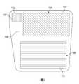
圖1繪示依據本揭示內容的一個實施例的波導結合器的平面圖。FIG. 1 shows a plan view of a waveguide coupler according to an embodiment of the present disclosure.
圖2繪示依據本揭示內容的一個實施例的成角度蝕刻系統的示意側視圖。FIG. 2 shows a schematic side view of an angled etching system according to an embodiment of the present disclosure.
圖3繪示依據本揭示內容的一個實施例的電極組件的側截面圖。FIG. 3 shows a side cross-sectional view of an electrode assembly according to an embodiment of the present disclosure.
圖4A繪示依據本揭示內容的一個實施例的分段離子源的示意側視圖。FIG. 4A shows a schematic side view of a segmented ion source according to an embodiment of the present disclosure.
圖4B繪示依據本揭示內容的一個實施例的分段離子源的示意側視圖。FIG. 4B shows a schematic side view of a segmented ion source according to an embodiment of the present disclosure.
圖4C繪示依據本揭示內容的一個實施例的分段離子源的示意側視圖。FIG. 4C shows a schematic side view of a segmented ion source according to an embodiment of the present disclosure.
圖5A繪示依據本揭示內容的一個實施例的過濾板的示意平面圖。FIG. 5A is a schematic plan view of a filter plate according to an embodiment of the present disclosure.
圖5B繪示依據本揭示內容的一個實施例的圖4C的分段離子源的示意側視圖,其中過濾板耦接到該分段離子源。FIG. 5B shows a schematic side view of the segmented ion source of FIG. 4C according to an embodiment of the present disclosure, wherein the filter plate is coupled to the segmented ion source.
圖6繪示依據本揭示內容的一個實施例的電子束蝕刻系統的示意橫截面圖。FIG. 6 is a schematic cross-sectional view of an electron beam etching system according to an embodiment of the present disclosure.
圖7A繪示依據本揭示內容的一個實施例在第一位置處在波導器上執行的成角度蝕刻處理。FIG. 7A illustrates an angled etching process performed on the waveguide at the first position according to an embodiment of the present disclosure.
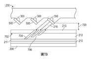
圖7B繪示依據本揭示內容的一個實施例在第二位置處的成角度蝕刻處理期間的圖7A的波導器。Figure 7B illustrates the waveguide of Figure 7A during an angled etching process at a second location in accordance with one embodiment of the present disclosure.
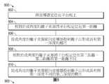
圖8繪示依據本揭示內容的一個實施例用於用成角度離子束來蝕刻波導器的方法的操作。FIG. 8 illustrates the operation of a method for etching a waveguide with an angled ion beam according to an embodiment of the present disclosure.
圖9繪示依據本揭示內容的一個實施例用於用成角度電子束來蝕刻波導器的方法的操作。FIG. 9 illustrates the operation of a method for etching a waveguide with an angled electron beam according to an embodiment of the present disclosure.
為了促進了解,已儘可能使用相同的參考標號來標誌該等圖式共有的相同元件。可以預期,可以在不另外詳述的情況下有益地將一個實施例的元件及特徵併入其他實施例。In order to promote understanding, the same reference numerals have been used as much as possible to identify the same elements common to the drawings. It is contemplated that the elements and features of one embodiment can be beneficially incorporated into other embodiments without further elaboration.
本揭示內容的態樣與用於製造奈米結構光學設備(例如波導器、波導結合器、成角度的光柵、及超透鏡)的裝置相關,該等光學設備用在各種設備(例如增強實境/虛擬實境(AR/VR)的頭戴裝置、及智慧型窗戶)中。在一個實例中,利用成角度的離子源來朝向基板投射離子以形成包括成角度的光柵的波導器。在另一個實例中,利用成角度的電子束源來朝向基板投射電子以形成包括成角度的光柵的波導器。本揭示內容的另外的態樣提供了用於利用成角度的離子束源及成角度的電子束源來在波導器上形成成角度光柵的方法。The aspect of the present disclosure is related to devices used to manufacture nanostructured optical devices (such as waveguides, waveguide couplers, angled gratings, and hyperlenses), which are used in various devices (such as augmented reality). /Virtual reality (AR/VR) headsets and smart windows).In one example, an angled ion source is used to project ions toward the substrate to form a waveguide that includes an angled grating. In another example, an angled electron beam source is used to project electrons toward the substrate to form a waveguide including an angled grating. Another aspect of the present disclosure provides a method for using an angled ion beam source and an angled electron beam source to form an angled grating on a waveguide.
圖1繪示依據本揭示內容的一個實施例的波導結合器100的平面圖。要了解,下文所述的波導結合器100是示例性的波導結合器,且具有不同設計的其他波導結合器可以受益於本文中所述的實施例。波導結合器100包括由複數個光柵108所界定的輸入耦合區域102、由複數個光柵110所界定的中間區域104、及由複數個光柵112所界定的輸出耦合區域106。輸入耦合區域102從微型顯示器接收具有一定強度的入射光束(虛擬影像)。該複數個光柵108中的每個光柵(例如鰭片結構等等)均將入射射束分離成複數個模式,每個射束均具有一個模式。零階模式(T0)射束經由波導結合器100回向反射或透射,正一階模式(T1)射束經由波導結合器100耦合到中間區域104,且負一階模式(T-1)射束在波導結合器100中在與T1射束相對的方向上傳播。理想上,入射射束被分離成具有入射射束的所有強度的T1射束以將虛擬影像引導到中間區域104。一種將入射射束分離成具有入射射束的所有強度的T1射束的方法是利用具有傾斜角的鰭片(其包括光柵108)來抑制T-1射束及T0射束。T1射束經由波導結合器100經歷全內反射(TIR),直到T1射束與中間區域104中的該複數個光柵110接觸為止。輸入耦合區域102的一部分可以具有帶有傾斜角的光柵108,該傾斜角與來自輸入耦合區域102的相鄰部分的光柵108的傾斜角不同。FIG. 1 shows a plan view of a
T1射束接觸該複數個光柵110的鰭片。T1射束被分離成在波導結合器100中回向折射或丟失的T0射束、在中間區域104中經歷TIR直到T1射束接觸該複數個光柵110的另一個鰭片為止的T1射束、及經由波導結合器100耦合到輸出耦合區域106的T-1射束。在中間區域104中經歷TIR的T1射束繼續接觸該複數個光柵110中的光柵,直到符合以下條件中的任一者為止:經由波導結合器100耦合到中間區域104的T1射束的強度耗盡,或傳播經由中間區域104的剩餘的T1射束到達中間區域104的端部。The T1 beam contacts the fins of the plurality of
該複數個光柵110被調整為控制穿過波導結合器100耦合到中間區域104的T1射束以控制耦合到輸出耦合區域106的T-1射束的強度,以從使用者的角度調變從微型顯示器產生的虛擬影像的視野及增加使用者可以檢視虛擬影像的視角。一種控制穿過波導結合器100耦合到中間區域104的T1射束的方法是最佳化該複數個光柵110的每個鰭片的傾斜角,以控制耦合到輸出耦合區域106的T-1射束的強度。中間區域104的一部分可以具有帶有傾斜角的光柵110,該傾斜角與來自中間區域104的相鄰部分的光柵110的傾斜角不同。並且,光柵110可以具有帶有傾斜角的鰭片,該等傾斜角與光柵108的鰭片的傾斜角不同。The plurality of
經由波導結合器100耦合到輸出耦合區域106的T-1射束在波導結合器100中經歷TIR,直到T-1射束接觸該複數個光柵112中的光柵為止,在該光柵處,T-1射束被分離成在波導結合器100中回向折射或丟失的T0射束。T1射束在輸出耦合區域106中經歷TIR,直到T1射束接觸該複數個光柵112的另一個鰭片且T-1射束從波導結合器100耦合出來為止。在輸出耦合區域106中經歷TIR的T1射束繼續接觸該複數個光柵112的鰭片,直到符合以條件中的任一者為止:經由波導結合器100耦合到輸出耦合區域106的T-1射束的強度耗盡,或傳播經由輸出耦合區域106的剩餘的T1射束已經到達輸出耦合區域106的端部。該複數個光柵112被調整為控制經由波導結合器100耦合到輸出耦合區域106的T-1射束以控制從波導結合器100耦合出來的T-1射束的強度,以進一步從使用者的角度調變從微型顯示器產生的虛擬影像的視野及進一步增加使用者可以檢視虛擬影像的視角。The T-1 beam coupled to the
一種控制經由波導結合器100耦合到輸出耦合區域106的T-1射束的方法是最佳化該複數個光柵112的每個鰭片的傾斜角以進一步調變視野及增加視角。中間區域104的一部分可以具有帶有鰭片傾斜角的光柵110,該鰭片傾斜角與來自中間區域104的相鄰部分的光柵110的鰭片傾斜角不同。並且,光柵112可以具有與光柵108及光柵110的鰭片傾斜角不同的鰭片傾斜角。One method of controlling the T-1 beam coupled to the
圖2繪示依據本揭示內容的一個實施例的成角度蝕刻系統200的示意側視圖。要了解,下文所述的成角度蝕刻系統200是示例性的成角度蝕刻系統,且可以將其他的成角度蝕刻系統與依據本揭示內容的實施例的波導結合器一起使用或修改為製造該等波導結合器。FIG. 2 shows a schematic side view of an
為了形成具有傾斜角的鰭片,藉由成角度蝕刻系統200來蝕刻設置在基板210上的光柵材料212。在一個實施例中,將光柵材料212設置在設置在基板210上的蝕刻停止層211上,且將圖案化的硬質掩模213設置在光柵材料212上方。基於每個鰭片的傾斜角
在可以與本文中所述的其他實施例結合的另一個實施例中,圖案化的硬質掩模213是不透明的硬質掩模,在波導結合器形成之後移除該不透明的硬質掩模。例如,不透明的硬質掩模包括反射材料,例如鉻、銀、氮化鈦、氮化鉭、氮化矽、或氧化矽材料。在另一個實施例中,圖案化的硬質掩模213是透明的硬質掩模。在可以與本文中所述的其他實施例結合的一個實施例中,蝕刻停止層211是不透明的蝕刻停止層,在波導結合器形成之後移除該不透明的蝕刻停止層。在可以與本文中所述的其他實施例結合的另一個實施例中,蝕刻停止層211是透明的蝕刻停止層。In another embodiment that can be combined with other embodiments described herein, the patterned
成角度蝕刻系統200包括收容離子束源204的離子束腔室202。離子束源204被配置為產生離子束216,例如點狀射束、帶狀射束、或全基板尺寸射束。離子束腔室202被配置為相對於基準面218用角度α引導離子束216,該基準面與基板210正交地定向。例如,系統200亦包括分段源230。分段源230調變離子束216的角度以實現用來在光柵材料212中製造鰭片的角度α。針對圖3及圖4A至圖4C詳細描述分段源230(其可以包括複數個節段,每個節段均包括一或更多個電極)。The
基板210固位在耦接到第一致動器208的平台板206上。第一致動器208(其可以是線性致動器、旋轉致動器、步進馬達等等)被配置為沿著y方向及/或z方向用掃描運動移動平台板206。在一個實施例中,第一致動器208更被配置為傾斜平台板206,使得基板210相對於離子束腔室202的x軸用傾斜角β定位。角度α及傾斜角β造成相對於基準面218的離子束角


圖3繪示依據本揭示內容的一個實施例的電極組件300的側截面圖。在一個實施例中,可以將電極組件300調適為漸變透鏡配置。在可以與其他實施例結合的另一個實施例中,電極組件300包括一或更多個電極組件。例如,電極組件300可以包括一組入口電極302、一或更多組抑制電極304(或聚焦電極)、及一組出口電極306。出口電極306可以稱為接地電極。可以將每組電極302、304、306定位為具有空間或間隙以允許離子束216(例如帶狀射束、點狀射束、或全基板尺寸射束)穿過該空間或該間隙。FIG. 3 shows a side cross-sectional view of an
在一些實施例中,入口電極302、抑制電極304、及出口電極306被提供在殼體308中。泵310可以直接或間接地連接到殼體308。泵310可以是用於提供高真空環境或不同壓力的其他受控環境的真空泵。例如,泵310可以在殼體308內產生亞大氣壓力環境,或泵310可以在殼體308內維持近似大氣的壓力環境。在可以與其他的實施例結合的其他的實施例中,殼體308可以包括一或更多個介電構件314。介電構件314用來將殼體308與電極組件300的其他部件電隔離。In some embodiments, the
該組入口電極302及出口電極306可以包括彼此電耦接的兩個導電片。在其他的實施例中,入口電極302組件是單件式結構,該結構具有孔以供離子束216穿過該孔。在一些實施例中,抑制電極304的上部及下部可以具有不同的電勢(例如在單獨/謹慎的導電部分中具有不同的電勢),以偏轉經過該等抑制電極的離子束216。雖然電極組件300被描繪為七(7)元件透鏡配置(例如具有五(5)組抑制電極304),但應理解,亦可以利用任何數量的元件(或電極)。例如,在一些實施例中,電極組件300可以利用一系列的三(3)到十(10)個電極組。The set of
可以藉由使用幾個薄電極(例如抑制電極304)來控制沿著離子束216的路徑的電勢漸變,以實現離子束216的靜電聚焦。其結果是,可以將輸入離子束216的使用用在可以允許較高品質的射束的能量範圍(例如100伏特到3,000伏特)中,即使對於非常低能量的輸出射束亦是如此。在一個實施例中,在離子束216穿過電極組件300的電極時,藉由電極組件300的電極,離子束216可以從6keV減速到0.2keV且用約15度到約30度(或更大)而偏轉。在一個實例中,能量比可以是30/1。Several thin electrodes (such as the suppression electrode 304) can be used to control the potential gradient along the path of the
應理解,可以藉由以下步驟中的一者或組合來完成分離及獨立控制減速、偏轉、及/或聚焦:相對於離子束216的中心射線軌跡線移動電極(例如入口電極302、抑制電極304、及出口電極306),及沿著離子束216的中心射線軌跡線(例如圖2的基準面218)變化偏轉電壓電極(例如入口電極302、抑制電極304、及出口電極306)以用偏轉角α在沿著中心射線軌跡線的每個點處反射射束能量。電極相對於離子束216的中心射線軌跡線的對稱性在於,可以將上電極及下電極最靠近離子束216的端部相對於離子束216的中心射線軌跡線保持相等(或接近相等)的垂直距離。例如,可以將離子束216上方及下方的電極上的電壓差配置為使得電場的偏轉分量可以是該點處的射束能量的固定比率/因數(其可以沿著電極或透鏡變化)。It should be understood that the separation and independent control of deceleration, deflection, and/or focusing can be accomplished by one or a combination of the following steps: moving electrodes (such as
圖4A繪示依據本揭示內容的一個實施例的分段離子源230的示意側視圖。分段離子源230耦接到離子束腔室202或用其他方式與該離子束腔室整合在一起,且分段離子源230的節段412被對準或用其他方式定位以接收來自射束源204的離子束216。FIG. 4A shows a schematic side view of a
分段離子源230包括殼體402,該殼體具有第一壁404、第二壁406、第三壁414、及第四壁416。在一個實施例中,第一壁404及第二壁406定向為彼此實質平行。第三壁414及第四壁416亦彼此實質平行,且延伸於第一壁404與第二壁406之間。雖然可以有益地採用壁404、406、414、416的上述定向,但可以預期,亦可以利用其他的壁配置。The
在一個實施例中,第一壁404耦接到離子束腔室202,且節段412定位在平台板206附近且與該平台板相對。節段412形成於第二壁406中且包括複數個表面408、410。第一表面408相對於由第二壁406所界定的基準面成角度。可以相對於由第二壁406所界定的基準面將第一表面408的角度選定為在約1度與約60度之間。因此,第一表面408從第二壁406延伸且傾斜到殼體402中且朝向第一壁404傾斜。In one embodiment, the
第二表面410延伸於第一表面408與第二壁406之間。第二表面410定向為與由第二壁406所界定的基準面實質正交。然而,可以預期,第二表面410可以相對於由第二壁406所界定的基準面用非正交的角度定向。雖然繪示了三個節段412,但可以預期,取決於所需要蝕刻的基板210的面積,亦可以利用較大或較小數量的節段412來調變離子束216。此外,可以預期,可以改變表面408、410相對於彼此的大小,以調變離子束216的角度特性。The
在一個實施例中,電極組件300定位在殼體402內且與第二壁406的第一表面408相鄰。例如,電極組件300可以耦接到殼體402內的第一表面408。如圖3中所描繪,電極組件300的殼體308可以包括一定的形狀,該形狀被選定為與第一表面408的角度匹配或交接。第一表面408亦可以在其中包括一或更多個開口418,該一或更多個開口位在電極組件300被定位為允許離子束216穿過第一表面408之處附近。類似地,第一壁404亦可以具有形成在其中的一或更多個開口420,且形成於第一壁404中的開口420可以與形成於第一表面408中的開口418或電極組件300中的一或兩者對準。因此,離子束216可以用與由第一壁404所界定的基準面實質正交的定向傳播穿過第一壁404,但用預定角度穿過第二壁406的第一表面408離開殼體402。In one embodiment, the
圖4B繪示依據本揭示內容的一個實施例的分段離子源230的示意側視圖。分段離子源230耦接到離子束腔室202或用其他方式與該離子束腔室整合在一起,且分段離子源230的節段412被對準或用其他方式定位以接收來自射束源204的離子束216。FIG. 4B shows a schematic side view of the
分段離子源230包括殼體422,該殼體具有第一壁424、第二壁426、第三壁434、及第四壁436。在一個實施例中,第一壁424及第二壁426定向為彼此實質平行。第三壁434及第四壁436亦彼此實質平行,且延伸於第一壁424與第二壁426之間。雖然可以有益地採用壁424、426、434、436的上述定向,但可以預期,亦可以利用其他的壁配置。The
在一個實施例中,第一壁424耦接到離子束腔室202,且節段412定位在平台板206附近且與該平台板相對。節段412形成於第二壁426中且包括複數個表面428、430、432。第一表面428相對於由第二壁426所界定的基準面成角度。可以相對於由第二壁426所界定的基準面將第一表面428的角度選定為在約1度與約60度之間。因此,第一表面428從第二壁426延伸且傾斜到殼體422中且朝向第一壁424傾斜。In one embodiment, the
第二表面430延伸於第一表面428與第三表面432之間。第二表面430定向為與由第二壁426所界定的基準面實質平行。然而,可以預期,第二表面430可以相對於由第二壁426所界定的基準面用非平行的角度定向。第三表面432從第二表面430向相鄰的第一表面428處的第二壁426延伸。第三表面432相對於由第二壁426所界定的基準面成角度。在一個實例中,第三表面432的角度與第一表面428的角度實質類似。或者,第三表面432的角度可以與第一表面428的角度不同。第二表面430的大小將第三表面432與第一表面428隔開。因此,可以預期,第一表面428可以用範圍較廣的角度定向以允許成角度地蝕刻基板210。此外,認為第三表面432相對於第一表面428的間隔及定向允許一次處理較大面積的基板210。雖然繪示了三個節段412,但可以預期,取決於所需要蝕刻的基板210的面積,亦可以利用較大或較小數量的節段412來調變離子束216。亦可以預期,可以改變表面428、430、432相對於彼此的大小,以調變離子束216的角度特性。The
在一個實施例中,電極組件300定位在殼體422內且與第二壁426的第一表面428相鄰。例如,電極組件300可以耦接到殼體422內的第一表面428。如圖3中所描繪,電極組件300的殼體308可以包括一定的形狀,該形狀被選定為與第一表面428的角度匹配或交接。第一表面428亦可以在其中包括一或更多個開口438,該一或更多個開口位在電極組件300被定位為允許離子束216穿過第一表面428之處附近。類似地,第一壁424亦可以具有形成在其中的一或更多個開口440,且形成於第一壁424中的開口440可以與形成於第一表面428中的開口438或電極組件300中的一或兩者對準。因此,離子束216可以用與由第一壁424所界定的基準面實質正交的定向傳播穿過第一壁424,但用預定角度穿過第二壁426的第一表面428離開殼體422。In one embodiment, the
圖4C繪示依據本揭示內容的一個實施例的分段離子源230的示意側視圖。分段離子源230耦接到離子束腔室202或用其他方式與該離子束腔室整合在一起,且分段離子源230的節段412被對準或用其他方式定位以接收來自射束源204的離子束216。FIG. 4C shows a schematic side view of the
分段離子源230包括殼體442,該殼體具有第一壁444、第二壁446、第三壁454、及第四壁456。在一個實施例中,第一壁444及第二壁446定向為彼此實質平行。第三壁454及第四壁456亦彼此實質平行,且延伸於第一壁444與第二壁446之間。雖然可以有益地採用壁444、446、454、456的上述定向,但可以預期,亦可以利用其他的壁配置。The
在一個實施例中,第一壁444耦接到離子束腔室202,且節段412定位在平台板206附近且與該平台板相對。節段412形成於第二壁446中且包括複數個表面448、450、452。第一表面428相對於由第二壁446所界定的基準面成角度。可以相對於由第二壁446所界定的基準面將第一表面448的角度選定為在約1度與約60度之間。In one embodiment, the
第二表面450延伸於第一表面448與第三表面452之間。第二表面450定向為與由第二壁446所界定的基準面實質平行。然而,可以預期,第二表面450可以相對於由第二壁446所界定的基準面用非平行的角度定向。第三表面452相對於由第二壁446所界定的基準面用非正交的角度從第二壁446延伸。在此實施例中,第三表面452用一定角度從第二壁446延伸出殼體422且背向第一壁444延伸。或者,第三表面452可以用與由第二壁446所界定的基準面正交的角度從第二壁446延伸。The
在一個實例中,第三表面452的角度與第一表面448的角度實質類似。或者,第三表面452的角度可以與第一表面448的角度不同。第二表面450的大小將第三表面452與第一表面448隔開。因此,可以預期,第一表面448可以用範圍較廣的角度定向以允許成角度地蝕刻基板210。此外,認為第三表面452相對於第一表面448的間隔及定向允許一次處理較大面積的基板210。雖然繪示了三個節段412,但可以預期,取決於所需要蝕刻的基板210的面積,亦可以利用較大或較小數量的節段412來調變離子束216。亦可以預期,可以改變表面448、450、452相對於彼此的大小,以調變離子束216的角度特性。In one example, the angle of the
在一個實施例中,電極組件300定位在殼體442內且與第二壁446的第一表面448相鄰。例如,電極組件300可以耦接到殼體442內的第一表面448。如圖3中所描繪,電極組件300的殼體308可以包括一定的形狀,該形狀被選定為與第一表面448的角度匹配或交接。第一表面448亦可以在其中包括一或更多個開口458,該一或更多個開口位在電極組件300被定位為允許離子束216穿過第一表面448之處附近。類似地,第一壁444亦可以具有形成在其中的一或更多個開口460,且形成於第一壁444中的開口460可以與形成於第一表面448中的開口458或電極組件300中的一或兩者對準。因此,離子束216可以用與由第一壁444所界定的基準面實質正交的定向傳播穿過第一壁444,但用預定角度穿過第二壁446的第一表面448離開殼體442。In one embodiment, the
耦接到離子束腔室202的分段離子源230利用節段412及電極組件300來調變由射束源204所產生的離子束216的角度。節段412及電極組件300可以用一定方式定位或用其他方式定向以允許成角度地蝕刻基板210。可以預期,分段離子源230本質上可以是模組化的,且可以將不同的分段離子源在離子束腔室202上互換以促進基板210的不同的成角度蝕刻輪廓。藉由減少與由致動器208、220所進行的平台板206的移動相關聯的變數,亦可以利用分段離子源230來減少與平台板206的移動相關聯的處理複雜度。亦可以與經由致動器208、220進行的平台板206的移動結合利用分段離子源230,以允許基板210的更複雜或精確的成角度蝕刻輪廓。The
圖5A繪示依據本揭示內容的一個實施例的過濾板500的示意平面圖。圖5B繪示依據本揭示內容的一個實施例的圖3C的分段離子源230的示意側視圖,其中過濾板500耦接到該分段離子源。過濾板500被調適為與分段離子源230交接及耦接,以調變穿過過濾板500的離子束216的強度或分佈。FIG. 5A shows a schematic plan view of a
過濾板500包括主體502,該主體具有形成在該主體中的複數個孔506、510、514。主體502由具有充足厚度的材料製造,該材料對離子束轟擊有抵抗性或惰性且防止離子穿過該材料。孔506、510、514延伸穿過主體502以形成開口,離子束216穿過該等開口。主體502的第一區域504包括第一複數個孔506。雖然第一區域504被繪示為佔據主體502的大約三分之一,但可以預期,第一區域504亦可以包括主體502的較大或較小部分。第一複數個孔506被繪示為實質圓形的,其中第一複數個孔506中相鄰的孔之間的分佈大約是均勻的。然而,可以利用第一複數個孔506的任何數量、形狀、定向、間隔、或佈置來調變穿過第一複數個孔506的離子束216的強度或分佈。The
主體502的第二區域508包括第二複數個孔510。雖然第二區域508被繪示為佔據主體502的大約三分之一,但可以預期,第二區域508亦可以包括主體502的較大或較小部分。第二複數個孔510被繪示為實質卵形的,其中第二複數個孔510中相鄰的孔之間的分佈大約是均勻的。然而,可以利用第二複數個孔510的任何數量、形狀、定向、間隔、或佈置來調變穿過第二複數個孔510的離子束216的強度或分佈。The
主體502的第三區域512包括第三複數個孔514。雖然第三區域512被繪示為佔據主體502的大約三分之一,但可以預期,第三區域512亦可以包括主體502的較大或較小部分。第三複數個孔514被繪示為實質圓形的,其中第三複數個孔514中相鄰的孔之間的分佈大約是均勻的。然而,可以利用第三複數個孔514的任何數量、形狀、定向、間隔、或佈置來調變穿過第三複數個孔514的離子束216的強度或分佈。The
在一個實例中,第一複數個孔506佔據第一區域504中的主體502的一定面積,該面積大於第二複數個孔510及/或第三複數個孔514中的任一者的面積。換言之,在與第二區域508及/或第三區域512相比時,穿過主體502的第一區域504的離子束216較不被阻擋。因此,穿過第一區域504的離子束216可以用較大的量及強度的離子接觸基板510的第一區域。第二區域508及第三區域512分別具有不同的孔510、514的佈置、間隔、及形狀,且調變穿過該第二區域及該第三區域的離子束216使得分別在該第二區域及該第三區域中接觸基板210的離子的量及強度與由第一區域504所調變的離子的量及強度不同。In one example, the first plurality of
在一個實例中,第一區域中的基板210上的成角度蝕刻輪廓由穿過第一複數個孔506的離子束216所產生,第二區域中的基板210上的成角度蝕刻輪廓由穿過第二複數個孔510的離子束216所產生,且第三區域中的基板210上的成角度蝕刻輪廓由穿過第三複數個孔514的離子束216所產生。形成於基板上的鰭片或光柵的不同的蝕刻輪廓由過濾板500的區域504、508、512所產生。可以預期,可以利用合併於過濾板500中的各種的孔設計、形狀、間隔、密度等等來調變離子束216特性,且因此在利用單個離子束腔室202及/或離子束源204的同時允許基板上的不同的成角度蝕刻輪廓。In one example, the angled etch profile on the
圖5B繪示依據本揭示內容的一個實施例的圖4C的分段離子源230的示意側視圖,其中過濾板500耦接到該分段離子源。過濾板500耦接到分段離子源230的第一表面448。可以將過濾板500藉由機械緊固裝置(例如螺栓、螺釘等等)耦接到第一表面448,或可以將該等過濾板整合到第一表面448中,使得第一表面448及過濾板500是單體結構。在一個實施例中,相對於由第二壁446所界定的基準面用一定角度設置過濾板500。電極組件300被設置在殼體442內且與第一表面448相鄰。進入開口460的離子束216藉由電極組件300調變、彎曲、或成角度,且成角度的離子束216穿過開口458,在該開口處,離子束216的強度及/或分佈被過濾板500調變。可以預期,已經被過濾板500調變的離子束216具有複數個不同的特性,取決於離子束216穿過過濾板500的哪個區域504、508、512,該等特性不同地蝕刻基板210。可以利用由過濾板500所允許的此類不同的蝕刻輪廓及特性來在基板210上蝕刻具有不同的深度或其他特性的鰭片或光柵。FIG. 5B shows a schematic side view of the
雖然圖4C的分段離子源230被繪示為具有過濾板500,但可以預期,亦可以有利地將過濾板500與圖4A及4B的分段離子源230結合利用。例如,過濾板500可以耦接到圖4A的分段離子源230的第一表面408,或過濾板500可以耦接到圖4B的分段離子源230的第一表面428。取決於分段離子源230的配置,可以用各種與所繪示的彼等定向不同的定向設置過濾板500及電極組件300。例如,可以分別將電極組件300及過濾板利用在圖4B及圖4C的分段離子源230的第三表面432、452的相對側上。Although the
圖6繪示依據本揭示內容的一個實施例的電子束蝕刻系統600的示意橫截面圖。電子束蝕刻系統600的一個實例是可以從加州聖克拉拉市的應用材料有限公司取得的SYM3TM裝置,可以依據本揭示內容的各種態樣修改該裝置。可以預期,來自其他製造商的其他合適的裝置亦可以受益於本文中所述的實施例。FIG. 6 shows a schematic cross-sectional view of an electron
系統600包括腔室主體602,該腔室主體包圍或用其他方式界定處理容積640。腔室主體602可以由合適的材料製造,例如不銹鋼、鋁、或上述項目的合金及組合。第一襯套636被設置在腔室主體602附近以保護腔室主體602免受處理容積640的處理環境影響。在一個實例中,第一襯套636可以由處理惰性或抵抗性材料製造,例如陶瓷材料或其他合適的材料,例如含矽材料、含碳材料、碳矽材料、或含氧化矽的材料。The
第二襯套638亦被設置在腔室主體602附近,且第二襯套638定位為實質環繞處理容積640。在一個實施例中,第二襯套638由介電材料製造,例如石英或陶瓷材料。在另一個實施例中,第二襯套638由與用來製造第一襯套636的彼等材料類似的材料製造。襯套636、638亦可以塗有與用來製造襯套636、638的彼等材料類似的各種材料,且可以額外塗有例如氧化鋁材料、氧化釔材料、或鋯材料的材料。在某些實施例中,第一襯套636及第二襯套638中的一或兩者是可選的。在此類實施例中,可以將腔室主體602製造及配置為在沒有襯套的情況下作用。The
排氣端口648形成穿過第二襯套636及腔室主體602。排氣端口648在設置在處理容積640中的托座604下方的位置處形成穿過第二襯套636及腔室主體602。泵650經由排氣端口648與處理容積640及環繞托座604的泵端口646流體連通。泵650允許從處理容積640排出材料。蓋616與腔室主體602耦接或用其他方式整合在一起且與托座604相對。The
托座604包括設置在該托座中的電極606。在一個實施例中,電極606是卡緊裝置(例如靜電卡盤),該卡緊裝置用於在基板614的處理期間將基板614固定到該卡緊裝置。導管610(例如電導管等等)耦接在電極606與電源612之間。可以利用來自電源612的電力來偏壓電極606以擇一將基板614卡緊到電極606或影響電子在基板614上的轟擊。電極606及導管610被絕緣材料608(例如介電材料)環繞,以將電極606及導管610與托座604電隔離。The
致動器644耦接到托座604且被配置為在處理容積640內升起及降下托座604。致動器644亦可以使得托座圍繞垂直軸旋轉。波紋管組件642圍繞托座604的延伸穿過腔室主體602的一部分設置,且波紋管組件642可操作來允許托座604垂直移動同時維持處理容積640的處理環境。例如,波紋管組件642可以可操作來在托座604升起或降下的同時在處理容積640內維持亞大氣壓力處理環境。The
第一氣體源630經由延伸穿過腔室主體602的第一導管628與處理容積640流體連通。在一個實施例中,第一氣體源630是向處理容積640供應惰性氣體(例如氬氣或氦氣)的惰性氣體源。第二氣體源634經由延伸穿過腔室主體602的第二導管632與處理容積640流體連通。在一個實施例中,第二氣體源634是向處理容積640供應處理氣體(例如含氯氣體、含氟氣體、含溴氣體、含氧氣體等等)的處理氣體源。The
在一個替代的實施例中,第一氣體源630及第二氣體源可以經由電極618與處理容積640流體連通。在此實施例中,導管628、632分別經由電極618耦接在氣體源630、634與處理容積640之間。例如,導管628、632可以延伸穿過電極618,或第二電極618可以包括複數個孔以用作氣體遞送淋噴頭。可以將孔設置在成角度的表面621上以提供從氣體源630、634進入處理容積640的氣體流動路徑。In an alternative embodiment, the
電極618耦接到蓋616,且電極618與電極606相對地定向。電極618包括分段表面620,該分段表面包括複數個成角度的表面621。在一個實施例中,用實質水平的定向將基板614設置在托座604的電極606上。在此類實施例中,成角度的表面621相對於基板614或電極606的主軸(水平線)中的任一者用成角度且非平行的定向來定向。在所繪示的實施例中,分段表面620的成角度的表面621跨電極618實質均勻。或者,分段表面620的成角度的表面621可以不均勻。例如,成角度的表面621可以具有不同的角度,或可以用不均勻的方式定位、隔開、或用其他方式定向,以允許製造具有不均勻的光柵的波導器。The
導管624(例如電導管等等)耦接在電極618與電源626之間。電極618及導管624被絕緣材料622(例如介電材料)環繞,以將電極618及導管624與蓋616電隔離。The catheter 624 (for example, an electric catheter, etc.) is coupled between the
操作時,藉由各種主體及表面處理(例如藉由電容耦合)來在處理容積640中產生電漿。在此實施例中,電源626是射頻(RF)電源。取決於所需的電子束特性,電源626可操作來產生具有約13.56MHz或約2MHz的頻率的RF電力。例如,用恆定或脈衝的方式向電極618施加RF電力,且相對於電極618偏壓電極606。在另一個實例中,向電極618施加RF電力且電極606保持不偏壓。據信,由電容耦合的電漿所產生的離子被電場所影響,該電場促進藉由由電漿所產生的離子進行的電極618的轟擊。可以依據本文中所述的實施例利用其他的電漿產生處理(例如空心陰極佈置、直流電極偏壓、或電子束電漿產生處理)。In operation, plasma is generated in the
電極618的離子轟擊能量及形成於處理容積640中的電漿的密度至少部分地藉由電源626(例如RF電源)來控制。認為電極618的離子轟擊會加熱電極618且使得電極618發射二次電子。在一個實施例中,電極618由具有高的二次電子發射係數的處理相容材料(例如矽、碳、碳矽材料、或氧化矽材料)製造。電極618亦可以由金屬氧化物材料製造,例如氧化鋁、氧化釔、或氧化鋯。The ion bombardment energy of the
高能二次電子(其具有負電荷)用受成角度的表面621影響的角度從分段表面620發射,且由於電極618的偏壓而背向電極618加速。在此實例中,電極618可以被負偏壓。分段表面620的成角度的表面621相對於由電極606所界定的水平基準面用約1°與約75°之間的角度定向。如此,電子束660相對於電極606及基板614用非正交的角度從電極618加速。High-energy secondary electrons (which have a negative charge) are emitted from the
來自電極618的分段表面620的高能電子的通量是電子束。電子束660的射束能量大約等於電極618的離子轟擊能量。在一個實施例中,電漿電勢大於電極618的電勢,且從電極618所發射的高能二次電子在電子束660的二次電子橫過形成於處理容積640中的電漿時進一步被電漿的鞘電壓加速。The flux of high-energy electrons from the
電子束660的至少一部分(包括由於分段表面620的高能離子轟擊而從電極618所發射的二次電子通量)傳播穿過處理容積640且接觸基板614以蝕刻基板614。在一個實施例中,除了電容產生的電漿以外,電子束660亦產生化學反應自由基及離子,該等化學反應自由基及離子可以吸附到基板614的表面且在基板614的表面上形成化學反應層。At least a portion of the electron beam 660 (including the secondary electron flux emitted from the
圖7A繪示依據本揭示內容的一個實施例在第一位置處執行在基板上的成角度蝕刻處理。基板210具有設置在該基板上的光柵材料212,且圖案化的硬質掩模213被設置在光柵材料212的表面702上。在所繪示的實施例中,基板210相對於分段離子源230(例如針對圖2-5B的離子束系統200所描述的分段離子源)定位在第一距離710。在另一個實施例中,可以藉由系統600來處理基板210,該系統利用電極618的分段表面620來產生電子束以蝕刻光柵材料212。FIG. 7A illustrates an angled etching process performed on the substrate at a first position according to an embodiment of the present disclosure. The
相對於基板210的主軸用非正交的角度朝向基板210引導離子束216(或電子束660)。圖案化的抗蝕劑213暴露光柵材料212的表面702處的某些區域,該等區域被離子束216或電子束660蝕刻。其結果是,凹口704及鰭片706形成於光柵材料212中。雖然僅繪示了兩個鰭片706及三個凹口704,但取決於要製造的波導器所需的光柵設計,亦可以蝕刻整個光柵材料212或該光柵材料的所需部分以形成凹口704及鰭片706。鰭片706及凹口704共同包括光柵。The ion beam 216 (or the electron beam 660) is guided toward the
圖7B繪示依據本揭示內容的一個實施例在第二位置處的成角度蝕刻處理期間的圖7A的基板210。第二位置將基板210相對於分段離子源230(或電極618的分段表面620)定位在第二距離720。在一個實施例中,第二距離720小於第一距離710。在另一個實施例中,第二距離720大於第一距離710。取決於所利用的裝置200、600,基板210可以藉由平台板206或托座604從第一距離710升高到第二距離720。藉由改變距離,改變了蝕刻及射束暴露特性,此造成光柵材料212的不同的蝕刻輪廓。例如,某些凹口704可以從表面702更深地延伸到光柵材料212中,而其他凹口則較淺。因此,鰭片706可以具有不同的大小,且可以調變傳播穿過波導器的光。FIG. 7B illustrates the
圖8繪示依據本揭示內容的一個實施例用於用成角度離子束來蝕刻波導器的方法800的操作。在操作802處,將波導器(或要製造成波導器的基板,例如基板216)定位在平台板上。在一個實例中,將波導器定位在平台板206上。在操作804處,相對於成角度的離子束源將平台板定位在第一距離。例如,相對於分段離子源230將平台板206定位在第一距離710。FIG. 8 illustrates the operation of a
在操作806處,從成角度的離子束源朝向波導器投射離子以形成具有第一深度的鰭片。在操作808處,相對於成角度的離子束源將平台板定位在第二距離。第二距離與第一距離不同。在一個實例中,相對於分段離子源230將平台板206定位在第二距離720。在操作810處,從成角度的離子束源朝向波導器投射離子以形成具有與第一深度不同的第二深度的鰭片。鰭片706的深度涉及鰭片706延伸到光柵材料212中的距離且亦與凹口704的深度相關。在一個實施例中,第二深度大於第一深度。在另一個實施例中,第二深度小於第一深度。At
圖9繪示依據本揭示內容的一個實施例用於用成角度電子束來蝕刻波導器的方法900的操作。在操作902處,將波導器(或要製造成波導器的基板,例如基板216)定位在平台板上。在一個實例中,將波導器定位在托座604上。在操作904處,相對於成角度的電子束源將平台板定位在第一距離。例如,相對於電極618的分段表面620將托座604定位在第一距離710。FIG. 9 illustrates the operation of a
在操作906處,從成角度的電子束源朝向波導器投射電子以形成具有第一深度的鰭片。在操作908處,相對於成角度的電子束源將平台板定位在第二距離。第二距離與第一距離不同。在一個實例中,相對於電極618的分段表面620將托座604定位在第二距離720。在操作910處,從成角度的電子束源朝向波導器投射電子以形成具有與第一深度不同的第二深度的鰭片。鰭片706的深度涉及鰭片706延伸到光柵材料212中的距離且亦與凹口704的深度相關。在一個實施例中,第二深度大於第一深度。在另一個實施例中,第二深度小於第一深度。At
方法800、900分別允許利用離子束及電子束來進行波導器製造。可以預期,方法800、900可以利用單個蝕刻循環或多個蝕刻循環。在一個實例中,可以執行45°的成角度蝕刻處理約14次,每次的持續時間為約300秒。在此實例中,用約3nm/分鐘的蝕刻速率形成約240nm深的凹口。在另一個實例中,可以執行60°的成角度蝕刻處理達約18次,每次的持續時間為約300秒。在此實例中,用約1.8nm/分鐘的蝕刻速率形成約190nm深的凹口。然而,可以預期,取決於離子束或電子束蝕刻處理的處理變數及所需的蝕刻角度,本文中所述的裝置及方法可以允許高達約50nm/分鐘的蝕刻速率。
可以將方法800、900用於實質上整個基板表面上的毯式基板蝕刻,或在相對於其他區域優先蝕刻基板的指定區域時用於更局部的蝕刻處理。分段離子源230及電極618的分段表面620分別允許改善離子束及電子束的成角度蝕刻效率。亦可以預期,可以將分段離子源230及電極618的分段表面620交換出它們相應的系統200、600以更高效地改變波導器的蝕刻輪廓,該等蝕刻輪廓實現具有複數個鰭片高度及凹口或溝槽深度或具有不同角度的光柵的光柵。The
雖然以上內容是針對本揭示內容的實施例,但亦可以在不脫離本揭示內容的基本範圍的情況下設計本揭示內容的其他的及另外的實施例,且本揭示內容的範圍是由隨後的請求項所決定的。Although the above content is directed to the embodiments of the present disclosure, other and other embodiments of the present disclosure can also be designed without departing from the basic scope of the present disclosure, and the scope of the present disclosure is determined by the following Determined by the request.
600:電子束蝕刻系統600: Electron beam etching system
602:腔室主體602: Chamber body
604:托座604: Bracket
606:電極606: Electrode
608:絕緣材料608: insulating material
610:導管610: Catheter
612:電源612: Power
614:基板614: Substrate
616:蓋616: cover
618:電極618: Electrode
620:分段表面620: segmented surface
621:成角度的表面621: Angled Surface
622:絕緣材料622: insulating material
624:導管624: Catheter
626:電源626: Power
628:第一導管628: first catheter
630:第一氣體源630: First gas source
632:第二導管632: second catheter
634:第二氣體源634: second gas source
636:第一襯套636: first bush
638:第二襯套638: second bush
640:處理容積640: processing volume
642:波紋管組件642: bellows assembly
644:致動器644: Actuator
646:泵端口646: pump port
648:排氣端口648: exhaust port
650:泵650: Pump
660:電子束660: electron beam
Claims (20)
Translated fromChineseApplications Claiming Priority (4)
| Application Number | Priority Date | Filing Date | Title |
|---|---|---|---|
| US201862780792P | 2018-12-17 | 2018-12-17 | |
| US201862780805P | 2018-12-17 | 2018-12-17 | |
| US62/780,792 | 2018-12-17 | ||
| US62/780,805 | 2018-12-17 |
Publications (2)
| Publication Number | Publication Date |
|---|---|
| TW202036062A TW202036062A (en) | 2020-10-01 |
| TWI730548Btrue TWI730548B (en) | 2021-06-11 |
Family
ID=71071206
Family Applications (5)
| Application Number | Title | Priority Date | Filing Date |
|---|---|---|---|
| TW108146250ATWI730548B (en) | 2018-12-17 | 2019-12-17 | Electron beam apparatus for optical device fabrication |
| TW108146266ATWI755663B (en) | 2018-12-17 | 2019-12-17 | Methods of optical device fabrication using an electron beam apparatus |
| TW108146252ATWI708082B (en) | 2018-12-17 | 2019-12-17 | Methods of optical device fabrication using an ion beam source |
| TW111101227ATWI826899B (en) | 2018-12-17 | 2019-12-17 | Methods of optical device fabrication using an electron beam apparatus |
| TW108146247ATWI729629B (en) | 2018-12-17 | 2019-12-17 | Etching apparatus |
Family Applications After (4)
| Application Number | Title | Priority Date | Filing Date |
|---|---|---|---|
| TW108146266ATWI755663B (en) | 2018-12-17 | 2019-12-17 | Methods of optical device fabrication using an electron beam apparatus |
| TW108146252ATWI708082B (en) | 2018-12-17 | 2019-12-17 | Methods of optical device fabrication using an ion beam source |
| TW111101227ATWI826899B (en) | 2018-12-17 | 2019-12-17 | Methods of optical device fabrication using an electron beam apparatus |
| TW108146247ATWI729629B (en) | 2018-12-17 | 2019-12-17 | Etching apparatus |
Country Status (7)
| Country | Link |
|---|---|
| US (5) | US11810755B2 (en) |
| EP (4) | EP3900008A4 (en) |
| JP (4) | JP7555340B2 (en) |
| KR (4) | KR20210094117A (en) |
| CN (4) | CN113242989A (en) |
| TW (5) | TWI730548B (en) |
| WO (4) | WO2020131848A1 (en) |
Families Citing this family (8)
| Publication number | Priority date | Publication date | Assignee | Title |
|---|---|---|---|---|
| KR102535740B1 (en)* | 2018-06-28 | 2023-05-26 | 어플라이드 머티어리얼스, 인코포레이티드 | Fabrication of diffraction gratings |
| EP4481469A3 (en)* | 2018-11-07 | 2025-02-26 | Applied Materials, Inc. | Formation of angled gratings |
| US10991547B2 (en)* | 2019-09-25 | 2021-04-27 | Applied Materials, Inc. | Method and device for a carrier proximity mask |
| US12109641B2 (en) | 2020-11-17 | 2024-10-08 | Applied Materials, Inc. | Optical device having structural and refractive index gradation, and method of fabricating the same |
| US12027426B2 (en) | 2021-01-29 | 2024-07-02 | Applied Materials, Inc. | Image-based digital control of plasma processing |
| KR20240073158A (en)* | 2021-10-15 | 2024-05-24 | 어플라이드 머티어리얼스, 인코포레이티드 | Partially metallized gratings as high-performance waveguide incouplers |
| EP4453652A1 (en) | 2021-12-22 | 2024-10-30 | Applied Materials, Inc. | Method for forming multi-depth optical devices |
| JP2025531663A (en)* | 2022-08-26 | 2025-09-25 | プレイザー アイピー、エルエルシー | Improved plasma products and methods for producing improved plasma products using multiple simultaneous discharges - Patents.com |
Citations (5)
| Publication number | Priority date | Publication date | Assignee | Title |
|---|---|---|---|---|
| US20080317968A1 (en)* | 2005-04-25 | 2008-12-25 | Varian Semiconductor Equipment Associates, Inc. | Tilted plasma doping |
| US20160064260A1 (en)* | 2014-08-29 | 2016-03-03 | Lam Research Corporation | Ion injector and lens system for ion beam milling |
| US20160276134A1 (en)* | 2015-03-17 | 2016-09-22 | Applied Materials, Inc. | Ion-ion plasma atomic layer etch process and reactor |
| TW201635325A (en)* | 2015-02-13 | 2016-10-01 | Hitachi High Tech Corp | Plasma ion source and charged particle beam apparatus |
| CN107293468A (en)* | 2013-07-08 | 2017-10-24 | 朗姆研究公司 | Ion beam etching system |
Family Cites Families (65)
| Publication number | Priority date | Publication date | Assignee | Title |
|---|---|---|---|---|
| US4240448A (en) | 1978-08-21 | 1980-12-23 | Hauni-Werke Korber & Co. Kg | Apparatus for increasing the permeability of wrapping material for rod-shaped smokers' products |
| US5116461A (en)* | 1991-04-22 | 1992-05-26 | Motorola, Inc. | Method for fabricating an angled diffraction grating |
| JPH05314940A (en)* | 1992-05-08 | 1993-11-26 | Hitachi Ltd | Ion source of ion beam application apparatus |
| JPH06201909A (en)* | 1992-12-28 | 1994-07-22 | Canon Inc | Production of diffraction grating |
| US5375456A (en) | 1993-11-18 | 1994-12-27 | Trw Vehicle Safety Systems Inc. | Leak testing apparatus and method |
| JP3768547B2 (en)* | 1993-12-17 | 2006-04-19 | キヤノン株式会社 | Double-sided film formation method |
| US5981899A (en)* | 1997-01-17 | 1999-11-09 | Balzers Aktiengesellschaft | Capacitively coupled RF-plasma reactor |
| US6211628B1 (en)* | 1997-08-02 | 2001-04-03 | Corning Incorporated | System for controlling the position of an electron beam in a cathode ray tube and method thereof |
| KR19990047679A (en) | 1997-12-05 | 1999-07-05 | 박호군 | Apparatus for Surface Treatment of Materials Using Ion Beams |
| JP4283432B2 (en)* | 2000-11-06 | 2009-06-24 | 株式会社日立製作所 | Sample preparation equipment |
| US7546016B2 (en)* | 2001-06-28 | 2009-06-09 | E-Beam & Light, Inc. | Optical elements formed by inducing changes in the index of refraction by utilizing electron beam radiation |
| GB2386247B (en)* | 2002-01-11 | 2005-09-07 | Applied Materials Inc | Ion beam generator |
| DE10234614B3 (en) | 2002-07-24 | 2004-03-04 | Fractal Ag | Process for processing carrier material by heavy ion radiation and subsequent etching process |
| JP2004363085A (en)* | 2003-05-09 | 2004-12-24 | Ebara Corp | Inspection apparatus by charged particle beam and method for manufacturing device using inspection apparatus |
| KR20060003591A (en)* | 2004-07-07 | 2006-01-11 | 주성엔지니어링(주) | Plasma processing apparatus comprising a plasma electrode having a plurality of protrusions |
| US7780821B2 (en) | 2004-08-02 | 2010-08-24 | Seagate Technology Llc | Multi-chamber processing with simultaneous workpiece transport and gas delivery |
| KR100851901B1 (en)* | 2005-01-07 | 2008-08-13 | 삼성전자주식회사 | Apparatus for extraction ion beam |
| KR100702010B1 (en)* | 2005-03-07 | 2007-03-30 | 삼성전자주식회사 | Reflector, substrate processing apparatus employing same, and substrate processing method using same |
| WO2007067296A2 (en) | 2005-12-02 | 2007-06-14 | Alis Corporation | Ion sources, systems and methods |
| EP2033040B1 (en) | 2006-06-02 | 2020-04-29 | Magic Leap, Inc. | Stereoscopic exit pupil expander display |
| JP2008117753A (en) | 2006-10-12 | 2008-05-22 | Tdk Corp | Ion gun, ion beam etching device, ion beam etching equipment, etching method and manufacturing method of magnetic recording medium |
| JP5055011B2 (en) | 2007-04-23 | 2012-10-24 | 株式会社日立ハイテクノロジーズ | Ion source |
| US7723699B2 (en)* | 2007-06-26 | 2010-05-25 | Varian Semiconductor Equipment Associates, Inc. | Cathode having electron production and focusing grooves, ion source and related method |
| US20090084501A1 (en)* | 2007-09-27 | 2009-04-02 | Tokyo Electron Limited | Processing system for producing a negative ion plasma |
| US7915597B2 (en)* | 2008-03-18 | 2011-03-29 | Axcelis Technologies, Inc. | Extraction electrode system for high current ion implanter |
| US20090236214A1 (en)* | 2008-03-20 | 2009-09-24 | Karthik Janakiraman | Tunable ground planes in plasma chambers |
| US8986558B2 (en) | 2008-09-01 | 2015-03-24 | Japan Science And Technology Agency | Plasma etching method, plasma etching device, and method for producing photonic crystal |
| US20120104274A1 (en)* | 2009-07-16 | 2012-05-03 | Canon Anelva Corporation | Ion beam generating apparatus, substrate processing apparatus and method of manufacturing electronic device |
| US20110065282A1 (en) | 2009-09-11 | 2011-03-17 | General Electric Company | Apparatus and methods to form a patterned coating on an oled substrate |
| US8173527B2 (en) | 2009-10-19 | 2012-05-08 | Varian Semiconductor Equipment Associates, Inc. | Stepped masking for patterned implantation |
| US8129695B2 (en)* | 2009-12-28 | 2012-03-06 | Varian Semiconductor Equipment Associates, Inc. | System and method for controlling deflection of a charged particle beam within a graded electrostatic lens |
| CN102360093A (en)* | 2011-10-19 | 2012-02-22 | 苏州大学 | Holographic blazed grating manufacturing method |
| US9926627B2 (en) | 2011-12-21 | 2018-03-27 | Applied Materials, Inc. | System and methods for processing a substrate |
| WO2013118517A1 (en)* | 2012-02-10 | 2013-08-15 | 国立大学法人東北大学 | Electron beam generating appartus, electron beam irradaition apparatus, multi-electron beam irradiation apparatus, electron beam exposure apparatus, electron beam irradiation method, and manufacture method |
| US8984451B2 (en)* | 2013-02-22 | 2015-03-17 | Aselta Nanographics | Free form fracturing method for electronic or optical lithography |
| US9288889B2 (en)* | 2013-03-13 | 2016-03-15 | Varian Semiconductor Equipment Associates, Inc. | Apparatus and techniques for energetic neutral beam processing |
| US9245761B2 (en) | 2013-04-05 | 2016-01-26 | Lam Research Corporation | Internal plasma grid for semiconductor fabrication |
| JP6348321B2 (en)* | 2013-05-17 | 2018-06-27 | キヤノンアネルバ株式会社 | Etching device |
| TWI690968B (en)* | 2014-03-07 | 2020-04-11 | 美商應用材料股份有限公司 | Grazing angle plasma processing for modifying a substrate surface |
| US9287123B2 (en)* | 2014-04-28 | 2016-03-15 | Varian Semiconductor Equipment Associates, Inc. | Techniques for forming angled structures for reduced defects in heteroepitaxy of semiconductor films |
| US9534289B2 (en)* | 2014-06-18 | 2017-01-03 | Applied Materials, Inc. | Plasma process chambers employing distribution grids having focusing surfaces thereon enabling angled fluxes to reach a substrate, and related methods |
| US9343312B2 (en) | 2014-07-25 | 2016-05-17 | Taiwan Semiconductor Manufacturing Company, Ltd. | High temperature intermittent ion implantation |
| US20160035539A1 (en)* | 2014-07-30 | 2016-02-04 | Lauri SAINIEMI | Microfabrication |
| US9304235B2 (en)* | 2014-07-30 | 2016-04-05 | Microsoft Technology Licensing, Llc | Microfabrication |
| JP6403485B2 (en)* | 2014-08-08 | 2018-10-10 | 住友重機械イオンテクノロジー株式会社 | Ion implantation apparatus and ion implantation method |
| US10825652B2 (en)* | 2014-08-29 | 2020-11-03 | Lam Research Corporation | Ion beam etch without need for wafer tilt or rotation |
| US9659797B1 (en)* | 2014-09-17 | 2017-05-23 | Sandia Corporation | Wafer scale oblique angle plasma etching |
| US9536748B2 (en)* | 2014-10-21 | 2017-01-03 | Lam Research Corporation | Use of ion beam etching to generate gate-all-around structure |
| KR101943553B1 (en)* | 2014-11-25 | 2019-04-18 | 삼성전자주식회사 | Method of forming a pattern using ion beams of bilateral symmetry, method of forming a magnetic memory device using the same, and ion beam apparatus generation ion beams of bilateral symmetry |
| US9478399B2 (en)* | 2015-03-27 | 2016-10-25 | Varian Semiconductor Equipment Associates, Inc. | Multi-aperture extraction system for angled ion beam |
| US9697988B2 (en)* | 2015-10-14 | 2017-07-04 | Advanced Ion Beam Technology, Inc. | Ion implantation system and process |
| US9812349B2 (en) | 2015-12-01 | 2017-11-07 | Lam Research Corporation | Control of the incidence angle of an ion beam on a substrate |
| KR102341688B1 (en)* | 2016-01-26 | 2021-12-21 | 한국전자통신연구원 | Field emission device and x-ray emission source having the same |
| US10249495B2 (en)* | 2016-06-28 | 2019-04-02 | Applied Materials, Inc. | Diamond like carbon layer formed by an electron beam plasma process |
| DE102016111998B4 (en)* | 2016-06-30 | 2024-01-18 | Infineon Technologies Ag | Forming electrode trenches using a directed ion beam and semiconductor device with trench electrode structures |
| US10141161B2 (en) | 2016-09-12 | 2018-11-27 | Varian Semiconductor Equipment Associates, Inc. | Angle control for radicals and reactive neutral ion beams |
| JP6972121B2 (en)* | 2016-10-05 | 2021-11-24 | マジック リープ, インコーポレイテッドMagic Leap, Inc. | Processing of non-uniform diffraction gratings |
| JP6746224B2 (en)* | 2016-11-18 | 2020-08-26 | 株式会社ディスコ | Device chip package manufacturing method |
| KR102673632B1 (en)* | 2016-12-06 | 2024-06-13 | 삼성전자주식회사 | Ion beam apparatus including slit structure for extracting ion beam, and etching method and method for forming magnetic memory device using the same |
| KR102768880B1 (en) | 2017-01-11 | 2025-02-19 | 삼성전자주식회사 | Method of forming patterns of semiconductor device |
| US10544505B2 (en)* | 2017-03-24 | 2020-01-28 | Applied Materials, Inc. | Deposition or treatment of diamond-like carbon in a plasma reactor |
| US10222202B2 (en) | 2017-05-25 | 2019-03-05 | Varian Semiconductor Equipment Associates, Inc. | Three dimensional structure fabrication control using novel processing system |
| WO2018226481A1 (en)* | 2017-06-05 | 2018-12-13 | Applied Materials, Inc. | Waveguide fabrication with sacrificial sidewall spacers |
| KR102641752B1 (en)* | 2018-11-21 | 2024-03-04 | 삼성전자주식회사 | Gas injection module, substrate processing apparatus and method for manufacturing semiconductor device using the same |
| US20200321186A1 (en)* | 2019-04-02 | 2020-10-08 | Applied Materials, Inc. | Method and apparatus for angled etching |
- 2019
- 2019-12-17TWTW108146250Apatent/TWI730548B/enactive
- 2019-12-17USUS16/717,211patent/US11810755B2/enactiveActive
- 2019-12-17WOPCT/US2019/066806patent/WO2020131848A1/ennot_activeCeased
- 2019-12-17CNCN201980083897.XApatent/CN113242989A/enactivePending
- 2019-12-17JPJP2021533444Apatent/JP7555340B2/enactiveActive
- 2019-12-17KRKR1020217022379Apatent/KR20210094117A/enactivePending
- 2019-12-17KRKR1020217022375Apatent/KR102842144B1/enactiveActive
- 2019-12-17JPJP2021533786Apatent/JP7447119B2/enactiveActive
- 2019-12-17EPEP19901270.9Apatent/EP3900008A4/enactivePending
- 2019-12-17JPJP2021533791Apatent/JP7410951B2/enactiveActive
- 2019-12-17USUS16/716,965patent/US11462386B2/enactiveActive
- 2019-12-17CNCN201980083890.8Apatent/CN113227859B/enactiveActive
- 2019-12-17TWTW108146266Apatent/TWI755663B/enactive
- 2019-12-17USUS16/717,400patent/US11640898B2/enactiveActive
- 2019-12-17WOPCT/US2019/066797patent/WO2020131843A1/ennot_activeCeased
- 2019-12-17USUS16/716,954patent/US10818472B2/enactiveActive
- 2019-12-17KRKR1020217022376Apatent/KR20210094116A/enactivePending
- 2019-12-17KRKR1020217022389Apatent/KR102841149B1/enactiveActive
- 2019-12-17WOPCT/US2019/066789patent/WO2020131839A1/ennot_activeCeased
- 2019-12-17CNCN201980083749.8Apatent/CN113196123B/enactiveActive
- 2019-12-17TWTW108146252Apatent/TWI708082B/enactive
- 2019-12-17WOPCT/US2019/066780patent/WO2020131831A1/ennot_activeCeased
- 2019-12-17EPEP19898594.7Apatent/EP3899614A4/enactivePending
- 2019-12-17JPJP2021533442Apatent/JP7447118B2/enactiveActive
- 2019-12-17TWTW111101227Apatent/TWI826899B/enactive
- 2019-12-17TWTW108146247Apatent/TWI729629B/enactive
- 2019-12-17CNCN201980083747.9Apatent/CN113196442B/enactiveActive
- 2019-12-17EPEP19900535.6Apatent/EP3899617B1/enactiveActive
- 2019-12-17EPEP19900534.9Apatent/EP3899615A4/enactivePending
- 2020
- 2020-10-26USUS17/080,802patent/US11430634B2/enactiveActive
Patent Citations (5)
| Publication number | Priority date | Publication date | Assignee | Title |
|---|---|---|---|---|
| US20080317968A1 (en)* | 2005-04-25 | 2008-12-25 | Varian Semiconductor Equipment Associates, Inc. | Tilted plasma doping |
| CN107293468A (en)* | 2013-07-08 | 2017-10-24 | 朗姆研究公司 | Ion beam etching system |
| US20160064260A1 (en)* | 2014-08-29 | 2016-03-03 | Lam Research Corporation | Ion injector and lens system for ion beam milling |
| TW201635325A (en)* | 2015-02-13 | 2016-10-01 | Hitachi High Tech Corp | Plasma ion source and charged particle beam apparatus |
| US20160276134A1 (en)* | 2015-03-17 | 2016-09-22 | Applied Materials, Inc. | Ion-ion plasma atomic layer etch process and reactor |
Also Published As
Similar Documents
| Publication | Publication Date | Title |
|---|---|---|
| TWI730548B (en) | Electron beam apparatus for optical device fabrication |