TWI729966B - Power management system - Google Patents
Power management systemDownload PDFInfo
- Publication number
- TWI729966B TWI729966BTW109143876ATW109143876ATWI729966BTW I729966 BTWI729966 BTW I729966BTW 109143876 ATW109143876 ATW 109143876ATW 109143876 ATW109143876 ATW 109143876ATW I729966 BTWI729966 BTW I729966B
- Authority
- TW
- Taiwan
- Prior art keywords
- current
- power
- protector
- management system
- parallel
- Prior art date
Links
Images

Classifications
- G—PHYSICS
- G01—MEASURING; TESTING
- G01R—MEASURING ELECTRIC VARIABLES; MEASURING MAGNETIC VARIABLES
- G01R31/00—Arrangements for testing electric properties; Arrangements for locating electric faults; Arrangements for electrical testing characterised by what is being tested not provided for elsewhere
- G01R31/40—Testing power supplies
- G01R31/42—AC power supplies
- H—ELECTRICITY
- H02—GENERATION; CONVERSION OR DISTRIBUTION OF ELECTRIC POWER
- H02H—EMERGENCY PROTECTIVE CIRCUIT ARRANGEMENTS
- H02H7/00—Emergency protective circuit arrangements specially adapted for specific types of electric machines or apparatus or for sectionalised protection of cable or line systems, and effecting automatic switching in the event of an undesired change from normal working conditions
- H02H7/26—Sectionalised protection of cable or line systems, e.g. for disconnecting a section on which a short-circuit, earth fault, or arc discharge has occured
- H—ELECTRICITY
- H02—GENERATION; CONVERSION OR DISTRIBUTION OF ELECTRIC POWER
- H02H—EMERGENCY PROTECTIVE CIRCUIT ARRANGEMENTS
- H02H9/00—Emergency protective circuit arrangements for limiting excess current or voltage without disconnection
- H02H9/04—Emergency protective circuit arrangements for limiting excess current or voltage without disconnection responsive to excess voltage
- H02H9/042—Emergency protective circuit arrangements for limiting excess current or voltage without disconnection responsive to excess voltage comprising means to limit the absorbed power or indicate damaged over-voltage protection device
- G—PHYSICS
- G01—MEASURING; TESTING
- G01R—MEASURING ELECTRIC VARIABLES; MEASURING MAGNETIC VARIABLES
- G01R31/00—Arrangements for testing electric properties; Arrangements for locating electric faults; Arrangements for electrical testing characterised by what is being tested not provided for elsewhere
- G01R31/12—Testing dielectric strength or breakdown voltage ; Testing or monitoring effectiveness or level of insulation, e.g. of a cable or of an apparatus, for example using partial discharge measurements; Electrostatic testing
- G—PHYSICS
- G01—MEASURING; TESTING
- G01R—MEASURING ELECTRIC VARIABLES; MEASURING MAGNETIC VARIABLES
- G01R15/00—Details of measuring arrangements of the types provided for in groups G01R17/00 - G01R29/00, G01R33/00 - G01R33/26 or G01R35/00
- G01R15/14—Adaptations providing voltage or current isolation, e.g. for high-voltage or high-current networks
- G01R15/20—Adaptations providing voltage or current isolation, e.g. for high-voltage or high-current networks using galvano-magnetic devices, e.g. Hall-effect devices, i.e. measuring a magnetic field via the interaction between a current and a magnetic field, e.g. magneto resistive or Hall effect devices
- G01R15/202—Adaptations providing voltage or current isolation, e.g. for high-voltage or high-current networks using galvano-magnetic devices, e.g. Hall-effect devices, i.e. measuring a magnetic field via the interaction between a current and a magnetic field, e.g. magneto resistive or Hall effect devices using Hall-effect devices
- G—PHYSICS
- G01—MEASURING; TESTING
- G01R—MEASURING ELECTRIC VARIABLES; MEASURING MAGNETIC VARIABLES
- G01R19/00—Arrangements for measuring currents or voltages or for indicating presence or sign thereof
- G01R19/0092—Arrangements for measuring currents or voltages or for indicating presence or sign thereof measuring current only
- G—PHYSICS
- G01—MEASURING; TESTING
- G01R—MEASURING ELECTRIC VARIABLES; MEASURING MAGNETIC VARIABLES
- G01R19/00—Arrangements for measuring currents or voltages or for indicating presence or sign thereof
- G01R19/165—Indicating that current or voltage is either above or below a predetermined value or within or outside a predetermined range of values
- G01R19/16566—Circuits and arrangements for comparing voltage or current with one or several thresholds and for indicating the result not covered by subgroups G01R19/16504, G01R19/16528, G01R19/16533
- G—PHYSICS
- G08—SIGNALLING
- G08B—SIGNALLING OR CALLING SYSTEMS; ORDER TELEGRAPHS; ALARM SYSTEMS
- G08B21/00—Alarms responsive to a single specified undesired or abnormal condition and not otherwise provided for
- G08B21/18—Status alarms
- G08B21/182—Level alarms, e.g. alarms responsive to variables exceeding a threshold
- G—PHYSICS
- G08—SIGNALLING
- G08B—SIGNALLING OR CALLING SYSTEMS; ORDER TELEGRAPHS; ALARM SYSTEMS
- G08B21/00—Alarms responsive to a single specified undesired or abnormal condition and not otherwise provided for
- G08B21/18—Status alarms
- G08B21/185—Electrical failure alarms
- H—ELECTRICITY
- H02—GENERATION; CONVERSION OR DISTRIBUTION OF ELECTRIC POWER
- H02H—EMERGENCY PROTECTIVE CIRCUIT ARRANGEMENTS
- H02H1/00—Details of emergency protective circuit arrangements
- H02H1/0007—Details of emergency protective circuit arrangements concerning the detecting means
- H—ELECTRICITY
- H02—GENERATION; CONVERSION OR DISTRIBUTION OF ELECTRIC POWER
- H02H—EMERGENCY PROTECTIVE CIRCUIT ARRANGEMENTS
- H02H9/00—Emergency protective circuit arrangements for limiting excess current or voltage without disconnection
- H02H9/005—Emergency protective circuit arrangements for limiting excess current or voltage without disconnection avoiding undesired transient conditions
- H—ELECTRICITY
- H02—GENERATION; CONVERSION OR DISTRIBUTION OF ELECTRIC POWER
- H02H—EMERGENCY PROTECTIVE CIRCUIT ARRANGEMENTS
- H02H9/00—Emergency protective circuit arrangements for limiting excess current or voltage without disconnection
- H02H9/02—Emergency protective circuit arrangements for limiting excess current or voltage without disconnection responsive to excess current
- H—ELECTRICITY
- H02—GENERATION; CONVERSION OR DISTRIBUTION OF ELECTRIC POWER
- H02H—EMERGENCY PROTECTIVE CIRCUIT ARRANGEMENTS
- H02H9/00—Emergency protective circuit arrangements for limiting excess current or voltage without disconnection
- H02H9/04—Emergency protective circuit arrangements for limiting excess current or voltage without disconnection responsive to excess voltage
- H02H9/041—Emergency protective circuit arrangements for limiting excess current or voltage without disconnection responsive to excess voltage using a short-circuiting device
- H—ELECTRICITY
- H02—GENERATION; CONVERSION OR DISTRIBUTION OF ELECTRIC POWER
- H02H—EMERGENCY PROTECTIVE CIRCUIT ARRANGEMENTS
- H02H9/00—Emergency protective circuit arrangements for limiting excess current or voltage without disconnection
- H02H9/04—Emergency protective circuit arrangements for limiting excess current or voltage without disconnection responsive to excess voltage
- H02H9/06—Emergency protective circuit arrangements for limiting excess current or voltage without disconnection responsive to excess voltage using spark-gap arresters
- H—ELECTRICITY
- H02—GENERATION; CONVERSION OR DISTRIBUTION OF ELECTRIC POWER
- H02J—CIRCUIT ARRANGEMENTS OR SYSTEMS FOR SUPPLYING OR DISTRIBUTING ELECTRIC POWER; SYSTEMS FOR STORING ELECTRIC ENERGY
- H02J9/00—Circuit arrangements for emergency or stand-by power supply, e.g. for emergency lighting
- H02J9/04—Circuit arrangements for emergency or stand-by power supply, e.g. for emergency lighting in which the distribution system is disconnected from the normal source and connected to a standby source
Landscapes
- Physics & Mathematics (AREA)
- General Physics & Mathematics (AREA)
- Business, Economics & Management (AREA)
- Emergency Management (AREA)
- Engineering & Computer Science (AREA)
- Power Engineering (AREA)
- Emergency Protection Circuit Devices (AREA)
- Remote Monitoring And Control Of Power-Distribution Networks (AREA)
- Supply And Distribution Of Alternating Current (AREA)
Abstract
Description
Translated fromChinese本發明是有關於一種電源管理系統,特別是一種能夠進行突波監控的電源管理系統。The present invention relates to a power management system, in particular to a power management system capable of performing surge monitoring.
在工業或戶外環境中的電器裝置常因為電源突波而造成損壞,因此常會使用雷擊保護器來保護電器裝置,以免電器裝置因為遭受突波而損壞。然而,雷擊保護器只能夠在突波發生時,提供洩流路徑以保護電器裝置,卻無法記錄突波產生的時間及洩流路徑,因此使用者難以得知突波發生的原因,也因此難以針對突波發生的原因對電器裝置做進一步的保護。Electrical devices in industrial or outdoor environments are often damaged by power surges. Therefore, lightning protectors are often used to protect electrical devices to prevent electrical devices from being damaged by surges. However, the lightning protector can only provide a leakage path to protect electrical devices when a surge occurs, but it cannot record the time and leakage path of the surge. Therefore, it is difficult for users to know the cause of the surge, and therefore it is difficult for the user to know the cause of the surge. To further protect electrical installations against the causes of surges.
在先前技術中,比較常使用與電源線串聯或並聯的感測電路來對電器裝置進行電源供應的監控。然而,當電源供應發生突波或其他異常狀況時,感測電路本身也會受到突波或異常的影響,而無法正常運作,因此實際上仍然無法有效且即時地記錄異常狀況。In the prior art, a sensing circuit connected in series or in parallel with a power line is often used to monitor the power supply of an electrical device. However, when a surge or other abnormal condition occurs in the power supply, the sensing circuit itself is also affected by the surge or abnormality and cannot operate normally. Therefore, in fact, it is still impossible to record the abnormal condition effectively and in real time.
本發明的一實施例提供一種電源管理系統,電源管理系統包含第一電源線、第二電源線、第一並聯保護器、第二並聯保護器、第三並聯保護器、第一電流感測器、第二電流感測器、第三電流感測器及處理器。An embodiment of the present invention provides a power management system. The power management system includes a first power line, a second power line, a first parallel protector, a second parallel protector, a third parallel protector, and a first current sensor , The second current sensor, the third current sensor and the processor.
第一電源線及第二電源線共同傳輸交流電源。第一並聯保護器具有第一端及第二端,第一並聯保護器的第一端耦接於第一電源線。第二並聯保護器具有第一端及第二端,第二並聯保護器的第一端耦接於第一並聯保護器之第二端,而第二並聯保護器的第二端耦接於第二電源線。第三並聯保護器具有第一端及第二端,第三並聯保護器第一端耦接於第一並聯保護器之第二端,而第三並聯保護器的第二端耦接於接地端。The first power cord and the second power cord jointly transmit AC power. The first parallel protector has a first end and a second end, and the first end of the first parallel protector is coupled to the first power line. The second parallel protector has a first end and a second end. The first end of the second parallel protector is coupled to the second end of the first parallel protector, and the second end of the second parallel protector is coupled to the second end. Two power cord. The third parallel protector has a first end and a second end. The first end of the third parallel protector is coupled to the second end of the first parallel protector, and the second end of the third parallel protector is coupled to the ground end. .
第一電流感測器感測流經第一並聯保護器的第一電流,第二電流感測器感測流經第二並聯保護器的第二電流,而第三電流感測器感測流經第三並聯保護器的第三電流。處理器耦接於第一電流感測器、第二電流感測器及第三電流感測器。處理器根據至少第一電流、第二電流及/或第三電流偵測突波洩流路徑。The first current sensor senses the first current flowing through the first parallel protector, the second current sensor senses the second current flowing through the second parallel protector, and the third current sensor senses the current The third current through the third parallel protector. The processor is coupled to the first current sensor, the second current sensor, and the third current sensor. The processor detects the surge leakage path according to at least the first current, the second current, and/or the third current.
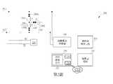
第1圖是本發明一實施例之電源管理系統100的示意圖。在第1圖中,可包含第一電源線PL1、第二電源線PL2、第一並聯保護器110A、第二並聯保護器110B、第三並聯保護器110C、第一電流感測器120A、第二電流感測器120B、第三電流感測器120C及處理器130。FIG. 1 is a schematic diagram of a
在有些實施例中,第一電源線PL1及第二電源線PL2可以共同傳輸交流電源以供電器設備所需。由於電器設備可能會設置在工業或戶外環境中,因此交流電源的供應也可能會受到外在環境影響而產生波動,甚至出現突波。為避免電器設備的操作受到干擾,電源管理系統100可以透過第一並聯保護器110A、第二並聯保護器110B及第三並聯保護器110C來提供突波洩流路徑,以避免第一電源線PL1及/或第二電源線PL2上產生的突波造成電器損害。此外,處理器130可耦接至第一電流感測器120A、第二電流感測器120B及第三電流感測器120C,並可根據第一電流感測器120A、第二電流感測器120B及第三電流感測器120C所感測到的電流來監控交流電源的波形。In some embodiments, the first power line PL1 and the second power line PL2 can jointly transmit AC power for the power supply device. Since electrical equipment may be set up in an industrial or outdoor environment, the supply of AC power may also be affected by the external environment and cause fluctuations or even surges. To avoid interference with the operation of electrical equipment, the
在第1圖中,第一並聯保護器110A可具有第一端及第二端,第一並聯保護器110A的第一端可耦接於第一電源線PL1。第二並聯保護器110B可具有第一端及第二端,第二並聯保護器110B的第一端可耦接於第一並聯保護器110A之第二端,而第二並聯保護器110B的第二端可耦接於第二電源線PL2。第三並聯保護器110C可具有第一端及第二端,第三並聯保護器110C的第一端可耦接於第一並聯保護器110A之第二端,而第三並聯保護器110C的第二端可耦接於接地端GND。In Figure 1, the first
第一電流感測器120A可以鄰近於第一並聯保護器110A設置,並可感測流經第一並聯保護器110A的第一電流I1。第二電流感測器120B可以鄰近於第二並聯保護器110B設置,並可感測流經第二並聯保護器110B的第二電流I2。第三電流感測器120C可以鄰近於第三並聯保護器110C設置,並可感測流經第三並聯保護器110C的第三電流I3。The first
在有些實施例中,第一電流感測器120A、第二電流感測器120B及第三電流感測器120C可以是霍爾電流感測器(Hall Sensor),因此可以利用電磁感應的原理,在與第一並聯保護器110A、第二並聯保護器110B及第三並聯保護器110C相隔離的狀態下,感應出流經第一並聯保護器110A、第二並聯保護器110B及第三並聯保護器110C的電流。如此一來,即使在突波產生時,第一電流感測器120A、第二電流感測器120B及第三電流感測器120C仍然可以正常運作。此外,霍爾電流感測器的反應速度快,因此處理器130也可以完整地記錄突波產生時的電流波形,有利於管理者對電源傳輸做進一步的改進及規劃。In some embodiments, the first
在有些實施例中,第一並聯保護器110A、第二並聯保護器110B及第三並聯保護器110C在交流電源正常的情況下會具有較高的阻抗,因此第一電流感測器120A、第二電流感測器120B及第三電流感測器120C並不會感應到明顯的電流。然而,當第一並聯保護器110A、第二並聯保護器110B及第三並聯保護器110C的端電壓過大時,例如當突波發生時,第一並聯保護器110A、第二並聯保護器110B及第三並聯保護器110C的阻抗就會變低,因此可以在第一電源線PL1及第二電源線PL2之間提供洩流路徑。第一並聯保護器110A、第二並聯保護器110B及第三並聯保護器110C可例如但不限於各包含暫態電壓抑制器(Transient Voltage Suppressor,TVS)、氣體放電管(Gas Discharge Tube,GDT)或壓敏電阻(Varistor)。In some embodiments, the first
此外,由於處理器130可以透過第一電流感測器120A、第二電流感測器120B及第三電流感測器120C來監測第一電流I1、第二電流I2及第三電流I3,因此可以藉以判斷出突波的洩流路徑。舉例來說,若處理器130監測到明顯的第一電流I1及第二電流I2,而並未監測到明顯的第三電流I3,就表示突波的洩流路徑主要會經過第一並聯保護器110A及第二並聯保護器110B,而較少經過第三並聯保護器110C。相對地,當處理器130監測到明顯的第三電流I3,通常表示突波的洩流路徑會通往接地端GND。In addition, since the
在有些實施例中,不同原因所產生的突波,可能會導致洩流路徑的不同。舉例來說,雷擊會在第一電源線PL1及第二電源線PL2上造成共模的突波,因此突波洩流路徑通常會自第一電源線PL1及第二電源線PL2經由第一並聯保護器110A、第二並聯保護器110及第三並聯保護器110C流至接地端。相對地,由馬達或其他裝置的抽載電流造成的突波則可能只會發生在第一電源線PL1或第二電源線PL2上,因此突波洩流路徑主要會經過串聯在第一電源線PL1及第二電源線PL2之間的第一並聯保護器110A及第二並聯保護器110B,而較少通過第三並聯保護器110C。因此,在有些實施例中,處理器130還可以根據突波洩流的路徑來判斷突波產生的原因。In some embodiments, surges generated by different reasons may cause different leakage paths. For example, a lightning strike will cause common-mode surges on the first power line PL1 and the second power line PL2. Therefore, the surge leakage path usually runs from the first power line PL1 and the second power line PL2 through the first parallel connection. The
在有些實施例中,處理器130可包含資料處理單元132。資料處理單元132可以記錄電流感測器120A、120B、120C所傳來的數據,並進行數據處理或分析。此外,在有些實例中處理器130還可包含有線傳輸模組134及/或無線傳輸模組136,有線傳輸模組134及無線傳輸模組136可將資料處理單元132所記錄的數據傳送到遠端監控系統CS1,使得管理者能夠在遠端做更複雜的數據分析。In some embodiments, the
在第1圖中,電源管理系統100還可包含隔離電源供應器140、穩壓器備源電路150及穩壓器電路160。隔離電源供應器140可耦接於第一電源線PL1及第二電源線PL2,並且可以將交流電源轉換為直流電源。穩壓器備源電路150可耦接於隔離電源供應器140,並且可以根據直流電源提供穩壓電源。穩壓器電路160可耦接於穩壓器備源電路150,並且可以根據穩壓電源提供處理器130所需之電壓。在有些實施例中,穩壓器備源電路150所提供的穩壓電源可例如包含12V的電壓源,而穩壓器電路160則可提供3.3V的電壓源,然而本發明並不以此為限。In Figure 1, the
在此實施例中,穩壓器備源電路150可以在電源管理系統100異常斷電後的一時段內,例如三秒內,持續提供穩壓電源,使得處理器130可以在電源管理系統100異常斷電後的該時段內,記錄電源管理系統100的電源數據,並透過有線傳輸模組134或無線傳輸模組與遠端監控系統CS1連線,而將其所記錄的電源數據傳送至遠端監控系統CS1,使得檢測人員可以在遠端得知系統異常的訊息,並做出即時的應對或在事後得知異常斷電時的狀況In this embodiment, the voltage
由於電源管理系統100可以利用第一電流感測器120A、第二電流感測器120B及第三電流感測器120C在與第一並聯保護器110A、第二並聯保護器110B及第三並聯保護器110C隔離的情況下,感測流經第一並聯保護器110A、第二並聯保護器110B及第三並聯保護器110C的電流,因此在突波發生時,處理器130可以即時且完整地記錄電流波形,並且可以判斷出突波洩流路徑,使得檢測人員可以根據電源管理系統100所提供的數據分析發生異常的原因。Since the
第2圖是本發明另一實施例之電源管理系統200的示意圖。電源管理系統200與電源管理系統100具有相似的結構,並可根據相似的原理操作。然而。電源管理系統200還可包含限流電阻R1及電壓感測器270。FIG. 2 is a schematic diagram of a
限流電阻R1具有第一端及第二端,限流電阻R1的第一端可耦接於第一電源線PL1,而限流電阻R1的第二端可耦接於第二電源線PL2。電壓感測器270可以透過感測電流的方式感測流經限流電阻R1的第四電流I4進而得到電壓。在有些實施例中,設計者可以根據電壓感測器270的規格來選擇限流電阻R1的阻值大小。舉例來說,若電壓感測器270主要是用於感測大小約25毫安培的電流,則設計者可以根據交流電源的大小選擇適當的限流電阻R1。The current limiting resistor R1 has a first end and a second end. The first end of the current limiting resistor R1 can be coupled to the first power line PL1, and the second end of the current limiting resistor R1 can be coupled to the second power line PL2. The
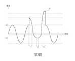
第3圖是本發明一實施例之第四電流I4的波形圖。由於第四電流I4的波形會與交流電源在第一電源線PL1上的電壓波形同步變化,因此處理器230中的資料處理單元232可以記錄第四電流I4的波形及對應時間以便檢測人員得知交流電源的波形。此外,在有些實施例中,當第四電流I4的數值超過預定範圍時,例如在時段T1中,第四電流I4的數值大於預定範圍的邊界值A1,而在時段T2中,第四電流I4的峰值數值小於預定範圍的邊界值A2,因此處理器230可將時段T1及T2中的異常紀錄下來,並可透過有線傳輸模組234或無線傳輸模組236向遠端監控系統CS1發出警告訊號。Fig. 3 is a waveform diagram of the fourth current I4 according to an embodiment of the present invention. Since the waveform of the fourth current I4 changes synchronously with the voltage waveform of the AC power on the first power line PL1, the
也就是說,電源管理系統200可以透過電壓感測器270對第一電源線PL1及第二電源線PL2上的交流電源做持續的監控。此外,在第3圖的時段T3中產生了突波,此時處理器230除了可以持續記錄第四電流I4的波形之外,還可以透過第一電流感測器120A、第二電流感測器120B及第三電流感測器120C來感測突波發生時,洩流路徑上的電流波形,藉以取得更多的數據以供檢測者分析突波發生的原因。In other words, the
綜上所述,本發明之實施例所提供的電源管理系統可以利用霍爾電流感測器感測流經並聯保護器上的電流,因此在突波發生時,處理器可以即時且完整地記錄電流波形,並且可以判斷出突波洩流路徑,以供檢測人員後續分析異常原因。此外,在未發生突波時,電源管理系統也可透過電流感測器持續監測交流電源的電壓波形變化,並在交流電源的電壓超過預定範圍時,發出警告訊號,以使檢測人員能夠即時反應。 以上所述僅為本發明之較佳實施例,凡依本發明申請專利範圍所做之均等變化與修飾,皆應屬本發明之涵蓋範圍。In summary, the power management system provided by the embodiment of the present invention can use the Hall current sensor to sense the current flowing through the parallel protector, so when a surge occurs, the processor can record it instantly and completely The current waveform can be used to determine the surge leakage path for the inspector to analyze the cause of the abnormality later. In addition, when there is no surge, the power management system can also continuously monitor the voltage waveform change of the AC power source through the current sensor, and issue a warning signal when the voltage of the AC power source exceeds a predetermined range, so that the inspector can react immediately . The above descriptions are only preferred embodiments of the present invention, and all equivalent changes and modifications made in accordance with the scope of the patent application of the present invention should fall within the scope of the present invention.
100、200:電源管理系統 110A、110B、110C:並聯保護器 120A、120B、120C:電流感測器 130、230:處理器 132、232:資料處理單元 134、234:有線傳輸模組 136、236:無線傳輸模組 270:電壓感測器 PL1、PL2:電源線 140:隔離電源供應器 150:穩壓器備源電路 160:穩壓器電路 CS1:遠端控制系統 GND:接地端 I1、I2、I3、I4:電流 R1:限流電阻 A1、A2:邊界值 T1、T2、T3:時段100, 200:
第1圖是本發明一實施例之電源管理系統的示意圖。 第2圖是本發明另一實施例之電源管理系統的示意圖。 第3圖是本發明一實施例之電流波形圖。Figure 1 is a schematic diagram of a power management system according to an embodiment of the present invention. Figure 2 is a schematic diagram of a power management system according to another embodiment of the present invention. Figure 3 is a current waveform diagram of an embodiment of the present invention.
100:電源管理系統100: Power Management System
110A、110B、110C:並聯保護器110A, 110B, 110C: Parallel protector
120A、120B、120C:電流感測器120A, 120B, 120C: current sensor
130:處理器130: processor
132:資料處理單元132: Data Processing Unit
134:有線傳輸模組134: Wired transmission module
136:無線傳輸模組136: wireless transmission module
PL1、PL2:電源線PL1, PL2: power cord
140:隔離電源供應器140: Isolated power supply
150:穩壓器備源電路150: Voltage stabilizer backup source circuit
160:穩壓器電路160: voltage regulator circuit
CS1:遠端控制系統CS1: Remote control system
GND:接地端GND: ground terminal
I1、I2、I3:電流I1, I2, I3: current
Claims (8)
Translated fromChinesePriority Applications (6)
| Application Number | Priority Date | Filing Date | Title |
|---|---|---|---|
| TW109143876ATWI729966B (en) | 2020-12-11 | 2020-12-11 | Power management system |
| CN202011568283.1ACN114624622A (en) | 2020-12-11 | 2020-12-25 | power management system |
| US17/327,804US11374398B1 (en) | 2020-12-11 | 2021-05-24 | Power management system |
| EP21176154.9AEP4012868A1 (en) | 2020-12-11 | 2021-05-27 | Power management system |
| KR1020210079947AKR102632978B1 (en) | 2020-12-11 | 2021-06-21 | Power management system |
| JP2021105284AJP7104836B2 (en) | 2020-12-11 | 2021-06-25 | Power management system |
Applications Claiming Priority (1)
| Application Number | Priority Date | Filing Date | Title |
|---|---|---|---|
| TW109143876ATWI729966B (en) | 2020-12-11 | 2020-12-11 | Power management system |
Publications (2)
| Publication Number | Publication Date |
|---|---|
| TWI729966Btrue TWI729966B (en) | 2021-06-01 |
| TW202224302A TW202224302A (en) | 2022-06-16 |
Family
ID=76159289
Family Applications (1)
| Application Number | Title | Priority Date | Filing Date |
|---|---|---|---|
| TW109143876ATWI729966B (en) | 2020-12-11 | 2020-12-11 | Power management system |
Country Status (6)
| Country | Link |
|---|---|
| US (1) | US11374398B1 (en) |
| EP (1) | EP4012868A1 (en) |
| JP (1) | JP7104836B2 (en) |
| KR (1) | KR102632978B1 (en) |
| CN (1) | CN114624622A (en) |
| TW (1) | TWI729966B (en) |
Citations (3)
| Publication number | Priority date | Publication date | Assignee | Title |
|---|---|---|---|---|
| US9618586B2 (en)* | 2013-02-12 | 2017-04-11 | Abb Schweiz Ag | Method and device for detection of a fault in a protected unit |
| US20170117699A1 (en)* | 2011-07-29 | 2017-04-27 | Leviton Manufacturing Company | Arc fault circuit interrupter |
| EP3407460B1 (en)* | 2016-02-05 | 2020-08-19 | Guangdong Oppo Mobile Telecommunications Corp., Ltd. | Terminal charging system, charging method, and power adapter |
Family Cites Families (21)
| Publication number | Priority date | Publication date | Assignee | Title |
|---|---|---|---|---|
| GB1354245A (en)* | 1972-05-18 | 1974-06-05 | Gni Energet I Im Gm Krzhizhano | Electrical power surge arrestors |
| KR100643313B1 (en)* | 2006-02-02 | 2006-11-13 | (주)국제첨단산업기술 | Intelligent uninterruptible lighting system of digital control method using communication connection of 1: N mode control line |
| US7933108B2 (en)* | 2007-12-18 | 2011-04-26 | Rockwell Automation Technologies, Inc. | Motor drive with low leakage surge protection |
| JP5220530B2 (en)* | 2008-09-19 | 2013-06-26 | 株式会社Nttファシリティーズ | Surge protection device |
| DE102009004673A1 (en) | 2009-01-12 | 2010-07-15 | Phoenix Contact Gmbh & Co. Kg | Snubber |
| GB0919699D0 (en)* | 2009-11-11 | 2009-12-30 | Kitchener Renato | Fault diagnostics, surge detection and failure prediction method |
| KR101332304B1 (en) | 2012-01-31 | 2013-11-22 | 주식회사 메가베스 | surge protecting system for energy storage apparatus and method therefor |
| US8995107B2 (en)* | 2012-10-01 | 2015-03-31 | Ceramate Technical Co., Ltd. | Modular lightning surge protection apparatus |
| KR101465401B1 (en)* | 2014-06-26 | 2014-12-05 | 삼현씨앤에스 주식회사 | Lifetime estimating device of surge protector and method thereof |
| JP6474230B2 (en) | 2014-10-31 | 2019-02-27 | 株式会社サンコーシヤ | Surge protection system |
| JP6218190B2 (en)* | 2015-08-31 | 2017-10-25 | 株式会社昭電 | Abnormality detection circuit for communication surge protection element |
| DE102015016232A1 (en)* | 2015-12-16 | 2017-06-22 | Wilo Se | Switchable overvoltage protection arrangement |
| CN106961098A (en)* | 2016-01-08 | 2017-07-18 | 西门子公司 | A kind of surge protection circuit and surge protection method |
| CZ29467U1 (en) | 2016-04-28 | 2016-05-23 | Saltek S.R.O. | Circuit arrangement of a device for monitoring, evaluating and sugnaling of overvoltage protection state |
| DE102016113267A1 (en)* | 2016-07-19 | 2018-01-25 | Epcos Ag | Device for protection against overvoltages and use of a device for protection against overvoltages |
| FR3058276B1 (en)* | 2016-11-03 | 2019-05-10 | Citel | DEVICE FOR PROTECTING TRANSIENT OVERVOLTAGES |
| JP2019032315A (en)* | 2017-08-04 | 2019-02-28 | 一般財団法人 関西電気保安協会 | Grounding factor determination method |
| CN109755931A (en)* | 2017-11-06 | 2019-05-14 | 东莞市阿甘半导体有限公司 | A kind of AC power surge protection device and electronic equipment |
| DE102019135206B4 (en)* | 2019-12-19 | 2022-01-27 | Karl Storz Se & Co. Kg | surge protector and power supply |
| CN111856127A (en) | 2020-07-30 | 2020-10-30 | 慈溪市万能电子有限公司 | A lightning protection monitoring system and lightning current monitoring method |
| CN111900705B (en)* | 2020-08-06 | 2022-11-18 | 深圳市凯冠智能科技有限公司 | Lightning stroke protection circuit, control method and equipment of PSE equipment |
- 2020
- 2020-12-11TWTW109143876Apatent/TWI729966B/enactive
- 2020-12-25CNCN202011568283.1Apatent/CN114624622A/enactivePending
- 2021
- 2021-05-24USUS17/327,804patent/US11374398B1/enactiveActive
- 2021-05-27EPEP21176154.9Apatent/EP4012868A1/enactivePending
- 2021-06-21KRKR1020210079947Apatent/KR102632978B1/enactiveActive
- 2021-06-25JPJP2021105284Apatent/JP7104836B2/enactiveActive
Patent Citations (4)
| Publication number | Priority date | Publication date | Assignee | Title |
|---|---|---|---|---|
| US20170117699A1 (en)* | 2011-07-29 | 2017-04-27 | Leviton Manufacturing Company | Arc fault circuit interrupter |
| US20190356127A1 (en)* | 2011-07-29 | 2019-11-21 | Leviton Manufacturing Company, Inc. | Arc fault circuit interrupter |
| US9618586B2 (en)* | 2013-02-12 | 2017-04-11 | Abb Schweiz Ag | Method and device for detection of a fault in a protected unit |
| EP3407460B1 (en)* | 2016-02-05 | 2020-08-19 | Guangdong Oppo Mobile Telecommunications Corp., Ltd. | Terminal charging system, charging method, and power adapter |
Also Published As
| Publication number | Publication date |
|---|---|
| KR102632978B1 (en) | 2024-02-01 |
| TW202224302A (en) | 2022-06-16 |
| JP7104836B2 (en) | 2022-07-21 |
| KR20220083555A (en) | 2022-06-20 |
| US11374398B1 (en) | 2022-06-28 |
| JP2022093246A (en) | 2022-06-23 |
| EP4012868A1 (en) | 2022-06-15 |
| CN114624622A (en) | 2022-06-14 |
| US20220190593A1 (en) | 2022-06-16 |
Similar Documents
| Publication | Publication Date | Title |
|---|---|---|
| CN102714408B (en) | Circuit with surge protection monitoring | |
| US9118175B2 (en) | Overvoltage protector | |
| US7453368B2 (en) | Surge protector life cycle monitor system and method | |
| US10690709B2 (en) | System for monitoring resistance and current in ground line | |
| CN208140817U (en) | A kind of arrester on-line monitoring system | |
| CN105353234B (en) | A kind of SPD on-line monitorings prior-warning device | |
| CN101071521A (en) | Method and device for monitoring detector line of fire detection system for faults | |
| KR101163963B1 (en) | Appratus for protecting surge of monitoring data | |
| CN103650277B (en) | Monitoring device, photovoltaic system, and operating method for a power grid of an insulating structure for a photovoltaic system | |
| KR101027038B1 (en) | Communication system for surge protector | |
| CN108181501B (en) | Current signal acquisition circuit with protective action | |
| CN102074947A (en) | Intelligent surge protection device (SPD) | |
| KR20220039039A (en) | Apparatus for detecting surge and leakage current, and current detecting system | |
| CN110780106A (en) | A kind of surge protector monitoring method and device | |
| CN109787573B (en) | Input circuit for failsafe reading of analog input signals | |
| TWI729966B (en) | Power management system | |
| US20050270164A1 (en) | Electrical protection device & method for a communication circuit | |
| KR102215950B1 (en) | Voltage-limiter monitoring | |
| KR20190080221A (en) | Short circuit breaker with preventing malfunction and false notification by leakage current | |
| JP5348695B2 (en) | Overvoltage protection element failure detection circuit and subscriber circuit | |
| CN115494330A (en) | Method for estimating residual life of surge protector on line, surge protector and electronic equipment | |
| CN113075482A (en) | Electric power instrument | |
| CN206725680U (en) | A kind of monitoring system of arrester | |
| KR100858356B1 (en) | Surge Protection Device | |
| Finis et al. | Advanced Monitoring, Diagnostics, Remote Indication and Testing of SPDs Connected to Telecommunications and Signalling Networks |