TWI728524B - Battery assembly - Google Patents
Battery assemblyDownload PDFInfo
- Publication number
- TWI728524B TWI728524BTW108138493ATW108138493ATWI728524BTW I728524 BTWI728524 BTW I728524BTW 108138493 ATW108138493 ATW 108138493ATW 108138493 ATW108138493 ATW 108138493ATW I728524 BTWI728524 BTW I728524B
- Authority
- TW
- Taiwan
- Prior art keywords
- battery
- engaging portion
- battery unit
- locking member
- assembly according
- Prior art date
Links
Images


Classifications
- H—ELECTRICITY
- H01—ELECTRIC ELEMENTS
- H01M—PROCESSES OR MEANS, e.g. BATTERIES, FOR THE DIRECT CONVERSION OF CHEMICAL ENERGY INTO ELECTRICAL ENERGY
- H01M50/00—Constructional details or processes of manufacture of the non-active parts of electrochemical cells other than fuel cells, e.g. hybrid cells
- H01M50/20—Mountings; Secondary casings or frames; Racks, modules or packs; Suspension devices; Shock absorbers; Transport or carrying devices; Holders
- H01M50/262—Mountings; Secondary casings or frames; Racks, modules or packs; Suspension devices; Shock absorbers; Transport or carrying devices; Holders with fastening means, e.g. locks
- B—PERFORMING OPERATIONS; TRANSPORTING
- B62—LAND VEHICLES FOR TRAVELLING OTHERWISE THAN ON RAILS
- B62H—CYCLE STANDS; SUPPORTS OR HOLDERS FOR PARKING OR STORING CYCLES; APPLIANCES PREVENTING OR INDICATING UNAUTHORIZED USE OR THEFT OF CYCLES; LOCKS INTEGRAL WITH CYCLES; DEVICES FOR LEARNING TO RIDE CYCLES
- B62H5/00—Appliances preventing or indicating unauthorised use or theft of cycles; Locks integral with cycles
- B62H5/001—Preventing theft of parts or accessories used on cycles, e.g. lamp, dynamo
- B—PERFORMING OPERATIONS; TRANSPORTING
- B62—LAND VEHICLES FOR TRAVELLING OTHERWISE THAN ON RAILS
- B62J—CYCLE SADDLES OR SEATS; AUXILIARY DEVICES OR ACCESSORIES SPECIALLY ADAPTED TO CYCLES AND NOT OTHERWISE PROVIDED FOR, e.g. ARTICLE CARRIERS OR CYCLE PROTECTORS
- B62J43/00—Arrangements of batteries
- B62J43/10—Arrangements of batteries for propulsion
- B62J43/13—Arrangements of batteries for propulsion on rider-propelled cycles with additional electric propulsion
- B—PERFORMING OPERATIONS; TRANSPORTING
- B62—LAND VEHICLES FOR TRAVELLING OTHERWISE THAN ON RAILS
- B62J—CYCLE SADDLES OR SEATS; AUXILIARY DEVICES OR ACCESSORIES SPECIALLY ADAPTED TO CYCLES AND NOT OTHERWISE PROVIDED FOR, e.g. ARTICLE CARRIERS OR CYCLE PROTECTORS
- B62J43/00—Arrangements of batteries
- B62J43/20—Arrangements of batteries characterised by the mounting
- B62J43/23—Arrangements of batteries characterised by the mounting dismounted when charging
- B—PERFORMING OPERATIONS; TRANSPORTING
- B62—LAND VEHICLES FOR TRAVELLING OTHERWISE THAN ON RAILS
- B62J—CYCLE SADDLES OR SEATS; AUXILIARY DEVICES OR ACCESSORIES SPECIALLY ADAPTED TO CYCLES AND NOT OTHERWISE PROVIDED FOR, e.g. ARTICLE CARRIERS OR CYCLE PROTECTORS
- B62J43/00—Arrangements of batteries
- B62J43/20—Arrangements of batteries characterised by the mounting
- B62J43/28—Arrangements of batteries characterised by the mounting hidden within the cycle frame
- B—PERFORMING OPERATIONS; TRANSPORTING
- B62—LAND VEHICLES FOR TRAVELLING OTHERWISE THAN ON RAILS
- B62M—RIDER PROPULSION OF WHEELED VEHICLES OR SLEDGES; POWERED PROPULSION OF SLEDGES OR SINGLE-TRACK CYCLES; TRANSMISSIONS SPECIALLY ADAPTED FOR SUCH VEHICLES
- B62M6/00—Rider propulsion of wheeled vehicles with additional source of power, e.g. combustion engine or electric motor
- B62M6/80—Accessories, e.g. power sources; Arrangements thereof
- B62M6/90—Batteries
- H—ELECTRICITY
- H01—ELECTRIC ELEMENTS
- H01M—PROCESSES OR MEANS, e.g. BATTERIES, FOR THE DIRECT CONVERSION OF CHEMICAL ENERGY INTO ELECTRICAL ENERGY
- H01M50/00—Constructional details or processes of manufacture of the non-active parts of electrochemical cells other than fuel cells, e.g. hybrid cells
- H01M50/20—Mountings; Secondary casings or frames; Racks, modules or packs; Suspension devices; Shock absorbers; Transport or carrying devices; Holders
- H01M50/244—Secondary casings; Racks; Suspension devices; Carrying devices; Holders characterised by their mounting method
- H—ELECTRICITY
- H01—ELECTRIC ELEMENTS
- H01M—PROCESSES OR MEANS, e.g. BATTERIES, FOR THE DIRECT CONVERSION OF CHEMICAL ENERGY INTO ELECTRICAL ENERGY
- H01M50/00—Constructional details or processes of manufacture of the non-active parts of electrochemical cells other than fuel cells, e.g. hybrid cells
- H01M50/20—Mountings; Secondary casings or frames; Racks, modules or packs; Suspension devices; Shock absorbers; Transport or carrying devices; Holders
- H01M50/249—Mountings; Secondary casings or frames; Racks, modules or packs; Suspension devices; Shock absorbers; Transport or carrying devices; Holders specially adapted for aircraft or vehicles, e.g. cars or trains
- H—ELECTRICITY
- H01—ELECTRIC ELEMENTS
- H01M—PROCESSES OR MEANS, e.g. BATTERIES, FOR THE DIRECT CONVERSION OF CHEMICAL ENERGY INTO ELECTRICAL ENERGY
- H01M2220/00—Batteries for particular applications
- H01M2220/20—Batteries in motive systems, e.g. vehicle, ship, plane
- Y—GENERAL TAGGING OF NEW TECHNOLOGICAL DEVELOPMENTS; GENERAL TAGGING OF CROSS-SECTIONAL TECHNOLOGIES SPANNING OVER SEVERAL SECTIONS OF THE IPC; TECHNICAL SUBJECTS COVERED BY FORMER USPC CROSS-REFERENCE ART COLLECTIONS [XRACs] AND DIGESTS
- Y02—TECHNOLOGIES OR APPLICATIONS FOR MITIGATION OR ADAPTATION AGAINST CLIMATE CHANGE
- Y02E—REDUCTION OF GREENHOUSE GAS [GHG] EMISSIONS, RELATED TO ENERGY GENERATION, TRANSMISSION OR DISTRIBUTION
- Y02E60/00—Enabling technologies; Technologies with a potential or indirect contribution to GHG emissions mitigation
- Y02E60/10—Energy storage using batteries
Landscapes
- Engineering & Computer Science (AREA)
- Chemical & Material Sciences (AREA)
- Mechanical Engineering (AREA)
- Chemical Kinetics & Catalysis (AREA)
- Electrochemistry (AREA)
- General Chemical & Material Sciences (AREA)
- Combustion & Propulsion (AREA)
- Transportation (AREA)
- Aviation & Aerospace Engineering (AREA)
- Battery Mounting, Suspending (AREA)
Abstract
Description
Translated fromChinese本發明一般係關於一種電池組件,具體而言,本發明係關於一種具有兩段式卡合機制的電池組件。The present invention generally relates to a battery assembly, and specifically, the present invention relates to a battery assembly with a two-stage clamping mechanism.
一般電動自行車係利用電池作為電動馬達的動力來源,而電池通常附掛在自行車的車架上。為了避免電池受震脫離車架,通常會藉由鎖定機制加強電池的固定。然而,當使用者拆卸電池時,通常需要用一隻手扶住電池,再用另一隻手解除鎖定,以避免解除鎖定後電池直接自車架掉落,造成電池損傷及操作上的不便。Generally, electric bicycles use batteries as the power source of electric motors, and the batteries are usually attached to the frame of the bicycle. In order to prevent the battery from being shaken off the frame, a locking mechanism is usually used to strengthen the fixing of the battery. However, when the user disassembles the battery, he usually needs to hold the battery with one hand, and then unlock the lock with the other hand to prevent the battery from falling directly from the frame after the lock is unlocked, causing battery damage and inconvenience in operation.
本發明之一目的在於提供一種電池組件,其具有兩段式的卡合機制,以避免拆卸電池單元時,電池單元直接與電池固定座脫離。An object of the present invention is to provide a battery assembly with a two-stage clamping mechanism to prevent the battery unit from being directly separated from the battery holder when the battery unit is removed.
於一實施例,本發明提供一種電池組件,其包含電池單元及電池固定座,其中電池單元可拆卸地設置於電池固定座;電池單元包含電池、第一卡合部及第二卡合部,第一卡合部及第二卡合部設置於電池的端部,且第二卡合部可相對於端部活動;電池固定座包含卡止件,卡止件選擇性與第一卡合部或第二卡合部卡合,以將電池單元定位於第一位置或第二位置;當卡止件與第一卡合部沿解鎖方向相對移動解除卡合時,電池單元沿脫離方向自第一位置移動至卡止件與第二卡合部卡合的第二位置,並容許第二卡合部相對於端部活動以解除與卡止件的卡合,使得電池單元沿脫離方向再次移動以脫離電池固定座。In one embodiment, the present invention provides a battery assembly, which includes a battery unit and a battery holder, wherein the battery unit is detachably disposed on the battery holder; the battery unit includes a battery, a first engaging portion, and a second engaging portion, The first engaging portion and the second engaging portion are arranged at the end of the battery, and the second engaging portion is movable relative to the end; the battery fixing seat includes a locking member, and the locking member is selectively connected to the first engaging portion Or the second engaging portion is engaged to position the battery unit at the first position or the second position; when the locking member and the first engaging portion move relative to each other in the unlocking direction to release the engagement, the battery unit moves from the first position in the disengaging direction. A position is moved to the second position where the locking member is engaged with the second engaging portion, and the second engaging portion is allowed to move relative to the end to release the engagement with the locking member, so that the battery unit moves again in the disengagement direction To detach the battery holder.
於一實施例,本發明的電池組件更包含鎖具,其中鎖具設置於電池固定座以耦接卡止件,鎖具於鎖定狀態時,限制卡止件與第一卡合部相對移動而保持卡合,且鎖具於解鎖狀態時,帶動卡止件沿解鎖方向移動,以解除卡止件與第一卡合部的卡合。In one embodiment, the battery assembly of the present invention further includes a lock device, wherein the lock device is disposed on the battery fixing base to be coupled to the locking member. When the lock device is in a locked state, the locking member and the first engaging portion are restricted from moving relative to each other to maintain engagement , And when the lock is in the unlocked state, the locking member is driven to move in the unlocking direction to release the engagement between the locking member and the first engaging portion.
於一實施例,電池單元包含活動板,第一卡合部及第二卡合部沿脫離方向間隔設置於活動板,且電池單元定位於第一位置時,第二卡合部於脫離方向的投影至少部分在第一卡合部的外側。In one embodiment, the battery unit includes a movable plate, and the first engaging portion and the second engaging portion are arranged on the movable plate at intervals along the disengagement direction, and when the battery unit is positioned at the first position, the second engagement portion is in the disengagement direction. The projection is at least partly outside the first engaging portion.
於一實施例,活動板可轉動地設置於電池的端部且更具有操作部,第一卡合部設置於第二卡合部及操作部之間,操作部係受力以驅使活動板轉動,而帶動第二卡合部遠離卡止件以解除卡合。In one embodiment, the movable plate is rotatably arranged at the end of the battery and further has an operating part, the first engaging part is arranged between the second engaging part and the operating part, and the operating part is forced to drive the movable plate to rotate , And drive the second engaging portion away from the locking member to release the engagement.
於一實施例,活動板可轉動地設置於電池的端部,且電池單元更包含操作部,操作部可轉動地耦接活動板於鄰近第一卡合部的一端,操作部係供受力以驅使活動板轉動,進而解除第二卡合部及卡止件的卡合。In one embodiment, the movable plate is rotatably disposed at the end of the battery, and the battery unit further includes an operating part. The operating part is rotatably coupled to the movable plate at an end adjacent to the first engaging part, and the operating part is for receiving force. The movable plate is driven to rotate, thereby releasing the engagement between the second engagement portion and the engagement member.
於一實施例,電池單元更包含作用件,其中作用件可活動地設置於電池的側邊,作用件受外力推抵操作部以帶動第二卡合部遠離卡止件而解除卡合,外力的施加方向垂直於解鎖方向及/或脫離方向。In one embodiment, the battery unit further includes an acting member, wherein the acting member is movably disposed on the side of the battery, and the acting member is pushed against the operating portion by an external force to drive the second engaging portion away from the locking member to release the engagement. The application direction of the external force is perpendicular to the unlocking direction and/or the disengaging direction.
於一實施例,作用件受外力係可變形或可轉動以推抵操作部。In one embodiment, the acting member can be deformed or rotated by an external force to push against the operating portion.
於一實施例,第一卡合部及第二卡合部分別設置於電池的端部,以使第二卡合部可相對於第一卡合部移動;電池單元定位於第一位置時,第二卡合部於脫離方向的投影至少部分在第一卡合部的外側,且當電池單元定位於第二位置時,容許第二卡合部相對於第一卡合部向電池內側移動,以解除與卡止件的卡合。In one embodiment, the first engaging portion and the second engaging portion are respectively disposed at the ends of the battery, so that the second engaging portion can move relative to the first engaging portion; when the battery unit is positioned at the first position, The projection of the second engaging portion in the disengagement direction is at least partially outside the first engaging portion, and when the battery unit is positioned at the second position, the second engaging portion is allowed to move to the inside of the battery relative to the first engaging portion, To release the engagement with the locking member.
於一實施例,第一卡合部及第二卡合部分別設置於電池的端部,以使第二卡合部可相對於第一卡合部移動;電池單元定位於第一位置時,第二卡合部於脫離方向的投影至少部分在第一卡合部的外側,且當該電池單元定位於第二位置時,容許第二卡合部相對於第一卡合部向電池側向移動,以使第二卡合部與卡止件錯位而解除卡合。In one embodiment, the first engaging portion and the second engaging portion are respectively disposed at the ends of the battery, so that the second engaging portion can move relative to the first engaging portion; when the battery unit is positioned at the first position, The projection of the second engaging portion in the disengagement direction is at least partially outside the first engaging portion, and when the battery unit is positioned at the second position, the second engaging portion is allowed to face the battery side relative to the first engaging portion Move so that the second engaging portion and the locking member are misaligned to release the engagement.
於一實施例,第二卡合部側向移動的方向垂直於脫離方向及解鎖方向。In one embodiment, the direction in which the second engaging portion moves laterally is perpendicular to the disengaging direction and the unlocking direction.
於一實施例,電池單元更包含操作部,操作部對應第二卡合部設置,操作部係受力以驅使第二卡合部相對於第一卡合部向電池側向移動,使第二卡合部於脫離方向的投影與卡止件不重合。In one embodiment, the battery unit further includes an operating portion, the operating portion is provided corresponding to the second engaging portion, the operating portion is forced to drive the second engaging portion relative to the first engaging portion to move laterally to the battery, so that the second The projection of the engagement part in the disengagement direction does not coincide with the engagement member.
於一實施例,本發明的電池組件更包含鎖具,其中鎖具設置於電池單元以耦接第一卡合部;鎖具於鎖定狀態時,限制卡止件與第一卡合部相對移動而維持卡合,且鎖具於解鎖狀態時,帶動第一卡合部沿解鎖方向移動,以解除卡止件與第一卡合部的卡合。In one embodiment, the battery assembly of the present invention further includes a lock, wherein the lock is disposed on the battery unit to be coupled to the first engaging portion; when the lock is in the locked state, the relative movement of the locking member and the first engaging portion is restricted to maintain the lock. When the lock is in the unlocked state, the first engaging portion is driven to move in the unlocking direction to release the engagement between the locking member and the first engaging portion.
於一實施例,當電池單元定位於第二位置時,容許第二卡合部相對於第一卡合部向電池內側移動,以解除與卡止件的卡合。In one embodiment, when the battery unit is positioned at the second position, the second engaging portion is allowed to move toward the inner side of the battery relative to the first engaging portion to release the engagement with the locking member.
於一實施例,電池單元更包含彈性件,彈性件設置於活動板及電池的端部之間,彈性件提供回復力以使第二卡合部於脫離方向的投影保持至少部分在第一卡合部的外側。In one embodiment, the battery unit further includes an elastic member, the elastic member is disposed between the movable plate and the end of the battery, and the elastic member provides a restoring force to keep the projection of the second engaging portion in the disengaging direction at least partially in the first card The outside of the joint.
於一實施例,卡止件具有卡止部及擋止面,卡止件藉由卡止部選擇性與第一卡合部或第二卡合部卡合,以定位電池單元於第一位置或第二位置,且當電池單元定位於第一位置時,擋止面與第二卡合部對應。In one embodiment, the locking member has a locking portion and a stopping surface, and the locking portion is selectively engaged with the first locking portion or the second locking portion by the locking portion to position the battery unit in the first position Or the second position, and when the battery unit is positioned at the first position, the blocking surface corresponds to the second engaging portion.
於一實施例,電池固定座更包含基座,卡止件設置於基座,基座具有擋止面;當電池單元定位於第一位置時,擋止面與第二卡合部對應。In one embodiment, the battery holder further includes a base, the locking member is disposed on the base, and the base has a stopping surface; when the battery unit is positioned at the first position, the stopping surface corresponds to the second engaging portion.
於一實施例,電池固定座更包含基座,卡止件設置於基座,且電池的端部具有導槽,基座沿導槽相對移動,以導引電池單元相對於電池固定座移動。In one embodiment, the battery holder further includes a base, the locking member is disposed on the base, and the end of the battery has a guide groove, and the base moves relatively along the guide groove to guide the battery unit to move relative to the battery holder.
於一實施例,電池固定座更包含基座,卡止件設置於基座,電池單元於端部具有凹陷部,基座的外壁沿凹陷部的側壁相對移動以導引電池單元相對於電池固定座移動。In one embodiment, the battery fixing seat further includes a base, the locking member is disposed on the base, the battery unit has a recess at the end, and the outer wall of the base moves relative to the side wall of the recess to guide the battery unit to be fixed relative to the battery Block move.
於一實施例,電池固定座更包含基座,卡止件設置於基座,基座於面對電池單元的一側具有導引面,電池單元於端部具有導引壁,導引壁沿導引面相對移動以導引電池單元相對於電池固定座移動。In one embodiment, the battery holder further includes a base, the locking member is disposed on the base, the base has a guiding surface on the side facing the battery unit, the battery unit has a guiding wall at the end, and the guiding wall is The guiding surface moves relatively to guide the battery unit to move relative to the battery fixing seat.
於一實施例,解鎖方向實質垂直於脫離方向。In one embodiment, the unlocking direction is substantially perpendicular to the disengaging direction.
相較於習知技術,本發明的電池組件藉由電池單元與電池固定座的兩段式卡合機制,不僅加強電池單元與電池固定座的鎖定效果,更於第一段卡合解除後,電池單元與電池固定座仍可保持卡合,以提供使用者充裕的時間進行第二段卡合的解除,有效避免電池單元直接掉落以降低電池單元的損傷,並增進操作上的便利性。Compared with the prior art, the battery assembly of the present invention not only enhances the locking effect of the battery unit and the battery holder through the two-stage engagement mechanism of the battery unit and the battery holder, but also after the first stage of engagement is released, The battery unit and the battery holder can still remain engaged to provide the user with ample time to release the second stage of engagement, which effectively prevents the battery unit from falling directly to reduce the damage of the battery unit and enhance the convenience of operation.
本發明提供一種電池組件,其可應用於電動自行車,但不以此為限。本發明的電池組件可應用於任何需要兩段式拆卸操作的裝置,以提供安全、便利的方式拆卸電池組件。於後參考圖式,詳細說明本發明實施例之電池組件各元件之結構及操作。The present invention provides a battery assembly, which can be applied to electric bicycles, but is not limited to this. The battery assembly of the present invention can be applied to any device that requires a two-stage disassembly operation to provide a safe and convenient way to disassemble the battery assembly. In the following, referring to the drawings, the structure and operation of each component of the battery assembly of the embodiment of the present invention will be described in detail.
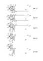
圖1為本發明一實施例之電池組件之示意圖。如圖1所示,電池組件1包含電池單元10及電池固定座20。電池單元10可拆卸地設置於電池固定座20。電池單元10包含電池110、第一卡合部122及第二卡合部124。第一卡合部122及第二卡合部124設置於電池110的端部112,且第二卡合部124可相對於端部112活動。電池固定座20包含卡止件210。卡止件210可選擇性與第一卡合部122或第二卡合部124卡合,以定位電池單元10於第一位置或第二位置。當卡止件210與第一卡合部122沿解鎖方向D1(標示於圖3)相對移動解除卡合時,電池單元10沿脫離方向D2(標示於圖2)自第一位置移動至卡止件210與第二卡合部124卡合的第二位置,並容許第二卡合部124相對於端部112活動以解除與卡止件210的卡合,使得電池單元10脫離電池固定座20。FIG. 1 is a schematic diagram of a battery assembly according to an embodiment of the invention. As shown in FIG. 1, the
請同時參考圖1及圖2,其中圖2為圖1之電池單元的局部放大分解示意圖。具體而言,電池110於長軸方向具有相對的兩端部112及114,其中端部112鄰近電池固定座20,且端部114遠離電池固定座20。電池單元10包含活動板120,活動板120可轉動地設置於電池110的端部112,且第一卡合部122及第二卡合部124沿脫離方向D2間隔設置於活動板120。於一實施例,電池110於端部112設置有電池蓋130,且電池蓋130與活動板120之間可具有樞接機構(例如軸孔及樞軸),以使得活動板120與電池蓋130可轉動地連接而可相對於端部112轉動。舉例而言,電池蓋130具有軸孔132,活動板120具有相應的軸部128,且軸部128插入軸孔132,以使得活動板120可相對於電池蓋130(或端部112)轉動。於一實施例,軸部128可與活動板120一體成形,而為自活動板120側向延伸而出的凸柱,但不以此為限。於另一實施例,軸部128與活動板120可為個別的部件,例如活動板120可具有對應軸孔132的通孔,軸部128可為貫穿通孔且兩端突出於活動板120的軸桿。Please refer to FIG. 1 and FIG. 2 at the same time. FIG. 2 is a partial enlarged and exploded schematic diagram of the battery unit of FIG. 1. Specifically, the
活動板120可更具有操作部126,且第一卡合部122設置於第二卡合部124及操作部126之間。具體而言,第二卡合部124、第一卡合部122及操作部126沿電池單元10自電池固定座20的脫離方向D2依序設置,亦即第二卡合部124、第一卡合部122及操作部126分別位於脫離方向D2的上游、中游及下游。換句話說,當脫離方向D2為向下脫離時,第二卡合部124、第一卡合部122及操作部126依序由上往下設置。操作部126係受力驅使該活動板轉動,例如供使用者推壓,以驅使活動板120轉動,且第二卡合部124相應移動而遠離卡止件210。於一實施例,第一卡合部122及第二卡合部124為卡勾形式,且在脫離方向D2上,第二卡合部124的卡勾頂點較佳位於第一卡合部122外側。換句話說,在脫離方向D2上,第二卡合部124的投影至少部分在第一卡合部122的外側(或至少部不與第一卡合部122重疊),亦即第二卡合部124比第一卡合部122更朝電池固定座20突出。於一實施例,操作部126為自第一卡合部122朝遠離第二卡合部124的方向延伸的板體或桿體,且操作部126較佳朝電池固定座10的方向傾斜。The
再者,電池單元10可更包含彈性件140。彈性件140設置於活動板120及電池110的端部112之間。彈性件140提供回復力,以使第二卡合部124於脫離方向D2的投影保持至少部分在第一卡合部122的外側。彈性件140可為壓縮或拉伸彈簧,且可對應第二卡合部124或操作部126設置,以提供對應的回復力使第二卡合部124保持突出於第一卡合部122。於一實施例,如圖2所示,彈性件140對應第二卡合部124設置於電池110的端部112,且彈性件140提供回復力以朝電池固定座20的方向推抵第二卡合部124。舉例而言,彈性件140設置於電池蓋130與活動板120之間,且彈性件140的位置對應於第二卡合部124。彈性件140可實施為壓縮彈簧,且其兩端分別耦接電池蓋130與活動板120。於一實施例,如圖2A所示,活動板120在相對於第二卡合部124的一側,即面向電池蓋130的一側,開設有定位孔129,以供定位彈性件140。亦即,彈性件140可部分容置於定位孔129,而定位於電池蓋130與活動板120之間,但不此為限。於另一實施例(未繪示),活動板120或電池蓋130可具有定位柱,彈性件140可套設於定位柱而被定位。如圖5B所示,於另一實施例,彈性件140對應操作部126設置於電池110的端部112,且彈性件140可實施為拉伸彈簧,以提供回復力將操作部126朝電池固定座20的方向拉向電池110的端部112,而讓第二卡合部124保持突出於第一卡合部122或維持在卡合狀態。Furthermore, the
請同時參考圖1及圖3,其中圖3為圖1之電池固定座的分解示意圖。於一實施例,電池固定座20可更包含鎖具220、基座230及彈性件240。鎖具220設置於電池固定座20以耦接卡止件210。具體而言,鎖具220及卡止件210分別設置於基座230的相對兩側,且彈性件240設置於鎖具220及卡止件210之間。因應鎖具220的鎖定及解鎖,可限制或容許卡止件210沿解鎖方向D1移動。舉例而言,鎖具220於鎖定狀態時,限制卡止件210與第一卡合部122沿解鎖方向D1相對移動而保持卡合;鎖具220於解鎖狀態時,帶動卡止件210沿解鎖方向D1移動,以解除卡止件210與第一卡合部122的卡合。Please refer to FIG. 1 and FIG. 3 at the same time. FIG. 3 is an exploded view of the battery holder of FIG. 1. In one embodiment, the
卡止件210具有卡止部212,卡止部212朝外突出,即朝電池單元10的方向突出。卡止部212可為具有對應第一卡合部122及第二卡合部124的形狀的卡勾形式,以與第一卡合部122或第二卡合部124卡合。卡止件210更具有耦接孔214,用以與鎖具220耦接。於一實施例,耦接孔214具有相互連通的第一孔部214a及第二孔部214b,且第一孔部214a的孔徑大於第二孔部214b的孔徑,以形成葫蘆形耦接孔214。The locking
鎖具220包含鎖本體222及驅動軸224。驅動軸224連接鎖本體222,且對應於鎖本體222的鎖定及解鎖相對於鎖本體222伸長或回縮,即沿解鎖方向D1伸長或回縮。舉例而言,鎖本體222可為鑰匙鎖或號碼鎖,並藉由鑰匙或密碼設定而處於鎖定狀態或解鎖狀態。當鎖本體222處於鎖定狀態時,驅動軸224相對於鎖本體222為伸長狀態。當鎖本體222處於解鎖狀態時,驅動軸224相對於鎖本體222為回縮狀態。亦即,驅動軸224為伸長狀態時相對於鎖本體222伸出的長度大於驅動軸224為回縮狀態時相對於鎖本體222伸出的長度。驅動軸224沿長軸方向包含頸部段226及頭部段228,且頸部段226垂直於長軸方向(或伸縮方向)的寬度(或徑向直徑)小於頭部段228。亦即,頸部段226相對於頭部段228內縮。The
基座230較佳為中空殼體形式,以容許卡止件210在基座230中相對於基座230移動。於一實施例,基座230包含第一側板232、座體234及第二側板236。座體234為內部具有容置空間2342的框體,且第一側板232及第二側板236相對於容置空間2342分別設置於座體234的相對兩側,以構成內部具有容置空間2342的殼體。第一側板232及第二側板236可藉由鎖固、卡合、黏著、焊接等方式與座體234連接,但不以此為限。於另一實施例,第一側板232及/或第二側板236可與座體234一體成形而形成內部具有容置空間2342的殼體。第一側板232鄰近鎖具220,而第二側板236鄰近卡止件210。第一側板232具有通孔2322,且第二側板236具有開口2364,通孔2322及開口2364與容置空間2342連通。通孔2322的尺寸對應驅動軸224,以容許驅動軸224通過,且開口2364的尺寸對應卡止件210,以容許卡止部212伸出。The
鎖具220設置於第一側板232的外側,且驅動軸224穿過通孔2322及容置空間2342。彈性元件240設置於第一側板232及卡止件212之間,並套設於驅動軸224。第一孔部214a的孔徑對應驅動軸224的頭部段228,且第二孔部214b的孔徑對應頸部段226,以容許驅動軸224自第一孔部214a通過耦接孔214,使得頭部段228位於卡止件210鄰近第二側板236的一側,且頸部段226位於耦接孔214的第一孔部214a中。藉此,組裝時,可朝第二孔部214b移動驅動軸224,以使頸部段226與第二孔部214b卡合,使得驅動軸224穩固地耦接卡止件210而形成連動機構,且卡止部212裸露於開口2364。The
請參考圖4A及圖4B,圖4A及圖4B分別為電池固定座將電池單元定位於第一位置及第二位置的剖面示意圖。如圖4A所示,當卡止件210與第一卡合部122卡合時,電池固定座20將電池單元10定位於第一位置。第一位置為電池單元10與電池固定座20結合且被鎖定的位置。舉例而言,在第一位置時,鎖具220可進行鎖定或解鎖的操作。當鎖具220處於鎖定狀態時,驅動軸224為伸長狀態且無法相對於鎖本體222移動,使得卡止件210與第一卡合部122無法沿解鎖方向D1相對移動保持卡合狀態,而將電池單元10鎖定於電池固定座20。於此實施例,基座230可具有擋止面2362。當電池單元10定位於第一位置時,擋止面2362與第二卡合部124對應,可更進一步限制活動板120的移動,以強化卡止件210與第一卡合部122的卡合。Please refer to FIGS. 4A and 4B. FIGS. 4A and 4B are schematic cross-sectional views of the battery holder positioning the battery unit at the first position and the second position, respectively. As shown in FIG. 4A, when the locking
如圖4B所示,當鎖具220由鎖定狀態變成解鎖狀態時,驅動軸224朝鎖本體222移動(即回縮),以帶動卡止件210沿解鎖方向D1移動遠離第一卡合部122而解除卡合狀態,電池單元10沿脫離方向D2自第一位置移動至卡止件210與第二卡合部124卡合的第二位置。舉例而言,當卡止件210與第一卡合部122解除卡合時,電池單元10可藉由重力相對於電池固定座20向下移動,而藉由第二卡合部與卡止件210卡合定位於第二位置。電池單元10定位於第二位置時,第二卡合部124脫離擋止面2362而容許相對於端部112活動以解除與卡止件210的卡合,使得電池單元10可沿脫離方向D2相對於電池固定座20再次移動而脫離電池固定座20。於此實施例,解鎖方向D1實質垂直於脫離方向D2,亦即解鎖方向D1及脫離方向D2為實質正交的兩方向,但不以此為限。於其他實施例,解鎖方向D1及脫離方向D2之間的夾角可大於或小於90度。As shown in FIG. 4B, when the
圖5A為本發明另一實施例之電池組件之局部剖面示意圖。於此實施例中,擋止面2362可選替地設置於卡止件210。如圖5A所示,卡止件210具有卡止部212及擋止面2362,且卡止部212及擋止面2362分別位於卡止件210的相對兩端。具體而言,卡止部212及擋止面2362沿電池單元10的脫離方向設置,且擋止面2362位於上游,卡止部212位於下游。於圖4A及圖5A的實施例中,擋止面2362對應卡勾形式的第二卡合部124,可為由上向下朝基座230內側傾斜的斜面,但不以此為限。於其他實施例中,擋止面2362亦可為直立面。在電池固定座20具有擋止面2362,且電池單元10具有彈性件140的實施例中,電池單元10定位於第一位置時,擋止面2362可壓抵活動板120(或第二卡合部124)及彈性件140,使得第二卡合部124不一定較第一卡合部122朝卡止件210突出。在卡止件210與第一卡合部122解除卡合,且第二卡合部124脫離擋止面2362後,彈性件140可提供回復力使得第二卡合部124朝卡止件210移動而形成較第一卡合部122朝卡止件210突出或更加突出的狀態,進而可與卡止件210卡合。5A is a schematic partial cross-sectional view of a battery assembly according to another embodiment of the invention. In this embodiment, the blocking
再者,電池單元10與電池固定座20之間較佳具有導引結構的設計,以導引電池單元10相對於電池固定座20移動。圖6A及圖6B為本發明不同實施例之電池組件之局部示意圖。如圖6A所示,電池110的端部112具有導槽134,且基座230沿導槽134相對移動,以導引電池單元10相對於電池固定座20移動。舉例而言,電池蓋130可藉由表面結構設計於活動板120的兩側形成導槽134,且導槽134的延伸方向平行於電池單元10的脫離方向。對應於導槽134的設計,基座230可於第二側板236的兩側形成導塊2366。當電池單元10相對於電池固定座20移動,導塊2366於導槽134中相對移動,以達到導引作用。電池單元10與電池固定座20之間的導引結構不限於導槽及導塊,而可藉由導引壁及導引面的導引。於另一觀點中,電池單元10於端部112可具有凹陷部(例如134所指位置),基座230的外壁2367沿凹陷部的側壁135相對移動,以導引電池單元10相對於電池固定座20移動。舉例而言,電池蓋130可依據第二側板236的寬度設計凹陷部,使得凹陷部平行於電池單元10的脫離方向的兩側壁135形成導引面,以對應第二側板236的外壁2367。藉此,當電池單元10相對於電池固定座20移動,基座230的外壁2367沿凹陷部的側壁135相對移動,以達到導引作用。Furthermore, a guiding structure is preferably provided between the
如圖6B所示,基座230的導引面2368可為形成於第二側板236的側壁內表面,而電池單元10的導引壁136可為電池蓋130’對應導引面2368的突出側壁。於此實施例,兩導引壁136之間的距離實質等於或略小於兩導引面2368之間的距離。藉此,當電池單元10相對於電池固定座20移動,導引壁136沿導引面2368相對移動,以達到導引作用。As shown in FIG. 6B, the guiding
於後參考圖7A至圖7E說明本發明一實施例之電池組件的操作。如圖7A所示,電池單元實質完全安裝於電池固定座,且藉由鎖具220的鎖定限制卡止件210的移動,而使卡止部212與電池單元的第一卡合部122保持卡合,以限制電池單元相對於電池固定座移動而定位於第一位置,即無法拆卸的位置。Hereinafter, the operation of the battery assembly according to an embodiment of the present invention will be described with reference to FIGS. 7A to 7E. As shown in FIG. 7A, the battery unit is substantially completely installed on the battery holder, and the movement of the locking
如圖7B所示,鎖具220由鎖定狀態改變成解鎖狀態,驅動軸回縮帶動卡止件210朝容置空間2342內移動遠離第一卡合部122而解除卡合。此時,電池單元與電池固定座之間缺乏卡合機制,容許電池單元相對於電池固定座移動,例如藉由重力向下移動。由於第二卡合部124較第一卡合部122朝卡合件210突出,使得電池單元相對於電池固定座移動至卡止部212與第二卡合部124卡合而定位於第二位置,如圖7C所示。亦即,鎖具220由鎖定狀態改變成解鎖狀態,帶動卡合件210沿解鎖方向D1移動以使卡止部212遠離第一卡合部122的移動路徑,但是卡合件210仍維持在第二卡合部124的移動路徑上,使得電池單元沿脫離方向D2移動至卡止部212與第二卡合部124發生干涉(或卡合)而停止移動被定位在第二位置。As shown in FIG. 7B, the
如圖7C所示,當電池單元定位於第二位置時,由於第二卡合部124可相對於電池110的端部移動,使用者可施加外力F於操作部126,例如朝電池固定座推壓操作部126,使得活動板120以軸部128為轉動中心沿順時鐘方向R轉動,進而帶動第二卡合部124轉動脫離卡合部212,如圖7D所示。此時,電池單元與電池固定座之間缺乏卡合機制,容許電池單元相對於電池固定座沿脫離方向D2再次移動,例如藉由重力向下移動,而自電池固定座拆卸,如圖7E所示。As shown in FIG. 7C, when the battery unit is positioned at the second position, since the second
再者,將鎖具220設定於解鎖狀態,依據圖7A至圖7E所示的順序反向操作,可將電池單元安裝於電池固定座。選替地,藉由第二卡合部124及卡止部212的卡勾斜面設計,無須施加外力F於操作部126,可直接朝安裝方向(即脫離方向的反向)推壓電池單元,而使電池單元安裝於電池固定座。此外,在解除外力F後,彈性件140(於此未繪示)可提供回復力於第二卡合部124,使得活動板120反向旋轉而使第二卡合部124朝電池固定座的方向移動。Furthermore, the
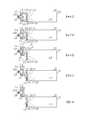
圖8A至圖8E為本發明另一實施例之電池組件的作動示意圖。如圖8A所示,於此實施例,操作部126可轉動地耦接活動板120’於鄰近第一卡合部122的一端,操作部126係受力(例如供使用者推壓)以驅使活動板120’轉動,進而解除第二卡合部124及卡止件120的卡合。具體而言,操作部126與活動板120’為兩個相互耦接的部件。活動板120'具有間隔設置於相對兩端的第一卡合部122及第二卡合部124,且操作部126可轉動地耦接活動板120’,使得第二卡合部124、第一卡合部122及操作部126具有類似前述實施例的配置。於此實施例,操作部126可具有例如弓形的彎折狀。操作部126於彎折點藉由轉軸160可轉動地耦接電池蓋130(或端部),且操作部126的一端藉由轉軸150可轉動地耦接活動板120’,使得操作部126相對於端部轉動時帶動活動板120’轉動。8A to 8E are schematic diagrams of the operation of the battery assembly according to another embodiment of the present invention. As shown in FIG. 8A, in this embodiment, the operating
於後參考圖8A至圖8E著重說明操作部126的作動,其餘電池組件的操作可參考前述實施例的相關說明。如圖8A所示,電池單元實質完全安裝於電池固定座,且藉由鎖具220的鎖定限制卡止件210的移動,而使卡止部212與電池單元的第一卡合部122保持卡合,以限制電池單元相對於電池固定座移動而定位於第一位置,即無法拆卸的位置。此時,操作部126朝電池固定座的方向彎曲,即操作部126的自由端較其轉軸160接近電池固定座。Hereinafter, referring to FIGS. 8A to 8E, the operation of the operating
如圖8B所示,鎖具220由鎖定狀態改變成解鎖狀態,驅動軸回縮帶動卡止件210沿解鎖方向D1朝容置空間2342內移動遠離第一卡合部122而解除卡合。此時,電池單元與電池固定座之間缺乏卡合機制,容許電池單元沿脫離方向D2相對於電池固定座移動,例如藉由重力向下移動。由於第二卡合部124較第一卡合部122朝卡合件210突出,使得電池單元相對於電池固定座移動至卡止部212與第二卡合部124卡合而定位於第二位置,如圖8C所示。As shown in FIG. 8B, the
如圖8C所示,當電池單元定位於第二位置時,由於第二卡合部124可相對於電池110的端部移動,使用者可施加外力F於操作部126,例如朝遠離電池固定座的方向推壓操作部126,使得操作部126以轉軸160為中心轉動,進而使連接活動板120’鄰近第一卡合部122的一端朝接近電池固定座的方向移動,而帶動活動板120’以軸部128為轉動中心沿順時鐘方向R轉動,進而帶動第二卡合部124轉動脫離卡合部212,如圖8D所示。此時,電池單元與電池固定座之間缺乏卡合機制,容許電池單元相對於電池固定座沿脫離方向再次移動,例如藉由重力向下移動,而自電池固定座拆卸,如圖8E所示。此外,本實施例的電池單元可具有前述實施例說明的彈性件140(於此未繪示),在解除外力F後,彈性件140可提供回復力於第二卡合部124,使得活動板120’反向旋轉而使第二卡合部124朝電池固定座的方向移動,進而帶動操作部126回到自由端較其轉軸160接近電池固定座的位置。As shown in FIG. 8C, when the battery unit is positioned at the second position, since the second
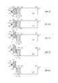
圖9A至圖9E為本發明另一實施例之電池組件的作動示意圖。如圖9A所示,於此實施例,第一卡合部122及第二卡合部124分別設置於電池110的端部,亦即第一卡合部122及第二卡合部124可為分離的兩個部件,而非整合於前述的活動板120、120’。舉例而言,第一卡合部122可為形成於電池蓋130的卡勾或卡合面,而第二卡合部124為可移動地設置於電池蓋130的部件。於此實施例,電池蓋130較佳具有通道部138,第二卡合部124可於通道部138中移動以相對於第一卡合部122移動。舉例而言,第二卡合部124的中間部分位於通道部138中,且兩端分別突出於電池蓋130,以作為與卡止件210卡合的部分及供使用者操作的操作部126。於此實施例,第二卡合部124相對於電池蓋130(或端部)為水平移動(或側向移動),即移動方向與電池單元的脫離方向實質垂直。9A to 9E are schematic diagrams of the operation of the battery assembly according to another embodiment of the present invention. As shown in FIG. 9A, in this embodiment, the first engaging
於後參考圖9A至圖9E著重說明第二卡合部124的作動,其餘電池組件的操作可參考前述實施例的相關說明。如圖9A所示,電池單元實質完全安裝於電池固定座,且藉由鎖具220的鎖定限制卡止件210的移動,而使卡止部212與電池單元的第一卡合部122保持卡合,以限制電池單元相對於電池固定座移動而定位於第一位置,即無法拆卸的位置。此時,第二卡合部124於脫離方向D2的投影至少部分在第一卡合部122端部的外側,亦即第二卡合部124較第一卡合部122朝卡止件210突出。Hereinafter, referring to FIGS. 9A to 9E, the operation of the second
如圖9B所示,鎖具220由鎖定狀態改變成解鎖狀態,驅動軸回縮帶動卡止件210沿解鎖方向D1朝容置空間2342內移動遠離第一卡合部122而解除卡合。此時,電池單元與電池固定座之間缺乏卡合機制,容許電池單元相對於電池固定座沿脫離方向D2移動,例如藉由重力向下移動。由於第二卡合部124較第一卡合部122朝卡合件210突出,使得電池單元相對於電池固定座移動至卡止部212與第二卡合部124卡合而定位於第二位置,如圖9C所示。As shown in FIG. 9B, the
如圖9C所示,當電池單元定位於第二位置時,容許第二卡合部124相對於第一卡合部122向電池110的內側移動,以解除與卡止件210的卡合。具體而言,使用者可施加外力F於第二卡合部124的操作部126,例如朝遠離電池固定座的方向推移操作部126,使得第二卡合部124在通道部138中沿施力方向(或平行於卡止件210的移動方向)移動而脫離卡合部212,如圖9D所示。亦即,第二卡合部124朝電池110的內側回縮,而使第二卡合部124相對於電池蓋130朝卡止件210突出的長度減少。此時,電池單元與電池固定座之間缺乏卡合機制,容許電池單元相對於電池固定座沿脫離方向D2再次移動,例如藉由重力向下移動,而自電池固定座拆卸,如圖9E所示。此外,本實施例的電池單元可具有前述實施例說明的彈性件140(於此未繪示),在解除外力F後,彈性件140可提供回復力於第二卡合部124,使得第二卡合部124反向移動而回到第二卡合部124較第一卡合部122接近電池固定座的位置。As shown in FIG. 9C, when the battery unit is positioned at the second position, the second
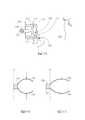
圖10A至圖10E為本發明另一實施例之電池組件於脫離方向D2的剖面及仰視的作動示意圖。如圖10A所示,於此實施例,第一卡合部122及第二卡合部124為分離的兩個部件,且第二卡合部124側向移動的方向與圖9A所示的實施例不同。類似於圖9A的實施例,第一卡合部122可為形成於電池蓋130的卡勾或卡合面,且第二卡合部124可相對於電池蓋130側向移動。電池單元更包含操作部170,操作部170對應第二卡合部124設置。操作部170係受力(例如供使用者推壓)以驅使第二卡合部124相對於第一卡合部122向電池110側向移動。具體而言,第二卡合部124的移動方向較佳與電池單元的脫離方向及卡止件210的移動方向垂直,亦即第二卡合部124的移動方向、卡止件210的移動方向及電池單元的脫離方向可分別代表XYZ三維空間的X軸、Y軸及Z軸的方向。10A to 10E are schematic diagrams of the operation of the battery assembly in the detachment direction D2 in the cross-section and bottom view according to another embodiment of the present invention. As shown in FIG. 10A, in this embodiment, the first engaging
於後參考圖10A至圖10E著重說明第二卡合部124的作動,其餘電池組件的操作可參考前述實施例的相關說明。如圖10A所示,電池單元實質完全安裝於電池固定座,且藉由鎖具220的鎖定限制卡止件210的移動,而使卡止部212與電池單元的第一卡合部122保持卡合,以限制電池單元相對於電池固定座移動而定位於第一位置,即無法拆卸的位置。此時,第二卡合部124於脫離方向D2的投影至少部分在第一卡合部122端部的外側,亦即第二卡合部124較第一卡合部122朝卡止件210突出。Hereinafter, referring to FIGS. 10A to 10E, the operation of the second
如圖10B所示,鎖具220由鎖定狀態改變成解鎖狀態,驅動軸回縮帶動卡止件210沿解鎖方向D1朝容置空間2342內移動遠離第一卡合部122而解除卡合。此時,電池單元與電池固定座之間缺乏卡合機制,容許電池單元相對於電池固定座沿脫離方向D2移動,例如藉由重力向下移動。由於第二卡合部124較第一卡合部122朝卡合件210突出,使得電池單元相對於電池固定座移動至卡止部212與第二卡合部124卡合而定位於第二位置,如圖10C所示。As shown in FIG. 10B, the
如圖10C所示,當電池單元定位於第二位置時,容許第二卡合部124相對於第一卡合部122向電池110側向移動,以使第二卡合部124與卡止件210錯位而解除卡合。具體而言,使用者可施加外力F於操作部170,例如沿電池110的短軸方向朝電池110內側推移操作部170,使得第二卡合部124沿施力方向移動而與卡合部212發生錯位,如圖10D所示。亦即,第二卡合部124相對於電池蓋130朝卡止件210突出的長度並未改變,而是位置改變,以與卡合件210形成錯位,例如第二卡合部124於脫離方向D2的投影與卡止件210不重疊。於此實施例,第二卡合部124側向移動的方向實質垂直於脫離方向D1及解鎖方向D2。此時,電池單元與電池固定座之間缺乏卡合機制,容許電池單元相對於電池固定座沿解鎖方向D2再次移動,例如藉由重力向下移動,而自電池固定座拆卸,如圖10E所示。此外,本實施例的電池單元可具有前述實施例說明的彈性件140(於此未繪示),在解除外力F後,彈性件140可提供回復力於第二卡合部124,使得第二卡合部124反向移動而回到原本位置。As shown in FIG. 10C, when the battery unit is positioned at the second position, the second
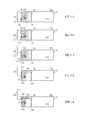
圖11A至圖11E為本發明另一實施例之電池組件的作動示意圖。如圖11A所示,於此實施例,電池組件的鎖具180是設置於電池單元10以耦接第一卡合部122。鎖具180於鎖定狀態時,限制卡止件210與第一卡合部122相對移動而維持卡合。鎖具180於解鎖狀態時,帶動第一卡合部122移動,以解除卡止件210與第一卡合部122的卡合。換句話說,於此實施例,卡止件210可為固定件,第一卡合部122及第二卡合部124為活動件。具體而言,鎖具180可具有與鎖具220類似的結構,且鎖具220的驅動軸224可用作為本實施例中的第一卡合部122,使得第一卡合部122可依據鎖具180的鎖定伸長或解鎖回縮,以改變相對於卡止件210的位置而形成卡合或解除卡合。舉例而言,第二卡合部124可具有類似圖9A的結構,以容許第二卡合部124相對於電池110的端部前後移動,但不以此為限。第二卡合部124亦可具有類似圖10A的結構,以容許第二卡合部124相對於電池110的端部側向移動。11A to 11E are schematic diagrams of the operation of a battery assembly according to another embodiment of the present invention. As shown in FIG. 11A, in this embodiment, the
於後參考圖11A至圖11E著重說明電池組件的操作。如圖11A所示,電池單元實質完全安裝於電池固定座,且藉由鎖具180的鎖定限制第一卡合部122的移動,而使電池單元的第一卡合部122與卡止件210的卡止部212保持卡合,以限制電池單元相對於電池固定座移動而定位於第一位置,即無法拆卸的位置。此時,第二卡合部124與第一卡合部122在脫離方向D2上的投影彼此至少部分重疊,並各與卡止件210的卡止部212至少部分重疊。The operation of the battery assembly will be emphatically described later with reference to FIGS. 11A to 11E. As shown in FIG. 11A, the battery unit is substantially completely installed in the battery holder, and the movement of the first engaging
如圖11B所示,鎖具180由鎖定狀態改變成解鎖狀態,驅動軸回縮帶動第一卡合部122沿解鎖方向D1朝電池110的內側移動遠離卡合部212而解除卡合。此時,電池單元與電池固定座之間缺乏卡合機制,容許電池單元相對於電池固定座沿脫離方向D2移動,例如藉由重力向下移動,直到第二卡合部124與卡止部212卡合而使電池單元定位於第二位置,如圖11C所示。亦即,鎖具180由鎖定狀態改變成解鎖狀態,帶動第一卡合部122遠離第二卡合部124的移動路徑上,使得電池單元移動至第二卡合部124與卡止部212發生干涉(或卡合)而停止移動被定位在第二位置。As shown in FIG. 11B, the
如圖11C所示,當電池單元定位於第二位置時,容許第二卡合部124相對於第一卡合部122向電池110的內側移動,以解除與卡止件210的卡合。具體而言,使用者可施加外力F於第二卡合部124的操作部,例如朝遠離電池固定座的方向推移操作部,使得第二卡合部124在通道部138中沿施力方向(或平行於第一卡合部122的移動方向)移動而脫離卡合部212,如圖11D所示。此時,電池單元與電池固定座之間缺乏卡合機制,容許電池單元相對於電池固定座沿脫離方向D2再次移動,例如藉由重力向下移動,而自電池固定座拆卸,如圖11E所示。此外,本實施例的電池單元可具有前述實施例說明的彈性件140(於此未繪示),在解除外力F後,彈性件140可提供回復力於第二卡合部124,使得第二卡合部124反向移動而回到原本位置。As shown in FIG. 11C, when the battery unit is positioned at the second position, the second
此外,於上述的實施例中,可藉由其他連動機構與操作部耦接,以改變施力以控制操作部的作用方向。圖12A為本發明另一實施例之電池組件的示意圖。於此實施例,電池單元更包含作用件190。作用件190可活動地設置於電池單元的側邊,且作用件190受外力F推抵操作部126以帶動第二卡合部124遠離卡止件210而解除卡合,外力F的施加方向垂直於解鎖方向D1及/或脫離方向D2。舉例而言,作用件190的一端可耦接圖7A的操作部126,且作用件190的另一端可連接於電池單元的電池蓋130(或電池110)。作用件190至少局部裸露於電池單元的外側,以供使用者施加外力F,進而帶動操作部126的移動。於後,參考圖12B及圖12C,說明操作部126與作用件190的作動關係。In addition, in the above-mentioned embodiments, other linkage mechanisms can be coupled with the operating portion to change the force applied to control the direction of action of the operating portion. FIG. 12A is a schematic diagram of a battery assembly according to another embodiment of the invention. In this embodiment, the battery unit further includes a
如圖12B所示,作用件190較佳為設置於電池單元兩側的可變形驅動板或彈片,且作用件190的兩端分別耦接操作部126及電池蓋130(或電池110)。於此實施例,作用件190可受力彈性變形,以推抵操作部126,使得操作部126相對於參考面P沿移動方向D3移動至如圖12C所示的位置。舉例而言,當脫離方向D2為向下時,藉由作用件190的設置,使用者可在單手支撐住電池單元的狀況下,同時運用拇指及食指施力於設置在電池單元側邊的作用件190,使得作用件190活動(例如變形伸長)而朝電池固定座推抵操作部126,進而帶動第二卡合部124轉動遠離卡止件210而解除卡合。當外力F釋放時,藉由作用件190的回復力可使操作部126及作用件190回到圖12B所示的位置。換言之,於圖12A的實施例中,移動方向D3與圖7C的外力F的施力向相同,藉由作用件190的設置,使得施加於作用件190的外力F的施加方向垂直於解鎖方向D1及脫離方向D2,以增加操作的便利性。作用件190不以實施例所示的可變形驅動板或彈片為限,且作用件190的活動也不以變形為限。於其他實施例,作用件可實施為任何合宜的連動機構,例如與操作部126可轉動耦接的一或多個連動件,以藉由連動件的轉動及/或移動控制操作部126的移動,進而增進操作的便利性。As shown in FIG. 12B, the acting
圖13A為本發明另一實施例之電池組件的示意圖;圖13B及圖13C顯示操作部126與作用件190’的作動關係,其中圖13B及圖13C為沿電池單元脫離方向D2觀看之平面示意圖。如圖13A至圖13B所示,於此實施例,作用件190’包含複數連動件192、194及彈性件196,以構成與操作部126一同作用的連動構件。舉例而言,連動件192、194可實施為連桿形式,且彈性件196可實施為扭簧。於此實施例,兩組作用件190’較佳分別設置於電池單元的兩側。其中且連動件192自電池單元側邊朝操作部126延伸並樞接連動件194,扭簧式的彈性件196設置於連動件192及194的樞接處,且連動件194相對於連動件192的另一側耦接操作部126。作用件190’可樞接於電池的殼體或電池蓋130,扭簧的兩延伸臂分別靠抵連動件192、194。如圖13B及圖13C所示,當作用件190’受力時,例如使用者施加外力F於連動件192的自由端,以扭簧樞接處旋轉並壓縮扭簧,進而相對於參考面沿移動方向D3推抵操作部126,以使活動板120相應旋轉,帶動第二卡合部124移動脫離卡止件210而解除卡合,以容許電池單元完全脫離電池固定座。當外力F釋放時,藉由扭簧(即彈性件196)的回復力可使操作部126及作用件190’回到圖13B所示的位置。13A is a schematic diagram of a battery assembly according to another embodiment of the present invention; FIGS. 13B and 13C show the operation relationship between the operating
本發明已由上述實施例加以描述,然而上述實施例僅為例示目的而非用於限制。熟此技藝者當知在不悖離本發明精神下,於此特別說明的實施例可有例示實施例的其他修改。因此,本發明範疇亦涵蓋此類修改且僅由所附申請專利範圍限制。The present invention has been described by the above-mentioned embodiments, but the above-mentioned embodiments are only for illustrative purposes and not for limitation. Those skilled in the art should know that without departing from the spirit of the present invention, the embodiments specifically described herein may have other modifications to the illustrated embodiments. Therefore, the scope of the present invention also covers such modifications and is only limited by the scope of the attached patent application.
1電池組件 10電池單元 110電池 112、114端部 120、120’活動板 122第一卡合部 124第二卡合部 126操作部 128軸部 129定位孔 130、130’電池蓋 132軸孔 134導槽 135側壁 136導引壁 138通道部 140彈性件 150、160轉軸 170操作部 180鎖具 190、190’作用件 192、194連動件 196彈性件 20電池固定座 210卡止件 212卡止部 214耦接孔 214a第一孔部 214b第二孔部 220鎖具 222鎖本體 224驅動軸 226頸部段 228頭部段 230基座 232第一側板 2322通孔 234座體 2342容置空間 236第二側板 2362擋止面 2364開口 2366導塊 2367外壁 2368導引面 240彈性件 D1解鎖方向 D2脫離方向 D3移動方向 F外力 P參考面1
圖1為本發明一實施例之電池組件之示意圖。 圖2為圖1之電池單元的局部放大分解示意圖。 圖2A為圖2之活動板的另一視角之示意圖。 圖3為圖1之電池固定座的分解示意圖。 圖4A及圖4B分別為電池固定座將電池單元定位於第一位置及第二位置的剖面示意圖。 圖5A及圖5B為本發明不同實施例之電池組件之局部剖面示意圖。 圖6A及圖6B為本發明不同實施例之電池組件之局部示意圖。 圖7A至圖7E為本發明一實施例之電池組件的作動示意圖。 圖8A至圖8E為本發明另一實施例之電池組件的作動示意圖。 圖9A至圖9E為本發明另一實施例之電池組件的作動示意圖。 圖10A至圖10E為本發明另一實施例之電池組件的剖面及仰視的作動示意圖。 圖11A至圖11E為本發明另一實施例之電池組件的作動示意圖。 圖12A為本發明另一實施例之電池組件的示意圖。 圖12B及圖12C為本發明一實施例之操作部與作用件的作動示意圖。 圖13A為本發明另一實施例之電池組件的示意圖。 圖13B及圖13C為本發明另一實施例之操作部與作用件的作動示意圖。FIG. 1 is a schematic diagram of a battery assembly according to an embodiment of the invention. Fig. 2 is a partial enlarged and exploded schematic diagram of the battery unit of Fig. 1. FIG. 2A is a schematic diagram of the movable panel of FIG. 2 from another perspective. Fig. 3 is an exploded schematic view of the battery holder of Fig. 1. 4A and 4B are schematic cross-sectional views of the battery holder positioning the battery unit at the first position and the second position, respectively. 5A and 5B are schematic partial cross-sectional views of battery modules according to different embodiments of the present invention. 6A and 6B are partial schematic diagrams of battery assemblies according to different embodiments of the present invention. 7A to 7E are schematic diagrams of the operation of the battery assembly according to an embodiment of the present invention. 8A to 8E are schematic diagrams of the operation of the battery assembly according to another embodiment of the present invention. 9A to 9E are schematic diagrams of the operation of the battery assembly according to another embodiment of the present invention. 10A to 10E are schematic diagrams showing the operation of the battery assembly in cross section and bottom view according to another embodiment of the present invention. 11A to 11E are schematic diagrams of the operation of a battery assembly according to another embodiment of the present invention. FIG. 12A is a schematic diagram of a battery assembly according to another embodiment of the invention. 12B and 12C are schematic diagrams of the operation of the operating part and the acting member according to an embodiment of the present invention. FIG. 13A is a schematic diagram of a battery assembly according to another embodiment of the invention. 13B and 13C are schematic diagrams of the operation of the operating part and the acting member according to another embodiment of the present invention.
1電池組件 10電池單元 110電池 112、114端部 122第一卡合部 124第二卡合部 20電池固定座 210卡止件1
Claims (20)
Translated fromChinesePriority Applications (5)
| Application Number | Priority Date | Filing Date | Title |
|---|---|---|---|
| TW108138493ATWI728524B (en) | 2019-10-24 | 2019-10-24 | Battery assembly |
| US16/808,029US11469474B2 (en) | 2019-10-24 | 2020-03-03 | Battery assembly |
| EP20161741.2AEP3812254B1 (en) | 2019-10-24 | 2020-03-09 | Battery assembly |
| ES20161741TES3023166T3 (en) | 2019-10-24 | 2020-03-09 | Battery assembly |
| JP2020041356AJP6944002B2 (en) | 2019-10-24 | 2020-03-10 | Battery assembly structure |
Applications Claiming Priority (1)
| Application Number | Priority Date | Filing Date | Title |
|---|---|---|---|
| TW108138493ATWI728524B (en) | 2019-10-24 | 2019-10-24 | Battery assembly |
Publications (2)
| Publication Number | Publication Date |
|---|---|
| TW202118119A TW202118119A (en) | 2021-05-01 |
| TWI728524Btrue TWI728524B (en) | 2021-05-21 |
Family
ID=69784123
Family Applications (1)
| Application Number | Title | Priority Date | Filing Date |
|---|---|---|---|
| TW108138493ATWI728524B (en) | 2019-10-24 | 2019-10-24 | Battery assembly |
Country Status (5)
| Country | Link |
|---|---|
| US (1) | US11469474B2 (en) |
| EP (1) | EP3812254B1 (en) |
| JP (1) | JP6944002B2 (en) |
| ES (1) | ES3023166T3 (en) |
| TW (1) | TWI728524B (en) |
Families Citing this family (8)
| Publication number | Priority date | Publication date | Assignee | Title |
|---|---|---|---|---|
| DE102019204572B3 (en)* | 2019-04-01 | 2020-08-06 | Brose Antriebstechnik GmbH & Co. Kommanditgesellschaft, Berlin | Locking device for locking a power supply unit for a bicycle |
| DE102019211613B4 (en)* | 2019-08-02 | 2021-03-18 | Robert Bosch Gmbh | Holding device for a counter element and two-wheeled vehicle |
| US11565769B2 (en)* | 2020-12-11 | 2023-01-31 | Specialized Bicycle Components, Inc. | 3-position battery latching system |
| JP7701206B2 (en)* | 2021-07-30 | 2025-07-01 | ヤマハ発動機株式会社 | Battery device and electric bicycle |
| CN114715310A (en)* | 2022-04-08 | 2022-07-08 | 浙江欧凯车业有限公司 | A locking mechanism and electric vehicle |
| DE202022105039U1 (en)* | 2022-09-07 | 2022-09-15 | Biketec Gmbh | Electric bicycle with drive battery and drive battery arrangement for an electric bicycle |
| EP4375175A1 (en)* | 2022-11-25 | 2024-05-29 | Trend Power Technology (Changshu) Inc. | Fixing device for a battery module |
| CN115959227A (en)* | 2023-01-09 | 2023-04-14 | 深圳飞道科技发展有限公司 | Battery mounting structure and electric bicycle |
Citations (3)
| Publication number | Priority date | Publication date | Assignee | Title |
|---|---|---|---|---|
| TW201800303A (en)* | 2016-06-29 | 2018-01-01 | 島野股份有限公司 | Battery unit for bicycle capable of reducing the influence of contact with obstacles (such as stones or gravels) bouncing from the road surface |
| CN108028331A (en)* | 2015-10-02 | 2018-05-11 | 日立汽车系统株式会社 | Battery pack |
| TW201932357A (en)* | 2018-01-19 | 2019-08-16 | 日商島野股份有限公司 | Battery holder |
Family Cites Families (18)
| Publication number | Priority date | Publication date | Assignee | Title |
|---|---|---|---|---|
| JP2002117818A (en) | 2000-10-11 | 2002-04-19 | Sony Corp | Mounting device of battery |
| JP4556539B2 (en)* | 2004-08-06 | 2010-10-06 | 株式会社デンソーウェーブ | Battery pack |
| US8162191B2 (en)* | 2008-04-21 | 2012-04-24 | Shimano Inc. | Bicycle battery holder |
| TWM458338U (en) | 2012-12-24 | 2013-08-01 | Darfon Electronics Corp | Battery device with containing function and electrical bicycle thereof |
| TWI501449B (en) | 2014-08-04 | 2015-09-21 | Darfon Electronics Corp | Battery module and battery assembly thereof |
| DE202015003010U1 (en) | 2015-04-24 | 2015-06-05 | Derby Cycle Werke Gmbh | Vehicle frame, in particular bicycle frame with a down tube |
| TWM514946U (en) | 2015-10-01 | 2016-01-01 | 菲力工業股份有限公司 | Electric bicycle frame |
| US10183591B2 (en) | 2015-12-18 | 2019-01-22 | Darfon Electronics (Suzhou) Co., Ltd. | Electric bicycle and battery lift mechanism and battery carrying device thereof |
| TWM525556U (en) | 2016-03-17 | 2016-07-11 | Td Hitech Energy Inc | Battery holder structure |
| JP6682387B2 (en) | 2016-06-30 | 2020-04-15 | 株式会社シマノ | Battery holder, battery unit, and battery component including them |
| JP6705708B2 (en)* | 2016-06-30 | 2020-06-03 | 株式会社シマノ | Battery holder, battery unit, and battery component including them |
| DE102016213903B3 (en) | 2016-07-28 | 2018-01-11 | Robert Bosch Gmbh | Retaining element for use on an accumulator and associated holding device |
| DE102018006690A1 (en) | 2017-08-29 | 2019-02-28 | Marquardt Verwaltungs-Gmbh | vehicle |
| CN110126968B (en) | 2018-02-09 | 2020-11-06 | 捷安特电动车(昆山)有限公司 | Battery locking structure |
| CN110197879A (en) | 2018-02-26 | 2019-09-03 | 株式会社岛野 | Battery force application device and manpower driving vehicle with same |
| DE112019001106T5 (en) | 2018-03-02 | 2020-11-19 | Panasonic Intellectual Property Management Co., Ltd. | Battery device, motor unit and electric bike |
| CN209567029U (en) | 2018-07-06 | 2019-11-01 | 太普动力新能源(常熟)股份有限公司 | Electric bicycle frame |
| TWM598532U (en) | 2020-03-19 | 2020-07-11 | 宏碁股份有限公司 | Dual-purpose battery module |
- 2019
- 2019-10-24TWTW108138493Apatent/TWI728524B/enactive
- 2020
- 2020-03-03USUS16/808,029patent/US11469474B2/enactiveActive
- 2020-03-09ESES20161741Tpatent/ES3023166T3/enactiveActive
- 2020-03-09EPEP20161741.2Apatent/EP3812254B1/enactiveActive
- 2020-03-10JPJP2020041356Apatent/JP6944002B2/enactiveActive
Patent Citations (3)
| Publication number | Priority date | Publication date | Assignee | Title |
|---|---|---|---|---|
| CN108028331A (en)* | 2015-10-02 | 2018-05-11 | 日立汽车系统株式会社 | Battery pack |
| TW201800303A (en)* | 2016-06-29 | 2018-01-01 | 島野股份有限公司 | Battery unit for bicycle capable of reducing the influence of contact with obstacles (such as stones or gravels) bouncing from the road surface |
| TW201932357A (en)* | 2018-01-19 | 2019-08-16 | 日商島野股份有限公司 | Battery holder |
Also Published As
| Publication number | Publication date |
|---|---|
| EP3812254A1 (en) | 2021-04-28 |
| EP3812254C0 (en) | 2025-04-16 |
| JP6944002B2 (en) | 2021-10-06 |
| US11469474B2 (en) | 2022-10-11 |
| TW202118119A (en) | 2021-05-01 |
| US20210126230A1 (en) | 2021-04-29 |
| EP3812254B1 (en) | 2025-04-16 |
| JP2021068693A (en) | 2021-04-30 |
| ES3023166T3 (en) | 2025-05-30 |
Similar Documents
| Publication | Publication Date | Title |
|---|---|---|
| TWI728524B (en) | Battery assembly | |
| TWI759812B (en) | Battery assembly | |
| EP2111777B1 (en) | Coupling device for a baby crib frame structure | |
| US7423869B2 (en) | Hard disk drawing device | |
| US8671721B2 (en) | Lock structure | |
| TWI762092B (en) | Power device and server | |
| CN113027235B (en) | Lock tongue module and modular lock | |
| WO2022041148A1 (en) | Flip cover mechanism, housing, electronic device, movable platform, and camera | |
| CN102525038B (en) | A kind of bracelet of seat belt apparatus | |
| US8899700B2 (en) | Housing having a carrier device | |
| CN112825379B (en) | Battery pack | |
| CN116234221B (en) | Shell assembly, bearing piece and electronic device comprising same | |
| TWI771193B (en) | Unlock mechanism and server | |
| TWI427460B (en) | Battery cover lock structure | |
| TWI564696B (en) | Electronic device | |
| TW202508395A (en) | Clasp mechanism and electronic device module | |
| CN213845434U (en) | Unlock Components, Batteries, Power Kits, and Removable Platforms | |
| CN114079117B (en) | Battery assembly | |
| KR101890553B1 (en) | Latch assembly of non-bolting for door lever lock | |
| CN211818705U (en) | Puzzle lock | |
| CN113544903A (en) | Unblock subassembly, battery, energy supply external member and movable platform | |
| CN117458074B (en) | Electronic equipment, battery compartment and cabin cover thereof | |
| TW201622523A (en) | Latch device and server using the same | |
| TWI744062B (en) | Locking assembly and box having the same | |
| CN117832025A (en) | Interlocking device |