TWI727445B - Installation structure of brake disc for railway vehicle and brake disc unit using the installation structure - Google Patents
Installation structure of brake disc for railway vehicle and brake disc unit using the installation structureDownload PDFInfo
- Publication number
- TWI727445B TWI727445BTW108135822ATW108135822ATWI727445BTW I727445 BTWI727445 BTW I727445BTW 108135822 ATW108135822 ATW 108135822ATW 108135822 ATW108135822 ATW 108135822ATW I727445 BTWI727445 BTW I727445B
- Authority
- TW
- Taiwan
- Prior art keywords
- brake disc
- elastic member
- flange
- nut
- outer peripheral
- Prior art date
Links
Images


Classifications
- F—MECHANICAL ENGINEERING; LIGHTING; HEATING; WEAPONS; BLASTING
- F16—ENGINEERING ELEMENTS AND UNITS; GENERAL MEASURES FOR PRODUCING AND MAINTAINING EFFECTIVE FUNCTIONING OF MACHINES OR INSTALLATIONS; THERMAL INSULATION IN GENERAL
- F16D—COUPLINGS FOR TRANSMITTING ROTATION; CLUTCHES; BRAKES
- F16D65/00—Parts or details
- F16D65/02—Braking members; Mounting thereof
- F16D65/12—Discs; Drums for disc brakes
- F16D65/123—Discs; Drums for disc brakes comprising an annular disc secured to a hub member; Discs characterised by means for mounting
- F16D65/124—Discs; Drums for disc brakes comprising an annular disc secured to a hub member; Discs characterised by means for mounting adapted for mounting on the wheel of a railway vehicle
- B—PERFORMING OPERATIONS; TRANSPORTING
- B61—RAILWAYS
- B61H—BRAKES OR OTHER RETARDING DEVICES SPECIALLY ADAPTED FOR RAIL VEHICLES; ARRANGEMENT OR DISPOSITION THEREOF IN RAIL VEHICLES
- B61H5/00—Applications or arrangements of brakes with substantially radial braking surfaces pressed together in axial direction, e.g. disc brakes
- F—MECHANICAL ENGINEERING; LIGHTING; HEATING; WEAPONS; BLASTING
- F16—ENGINEERING ELEMENTS AND UNITS; GENERAL MEASURES FOR PRODUCING AND MAINTAINING EFFECTIVE FUNCTIONING OF MACHINES OR INSTALLATIONS; THERMAL INSULATION IN GENERAL
- F16B—DEVICES FOR FASTENING OR SECURING CONSTRUCTIONAL ELEMENTS OR MACHINE PARTS TOGETHER, e.g. NAILS, BOLTS, CIRCLIPS, CLAMPS, CLIPS OR WEDGES; JOINTS OR JOINTING
- F16B43/00—Washers or equivalent devices; Other devices for supporting bolt-heads or nuts
- F—MECHANICAL ENGINEERING; LIGHTING; HEATING; WEAPONS; BLASTING
- F16—ENGINEERING ELEMENTS AND UNITS; GENERAL MEASURES FOR PRODUCING AND MAINTAINING EFFECTIVE FUNCTIONING OF MACHINES OR INSTALLATIONS; THERMAL INSULATION IN GENERAL
- F16B—DEVICES FOR FASTENING OR SECURING CONSTRUCTIONAL ELEMENTS OR MACHINE PARTS TOGETHER, e.g. NAILS, BOLTS, CIRCLIPS, CLAMPS, CLIPS OR WEDGES; JOINTS OR JOINTING
- F16B5/00—Joining sheets or plates, e.g. panels, to one another or to strips or bars parallel to them
- F16B5/02—Joining sheets or plates, e.g. panels, to one another or to strips or bars parallel to them by means of fastening members using screw-thread
- F16B5/0258—Joining sheets or plates, e.g. panels, to one another or to strips or bars parallel to them by means of fastening members using screw-thread using resiliently deformable sleeves, grommets or inserts
- F—MECHANICAL ENGINEERING; LIGHTING; HEATING; WEAPONS; BLASTING
- F16—ENGINEERING ELEMENTS AND UNITS; GENERAL MEASURES FOR PRODUCING AND MAINTAINING EFFECTIVE FUNCTIONING OF MACHINES OR INSTALLATIONS; THERMAL INSULATION IN GENERAL
- F16D—COUPLINGS FOR TRANSMITTING ROTATION; CLUTCHES; BRAKES
- F16D65/00—Parts or details
- F16D65/02—Braking members; Mounting thereof
- F16D65/12—Discs; Drums for disc brakes
- F—MECHANICAL ENGINEERING; LIGHTING; HEATING; WEAPONS; BLASTING
- F16—ENGINEERING ELEMENTS AND UNITS; GENERAL MEASURES FOR PRODUCING AND MAINTAINING EFFECTIVE FUNCTIONING OF MACHINES OR INSTALLATIONS; THERMAL INSULATION IN GENERAL
- F16D—COUPLINGS FOR TRANSMITTING ROTATION; CLUTCHES; BRAKES
- F16D65/00—Parts or details
- F16D65/02—Braking members; Mounting thereof
- F16D2065/13—Parts or details of discs or drums
- F16D2065/1304—Structure
- F16D2065/1308—Structure one-part
- F—MECHANICAL ENGINEERING; LIGHTING; HEATING; WEAPONS; BLASTING
- F16—ENGINEERING ELEMENTS AND UNITS; GENERAL MEASURES FOR PRODUCING AND MAINTAINING EFFECTIVE FUNCTIONING OF MACHINES OR INSTALLATIONS; THERMAL INSULATION IN GENERAL
- F16D—COUPLINGS FOR TRANSMITTING ROTATION; CLUTCHES; BRAKES
- F16D65/00—Parts or details
- F16D65/02—Braking members; Mounting thereof
- F16D2065/13—Parts or details of discs or drums
- F16D2065/134—Connection
- F16D2065/1348—Connection resilient
- F—MECHANICAL ENGINEERING; LIGHTING; HEATING; WEAPONS; BLASTING
- F16—ENGINEERING ELEMENTS AND UNITS; GENERAL MEASURES FOR PRODUCING AND MAINTAINING EFFECTIVE FUNCTIONING OF MACHINES OR INSTALLATIONS; THERMAL INSULATION IN GENERAL
- F16D—COUPLINGS FOR TRANSMITTING ROTATION; CLUTCHES; BRAKES
- F16D65/00—Parts or details
- F16D65/02—Braking members; Mounting thereof
- F16D2065/13—Parts or details of discs or drums
- F16D2065/134—Connection
- F16D2065/1384—Connection to wheel hub
- F—MECHANICAL ENGINEERING; LIGHTING; HEATING; WEAPONS; BLASTING
- F16—ENGINEERING ELEMENTS AND UNITS; GENERAL MEASURES FOR PRODUCING AND MAINTAINING EFFECTIVE FUNCTIONING OF MACHINES OR INSTALLATIONS; THERMAL INSULATION IN GENERAL
- F16D—COUPLINGS FOR TRANSMITTING ROTATION; CLUTCHES; BRAKES
- F16D65/00—Parts or details
- F16D65/02—Braking members; Mounting thereof
- F16D2065/13—Parts or details of discs or drums
- F16D2065/134—Connection
- F16D2065/1388—Connection to shaft or axle
- F—MECHANICAL ENGINEERING; LIGHTING; HEATING; WEAPONS; BLASTING
- F16—ENGINEERING ELEMENTS AND UNITS; GENERAL MEASURES FOR PRODUCING AND MAINTAINING EFFECTIVE FUNCTIONING OF MACHINES OR INSTALLATIONS; THERMAL INSULATION IN GENERAL
- F16D—COUPLINGS FOR TRANSMITTING ROTATION; CLUTCHES; BRAKES
- F16D65/00—Parts or details
- F16D65/02—Braking members; Mounting thereof
- F16D2065/13—Parts or details of discs or drums
- F16D2065/134—Connection
- F16D2065/1392—Connection elements
- F16D2065/1396—Ancillary resilient elements, e.g. anti-rattle or retraction springs
- F—MECHANICAL ENGINEERING; LIGHTING; HEATING; WEAPONS; BLASTING
- F16—ENGINEERING ELEMENTS AND UNITS; GENERAL MEASURES FOR PRODUCING AND MAINTAINING EFFECTIVE FUNCTIONING OF MACHINES OR INSTALLATIONS; THERMAL INSULATION IN GENERAL
- F16D—COUPLINGS FOR TRANSMITTING ROTATION; CLUTCHES; BRAKES
- F16D65/00—Parts or details
- F16D65/02—Braking members; Mounting thereof
- F16D65/12—Discs; Drums for disc brakes
- F16D65/127—Discs; Drums for disc brakes characterised by properties of the disc surface; Discs lined with friction material
Landscapes
- Engineering & Computer Science (AREA)
- General Engineering & Computer Science (AREA)
- Mechanical Engineering (AREA)
- Braking Arrangements (AREA)
- Bolts, Nuts, And Washers (AREA)
Abstract
Translated fromChineseDescription
Translated fromChinese本發明,關於煞車碟盤的安裝構造,更詳細地說,是關於將環狀的煞車碟盤,安裝於「鐵道車輛的車輪」或者「固定於鐵道車輛之車軸的碟盤體」的構造。此外,本發明關於:使用該安裝構造的煞車碟盤單元。The present invention relates to the installation structure of the brake disc, more specifically, it relates to a structure in which a ring-shaped brake disc is attached to the "wheel of a railway vehicle" or "the disc body fixed to the axle of the railway vehicle". In addition, the present invention relates to a brake disc unit using this mounting structure.
傳統以來,使用碟煞作為鐵道車輛的制動裝置。碟煞,具備環狀的煞車碟盤、煞車襯。煞車碟盤,連結(鎖附)於鐵道車輛的車輪、或者連結(鎖附)於固定在車軸的碟盤體。將煞車襯壓附於煞車碟盤的滑動面。藉由煞車碟盤與煞車襯之間的摩擦,使車輪受到制動。Traditionally, disc brakes have been used as the braking device of railway vehicles. Disc brakes, with ring-shaped brake discs and brake linings. The brake disc is connected (locked) to the wheel of a railway vehicle or connected (locked) to the disc body fixed to the axle. Press the brake lining onto the sliding surface of the brake disc. The wheels are braked by the friction between the brake disc and the brake lining.
專利文獻1,揭示了藉由螺栓及螺帽而連結於車輪各側面的煞車碟盤。在該煞車碟盤、與螺栓的頭部或者螺帽之間,配置有碟型彈簧之類的彈性體。根據專利文獻1,藉由使彈性體的彈性係數合理化,能減輕對螺栓的彎曲負荷及拉伸負荷。
專利文獻2,揭示了車輪或碟盤體、與煞車碟盤之間的連結構造。該連結構造,在煞車碟盤與螺帽之間,配置有碟型彈簧。在車輪或者碟盤體與煞車碟盤之間的連結狀態中,碟型彈簧,配置成其凹面朝向螺帽的承受面(bearing surface),而接觸螺帽之承受面的外周部。根據專利文獻2,藉由使碟型彈簧接觸螺帽之承受面的外周部,能使螺栓的螺絲底之R部的應力集中降低。
作為配置於構件之間的彈性體,已提出了各種的方案。舉例來說,專利文獻3,揭示了當利用螺栓連結第1構件及第2構件時,配置於第1構件上下的彈性體。在專利文獻3中,上下的彈性體,分別具有作為碟型彈簧發揮功用的圓錐部。上側的彈性體,固定於螺栓的頭部及第1構件。As an elastic body arranged between members, various proposals have been made. For example,
此外,舉例來說,專利文獻4揭示了:夾介於被連結物與螺栓的頭部、或者螺帽之間的墊圈(碟型彈簧)。該碟型彈簧,具有按壓部、彈簧部。按壓部,接觸螺栓的頭部或者螺帽的承受面。彈簧部,具有面向被連結物的凹面,並且從按壓部朝向被連結物形成擴徑。按壓部的最大外徑,小於彈簧部的最大外徑。根據專利文獻4,可藉由該構造,使作用於按壓部的荷重,集中於彈簧部的中心部,能使彈簧部確實地形成壓縮變形。[先前技術文獻][專利文獻]In addition, for example,
[專利文獻1] 日本特許第4305296號公報[專利文獻2] 日本特許第4748390號公報[專利文獻3] 日本特開2010-060031號公報[專利文獻4] 日本特開2002-323029號公報[Patent Document 1] Japanese Patent No. 4305296[Patent Document 2] Japanese Patent No. 4748390[Patent Document 3] JP 2010-060031 A[Patent Document 4] JP 2002-323029 A
[發明欲解決之問題][Problem to be solved by invention]
專利文獻1及專利文獻2所揭示的鐵道車輛用煞車碟盤,在車輪的制動中,由於「與煞車襯之間產生的熱摩擦」而形成熱變形。如此一來,對「將煞車碟盤連結於車輪或者碟盤體的連結構件」的負荷將增加。為了減輕對連結構件的負荷,可利用如同各專利文獻所揭示的碟型彈簧(彈性體)。然而,譬如在「將連結部設在滑動面中央之中央連結型」的煞車碟盤中,由於用來配置碟型彈簧的空間受到限制,有時無法充分地降低碟型彈簧的彈簧常數。其結果,降低「對連結構件的負荷」變得不充分,而存在「連結構件的疲勞強度下降」的可能性。The brake discs for railway vehicles disclosed in
本發明課題在於:在「藉由連結構件而連結於被安裝構件的鐵道車輛用煞車碟盤」中,提升連結構件的疲勞強度。[解決問題之手段]The subject of the present invention is to improve the fatigue strength of the connecting member in "the brake disc for a railway vehicle connected to the mounted member by the connecting member".[Means to Solve the Problem]
本發明的安裝構造,是將環狀的煞車碟盤安裝於被安裝構件的構造。被安裝構件,可以是鐵道車輛的車輪,也可以是固定於鐵道車輛之車軸的碟盤體。安裝構造,具備連結構件、彈性構件。連結構件,將煞車碟盤連結於被安裝構件。連結構件,具有螺栓、螺帽。螺栓包含軸部。軸部,貫穿煞車碟盤及被安裝構件。螺帽,在煞車碟盤側安裝於軸部的端部。彈性構件,配置於螺帽與煞車碟盤之間。彈性構件,具有筒狀的構件本體、第1凸緣。軸部插入構件本體。第1凸緣,連接於構件本體之兩端部中的螺帽側的端部。第1凸緣,從構件本體朝外側突出,並接觸螺帽的外周部。[發明的效果]The attachment structure of the present invention is a structure in which a ring-shaped brake disc is attached to a member to be attached. The member to be mounted may be a wheel of a railway vehicle or a disc body fixed to the axle of the railway vehicle. The mounting structure includes a connecting member and an elastic member. The connecting member connects the brake disc to the mounted member. The connecting member has bolts and nuts. The bolt includes the shaft. The shaft penetrates the brake disc and the installed components. The nut is installed on the end of the shaft on the side of the brake disc. The elastic member is arranged between the nut and the brake disc. The elastic member has a cylindrical member body and a first flange. The shaft is inserted into the body of the component. The first flange is connected to the end on the nut side among the two ends of the component body. The first flange protrudes outward from the member body and contacts the outer peripheral portion of the nut.[Effects of the invention]
根據本發明,可在「藉由連結構件而連結於被安裝構件的鐵道車輛用煞車碟盤」中,提升連結構件的疲勞強度。According to the present invention, the fatigue strength of the connecting member can be improved in "the brake disc for a railway vehicle connected to the mounted member by the connecting member".
實施形態的安裝構造,是將環狀的煞車碟盤安裝於被安裝構件的構造。被安裝構件,可以是鐵道車輛的車輪,也可以是固定於鐵道車輛之車軸的碟盤體。安裝構造,具備連結構件、彈性構件。連結構件,將煞車碟盤連結於被安裝構件。連結構件,具有螺栓、螺帽。螺栓包含軸部。軸部,貫穿煞車碟盤及被安裝構件。螺帽,在煞車碟盤側安裝於軸部的端部。彈性構件,配置於螺帽與煞車碟盤之間。彈性構件,具有筒狀的構件本體、第1凸緣。軸部插入構件本體。第1凸緣,連接於構件本體之兩端部中的螺帽側的端部。第1凸緣,從構件本體朝向外側突出,並接觸螺帽的外周部(第1構造)。The attachment structure of the embodiment is a structure in which a ring-shaped brake disc is attached to a member to be attached. The member to be mounted may be a wheel of a railway vehicle or a disc body fixed to the axle of the railway vehicle. The mounting structure includes a connecting member and an elastic member. The connecting member connects the brake disc to the mounted member. The connecting member has bolts and nuts. The bolt includes the shaft. The shaft penetrates the brake disc and the installed components. The nut is installed on the end of the shaft on the side of the brake disc. The elastic member is arranged between the nut and the brake disc. The elastic member has a cylindrical member body and a first flange. The shaft is inserted into the body of the component. The first flange is connected to the end on the nut side among the two ends of the component body. The first flange protrudes outward from the member body and contacts the outer peripheral portion of the nut (first structure).
在第1構造中,於連結構件的螺帽與煞車碟盤之間,配置有構件本體、及具有第1凸緣的彈性構件。該彈性構件,夾介於「安裝在螺栓之軸部的螺帽」與煞車碟盤之間,吸收「連結構件伴隨著煞車碟盤之變形而產生的變形」。亦即,當藉由煞車襯與煞車碟盤之間的摩擦熱等使煞車碟盤變形且壓縮荷重作用於彈性構件時,第1凸緣形成撓曲,彈性構件整體產生大幅變形。如此一來,由於「連結構件伴隨著煞車碟盤的變形而產生的變形」受到彈性構件吸收,因此能降低對連結構件的負荷。In the first structure, the member body and the elastic member having the first flange are arranged between the nut of the connecting member and the brake disc. The elastic member is sandwiched between the "nut mounted on the shaft of the bolt" and the brake disc, and absorbs the "deformation of the connecting member caused by the deformation of the brake disc". That is, when the brake disc is deformed by frictional heat between the brake lining and the brake disc and a compression load acts on the elastic member, the first flange is deflected, and the entire elastic member is greatly deformed. In this way, since the "deformation of the connecting member caused by the deformation of the brake disc" is absorbed by the elastic member, the load on the connecting member can be reduced.
在第1構造中,彈性構件的第1凸緣,接觸連結構件的螺帽。第1凸緣,從筒狀的構件本體朝外側突出,並接觸螺帽的外周部。因此,在連結構件中,螺帽的內周部,亦即螺帽與螺栓的軸部之間的連接部不被彈性構件所拘束,容許螺帽及軸部的變形。據此,產生於連結構件的應力得以緩和,能降低對連結構件的負荷。In the first structure, the first flange of the elastic member contacts the nut of the connecting member. The first flange protrudes outward from the cylindrical member body and contacts the outer peripheral portion of the nut. Therefore, in the connecting member, the inner peripheral portion of the nut, that is, the connecting portion between the nut and the shaft portion of the bolt, is not restricted by the elastic member, and the deformation of the nut and the shaft portion is allowed. According to this, the stress generated in the connecting member is alleviated, and the load on the connecting member can be reduced.
如此一來,根據第1構造,在「藉由連結構件而連結於被安裝構件的鐵道車輛用煞車碟盤」中,由於能降低對連結構件的負荷,故能提升連結構件的疲勞強度。In this way, according to the first structure, in "the brake disc for a railway vehicle connected to the mounted member by the connecting member", since the load on the connecting member can be reduced, the fatigue strength of the connecting member can be improved.
在上述的安裝構造中,彈性構件的外周面,可在彈性構件的縱剖面視角中包含第1曲線部。第1曲線部,連接構件本體與第1凸緣(第2構造)。In the above-mentioned mounting structure, the outer peripheral surface of the elastic member may include the first curved portion in the view of the longitudinal section of the elastic member. The first curved portion connects the member body and the first flange (second structure).
根據第2構造,在彈性構件的外周面,構件本體與第1凸緣是由第1曲線部所連接。因此,當壓縮荷重作用於彈性構件使第1凸緣形成撓曲時,可防止在第1凸緣的基部(與構件本體之間的連接部分)發生應力集中。According to the second structure, on the outer peripheral surface of the elastic member, the member body and the first flange are connected by the first curved portion. Therefore, when a compressive load acts on the elastic member to flex the first flange, it is possible to prevent stress concentration from occurring at the base portion of the first flange (the connecting portion with the member body).
在上述的安裝構造中,彈性構件,可更進一步具有第2凸緣。第2凸緣,連接於構件本體之兩端部中的第1凸緣的相反側。第2凸緣,從構件本體朝向外側突出,並接觸煞車碟盤(第3構造)。In the above-mentioned mounting structure, the elastic member may further have a second flange. The second flange is connected to the opposite side of the first flange among the two ends of the component body. The second flange protrudes outward from the component body and contacts the brake disc (third structure).
根據第3構造,在彈性構件中,於筒狀的構件本體的兩端部,分別設有第1及第2凸緣。藉此,當因煞車碟盤的變形而產生的壓縮荷重已作用於彈性構件時,由於除了第1凸緣之外,第2凸緣也形成撓曲,使彈性構件產生更大量的變形。據此,「連結構件伴隨著煞車碟盤的變形而產生的變形」能更確實地由彈性構件所吸收,因此能更進一步降低對連結構件的負荷。According to the third structure, in the elastic member, the first and second flanges are respectively provided at both ends of the cylindrical member body. As a result, when the compression load generated by the deformation of the brake disc has been applied to the elastic member, the second flange in addition to the first flange also flexes, so that the elastic member is deformed by a larger amount. According to this, the "deformation of the connecting member caused by the deformation of the brake disc" can be more reliably absorbed by the elastic member, and therefore the load on the connecting member can be further reduced.
在第3構造中,彈性構件的外周面,可在彈性構件的縱剖面視角中包含第2曲線部。第2曲線部,連接構件本體與第2凸緣(第4構造)。In the third structure, the outer peripheral surface of the elastic member may include the second curved portion in the view of the longitudinal section of the elastic member. The second curved portion connects the member body and the second flange (fourth structure).
根據第4構造,在彈性構件的外周面,構件本體與第2凸緣是由第2曲線部所連接。因此,當壓縮荷重作用於彈性構件使第2凸緣形成撓曲時,可防止在第2凸緣的基部(與構件本體之間的連接部分)發生應力集中。According to the fourth configuration, on the outer peripheral surface of the elastic member, the member body and the second flange are connected by the second curved portion. Therefore, when a compressive load acts on the elastic member to flex the second flange, it is possible to prevent stress concentration from occurring at the base portion of the second flange (the connecting portion with the member body).
實施形態的煞車碟盤單元,是鐵道車輛用煞車碟盤單元。煞車碟盤單元,具備上述煞車碟盤、上述被安裝構件、上述第1至第4構造中的其中任一種安裝構造。The brake disc unit of the embodiment is a brake disc unit for railway vehicles. The brake disc unit includes any one of the above-mentioned brake disc, the above-mentioned mounted member, and the above-mentioned first to fourth structures.
以下,參考圖面說明本發明的實施形態。對於各圖面中相同或者相當的構造標示相同的圖號,其說明不再重複敘述。Hereinafter, embodiments of the present invention will be described with reference to the drawings. The same or equivalent structure in each drawing is marked with the same drawing number, and the description will not be repeated.
<第1實施形態>[煞車碟盤單元的構造]首先,說明本發明的第1實施形態。第1圖,為第1實施形態之煞車碟盤單元100的俯視圖。煞車碟盤單元100,為鐵道車輛所使用。<The first embodiment>[Structure of brake disc unit]First, the first embodiment of the present invention will be described. Fig. 1 is a plan view of the
如第1圖所示,煞車碟盤單元100,具備煞車碟盤10、被安裝構件20、複數個安裝構造30。As shown in FIG. 1, the
煞車碟盤10成為環狀。煞車碟盤10,藉由安裝構造30而安裝於被安裝構件20。安裝構造30,沿著煞車碟盤10的周方向排列配置。The
在本實施形態中,被安裝構件20是鐵道車輛的車輪。被安裝構件20,也可以是固定於鐵道車輛之車軸的碟盤體。煞車碟盤10設成:實質上與被安裝構件20成為同軸。煞車碟盤10,配置於被安裝構件20的兩面上。In this embodiment, the mounted
煞車碟盤10及被安裝構件20的材質,並無特殊的限制。煞車碟盤10的材質,可採用通常煞車碟盤所使用的材料,譬如鋼鐵、和鋁複合材料等。被安裝構件20的材質,可採用鐵道車輛用的車輪或者碟盤體所一般使用的材料。There are no special restrictions on the materials of the
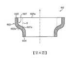
第2圖,為第1圖所示之煞車碟盤單元100的II–II剖面圖。在第2圖中,僅顯示安裝於被安裝構件20之兩面的煞車碟盤10的其中一個,另一個則省略。Figure 2 is a II-II cross-sectional view of the
參考第2圖,煞車碟盤10具有表面101及背面102。表面101,是在煞車碟盤單元100的厚度方向上朝向外側的面。表面101,是可供煞車襯(圖示省略)壓附的滑動面。背面102,面向被安裝構件20的側面。在煞車碟盤10具有延伸於徑向的複數個縱鰭片的場合中,背面102是縱鰭片的頂面。Referring to FIG. 2, the
煞車碟盤單元100的厚度方向,是煞車碟盤10及被安裝構件20的堆疊(積層)方向,煞車碟盤10及被安裝構件20的各厚度方向形成一致。以下,有時將煞車碟盤單元100、煞車碟盤10或者被安裝構件20的厚度方向,單純地稱為厚度方向。此外,有時將煞車碟盤單元100、煞車碟盤10或者被安裝構件20的徑向,單純地稱為徑向。The thickness direction of the
煞車碟盤10含有複數個連結孔103。複數個連結孔103,沿著煞車碟盤10的周方向,保持間隔地配置。連結孔103,分別是朝厚度方向貫穿煞車碟盤10的貫穿孔。The
各連結孔103,含有大徑部1031、小徑部1032。大徑部1031的直徑,大於小徑部1032的直徑。大徑部1031及小徑部1032,依序從煞車碟盤10的表面101朝向背面102配置。大徑部1031朝表面101形成開口。小徑部1032朝背面102形成開口。Each connecting
被安裝構件20含有複數個連結孔203。複數個連結孔203,對應於煞車碟盤10的複數個連結孔103,形成於被安裝構件20。煞車碟盤10,安裝於被安裝構件20的兩面。因此形成:在厚度方向中,其中一個煞車碟盤10的連結孔103、被安裝構件20的連結孔203、另一個煞車碟盤的連結孔(圖示省略)依序排列。The mounted
安裝構造30,是用來將煞車碟盤10安裝於被安裝構件20的構造。安裝構造30,設於煞車碟盤10的各個連結孔103。安裝構造30,具備連結構件301、彈性構件302。The mounting
連結構件301,將煞車碟盤10連結於被安裝構件20。連結構件301,插入煞車碟盤10的連結孔103、及被安裝構件20的連結孔203。連結構件301,具有螺帽3011、螺栓3012。The connecting
螺帽3011,收容於煞車碟盤10的連結孔103內。更詳細地說,螺帽3011,配置於連結孔103的大徑部1031內。The
螺栓3012包含軸部3012a。軸部3012a,從螺帽3011延伸至被安裝構件20側。軸部3012a,朝厚度方向貫穿煞車碟盤10及被安裝構件20而延伸。The
軸部3012a,插入煞車碟盤10的連結孔103、及被安裝構件20的連結孔203。更詳細地說,軸部3012a,插入該煞車碟盤10的連結孔103、被安裝構件20的連結孔203、及另一個煞車碟盤的連結孔(圖示省略)。The
在軸部3012a的其中一個端部,安裝有螺帽3011。螺栓3012,在軸部3012a的另一端部具有頭部(圖示省略)。軸部3012a,至少在螺帽3011側的端部具有螺紋部。螺帽3011,具有與軸部3012a的螺紋部對應的螺紋部。軸部3012a的螺紋部,與螺帽3011的螺紋部嵌合。A
彈性構件302,配置於連結構件301的螺帽3011與煞車碟盤10之間。彈性構件302,配置成重疊於煞車碟盤10的連結孔103。在本實施形態中,彈性構件302收容於連結孔103內。The
彈性構件302,具有頂面3021、底面3022、外周面3023。頂面3021,面向連結構件301之螺帽3011的承受面。底面3022,面向連結孔103之大徑部1031的底面。外周面3023,面向大徑部1031的內壁面。外周面3023,連接頂面3021的外周緣、與底面3022的外周緣。The
彈性構件302,具有構件本體3024;及從構件本體3024朝外側突出的凸緣3025、3026。The
構件本體3024形成筒狀。在構件本體3024,插入有連結構件301的軸部3012a。The
凸緣3025設於:構件本體3024的兩端部中,連結構件301之螺帽3011側的端部。凸緣3025,從構件本體3024朝外側延伸。凸緣3025,隨著朝向彈性構件302的外周側,而接近螺帽3011的承受面。凸緣3025,接觸螺帽3011之承受面的外周部。The
凸緣3026設於:構件本體3024的兩端部中,凸緣3025之相反側的端部。凸緣3026,從構件本體3024延伸至彈性構件302的外周側。凸緣3026,隨著朝向彈性構件302的外周側,而接近連結孔103之大徑部1031的底面。凸緣3026,接觸大徑部1031之底面的外周部。The
以下,參考第3圖及第4圖,更詳細地說明彈性構件302。Hereinafter, with reference to FIGS. 3 and 4, the
第3圖,是彈性構件302的立體圖。第4圖,是在包含中心軸X的平面,將彈性構件302切斷的剖面圖。以下,彈性構件302中,將「以包含中心軸X的平面所切斷的剖面」稱為縱剖面,將「以正交於中心軸X的平面所切斷的剖面」稱為橫剖面。此外,彈性構件302中,將「中心軸X延伸的方向」稱為軸方向,將「與中心軸X正交的方向」稱為徑向或者橫方向,將頂面3021側稱為上,將底面3022側稱為下。FIG. 3 is a perspective view of the
參考第3圖及第4圖,彈性構件302,譬如形成略圓筒狀。在本實施形態中,彈性構件302的外徑,從軸方向的兩端部朝向中央部逐漸變小。亦即,如第4圖所示,彈性構件302,在軸方向的兩端部具有最大外徑ODa,在軸方向的中央部具有最小外徑ODb。彈性構件302具有:在整個軸方向上實質且恆定的內徑ID。Referring to FIGS. 3 and 4, the
彈性構件302的最大外徑ODa,為連結構件301的螺帽3011(第2圖)之承受面的直徑以下。在螺帽3011的承受面形狀為非圓形的場合中,彈性構件302的最大外徑ODa,為螺帽3011之承受面的跨距長度(span length)以下。所謂螺帽3011之承受面的跨距長度,是指螺帽3011之承受面的最大尺寸。在彈性構件302的形狀為多角筒狀的場合中,將彈性構件302之橫方向的最大尺寸,設為螺帽3011之承受面的直徑或者跨距長度以下。The maximum outer diameter ODa of the
在彈性構件302中,構件本體3024及凸緣3025、3026形成一體。在第4圖中,以兩點鏈線B表示構件本體3024與凸緣3025、3026之間的邊界。彈性構件302之中,被兩點鏈線B所圍繞的圓筒部分為構件本體3024,朝該圓筒部分的外側突出部分,為凸緣3025、3026。構件本體3024具有:在整個軸方向上實質且恆定的外徑ODb及內徑ID。凸緣3025、3026分別成為略圓環狀,且具有外徑ODa。In the
凸緣3025,連接於構件本體3024的上部。凸緣3025,在彈性構件302的徑向上,朝構件本體3024的外側突出,並略朝上方延伸。凸緣3025的頂面3025a,與構件本體3024的頂面3024a一起構成彈性構件302的頂面3021。構件本體3024的頂面3024a,在彈性構件302的徑向上,朝向外側逐漸上升。凸緣3025的頂面3025a,連接於構件本體3024的頂面3024a,在彈性構件302的徑向上,朝向外側逐漸上升。亦即,彈性構件302的頂面3021,是從徑向的內側朝向外側緩緩上升傾斜的錐面。然而,頂面3021的形狀並不侷限於此。在頂面3021中,徑向的外側部分較內側部分位於更上方即可,舉例來說,亦可在徑向的外側部分(外周部分)設有朝上方突出的凸部。The
凸緣3026,連接於構件本體3024的下部。凸緣3026,在彈性構件302的徑向上,朝構件本體3024的外側突出,並略朝下方延伸。凸緣3026的底面3026b,與構件本體3024的底面3024b一起構成彈性構件302的底面3022。構件本體3024的底面3024b,在彈性構件302的徑向上,朝向外側逐漸下降。凸緣3026的底面3026b,連接於構件本體3024的底面3024b,在彈性構件302的徑向上,朝向外側逐漸下降。亦即,彈性構件302的底面3022,是從徑向的內側朝向外側緩緩下降傾斜的錐面。然而,底面3022的形狀並不侷限於此。在底面3022中,徑向的外側部分較內側部分位於更下方即可,舉例來說,亦可在徑向的外側部分(外周部分)設有朝下方突出的凸部。The
彈性構件302的外周面3023,在彈性構件302的縱剖面視角中,包含曲線部3023a、3023b。曲線部3023a,配置於外周面3023的上部。曲線部3023a,將構件本體3024與上側的凸緣3025予以平順地連接。曲線部3023b,配置於外周面3023的下部。曲線部3023b,將構件本體3024與下側的凸緣3026予以平順地連接。The outer
在本實施形態中,外周面3023,在彈性構件302的縱剖面視角中,僅由具有相同曲率半徑的曲線部3023a、3023b所構成。亦即,外周面3023,整體是在彈性構件302的徑向上朝內側凹陷的單一圓弧面。但是,外周面3023,並不一定要僅由曲線部3023a、3023b所構成,亦可在彈性構件302的縱剖面視角中,含有直線部。此外,曲線部3023a、3023b的曲率半徑,亦可彼此不同。雖然曲線部3023a、3023b,分別如本實施形態所揭示,為單一的圓弧即可,但亦可由具有不同曲率半徑的複數個圓弧所構成。In this embodiment, the outer
凸緣3025、3026,分別具有凸緣寬度Wa、Wb。凸緣寬度Wa,是凸緣3025之外周緣部的軸方向尺寸。凸緣寬度Wb,是凸緣3026之外周緣部的軸方向尺寸。雖然凸緣寬度Wa、Wb,是取決於煞車碟盤單元100 (第2圖)的使用條件等,舉例來說,可以設為2mm~4mm。The
凸緣3025、3026,具有凸緣高度H。在本實施形態中,凸緣3025、3026雖具有相同的凸緣高度H,但亦可具有彼此不同的凸緣高度。凸緣高度H,是凸緣3025、3026朝構件本體3024的外側突出的高度,是彈性構件302的徑向中,凸緣3025、3026的最大尺寸。雖然凸緣高度H,是取決於煞車碟盤單元100(第2圖)的使用條件等,但最好是5mm以下。藉由將凸緣高度H設為5mm以下,能確實地使產生於連結構件301(第2圖)的應力下降。凸緣高度H,為避免彈性構件302的彈簧常數變大,最好為1mm以下。The
構件本體3024的材料厚度,亦即外徑ODb與內徑ID之間的差,譬如可設為5mm~15mm。此外,譬如可將彈性構件302之軸方向的最大長度La設為6mm~20mm,將最小長度Lb設為2mm~16mm。The material thickness of the
[效果]本實施形態的煞車碟盤單元100,將彈性構件302配置於連結構件301的螺帽3011與煞車碟盤10之間。當煞車碟盤10的熱變形所衍生的壓縮荷重已作用於該彈性構件302時,在彈性構件302中,凸緣3025、3026朝軸方向的中央側形成撓曲,而吸收「連結構件301伴隨著煞車碟盤10的變形所產生的變形」。據此,能降低對連結構件301的負荷,可提高連結構件301的疲勞強度。[effect]In the
彈性構件302,以凸緣3025接觸連結構件301之螺帽3011的外周部。彈性構件302,並未接觸螺帽3011的內周部。因此,在連結構件301中,螺帽3011與螺栓3012的軸部3012a之間的連接部不被彈性構件302所拘束,容許螺帽3011及軸部3012a的變形。據此,產生於連結構件301的應力得以緩和,能降低對連結構件301的負荷。The
本實施形態的安裝構造30,是應用於:在表面(滑動面)101的中央設有連結部的中央連結型的煞車碟盤10。在中央連結型的煞車碟盤10中,連結構件301的螺帽3011及彈性構件302收容於連結孔103的大徑部1031內。因此,彈性構件302的最大外徑ODa,必然成為螺帽3011之承受面的直徑或者跨距長度以下。如此一來,在外徑具有限制的場合中,一般的碟型彈簧,由於難以實現低彈簧常數,因此,有時無法令「對連結構件301的負荷」充分地下降。相對於此,本實施形態的彈性構件302,由於在軸方向的兩端部具有凸緣3025、3026,相較於具有相同外徑的一般碟型彈簧,變形量更大,能具有低彈簧常數。據此,即使在「對彈性構件302的外徑產生限制」之中央連結型的煞車碟盤10中,也能使「對連結構件301的負荷」充分地降低。The
在中央連結型的煞車碟盤10中,由於連結構件301收容於連結孔103,因此連結構件301的尺寸存在限制,難以提高連結構件301本身的強度。此外,在中央連結型的煞車碟盤10中,由於連結孔103配置於具有熱輸入量的表面(滑動面)101,因此具有:因煞車碟盤10的熱變形而加大對連結構件301之負荷的傾向。因此,本實施形態的安裝構造30,特別適用於中央連結型的煞車碟盤10。亦即,根據安裝構造30,由於可藉由凸緣3025、3026的撓曲使彈性構件302大幅變形,故能吸收煞車碟盤10的熱變形,可防止對連結構件301的負荷增大。然而,也能將安裝構造30應用於中央連結型以外的煞車碟盤。In the
在本實施形態中,在彈性構件302之軸方向的兩端部,分別設有凸緣3025、3026。亦即,彈性構件302實質上形成上下對稱。因此,當組裝煞車碟盤單元100時,操作者無須在意彈性構件302的上下,能提高作業性。In this embodiment,
在本實施形態中,彈性構件302,在縱剖面視角中,於外周面3023含有曲線部3023a、3023b。曲線部3023a、3023b,將凸緣3025、3026與構件本體3024予以平順地連接。據此,當凸緣3025、3026因壓縮荷重而形成撓曲時,能抑制在凸緣3025、3026的基部發生應力集中的情形,可防止凸緣3025、3026的破損。In this embodiment, the
<第2實施形態>接著,說明本發明的第2實施形態。第5圖,為顯示第2實施形態的煞車碟盤單元200之安裝構造40的剖面圖。第6圖,為安裝構造40所含有之彈性構件402的縱剖面圖。第2實施形態的煞車碟盤單元200,安裝構造40之彈性構件402的形狀,與第1實施形態的煞車碟盤單元100(第2圖)不同。<The second embodiment>Next, the second embodiment of the present invention will be described. Fig. 5 is a cross-sectional view showing the mounting
如第5圖所示,彈性構件402,與第1實施形態相同,含有頂面4021、底面4022、外周面4023。彈性構件402,與第1實施形態相同,具有筒狀的構件本體4024、頂面4021側的凸緣4025。彈性構件402,不同於第1實施形態,在底面4022側不具有凸緣。As shown in FIG. 5, the
凸緣4025設於:構件本體4024的兩端部中,連結構件301之螺帽3011側的端部。凸緣4025,從構件本體4024延伸至彈性構件402的外周側且螺帽3011側,接觸螺帽3011之承受面的外周部。The
參考第6圖,彈性構件402之上部的凸緣4025,具有與第1實施形態之凸緣3025(第3圖及第4圖)相同的構造。凸緣4025,在彈性構件402的徑向上,朝構件本體4024的外側突出。凸緣4025的頂面4025a,與構件本體4024的頂面4024a一起構成錐狀的頂面4021。另外,由於在彈性構件402的下部並不存在凸緣,因此彈性構件402的底面4022,僅由構件本體4024的底面所構成。底面4022,是大致平行於彈性構件402之徑向的環狀面。Referring to Fig. 6, the
外周面4023,在彈性構件402的縱剖面視角中,含有曲線部4023a、直線部4023c。曲線部4023a,配置於外周面4023的上部。曲線部4023a,將構件本體4024與凸緣4025予以平順地連接。雖然曲線部4023a為單一的圓弧即可,但亦可由具有不同曲率半徑的複數個圓弧所構成。直線部4023c,沿著彈性構件402的軸方向,從曲線部4023a朝向底面4022筆直地延伸。The outer
如此一來,在本實施形態中,在彈性構件402之軸方向的兩端部中,僅於其中一個設有凸緣4025。據此,當煞車碟盤10變形而對彈性構件402作用壓縮荷重時,凸緣4025朝軸方向的中央側形成撓曲,而吸收煞車碟盤10的變形。因此,能降低對連結構件301的負荷。In this way, in this embodiment, only one of the two ends of the
彈性構件402,以凸緣4025接觸連結構件301之螺帽3011的外周部,並未接觸螺帽3011的內周部。彈性構件402不會對螺帽3011與螺栓3012的軸部3012a之間的連接部形成拘束,容許螺帽3011及軸部3012a的變形。據此,可緩和產生於連結構件301的應力,能降低對連結構件301的負荷。The
如此一來,即使在本實施形態中,也與第1實施形態相同,能降低對連結構件301的負荷,可提高連結構件301的疲勞強度。In this way, even in this embodiment, as in the first embodiment, the load on the connecting
以上,雖然說明了本發明實施形態,但本發明並不侷限於上述實施形態,在不脫離本發明要旨的範圍內,能有各式各樣的變更。Although the embodiments of the present invention have been described above, the present invention is not limited to the above-mentioned embodiments, and various modifications can be made without departing from the gist of the present invention.
舉例來說,在上述的第1實施形態中,彈性構件302具有:在整個軸方向上實質且恆定的內徑ID。然而,彈性構件302的內徑ID,也可以為非恆定。For example, in the first embodiment described above, the elasticityThe
第7圖,是第1實施形態的彈性構件302(第4圖)之變形例的彈性構件502的縱剖面圖。如第7圖所示,彈性構件502的內徑及外徑,從軸方向的兩端部朝向中央部逐漸變小。亦即,彈性構件502,在軸方向的兩端部具有最大內徑IDa,在軸方向的中央部具有最小內徑IDb。此外,彈性構件502,與第1實施形態中的彈性構件302相同,在軸方向的兩端部具有最大外徑ODa,在軸方向的中央部具有最小外徑ODb。Fig. 7 is a longitudinal sectional view of an
在彈性構件502中,其中一個凸緣5025,從構件本體5024朝向外側且上方延伸。因此,凸緣5025的頂面5025a,在第2圖所示的煞車碟盤單元100中,接觸螺帽3011之承受面的外周部。在第7圖所示的例子中,頂面5025a,是實質地平行於彈性構件502的徑向。但是,頂面5025a亦可與第1實施形態相同,在彈性構件502的徑向上,朝向外側逐漸上升地形成傾斜。In the
另一個凸緣5026,從構件本體5024朝向外側且下方延伸。因此,凸緣5026的底面5026b,在第2圖所示的煞車碟盤單元100中,接觸連結孔103的大徑部1031之底面的外周部。在第7圖所示的例子中,底面5026b,是實質地平行於彈性構件502的徑向。但是,底面5026b亦可與第1實施形態相同,在彈性構件502的徑向上,朝向外側逐漸下降地形成傾斜。The
構件本體5024與凸緣5025、5026,是藉由分別設於彈性構件502的外周面5023及內周面5027的曲線部5023a、5027a而平順地連接。The
此外,譬如在上述各實施形態中,彈性構件302、402的凸緣3025、4025,從構件本體3024、4024朝向外側延伸。但是,凸緣3025、4025,只要能從構件本體3024、4024突出並接觸螺帽3011的外周部即可,並不侷限於上述各實施形態所說明的樣態。In addition, for example, in each of the above-mentioned embodiments, the
第8圖,是第2實施形態的彈性構件402(第6圖)之變形例的彈性構件602的縱剖面圖。如第8圖所示,在彈性構件602中,凸緣6025,從構件本體6024朝向外側突出。凸緣6025,大致朝構件本體6024的軸方向延伸。凸緣6025,由於在彈性構件602的徑向上較構件本體6024更配置於外側,因此在第2圖所示的煞車碟盤單元100中,接觸螺帽3011之承受面的外周部。在第8圖所示的例子中,凸緣6025的頂面6025a,是實質地平行於彈性構件602的徑向。但是,頂面6025a亦可與第2實施形態相同,在彈性構件602的徑向上,朝向外側逐漸上升地形成傾斜。構件本體6024與凸緣6025,是藉由分別設於彈性構件602的外周面6023及內周面6027的曲線部6023a、6027a而平順地連接。Fig. 8 is a longitudinal sectional view of an
在上述各實施形態的煞車碟盤單元100、200中,可將彈性構件302、402、502、602的其中任一個配置在:相對於被安裝構件20,安裝於第2圖及第5圖所示之煞車碟盤10的相反側的煞車碟盤(圖示省略)、與螺栓3012的頭部(圖示省略)之間。彈性構件402或者彈性構件602,可將凸緣4025、6025配置成朝向螺栓3012的頭部,也可以將凸緣4025、6025配置成朝向煞車碟盤側。亦即,彈性構件402或者彈性構件602,也能以底面接觸螺栓3012的頭部之承受面的內周面。在煞車碟盤、與螺栓3012的頭部之間,亦可配置一般的碟型彈簧,而非彈性構件302、402、502、602。[實施例]In the
以下,藉由實施例,更詳細地說明本發明。但是,本發明並不侷限於以下的實施例。The following examples illustrate the present invention in more detail. However, the present invention is not limited to the following examples.
製作具有「新幹線用中央連結型的煞車碟盤」、與「將該煞車碟盤安裝於被安裝構件的安裝構造」的模型,並執行了基於有限元素法(finite element method)的分析(FEM分析)。該模型的煞車碟盤,具備與第2圖所示之煞車碟盤單元100相同的構造。A model with a "central connection type brake disc for the Shinkansen" and an "installation structure for installing the brake disc on the component to be installed" was produced, and analysis based on the finite element method (FEM analysis) was performed. ). The brake disc of this model has the same structure as the
在FEM分析中,是假設「鐵道車輛以360km/h行駛時,實施停止煞車」的場合,而算出發生於連結構件301的最大應力。FEM分析,藉由將彈性構件302的凸緣寬度Wa、Wb設為恆定,並將凸緣高度H變更為2.3mm、2.9mm、4.8mm,而算出各凸緣高度H的最大應力。In the FEM analysis, it is assumed that the “stop braking is applied when the railway vehicle is running at 360 km/h”, and the maximum stress that occurs in the connecting
第9圖,是顯示凸緣高度H、與發生於連結構件301的最大應力間之關係的圖表。在第9圖的圖表中,以虛線表示「使用碟型彈簧取代彈性構件302時的最大應力」。Fig. 9 is a graph showing the relationship between the flange height H and the maximum stress occurring in the connecting
如第9圖所示,倘若在「將煞車碟盤10安裝於被安裝構件20的安裝構造30」中使用「具有凸緣3025、3026的彈性構件302」,相較於使用碟型彈簧的場合,發生於連結構件301的最大應力變小。換言之,可得知能藉由彈性構件302降低對連結構件301的負荷。As shown in Figure 9, if the "
根據本實施例可得知:只要凸緣高度H為5mm以下,發生於連結構件301的最大應力,較使用碟型彈簧時更小。據此,為了確實地降低對連結構件301的負荷,最好是將凸緣高度H設為5mm以下。而根據所謂實現低彈簧常數的觀點,凸緣高度H最好為1mm以上。According to this embodiment, it can be known that as long as the flange height H is less than 5 mm, the maximum stress occurring in the connecting
100,200:煞車碟盤單元10:煞車碟盤20:被安裝構件30,40:安裝構造301:連結構件3011:螺帽3012:螺栓3012a:軸部302,402,502,602:彈性構件3023,4023:外周面3023a,3023b,4023a,5023a,6023a:曲線部3024,4024,5024,6024:構件本體3025,3026,4025,5025,5026,6025:凸緣100,200: brake disc unit10: Brake disc20: Installed
[第1圖]:第1圖為第1實施形態之煞車碟盤單元的俯視圖。[第2圖]:第2圖為第1圖所示之煞車碟盤單元的II–II剖面圖。[第3圖]:第3圖為第1圖顯示的煞車碟盤單元所含有之彈性構件的立體圖。[第4圖]:第4圖為第3圖所示之彈性構件的縱剖面圖。[第5圖]:第5圖為顯示第2實施形態的煞車碟盤單元之局部的剖面圖。[第6圖]:第6圖為第5圖顯示的煞車碟盤單元所含有之彈性構件的縱剖面圖。[第7圖]:第7圖為第3圖及第4圖所示的彈性構件之變形例的縱剖面圖。[第8圖]:第8圖為第6圖所示的彈性構件之變形例的縱剖面圖。[第9圖]:第9圖是顯示實施例之彈性構件的凸緣高度、與發生於連結構件的最大應力間之關係的圖表。[Figure 1]: Figure 1 is a plan view of the brake disc unit of the first embodiment.[Figure 2]: Figure 2 is the II-II cross-sectional view of the brake disc unit shown in Figure 1.[Figure 3]: Figure 3 is a perspective view of the elastic member contained in the brake disc unit shown in Figure 1.[Figure 4]: Figure 4 is a longitudinal cross-sectional view of the elastic member shown in Figure 3.[Figure 5] Figure 5 is a cross-sectional view showing a part of the brake disc unit of the second embodiment.[Figure 6]: Figure 6 is a longitudinal sectional view of the elastic member contained in the brake disc unit shown in Figure 5.[Fig. 7]: Fig. 7 is a longitudinal sectional view of a modification of the elastic member shown in Figs. 3 and 4.[Fig. 8]: Fig. 8 is a longitudinal sectional view of a modification of the elastic member shown in Fig. 6.[Figure 9]: Figure 9 is a graph showing the relationship between the flange height of the elastic member of the embodiment and the maximum stress occurring in the connecting member.
10:煞車碟盤10: Brake disc
20:被安裝構件20: Installed components
30:安裝構造30: Installation structure
100:煞車碟盤單元100: Brake disc unit
101:表面101: Surface
102:背面102: back
103:連結孔103: connecting hole
203:連結孔203: link hole
301:連結構件301: Connecting member
302:彈性構件302: Elastic member
1031:大徑部1031: Large diameter part
1032:小徑部1032: Small diameter part
3011:螺帽3011: Nut
3012:螺栓3012: Bolt
3012a:軸部3012a: Shaft
3021:頂面3021: top surface
3022:底面3022: Bottom
3023:外周面3023: outer peripheral surface
3024:構件本體3024: component body
3025,3026:凸緣3025, 3026: flange
Claims (5)
Translated fromChineseApplications Claiming Priority (2)
| Application Number | Priority Date | Filing Date | Title |
|---|---|---|---|
| JP2018188016 | 2018-10-03 | ||
| JP2018-188016 | 2018-10-03 |
Publications (2)
| Publication Number | Publication Date |
|---|---|
| TW202024502A TW202024502A (en) | 2020-07-01 |
| TWI727445Btrue TWI727445B (en) | 2021-05-11 |
Family
ID=70055168
Family Applications (1)
| Application Number | Title | Priority Date | Filing Date |
|---|---|---|---|
| TW108135822ATWI727445B (en) | 2018-10-03 | 2019-10-03 | Installation structure of brake disc for railway vehicle and brake disc unit using the installation structure |
Country Status (5)
| Country | Link |
|---|---|
| US (1) | US20210396287A1 (en) |
| JP (1) | JP7156384B2 (en) |
| CN (1) | CN112789427B (en) |
| TW (1) | TWI727445B (en) |
| WO (1) | WO2020071347A1 (en) |
Families Citing this family (3)
| Publication number | Priority date | Publication date | Assignee | Title |
|---|---|---|---|---|
| EP3803723A4 (en) | 2018-06-01 | 2022-03-09 | Stress Engineering Services, Inc. | SYSTEMS AND PROCEDURES FOR MONITORING, TRACKING AND TRACEBACK OF LOGISTICS |
| CN113638989A (en)* | 2021-07-27 | 2021-11-12 | 镇江市营房塑电有限公司 | Fasteners for breathing dust filters and breathing dust filters |
| US11773626B2 (en) | 2022-02-15 | 2023-10-03 | Stress Engineering Services, Inc. | Systems and methods for facilitating logistics |
Citations (3)
| Publication number | Priority date | Publication date | Assignee | Title |
|---|---|---|---|---|
| CN1668481A (en)* | 2002-07-17 | 2005-09-14 | 庞巴迪运输公司 | Reduction of torsional vibrations in rail vehicle wheelsets |
| JP2008121774A (en)* | 2006-11-10 | 2008-05-29 | Jtekt Corp | Rolling bearing device for wheels |
| JP2014190344A (en)* | 2013-03-26 | 2014-10-06 | Nippon Steel & Sumitomo Metal | Disc spring insertion jig for railroad wheel with brake disc and assembling method |
Family Cites Families (32)
| Publication number | Priority date | Publication date | Assignee | Title |
|---|---|---|---|---|
| US1057686A (en)* | 1911-08-17 | 1913-04-01 | 100 Rail Joint Company | Washer. |
| US1183174A (en)* | 1916-01-05 | 1916-05-16 | William M Dice | Locking-washer for nuts. |
| US1504511A (en)* | 1921-12-09 | 1924-08-12 | Samuel E Ross | Nut lock |
| US1567649A (en)* | 1922-06-07 | 1925-12-29 | Skf Svenska Kullagerfab Ab | Nut lock |
| US1648347A (en)* | 1926-11-10 | 1927-11-08 | Shakeproof Lock Washer Co | Cylindrical lock washer |
| US2766799A (en)* | 1955-05-04 | 1956-10-16 | Illinois Tool Works | Resilient split ring lock washer having substantially u-shaped cross section |
| US2923340A (en)* | 1957-09-10 | 1960-02-02 | Safety Socket Screw Company | Threaded fastener means including malleable withdrawable lock washer |
| US3002544A (en)* | 1958-06-20 | 1961-10-03 | Philadelphia Steel And Wire Co | Rib lock washer |
| US3134585A (en)* | 1960-02-08 | 1964-05-26 | Miner Inc W H | Shock attenuating devices |
| US3202412A (en)* | 1964-03-06 | 1965-08-24 | Miner Inc W H | Shock attenuating devices |
| CH418063A (en)* | 1964-04-11 | 1966-07-31 | Gomma Antivibranti Applic | Rubber springs or similar elastic material |
| US3279779A (en)* | 1964-07-20 | 1966-10-18 | Lord Corp | Combined disc and elastomeric spring |
| US3416783A (en)* | 1965-11-19 | 1968-12-17 | Firgat S N C | Rubber-metal spring device |
| US3489402A (en)* | 1966-08-22 | 1970-01-13 | Btr Industries Ltd | Composite elastomeric springs |
| US3426819A (en)* | 1967-02-20 | 1969-02-11 | Federal Screw Works | Bolt with deformable washer |
| US4073858A (en)* | 1975-04-07 | 1978-02-14 | The Goodyear Tire & Rubber Company | Shock absorbing unit molded from polyurethane (urea) rubber composition |
| US4006803A (en)* | 1975-07-11 | 1977-02-08 | Bergische Stahl-Industrie | Wheel with brake discs for rail vehicles |
| JPS52117762U (en)* | 1976-03-05 | 1977-09-07 | ||
| JPS52117762A (en)* | 1976-03-23 | 1977-10-03 | Kaneko Agricult Machinery | Dischabging device in unhusked rice dryer |
| US4102443A (en)* | 1977-08-22 | 1978-07-25 | Abex Corporation | Disc mounting ring |
| US4364615A (en)* | 1980-09-08 | 1982-12-21 | The Bendix Corporation | Retaining ring |
| US4958970A (en)* | 1988-08-17 | 1990-09-25 | The United States Of America As Represented By The Secretary Of The Navy | Graduated-load spring washer system for screws and threaded fasteners |
| JPH0968213A (en)* | 1995-08-29 | 1997-03-11 | Shinohara Denki Kk | Article mounting device |
| US5957441A (en)* | 1997-09-05 | 1999-09-28 | Miner Enterprises, Inc. | Hourglass-shaped elastomeric compression spring |
| JP2001187911A (en)* | 1999-12-28 | 2001-07-10 | Fukasawa:Kk | Screw fastening structure |
| JP4638248B2 (en)* | 2005-01-25 | 2011-02-23 | ナブテスコ株式会社 | Disc pad |
| US7490819B2 (en)* | 2006-02-01 | 2009-02-17 | Miner Elastomer Products Corporation | X-shaped elastomeric spring |
| JP4748390B2 (en)* | 2006-02-20 | 2011-08-17 | 住友金属工業株式会社 | Rotating body fastening structure and railway vehicle axle using the same |
| JP5503537B2 (en)* | 2008-06-26 | 2014-05-28 | 株式会社フコク | Bump stopper and manufacturing method thereof |
| EP2360386B2 (en)* | 2008-12-19 | 2017-06-14 | Nippon Steel & Sumitomo Metal Corporation | Brake disc for railroad vehicle |
| US20140248146A1 (en)* | 2012-08-31 | 2014-09-04 | United Technologies Corporation | Attachment apparatus for ceramic matrix composite materials |
| JP6939684B2 (en)* | 2018-04-12 | 2021-09-22 | トヨタ自動車株式会社 | Tire wheel, brake rotor and hub assembly structure |
- 2019
- 2019-10-01JPJP2020550441Apatent/JP7156384B2/enactiveActive
- 2019-10-01CNCN201980065034.XApatent/CN112789427B/enactiveActive
- 2019-10-01WOPCT/JP2019/038695patent/WO2020071347A1/ennot_activeCeased
- 2019-10-01USUS17/281,704patent/US20210396287A1/enactivePending
- 2019-10-03TWTW108135822Apatent/TWI727445B/enactive
Patent Citations (3)
| Publication number | Priority date | Publication date | Assignee | Title |
|---|---|---|---|---|
| CN1668481A (en)* | 2002-07-17 | 2005-09-14 | 庞巴迪运输公司 | Reduction of torsional vibrations in rail vehicle wheelsets |
| JP2008121774A (en)* | 2006-11-10 | 2008-05-29 | Jtekt Corp | Rolling bearing device for wheels |
| JP2014190344A (en)* | 2013-03-26 | 2014-10-06 | Nippon Steel & Sumitomo Metal | Disc spring insertion jig for railroad wheel with brake disc and assembling method |
Also Published As
| Publication number | Publication date |
|---|---|
| CN112789427B (en) | 2023-03-17 |
| JPWO2020071347A1 (en) | 2021-09-02 |
| JP7156384B2 (en) | 2022-10-19 |
| US20210396287A1 (en) | 2021-12-23 |
| CN112789427A (en) | 2021-05-11 |
| TW202024502A (en) | 2020-07-01 |
| WO2020071347A1 (en) | 2020-04-09 |
Similar Documents
| Publication | Publication Date | Title |
|---|---|---|
| TWI727445B (en) | Installation structure of brake disc for railway vehicle and brake disc unit using the installation structure | |
| KR101427501B1 (en) | Rail car brake lining | |
| US8398178B2 (en) | Vehicle wheel disk | |
| US7918322B2 (en) | System for connecting a brake disc and hub | |
| US7077247B2 (en) | Brake rotor attachment assembly that promotes in plane uniform torque transfer distribution | |
| US20150247541A1 (en) | Railway vehicle brake disc | |
| JP2007315541A (en) | Opposed piston type disk brake | |
| US8967341B2 (en) | Wheel-mounted brake disks | |
| CN106687303A (en) | Wheel with rim and disc | |
| US11162550B2 (en) | Caliper for opposed piston type disc brake | |
| KR20140052616A (en) | Brake disk for vehicle | |
| US8881877B2 (en) | Vibration damper | |
| JP4305296B2 (en) | Brake discs for railway vehicles | |
| JP6794451B2 (en) | Brake rotor for vehicles | |
| JP2009068593A (en) | Opposed piston type disc brake | |
| KR101440143B1 (en) | A railway wheel formed of two different material parts | |
| US11535054B2 (en) | Track wheel and elastic body for such a track wheel | |
| CN209757266U (en) | Sub vehicle frame connection structure and vehicle | |
| US20110097027A1 (en) | Outer ring for wheel bearing | |
| JP4785516B2 (en) | Railway vehicle brake linings and disc brakes | |
| JP7047917B2 (en) | Brake disc mounting structure for railway vehicles and brake disc units using this | |
| JP7478125B2 (en) | Floating type brake disc and wheel for saddle-type vehicle | |
| CN119878740A (en) | Rubber support | |
| JP2015189285A (en) | Wheel installing structure |