TWI725072B - Etching method - Google Patents
Etching methodDownload PDFInfo
- Publication number
- TWI725072B TWI725072BTW105137210ATW105137210ATWI725072BTW I725072 BTWI725072 BTW I725072BTW 105137210 ATW105137210 ATW 105137210ATW 105137210 ATW105137210 ATW 105137210ATW I725072 BTWI725072 BTW I725072B
- Authority
- TW
- Taiwan
- Prior art keywords
- gas
- etching
- sif
- mask
- film
- Prior art date
Links
- 238000005530etchingMethods0.000titleclaimsabstractdescription126
- 238000000034methodMethods0.000titleclaimsabstractdescription64
- NBVXSUQYWXRMNV-UHFFFAOYSA-NfluoromethaneChemical compoundFCNBVXSUQYWXRMNV-UHFFFAOYSA-N0.000claimsabstractdescription14
- ABTOQLMXBSRXSM-UHFFFAOYSA-Nsilicon tetrafluorideChemical compoundF[Si](F)(F)FABTOQLMXBSRXSM-UHFFFAOYSA-N0.000claimsabstractdescription7
- 239000007789gasSubstances0.000claimsdescription143
- VYPSYNLAJGMNEJ-UHFFFAOYSA-NSilicium dioxideChemical compoundO=[Si]=OVYPSYNLAJGMNEJ-UHFFFAOYSA-N0.000claimsdescription25
- 229910052814silicon oxideInorganic materials0.000claimsdescription25
- 229910052760oxygenInorganic materials0.000claimsdescription6
- 229910052710siliconInorganic materials0.000claimsdescription6
- 239000010703siliconSubstances0.000claimsdescription6
- QVGXLLKOCUKJST-UHFFFAOYSA-Natomic oxygenChemical compound[O]QVGXLLKOCUKJST-UHFFFAOYSA-N0.000claimsdescription4
- 239000001301oxygenSubstances0.000claimsdescription4
- TXEYQDLBPFQVAA-UHFFFAOYSA-NtetrafluoromethaneChemical compoundFC(F)(F)FTXEYQDLBPFQVAA-UHFFFAOYSA-N0.000claimsdescription3
- 125000004430oxygen atomChemical groupO*0.000claims1
- 230000008569processEffects0.000abstractdescription8
- NRTOMJZYCJJWKI-UHFFFAOYSA-NTitanium nitrideChemical compound[Ti]#NNRTOMJZYCJJWKI-UHFFFAOYSA-N0.000description25
- 239000003507refrigerantSubstances0.000description15
- 238000010586diagramMethods0.000description11
- 229910052581Si3N4Inorganic materials0.000description10
- 229920002120photoresistant polymerPolymers0.000description10
- HQVNEWCFYHHQES-UHFFFAOYSA-Nsilicon nitrideChemical compoundN12[Si]34N5[Si]62N3[Si]51N64HQVNEWCFYHHQES-UHFFFAOYSA-N0.000description10
- OKTJSMMVPCPJKN-UHFFFAOYSA-NCarbonChemical compound[C]OKTJSMMVPCPJKN-UHFFFAOYSA-N0.000description8
- 229910052799carbonInorganic materials0.000description8
- 238000009792diffusion processMethods0.000description7
- 238000009616inductively coupled plasmaMethods0.000description7
- 229910004298SiO 2Inorganic materials0.000description6
- 230000006870functionEffects0.000description6
- 239000010410layerSubstances0.000description6
- 229910021420polycrystalline siliconInorganic materials0.000description6
- 229920005591polysiliconPolymers0.000description6
- XUIMIQQOPSSXEZ-UHFFFAOYSA-NSiliconChemical compound[Si]XUIMIQQOPSSXEZ-UHFFFAOYSA-N0.000description5
- 230000000052comparative effectEffects0.000description5
- 230000009545invasionEffects0.000description5
- 230000002093peripheral effectEffects0.000description5
- 239000004065semiconductorSubstances0.000description5
- 239000000463materialSubstances0.000description4
- 229910052751metalInorganic materials0.000description4
- 239000002184metalSubstances0.000description4
- UGFAIRIUMAVXCW-UHFFFAOYSA-NCarbon monoxideChemical compound[O+]#[C-]UGFAIRIUMAVXCW-UHFFFAOYSA-N0.000description3
- BOTDANWDWHJENH-UHFFFAOYSA-NTetraethyl orthosilicateChemical compoundCCO[Si](OCC)(OCC)OCCBOTDANWDWHJENH-UHFFFAOYSA-N0.000description3
- 230000003667anti-reflective effectEffects0.000description3
- 238000001636atomic emission spectroscopyMethods0.000description3
- 229910002091carbon monoxideInorganic materials0.000description3
- 229910052731fluorineInorganic materials0.000description3
- LIVNPJMFVYWSIS-UHFFFAOYSA-Nsilicon monoxideChemical compound[Si-]#[O+]LIVNPJMFVYWSIS-UHFFFAOYSA-N0.000description3
- XKRFYHLGVUSROY-UHFFFAOYSA-NArgonChemical compound[Ar]XKRFYHLGVUSROY-UHFFFAOYSA-N0.000description2
- CURLTUGMZLYLDI-UHFFFAOYSA-NCarbon dioxideChemical compoundO=C=OCURLTUGMZLYLDI-UHFFFAOYSA-N0.000description2
- PXGOKWXKJXAPGV-UHFFFAOYSA-NFluorineChemical compoundFFPXGOKWXKJXAPGV-UHFFFAOYSA-N0.000description2
- 230000009471actionEffects0.000description2
- 229910052782aluminiumInorganic materials0.000description2
- XAGFODPZIPBFFR-UHFFFAOYSA-NaluminiumChemical compound[Al]XAGFODPZIPBFFR-UHFFFAOYSA-N0.000description2
- 238000006243chemical reactionMethods0.000description2
- 239000011737fluorineSubstances0.000description2
- 239000012212insulatorSubstances0.000description2
- 230000007246mechanismEffects0.000description2
- 238000001020plasma etchingMethods0.000description2
- 239000000758substrateSubstances0.000description2
- 239000010936titaniumSubstances0.000description2
- LGPPATCNSOSOQH-UHFFFAOYSA-N1,1,2,3,4,4-hexafluorobuta-1,3-dieneChemical compoundFC(F)=C(F)C(F)=C(F)FLGPPATCNSOSOQH-UHFFFAOYSA-N0.000description1
- 239000004341OctafluorocyclobutaneSubstances0.000description1
- RTAQQCXQSZGOHL-UHFFFAOYSA-NTitaniumChemical compound[Ti]RTAQQCXQSZGOHL-UHFFFAOYSA-N0.000description1
- 238000002048anodisation reactionMethods0.000description1
- 229910052786argonInorganic materials0.000description1
- 238000001675atomic spectrumMethods0.000description1
- 210000002469basement membraneAnatomy0.000description1
- 238000005452bendingMethods0.000description1
- 239000012267brineSubstances0.000description1
- 229910002092carbon dioxideInorganic materials0.000description1
- 239000001569carbon dioxideSubstances0.000description1
- 230000008094contradictory effectEffects0.000description1
- 239000002826coolantSubstances0.000description1
- 239000000498cooling waterSubstances0.000description1
- 230000008878couplingEffects0.000description1
- 238000010168coupling processMethods0.000description1
- 238000005859coupling reactionMethods0.000description1
- 230000000694effectsEffects0.000description1
- 239000001307heliumSubstances0.000description1
- 229910052734heliumInorganic materials0.000description1
- SWQJXJOGLNCZEY-UHFFFAOYSA-Nhelium atomChemical compound[He]SWQJXJOGLNCZEY-UHFFFAOYSA-N0.000description1
- 239000011229interlayerSubstances0.000description1
- 150000002500ionsChemical class0.000description1
- 239000004973liquid crystal related substanceSubstances0.000description1
- 230000000873masking effectEffects0.000description1
- 239000000203mixtureSubstances0.000description1
- BCCOBQSFUDVTJQ-UHFFFAOYSA-NoctafluorocyclobutaneChemical compoundFC1(F)C(F)(F)C(F)(F)C1(F)FBCCOBQSFUDVTJQ-UHFFFAOYSA-N0.000description1
- 235000019407octafluorocyclobutaneNutrition0.000description1
- TWNQGVIAIRXVLR-UHFFFAOYSA-Noxo(oxoalumanyloxy)alumaneChemical compoundO=[Al]O[Al]=OTWNQGVIAIRXVLR-UHFFFAOYSA-N0.000description1
- 238000009832plasma treatmentMethods0.000description1
- 230000001681protective effectEffects0.000description1
- HBMJWWWQQXIZIP-UHFFFAOYSA-Nsilicon carbideChemical compound[Si+]#[C-]HBMJWWWQQXIZIP-UHFFFAOYSA-N0.000description1
- HPALAKNZSZLMCH-UHFFFAOYSA-Msodium;chloride;hydrateChemical compoundO.[Na+].[Cl-]HPALAKNZSZLMCH-UHFFFAOYSA-M0.000description1
- 238000001228spectrumMethods0.000description1
- 239000000126substanceSubstances0.000description1
- 229910052719titaniumInorganic materials0.000description1
Images


Classifications
- H—ELECTRICITY
- H01—ELECTRIC ELEMENTS
- H01L—SEMICONDUCTOR DEVICES NOT COVERED BY CLASS H10
- H01L21/00—Processes or apparatus adapted for the manufacture or treatment of semiconductor or solid state devices or of parts thereof
- H01L21/02—Manufacture or treatment of semiconductor devices or of parts thereof
- H01L21/04—Manufacture or treatment of semiconductor devices or of parts thereof the devices having potential barriers, e.g. a PN junction, depletion layer or carrier concentration layer
- H01L21/18—Manufacture or treatment of semiconductor devices or of parts thereof the devices having potential barriers, e.g. a PN junction, depletion layer or carrier concentration layer the devices having semiconductor bodies comprising elements of Group IV of the Periodic Table or AIIIBV compounds with or without impurities, e.g. doping materials
- H01L21/30—Treatment of semiconductor bodies using processes or apparatus not provided for in groups H01L21/20 - H01L21/26
- H01L21/302—Treatment of semiconductor bodies using processes or apparatus not provided for in groups H01L21/20 - H01L21/26 to change their surface-physical characteristics or shape, e.g. etching, polishing, cutting
- H01L21/306—Chemical or electrical treatment, e.g. electrolytic etching
- H01L21/3065—Plasma etching; Reactive-ion etching
- H—ELECTRICITY
- H01—ELECTRIC ELEMENTS
- H01J—ELECTRIC DISCHARGE TUBES OR DISCHARGE LAMPS
- H01J37/00—Discharge tubes with provision for introducing objects or material to be exposed to the discharge, e.g. for the purpose of examination or processing thereof
- H01J37/32—Gas-filled discharge tubes
- H01J37/32009—Arrangements for generation of plasma specially adapted for examination or treatment of objects, e.g. plasma sources
- H01J37/32082—Radio frequency generated discharge
- H01J37/32091—Radio frequency generated discharge the radio frequency energy being capacitively coupled to the plasma
- H—ELECTRICITY
- H01—ELECTRIC ELEMENTS
- H01J—ELECTRIC DISCHARGE TUBES OR DISCHARGE LAMPS
- H01J37/00—Discharge tubes with provision for introducing objects or material to be exposed to the discharge, e.g. for the purpose of examination or processing thereof
- H01J37/32—Gas-filled discharge tubes
- H01J37/32009—Arrangements for generation of plasma specially adapted for examination or treatment of objects, e.g. plasma sources
- H—ELECTRICITY
- H01—ELECTRIC ELEMENTS
- H01J—ELECTRIC DISCHARGE TUBES OR DISCHARGE LAMPS
- H01J37/00—Discharge tubes with provision for introducing objects or material to be exposed to the discharge, e.g. for the purpose of examination or processing thereof
- H01J37/32—Gas-filled discharge tubes
- H01J37/32431—Constructional details of the reactor
- H01J37/3244—Gas supply means
- H—ELECTRICITY
- H01—ELECTRIC ELEMENTS
- H01J—ELECTRIC DISCHARGE TUBES OR DISCHARGE LAMPS
- H01J37/00—Discharge tubes with provision for introducing objects or material to be exposed to the discharge, e.g. for the purpose of examination or processing thereof
- H01J37/32—Gas-filled discharge tubes
- H01J37/32431—Constructional details of the reactor
- H01J37/32532—Electrodes
- H—ELECTRICITY
- H01—ELECTRIC ELEMENTS
- H01L—SEMICONDUCTOR DEVICES NOT COVERED BY CLASS H10
- H01L21/00—Processes or apparatus adapted for the manufacture or treatment of semiconductor or solid state devices or of parts thereof
- H01L21/02—Manufacture or treatment of semiconductor devices or of parts thereof
- H01L21/02104—Forming layers
- H01L21/02107—Forming insulating materials on a substrate
- H01L21/02296—Forming insulating materials on a substrate characterised by the treatment performed before or after the formation of the layer
- H01L21/02299—Forming insulating materials on a substrate characterised by the treatment performed before or after the formation of the layer pre-treatment
- H01L21/02312—Forming insulating materials on a substrate characterised by the treatment performed before or after the formation of the layer pre-treatment treatment by exposure to a gas or vapour
- H01L21/02315—Forming insulating materials on a substrate characterised by the treatment performed before or after the formation of the layer pre-treatment treatment by exposure to a gas or vapour treatment by exposure to a plasma
- H—ELECTRICITY
- H01—ELECTRIC ELEMENTS
- H01L—SEMICONDUCTOR DEVICES NOT COVERED BY CLASS H10
- H01L21/00—Processes or apparatus adapted for the manufacture or treatment of semiconductor or solid state devices or of parts thereof
- H01L21/02—Manufacture or treatment of semiconductor devices or of parts thereof
- H01L21/04—Manufacture or treatment of semiconductor devices or of parts thereof the devices having potential barriers, e.g. a PN junction, depletion layer or carrier concentration layer
- H01L21/18—Manufacture or treatment of semiconductor devices or of parts thereof the devices having potential barriers, e.g. a PN junction, depletion layer or carrier concentration layer the devices having semiconductor bodies comprising elements of Group IV of the Periodic Table or AIIIBV compounds with or without impurities, e.g. doping materials
- H01L21/30—Treatment of semiconductor bodies using processes or apparatus not provided for in groups H01L21/20 - H01L21/26
- H01L21/31—Treatment of semiconductor bodies using processes or apparatus not provided for in groups H01L21/20 - H01L21/26 to form insulating layers thereon, e.g. for masking or by using photolithographic techniques; After treatment of these layers; Selection of materials for these layers
- H01L21/3105—After-treatment
- H01L21/311—Etching the insulating layers by chemical or physical means
- H01L21/31105—Etching inorganic layers
- H01L21/31111—Etching inorganic layers by chemical means
- H01L21/31116—Etching inorganic layers by chemical means by dry-etching
- H—ELECTRICITY
- H01—ELECTRIC ELEMENTS
- H01L—SEMICONDUCTOR DEVICES NOT COVERED BY CLASS H10
- H01L21/00—Processes or apparatus adapted for the manufacture or treatment of semiconductor or solid state devices or of parts thereof
- H01L21/02—Manufacture or treatment of semiconductor devices or of parts thereof
- H01L21/04—Manufacture or treatment of semiconductor devices or of parts thereof the devices having potential barriers, e.g. a PN junction, depletion layer or carrier concentration layer
- H01L21/18—Manufacture or treatment of semiconductor devices or of parts thereof the devices having potential barriers, e.g. a PN junction, depletion layer or carrier concentration layer the devices having semiconductor bodies comprising elements of Group IV of the Periodic Table or AIIIBV compounds with or without impurities, e.g. doping materials
- H01L21/30—Treatment of semiconductor bodies using processes or apparatus not provided for in groups H01L21/20 - H01L21/26
- H01L21/31—Treatment of semiconductor bodies using processes or apparatus not provided for in groups H01L21/20 - H01L21/26 to form insulating layers thereon, e.g. for masking or by using photolithographic techniques; After treatment of these layers; Selection of materials for these layers
- H01L21/3105—After-treatment
- H01L21/311—Etching the insulating layers by chemical or physical means
- H01L21/31127—Etching organic layers
- H01L21/31133—Etching organic layers by chemical means
- H01L21/31138—Etching organic layers by chemical means by dry-etching
- H—ELECTRICITY
- H01—ELECTRIC ELEMENTS
- H01L—SEMICONDUCTOR DEVICES NOT COVERED BY CLASS H10
- H01L21/00—Processes or apparatus adapted for the manufacture or treatment of semiconductor or solid state devices or of parts thereof
- H01L21/02—Manufacture or treatment of semiconductor devices or of parts thereof
- H01L21/04—Manufacture or treatment of semiconductor devices or of parts thereof the devices having potential barriers, e.g. a PN junction, depletion layer or carrier concentration layer
- H01L21/18—Manufacture or treatment of semiconductor devices or of parts thereof the devices having potential barriers, e.g. a PN junction, depletion layer or carrier concentration layer the devices having semiconductor bodies comprising elements of Group IV of the Periodic Table or AIIIBV compounds with or without impurities, e.g. doping materials
- H01L21/30—Treatment of semiconductor bodies using processes or apparatus not provided for in groups H01L21/20 - H01L21/26
- H01L21/31—Treatment of semiconductor bodies using processes or apparatus not provided for in groups H01L21/20 - H01L21/26 to form insulating layers thereon, e.g. for masking or by using photolithographic techniques; After treatment of these layers; Selection of materials for these layers
- H01L21/3105—After-treatment
- H01L21/311—Etching the insulating layers by chemical or physical means
- H01L21/31144—Etching the insulating layers by chemical or physical means using masks
- H—ELECTRICITY
- H01—ELECTRIC ELEMENTS
- H01L—SEMICONDUCTOR DEVICES NOT COVERED BY CLASS H10
- H01L21/00—Processes or apparatus adapted for the manufacture or treatment of semiconductor or solid state devices or of parts thereof
- H01L21/02—Manufacture or treatment of semiconductor devices or of parts thereof
- H01L21/04—Manufacture or treatment of semiconductor devices or of parts thereof the devices having potential barriers, e.g. a PN junction, depletion layer or carrier concentration layer
- H01L21/18—Manufacture or treatment of semiconductor devices or of parts thereof the devices having potential barriers, e.g. a PN junction, depletion layer or carrier concentration layer the devices having semiconductor bodies comprising elements of Group IV of the Periodic Table or AIIIBV compounds with or without impurities, e.g. doping materials
- H01L21/30—Treatment of semiconductor bodies using processes or apparatus not provided for in groups H01L21/20 - H01L21/26
- H01L21/31—Treatment of semiconductor bodies using processes or apparatus not provided for in groups H01L21/20 - H01L21/26 to form insulating layers thereon, e.g. for masking or by using photolithographic techniques; After treatment of these layers; Selection of materials for these layers
- H01L21/3205—Deposition of non-insulating-, e.g. conductive- or resistive-, layers on insulating layers; After-treatment of these layers
- H01L21/321—After treatment
- H01L21/3213—Physical or chemical etching of the layers, e.g. to produce a patterned layer from a pre-deposited extensive layer
- H01L21/32133—Physical or chemical etching of the layers, e.g. to produce a patterned layer from a pre-deposited extensive layer by chemical means only
- H01L21/32135—Physical or chemical etching of the layers, e.g. to produce a patterned layer from a pre-deposited extensive layer by chemical means only by vapour etching only
- H01L21/32136—Physical or chemical etching of the layers, e.g. to produce a patterned layer from a pre-deposited extensive layer by chemical means only by vapour etching only using plasmas
- H01L21/32137—Physical or chemical etching of the layers, e.g. to produce a patterned layer from a pre-deposited extensive layer by chemical means only by vapour etching only using plasmas of silicon-containing layers
- H—ELECTRICITY
- H01—ELECTRIC ELEMENTS
- H01L—SEMICONDUCTOR DEVICES NOT COVERED BY CLASS H10
- H01L21/00—Processes or apparatus adapted for the manufacture or treatment of semiconductor or solid state devices or of parts thereof
- H01L21/67—Apparatus specially adapted for handling semiconductor or electric solid state devices during manufacture or treatment thereof; Apparatus specially adapted for handling wafers during manufacture or treatment of semiconductor or electric solid state devices or components ; Apparatus not specifically provided for elsewhere
- H01L21/67005—Apparatus not specifically provided for elsewhere
- H01L21/67011—Apparatus for manufacture or treatment
- H01L21/67017—Apparatus for fluid treatment
- H01L21/67063—Apparatus for fluid treatment for etching
- H01L21/67069—Apparatus for fluid treatment for etching for drying etching
- H—ELECTRICITY
- H05—ELECTRIC TECHNIQUES NOT OTHERWISE PROVIDED FOR
- H05H—PLASMA TECHNIQUE; PRODUCTION OF ACCELERATED ELECTRICALLY-CHARGED PARTICLES OR OF NEUTRONS; PRODUCTION OR ACCELERATION OF NEUTRAL MOLECULAR OR ATOMIC BEAMS
- H05H1/00—Generating plasma; Handling plasma
- H05H1/24—Generating plasma
- H05H1/46—Generating plasma using applied electromagnetic fields, e.g. high frequency or microwave energy
- H—ELECTRICITY
- H01—ELECTRIC ELEMENTS
- H01J—ELECTRIC DISCHARGE TUBES OR DISCHARGE LAMPS
- H01J2237/00—Discharge tubes exposing object to beam, e.g. for analysis treatment, etching, imaging
- H01J2237/32—Processing objects by plasma generation
- H01J2237/33—Processing objects by plasma generation characterised by the type of processing
- H01J2237/334—Etching
Landscapes
- Engineering & Computer Science (AREA)
- Physics & Mathematics (AREA)
- Plasma & Fusion (AREA)
- Chemical & Material Sciences (AREA)
- Microelectronics & Electronic Packaging (AREA)
- Power Engineering (AREA)
- Condensed Matter Physics & Semiconductors (AREA)
- General Physics & Mathematics (AREA)
- Manufacturing & Machinery (AREA)
- Computer Hardware Design (AREA)
- Chemical Kinetics & Catalysis (AREA)
- General Chemical & Material Sciences (AREA)
- Analytical Chemistry (AREA)
- Inorganic Chemistry (AREA)
- Electromagnetism (AREA)
- Spectroscopy & Molecular Physics (AREA)
- Drying Of Semiconductors (AREA)
Abstract
Translated fromChineseDescription
Translated fromChinese本發明係關於一種蝕刻方法。The present invention relates to an etching method.
提出有一種使用蝕刻裝置對半導體元件之電路圖案於半導體晶圓(以下亦稱為「晶圓」)上進行微細加工的技術(例如,參照專利文獻1)。於專利文獻1中,揭示有於對晶圓上之絕緣層進行蝕刻時抑制彎曲之技術。There has been proposed a technique of using an etching device to microprocess the circuit pattern of a semiconductor element on a semiconductor wafer (hereinafter also referred to as "wafer") (for example, refer to Patent Document 1). Patent Document 1 discloses a technique for suppressing bending when etching an insulating layer on a wafer.
[專利文獻1]日本專利特開2008-60566號公報[Patent Document 1] Japanese Patent Laid-Open No. 2008-60566
然而,為了應對近年來進一步微細化之要求,且實現高精度之蝕刻加工,較為重要的是一面保持對晶圓實施之蝕刻之面內均一性,一面提高表示相對於被蝕刻對象膜之蝕刻而遮罩被蝕刻之比率之選擇比(以下亦稱為「遮罩選擇比」)。However, in order to meet the demands of further miniaturization in recent years and to achieve high-precision etching, it is more important to maintain the uniformity of the etching performed on the wafer while improving the performance of the etching relative to the etching target film. The selection ratio of the ratio at which the mask is etched (hereinafter also referred to as "mask selection ratio").
針對上述問題,於一態樣中,本發明之目的在於使遮罩選擇比提高。In view of the above problems, in one aspect, the purpose of the present invention is to improve the mask selection ratio.
為了解決上述問題,根據一態樣,提供一種蝕刻方法,其係於對向配置有上部電極及下部電極之處理容器內對被處理體上之絕緣層進行蝕刻之方法,且包含如下步驟,即,向上述處理容器內供給包含氟碳氣體及四氟化矽(SiF4)氣體之處理氣體,對上述上部電極及上述下部電極中之至少任一者施加高頻電力而產生電漿,藉由所產生之上述電漿介隔遮罩而對絕緣層進行蝕刻。In order to solve the above-mentioned problems, according to one aspect, an etching method is provided, which is a method of etching an insulating layer on the object to be processed in a processing container where the upper electrode and the lower electrode are arranged opposite to each other, and includes the following steps, namely , Supply processing gas containing fluorocarbon gas and silicon tetrafluoride (SiF4 ) gas into the processing container, apply high-frequency power to at least any one of the upper electrode and the lower electrode to generate plasma, by The generated plasma etches the insulating layer through the mask.
根據一態樣,可使遮罩選擇比提高。According to one aspect, the mask selection ratio can be improved.
1:蝕刻裝置1: Etching device
10:處理容器10: Disposal of the container
15:氣體供給源15: Gas supply source
20:載置台(下部電極)20: Mounting table (lower electrode)
25:氣體簇射頭(上部電極)25: Gas shower head (upper electrode)
30:電力供給裝置30: Power supply device
32:第1高頻電源32: The first high frequency power supply
33:第1匹配器33: 1st matcher
34:第2高頻電源34: The second high frequency power supply
35:第2匹配器35: 2nd matcher
40:遮蔽環40: Shading ring
45:氣體導入口45: Gas inlet
50a:擴散室50a: diffusion chamber
50b:擴散室50b: diffusion chamber
55:氣體供給孔55: Gas supply hole
60:排氣口60: exhaust port
65:排氣裝置65: Exhaust device
70:可變直流電源70: Variable DC power supply
85:傳熱氣體供給源85: Heat transfer gas supply source
100:控制部100: Control Department
104:支持體104: Support
104a:冷媒流路104a: refrigerant flow path
104b:冷媒入口配管104b: Refrigerant inlet piping
104c:冷媒出口配管104c: Refrigerant outlet piping
105:CPU105: CPU
106:靜電吸盤106: Electrostatic chuck
106a:吸盤電極106a: Suction cup electrode
106b:絕緣體106b: Insulator
107:冷卻器107: Cooler
110:ROM110: ROM
112:直流電壓源112: DC voltage source
115:RAM115: RAM
130:氣體供給管線130: Gas supply line
201:Low-k膜201: Low-k film
202:四乙氧基矽烷202: Tetraethoxysilane
203:TiN膜203: TiN film
301:基底膜301: Basement membrane
302:含有矽之抗反射膜(Si-ARC)302: Anti-reflective film containing silicon (Si-ARC)
A:實線A: solid line
B:實線B: solid line
C:實線C: solid line
D:實線D: solid line
E:虛線E: dotted line
F:虛線F: dotted line
G:虛線G: dotted line
G:閘閥G: Gate valve
H:虛線H: dotted line
I:實線I: solid line
J:實線J: solid line
K:實線K: solid line
L:實線L: solid line
L:線L: line
L1:寬度L1: width
L2:寬度L2: width
M:實線M: solid line
N:虛線N: dotted line
O:虛線O: dotted line
P:虛線P: dotted line
R:虛線R: dotted line
S:間隙S: gap
S:實線S: solid line
T:實線T: solid line
U:實線U: solid line
V:實線V: solid line
V:通孔V: Through hole
VH:孔VH: Hole
W:晶圓W: Wafer
圖1係表示一實施形態之蝕刻裝置之縱截面之一例之圖。Fig. 1 is a diagram showing an example of a longitudinal section of an etching apparatus according to an embodiment.
圖2係表示一實施形態之蝕刻方法之一例之流程圖。Fig. 2 is a flowchart showing an example of an etching method according to an embodiment.
圖3係表示一實施形態之蝕刻方法之蝕刻結果之一例之圖。Fig. 3 is a diagram showing an example of an etching result of an etching method according to an embodiment.
圖4係表示一實施形態之蝕刻方法之蝕刻結果之一例之圖。Fig. 4 is a diagram showing an example of an etching result of an etching method according to an embodiment.
圖5係表示一實施形態之蝕刻方法之蝕刻結果之一例之圖。Fig. 5 is a diagram showing an example of an etching result of an etching method according to an embodiment.
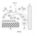
圖6(a)、(b)係對使用SAV方式之蝕刻進行說明之圖。Fig. 6 (a) and (b) are diagrams explaining the etching using the SAV method.
圖7係表示將一實施形態之蝕刻方法應用於通孔步驟之情形時之蝕刻結果之一例的圖。FIG. 7 is a diagram showing an example of an etching result when the etching method of an embodiment is applied to the through hole step.
圖8(a)、(b)係表示將一實施形態之蝕刻方法應用於Si-ARC之蝕刻步驟之情形時之蝕刻結果之一例的圖。8(a) and (b) are diagrams showing an example of etching results when the etching method of one embodiment is applied to the Si-ARC etching step.
圖9(a)、(b)係表示一實施形態之SiF4氣體之流量比及遮罩選擇比之一例之圖。Figures 9(a) and (b) are diagrams showing an example of SiF4 gas flow rate ratio and mask selection ratio in one embodiment.
圖10係用以對一實施形態之SiF4氣體之添加及遮罩選擇比之機制進行說明之圖。Fig. 10 is adiagram for explaining the mechanism of SiF 4 gas addition and mask selection ratio in an embodiment.
圖11係表示一實施形態之SiF4氣體之添加量及遮罩選擇比之一例之圖。Fig. 11 is a diagram showing anexample of the amount of SiF 4 gas added and the mask selection ratio in one embodiment.
以下,參照圖式對用以實施本發明之形態進行說明。再者,於本說明書及圖式中,關於實質上相同之構成,藉由標註相同之符號而省略重複之說明。Hereinafter, a mode for implementing the present invention will be described with reference to the drawings. Furthermore, in this specification and the drawings, for substantially the same configuration, the same symbols are used to omit repeated descriptions.
[蝕刻裝置之整體構成][The overall structure of the etching device]
首先,參照圖1對藉由本發明之一實施形態之蝕刻方法對半導體晶圓(以下簡稱為「晶圓」)執行電漿蝕刻的蝕刻裝置1進行說明。圖1表示本實施形態之蝕刻裝置1之縱截面之一例。本實施形態之蝕刻裝置1係對向配置有亦作為下部電極發揮功能之載置台20、及亦作為上部電極發揮功能之氣體簇射頭25的平行平板型蝕刻裝置(電容耦合型蝕刻裝置)。First, referring to FIG. 1, an etching apparatus 1 that performs plasma etching on a semiconductor wafer (hereinafter referred to as "wafer") by an etching method according to an embodiment of the present invention will be described. Fig. 1 shows an example of a longitudinal section of an etching apparatus 1 of this embodiment. The etching apparatus 1 of this embodiment is a parallel plate type etching apparatus (capacitive coupling type etching apparatus) in which a mounting table 20 that also functions as a lower electrode and a
蝕刻裝置1包含例如表面經氧化鋁膜處理(陽極氧化處理)之包含鋁之圓筒形之處理容器10。處理容器10電性接地。載置台20設置於處理容器10之底部,且載置晶圓W。晶圓W係被處理體之一例。載置台20例如由鋁(Al)或鈦(Ti)、碳化矽(SiC)等形成。於載置台20之上表面,設置有用以靜電吸附晶圓W之靜電吸盤106。靜電吸盤106成為於絕緣體106b之間夾入吸盤電極106a而成之構造。於吸盤電極106a連接有直流電壓源112,藉由自直流電壓源112對吸盤電極106a施加直流電壓HV,而藉由庫侖力將晶圓W吸附於靜電吸盤106。The etching apparatus 1 includes, for example, a
載置台20由支持體104支持。於支持體104之內部形成有冷媒流路104a。於冷媒流路104a連接有冷媒入口配管104b及冷媒出口配管104c。自冷卻器107輸出之例如冷卻水或鹽水等冷卻媒體(以下亦稱為「冷媒」)係於冷媒入口配管104b、冷媒流路104a及冷媒出口配管104c中循環。藉由冷媒,而載置台20及靜電吸盤106被除熱,從而冷卻。The mounting table 20 is supported by the
傳熱氣體供給源85係將氦氣(He)或氬氣(Ar)等傳熱氣體通過氣體供給管線130而供給至靜電吸盤106上之晶圓W之背面。藉由該構成,靜電吸盤106係藉由在冷媒流路104a中循環之冷媒、及供給至晶圓W之背面之傳熱氣體而進行溫度控制,其結果,可將晶圓控制為特定之溫度。The heat transfer
於載置台20,連接有供給雙頻重疊電力之電力供給裝置30。電力供給裝置30包含:第1高頻電源32,其供給第1頻率之第1高頻電力(電漿產生用高頻電力);及第2高頻電源34,其供給低於第1頻率之第2頻率之第2高頻電力(偏壓電壓產生用高頻電力)。第1高頻電源32經由第1匹配器33而電性連接於載置台20。第2高頻電源34經由第2匹配器35而電性連接於載置台20。第1高頻電源32例如將60MHz之第1高頻電力施加至載置台20。第2高頻電源34例如將13.56MHz之第2高頻電力施加至載置台20。再者,於本實施形態中,第1高頻電力施加至載置台20,但亦可施加至氣體簇射頭25。A
第1匹配器33使負載阻抗與第1高頻電源32之內部(或輸出)阻抗匹配。第2匹配器35使負載阻抗與第2高頻電源34之內部(或輸出)阻抗匹配。第1匹配器33係以如下方式發揮功能,即,於在處理容器10內產生電漿時,第1高頻電源32之內部阻抗與負載阻抗表觀上一致。第2匹配器35係以如下方式發揮功能,即,於在處理容器10內產生電漿時,第2高頻電源34之內部阻抗與負載阻抗表觀上一致。The
氣體簇射頭25係以介隔被覆其周緣部之遮蔽環40將處理容器10之頂壁部之開口封閉之方式安裝。於氣體簇射頭25連接有可變直流電源70,且自可變直流電源70被施加特定之直流(DC)電壓。氣體簇射頭25亦可由矽形成。The
於氣體簇射頭25形成有將氣體導入之氣體導入口45。於氣體簇射頭25之內部設置有自氣體導入口45分支之中心側之擴散室50a及邊緣側之擴散室50b。自氣體供給源15輸出之氣體經由氣體導入口45而供給至擴散室50a、50b,並於擴散室50a、50b擴散而自多個氣體供給孔55朝向載置台20導入。A
於處理容器10之底面形成有排氣口60,藉由連接於排氣口60之排氣裝置65而將處理容器10內排氣。藉此,可將處理容器10內維持為特定之真空度。於處理容器10之側壁設置有閘閥G。閘閥G係於進行晶圓W自處理容器10之搬入及搬出時,開閉搬入搬出口。An
於蝕刻裝置1,設置有對裝置整體之動作進行控制之控制部100。控制部100包含CPU(Central Processing Unit,中央處理單元)105、ROM(Read Only Memory,唯讀記憶體)110及RAM(Random Access Memory,隨機存取記憶體)115。CPU105係依據儲存於該等記憶區域之各種製程配方,執行下述之蝕刻等所需之處理。於製程配方中記載有對於蝕刻條件等處理條件之裝置之控制資訊即製程時間、壓力(氣體之排出)、高頻電力或電壓、各種氣體流量、處理容器內溫度(上部電極溫度、處理容器之側壁溫度、晶圓W溫度、靜電吸盤溫度等)、及冷卻器107之冷媒溫度等。再者,該等程式或表示處理條件之製程配方亦可記憶於硬碟或半導體記憶體中。又,製程配方亦可以收容於CD-ROM(Compact Disc Read Only Memory,唯讀光碟)、DVD(Digital Versatile Disc,數位多功能光碟)等可攜性之能夠藉由電腦讀取之記憶媒體之狀態設置於特定位置並讀取。The etching apparatus 1 is provided with a
於進行蝕刻時,控制閘閥G之開閉,而將晶圓W搬入至處理容器10,並載置於載置台20。藉由自直流電壓源112對吸盤電極106a施加直流電壓HV,而藉由庫侖力將晶圓W吸附並保持於靜電吸盤106。When etching is performed, the opening and closing of the gate valve G is controlled, and the wafer W is carried into the
繼而,將處理氣體、高頻電力供給至處理容器10內,而產生電漿。藉由所產生之電漿而對晶圓W進行電漿處理。於電漿處理後,對吸盤電極106a施加正負與晶圓W之吸附時相反之直流電壓HV,將晶圓W之電荷去除,而將晶圓W自靜電吸盤106剝離。控制閘閥G之開閉,而將晶圓W自處理容器10搬出。Then, processing gas and high-frequency power are supplied into the
[蝕刻方法][Etching method]
於本實施形態中,使用上述構成之蝕刻裝置1,將多晶矽(Poly-Si)、氮化矽(SiN)膜、光阻劑(PR)、氮化鈦(TiN)膜等抗蝕劑膜作為遮罩而對氧化矽膜(SiOx)進行蝕刻。但是,遮罩之種類並不限於上述例。又,被蝕刻對象膜並不限於氧化矽膜,可應用於Low-k(低介電常數)膜等絕緣層之蝕刻。In this embodiment, the etching device 1 constructed as described above is used, and a resist film such as polysilicon (Poly-Si), silicon nitride (SiN) film, photoresist (PR), titanium nitride (TiN) film, etc. is used as The silicon oxide film (SiOx ) is etched by masking. However, the type of mask is not limited to the above example. In addition, the film to be etched is not limited to a silicon oxide film, and can be applied to the etching of insulating layers such as Low-k (low dielectric constant) films.
若將晶圓搬入至處理容器10內並保持於載置台20,則控制部100開始圖2所示之本實施形態之蝕刻方法。首先,控制部100將向氟碳氣體(含有碳及氟之氣體)中添加四氟化矽(SiF4)氣體所得之混合氣體自氣體供給源15供給至處理容器10內(步驟S10)。於本實施形態中,作為包含碳(C)氣體及氟(F)氣體之氣體之一例,供給四氟化碳(CF4)氣體。但是,氟碳氣體並不限於CF4氣體,亦可為八氟環丁烷(C4F8)氣體、六氟-1,3-丁二烯(C4F6)氣體等。When the wafer is loaded into the
其次,控制部100將自第1高頻電源32輸出之第1頻率之第1高頻電力HF(電漿產生用高頻電力)施加至作為下部電極發揮功能之載置台20(步驟S12)。又,控制部100將自第2高頻電源34輸出之第2頻率之第2高頻電力LF(偏壓電壓產生用高頻電力)施加至載置台20(步驟S12)。Next, the
其次,控制部100自可變直流電源70將負之直流電壓DC輸出至作為上部電極發揮功能之氣體簇射頭25(步驟S14)。於以上之步驟S10~S14所示之蝕刻條件下,產生電漿,並藉由該電漿之作用,介隔遮罩對例如氧化矽膜(SiOx)等含有矽之氧化膜進行蝕刻(步驟S16),本處理結束。Next, the
再者,於步驟S12中,亦可不施加第2高頻電力LF。又,於步驟S14中,亦可不施加負之直流電壓DC。但是,如下述般,施加負之直流電壓DC時遮罩選擇比提高,故而較佳。Furthermore, in step S12, the second high-frequency power LF may not be applied. In addition, in step S14, the negative direct current voltage DC may not be applied. However, as described below, when a negative DC voltage DC is applied, the mask selection ratio increases, which is preferable.
[蝕刻結果1][Etching result 1]
基於圖3~圖5對以上所說明之本實施形態之蝕刻結果1之一例進行說明。圖3~圖5之各曲線圖表示藉由以下之蝕刻條件利用本實施形態之蝕刻方法對氧化矽膜(SiO2)進行蝕刻所得之結果。An example of the etching result 1 of the present embodiment described above will be described based on FIGS. 3 to 5. The graphs in FIGS. 3 to 5 show the resultsof etching the silicon oxide film (SiO 2 ) by the etching method of this embodiment under the following etching conditions.
(蝕刻條件)(Etching conditions)

圖3之曲線圖之橫軸表示供給之SiF4氣體之流量,縱軸表示遮罩選擇比。實線A、B、C、D表示於蝕刻中施加負之直流電壓DC之情形時之蝕刻結果。具體而言,實線A表示將多晶矽之抗蝕劑膜作為遮罩而對氧化矽膜進行蝕刻時之遮罩選擇比。實線B表示將氮化鈦(TiN)作為遮罩(金屬硬質遮罩)而對氧化矽膜進行蝕刻時之遮罩選擇比。實線C表示將光阻劑膜(PR)作為遮罩而對氧化矽膜進行蝕刻時之遮罩選擇比。實線D表示將氮化矽(SiN)膜作為遮罩而對氧化矽膜進行蝕刻時之遮罩選擇比。The horizontal axis of the graph in FIG. 3 representsthe flow rate of SiF 4 gas supplied, and the vertical axis represents the mask selection ratio. The solid lines A, B, C, and D represent the etching results when a negative DC voltage DC is applied during etching. Specifically, the solid line A represents the mask selection ratio when the silicon oxide film is etched using the polysilicon resist film as a mask. The solid line B represents the mask selection ratio when the silicon oxide film is etched using titanium nitride (TiN) as a mask (metal hard mask). The solid line C represents the mask selection ratio when the silicon oxide film is etched using the photoresist film (PR) as a mask. The solid line D represents the mask selection ratio when the silicon oxide film is etched using a silicon nitride (SiN) film as a mask.
再者,右側之縱軸表示將氮化鈦作為遮罩之情形時之遮罩選擇比,左側之縱軸表示將氮化鈦以外之材質作為遮罩之情形時之遮罩選擇比。Furthermore, the vertical axis on the right represents the mask selection ratio when titanium nitride is used as the mask, and the leftThe vertical axis on the side represents the mask selection ratio when materials other than titanium nitride are used as the mask.
另一方面,虛線E、F、G、H表示於蝕刻中未施加負之直流電壓DC之情形時之蝕刻結果。虛線E係藉由與實線A相同之遮罩對氧化矽膜進行蝕刻時之遮罩選擇比。虛線F、G、H係同樣地藉由與實線B、C、D相同之遮罩對氧化矽膜進行蝕刻時之遮罩選擇比。On the other hand, the dashed lines E, F, G, and H represent the etching results when the negative DC voltage DC is not applied during etching. The dotted line E is the mask selection ratio when the silicon oxide film is etched with the same mask as the solid line A. The broken lines F, G, and H indicate the mask selection ratios when the silicon oxide film is etched with the same masks as the solid lines B, C, and D.
根據圖3之結果可知,根據本實施形態之蝕刻方法,可藉由在CF4氣體中添加SiF4氣體而使遮罩選擇比提高。又,SiF4氣體相對於CF4氣體之添加量越多,則越能夠使遮罩選擇比提高。進而,於氮化鈦(TiN)之情形時,與將其他材質作為遮罩而進行蝕刻相比,遮罩選擇比明顯提高。進而,可知,藉由在蝕刻中施加DC而可使遮罩選擇比進一步提高。但是,若SiF4氣體之流量變得過多,則難以進行氧化矽膜等之蝕刻。According to the result of FIG. 3, it can be seen that according to the etching method of this embodiment, the mask selection ratio can be improved by adding SiF4gas to CF 4 gas. In addition, thegreater the amount of SiF 4 gas added to the CF4 gas, the more the mask selection ratio can be improved. Furthermore, in the case of titanium nitride (TiN), compared to etching with other materials as a mask, the mask selection ratio is significantly improved. Furthermore, it can be seen that the mask selection ratio can be further improved by applying DC during etching. However, ifthe flow rate of the SiF 4 gas becomes excessive, it becomes difficult to perform etching of the silicon oxide film or the like.
圖4之橫軸表示於蝕刻中施加負之直流電壓DC且SiF4氣體相對於所有處理氣體(CF4+SiF4)之流量比。圖4之縱軸(左側)表示SiO2之蝕刻速率(Etching rate)(以下亦稱為「ER」)。圖4之縱軸(右側)表示遮罩選擇比。The horizontal axis of FIG. 4 represents the flow rate ratio ofSiF 4 gas to all processing gases (CF4 +SiF4) when a negative DC voltage DC is applied during etching. The vertical axis (left side) of FIG. 4 representsthe etching rate of SiO 2 (hereinafter also referred to as "ER"). The vertical axis (right side) of Fig. 4 represents the mask selection ratio.
圖4之曲線圖中之實線I、J、K、L、M表示ER,虛線N、O、P、R表示遮罩選擇比。實線I表示將氧化膜(Ox)作為遮罩而對氧化矽膜進行蝕刻時之ER。實線J表示將氮化矽(SiN)膜作為遮罩而對氧化矽膜進行蝕刻時之ER。實線K表示將氮化鈦(TiN)膜作為遮罩而對氧化矽膜進行蝕刻時之ER。實線L表示將多晶矽膜(Poly)作為遮罩而對氧化矽膜進行蝕刻時之ER。實線M表示將光阻劑(PR)作為遮罩而對氧化矽膜進行蝕刻時之ER。The solid lines I, J, K, L, and M in the graph of Fig. 4 represent ER, and the dashed lines N, O, P, and R represent the mask selection ratio. The solid line I represents the ER when the silicon oxide film is etched using theoxide film (O x) as a mask. The solid line J represents the ER when the silicon oxide film is etched using the silicon nitride (SiN) film as a mask. The solid line K represents the ER when the silicon oxide film is etched using the titanium nitride (TiN) film as a mask. The solid line L represents the ER when the silicon oxide film is etched using the polysilicon film (Poly) as a mask. The solid line M represents the ER when the silicon oxide film is etched using the photoresist (PR) as a mask.
又,圖4之虛線N表示將多晶矽膜(Poly)作為遮罩而對氧化矽膜進行蝕刻時之遮罩選擇比。線O表示將光阻劑(PR)作為遮罩而對氧化矽膜進行蝕刻時之遮罩選擇比。線P表示將氮化矽(SiN)膜作為遮罩而對氧化矽膜進行蝕刻時之遮罩選擇比。線R表示將氮化鈦(TiN)膜作為遮罩而對氧化矽膜進行蝕刻時之遮罩選擇比。In addition, the dotted line N in FIG. 4 represents the mask selection ratio when the silicon oxide film is etched using the polysilicon film (Poly) as a mask. Line O represents the mask selection ratio when the silicon oxide film is etched using the photoresist (PR) as a mask. Line P indicates that the silicon nitride (SiN) film is used as a mask and the silicon oxide film isMask selection ratio during etching. The line R represents the mask selection ratio when the silicon oxide film is etched using a titanium nitride (TiN) film as a mask.
根據以上之結果可知,即便選擇虛線N、O、P、R所示之任一素材作為遮罩,若添加SiF4氣體則遮罩選擇比均提高。尤其是,較佳為於蝕刻中施加DC且以SiF4氣體相對於所有處理氣體(CF4+SiF4)之流量比成為10%至75%之範圍之方式控制SiF4氣體之添加量。藉此,可提高遮罩選擇比。From the above results, it can be seen that even if any of the materials shown by the broken lines N, O, P, and R are selected as the mask, the mask selection ratio increases whenSiF 4 gas is added. In particular, it is preferable to apply DC during etching andcontrol the amount of SiF 4 gas added so thatthe flow ratio of SiF 4 gas to all processing gases (CF4 +SiF4 ) is in the range of 10% to 75%. In this way, the mask selection ratio can be improved.
進而,根據圖4之結果,若於蝕刻中施加DC且以SiF4氣體相對於所有處理氣體(CF4+SiF4)之流量比成為50%至75%之範圍之方式控制SiF4氣體之添加量,則可進一步提高遮罩選擇比,故而更佳。Furthermore, according to the result of FIG. 4, if DC is applied during etching andthe flow rate ratio of SiF 4 gas to all processing gases (CF4 + SiF4 ) is controlled to be in the range of 50% to 75%, the addition ofSiF 4 gas is controlled It can further increase the mask selection ratio, so it is better.
又,可知,即便選擇實線I、J、K、L、M所示之任一素材作為遮罩,若添加SiF4氣體則ER均稍微降低,但如圖5所示,於晶圓W之徑向上可保持ER之面內均一性(Uniformity)。亦即,可知,即便於添加SiF4氣體之情形時,晶圓之徑向之ER之面內均一性(Uniformity)亦為「2.7」,與未添加SiF4氣體之情形時之晶圓之徑向之ER之面內均一性「3.2」同樣地,可保持ER之面內均一性。In addition, it can be seen that even if any of the materials shown by the solid lines I, J, K, L, and M is selected as a mask, if SiF4 gas is added, the ER is slightly lowered, but as shown in FIG. The in-plane uniformity of the ER can be maintained in the radial direction. That is, it can be seen that even when SiF4 gas is added, the uniformity of the ER in the radial direction of the wafer is "2.7", which is the same as the diameter of the wafer whenSiF 4 gas is not added. In-plane uniformity of ER to "3.2" Similarly, the in-plane uniformity of ER can be maintained.
[蝕刻結果2][Etching result 2]
其次,對應用本實施形態之蝕刻方法之情形時之蝕刻結果2進行說明。關於以上所說明之本實施形態之蝕刻方法,例如可於使用自對準通孔(SAV:Self-Aligned Via)方式之蝕刻時使用本實施形態之蝕刻方法。於使用SAV方式之方法中,將抗蝕劑等有機膜、及由氮化鈦等含有金屬之膜形成之硬質遮罩作為遮罩,藉由本實施形態之蝕刻方法進行蝕刻。藉此,例如可於用作配線層間膜之低介電常數膜(Low-k膜)形成孔。參照圖6,對使用SAV方式之本實施形態之蝕刻方法進行說明。Next, the
於使用SAV方式之蝕刻方法中,於藉由包含氟碳氣體之處理氣體之電漿對低介電常數膜(Low-k膜)進行蝕刻時,將有機膜及含有金屬之膜作為遮罩而進行蝕刻,藉此,於Low-k膜形成孔等。再者,所謂Low-k膜係相對介電常數低於SiO2之膜之總稱。In the etching method using the SAV method, when the low dielectric constant film (Low-k film) is etched by the plasma of the process gas containing fluorocarbon gas, the organic film and the metal-containing film are used as masks. Etching is performed, thereby forming holes and the like in the Low-k film. Furthermore, the so-called Low-k film is a general term forfilms with a relative dielectric constant lower than that of SiO 2.
如圖6(a)所示,於晶圓W上,於作為被蝕刻對象膜之Low-k膜201上依序積層有四乙氧基矽烷202(TEOS)、TiN膜203。TiN膜203係含有金屬之膜之一例。Low-k膜201例如為SiOCH膜。再者,亦可於晶圓W與Low-k膜201之間形成基底膜。As shown in FIG. 6(a), on the wafer W, a tetraethoxysilane 202 (TEOS) and a
於使用SAV方式對晶圓W進行蝕刻之情形時,首先,如圖6(a)所示,將TiN膜203作為遮罩而對Low-k膜201進行蝕刻。藉此,如圖6(b)所示,於Low-k膜201形成通孔V(通孔步驟)。此時,若TiN膜203相對於Low-k膜201之選擇比不充分,則有於將TiN膜203作為遮罩而進行電漿蝕刻時TiN膜203之一部分被侵蝕而發生所謂入侵(encroachment)之虞。When the wafer W is etched using the SAV method, first, as shown in FIG. 6(a), the Low-
圖7係對在通孔(Via)步驟中應用本實施形態之蝕刻方法之情形時之入侵之效果進行說明的圖。且係包含隔開特定之間隙S而排列之線L之線與間隙(L/S)圖案之概略俯視圖及剖視圖。如圖7所示,入侵係包含隔開特定之間隙S而排列之線L之圖案中形成孔VH之前之線L之寬度L1與形成孔VH之後之線L之寬度L2之差,且由(L1-L2)規定。FIG. 7 is a diagram for explaining the effect of invasion when the etching method of this embodiment is applied in the via step. And it is a schematic plan view and a cross-sectional view of the line and gap (L/S) pattern of the line L arranged to separate the specific gap S. As shown in FIG. 7, the invasion includes the difference between the width L1 of the line L before the hole VH is formed and the width L2 of the line L after the hole VH is formed in the pattern of the lines L arranged with a specified gap S, and is determined by ( L1-L2) regulations.
圖7之左側之通孔步驟表示比較例且於將TiN膜203作為遮罩之Low-k膜201之蝕刻時未向包含氟碳之處理氣體中添加SiF4氣體之情形時之蝕刻結果之一例。圖7之中央表示本實施形態之一例且於將TiN膜203作為遮罩之Low-k膜201之蝕刻時向包含氟碳之處理氣體中添加SiF4氣體之情形時之蝕刻結果之一例。圖7之右側表示本實施形態之一例且於溝槽步驟中向包含氟碳之處理氣體中添加SiF4氣體之情形時之蝕刻結果之一例。The through hole step on the left side of FIG. 7 shows a comparative example and an example of the etching result whenSiF 4 gas is not added to the processing gas containing fluorocarbon during the etching of the Low-
根據該結果,於通孔步驟中,本實施形態之向包含氟碳之處理氣體中添加SiF4氣體之情形時之入侵為「8.2」,比較例之未添加SiF4氣體之情形時之入侵為「18.4」。由此,可知,藉由將本實施形態之蝕刻方法應用於通孔步驟,而TiN之遮罩之一部分幾乎未被侵蝕,而入侵得以抑制。又,如圖7之由粗線包圍之部分所示,於在通孔步驟及溝槽步驟中如本實施形態般向處理氣體中添加SiF4氣體之情形時,與比較例之未添加SiF4氣體之情形相比,遮罩之殘膜增加。亦即,可知遮罩選擇比提高。According to this result, in the through hole step, the invasion when SiF 4 gas is added to the processing gas containing fluorocarbon in this embodiment is "8.2", and the invasion whenSiF 4 gas is not added in the comparative example is "18.4". From this, it can be seen that by applying the etching method of this embodiment to the through hole step, a part of the TiN mask is hardly corroded, and the invasion is suppressed.Moreover, as shown in the part surrounded by the thick line in FIG. 7, when SiF 4 gas is added to the processing gas in the through hole step and the trench step as in this embodiment, it is the same asthe case where SiF 4 is not added in the comparative example. Compared with the case of gas, the residual film of the mask increases. That is, it can be seen that the mask selection ratio is improved.
[蝕刻結果3][Etching result 3]
圖8表示於矽抗反射膜(Si-ARC)之蝕刻中應用本實施形態之蝕刻方法之情形時之蝕刻結果之一例。圖8(a)之左側表示於利用有機膜之遮罩對基底膜301上之含有矽之抗反射膜(Si-ARC)302進行蝕刻時未向包含氟碳之處理氣體中添加SiF4氣體之情形時之蝕刻結果之一例。圖8(a)之右側表示於利用有機膜之遮罩對Si-ARC302進行蝕刻時向包含氟碳之處理氣體中添加SiF4氣體之情形時之蝕刻結果之一例。FIG. 8 shows an example of an etching result when the etching method of this embodiment is applied to the etching of a silicon anti-reflective film (Si-ARC). The left side of FIG. 8(a) shows that the silicon-containing anti-reflective film (Si-ARC) 302 on the
圖8表示藉由以下之蝕刻條件利用本實施形態之蝕刻方法對Si-ARC302進行蝕刻所得之結果。FIG. 8 shows the result of etching Si-ARC302 using the etching method of this embodiment under the following etching conditions.
(蝕刻條件)(Etching conditions)

於圖8(a)及圖8(b)中,比較例(未添加SiF4氣體)之Si-ARC302與本實施形態(添加有SiF4氣體)之Si-ARC302相比前端變細,而產生Si-ARC302之頂部CD(Critical Dimension,臨界尺寸)(TCD:孔上部之CD)與底部CD(BCD:孔底部之CD)之差變大之CD收縮。相對於此,於本實施形態中,CD收縮變小,而蝕刻形狀變得良好。In Fig. 8(a) and Fig. 8(b),the Si-ARC302 of the comparative example (without SiF 4 gas) is thinner than the Si-ARC302 of the present embodiment (with SiF4 gas), resulting in The difference between the top CD (Critical Dimension) (TCD: CD at the top of the hole) and the bottom CD (BCD: CD at the bottom of the hole) of Si-ARC302 becomes larger, and the CD shrinks. On the contrary, in this embodiment, the CD shrinkage becomes smaller, and the etching shape becomes better.
又,如圖8(b)所示,可知,於本實施形態(添加有SiF4氣體)之Si-ARC302,與比較例(未添加SiF4氣體)之Si-ARC302相比殘膜變多,而遮罩選擇比提高。Moreover, as shown in FIG. 8(b), it can be seen thatthe Si-ARC302 of this embodiment (with SiF 4 gas added) has more residual film than the Si-ARC302 of the comparative example (with no SiF4 gas added). The mask selection ratio is improved.
[蝕刻結果4][Etching result 4]
圖9(a)之橫軸表示SiF4氣體相對於所有處理氣體(CF4+SiF4)之流量比。圖9(a)之縱軸表示電漿中之SiF、CF2、CF、F之強度之比率。再者,於強度之測定時,CF2之強度可藉由檢測252nm之波長之光而獲得。CF之強度可藉由檢測256nm之波長之光而獲得。F之強度可藉由檢測704nm之波長之光而獲得。The horizontal axis of Fig. 9(a) represents the flow rate ratio ofSiF 4 gas to all processing gases (CF4 + SiF4 ). The vertical axis of Fig. 9(a) representsthe ratio of the intensities of SiF, CF 2 , CF, and F in the plasma. Furthermore, when measuring the intensity, the intensity of CF2 can be obtained by detecting light with a wavelength of 252 nm. The intensity of CF can be obtained by detecting light with a wavelength of 256nm. The intensity of F can be obtained by detecting light with a wavelength of 704 nm.
根據該結果可知,可藉由改變SiF4氣體相對於所有處理氣體(CF4+SiF4)之流量比而改變電漿之組成。具體而言,可知,SiF4氣體相對於所有處理氣體(CF4+SiF4)之流量比越高,則高價之CF成分(CF2)與低價之CF成分或F成分相比越是相對性地增加。From this result, it can be seen that the composition of the plasmacan be changed by changing the flow ratio of SiF 4 gas to all processing gases (CF4 +SiF4 ). Specifically, it can be seen that thehigher the flow rate ratio of SiF 4 gas to all processing gases (CF4 + SiF4 ), the more expensive the CF component (CF2 ) is compared to the low-priced CF component or F component. Sexually increase.
圖9(b)之橫軸表示SiF4氣體相對於所有處理氣體(CF4+SiF4)之流量比。圖9(b)之縱軸(左側)表示遮罩選擇比,圖9(b)之縱軸(右側)表示CF2之強度相對於電漿中之F之比率。The horizontal axis of Fig. 9(b) represents the flow rate ratio ofSiF 4 gas to all processing gases (CF4 + SiF4 ). The vertical axis (left side) of Fig. 9(b) represents the mask selection ratio, and the vertical axis (right side) of Fig. 9(b) representsthe ratio of the intensity of CF 2 to the F in the plasma.
圖9(b)之實線S表示將多晶矽之抗蝕劑膜作為遮罩而對氧化矽膜進行蝕刻時之遮罩選擇比。實線T表示將氮化矽(SiN)膜作為遮罩而對氧化矽膜進行蝕刻時之遮罩選擇比。實線U表示將光阻劑膜(PR)作為遮罩而對氧化矽膜進行蝕刻時之遮罩選擇比。實線V表示藉由OES(Optical Emission Spectroscopy,光發射光譜學)而獲得之電漿中之CF2/F之發光強度比。所謂OES係指對自放電電漿中獲得之元素固有之明線光譜(原子光譜)之波長進行定性並根據發光強度進行定量的方法。The solid line S in FIG. 9(b) represents the mask selection ratio when the silicon oxide film is etched using the polysilicon resist film as a mask. The solid line T represents the mask selection ratio when the silicon oxide film is etched using a silicon nitride (SiN) film as a mask. The solid line U represents the mask selection ratio when the silicon oxide film is etched using the photoresist film (PR) as a mask. The solid line V represents the luminous intensity ratioof CF 2 /F in the plasma obtained by OES (Optical Emission Spectroscopy). The so-called OES refers to the method of qualitatively determining the wavelength of the bright line spectrum (atomic spectrum) of the element obtained in the self-discharge plasma and quantifying it based on the luminous intensity.
據此可知,SiF4氣體相對於所有處理氣體(CF4+SiF4)之流量比越高,則遮罩選擇比越是提高。根據以上情況可知,藉由提高處理氣體中之SiF4氣體之流量比,而遮罩選擇比提高。而且,可知,SiF4氣體相對於所有處理氣體(CF4+SiF4)之流量比越高,則電漿中之高價之CF成分(CF2)與低價之CF成分或F成分相比越是相對性地增加。From this, it can be seen that thehigher the flow rate ratio of SiF 4 gas to all processing gases (CF4 +SiF4 ), the higher the mask selection ratio. Based on the above, it can be seen that by increasingthe flow ratio of SiF 4 gas in the processing gas, the mask selection ratio is increased. Moreover, it can be seen that thehigher the flow rate ratio of SiF 4 gas to all processing gases (CF4 + SiF4 ), the more expensive the CF component (CF2 ) in the plasma is compared to the low-priced CF component or F component. It is a relative increase.
[SiF4氣體之添加及遮罩選擇比][SiF4 gas addition and mask selection ratio]
其次,對SiF4氣體之添加及遮罩選擇比進行說明。根據上述蝕刻結果,設想如下關係,即,若電漿中之高價之CF成分(CF2)與低價之CF成分或F成分相比相對性地增加,則遮罩選擇比提高。Next, the addition of SiF4 gas and the mask selection ratio will be described. Based on the above-mentioned etching results, it is assumed that if the high-priced CF component (CF2 ) in the plasma increases relative to the low-priced CF component or F component, the mask selection ratio will increase.
作為前提,已知,電漿中之滯留時間(自由基於電漿空間滯留之時間)越長,則越會自CF自由基解離成F自由基,而成為與CF自由基相比F自由基之比率相對較高之電漿。As a prerequisite, it is known that the longer the residence time in the plasma (the time that the free stays in the plasma space), the more dissociated from the CF radicals into F radicals, which are compared with CF radicals. Plasma with relatively high ratio.
此處,列舉將氮化鈦(TiN)作為遮罩而對氧化矽膜(SiO2)進行蝕刻之情形為例,表示自SiF4氣體產生富含F之電漿(與CF自由基相比F自由基之比率相對較高之電漿)時之化學反應式。Here, a case where a silicon oxide film (SiO2 ) is etched using titanium nitride (TiN) as a mask is taken as an example, which means thatF-rich plasma is generated from SiF 4 gas (compared with CF radicals, F The chemical reaction formula when the ratio of free radicals is relatively high in plasma).
.自SiF4氣體至富含F之電漿. From SiF4 gas to F-rich plasma
TiN#+2F2 → TiF4+N2…(1-1)TiN#+2F2 → TiF4 +N2 …(1-1)
SiO2+2F2 → SiF4+O2…(1-2)SiO2 +2F2 → SiF4 +O2 …(1-2)
同樣地,表示自SiF4氣體產生富含CF之電漿(與F自由基相比CF自由基之比率相對較高之電漿)時之化學反應式。Similarly, it represents the chemical reaction formula when CF-rich plasma (a plasma with a relatively high ratio of CF radicals compared to F radicals) is generatedfrom SiF 4 gas.
.自SiF4氣體至富含CF之電漿. From SiF4 gas to CF-rich plasma
TiN#+2CF2 → TiF4+N2+C#N#+C…(2-1)TiN#+2CF2 → TiF4 +N2 +C#N#+C…(2-1)
SiO2+2CF2 → SiF4+2CO…(2-2)SiO2 +2CF2 → SiF4 +2CO…(2-2)
若對以上兩組化學式進行比較,則可知,於富含CF之電漿中,如式(2-1)所示,碳C堆積於氮化鈦之遮罩之表面。參照模式性地表示蝕刻裝置1內之晶圓W上之電漿空間之圖10,對因富含CF之電漿之作用而碳C堆積於氮化鈦之遮罩之表面之機制進行說明。If the above two chemical formulas are compared, it can be seen that in the CF-rich plasma, as shown in formula (2-1), carbon C is deposited on the surface of the titanium nitride mask. Referring to FIG. 10 schematically showing the plasma space on the wafer W in the etching apparatus 1, the mechanism of carbon C being deposited on the surface of the titanium nitride mask due to the action of the CF-rich plasma will be described.
若向供給至處理容器10內之包含氟碳氣體之處理氣體中添加SiF4氣體,則產生包含電子、離子、CF自由基(CF*)、F自由基(F*)、及SiF自由基(SiF*)之電漿。電漿中之SiF自由基與F自由基進行化學反應而變成SiF4。SiF4係蒸汽壓較高,而立即揮發。因此,SiF4變成氣體而排出至處理容器10外。If SiF 4 gas is added to the processing gas containing fluorocarbon gas supplied to the
另一方面,SiF自由基不與CF自由基反應。其結果,電漿中之F自由基之濃度未上升,且CF自由基之濃度未降低。因此,即便電漿中之滯留時間變長,亦可維持與F自由基相比CF自由基之比率相對較高之富含CF之電漿之狀態。藉此,電漿中之碳C堆積於氮化鈦之遮罩之表面,而碳層塗覆遮罩。認為於本實施形態之蝕刻方法中,於蝕刻中,遮罩表面之碳層作為保護膜發揮功能,因此遮罩選擇比提高。On the other hand, SiF radicals do not react with CF radicals. As a result, the concentration of F radicals in the plasma did not increase, and the concentration of CF radicals did not decrease. Therefore, even if the residence time in the plasma becomes longer, the CF-rich plasma state can be maintained in which the ratio of CF radicals is relatively higher than that of F radicals. Thereby, the carbon C in the plasma is deposited on the surface of the mask of titanium nitride, and the carbon layer coats the mask. It is considered that in the etching method of the present embodiment, the carbon layer on the mask surface functions as a protective film during etching, and therefore the mask selection ratio is improved.
[蝕刻結果5][Etching result 5]
最後,參照圖11,對應用本實施形態之蝕刻方法之情形時之蝕刻結果5進行說明。圖11之左側表示於通孔步驟及溝槽步驟中向CF4氣體及Ar氣體中以添加量A添加SiF4氣體之情形時之蝕刻結果之一例,圖11之右側表示向包含CF4氣體及Ar氣體之處理氣體中以多於添加量A之添加量B添加SiF4氣體之情形時之蝕刻結果之一例。Finally, referring to FIG. 11, the
於任一情形時,均表示距直徑為300mm之晶圓W之邊緣之距離為30mm之晶圓位置及距邊緣之距離為5mm之晶圓位置上之蝕刻結果。據此,於晶圓W之外周30mm及最外周5mm處,遮罩(例如,TiN膜203)之遮罩選擇比提高,而被蝕刻對象膜(例如,Low-k膜201)未前端變細而成為良好之蝕刻形狀。In either case, it means the result of etching on a wafer position with a distance of 30 mm from the edge of a wafer W with a diameter of 300 mm and a wafer position with a distance of 5 mm from the edge. According to this, the mask selection ratio of the mask (for example, TiN film 203) is improved at the 30 mm outer circumference and 5 mm of the outermost circumference of the wafer W, but the target film to be etched (for example, Low-k film 201) does not become thinner. It becomes a good etching shape.
又,如圖11之右側般可知,藉由增加SiF4氣體之添加量,而於晶圓W之外周30mm及最外周5mm之任一處,頂部CD(TCD:孔上部之CD)、中部CD(MCD:孔中央部之CD)、底部CD(BCD:孔底部之CD)之差變得更小。如此,根據本實施形態之蝕刻方法,即便於難以獲得均一之蝕刻之晶圓W之外周側亦確保蝕刻之垂直性。藉此,根據本實施形態之蝕刻方法,即便於晶圓之外周側亦可與內周側同樣地均一地使遮罩選擇比提高。Also, as shown on the right side of Figure 11, by increasing the amount of SiF4 gas added, the top CD (TCD: CD at the top of the hole) and the CD at the top 30 mm and 5 mm from the outermost periphery of the wafer W The difference between (MCD: CD at the center of the hole) and bottom CD (BCD: CD at the bottom of the hole) becomes smaller. In this way, according to the etching method of this embodiment, the verticality of etching is ensured even on the outer peripheral side of the wafer W where it is difficult to obtain uniform etching. Thus, according to the etching method of the present embodiment, the mask selection ratio can be uniformly improved even on the outer peripheral side of the wafer as in the inner peripheral side.
根據以上情況,可藉由向包含氟碳之處理氣體中添加SiF4氣體,而亦包括外周側在內地使晶圓W之遮罩選擇比整體提高。According to the above situation, by adding SiF4 gas to the processing gas containing fluorocarbon, the mask selection ratio of the wafer W can be increased as a whole including the outer peripheral side.
但是,若於處理氣體中包含二氧化碳(CO2)氣體、一氧化碳(CO)氣體、及氧氣(O2),則會產生稱為SiO之氧化膜,且於蝕刻中堆積,因此蝕刻變得困難。因此,本實施形態之蝕刻方法中使用之處理氣體不包含含有碳C及氧O之兩者之氣體。又,本實施形態之蝕刻方法中使用之處理氣體不包含氧氣O2。However, if carbon dioxide (CO 2 ) gas, carbon monoxide (CO) gas, and oxygen (O2 ) are contained in the processing gas, an oxide film called SiO is generated and deposited during etching, so etching becomes difficult. Therefore, the processing gas used in the etching method of this embodiment does not include a gas containing both carbon C and oxygen O. In addition, the processing gas used in the etching method of this embodiment does not contain oxygen O2 .
以上,藉由上述實施形態對蝕刻方法進行了說明,但本發明之蝕刻方法並不限定於上述實施形態,可於本發明之範圍內進行各種變化及改良。上述複數個實施形態中記載之事項可於不矛盾之範圍內組合。Above, the etching method has been explained based on the above embodiment, but the etching method of the present inventionThe method is not limited to the above-mentioned embodiment, and various changes and improvements can be made within the scope of the present invention. The matters described in the above plural embodiments can be combined within the scope of non-contradictory.
例如,本發明之蝕刻方法可應用於電容耦合型電漿(CCP:Capacitively Coupled Plasma)裝置。本發明之蝕刻方法難以應用於作為其他電漿裝置之電感耦合型電漿(ICP:Inductively Coupled Plasma)裝置。For example, the etching method of the present invention can be applied to a capacitively coupled plasma (CCP: Capacitively Coupled Plasma) device. The etching method of the present invention is difficult to be applied to inductively coupled plasma (ICP: Inductively Coupled Plasma) devices as other plasma devices.
ICP裝置成為如下構造,即,於處理容器之上部產生電漿,且將電漿於處理容器內不擴散地吸引至載置於處理容器之下方之載置台側。另一方面,於圖1之蝕刻裝置1中表示一例之CCP裝置係使所產生之電漿擴散至處理容器10內之上部、下部、側壁等。如此,於CCP裝置中,電漿擴散至電漿空間,因此,電漿對晶圓W之邊緣側之貢獻率高於ICP裝置。因此,本發明之蝕刻方法係藉由在CCP裝置中使用,而與於ICP裝置中使用之情形相比,藉由向處理氣體中添加SiF4氣體所產生的對晶圓W之外周側之遮罩選擇比之提高等影響大於ICP裝置之情形。The ICP device has a structure in which plasma is generated on the upper part of the processing container, and the plasma is sucked in the processing container to the side of the mounting table placed below the processing container without diffusion. On the other hand, the etching apparatus 1 in FIG. 1 shows an example of a CCP apparatus that diffuses the generated plasma to the upper part, lower part, side wall, etc. of the
於本說明書中,作為蝕刻對象,對半導體晶圓W進行了說明,但亦可為用於LCD(Liquid Crystal Display,液晶顯示器)、FPD(Flat Panel Display,平板顯示器)等之各種基板或光罩、CD基板、印刷基板等。In this specification, the semiconductor wafer W is described as the etching target, but it can also be various substrates or masks used for LCD (Liquid Crystal Display), FPD (Flat Panel Display, Flat Panel Display), etc. , CD substrates, printed circuit boards, etc.
A‧‧‧實線A‧‧‧Solid line
B‧‧‧實線B‧‧‧Solid line
C‧‧‧實線C‧‧‧Solid line
D‧‧‧實線D‧‧‧Solid line
E‧‧‧虛線E‧‧‧dotted line
F‧‧‧虛線F‧‧‧dotted line
G‧‧‧虛線G‧‧‧dotted line
H‧‧‧虛線H‧‧‧dotted line
Claims (4)
Translated fromChineseApplications Claiming Priority (2)
| Application Number | Priority Date | Filing Date | Title |
|---|---|---|---|
| JP2015-231532 | 2015-11-27 | ||
| JP2015231532AJP2017098478A (en) | 2015-11-27 | 2015-11-27 | Etching method |
Publications (2)
| Publication Number | Publication Date |
|---|---|
| TW201729284A TW201729284A (en) | 2017-08-16 |
| TWI725072Btrue TWI725072B (en) | 2021-04-21 |
Family
ID=58777724
Family Applications (1)
| Application Number | Title | Priority Date | Filing Date |
|---|---|---|---|
| TW105137210ATWI725072B (en) | 2015-11-27 | 2016-11-15 | Etching method |
Country Status (4)
| Country | Link |
|---|---|
| US (1) | US9847231B2 (en) |
| JP (1) | JP2017098478A (en) |
| KR (1) | KR102662506B1 (en) |
| TW (1) | TWI725072B (en) |
Families Citing this family (30)
| Publication number | Priority date | Publication date | Assignee | Title |
|---|---|---|---|---|
| US9132436B2 (en) | 2012-09-21 | 2015-09-15 | Applied Materials, Inc. | Chemical control features in wafer process equipment |
| US10256079B2 (en) | 2013-02-08 | 2019-04-09 | Applied Materials, Inc. | Semiconductor processing systems having multiple plasma configurations |
| US11637002B2 (en) | 2014-11-26 | 2023-04-25 | Applied Materials, Inc. | Methods and systems to enhance process uniformity |
| US20160225652A1 (en) | 2015-02-03 | 2016-08-04 | Applied Materials, Inc. | Low temperature chuck for plasma processing systems |
| US9741593B2 (en) | 2015-08-06 | 2017-08-22 | Applied Materials, Inc. | Thermal management systems and methods for wafer processing systems |
| US10504700B2 (en) | 2015-08-27 | 2019-12-10 | Applied Materials, Inc. | Plasma etching systems and methods with secondary plasma injection |
| US10504754B2 (en) | 2016-05-19 | 2019-12-10 | Applied Materials, Inc. | Systems and methods for improved semiconductor etching and component protection |
| US9865484B1 (en) | 2016-06-29 | 2018-01-09 | Applied Materials, Inc. | Selective etch using material modification and RF pulsing |
| US10546729B2 (en) | 2016-10-04 | 2020-01-28 | Applied Materials, Inc. | Dual-channel showerhead with improved profile |
| US10431429B2 (en) | 2017-02-03 | 2019-10-01 | Applied Materials, Inc. | Systems and methods for radial and azimuthal control of plasma uniformity |
| US10943834B2 (en) | 2017-03-13 | 2021-03-09 | Applied Materials, Inc. | Replacement contact process |
| US11276590B2 (en) | 2017-05-17 | 2022-03-15 | Applied Materials, Inc. | Multi-zone semiconductor substrate supports |
| US11276559B2 (en) | 2017-05-17 | 2022-03-15 | Applied Materials, Inc. | Semiconductor processing chamber for multiple precursor flow |
| JP7176860B6 (en) | 2017-05-17 | 2022-12-16 | アプライド マテリアルズ インコーポレイテッド | Semiconductor processing chamber to improve precursor flow |
| US10297458B2 (en) | 2017-08-07 | 2019-05-21 | Applied Materials, Inc. | Process window widening using coated parts in plasma etch processes |
| US10903054B2 (en) | 2017-12-19 | 2021-01-26 | Applied Materials, Inc. | Multi-zone gas distribution systems and methods |
| US11328909B2 (en) | 2017-12-22 | 2022-05-10 | Applied Materials, Inc. | Chamber conditioning and removal processes |
| US10854426B2 (en) | 2018-01-08 | 2020-12-01 | Applied Materials, Inc. | Metal recess for semiconductor structures |
| US10964512B2 (en) | 2018-02-15 | 2021-03-30 | Applied Materials, Inc. | Semiconductor processing chamber multistage mixing apparatus and methods |
| US10886137B2 (en)* | 2018-04-30 | 2021-01-05 | Applied Materials, Inc. | Selective nitride removal |
| US10892198B2 (en) | 2018-09-14 | 2021-01-12 | Applied Materials, Inc. | Systems and methods for improved performance in semiconductor processing |
| US11049755B2 (en) | 2018-09-14 | 2021-06-29 | Applied Materials, Inc. | Semiconductor substrate supports with embedded RF shield |
| US11062887B2 (en) | 2018-09-17 | 2021-07-13 | Applied Materials, Inc. | High temperature RF heater pedestals |
| US11417534B2 (en) | 2018-09-21 | 2022-08-16 | Applied Materials, Inc. | Selective material removal |
| US11682560B2 (en) | 2018-10-11 | 2023-06-20 | Applied Materials, Inc. | Systems and methods for hafnium-containing film removal |
| US11121002B2 (en) | 2018-10-24 | 2021-09-14 | Applied Materials, Inc. | Systems and methods for etching metals and metal derivatives |
| US11437242B2 (en) | 2018-11-27 | 2022-09-06 | Applied Materials, Inc. | Selective removal of silicon-containing materials |
| US10920319B2 (en) | 2019-01-11 | 2021-02-16 | Applied Materials, Inc. | Ceramic showerheads with conductive electrodes |
| US10886136B2 (en)* | 2019-01-31 | 2021-01-05 | Tokyo Electron Limited | Method for processing substrates |
| JP7390134B2 (en)* | 2019-08-28 | 2023-12-01 | 東京エレクトロン株式会社 | Etching processing method and etching processing equipment |
Citations (2)
| Publication number | Priority date | Publication date | Assignee | Title |
|---|---|---|---|---|
| US6171974B1 (en)* | 1991-06-27 | 2001-01-09 | Applied Materials, Inc. | High selectivity oxide etch process for integrated circuit structures |
| US20140256147A1 (en)* | 2011-09-26 | 2014-09-11 | Tokyo Electron Limited | Plasma processing apparatus and plasma processing method |
Family Cites Families (3)
| Publication number | Priority date | Publication date | Assignee | Title |
|---|---|---|---|---|
| SG140538A1 (en) | 2006-08-22 | 2008-03-28 | Lam Res Corp | Method for plasma etching performance enhancement |
| JP2014007270A (en)* | 2012-06-25 | 2014-01-16 | Tokyo Electron Ltd | Etching method and etching apparatus |
| JP5878091B2 (en)* | 2012-07-20 | 2016-03-08 | 東京エレクトロン株式会社 | Etching method |
- 2015
- 2015-11-27JPJP2015231532Apatent/JP2017098478A/enactivePending
- 2016
- 2016-11-14KRKR1020160151005Apatent/KR102662506B1/enactiveActive
- 2016-11-15USUS15/351,828patent/US9847231B2/enactiveActive
- 2016-11-15TWTW105137210Apatent/TWI725072B/enactive
Patent Citations (2)
| Publication number | Priority date | Publication date | Assignee | Title |
|---|---|---|---|---|
| US6171974B1 (en)* | 1991-06-27 | 2001-01-09 | Applied Materials, Inc. | High selectivity oxide etch process for integrated circuit structures |
| US20140256147A1 (en)* | 2011-09-26 | 2014-09-11 | Tokyo Electron Limited | Plasma processing apparatus and plasma processing method |
Also Published As
| Publication number | Publication date |
|---|---|
| JP2017098478A (en) | 2017-06-01 |
| US9847231B2 (en) | 2017-12-19 |
| KR20170062381A (en) | 2017-06-07 |
| KR102662506B1 (en) | 2024-04-30 |
| US20170154784A1 (en) | 2017-06-01 |
| TW201729284A (en) | 2017-08-16 |
Similar Documents
| Publication | Publication Date | Title |
|---|---|---|
| TWI725072B (en) | Etching method | |
| US9324569B2 (en) | Plasma etching method and plasma etching apparatus | |
| TWI401741B (en) | Plasma etching method | |
| US20210134604A1 (en) | Etching method | |
| TWI692029B (en) | Plasma treatment method | |
| US8518830B2 (en) | Plasma etching method and storage medium | |
| KR100801768B1 (en) | Etching Method and Etching Apparatus | |
| KR102762193B1 (en) | Plasma etching method | |
| KR100876010B1 (en) | Plasma Etching Method and Computer-readable Storage Media | |
| US20090203218A1 (en) | Plasma etching method and computer-readable storage medium | |
| US10950458B2 (en) | Etching method | |
| KR102663567B1 (en) | Plasma etching method | |
| KR101737021B1 (en) | Plasma processing method and storage medium | |
| KR20080006457A (en) | Plasma Etching Method and Computer-readable Storage Media | |
| US20070218681A1 (en) | Plasma etching method and computer-readable storage medium | |
| US10651077B2 (en) | Etching method | |
| US11557485B2 (en) | Plasma processing method and plasma processing apparatus | |
| US20180158654A1 (en) | Etching method and plasma processing apparatus | |
| JP4128365B2 (en) | Etching method and etching apparatus | |
| US20070218691A1 (en) | Plasma etching method, plasma etching apparatus and computer-readable storage medium | |
| US9460897B2 (en) | Plasma etching method and plasma etching apparatus |