TWI725047B - Brake assembly for a height-adjustable walker apparatus and walker apparatus - Google Patents
Brake assembly for a height-adjustable walker apparatus and walker apparatusDownload PDFInfo
- Publication number
- TWI725047B TWI725047BTW105127319ATW105127319ATWI725047BTW I725047 BTWI725047 BTW I725047BTW 105127319 ATW105127319 ATW 105127319ATW 105127319 ATW105127319 ATW 105127319ATW I725047 BTWI725047 BTW I725047B
- Authority
- TW
- Taiwan
- Prior art keywords
- brake
- assembly
- cable
- brake cable
- height
- Prior art date
Links
- 229910000831SteelInorganic materials0.000claimsdescription19
- 239000010959steelSubstances0.000claimsdescription19
- 230000008878couplingEffects0.000claimsdescription7
- 238000010168coupling processMethods0.000claimsdescription7
- 238000005859coupling reactionMethods0.000claimsdescription7
- 230000007246mechanismEffects0.000description15
- 230000002093peripheral effectEffects0.000description13
- 230000000712assemblyEffects0.000description12
- 238000000429assemblyMethods0.000description12
- 230000005540biological transmissionEffects0.000description4
- 210000003813thumbAnatomy0.000description2
- 230000000295complement effectEffects0.000description1
- 238000004519manufacturing processMethods0.000description1
- 238000000034methodMethods0.000description1
Images


Classifications
- B—PERFORMING OPERATIONS; TRANSPORTING
- B60—VEHICLES IN GENERAL
- B60T—VEHICLE BRAKE CONTROL SYSTEMS OR PARTS THEREOF; BRAKE CONTROL SYSTEMS OR PARTS THEREOF, IN GENERAL; ARRANGEMENT OF BRAKING ELEMENTS ON VEHICLES IN GENERAL; PORTABLE DEVICES FOR PREVENTING UNWANTED MOVEMENT OF VEHICLES; VEHICLE MODIFICATIONS TO FACILITATE COOLING OF BRAKES
- B60T7/00—Brake-action initiating means
- B60T7/02—Brake-action initiating means for personal initiation
- B60T7/08—Brake-action initiating means for personal initiation hand actuated
- B60T7/10—Disposition of hand control
- B60T7/102—Disposition of hand control by means of a tilting lever
- B—PERFORMING OPERATIONS; TRANSPORTING
- B60—VEHICLES IN GENERAL
- B60T—VEHICLE BRAKE CONTROL SYSTEMS OR PARTS THEREOF; BRAKE CONTROL SYSTEMS OR PARTS THEREOF, IN GENERAL; ARRANGEMENT OF BRAKING ELEMENTS ON VEHICLES IN GENERAL; PORTABLE DEVICES FOR PREVENTING UNWANTED MOVEMENT OF VEHICLES; VEHICLE MODIFICATIONS TO FACILITATE COOLING OF BRAKES
- B60T1/00—Arrangements of braking elements, i.e. of those parts where braking effect occurs specially for vehicles
- B60T1/02—Arrangements of braking elements, i.e. of those parts where braking effect occurs specially for vehicles acting by retarding wheels
- B60T1/04—Arrangements of braking elements, i.e. of those parts where braking effect occurs specially for vehicles acting by retarding wheels acting directly on tread
- B—PERFORMING OPERATIONS; TRANSPORTING
- B60—VEHICLES IN GENERAL
- B60T—VEHICLE BRAKE CONTROL SYSTEMS OR PARTS THEREOF; BRAKE CONTROL SYSTEMS OR PARTS THEREOF, IN GENERAL; ARRANGEMENT OF BRAKING ELEMENTS ON VEHICLES IN GENERAL; PORTABLE DEVICES FOR PREVENTING UNWANTED MOVEMENT OF VEHICLES; VEHICLE MODIFICATIONS TO FACILITATE COOLING OF BRAKES
- B60T7/00—Brake-action initiating means
- B60T7/02—Brake-action initiating means for personal initiation
- B60T7/08—Brake-action initiating means for personal initiation hand actuated
- B60T7/10—Disposition of hand control
- F—MECHANICAL ENGINEERING; LIGHTING; HEATING; WEAPONS; BLASTING
- F16—ENGINEERING ELEMENTS AND UNITS; GENERAL MEASURES FOR PRODUCING AND MAINTAINING EFFECTIVE FUNCTIONING OF MACHINES OR INSTALLATIONS; THERMAL INSULATION IN GENERAL
- F16C—SHAFTS; FLEXIBLE SHAFTS; ELEMENTS OR CRANKSHAFT MECHANISMS; ROTARY BODIES OTHER THAN GEARING ELEMENTS; BEARINGS
- F16C1/00—Flexible shafts; Mechanical means for transmitting movement in a flexible sheathing
- F16C1/10—Means for transmitting linear movement in a flexible sheathing, e.g. "Bowden-mechanisms"
- F16C1/12—Arrangements for transmitting movement to or from the flexible member
- F16C1/14—Construction of the end-piece of the flexible member; Attachment thereof to the flexible member
- A—HUMAN NECESSITIES
- A61—MEDICAL OR VETERINARY SCIENCE; HYGIENE
- A61H—PHYSICAL THERAPY APPARATUS, e.g. DEVICES FOR LOCATING OR STIMULATING REFLEX POINTS IN THE BODY; ARTIFICIAL RESPIRATION; MASSAGE; BATHING DEVICES FOR SPECIAL THERAPEUTIC OR HYGIENIC PURPOSES OR SPECIFIC PARTS OF THE BODY
- A61H3/00—Appliances for aiding patients or disabled persons to walk about
- A61H3/04—Wheeled walking aids for patients or disabled persons
- A61H2003/046—Wheeled walking aids for patients or disabled persons with braking means
- A—HUMAN NECESSITIES
- A61—MEDICAL OR VETERINARY SCIENCE; HYGIENE
- A61H—PHYSICAL THERAPY APPARATUS, e.g. DEVICES FOR LOCATING OR STIMULATING REFLEX POINTS IN THE BODY; ARTIFICIAL RESPIRATION; MASSAGE; BATHING DEVICES FOR SPECIAL THERAPEUTIC OR HYGIENIC PURPOSES OR SPECIFIC PARTS OF THE BODY
- A61H2201/00—Characteristics of apparatus not provided for in the preceding codes
- A61H2201/01—Constructive details
- A61H2201/0161—Size reducing arrangements when not in use, for stowing or transport
- A—HUMAN NECESSITIES
- A61—MEDICAL OR VETERINARY SCIENCE; HYGIENE
- A61H—PHYSICAL THERAPY APPARATUS, e.g. DEVICES FOR LOCATING OR STIMULATING REFLEX POINTS IN THE BODY; ARTIFICIAL RESPIRATION; MASSAGE; BATHING DEVICES FOR SPECIAL THERAPEUTIC OR HYGIENIC PURPOSES OR SPECIFIC PARTS OF THE BODY
- A61H2201/00—Characteristics of apparatus not provided for in the preceding codes
- A61H2201/01—Constructive details
- A61H2201/0192—Specific means for adjusting dimensions
- A—HUMAN NECESSITIES
- A61—MEDICAL OR VETERINARY SCIENCE; HYGIENE
- A61H—PHYSICAL THERAPY APPARATUS, e.g. DEVICES FOR LOCATING OR STIMULATING REFLEX POINTS IN THE BODY; ARTIFICIAL RESPIRATION; MASSAGE; BATHING DEVICES FOR SPECIAL THERAPEUTIC OR HYGIENIC PURPOSES OR SPECIFIC PARTS OF THE BODY
- A61H3/00—Appliances for aiding patients or disabled persons to walk about
- A61H3/04—Wheeled walking aids for patients or disabled persons
- F—MECHANICAL ENGINEERING; LIGHTING; HEATING; WEAPONS; BLASTING
- F16—ENGINEERING ELEMENTS AND UNITS; GENERAL MEASURES FOR PRODUCING AND MAINTAINING EFFECTIVE FUNCTIONING OF MACHINES OR INSTALLATIONS; THERMAL INSULATION IN GENERAL
- F16C—SHAFTS; FLEXIBLE SHAFTS; ELEMENTS OR CRANKSHAFT MECHANISMS; ROTARY BODIES OTHER THAN GEARING ELEMENTS; BEARINGS
- F16C1/00—Flexible shafts; Mechanical means for transmitting movement in a flexible sheathing
- F16C1/10—Means for transmitting linear movement in a flexible sheathing, e.g. "Bowden-mechanisms"
- F16C1/22—Adjusting; Compensating length
- F16C1/223—Adjusting; Compensating length by adjusting the effective length of the flexible member
- F—MECHANICAL ENGINEERING; LIGHTING; HEATING; WEAPONS; BLASTING
- F16—ENGINEERING ELEMENTS AND UNITS; GENERAL MEASURES FOR PRODUCING AND MAINTAINING EFFECTIVE FUNCTIONING OF MACHINES OR INSTALLATIONS; THERMAL INSULATION IN GENERAL
- F16D—COUPLINGS FOR TRANSMITTING ROTATION; CLUTCHES; BRAKES
- F16D2125/00—Components of actuators
- F16D2125/18—Mechanical mechanisms
- F16D2125/58—Mechanical mechanisms transmitting linear movement
- F16D2125/60—Cables or chains, e.g. Bowden cables
- F—MECHANICAL ENGINEERING; LIGHTING; HEATING; WEAPONS; BLASTING
- F16—ENGINEERING ELEMENTS AND UNITS; GENERAL MEASURES FOR PRODUCING AND MAINTAINING EFFECTIVE FUNCTIONING OF MACHINES OR INSTALLATIONS; THERMAL INSULATION IN GENERAL
- F16D—COUPLINGS FOR TRANSMITTING ROTATION; CLUTCHES; BRAKES
- F16D49/00—Brakes with a braking member co-operating with the periphery of a drum, wheel-rim, or the like
Landscapes
- Engineering & Computer Science (AREA)
- Mechanical Engineering (AREA)
- General Engineering & Computer Science (AREA)
- Transportation (AREA)
- Health & Medical Sciences (AREA)
- Oral & Maxillofacial Surgery (AREA)
- Rehabilitation Tools (AREA)
- Handcart (AREA)
- Transmission Of Braking Force In Braking Systems (AREA)
- Braking Arrangements (AREA)
- Flexible Shafts (AREA)
- Epidemiology (AREA)
- Pain & Pain Management (AREA)
- Physical Education & Sports Medicine (AREA)
- Rehabilitation Therapy (AREA)
- Life Sciences & Earth Sciences (AREA)
- Animal Behavior & Ethology (AREA)
- General Health & Medical Sciences (AREA)
- Public Health (AREA)
- Veterinary Medicine (AREA)
Abstract
Description
Translated fromChinese本發明提供一種制動總成,尤其是提供一種用於高度可調式助行裝置之制動總成。The present invention provides a brake assembly, in particular a brake assembly for a height-adjustable walking aid device.
授予Lynn的美國專利第4,325,561號,揭示一種具有伸縮構件38、40的運送台,如該案圖1所示。此種運送台包括附加制動器59的轉輪44,而制動器59係經由纜線57、61作動。為了讓伸縮構件38、40能在一伸展位置與一縮入位置之間延伸到後腿34、36之外,纜線57、61之設置係具有一鬆弛度,以免干擾此操作。使纜線57、61在伸縮構件38、40的下端形成環狀,即可產生前述長度或鬆弛度。U.S. Patent No. 4,325,561 issued to Lynn discloses a transport platform with
然而,上述系統中的纜線極易與其他物體或人身衣物等纏住。在此情況下,纜線會提早磨耗與損壞。此外,此種纜線配置會例如套住及/或絆倒纜線近旁的人,因而妨礙運送台的安全操作。However, the cables in the above system are easily entangled with other objects or personal clothing. In this case, the cable will wear out and be damaged early. In addition, this type of cable configuration can, for example, trap and/or trip people near the cable, thereby hindering the safe operation of the transport platform.
授予Lonkvist的世界專利公開案號WO 2004/073578,揭示一種附輪之助行器。此種助行器包括一具有下端3的框架構件2;一具有上端5的把手支撐桿4;及一設於把手支撐桿上端的制動控制裝置6。所述制動控制裝置能在一中間位置及一制動施力位置間移動。此助行器包括一位於框架構件下端3的轉輪7。轉輪7與制動控制裝置6之間的距離可以改變。此助行器並包括一位於轉輪7近旁的制動元件8。一上傳力構件9連接該制動控制裝置6並設於框架構件2內部。一下傳力構件10連接該制動元件8並設於框架構件2內部。此助行器亦設一耦接裝置11,用以耦合該上、下傳力構件9、10。當制動控制裝置6回復其中間位置時,上傳力構件與下傳力構件之配置方式使它們可相對彼此自由移動。當制動控制裝置6響應傳送至制動元件8的制動力而離開其中間位置時,上傳力構件9與下傳力構件10之配置方式使它們可藉耦接裝置11而互相連接。The World Patent Publication No. WO 2004/073578 issued to Lonkvist discloses a wheeled walking aid. This kind of walking aid includes a frame member 2 with a lower end 3; a handle support rod 4 with an upper end 5; and a brake control device 6 provided at the upper end of the handle support rod. The brake control device can move between an intermediate position and a brake application position. This walker includes a runner at the lower end 3 of the frame member7. The distance between the runner 7 and the brake control device 6 can be changed. The walking aid also includes a braking element 8 located near the runner 7. A force transmitting member 9 is connected to the brake control device 6 and is arranged inside the frame member 2. The lower
然而,此種系統較為複雜,需要許多部件,因此,舉例而言,在製造上相對較為昂貴。However, this type of system is more complicated and requires many parts, so, for example, it is relatively expensive to manufacture.
因此亟需一種改良的制動纜線總成,供助行裝置使用。Therefore, there is an urgent need for an improved brake cable assembly for use in mobility aids.
本發明提供一種用於高度可調式助行裝置之制動總成。此種制動總成包括一制動作動器、一觸輪制動構件、及一制動纜線總成。所述制動纜線總成包括一可撓的內纜線。所述制動纜線總成亦包括一可撓的外套管,該內纜線延伸貫穿外套管並能相對外套管移動。所述內纜線具有與該制動作動器耦接的第一端以及與該觸輪制動構件耦接的第二端。所述制動總成並包括一制動纜線外殼,該外殼之形狀設為能包圍制動纜線總成之一鬆弛部。The invention provides a brake assembly for a height-adjustable walking aid. The brake assembly includes a brake actuator, a trolley brake member, and a brake cable assembly. The brake cable assembly includes a flexible inner cable. The brake cable assembly also includes a flexible outer tube, and the inner cable extends through the outer tube and can move relative to the outer tube. The inner cable has a first end coupled with the brake actuator and a second end coupled with the trolley brake member. The brake assembly also includes a brake cable housing, and the housing is shaped to surround a slack portion of the brake cable assembly.
本發明亦提供一種助行裝置。此種助行裝置包括一具複數細長構件之長度可調總成。該長度可調總成具有一上端、一與該上端彼此間隔之下端、及一位於該上端與該下端之間的開孔。此種助行裝置並包括一制動作動器活動連接於該長度可調總成之上端。此種助行裝置並包括一觸輪制動構件活動連接於該長度可調總成之下端。一制動纜線外殼,其在該制動作動器與該觸輪制動構件之間的位置活動連接於該長度可調總成。此種助行裝置並包括一制動纜線總成。該制動纜線總成包括一可撓內纜線及一可撓外套管,該內纜線延伸貫穿外套管並能相對外套管移動。所述內纜線具有與該制動作動器活動連接的第一端以及與該觸輪制動構件活動連接的第二端。該制動纜線總成主要是被包圍在該長度可調總成之內。該制動纜線總成有一鬆弛部延伸貫穿該長度可調總成的開孔,並被包圍在該制動纜線外殼之內。The present invention also provides a walking aid device. The walking aid includes a length-adjustable assembly with a plurality of elongated members. The length adjustable assembly has an upper end, a lower end spaced from the upper end, and an opening located between the upper end and the lower end. The walking aid includes a brake movably connected to the upper end of the length-adjustable assembly. This kind of walking aid also includes a trolley brake member movableConnected to the lower end of the length adjustable assembly. A brake cable housing is movably connected to the length adjustable assembly at a position between the brake actuator and the trolley brake member. This kind of walking aid also includes a brake cable assembly. The brake cable assembly includes a flexible inner cable and a flexible outer tube. The inner cable extends through the outer tube and can move relative to the outer tube. The inner cable has a first end movably connected with the brake actuator and a second end movably connected with the trolley brake member. The brake cable assembly is mainly enclosed in the length adjustable assembly. The brake cable assembly has a slack extending through the opening of the length adjustable assembly and is enclosed in the brake cable housing.
本發明進而提供一種用於鮑登鋼線(Bowden cable)之纜線外殼。所述鮑登鋼線具有一第一端,該端與一細長總成之第一部位耦接。所述鮑登鋼線並具有一第二端,該端與該細長總成之第二部位耦接。細長總成第二部位相對於細長總成第一部位的位置為可調整。所述外殼之形狀設為能包圍鮑登鋼線位於該第一部位與第二部位之間的一個環圈形區段。The present invention further provides a cable housing for Bowden cable. The Bowden steel wire has a first end that is coupled to a first part of an elongated assembly. The Bowden steel wire also has a second end, which is coupled with the second part of the elongated assembly. The position of the second part of the elongated assembly relative to the first part of the elongated assembly is adjustable. The shape of the shell is set to surround a loop-shaped section of the Bowden steel wire located between the first part and the second part.
先前技術一(未顯示於本案圖式內)Prior art one (not shown in the scheme of this case)
34,36:後腿34, 36: hind legs
38,40:伸縮構件38, 40: Telescopic member
44:轉輪44: Runner
57,61:纜線57, 61: Cable
59:制動器59: Brake
先前技術二(未顯示於本案圖式內)Prior art 2 (not shown in the scheme of this case)
2:框架構件2: Frame member
3:下端3: bottom
4:把手支撐桿4: Handle support rod
5:上端5: upper end
7:轉輪7: Runner
8:制動元件8: Braking element
9:上傳力構件9: Upload force components
10:下傳力構件10: Downward transmission member
11:耦接裝置11: Coupling device
本發明this invention
20:高度可調式助行裝置20: Height-adjustable walking device
20.1:高度可調式助行裝置20.1: Height-adjustable walking device
22:後端22: backend
24:前端24: front end
24.1:前端24.1: Front end
26,28:側部26, 28: side
30:頂端30: top
32:底端32: bottom
34,36:高度/長度可調整的直立式總成34, 36: Vertical assembly with adjustable height/length
38:下端38: bottom
40:上端40: upper end
42:外管42: Outer tube
44:內管44: inner tube
46:小孔46: small hole
48:指旋螺絲48: Thumbscrew
L:調整範圍的長度L: Length of adjustment range
51:開孔51: Hole
50,52:側部延伸總成50, 52: Side extension assembly
54:上方側構件(管體)54: Upper side member (pipe body)
53:外管環繞長橢圓形開孔而延伸的部位53: The part where the outer tube extends around the oblong opening
55:外管部位55: Outer tube part
56:下方側構件(桿體)56: Lower side member (rod body)
58:桿體近端58: Proximal pole
60:桿體遠端60: The distal end of the shaft
61:桿體頂面61: The top surface of the shaft
62:管體大致平直部62: The roughly straight part of the tube body
63:管體沿縱長方向延伸之底面63: The bottom surface of the tube extending in the longitudinal direction
64:管體曲弧部64: the curved part of the tube body
66:收摺機構66: Folding mechanism
68:椅座總成68: Chair seat assembly
70:第一或前端觸地轉輪70: The first or front-end ground contact runner
72:曲弧部遠端72: The distal end of the arc
74:輪叉74: Wheel fork
76:第二或後端觸地轉輪76: second or rear ground contact runner
78:輪叉78: wheel fork
80:制動總成80: Brake assembly
82:觸輪制動構件82: trolley brake component
84:觸輪制動構件第一端84: The first end of the trolley brake member
86:觸輪制動構件第二端86: The second end of the trolley brake member
88:樞接點88: pivot point
90:制動墊90: brake pad
92:螺旋彈簧(彈性構件)92: Coil spring (elastic member)
94:(螺旋彈簧)細長端94: (coil spring) slender end
96:輪叉側壁96: Fork sidewall
97:第一貫孔97: first through hole
99:第二貫孔99: second through hole
98:鮑登鋼線98: Bowden Steel Wire
100:內纜線100: inner cable
101:內纜線上端或第一端101: The upper or first end of the inner cable
102:乳頭狀突部102: Papillary protrusion
103:內纜線下端或第二端103: Lower end or second end of inner cable
105:穿過第一貫孔之纜線端部105: The end of the cable passing through the first through hole
107:固定螺絲107: Fixing screw
108:可撓外套管108: Flexible outer tube
109:鬆弛部109: Slack
110:外套管第一端110: The first end of the outer sleeve
112:外套管第二端112: The second end of the outer sleeve
113:固定座第一/上套筒113: fixed seat first/upper sleeve
114:固定座114: fixed seat
115:上套筒貫孔115: Upper sleeve through hole
117:固定座第二/下套筒117: fixed seat second/lower sleeve
119:下套筒貫孔119: Lower sleeve through hole
121:輪叉上的內孔121: The inner hole on the fork
122:箭頭122: Arrow
123:箭頭123: Arrow
124:手把總成124: Handle Assembly
125:手把總成125: Handle Assembly
126:第一手把槓桿126: First-hand lever
127:靠背127: Backrest
128:第一手把槓桿之第一端128: The first end of the first hand lever
129:輪叉上與內孔相鄰的部位129: The part on the fork adjacent to the inner hole
130:握把130: grip
132:樞軸132: Pivot
134:手把外殼134: Handle Shell
136:第一手把槓桿之第二端136: The second end of the first hand lever
138:第二手把槓桿138: Second hand lever
140:樞軸140: pivot
142:第二手把槓桿之第一端142: The first end of the second hand lever
143:第二手把槓桿之第一側143: The first side of the second hand lever
144:第二手把槓桿之第二端144: The second end of the second hand lever
145:第二手把槓桿之第二側145: The second side of the second hand lever
146:連桿146: connecting rod
148:樞軸148: Pivot
150:樞軸150: pivot
152:錐形孔152: tapered hole
153:承座153: Seat
154:內纜線鄰接乳頭狀突部之區段154: The section of the inner cable adjacent to the papillary protrusion
156:固定座156: fixed seat
157:箭頭157: Arrow
159:固定座第一側159: First side of fixed seat
161:固定座第二側161: Second side of fixed seat
162:箭頭162: Arrow
163:承座163: Seat
164:位於第二手把槓桿第一/二端間的部位164: Located between the first and second ends of the second hand lever
165:錐形孔165: tapered hole
166:箭頭166: Arrow
167:內纜線穿過錐形孔的區段167: The section where the inner cable passes through the tapered hole
168:制動纜線外殼168: Brake cable housing
168.1:制動纜線外殼168.1: Brake cable housing
169:箭頭169: Arrow
170:外殼之細長頂面170: The slender top surface of the shell
172:上周邊部172: Upper Perimeter
174:外殼之細長底面174: The slender bottom of the shell
176:下周邊部176: Lower Perimeter
177:下區段177: Lower section
178:制動纜線外殼之後側178: Rear side of brake cable housing
180:外管位於管體與桿體間的區段180: The section where the outer tube is located between the tube body and the rod body
181:周緣部181: Perimeter
182:中空突出部182: Hollow protrusion
183:突出部之細長底面183: Slender bottom surface of protrusion
184:制動纜線外殼之前側184: Front side of brake cable housing
184.1:制動纜線外殼之前側184.1: Front side of brake cable housing
185:突出部之平坦側面185: Flat side of protrusion
187:突出部之平坦側面187: Flat side of protrusion
186:外殼之內側面186: The inner side of the shell
188:外殼之外側面188: Outer shell side
189:彈性突片189: Elastic tab
191:彈性突片191: Elastic tab
190:外殼第一殼部190: The first shell part of the outer shell
192:外殼第二殼部192: The second shell part of the outer shell
193:凹孔193: Hole
194:緊固件194: Fastener
195:下區段之後側面195: Side after the lower section
196:管體及桿體之第一側或內側196: The first side or inner side of the tube body and the rod body
197:周緣部頂端197: Top of peripheral edge
198:管體及桿體之第二側或外側198: The second side or outer side of the tube body and the rod body
200:外殼之內部空間200: The inner space of the shell
202:外框部202: Outer Frame
204:內周邊204: inner periphery
206:中央軸線206: Central axis
208:內框部208: inner frame
210:外周邊210: outer periphery
212:中央軸線212: Central axis
214:上通道214: upper channel
216:過多區段216: Too many segments
218:下通道218: Down Channel
220:過多區段220: Too many segments
222:容室222: Room
224:額外過多區段224: Too many extra segments
W1:通道鄰近外管之處的寬度W1: The width of the channel adjacent to the outer tube
W2:通道鄰近容室之處的寬度W2: The width of the passage adjacent to the chamber
藉由以下舉例性質之較佳實施例說明並參照附圖,可以快速理解本發明;附圖包括:〔圖1〕為本發明助行裝置一實施例之左前側俯視之立體外觀圖,該助行裝置包括一收摺機構、一椅座總成、及一制動總成;該制動總成包括一對彼此間隔之制動纜線外殼;〔圖2〕為圖1所示助行裝置之前視立面圖;〔圖3〕為圖1所示助行裝置之左側立面圖,該助行裝置之右側立面圖為左側立面圖之鏡像;〔圖4〕為一側向立面剖視圖,顯示圖1所示助行裝置的觸地轉輪之一,連同其輪叉及圖1所示制動總成之觸輪制動構件;〔圖5〕為一側向立面局部剖視圖,顯示圖1所示助行裝置上一手把總成之內部;〔圖6〕為圖1所示助行裝置之左前側俯視之立體外觀圖,但未顯示其制動纜線外殼;〔圖7〕為圖1所示制動纜線外殼之一的外側立面圖;〔圖8〕為圖7所示制動纜線外殼的內側立面圖;〔圖9〕為圖7所示制動纜線外殼的後外側俯視立體外觀圖;〔圖10〕為圖7所示制動纜線外殼的後外側仰視立體外觀圖;〔圖11〕為圖7所示制動纜線外殼的後側立面圖;〔圖12〕為圖7所示制動纜線外殼的前側立面圖;〔圖13〕為圖7所示制動纜線外殼的後側俯視立體外觀圖,顯示該制動纜線外殼包括兩個半部,圖中所示制動纜線外殼的兩半部係相對彼此分開一角度,以顯露其內部的特徵;〔圖14〕為圖7所示制動纜線外殼的放大圖,圖中僅顯示兩半部之一,以顯露該外殼的內部;圖14亦局部顯示圖1所示助行裝置左側之伸縮總成及側部延伸細長側構件,其中該伸縮總成及部份制動纜線外殼係局部以虛線表示;〔圖15〕為圖14所示助行裝置之左前側立體外觀圖,但未顯示其收摺機構與椅座總成,其中該助行裝置之伸縮管件係顯示為縮入位置,而延伸貫穿伸縮管件的制動纜線則以虛線顯示;〔圖16〕為圖15所示助行裝置之左前側立體外觀圖,類似圖15,未顯示該收摺機構及椅座總成,其中該助行裝置之伸縮管件係顯示為伸展位置,而延伸貫穿伸縮管件的制動纜線則以虛線顯示;以及〔圖17〕為本發明助行裝置第二實施例之左前側俯視之立體外觀圖,該助行裝置包括一收摺機構、一椅座總成、及一制動總成;該制動總成包括一對彼此間隔之制動纜線外殼。The present invention can be quickly understood by the following exemplary preferred embodiments and with reference to the accompanying drawings; the accompanying drawings include: [Figure 1] is a perspective view of the left front side of an embodiment of the walking aid device of the present invention. The walking device includes a folding mechanism, a seat assembly, and a brake assembly; the brake assembly includes a pair of brake cable housings spaced apart from each other; [Figure 2] is the front view of the walking aid device shown in Figure 1 [Figure 3] is the left side elevation view of the walking device shown in Figure 1, the right side elevation view of the walking device is a mirror image of the left side elevation view;[Figure 4] is a side elevational cross-sectional view showing one of the ground contact runners of the walking aid shown in Figure 1, together with its fork and the contact wheel braking member of the brake assembly shown in Figure 1; [Figure 5] It is a partial cross-sectional view of the side elevation, showing the inside of the handle assembly on the walking aid shown in Fig. 1; [Fig. 6] is a perspective view of the front left side of the walking aid shown in Fig. 1, but it is not shown Brake cable housing; [Figure 7] is the outside elevation view of one of the brake cable housings shown in Figure 1; [Figure 8] is the inside elevation view of the brake cable housing shown in Figure 7; [Figure 9] is Fig. 7 shows a top perspective view of the rear outer side of the brake cable casing; [Fig. 10] is a bottom 3D appearance view of the rear outer side of the brake cable casing shown in Fig. 7; [Fig. 11] is the brake cable casing shown in Fig. 7 [Figure 12] is the front elevation view of the brake cable housing shown in Figure 7; [Figure 13] is the top three-dimensional appearance view of the rear side of the brake cable housing shown in Figure 7, showing the brake The cable housing includes two halves. The two halves of the brake cable housing shown in the figure are separated from each other at an angle to reveal its internal features; [Figure 14] is an enlarged view of the brake cable housing shown in Figure 7 Figure, the figure shows only one of the two halves to reveal the inside of the housing; Figure 14 also partially shows the telescopic assembly and the side extension slender side members on the left side of the walking aid shown in Figure 1, where the telescopic assembly and Part of the brake cable housing is partially represented by a dashed line; [Figure 15] is a perspective view of the left front side of the walking aid shown in Figure 14, but the folding mechanism and the seat assembly are not shown. The telescopic pipe is shown in the retracted position, and the brake cable extending through the telescopic pipe is shown in dashed lines; [Figure 16] is a perspective view of the left front side of the walking aid shown in Figure 15, similar to Figure 15, but not shown. The folding mechanism and the seat assembly, in which the telescopic tube of the walking aid is shown in the extended position, and the brake cable extending through the telescopic tube is shown in dashed lines; and[Figure 17] is a top-view perspective view of the left front side of the second embodiment of the walking assistance device of the present invention. The walking assistance device includes a folding mechanism, a seat assembly, and a brake assembly; the brake assembly includes A pair of brake cable housings spaced apart from each other.
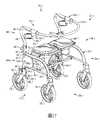
請參照各圖式,首先參照圖1,本發明顯示一高度可調式助行裝置20。此裝置具有一後端22及一前端24,從圖2可以清楚看出前端24。如圖1所示,裝置20具有一對彼此間隔之側部26、28、一頂端30、及一與頂端間隔分開之底端32。該助行裝置20之後端22及前端24係於兩側部26、28之間延伸和頂端30與底端32之間延伸。該助行裝置之頂端及底端亦在兩側部26、28之間延伸。Please refer to the drawings. First, referring to FIG. 1, the present invention shows a height-
助行裝置20包括一對彼此間隔且高度/長度可調整的直立式總成34、36,其分別與兩側部26、28之一對齊。每一直立式總成具有一下端及一上端,圖1中可見到總成34的下端38及上端40。在所示實例中,每一直立式總成為高度可調且可伸縮,並具有一位於下側的細長外構件或外管及一位於上側的細長內構件或內管,而內管之形狀設為能讓其裝配在外管內部。圖1中可見到總成34之外管42及內管44。The walking
如圖16所示,每一內管44具有複數個沿縱向分隔的小孔46,此等小孔46界定一調整範圍的長度L。助行裝置20並包括一對耦接機構,可選擇性地將各對伸縮套管42、44耦接在一起;在此一實例中,該等耦接機構為指旋螺絲(thumb screws)48之形式。在此一實例中,該等指旋螺絲係旋轉地耦接於外管42。選擇性旋轉指旋螺絲48時可使其選擇性地插入內管44的小孔46之一,以調整並固定該等伸縮套管的高度。如此能調整助行裝置20的高度,以便提供使用者最適宜的手把高度。因此,助行裝置的高度能從圖15所示的套管42、44縮入位置,調整到圖16所示的套管伸展位置以及兩者之間的其他位置。As shown in FIG. 16, each
如圖6所示,該等直立式總成34之各個外管42有一延伸的開孔51;在此一實例中,該開孔51為狹長孔(slot)形狀及長圓形(obround)。在此實例中,此等開孔係面向助行裝置20之前端24。每一開孔51設於直立式總成34的下端38與上端40之間。每一開孔鄰近於其對應之直立式總成下端38,但位於該下端上方且相隔一距離。As shown in FIG. 6, each
請再參照圖1。助行裝置20並包括一對彼此間隔的側部延伸總成50、52。該等側部延伸總成分別與該助行裝置之二側部26、28之一對齊,並從該助行裝置接近底端32之處朝其頂端30延伸。每一側部延伸總成包括一對彼此間隔的細長上、下方側構件;在此一實例中,該等上方側構件為管體54之形式,而該等下方側構件則為桿體56之形式。每一桿體具有一近端58耦接於對應的外管42,及一與該近端彼此間隔之遠端60。在此實例中,每一桿體56係垂直對應之外管42沿側部向外延伸至助行裝置20之前端24。每一桿體具有一沿縱長方向延伸之頂面61,面向其側部延伸總成50之對應管體54。如圖6所示,該等桿體之頂面至少有一部份具有曲線狀的側向截面;在此一實例中,該等桿體之頂面具有外凸之側向截面。Please refer to Figure 1 again. The walking
每一管體54包括一大致平直部62,在此一實例中,這部份係與對應的外管42耦接,並從該處沿側部朝外延伸至助行裝置20之前端24。在此一實例中,套管42的開孔51位於桿體56與管體54的大致平直部62之間並在其間延伸,且其位置較鄰近桿體56。請參照圖1,該等管體54之每一平直部62具有一沿縱長方向延伸之底面63,並面向對應桿體56之頂面61。該等管體54的平直部之底面至少有一部份具有曲線狀的側向截面;在此一實例中,該等管體平直部之底面具有外凸之側向截面。在此一實例中,每一管體54並包括一曲弧部64,該曲弧部與該管體之平直部62及對應桿體56之遠端60耦接,且位於兩者之間。Each
如圖1所示,助行裝置20包括一收摺機構66,在此一實例中,收摺機構66係耦接於側部延伸總成50、52並在其間延伸。所述收摺機構係設為能選擇性地橫向收摺該助行裝置。助行裝置20並包括一椅座總成68,在此一實例中,椅座總成68係在兩側部延伸總成50、52之管體54的平直部62之間延伸且與該等平直部耦接。關於收摺機構66及椅座總成68的各種零件與作用方式,在美國專利第8,083,239號中有更詳細的說明。As shown in FIG. 1, the walking
如圖1所示,助行裝置20包括一對第一或前端觸地轉輪70,該轉輪係利用輪叉74而活動耦接於該等管體54的曲弧部64之遠端72,並能相對該等曲弧部的遠端樞轉。所述助行裝置並包括一對第二或後端觸地轉輪,活動耦接於該等直立式總成之下端並能相對該處旋轉。圖1顯示轉輪76經由一輪叉78活動耦接於直立式總成34之下端38。As shown in FIG. 1, the walking
助行裝置20包括一對制動總成,分別配合第二對觸地轉輪之一使用,圖4顯示與轉輪76配合使用之制動總成80。The walking
如圖4所示,每一制動總成包括一觸輪制動構件82。每一觸輪制動構件具有一第一端84及一與第一端彼此間隔之第二端86。在此一實例中,每一觸輪制動構件82在一樞接點88樞接於其各自之輪叉78,而樞接點88係位於該觸輪制動構件之第一端與第二端之間。每一觸輪制動構件82包括一制動墊90;在此一實例中,制動墊90係與第一端84耦接並從該處向下延伸。每一制動墊面對與其對應之轉輪76。在此一實例中,每一觸輪制動構件82包括一彈性構件,該彈性構件之形狀如一螺旋彈簧92。螺旋彈簧以觸輪制動構件的樞接點88為中心延伸。螺旋彈簧92具有一細長端94;在此一實例中,細長端94係鄰接於輪叉78之一側壁96。該螺旋彈簧係設為能將制動墊90從轉輪76向上回彈偏置(spring-bias)。As shown in FIG. 4, each brake assembly includes a
每一觸輪制動構件82包括一第一貫孔97;在此一實例中,第一貫孔97延伸貫穿鄰近觸輪制動構件第二端86之處。每一觸輪制動構件82並包括一第二貫孔99,該貫孔之位置亦鄰近觸輪制動構件第二端86;在此一實例中,第二貫孔99係為一螺孔。在此一實例中,第二貫孔係連通第一貫孔97並以垂直第一貫孔的方向延伸。每一制動總成80並包括一緊固機構,在此一實例中,緊固機構為一固定螺絲107,其延伸貫穿貫孔99並以螺旋方式與該貫孔嚙合。Each
每一制動總成進而包括一制動纜線總成;在此一實例中,該制動纜線總成為一鮑登鋼線98。所述鮑登鋼線包括一可撓之內纜線100。如圖5所示,該內纜線具有一上端或第一端101,該端設有一突部;在此一實例中,所述突部係位於第一端之乳頭狀突部102。在此一實例中,所述乳頭狀突部呈圓柱形。如圖4所示,每一內纜線100並具有一下端或第二端103。所述內纜線之第二端係藉由延伸貫穿貫孔97之纜線端部105,活動耦接於觸輪制動構件82之第二端86,然後藉由固定螺絲107與端部105接合。固定螺絲可供調整內纜線100的張力,亦即將內纜線100的下端103下降或上升後,再經由固定螺絲將纜線緊固定位。Each brake assembly further includes a brake cable assembly; in this example, the brake cable always becomes a
如圖15所示,每一鮑登鋼線98主要是被包圍在其所對應的直立式總成34內部,並有一鬆弛部109延伸貫穿該直立式總成34的開孔51。該制動纜線總成之鬆弛部為該制動纜線總成的一截盤旋區段;在此實例中,該盤旋區段為環圈狀。As shown in FIG. 15, each
請參照圖5,每一鮑登鋼線98包括一可撓之外套管108,內纜線100延伸貫穿外套管108,並能相對外套管移動。所述外套管具有一第一端110(見圖5)及一第二端112(見圖4)。外套管108之第二端112係經由一固定座114而與輪叉78活動耦接,內纜線100則穿過固定座114延伸。在此一實例中,每一固定座為管狀,其具有由貫孔115延伸貫穿之一第一/上套筒113。每一上套筒之形狀設為可沿對應的外套管108之第二端112延伸並容置該第二端。每一固定座114並包括一第二/下套筒117,該下套筒耦接於該上套筒113並從該處朝下延伸。每一下套筒包括一貫穿其之貫孔119。貫孔119之形狀設為能供內纜線100滑動容置其內並穿過之。貫孔119與貫孔115連通;在此一實例中,貫孔119之直徑小於貫孔115之直徑。下套筒117之形狀設為能裝配在輪叉78的一個內孔121內。上套筒113設為與鄰近所述內孔121之輪叉之部位129鄰接。5, each
內纜線100的上移動作會使觸輪制動構件82的第二端86移到相對圖4較上方的位置,如箭頭122所示。內纜線100的上移動作繼而會使觸輪制動構件的第一端84及制動墊90向下移動,如箭頭123所示,使制動墊抵接轉輪76並使之煞車。因此,每一觸輪制動構件82係活動連接於對應之直立式總成34的下端38,如圖1所示。此處說明之觸輪制動構件82僅屬可供助行裝置20使用的實例之一;在其他具體實施例中,制動總成80可使用其他的制動系統配合鮑登鋼線98使用。The upward movement of the
如圖1所示,助行裝置20包括一對手把總成124、125,分別耦接於直立式總成34、36之一的上端40。該助行裝置並包括一弧形的靠背127;在此一實例中,靠背127係沿著助行裝置之前端24設置。在此一實例中,所述靠背之形狀為一可撓板體,在兩手把總成124、125之間延伸並與該等手把總成耦接在一起。As shown in FIG. 1, the walking
每一手把總成,如圖5所示的總成124,包括一第一手把槓桿126。每一第一手把槓桿具有一第一端128及一與第一端彼此間隔之第二端136。每一制動總成80包括一制動作動器;在此一實例中,該制動作動器之形式為一握把130,其耦接於對應之手把槓桿126的端部128,並從該處延伸。每一手把總成124具有一手把外殼134。每一第一手把槓桿126係經由樞軸132以可樞轉的方式安裝於手把外殼134。Each handle assembly, such as the
每一手把總成124包括一第二手把槓桿138。每一第二手把槓桿具有一第一端142、一與該第一端彼此間隔之第二端144、一面向該可撓外套管108之第一側143、及一與該第一側相反之第二側145。第二手把槓桿138之第一端142與第二端144在該槓桿之第一側143與第二側145之間延伸。每一第二手把槓桿138係經由鄰近其第一端142的樞軸140以可樞轉的方式安裝於對應的手把外殼134。第一手把槓桿126的第二端136設置為能在第二手把槓桿138之第一端142與第二端144之間的位置164,與第二手把槓桿138接合。Each
每一手把總成124包括一連桿146,該連桿經由第一手把槓桿兩端128、136之間的樞軸148以及第二手把槓桿兩端142、144之間的樞軸150,將第一手把槓桿126樞接於第二手把槓桿138。槓桿138具有一錐形孔152;在此一實例中,錐形孔152延伸貫穿槓桿138鄰近其第二端144之處。錐形孔152從槓桿138之第一側143朝槓桿138之第二側145延伸,且其位於第一側143之橫截面相對大於其位於第二側145之橫截面。換言之,錐形孔152係從槓桿138之第二側145往其第一側143放大。在此一實例中,每一槓桿138進而包括一承座153;在此一實例中,該承座具有圓形之截面且與錐形孔152連通。每一承座153鄰近於槓桿138之第二側145並相對該側成內凹。Each
內纜線100之第一端101係活動耦接於槓桿138之第二端144,因此,藉由內纜線鄰近乳頭狀突部102的區段154延伸貫穿錐形孔152,內纜線可活動連接於握把130。乳頭狀突部102大於錐形孔152,且其形狀設為能被承座153所容置。如圖1所示,兩握把130因而可活動地連接於對應的直立式總成34之上端40。請再參照圖5,錐形孔152朝外漸縮的性質使內纜線100上的區段154能夠選擇性地上下傾斜,如箭頭157所示。The
可撓外套管108的第一端110係經由一固定座156而耦接於手把外殼134,內纜線100則穿過固定座156。在此一實例中,該固定座大致為圓筒形並具有一面向可撓外套管108的第一側159,及一與該第一側相反之第二側161。在此一實例中,每一固定座156包括一承座163;在此一實例中,該承座為圓筒形並相對固定座第一側159為內凹。可撓外套管108的第一端110,其形狀設為能容置在承座163內。在此一實例中,每一固定座156包括一錐形孔165,從固定座之第二側161朝第一側159延伸。錐形孔165位於第二側161之橫截面相對大於其鄰近第一側159之橫截面。換言之,錐形孔165係從固定座156之第一側159往其第二側161放大。錐形孔165係與承座163連通。當內纜線100延伸至乳頭狀突部102時,有一區段167延伸通過錐形孔165。錐形孔165朝外漸縮的性質使內纜線100上的區段167能夠選擇性地上下傾斜,如箭頭169所示。The
請參照圖5。於操作時,握把130的上移動作,如箭頭162所示,會使第一手把槓桿126的第二端136在第二手把槓桿138之第一端142與第二端144之間的位置164,與第二手把槓桿138接合。如此會使第二手把槓桿138選擇性地以相對圖5的順時鐘方向朝助行裝置20的前端24旋轉,如箭頭166所示。第二手把槓桿138的第二端144及內纜線100的第一端101因此被推至相對圖5的右側。如此會作動內纜線100並使之相對可撓外套管108移動,以選擇性地作動觸輪制動構件82,如圖4所示。Please refer to Figure 5. During operation, the upward movement of the
請參照圖4。每一鮑登鋼線98因而具有一第一端耦接於一細長總成之第一部位;在此一實例中,該細長總成之第一部位為直立式總成34(見圖15)之觸輪制動構件82(見圖4)。請參照圖5,每一鮑登鋼線並具有一第二端與所述細長總成之第二部位耦接;其中該第二部位相對於第一部位的位置為可調整;在此一實例中,所述細長總成之第二部位為該直立式總成之手把總成124。Please refer to Figure 4. Each
圖5所示的握把130及本發明所說明的相關連桿總成僅屬於可供助行裝置20使用之一實例,在其他具體實施例中,所述制動總成80可使用其他的制動作動器配合鮑登鋼線98使用。The
迄目前為止所說明的助行裝置20僅屬助行裝置之一實例,凡熟悉此類技藝之人士當可理解,尚有其他多種可行的助行裝置形狀及架構。例如,在其他具體實施例中,亦可使用美國專利第8,083,239號及美國專利第9,339,432號中所陳述的助行裝置側部延伸總成、手把、靠背、收摺機構、轉輪總成及椅座總成。The walking
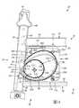
如圖1所示,助行裝置20包括一對中空的制動纜線外殼,分別對應所述直立式總成之一。圖中顯示的是直立式總成34的制動纜線外殼168。如圖14所示,每一外殼之形狀設為能包圍所對應的鮑登鋼線98的鬆弛部109。在此一實例中,每一制動纜線外殼之形狀大致為一中空的長方體(rectangular prism)。As shown in Fig. 1, the walking
如圖9所示,每一制動纜線外殼具有一細長的頂面170及一沿著該頂面延伸的上周邊部172。如圖11所示,在此一實例中,該上周邊部為u形,並以朝上方向形成一朝外的內凹狀。請參照圖14,在此一實例中,外殼168的上周邊部172之形狀設為對齊並能容置管體54之大致平直部62之底面63。As shown in FIG. 9, each brake cable housing has an elongated
如圖10所示,每一外殼168具有一個與頂面170相反的細長底面174,及一沿著該底面延伸的下周邊部176。如圖11所示,在此一實例中,下周邊部176為u形,並以朝下方向形成一朝外的內凹狀。請參照圖14,在此一實例中,外殼168的下周邊部其形狀設為與桿體56之頂面61對齊並沿頂面61的局部區段延伸與容置該段頂面61。因此,每一外殼168係在與之對應的桿體56及管體54之大致平直部62之間延伸。As shown in FIG. 10, each
請參照圖9,每一外殼168進而包括一後側178,在該外殼之頂面170與底面174之間延伸;在此一實例中,該後側之橫截面大致為u形。如圖14所示,該外殼的後側係沿著對應的直立式總成34之外管42位於管體54及桿體56之間的區段180延伸,該外殼後側之形狀並設為能鄰接及容置該區段180。Referring to FIG. 9, each
如圖9所示,每一制動纜線外殼168包括一中空突出部182,從該外殼之後側178朝外延伸。每一突出部包括一周緣部181與外殼之後側耦接並從該處朝外延伸。在此一實例中,最佳地如圖11所示,所述周緣部為長圓形。周緣部181之形狀設為能裝配於圖6所示的外管42之長橢圓形(oblong)開孔51內。請參照圖14,在此一實例中,外管42環繞長橢圓形開孔51而延伸的部位53,係設為能緊貼鄰接於該周緣部181。As shown in FIG. 9, each
如圖9所示,所述突出部182包括一下區段177;在此一實例中,所述下區段之形狀大致為直角三角形稜柱(right triangular prism)並耦接於周緣部181,且從該處朝外延伸。每一突出部182並包括一細長的底面183對齊並鄰近於外殼168之底面174。突出部182之下區段177包括一對彼此間隔之平坦側面185、187;在此一實例中,該等平坦側面大致為三角形。突出部182之二個側面從突出部的底面183朝向外殼168的頂面170延伸。如圖11所示,在此一實例中,側面185、187係朝內與外殼168的二個側面186、188彼此間隔並平行外殼二側面186、188而延伸。As shown in FIG. 9, the protruding
請參照圖9及圖11,每一突出部182包括一對彈性構件;在此一實例中,該等彈性構件之形式為分別從側面185、187之一朝外延伸的彈性突片189、191。如圖14所示,當突出部182之下區段177位於外管42之開孔51內時,該等彈性突片之形狀設為能朝外鄰接於外管42之鄰近部位55之處。9 and 11, each
請參照圖9,突出部182之下區段177包括一後側面195;在此一實例中,該後側面為斜面狀,從底面183朝周緣部181的頂端197延伸。後側面195為細長狀並在突出部下區段177的兩側面185、187之間延伸。每一突出部包括一凹孔193延伸貫穿下區段177的後側面195。所述凹孔位於該突出部之兩側面185、187及底面183之間。Referring to FIG. 9, the
如圖14所示及以上所述,突出部182之下區段177延伸貫穿對應之外管42的開孔51,藉此將制動纜線外殼168安裝於直立式總成34。因此,如圖1所示,每一制動纜線外殼168在該總成之握把130與觸輪制動構件82之間的位置,係活動地連接於對應之直立式總成34。As shown in FIG. 14 and described above, the
最佳地如圖12所示,每一外殼168具有一前側184,其與最佳地如圖11所示之後側178彼此間隔。請再參照圖12,所述外殼之前側係在外殼的頂面170與底面174之間延伸。如圖15所示,在此一實例中,外殼186的前側184大致為垂直延伸並呈平直狀。As best shown in FIG. 12, each
該等制動纜線外殼具有彼此相向之內側面,如圖8所示之外殼168之內側面186。每一外殼並包括一個與該內側面相反之外側面188。在此一實例中,外殼168之內、外側面大致為平坦的矩形,並在該外殼的頂面、底面、後側及前側之間延伸。圖9係顯示外殼168之外側面188在該外殼的頂面170、底面174、後側178及前側184之間延伸。The brake cable housings have inner sides facing each other, such as the
如圖11所示,每一制動纜線外殼168包括一第一殼部190在該外殼的頂面170、底面174、後側及前側之間延伸,並從外殼之內側面186朝外側面188延伸。如圖1所示,所述外殼之第一殼部係在桿體56及管體54的大致平直部62之間延伸並鄰接該處之第一側或內側196,如圖2所示。As shown in FIG. 11, each
如圖9所示,每一制動纜線外殼168並包括一第二殼部192與第一殼部190互補,並可選擇性地與第一殼部190接合與分開。在此一實例中,殼部190、192分別為外殼168的兩半部之一,但此並非絕對必要之條件。殼部192係在外殼168的頂面170、底面174、後側178及前側184之間延伸,並從外殼之外側面188朝內側面186延伸。在此一實例中,殼部192之形狀設為能經由如圖8所示之複數個緊固件194選擇性地耦接於殼部190。如圖1所示,殼部192係在桿體56及管體54的大致平直部62之間延伸並鄰接該處之第二側或外側198。藉此,制動纜線外殼168選擇性地耦接於助行裝置20之對應的側部延伸總成50。As shown in FIG. 9, each
如圖14所示,每一制動纜線外殼168具有一內部空間200;在此一實例中,該內部空間大致為新月形。每一制動纜線外殼並具有一外框部202沿著外殼的頂面170、底面174、後側178及前側184之間延伸,同時,如圖11所示,並在外殼之兩側面186、188之間延伸。如圖14所示,該外殼之外框部202具有一內周邊204;內周邊204沿外殼的兩側面包圍該內部空間200。在此一實例中,所述外框部之內周邊係呈內凹形且大致為淚滴狀。在此一實例中,所述外殼之外框部202具有一中央軸線206。As shown in FIG. 14, each
每一外殼168並包括一內框部208位於內部空間200之中。所述外殼之內框部具有一外周邊210;在此一實例中,所述外周邊呈外凸形。外殼168之內框部208具有一中央軸線212;中央軸線212於軸向上從該外殼外框部202之中央軸線206偏置。Each
如圖14所示,制動纜線外殼168將鮑登鋼線98之鬆弛部109收容在其內部空間200內。所述制動纜線外殼之內部空間中包括一上通道214。所述上通道從鄰近開孔51之外殼後側178朝外殼頂面170及前側184延伸。在此一實例中,上通道214係呈朝下之內凹狀。所述上通道之形狀設為能容置鮑登鋼線98延伸自觸輪制動構件82(亦即圖4所示內纜線100之下端103)的過多區段216。As shown in FIG. 14, the
請再參照圖14,制動纜線外殼168之內部空間200中並包括一下通道218。在此一實例中,突出部182之下區段177之凹孔193為下通道218的一部份。因此,在此一實例中,下通道218係穿過外殼168的突出部182並延伸至外殼的底面174及前側184。在此一實例中,下通道218係呈朝上之內凹狀。下通道218之形狀係設為能容置鮑登鋼線98從圖5所示握把130(亦即內纜線100之上端101)延伸的過多區段220。Please refer to FIG. 14 again, the
如圖14所示,每一制動纜線外殼168於其內部空間200中包括一容室222。該容室位於上、下通道214、218之間並與該等通道連通。所述上通道與下通道二者的斷面寬度呈漸縮狀,因此當該等通道從直立式總成34往容室222延伸時,其寬度漸增。從圖中可以看出,通道218鄰近外管42之處的寬度W1小於通道218鄰近容室222之處的寬度W2。所述容室之形狀設為能容置鮑登鋼線98的額外過多區段224,該鮑登鋼線98與該等過多區段216、220耦接且形成一體。在此一實例中,容室222為面向上通道214及下通道218呈內凹狀。分別相較於上通道214及下通道218二者之一,該容室的容積及斷面寬度W3皆較大。As shown in FIG. 14, each
操作狀態請參照圖15。當助行裝置20在其縮入位置時,鮑登鋼線98之鬆弛部109係鄰接於對應之外殼168的外框部202的內周邊204。如圖14所示,當助行裝置20在圖15所示之縮入位置及圖16所示之伸展位置之間的中間位置時,鮑登鋼線98之鬆弛部109至少有局部係在外殼168之內框部208的外周邊210及該外殼之外框部202的內周邊204之間延伸。Please refer to Figure 15 for operating status. When the walking
如圖16所示,當助行裝置20在其伸展位置時,鮑登鋼線98之鬆弛部109係鄰接於對應之外殼168的內框部208的外周邊210。相較於助行裝置20在圖16所示伸展位置時之鮑登鋼線98鬆弛部109所形成的環圈尺寸,助行裝置20在圖15所示縮入位置時之鮑登鋼線98鬆弛部109所形成的環圈尺寸較大。As shown in FIG. 16, when the walking
圖17顯示根據本發明第二實施例之高度可調式助行裝置20.1。其中與圖1至圖16所示高度可調式助行裝置20相似之部件,其功能均相似,並使用相似標號但增加小數點副標號“.1”。助行裝置20.1大致與圖1-16所示的助行裝置20相同,但有以下例外。在此一實例中,每一外殼168.1的前側184.1係朝助行裝置20.1之前端24.1呈外凸狀,與圖1所示外殼168大致呈垂直延伸的平直狀前側184有所不同。Fig. 17 shows a height-adjustable walking aid 20.1 according to a second embodiment of the present invention. Among them, the components similar to the height-
附加說明Additional information
以上已說明用於高度可調式助行裝置之制動總成的若干實例。本發明提供以下各項作為進一步的說明。Several examples of brake assemblies used in height-adjustable walking aids have been described above. The present invention provides the following items as further explanation.
(1)一種制動纜線外殼之形狀設為能包圍該制動纜線總成之一鬆弛部;該外殼具有一內部空間並包括一外框部;該外殼之外框部具有一內周邊包圍所述內部空間,且該外殼外框部之內周邊呈內凹狀;該外殼並包括一內框部位於該內部空間中,且該外殼內框部具有一外凸狀之外周邊。(1) A brake cable housing is shaped to surround a slack portion of the brake cable assembly; the housing has an inner space and includes an outer frame; the outer frame of the housing has an inner periphery Said internal space, and the inner periphery of the outer frame of the shell is concave; the shell also includes an inner frame located in the internal space, and the inner frame of the shell has a convex outer periphery.
(2)一種用於助行裝置之制動纜線外殼;該助行裝置能從一縮入位置調整為一伸展位置;當助行裝置在所述伸展位置時,其制動纜線總成係鄰接於該外殼一內框部之外周邊;而當助行裝置在所述縮入位置時,該制動纜線總成係鄰接於該外殼一外框部之內周邊。(2) A brake cable housing for a walking device; the walking device can be adjusted from a retracted position to an extended position; when the walking device is in the extended position, the brake cable assembly is adjacent to On the outer periphery of an inner frame of the housing; and when the walking aid is in the retracted position, the brake cable assembly is adjacent to the inner periphery of an outer frame of the housing.
(3)一種配合鮑登鋼線使用之纜線外殼;所述鮑登鋼線具有一第一端耦接於一助行裝置的第一細長構件,及一第二端耦接於該助行裝置上的第二細長構件;該第二細長構件相對於該第一細長構件之位置為可調整;該外殼之形狀設為能包圍鮑登鋼線位於所述第一端與第二端之間的一個環圈形區段。(3) A cable housing for use with Bowden steel wire; said Bowden steel wire has a first end coupled to a first elongated member of a walking device, and a second end coupled to a second device on the walking device An elongated member; the position of the second elongated member relative to the first elongated member is adjustable; the shape of the shell is set to surround a loop-shaped section of the Bowden wire between the first end and the second end .
(4)如第3項所述之外殼,該鮑登鋼線之第一端為一上端,該鮑登鋼線之第二端為一下端;其中該外殼包括一上通道、一下通道及一容室;該上通道之形狀設為能容置鮑登鋼線延伸自該下端的區段,下通道之形狀設為能容置鮑登鋼線延伸自該上端的區段,而該容室與所述二通道相連通。(4) The housing as described in item 3, the first end of the Bowden steel wire is an upper end, and the second end of the Bowden steel wire is a lower end; wherein the housing includes an upper channel, a lower channel and a chamber; the The shape of the upper channel is set to accommodate the section of the Bowden wire extending from the lower end, the shape of the lower channel is set to accommodate the section of the Bowden wire extending from the upper end, and the chamber is communicated with the two channels.
(5)結合論之,第3及第4項中任一項所述之纜線外殼與鮑登鋼線;所述鮑登鋼線包括一可撓外套管與一可撓內纜線,該外套管之第一端與第二端分別耦接於助行裝置之第一細長構件與第二細長構件,該內纜線延伸貫穿該外套管並能相對外套管移動。(5) In combination, the cable housing and Bowden steel wire described in any one of items 3 and 4; the Bowden steel wire includes a flexible outer tube and a flexible inner cable. One end and the second end are respectively coupled to the first elongated member and the second elongated member of the walking aid, and the inner cable extends through the outer tube and can move relative to the outer tube.
(6)一種用於高度可調式助行裝置之制動總成;該制動總成包括一制動作動器;該制動總成包括一觸輪制動構件;該制動總成包括一制動纜線總成,所述制動纜線總成包括一可撓的內纜線及一可撓的外套管,該內纜線延伸貫穿該外套管並能相對外套管移動,該內纜線具有與該制動作動器耦接的第一端以及與該觸輪制動構件耦接的第二端;該制動總成並包括一個如第1至第4項中任一項所述之制動纜線外殼。(6) A brake assembly for a height-adjustable mobility aid; the brake assembly includes a brake actuator; the brake assembly includes a trolley brake member; the brake assembly includes a brake cable assembly, The brake cable assembly includes a flexible inner cable and a flexible outer tube. The inner cable extends through the outer tube and can move relative to the outer tube. The inner cable is coupled to the brake actuator. The first end is connected and the second end is coupled to the trolley brake member; the brake assembly also includes a brake cable housing as described in any one of items 1 to 4.
(7)一種助行裝置包括如第1至第6項中任一項所述之纜線外殼。(7) A walking aid device comprising the cable housing as described in any one of items 1 to 6.
此處所述發明之範圍內,可有多種變化。凡具有此類技藝之人士當可理解,以上所提供的細節,有許多部份僅為舉例說明而非用以限制本發明之範圍,本發明範圍應參照至少以下申請專利範圍決定之。Many variations are possible within the scope of the invention described here. Anyone with such skills should understand that many of the details provided above are merely illustrative and not intended to limit the scope of the present invention. The scope of the present invention should be determined with reference to at least the scope of the following patent applications.
20:高度可調式助行裝置20: Height-adjustable walking device
22:後端22: backend
24:前端24: front end
26:側部26: side
28:側部28: side
30:頂端30: top
32:底端32: bottom
34:高度/長度可調整的直立式總成34: Vertical assembly with adjustable height/length
36:高度/長度可調整的直立式總成36: Vertical assembly with adjustable height/length
40:上端40: upper end
42:外管42: Outer tube
44:內管44: inner tube
48:指旋螺絲48: Thumbscrew
50:側部延伸總成50: Side extension assembly
52:側部延伸總成52: Side extension assembly
54:上方側構件(管體)54: Upper side member (pipe body)
56:下方側構件(桿體)56: Lower side member (rod body)
58:桿體近端58: Proximal pole
60:桿體遠端60: The distal end of the shaft
61:桿體頂面61: The top surface of the shaft
62:管體大致平直部62: The roughly straight part of the tube body
63:管體沿縱長方向延伸之底面63: The bottom surface of the tube extending in the longitudinal direction
64:管體曲弧部64: the curved part of the tube body
66:收摺機構66: Folding mechanism
68:椅座總成68: Chair seat assembly
70:第一或前端觸地轉輪70: The first or front-end ground contact runner
72:曲弧部遠端72: The distal end of the arc
74:輪叉74: Wheel fork
76:第二或後端觸地轉輪76: second or rear ground contact runner
78:輪叉78: wheel fork
80:制動總成80: Brake assembly
82:觸輪制動構件82: trolley brake component
84:觸輪制動構件第一端84: The first end of the trolley brake member
124:手把總成124: Handle Assembly
125:手把總成125: Handle Assembly
127:靠背127: Backrest
130:握把130: grip
168:制動纜線外殼168: Brake cable housing
170:外殼之細長頂面170: The slender top surface of the shell
174:外殼之細長底面174: The slender bottom of the shell
188:外殼之外側面188: Outer shell side
190:外殼第一殼部190: The first shell part of the outer shell
198:管體及桿體之第二側或外側198: The second side or outer side of the tube body and the rod body
Claims (20)
Translated fromChineseApplications Claiming Priority (4)
| Application Number | Priority Date | Filing Date | Title |
|---|---|---|---|
| US201562213566P | 2015-09-02 | 2015-09-02 | |
| US62/213,566 | 2015-09-02 | ||
| US14/966,572 | 2015-12-11 | ||
| US14/966,572US10053062B2 (en) | 2015-09-02 | 2015-12-11 | Brake assembly for a height-adjustable walker apparatus |
Publications (2)
| Publication Number | Publication Date |
|---|---|
| TW201711663A TW201711663A (en) | 2017-04-01 |
| TWI725047Btrue TWI725047B (en) | 2021-04-21 |
Family
ID=58097344
Family Applications (1)
| Application Number | Title | Priority Date | Filing Date |
|---|---|---|---|
| TW105127319ATWI725047B (en) | 2015-09-02 | 2016-08-25 | Brake assembly for a height-adjustable walker apparatus and walker apparatus |
Country Status (6)
| Country | Link |
|---|---|
| US (1) | US10053062B2 (en) |
| EP (1) | EP3344210B1 (en) |
| JP (1) | JP6781247B2 (en) |
| CN (1) | CN108135770B (en) |
| TW (1) | TWI725047B (en) |
| WO (1) | WO2017035633A1 (en) |
Families Citing this family (15)
| Publication number | Priority date | Publication date | Assignee | Title |
|---|---|---|---|---|
| US9381132B2 (en) | 2013-12-23 | 2016-07-05 | Bdark Holdings Ltd. | Walkers and methods of use |
| US10730489B2 (en) | 2015-09-02 | 2020-08-04 | Evolution Technologies Inc. | Brake assembly for height-adjustable patient transport apparatus |
| US11648922B2 (en) | 2015-09-02 | 2023-05-16 | Evolution Technologies Inc. | Manually-operated, height-adjustable wheeled vehicle, and a brake assembly and wheel fork assembly thereof |
| US10966896B2 (en)* | 2015-12-17 | 2021-04-06 | Maple Leaf Medical Services Llc | Rollator braking system |
| JP2018164532A (en)* | 2017-03-28 | 2018-10-25 | アロン化成株式会社 | Walking car |
| US11259984B2 (en)* | 2017-08-03 | 2022-03-01 | Medline Industries, Lp | Reciprocating rollator |
| FI12337U1 (en)* | 2018-04-09 | 2019-04-15 | Ksv Finland Llc | Mobility aid |
| WO2020051518A1 (en)* | 2018-09-07 | 2020-03-12 | Stander Inc. | Collapsible walking device |
| WO2020205578A1 (en) | 2019-03-29 | 2020-10-08 | Darling June, PBC | Walker apparatus |
| USD976162S1 (en) | 2019-04-02 | 2023-01-24 | Darling June, Pbc. | Walker apparatus |
| USD906901S1 (en)* | 2019-04-02 | 2021-01-05 | Darling June, PBC | Walker apparatus |
| US12090115B2 (en) | 2019-09-30 | 2024-09-17 | Evolution Technologies Inc. | Cable tension adjuster for height-adjustable wheeled vehicle |
| CN215558134U (en)* | 2021-06-18 | 2022-01-18 | 厦门基信医疗技术有限公司 | Folding capable ware brake line take-up that helps |
| CN114135607A (en)* | 2021-12-02 | 2022-03-04 | 王春红 | Parking device for wheelchair |
| USD1047784S1 (en)* | 2024-03-06 | 2024-10-22 | Eliana Delatorre | Rollator |
Citations (5)
| Publication number | Priority date | Publication date | Assignee | Title |
|---|---|---|---|---|
| US4029311A (en)* | 1975-05-01 | 1977-06-14 | Hal Chanslor | Invalid walker with brakes |
| US5268986A (en)* | 1991-09-09 | 1993-12-07 | Sumitomo Electric Industries, Ltd. | Redundant length treatment mechanism for optical fiber at terminal of optical cable |
| US6378663B1 (en)* | 2000-11-01 | 2002-04-30 | Apex Medical Corp. | Brake mechanism for a walker |
| TWM426403U (en)* | 2011-10-12 | 2012-04-11 | Jin-Cang Wu | Walk-assisting vehicle with safety device |
| TW201507718A (en)* | 2013-03-15 | 2015-03-01 | Amg Medical Inc | A mobile support assembly |
Family Cites Families (316)
| Publication number | Priority date | Publication date | Assignee | Title |
|---|---|---|---|---|
| US534443A (en) | 1895-02-19 | Combined blacking-case and chair | ||
| US291351A (en) | 1884-01-01 | jackson | ||
| US522117A (en) | 1894-06-26 | Phrey | ||
| US188835A (en) | 1877-03-27 | Improvement in perambulators | ||
| US2732047A (en) | 1956-01-24 | Finkelstein | ||
| US879803A (en) | 1907-10-09 | 1908-02-18 | Charles Joseph Vlasak | Combined chair and cabinet. |
| GB191223483A (en) | 1912-11-15 | 1913-05-01 | Thomas Morgan | A Friction Brake for Perambulators & the like. |
| US1767925A (en) | 1928-06-16 | 1930-06-24 | Hargreaves Thomas | Combined seat and carrier |
| DE551058C (en) | 1929-10-04 | 1932-05-25 | Thilo Kipping | Braking device for vehicles, in particular motor vehicles |
| US2169860A (en) | 1937-02-12 | 1939-08-15 | Gen Electric | Guard means for electric switches |
| US2483307A (en) | 1946-06-20 | 1949-09-27 | Wheary Inc | Suitcase handle having transparent plastic grip and u-shaped metal core |
| US2631655A (en) | 1947-01-28 | 1953-03-17 | Jannello Cesar Victorino | Chair |
| US2656881A (en) | 1950-07-24 | 1953-10-27 | Bertis F Hamilton | Metal furniture |
| US2681809A (en) | 1950-12-30 | 1954-06-22 | Raymond L Hamill | Combined seat and tote box for fishermen's use |
| US2710084A (en) | 1954-02-23 | 1955-06-07 | Irving L Braverman | Traveling bags |
| US2812227A (en) | 1955-08-29 | 1957-11-05 | Hill Amelia | Combined hassock and bar |
| US2864466A (en) | 1955-09-08 | 1958-12-16 | Webb H C & Co Ltd | Brakes for cycles |
| US2866495A (en) | 1956-06-05 | 1958-12-30 | Invalid Walker & Wheel Chair C | Invalid folding walker and chair |
| US3018506A (en) | 1958-05-09 | 1962-01-30 | Haydock Raymond | Caster insert socket |
| US2987149A (en) | 1959-01-26 | 1961-06-06 | Philadelphia Handle Company In | Luggage handle |
| US2937248A (en) | 1959-02-27 | 1960-05-17 | Ite Circuit Breaker Ltd | Circuit breaker handle lock |
| AT214095B (en) | 1960-03-11 | 1961-03-10 | Sykora & M Prokop H | Bed bench or double bed bench |
| US3061049A (en) | 1960-07-18 | 1962-10-30 | William S West | Braking system |
| US3109899A (en) | 1960-10-18 | 1963-11-05 | Cutler Hammer Inc | Handle lock |
| US3142351A (en) | 1962-01-19 | 1964-07-28 | Canadian Res | Stair climbing wheelchair |
| US3194577A (en) | 1962-03-22 | 1965-07-13 | Berlin Daniel | Combination baby walker and jumper |
| AT242315B (en) | 1962-11-30 | 1965-09-10 | Rogelio Raichs Mill | Multi-part handle or handle for vessels of all kinds |
| GB984025A (en) | 1963-01-03 | 1965-02-24 | Tan Sad Ltd | Improvements relating to brakes for invalid chairs, perambulators and the like |
| US3268965A (en) | 1964-05-11 | 1966-08-30 | Lisle Corp | Cable clamp |
| US3376400A (en) | 1965-03-10 | 1968-04-02 | Square D Co | Handle locking attachment for electrical control devices |
| US3288250A (en) | 1965-07-08 | 1966-11-29 | Oja | Braking means for mobile devices |
| US3409105A (en) | 1967-06-21 | 1968-11-05 | Stewart Warner Corp | Caster assembly |
| US3692155A (en) | 1970-10-22 | 1972-09-19 | Lark Luggage Corp | Handle assembly |
| CH534061A (en) | 1971-01-20 | 1973-02-28 | Tente Rollen Gmbh & Co | Caster, in particular a swivel castor, with a locking device |
| US3690652A (en) | 1971-06-07 | 1972-09-12 | Parker Machine Co Inc | Foldable invalid walker convertible from fixed to swingable walker |
| DE2220095A1 (en) | 1972-04-24 | 1973-11-08 | Happe & Co | SWIVEL CASTOR WITH LOCKING LEVER TO BLOCK THE PIVOTING AND ROTATING MOBILITY OF YOUR WHEEL |
| US3903944A (en) | 1973-07-18 | 1975-09-09 | Cannondale Corp | Fabric utility bag |
| US3927727A (en) | 1974-04-17 | 1975-12-23 | Corbin Gentry Inc | Vehicular seat and fairing assembly |
| JPS5410282Y2 (en) | 1975-07-25 | 1979-05-12 | ||
| US3969964A (en) | 1975-09-02 | 1976-07-20 | Douglas Franklin George | Hand tool for holding an elongated member while simultaneously moving a second member axially along the elongated member |
| US4056115A (en) | 1976-05-06 | 1977-11-01 | Thomas Morton I | Adapter for manipulating a spring loaded pushbutton |
| US4084663A (en) | 1976-08-30 | 1978-04-18 | Frederick Haley | Automatic brake for wheeled carriages |
| US4087141A (en) | 1976-09-03 | 1978-05-02 | General Electric Company | Door pull handle assembly |
| US4149721A (en) | 1977-05-09 | 1979-04-17 | Strickland Gordon E | Replaceable grip piece for racket |
| US4184618A (en) | 1977-05-26 | 1980-01-22 | Jones Marjorie F | Article carrying attachment for walkers |
| JPS5545191Y2 (en) | 1977-08-05 | 1980-10-23 | ||
| SE430377B (en) | 1978-12-06 | 1983-11-14 | Ilon B E | DEVICE WHICH HAS STANDED SHOWING A WHEEL-SUPPORTED SUPER |
| US4286401A (en) | 1979-04-23 | 1981-09-01 | Pachmayr Gun Works, Inc. | Cushioned gun grip |
| US4325561A (en) | 1980-03-17 | 1982-04-20 | Lynn Gary S | Nesting patient transport tables |
| US4384713A (en) | 1980-05-28 | 1983-05-24 | White Cap Enterprises Corporation | Safety rolling invalid walker |
| US4351540A (en) | 1980-11-13 | 1982-09-28 | Quadra Wheelchairs, Inc. | Wheelchair construction |
| US4415198A (en) | 1980-11-18 | 1983-11-15 | Brearley Gordon D | Seat for invalid walker |
| US4371183A (en) | 1980-12-22 | 1983-02-01 | Dion Jean Paul | Folding wheel-chair |
| US4462138A (en) | 1981-05-04 | 1984-07-31 | Pemco-Kalamazoo, Inc. | Wheel bracket assembly having a resilient element with progressively increasing resistance |
| DE3119649C2 (en) | 1981-05-16 | 1987-03-19 | Tente-Rollen Gmbh & Co, 5632 Wermelskirchen | Castor with a locking device |
| US4404822A (en)* | 1981-05-18 | 1983-09-20 | Green Leonard O | Pre-coiled cable-lock device |
| US4494271A (en) | 1981-11-30 | 1985-01-22 | Perlin Materials Handling Development Co. | Caster having a three piece encapsulating bearing assembly |
| US4493488A (en) | 1982-02-16 | 1985-01-15 | Panaia David J | Pressure control wheel chair seat |
| US4460188A (en) | 1982-04-15 | 1984-07-17 | Maloof John J | Cart with seat and storage compartment |
| US4449750A (en) | 1982-09-09 | 1984-05-22 | Pultman Martin D | Accessories for wheelchairs and the like |
| US4509662A (en) | 1983-01-13 | 1985-04-09 | Weiss Sherman L | Caulking gun |
| US4572409A (en) | 1983-05-02 | 1986-02-25 | Gary Finnegan | Drip free caulking gun |
| US4570370A (en) | 1984-03-12 | 1986-02-18 | Smith Alan K | Wide angled gun magazine entrance guide opening |
| US4596484A (en) | 1984-10-05 | 1986-06-24 | Velbon International Corporation | Lock for telescoping tubular support |
| US4761092A (en) | 1984-10-05 | 1988-08-02 | Koma Nakatani | Lock for telescoping tubular leg |
| JPH0735762Y2 (en) | 1984-12-30 | 1995-08-16 | 日産自動車株式会社 | Swivel caster |
| US4800991A (en) | 1985-08-19 | 1989-01-31 | Miller Nicholas A | Brake maintenance monitor |
| DE3531824A1 (en) | 1985-09-06 | 1987-03-19 | Tente Rollen Gmbh & Co | STEERING WHEEL |
| GB2180508A (en) | 1985-09-18 | 1987-04-01 | Mullin And Company Limited | A portable container trolley |
| US4659099A (en) | 1986-03-24 | 1987-04-21 | Charlotte Malone | Food and item tray for a walker and a wheelchair |
| US4676416A (en) | 1986-06-06 | 1987-06-30 | Harmon Carol A | Walker and carrier therefor |
| US4740010A (en) | 1987-01-09 | 1988-04-26 | Accurate Metal Products, Inc. | Foldable cart |
| US4765644A (en) | 1987-01-20 | 1988-08-23 | Bell Laurence G | Foldable cart |
| US4800911A (en) | 1987-04-06 | 1989-01-31 | Endres Kathleen O | Walker carrier |
| US4830035A (en) | 1987-05-13 | 1989-05-16 | Liu Antony Ching Fong | Seesawly-controlled foldable walker |
| US4856123A (en) | 1987-09-24 | 1989-08-15 | Henderson Medical Appliance Company Ltd. | Toilet apparatus for use by bed ridden patients |
| US4853500A (en)* | 1987-12-11 | 1989-08-01 | Wyle Laboratories | Jamfree cable storage |
| US4907794A (en) | 1987-12-24 | 1990-03-13 | Guardian Products, Inc. | Foldable rolling walker |
| JP2536627Y2 (en) | 1988-09-13 | 1997-05-21 | コンビ 株式会社 | Shopping cart for baby carriage |
| US4907839A (en) | 1988-10-11 | 1990-03-13 | Guardian Products, Inc. | Walker with folding seat |
| US4883317A (en) | 1988-10-17 | 1989-11-28 | Davenport Lizzie B | Multi-purpose chair |
| US4890355A (en) | 1988-10-26 | 1990-01-02 | Schulten Elizabeth W | Releasably mountable hand grip for handles |
| US4913452A (en) | 1989-06-05 | 1990-04-03 | Zun Hong Fu | Caster-supporting device for a baby stroller |
| JPH0730621Y2 (en)* | 1989-09-11 | 1995-07-12 | アルプス電気株式会社 | Cable reel for telescopic steering device of vehicle |
| US5012963A (en) | 1989-09-29 | 1991-05-07 | Patricia Rosenbaum | Walker support tote bag |
| US4974760A (en) | 1989-12-21 | 1990-12-04 | Miller Patricia H | Article carrier for a walker |
| US4962781A (en) | 1989-12-26 | 1990-10-16 | Kanbar Maurice S | Collapsible rolling cane |
| US5052075A (en) | 1990-01-11 | 1991-10-01 | Babcock Industries Inc. | Apparatus and method for securing a caster to an object having a hole |
| US5046748A (en) | 1990-04-06 | 1991-09-10 | Oat Judge Patricia C | Walker with automatic braking mechanism |
| US5020560A (en) | 1990-08-17 | 1991-06-04 | Rob Turbeville | Walker having wheels and brakes |
| US5103530A (en) | 1990-09-28 | 1992-04-14 | Century Products Company | Hub and wheel assembly with shock absorber |
| SE468621B (en) | 1990-10-23 | 1993-02-22 | Etac Ab | HANDBROMS CARRIES A WHEEL-SET TOOL, SUCH AS A ROLLATOR |
| US5167048A (en) | 1991-05-10 | 1992-12-01 | Medical Composite Technology | Caster wheel retention device |
| US5109569A (en) | 1991-07-26 | 1992-05-05 | Eastman Kodak Company | Non-oscillating caster |
| US5158313A (en) | 1991-08-12 | 1992-10-27 | Becker Sharon L | Wheeled walker |
| JP2624916B2 (en) | 1991-08-28 | 1997-06-25 | 株式会社シマノ | Caliper brake and unit type connecting member |
| JP3065799B2 (en)* | 1991-09-09 | 2000-07-17 | 住友電気工業株式会社 | Optical fiber extra length processing mechanism in optical cable terminal |
| US5188139A (en) | 1991-11-08 | 1993-02-23 | Garelick Mfg. Co. | Foldable support device |
| SE500410C2 (en) | 1992-03-24 | 1994-06-20 | Ergotek I Smaland Ab | Walking trolley hand brake control - has normal application and release positions plus mechanism to hold on brake if lever is pushed downwards |
| US5340005A (en) | 1992-05-21 | 1994-08-23 | Woods Robert D | Fabric accessories for crutches and walkers, providing carrying expandable volumes for personal use items and shopping items, and presenting reflective fabric portions thereof for observation by others |
| US5380034A (en) | 1992-09-11 | 1995-01-10 | Love Lift, L.P. | Wheelchair with convertible seat-stretcher |
| US5269157A (en) | 1992-10-13 | 1993-12-14 | Michael Ciminelli | Insulated beach box with utility attachments |
| US5356237A (en) | 1992-12-17 | 1994-10-18 | Sung Jung T | Expandable handles of walk-aiding wheeled frame |
| US5390393A (en) | 1993-01-22 | 1995-02-21 | Metro Industries, Inc. | Caster with a fouling-resistant bearing cup feature |
| US5594974A (en) | 1993-02-03 | 1997-01-21 | James P. Wattron | Releasable caster |
| US5348336A (en) | 1993-02-09 | 1994-09-20 | Fernie Geoffrey R | Walking aid |
| US5417234A (en) | 1993-02-17 | 1995-05-23 | Trek Medical Corporation | Crutch |
| US5294027A (en) | 1993-02-25 | 1994-03-15 | Bel-Art Products, Inc. | Portable combination table top/basket apparatus |
| US5364137A (en) | 1993-04-05 | 1994-11-15 | Safe-Strap Company, Inc. | Infant highchair |
| US5429377A (en) | 1993-04-15 | 1995-07-04 | Duer; Sandra D. | Sanitary protective covers for shopping cart use |
| US5465986A (en) | 1993-05-24 | 1995-11-14 | Macrae; Elwyn F. | Wheel restraining device for a shopping cart or a portable vehicle |
| DE4328875C1 (en) | 1993-08-27 | 1995-02-16 | Gregor Horacek | Collapsible walking aid |
| US5779118A (en) | 1993-09-23 | 1998-07-14 | Douglass; Karl J. | Attachable container particularly suited for ambulatory aids |
| US6189914B1 (en) | 1993-10-01 | 2001-02-20 | Worth Pfaff Innovations, Inc. | Folding stroller |
| US5605345A (en) | 1993-10-21 | 1997-02-25 | Brookefield Hunter Incorporated | Wheeled apparatus for use as walker and wheelchair |
| US5622404A (en) | 1993-10-26 | 1997-04-22 | Premier Marine, Inc. | Combination seat and storage system |
| US5433235A (en) | 1993-11-12 | 1995-07-18 | Guardian Products, Inc. | Foldable and lockable walker |
| US5353824A (en) | 1993-12-14 | 1994-10-11 | Woods Carlton M | Bifold seat for folding walker |
| GB2284768B (en) | 1993-12-17 | 1997-11-26 | David Hart | Lower limb co-ordination walking aid |
| DE4412603C2 (en) | 1994-04-13 | 1996-06-05 | Tente Rollen Gmbh & Co | Locking device for castors, in particular swivel castors |
| US5553754A (en) | 1994-06-30 | 1996-09-10 | Z-Pro International, Inc. | Caulk gun |
| US5662342A (en) | 1994-07-21 | 1997-09-02 | Clares Merchandise Handling Equipment Ltd. | Wheeled trolley |
| US5475896A (en) | 1994-08-09 | 1995-12-19 | Hua Peng Limited Co. | Furniture handle |
| US5551413A (en) | 1994-09-13 | 1996-09-03 | Hoyt Usa | Archery bow handle riser with replaceable grip heel |
| US5499697A (en) | 1994-09-15 | 1996-03-19 | Trimble; Willard R. | Shopping cart automatic dual brake |
| JP2638750B2 (en) | 1994-10-13 | 1997-08-06 | リョービ株式会社 | Power tool handle structure |
| US5700053A (en) | 1994-10-27 | 1997-12-23 | Downing; David | Cushioning and protection apparatus for a chair armrest |
| US5531238A (en) | 1995-01-31 | 1996-07-02 | Azzarelli; Paul T. | Attachment apparatus for a walker caddy container |
| US5915712A (en) | 1995-05-23 | 1999-06-29 | Stephenson; John Thomas | Removable handles for mounting on the handles of a wheelchair |
| US5692762A (en) | 1995-06-26 | 1997-12-02 | Invacare Corporation | Walker with glide assembly |
| US5687984A (en) | 1995-08-02 | 1997-11-18 | Samuel; Violet S. | Collapsing cart |
| US5639052A (en) | 1995-08-14 | 1997-06-17 | Chrysler Corporation | Flexible cupholder |
| US5632362A (en) | 1995-08-15 | 1997-05-27 | Rockshox, Inc. | Bicycle disc brake |
| US5775352A (en) | 1995-10-23 | 1998-07-07 | Invacare Corporation | Cam lock assembly for adjustable cane |
| JPH09123915A (en) | 1995-11-02 | 1997-05-13 | Junzaburo Kawasaki | Shopping cart |
| US5664460A (en) | 1995-11-13 | 1997-09-09 | Foreign Developments Limited | Cable controller |
| US5621997A (en) | 1996-01-29 | 1997-04-22 | Pearce Grip, Inc. | Handgun grip enhancer |
| US5722717A (en) | 1996-03-08 | 1998-03-03 | Rettenberger; Randy C. | Portable seat with storage compartment |
| NZ332619A (en) | 1996-05-02 | 2000-05-26 | Burgoo Holdings Ltd | Application of grips to handles |
| US6079894A (en) | 1996-06-13 | 2000-06-27 | Invacare Corporation | Integral snap button and anti-rattle member |
| US5813582A (en) | 1997-01-14 | 1998-09-29 | Wright; Joi Henderson | Adjustable shopping basket for wheelchairs |
| US5816650A (en) | 1997-02-21 | 1998-10-06 | Lear Corporation | Underseat storage bin for motor vehicles |
| DE19711730C2 (en) | 1997-03-20 | 2000-10-19 | Sig Schweiz Industrieges | Handle for a firearm |
| SE512103C2 (en) | 1997-04-01 | 2000-01-24 | Sven E Malmstroem | BRAKE MECHANISM |
| JPH10291401A (en) | 1997-04-18 | 1998-11-04 | Takagi Sansho:Kk | Fork for caster |
| AUPO672397A0 (en) | 1997-05-09 | 1997-06-05 | Bagnall, John William | Wheeled walking frame with brakes |
| US5896779A (en) | 1997-08-01 | 1999-04-27 | Sunrise Medical Hhg Inc. | Dual mode brake actuator for walker |
| GB2328495A (en) | 1997-08-20 | 1999-02-24 | Apex Medical Corp | Braking structure for a rehabilitation trolley |
| US5772234A (en) | 1997-09-23 | 1998-06-30 | Luo; Chung-I | Configuring frame of walker |
| US5927441A (en) | 1997-09-23 | 1999-07-27 | Luo; Chung-I | Braking device for trolley |
| US5865065A (en) | 1997-10-01 | 1999-02-02 | Valentine International Limited | Hand brake for a wheeled walker |
| US6082468A (en) | 1998-04-20 | 2000-07-04 | Snap-On Tools Company | Interchangeable grips for power hand tools |
| US6467785B2 (en) | 1998-07-20 | 2002-10-22 | Tony Toppses | Wheelchair with adjustable seat |
| US6047439A (en) | 1998-10-16 | 2000-04-11 | Emerson Power Transmission Corp. | Caster wheel with releasable bearing assembly |
| US6135475A (en) | 1998-10-16 | 2000-10-24 | Brown; Richard | Portable wheelchair |
| DE29818710U1 (en) | 1998-10-21 | 1999-09-02 | Thüringer Institut für Akademische Weiterbildung e.V., 99084 Erfurt | Support and baby carrier |
| JP2999761B1 (en) | 1998-11-05 | 2000-01-17 | ウチヱ株式会社 | Folding walker |
| DE19854365C2 (en) | 1998-11-25 | 2000-12-14 | Baumeister & Ostler Gmbh Co | Storage device for a cargo space of a motor vehicle |
| SE9804254L (en) | 1998-12-08 | 2000-05-22 | Liko Research And Dev Ab | Device for hand-operated brake |
| US6079290A (en) | 1999-02-02 | 2000-06-27 | Li; Charles | Rollator braking device |
| US6142526A (en) | 1999-02-16 | 2000-11-07 | Katz; David L. | Speed control pole for in-line skating |
| US6202502B1 (en) | 1999-04-27 | 2001-03-20 | Genemax Medical Products Industry Corp. | Brake mechanism for auxiliary walker |
| US6311708B1 (en) | 1999-05-27 | 2001-11-06 | Kaye Products, Inc. | Foldable walker |
| US6164154A (en)* | 1999-06-17 | 2000-12-26 | Teleflex Incorporated | Adjustable pedal with cable assembly |
| US6098487A (en) | 1999-06-25 | 2000-08-08 | Frank Fang | Hand brake for a wheeled walker |
| US6296261B1 (en) | 1999-07-12 | 2001-10-02 | Degoma Rolando I | Brake assisted steering system for a wheeled bed |
| US6371142B1 (en) | 1999-07-19 | 2002-04-16 | Tubular Fabricators Industry | Seated walker |
| US6032765A (en) | 1999-08-09 | 2000-03-07 | Larmine Manufacturing Corp. | Brake control device for a wheeled walker |
| US6216825B1 (en) | 1999-08-16 | 2001-04-17 | Chih-Cheng Hung | Brake mechanism |
| DE29914681U1 (en) | 1999-08-21 | 2000-12-28 | Tente-Rollen GmbH & Co, 42929 Wermelskirchen | Swivel castor |
| US6196562B1 (en) | 1999-08-25 | 2001-03-06 | Yu-Lin Zhuang | Push device of a stroller |
| US6192772B1 (en) | 1999-09-03 | 2001-02-27 | Shih-Yi Huang | Controller for the brake of a rolling walkkit |
| TW455489B (en) | 1999-10-12 | 2001-09-21 | Takano Co Ltd | Rolling walker |
| US6161896A (en) | 1999-10-13 | 2000-12-19 | Daimlerchrysler Corporation | Automotive vehicle rear seat storage system |
| US6409196B1 (en) | 1999-11-22 | 2002-06-25 | Mcfarland Ryan J. | Wheelchair front fork |
| US6769701B1 (en) | 1999-12-03 | 2004-08-03 | The Fairhaven Group, Inc. | Shock-absorbing wheel assemblies for luggage bag |
| US6318392B1 (en) | 2000-01-06 | 2001-11-20 | Scott Chen | Supportive walker with safety features |
| CA2396636C (en) | 2000-01-06 | 2007-12-18 | Joannes Stefanus Van't Schip | A rolling aid for use by elderly and disabled people |
| US6378883B1 (en) | 2000-01-11 | 2002-04-30 | Aaron J. Epstein | Motorized walker/wheelchair and method |
| US6347777B1 (en) | 2000-02-01 | 2002-02-19 | Hoist Fitness Systems | Seat adjustment apparatus |
| TW553332U (en) | 2000-03-28 | 2003-09-11 | Chiung-Mei Huang | Improved alignment apparatus for retractable supporting shaft |
| US6338493B1 (en) | 2000-04-19 | 2002-01-15 | Eli Wohlgemuth | Walker chair |
| DE10021151B4 (en) | 2000-04-29 | 2010-07-15 | Volkswagen Ag | Storage system for vehicles |
| CA2410919C (en) | 2000-06-05 | 2008-01-29 | Creative Action, Inc. | Foldable utility cart with lift mechanism |
| WO2001094081A1 (en) | 2000-06-07 | 2001-12-13 | Irega, S.A. | Exchangeable handle for the handles of monkey wrenches |
| US6354619B1 (en) | 2000-06-14 | 2002-03-12 | Jeong Ki Kim | Portable and collapsible carts |
| US6338355B1 (en) | 2000-06-22 | 2002-01-15 | Merits Health Products Co., Ltd. | Safety brake type rollator |
| US6386575B1 (en) | 2000-08-10 | 2002-05-14 | Convaid Products, Inc. | Mobile seat arrangement |
| US6296263B1 (en) | 2000-08-22 | 2001-10-02 | Theodore L. Schultz | Wheeled triple leg walker folding tray |
| US6340168B1 (en) | 2000-08-25 | 2002-01-22 | Doris W. Alexander | Convertible chair and walker assembly |
| US6491318B1 (en) | 2000-08-29 | 2002-12-10 | Tamara Lyn Galt | Folding cart |
| CA2329485C (en) | 2000-12-21 | 2004-08-03 | Random Products Trust | Walker with moveable carry basket |
| ATE376822T1 (en) | 2000-09-12 | 2007-11-15 | Random Products Trust | WALKER |
| US7219906B2 (en) | 2000-09-12 | 2007-05-22 | Random Products In Trust | Height-adjustable cordless brake |
| CA2507724C (en) | 2000-09-12 | 2011-03-15 | Random Products Trust | Brake handle assembly for walker |
| US20030010368A1 (en) | 2000-10-10 | 2003-01-16 | Mackinnon John Dan | Pull handle for invalid walkers |
| US7980415B2 (en) | 2000-10-30 | 2011-07-19 | Crawley Timothy M | Apparatus for replacing gripping member on wire bucket handle |
| US6442797B1 (en) | 2000-11-07 | 2002-09-03 | Link Treasure Limited | Flexible transmission device |
| US6527136B1 (en) | 2000-11-22 | 2003-03-04 | Pro-Mart Industries, Inc. | Collapsible hamper & handle |
| US6502280B2 (en) | 2000-12-13 | 2003-01-07 | Satco, Inc. | Lightweight high capacity industrial caster |
| US20020093160A1 (en) | 2001-01-12 | 2002-07-18 | Andrew Mendenhall | Juvenile stroller with portable cooler |
| US6595530B2 (en) | 2001-03-29 | 2003-07-22 | American Healthcare Solutions, Inc. | Medical walker |
| GB2377734A (en) | 2001-07-17 | 2003-01-22 | Far Great Plastics Ind Co Ltd | Scooter hand and/or foot applied arcuate braking plate having a felt |
| US6655702B2 (en) | 2002-01-15 | 2003-12-02 | Patent Holding Company | Combination vehicle passenger seat/child stroller |
| US6622587B1 (en)* | 2002-02-07 | 2003-09-23 | David Wu | Wheeled walker brake lever mounting arrangement |
| CN2551232Y (en) | 2002-05-21 | 2003-05-21 | 东莞上安鸿运动器材厂 | A car for the elderly that helps the elderly to walk and provides them with a rest |
| US6877519B2 (en) | 2002-05-29 | 2005-04-12 | Daniel J. Fink | Collapsible side wheeled walker |
| US7231689B2 (en) | 2002-06-05 | 2007-06-19 | Sunrise Medical Hhg Inc. | Adjustable wheel assembly |
| US6729342B2 (en) | 2002-06-05 | 2004-05-04 | Dr. K Healthcare Products, Inc. | Walker with release mechanism |
| US7353566B2 (en) | 2002-06-05 | 2008-04-08 | Sunrise Medical Hhg Inc. | Adjustable wheel assembly |
| US6755285B1 (en) | 2002-08-16 | 2004-06-29 | David Wu | Wheeled walker brake lever mounting structure |
| AU2003259355A1 (en) | 2002-08-28 | 2004-03-19 | Castor Technology Ltd | Improvements in or relating to castors |
| ATE367287T1 (en) | 2002-09-12 | 2007-08-15 | Johnson Controls Tech Co | FLOOR CONSOLE |
| JP4425560B2 (en) | 2002-09-24 | 2010-03-03 | コンビ株式会社 | stroller |
| GB0224644D0 (en) | 2002-10-23 | 2002-12-04 | Urquhart Dykes & Lord | A castor |
| US6773059B2 (en) | 2002-11-19 | 2004-08-10 | Dmitriy Volotsenko | Convertible device for sitting |
| US6837503B2 (en) | 2002-12-03 | 2005-01-04 | Nova Ortho-Med, Inc. | Folding walker with removable back rest |
| US6892421B2 (en) | 2002-12-11 | 2005-05-17 | The United States Of America As Represented By The Department Of Veterans Affairs | Oblique angled suspension caster fork for wheelchairs |
| US6647825B1 (en) | 2003-01-17 | 2003-11-18 | Ching-Hsu Lin | Hand brake device |
| USD501432S1 (en) | 2003-01-20 | 2005-02-01 | R82 A/S | Walker for disabled children |
| NL1022512C1 (en) | 2003-01-28 | 2004-08-03 | Robertus Johannes Barnhoorn | Inwardly foldable rollator is for persons with walking problems, helping them to stand and walk, being equipped with two L-shaped side arms, each with horizontal leg |
| US6921101B1 (en) | 2003-02-07 | 2005-07-26 | Givi Lauren | Combined wheelchair, walker, and sitting chair |
| SE522197C2 (en) | 2003-02-24 | 2004-01-20 | Dolomite Ab | Rollator, has brake part for wheel connected to control on handle via upper and lower transmission devices linked via coupling device |
| US6817066B1 (en) | 2003-03-20 | 2004-11-16 | Kenneth Williams | Handle grip apparatus |
| US6886575B2 (en) | 2003-03-25 | 2005-05-03 | Medical Depot, Inc. | Lock release mechanism for foldable walkers |
| US7052030B2 (en) | 2003-07-02 | 2006-05-30 | Medical Depot | Wheeled walker |
| EP1660005A1 (en) | 2003-08-25 | 2006-05-31 | Craig E. Karasin | Walker |
| JP2005087415A (en) | 2003-09-16 | 2005-04-07 | Swany Corp | Stick-cum-wheelchair |
| US20050121481A1 (en) | 2003-09-22 | 2005-06-09 | Chiu Johnny J. | Walker basket |
| US6886216B2 (en) | 2003-09-30 | 2005-05-03 | Component Hardware Group, Inc. | Caster leg assembly with adjustment locking means |
| NO318777B1 (en) | 2003-09-30 | 2005-05-02 | Access As | A height-adjustable walker with a brake |
| US20080129016A1 (en) | 2006-01-31 | 2008-06-05 | Phillip Minyard Willis | Mobile support assembly |
| US7926834B2 (en) | 2003-10-07 | 2011-04-19 | AMG Medical, USA | Mobile support assembly |
| US6810560B1 (en) | 2003-11-06 | 2004-11-02 | Hai-Ming Tsai | Castor |
| US20050156395A1 (en) | 2004-01-20 | 2005-07-21 | Bohn David L. | Rolling walker with arm rest platforms |
| US7290742B2 (en) | 2004-03-19 | 2007-11-06 | Wang Dennis H | Adjustable support tool for vertical and horizontal mounting |
| US7108004B2 (en) | 2004-03-26 | 2006-09-19 | Random Products In Trust | Mobility aiding device |
| US7278436B2 (en) | 2004-04-26 | 2007-10-09 | Cosco Management, Inc. | Adjustable walker |
| US20050250605A1 (en) | 2004-05-07 | 2005-11-10 | Tubular Fabricators Industry, Inc. | Replaceable grip handle |
| EP1761143B1 (en) | 2004-05-17 | 2014-05-28 | Orbit Baby, Inc. | Actively securable base for a modular child restraint system |
| DE202004010326U1 (en) | 2004-07-01 | 2004-11-11 | Wang, Chu-Yu | Position adjusting system for telescopic tubes comprises tubular sleeve which fits over them and carries spring-loaded lever with latch which cooperates with slots in inner tube through aperture in outer tube |
| US7211744B2 (en) | 2004-07-09 | 2007-05-01 | Hubbell Incorporated | Snap-in cable connector |
| US7243666B2 (en) | 2004-07-20 | 2007-07-17 | Carroll Donald K | Walker including supports for carrying oxygen bottles |
| US7422550B1 (en) | 2004-09-20 | 2008-09-09 | Michelle Pinero | Gait trainer |
| US7384058B2 (en) | 2005-01-05 | 2008-06-10 | Ki Mobility Llc | Foldable wheelchair with extensible link assembly and method |
| US20060156511A1 (en) | 2005-01-19 | 2006-07-20 | Li Yuan J | Caster |
| EP2017156A3 (en) | 2005-01-21 | 2010-02-10 | Graco Children's Products Inc. | Stroller |
| DE102005016020A1 (en) | 2005-04-07 | 2006-10-12 | Heckler & Koch Gmbh | Firearm handle and kit with change parts for this |
| SE528513C2 (en) | 2005-04-20 | 2006-12-05 | Volaris Sweden Ab | Braking device for walker and walker including brake device |
| US7445216B1 (en) | 2005-05-24 | 2008-11-04 | Eht Worldwide Co., Ltd. | Multifunctional handcart |
| US7500689B2 (en) | 2005-11-09 | 2009-03-10 | Peter Pasternak | Wheelchair attachments |
| EP1792750A1 (en) | 2005-12-05 | 2007-06-06 | Invacare International Sàrl | Removable wheel support device for a wheelchair |
| US20070278271A1 (en) | 2005-12-21 | 2007-12-06 | Joe Koren | Walker support tote bag |
| FR2895702B1 (en) | 2005-12-29 | 2008-02-29 | Bruandet Sa Sa | ROULETTE FOR FURNITURE OR THE LIKE |
| US7306246B2 (en) | 2006-01-19 | 2007-12-11 | Gale Bradley D | Highly collapsible ambulatory assistive walker apparatus |
| CN2875405Y (en) | 2006-01-26 | 2007-03-07 | 佛山市南海建泰铝制品有限公司 | Folding walking-aid cart |
| US7451992B2 (en) | 2006-01-31 | 2008-11-18 | Phillip Minyard Willis | Mobile support assembly |
| US20070199586A1 (en) | 2006-02-24 | 2007-08-30 | Juei-Chuan Cheng | Lock assembly of foldable walker |
| US20070235067A1 (en) | 2006-03-30 | 2007-10-11 | Cosco Management, Inc. | Rolling walker |
| US20070227570A1 (en) | 2006-03-30 | 2007-10-04 | Cosco Management, Inc. | Adult Walker Lock-Release Apparatus |
| US7828305B2 (en) | 2006-05-17 | 2010-11-09 | Amg Medical Inc. | Rolling walker and handle grips thereof |
| US20070278768A1 (en) | 2006-06-01 | 2007-12-06 | Lynam Timothy B | System combining a foldable wheeled cart and removable cloth bag |
| US20070283990A1 (en) | 2006-06-12 | 2007-12-13 | Fernandez Felix L | Convertible wheelchair and walker |
| AU2007284006A1 (en) | 2006-08-18 | 2008-02-21 | Querine Pty Ltd | A wheeled walker |
| US7494138B2 (en) | 2006-09-25 | 2009-02-24 | Gary Graham | Bipedal motion assisting method and apparatus |
| US7628438B2 (en) | 2006-10-23 | 2009-12-08 | Ford Global Technologies, Llc | Rear seat cushion underside storage flap |
| US7628411B2 (en) | 2006-10-24 | 2009-12-08 | Amg Medical Inc. | Height adjustable rolling walker for transportation seating |
| US20080121258A1 (en) | 2006-11-28 | 2008-05-29 | Mei Ru Lin | Walker with folding seat |
| US7743779B2 (en) | 2007-01-19 | 2010-06-29 | Gee Sr Larry Ellis | Crutch stroller |
| CN201500997U (en) | 2007-02-01 | 2010-06-09 | 永备电池有限公司 | Razor handle |
| US7837205B2 (en) | 2007-03-05 | 2010-11-23 | Cari-All Products Inc. | Shopping cart and collapsible compartment thereof |
| US7587852B1 (en) | 2007-05-25 | 2009-09-15 | Ccf Raceframes Llc | Handgun grip with a removable and replaceable grip portion |
| US7841257B2 (en) | 2007-06-11 | 2010-11-30 | Grand Rapids Controls Company, Llc | Compensator for cables |
| US8511694B2 (en) | 2007-08-01 | 2013-08-20 | Scott N. Bradshaw | Reversible walker assembly |
| WO2009126892A2 (en) | 2008-04-10 | 2009-10-15 | Stander Inc | Collapsible walking device |
| US8313066B2 (en) | 2008-06-25 | 2012-11-20 | Medline Industries, Inc. | Intravenous fluid container stand and methods for making same |
| US8157273B2 (en) | 2008-08-17 | 2012-04-17 | Amir Bar-Lev | Adjustable stroller |
| US8936256B2 (en) | 2008-10-08 | 2015-01-20 | Evolution Technologies Inc. | Foldable walker apparatus |
| US8083239B2 (en) | 2008-10-08 | 2011-12-27 | Evolution Technologies Inc. | Foldable walker apparatus |
| US9022413B2 (en) | 2008-10-08 | 2015-05-05 | Evolution Technologies Inc. | Foldable walker apparatus |
| US8602424B2 (en) | 2008-10-08 | 2013-12-10 | Evolution Technologies, Inc. | Foldable walker apparatus |
| US8020679B2 (en) | 2009-03-16 | 2011-09-20 | Chen-Chuan Wu | Rotatable foot-wheel used for luggage trunk |
| US8434171B2 (en) | 2009-04-09 | 2013-05-07 | Free 2 Go Producs | Commode seat for a rollator |
| US7984724B1 (en) | 2009-05-04 | 2011-07-26 | Eric Eberle | Rolling walking support with a utility bag having interchangeable front panels providing alert indicia |
| US20110241303A1 (en) | 2009-05-07 | 2011-10-06 | Campbell Ronald B | Walkers with improved handles |
| US8646804B2 (en) | 2009-05-29 | 2014-02-11 | Medline Industries, Inc. | Apparatus for a convertible wheeled patient aid |
| US8002363B2 (en) | 2009-08-26 | 2011-08-23 | Pao-Hsien Cheng | Quick release structure for front wheel of baby stroller |
| US20110146027A1 (en) | 2009-12-22 | 2011-06-23 | Po-Chuan Tsai | Castor Assembly Having Adjustable Height |
| US8167351B2 (en) | 2010-01-06 | 2012-05-01 | Plowman Donald J | Seat/flatbed/drop-in-container assembly for cart |
| US8490311B2 (en) | 2010-01-11 | 2013-07-23 | Hogue, Inc. | Firearm grip sleeve with retention feature |
| US20110187067A1 (en) | 2010-02-01 | 2011-08-04 | Staggs Gary M | Shower chair/walker combination |
| US8480100B2 (en) | 2010-02-01 | 2013-07-09 | Gary M. Staggs | Shower chair/walker combination |
| DE102010031954A1 (en) | 2010-07-22 | 2012-01-26 | Bischoff & Bischoff Medizin- Und Rehabilitationstechnik Gmbh | Walking frame for use as continuous supporter by walking impaired person, during walking, has seat surface formed by foldable seat board, and foldable cross beam arranged under seat board, which lies on cross beam in folded apart condition |
| USD697163S1 (en) | 2010-09-08 | 2014-01-07 | Michael B. Bietsch | Handgun grip insert |
| GB201015390D0 (en) | 2010-09-15 | 2010-10-27 | Icandy World Ltd | A vehicle frame assembly |
| EP2618796A1 (en) | 2010-09-23 | 2013-07-31 | Hazeleger Investments B.V. | Assist device with standing aid for adding to a wheelchair, a wheelchair integrated with such an assist device and method for manufacture thereof |
| US20120084940A1 (en) | 2010-10-07 | 2012-04-12 | Po-Chuan Tsai | Castor Having a Greater Structural Strength to Bear a Heavier Load |
| US9221433B2 (en)* | 2010-10-18 | 2015-12-29 | Thomas F. Dunlap | Safety braking system for a hand-pushed rollator |
| US8505936B2 (en) | 2010-10-29 | 2013-08-13 | Evolution Technologies Inc. | Foldable walker apparatus |
| US8573613B2 (en) | 2010-10-29 | 2013-11-05 | Evolution Technologies Inc. | Foldable walker apparatus |
| US9415635B2 (en) | 2010-10-29 | 2016-08-16 | Evolution Technologies Inc. | Foldable walker apparatus |
| DE202011003227U1 (en) | 2011-02-22 | 2012-02-27 | Boris Schulmann | Compact lightweight folding walker as walker device |
| CN202061329U (en) | 2011-05-11 | 2011-12-07 | 源民安企业股份有限公司 | Racket with replaceable grip |
| EP2537503B9 (en) | 2011-06-23 | 2015-01-21 | Invacare International Sàrl | Foldable seat for a rollator or a wheelchair |
| CN202163565U (en)* | 2011-07-21 | 2012-03-14 | 易扬波 | Rollator brake locking device |
| TWM424944U (en) | 2011-09-09 | 2012-03-21 | Miao-Yuan Huang | Easily-foldable walking-aid vehicle |
| CN102512310B (en) | 2011-12-21 | 2013-09-18 | 武汉科技大学 | Foldable multifunctional rollator |
| CN202490148U (en) | 2012-03-07 | 2012-10-17 | 佛山市东方医疗设备厂有限公司 | Wheeled walker with variable wheelchair |
| GB2502873B (en) | 2012-04-10 | 2018-11-07 | Wonderland Switzerland Ag | Tandem stroller with detachable height-adjustable rear seat |
| AU2013341540B2 (en) | 2012-11-06 | 2018-03-01 | Medline Industries, Inc. | Improved rollator |
| US8801073B1 (en) | 2013-03-06 | 2014-08-12 | Ford Global Technologies, Llc | Luggage retention system |
| US9180065B2 (en) | 2013-04-15 | 2015-11-10 | Evolution Technologies Inc. | Foldable walker apparatus |
| DE102013217906B3 (en)* | 2013-09-09 | 2014-12-24 | Schaeffler Technologies Gmbh & Co. Kg | Braking device for walking aids |
| US9022397B1 (en) | 2013-10-09 | 2015-05-05 | Raymon Earl Prettyman | Adapter system for walker |
| CN203544058U (en) | 2013-10-09 | 2014-04-16 | 巫锦沧 | Fixtures for adjusting the telescoping frame |
| US9339432B2 (en) | 2014-02-28 | 2016-05-17 | Evolution Technologies Inc. | Walker apparatus and backrest therefor |
- 2015
- 2015-12-11USUS14/966,572patent/US10053062B2/enactiveActive
- 2016
- 2016-08-19CNCN201680050840.6Apatent/CN108135770B/enactiveActive
- 2016-08-19EPEP16840452.3Apatent/EP3344210B1/enactiveActive
- 2016-08-19JPJP2018511673Apatent/JP6781247B2/enactiveActive
- 2016-08-19WOPCT/CA2016/050978patent/WO2017035633A1/ennot_activeCeased
- 2016-08-25TWTW105127319Apatent/TWI725047B/enactive
Patent Citations (5)
| Publication number | Priority date | Publication date | Assignee | Title |
|---|---|---|---|---|
| US4029311A (en)* | 1975-05-01 | 1977-06-14 | Hal Chanslor | Invalid walker with brakes |
| US5268986A (en)* | 1991-09-09 | 1993-12-07 | Sumitomo Electric Industries, Ltd. | Redundant length treatment mechanism for optical fiber at terminal of optical cable |
| US6378663B1 (en)* | 2000-11-01 | 2002-04-30 | Apex Medical Corp. | Brake mechanism for a walker |
| TWM426403U (en)* | 2011-10-12 | 2012-04-11 | Jin-Cang Wu | Walk-assisting vehicle with safety device |
| TW201507718A (en)* | 2013-03-15 | 2015-03-01 | Amg Medical Inc | A mobile support assembly |
Also Published As
| Publication number | Publication date |
|---|---|
| JP6781247B2 (en) | 2020-11-04 |
| EP3344210A1 (en) | 2018-07-11 |
| CN108135770A (en) | 2018-06-08 |
| CN108135770B (en) | 2021-01-19 |
| EP3344210A4 (en) | 2019-03-27 |
| EP3344210B1 (en) | 2021-09-01 |
| US20170057473A1 (en) | 2017-03-02 |
| JP2018529054A (en) | 2018-10-04 |
| US10053062B2 (en) | 2018-08-21 |
| TW201711663A (en) | 2017-04-01 |
| WO2017035633A1 (en) | 2017-03-09 |
Similar Documents
| Publication | Publication Date | Title |
|---|---|---|
| TWI725047B (en) | Brake assembly for a height-adjustable walker apparatus and walker apparatus | |
| US7992584B1 (en) | Walker with retractable wheels | |
| US7780183B2 (en) | Single-hand-operated actuating mechanism for a foldable stroller | |
| AU648467B2 (en) | Collapsible golf cart | |
| US7841353B2 (en) | Foldable walking stick with adjustable length and a shock-proofing mechanism | |
| US20060237934A1 (en) | Collapsible skateboard | |
| JP2021536345A (en) | Foldable walking device | |
| JP5810530B2 (en) | Walker with adjustable handle | |
| TWM264185U (en) | Handle | |
| US10730489B2 (en) | Brake assembly for height-adjustable patient transport apparatus | |
| US8876125B1 (en) | Frame apparatus for lightweight rollator | |
| US11648922B2 (en) | Manually-operated, height-adjustable wheeled vehicle, and a brake assembly and wheel fork assembly thereof | |
| EP2777677A1 (en) | A mobile support assembly | |
| US20050227836A1 (en) | Push-up trainer | |
| JP2013022287A (en) | Walking aid | |
| JP4833580B2 (en) | Rotating puller structure | |
| EP2777669A1 (en) | A mobile support assembly | |
| JP2004090734A (en) | Handlebar height adjustment mechanism for barrow | |
| CA2940154C (en) | Brake assembly for a height-adjustable walker apparatus | |
| JP2006341670A (en) | Caster | |
| WO2018209421A1 (en) | Three- wheeled walker | |
| US6932746B2 (en) | Jumping stick | |
| TW200938181A (en) | Multi-stage stair/slope walker | |
| KR200360646Y1 (en) | kick board | |
| JP5457926B2 (en) | Grounding member jumping mechanism for welfare equipment and carry cart incorporating the same |