TWI724946B - Key - Google Patents
KeyDownload PDFInfo
- Publication number
- TWI724946B TWI724946BTW109124351ATW109124351ATWI724946BTW I724946 BTWI724946 BTW I724946BTW 109124351 ATW109124351 ATW 109124351ATW 109124351 ATW109124351 ATW 109124351ATW I724946 BTWI724946 BTW I724946B
- Authority
- TW
- Taiwan
- Prior art keywords
- key cap
- protruding structures
- protruding
- connecting member
- keycap
- Prior art date
Links
- 230000000994depressogenic effectEffects0.000claimsdescription16
- 239000000758substrateSubstances0.000abstract2
- 238000010586diagramMethods0.000description26
- 238000012360testing methodMethods0.000description5
- 238000013461designMethods0.000description4
- 238000013459approachMethods0.000description2
- 238000012552reviewMethods0.000description2
- 238000006073displacement reactionMethods0.000description1
- 230000000694effectsEffects0.000description1
- 239000002184metalSubstances0.000description1
- 238000012986modificationMethods0.000description1
- 230000004048modificationEffects0.000description1
- 238000012545processingMethods0.000description1
- 230000000750progressive effectEffects0.000description1
Images


Classifications
- H—ELECTRICITY
- H01—ELECTRIC ELEMENTS
- H01H—ELECTRIC SWITCHES; RELAYS; SELECTORS; EMERGENCY PROTECTIVE DEVICES
- H01H13/00—Switches having rectilinearly-movable operating part or parts adapted for pushing or pulling in one direction only, e.g. push-button switch
- H01H13/70—Switches having rectilinearly-movable operating part or parts adapted for pushing or pulling in one direction only, e.g. push-button switch having a plurality of operating members associated with different sets of contacts, e.g. keyboard
- H01H13/702—Switches having rectilinearly-movable operating part or parts adapted for pushing or pulling in one direction only, e.g. push-button switch having a plurality of operating members associated with different sets of contacts, e.g. keyboard with contacts carried by or formed from layers in a multilayer structure, e.g. membrane switches
- H01H13/705—Switches having rectilinearly-movable operating part or parts adapted for pushing or pulling in one direction only, e.g. push-button switch having a plurality of operating members associated with different sets of contacts, e.g. keyboard with contacts carried by or formed from layers in a multilayer structure, e.g. membrane switches characterised by construction, mounting or arrangement of operating parts, e.g. push-buttons or keys
- H01H13/7065—Switches having rectilinearly-movable operating part or parts adapted for pushing or pulling in one direction only, e.g. push-button switch having a plurality of operating members associated with different sets of contacts, e.g. keyboard with contacts carried by or formed from layers in a multilayer structure, e.g. membrane switches characterised by construction, mounting or arrangement of operating parts, e.g. push-buttons or keys characterised by the mechanism between keys and layered keyboards
- H—ELECTRICITY
- H01—ELECTRIC ELEMENTS
- H01H—ELECTRIC SWITCHES; RELAYS; SELECTORS; EMERGENCY PROTECTIVE DEVICES
- H01H3/00—Mechanisms for operating contacts
- H01H3/02—Operating parts, i.e. for operating driving mechanism by a mechanical force external to the switch
- H01H3/12—Push-buttons
- H01H3/122—Push-buttons with enlarged actuating area, e.g. of the elongated bar-type; Stabilising means therefor
- H01H3/125—Push-buttons with enlarged actuating area, e.g. of the elongated bar-type; Stabilising means therefor using a scissor mechanism as stabiliser
- H—ELECTRICITY
- H01—ELECTRIC ELEMENTS
- H01H—ELECTRIC SWITCHES; RELAYS; SELECTORS; EMERGENCY PROTECTIVE DEVICES
- H01H2221/00—Actuators
- H01H2221/062—Damping vibrations
Landscapes
- Electrophonic Musical Instruments (AREA)
Abstract
Description
Translated fromChinese本創作係有關於一種按鍵,特別是指一種降低擊鍵噪音的按鍵。This creation is about a button, especially a button that reduces the noise of keystrokes.
應用於鍵盤上的按鍵,主要通過剪刀連接組件所構成的架構,來將按鍵之鍵帽與其底板作活動連結。現有剪刀連接組件因按壓按鍵時,剪刀上表面會與按鍵內側面撞擊而產生響聲,尤其在快速擊鍵時,聲響尤其明顯,噪音影響他人。The keys applied to the keyboard are mainly connected with the structure formed by the scissors connecting components to connect the keycaps of the keys with their bottom plates. In the prior art scissors connection assembly, when the key is pressed, the upper surface of the scissors will collide with the inner side of the key to produce a sound, especially when the key is pressed quickly, the sound is particularly pronounced, and the noise affects others.
本創作一實施例係提供一種按鍵,包括底板、鍵帽、連接組件及複數突出結構體。鍵帽位於底板上。連接組件包括位於底板與鍵帽之間之第一連接件及第二連接件,第一連接件一端連接於底板,另一端連接於鍵帽,第二連接件一端連接於底板,另一端連接於鍵帽。複數突出結構體設置於第一連接件之上表面、以及/或者設置於第二連接件之上表面,各突出結構體面向於鍵帽之底面。按壓鍵帽至下壓位置時,鍵帽之底面接觸於複數突出結構體,複數突出結構體頂開於鍵帽使鍵帽與連接組件之間形成有空隙。An embodiment of the present invention provides a key including a bottom plate, a key cap, a connecting component and a plurality of protruding structures. The key cap is located on the bottom plate. The connecting assembly includes a first connecting piece and a second connecting piece located between the bottom plate and the key cap. One end of the first connecting piece is connected to the bottom plate, the other end is connected to the key cap, one end of the second connecting piece is connected to the bottom plate, and the other end is connected to keycap. The plurality of protruding structures are arranged on the upper surface of the first connecting member and/or on the upper surface of the second connecting member, and each of the protruding structures faces the bottom surface of the key cap. When the key cap is pressed to the depressed position, the bottom surface of the key cap contacts the plurality of protruding structures, and the plurality of protruding structures protrude from the key cap to form a gap between the key cap and the connecting component.
在一些實施例中,各突出結構體以點、線或面接觸於鍵帽之底面。In some embodiments, each protruding structure contacts the bottom surface of the key cap with a point, a line, or a surface.
在一些實施例中,複數突出結構體為弧形結構、圓錐結構、球結構、圓柱結構或長條肋結構。In some embodiments, the plurality of protruding structures is an arc structure, a conical structure, a spherical structure, a cylindrical structure, or a long rib structure.
在一些實施例中,第一連接件包括內框型本體,第二連接件包括外框型本體,複數突出結構體分別設置於內框型本體之複數側臂的上表面、以及/或者設置於外框型本體之複數側臂的上表面。In some embodiments, the first connecting member includes an inner frame type body, the second connecting member includes an outer frame type body, and the plurality of protruding structures are respectively disposed on the upper surface of the plurality of side arms of the inner frame type body, and/or The upper surface of the plural side arms of the outer frame type body.
在一些實施例中,按壓鍵帽至下壓位置時,第一連接件及第二連接件橫向設置且非平行。In some embodiments, when the keycap is pressed to the depressed position, the first connecting member and the second connecting member are arranged laterally and non-parallel.
在一些實施例中,第一連接件另一端的兩側各設有第一上軸部,第二連接件另一端的兩側各設有第二上軸部,複數第一上軸部與複數第二上軸部分別組接於鍵帽之複數樞孔與複數倒勾。In some embodiments, both sides of the other end of the first connecting member are provided with first upper shaft portions, and both sides of the other end of the second connecting member are provided with second upper shaft portions. The second upper shaft part is respectively assembled and connected to the plural pivot holes and plural undercuts of the key cap.
在一些實施例中,複數突出結構體分別設置於相鄰第一上軸部之第一連接件的上表面、以及/或者設置於相鄰第二上軸部之第二連接件的上表面。In some embodiments, the plurality of protruding structures are respectively arranged on the upper surface of the first connecting member of the adjacent first upper shaft portion and/or on the upper surface of the second connecting member of the adjacent second upper shaft portion.
在一些實施例中,突出結構體設置於第一連接件另一端,突出結構體之中心點與第一上軸部之中心點為相同中心點設置或不同中心點設置。In some embodiments, the protruding structure is disposed at the other end of the first connecting member, and the center point of the protruding structure and the center point of the first upper shaft portion are set at the same center point or set at different center points.
在一些實施例中,突出結構體設置於第二連接件另一端,突出結構體之中心點與第二上軸部之中心點為相同中心點設置或不相同中心點設置。In some embodiments, the protruding structure is disposed at the other end of the second connecting member, and the center point of the protruding structure and the center point of the second upper shaft are set at the same center point or not at the same center point.
在一些實施例中,鍵帽至上頂位置時,鍵帽之底面接觸於複數突出結構體,複數突出結構體接觸於鍵帽使鍵帽與複數突出結構體之間的連接處無間隙。In some embodiments, when the key cap reaches the top position, the bottom surface of the key cap contacts the plurality of protruding structures, and the plurality of protruding structures contacts the key cap so that there is no gap between the connection between the key cap and the plurality of protruding structures.
在一些實施例中,鍵帽由上頂位置至下壓位置時,鍵帽之底面持續接觸於複數突出結構體之弧形結構表面。In some embodiments, when the keycap moves from the top position to the depressed position, the bottom surface of the keycap continuously contacts the arc structure surface of the plurality of protruding structures.
本創作一實施例在按壓鍵帽至下壓位置時,第一連接件與第二連接件上的複數突出結構體頂住鍵帽之底面,複數突出結構體頂開於鍵帽使鍵帽與連接組件之間形成有空隙,鍵帽之底面無法碰觸第一連接件的上表面與第二連接件的上表面,避免面接觸面所產生的撞擊音,得以消除噪音。另外,鍵帽至上頂位置時,鍵帽之底面接觸於複數突出結構體,使鍵帽與複數突出結構體之間的連接處無間隙,得以消除噪音。In an embodiment of this invention, when the key cap is pressed to the down position, the plurality of protruding structures on the first connecting piece and the second connecting piece bear against the bottom surface of the key cap, and the plurality of protruding structures are opened on the key cap to make the key cap and A gap is formed between the connecting components, and the bottom surface of the key cap cannot touch the upper surface of the first connecting piece and the upper surface of the second connecting piece, avoiding the impact sound generated by the surface contacting surface and eliminating noise. In addition, when the keycap reaches the top position, the bottom surface of the keycap is in contact with the plurality of protruding structures, so that there is no gap between the key cap and the plurality of protruding structures, and noise can be eliminated.
以下在實施方式中詳細敘述本創作之詳細特徵以及優點,其內容足以使任何熟習相關技藝者瞭解本創作之技術內容並據以實施,且根據本說明書所揭露之內容、申請專利範圍及圖式,任何熟習相關技藝者可輕易地理解本創作相關之目的及優點。The detailed features and advantages of this creation will be described in detail in the following implementations. The content is sufficient to enable anyone familiar with the relevant art to understand the technical content of this creation and implement it accordingly, and based on the content disclosed in this specification, the scope of patent application and the drawings. , Anyone who is familiar with relevant skills can easily understand the purpose and advantages of this creation.
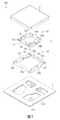
參照圖1及圖2,為按鍵的實施例,圖1為正面分解示意圖,圖2為背面分解示意圖。本實施例中,按鍵100包括底板1、鍵帽2、連接組件3及複數突出結構體4。1 and FIG. 2 are embodiments of the button, FIG. 1 is an exploded schematic view of the front, and FIG. 2 is an exploded schematic view of the back. In this embodiment, the
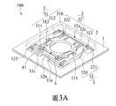
參照圖1至圖3A,圖3A為按壓時之外觀示意圖。本實施例中,底板1用於承載鍵帽2、連接組件3或其它各組件(例如彈性體(如橡膠圓頂、金屬圓頂或彈片),圖未示)。鍵帽2相對位於底板1上方,並通過連接組件3而設置於底板1上。更詳細地說,底板1可由底層與電路層所構成,電路層具有一導通部以供鍵帽2在被按壓後作導通,進而能將人手按壓鍵帽2之動作轉為訊號輸入。連接組件3活動連結於底板1與鍵帽2之間,以協助鍵帽2對底板1作往復之位移。如人手按壓鍵帽2時,鍵帽2能朝向底板1位移。反之,鍵帽2可通過彈性體(圖未示)回復至初始位置,彈性體在鍵帽2受人手按壓時因受力變形而儲存彈力,至受力釋放後即可將鍵帽2頂回。1 to 3A, FIG. 3A is a schematic diagram of the appearance when pressed. In this embodiment, the
參照圖1、圖2及圖4,更詳細地說,連接組件3可包含彼此相樞接的第一連接件31與第二連接件32,第一連接件31上設有通孔以供彈性體(圖未示)容置於其中,而第二連接件32上設有鏤空區以供第一連接件31位於其內。更詳細地說,第一連接件31與第二連接件32皆為矩形框體,在此,第一連接件31包括內框型本體310,第二連接件32包括位於內框型本體310外圍之外框型本體320。1, 2 and 4, in more detail, the connecting
請再一併參照圖3A,更詳細地說,內框型本體310四周皆形成有側臂312,外框型本體320四周皆形成有側臂322,在此,複數突出結構體4分別設置於內框型本體310之一個側臂312的兩側的上表面31a、以及設置於外框型本體320之一個側臂322的兩側的上表面32a,亦即,在各一個側臂312、322上各設置兩個突出結構體4,但非以此為限,在一些實施態樣中,可在各一個側臂312、322上各設置一個突出結構體4。更詳細地說,複數突出結構體4分別設置於相鄰第一上軸部311之第一連接件31的上表面31a,以及/或者設置於相鄰第二上軸部321之第二連接件32的上表面32a。換言之,兩個突出結構體4分別在一個側臂312的兩側並相鄰於第一上軸部311設置,兩個突出結構體4分別在一個側臂322的兩側並相鄰於第二上軸部321設置,但非以此為限。更詳細地說,複數突出結構體4設置於第一連接件31上並相鄰於兩側第一上軸部311的內側位置。其中,第一上軸部311位於第一連接件31角落,對應上方之鍵帽2的相鄰邊角的位置。按壓測試鍵帽2的邊角時,鍵帽2至下壓位置P1,鍵帽2之底面2a的外圍接觸於複數突出結構體4,複數突出結構體4頂開於鍵帽2使鍵帽2與連接組件3之間形成有空隙D1/D2(如圖7A、圖7B所示)。Please refer to FIG. 3A together. In more detail,
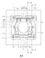
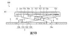
接著,請參照圖1至圖5B,圖3B為未按壓時之外觀示意圖,圖4為俯視示意圖,圖5A為圖4之5-5部位之按壓時之側視剖面示意圖,圖5B為圖4之5-5部位之未按壓時之側視剖面示意圖。本實施例中,連接組件3包括第一連接件31及第二連接件32,第一連接件31及第二連接件32位於底板1與鍵帽2之間,並且,第一連接件31一端31b連接於底板1,第一連接件31另一端31c連接於鍵帽2,第二連接件32一端32b連接於底板1,第二連接件32另一端32c連接於鍵帽2。複數突出結構體4分別設置於第一連接件31之上表面31a及第二連接件32之上表面32a。也就是說,在第一連接件31與第二連接件32其二者上方(對應鍵帽2底面2a)皆設置有複數突出結構體4,但非以此為限。在一些實施例中,複數突出結構體4可分別設置於第一連接件31之上表面31a或第二連接件32之上表面32a。其中,各突出結構體4面向於鍵帽2之底面2a。Next, please refer to FIGS. 1 to 5B. FIG. 3B is a schematic diagram of the appearance when not pressed, FIG. 4 is a schematic top view, FIG. 5A is a schematic cross-sectional side view of positions 5-5 of FIG. 4 when pressed, and FIG. 5B is FIG. 4 Schematic diagram of the side cross-sectional view of positions 5-5 when not pressed. In this embodiment, the connecting
參照圖1、圖2、圖3A、圖3B、圖5B及圖6B,更詳細地說,內框型本體310與外框型本體320相互樞接為X型(稱剪刀型)之連接組件3,但不以此為限。於實際應用中,連接組件3亦可替換為其他具有類似功能(即帶動鍵帽2相對底板1進行升降)之結構,例如V型或A型之連桿結構。更詳細地說,第一連接件31一端31b設有第一下軸部313、第一連接件31另一端31c設有第一上軸部311,而第二連接件32一端32b設有第二下軸部323、第二連接件32另一端32c設有第二上軸部321。第一連接件31之第一下軸部313、第二連接件32之第二下軸部323係組接於設在底板1上的複數勾部113、123。更詳細地說,第一連接件31之第一上軸部311、第二連接件32之第二上軸部321分別組接於設在鍵帽2之底面2a的樞孔211與倒勾221。在此,第一上軸部311與樞孔211為樞接結合,形成鍵帽的固定側,第二上軸部321與倒勾221為鬆配合限位,形成鍵帽的滑動側。藉以使連接組件3可活動連結於底板1與鍵帽2之間。1, 2, 3A, 3B, 5B, and 6B, in more detail, the inner
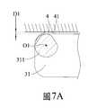
參照圖1、圖2、圖7A及圖7B,更詳細地說,第一連接件31側端形成凹槽,凹槽中形成有橫向軸桿的第一上軸部311,軸桿截面為圓形但兩側形成斜面設計。第二上軸部321為突塊設置在第二連接件32外側面,突塊截面為橫向梯形設計,上下兩對邊不平行(下表面平面、上表面斜面)。1, 2, 7A and 7B, in more detail, a groove is formed at the side end of the first connecting
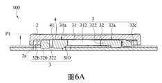
參照圖1至圖7B,圖6A為圖4之6-6部位之按壓時之側視剖面示意圖,圖6B為圖4之6-6部位之未按壓時之側視剖面示意圖,圖7A為一實施態樣之第一上軸部位置處之局部側視剖面示意圖,圖7B一實施態樣之第二上軸部位置處之局部側視剖面示意圖。更詳細地說,按壓鍵帽2至下壓位置P1時,即鍵帽2被完全按壓至最低點,鍵帽2之底面2a的中央處會壓置彈性體(圖未示),鍵帽2之底面2a的外圍接觸於複數突出結構體4,複數突出結構體4頂開於鍵帽2使鍵帽2與連接組件3之間形成有空隙 D1/D2(如圖7A、圖7B所示)。1 to 7B, FIG. 6A is a schematic side sectional view of the position 6-6 of FIG. 4 when pressed, FIG. 6B is a schematic side sectional view of the position 6-6 of FIG. 4 when not pressed, and FIG. 7A is a A schematic partial side cross-sectional view at the position of the first upper shaft of the embodiment, and FIG. 7B is a schematic partial side cross-sectional view at the position of the second upper shaft of the embodiment. In more detail, when the
更詳細地說,按壓鍵帽2至下壓位置P1時,第一連接件31及第二連接件32橫向設置且非平行。並且,第二連接件32上的突出結構體4頂開鍵帽2所形成的空隙D2距離,大於第一連接件31上的突出結構體4頂開鍵帽2所形成的空隙D1距離。第二連接件32上的突出結構體4厚度大於第一連接件31上的突出結構體4厚度,非以此為限。在一些實施態樣中,第二連接件32上的突出結構體4厚度可等於或小於第一連接件31上的突出結構體4厚度。In more detail, when the
換言之,鍵帽2內側面接觸於第一連接件31的上表面31a的凸點(面接觸點)與第二連接件32的上表面32a的凸點(面接觸點)。特別是,按鍵100的各結構在設計上保留有公差,鬆配合的組配關係,組配後按鍵100的各結構之間有些許間隙,一般按壓按鍵100時會產生噪音。在此,透過本發明實施例之設計,鍵帽2受按壓後,會直接接觸設於第一連接件31上表面31a及第二連接件32上表面32a之突出結構體4,藉此消除細微噪音。In other words, the inner surface of the
也就是說,鍵帽2下壓至下死點(擠壓彈性體(圖未示)至一壓縮固定位置),第一連接件31與第二連接件32上的複數突出結構體4頂住鍵帽2底面2a。其中,第一連接件31與第二連接件32不會產生平行。故鍵帽2底面2a無法碰觸第一連接件31的上表面31a(面接觸面)與第二連接件32的上表面32a(面接觸面),因此,不會產生撞擊音。That is, the
另外,可藉由複數突出結構體4的厚度變化或設置位置變化、或藉由連接組件3與鍵帽2、底板1的樞接位置變化等,供按壓鍵帽2至下壓位置P1時,第一連接件31及第二連接件32橫向設置且形成非平行狀態。In addition, when the
參照圖1、圖2、圖7A及圖7B,本實施例中,突出結構體4設置於第一連接件31另一端31c,突出結構體4之中心點O1與第一上軸部311之中心點O1為相同中心點設置,但非以此為限。參照圖8A及圖8B,圖8A為另一實施態樣之第一上軸部311位置處之局部側視剖面示意圖,圖8B為另一實施態樣之第二上軸部321位置處之局部側視剖面示意圖。在一些實例態樣中,突出結構體4之中心點O2與第一上軸部311之中心點O1可為不同中心點設置。本實施例中,突出結構體4之中心點O1與第一上軸部311之中心點O1為相同中心點設置,其中,鍵帽2樞接於第一上軸部311。因相同中心點設置的設計,鍵帽2由上頂位置P2至下壓位置P1、或由下壓位置P1至上頂位置P2時,鍵帽2之底面2a順著複數突出結構體4之弧形結構41表面移動,鍵帽2之底面2a會持續接觸於複數突出結構體4之弧形結構41表面。更詳細地說,突出結構體4設置於第二連接件32另一端32c,突出結構體4之中心點O1與第二上軸部321之中心點O1為相同中心點設置,但非以此為限。參照圖8A及圖8B,在一些實例態樣中,突出結構體4之中心點O2與第二上軸部321之中心點O1為不同中心點設置。1, 2, 7A and 7B, in this embodiment, the protruding
參照圖1、圖2、圖6A及圖6B、圖7A及圖7B,本實施例中,鍵帽2回復至上頂位置P2時,鍵帽2之底面2a接觸於複數突出結構體4,使鍵帽2與複數突出結構體4之間的連接處無間隙。其中,若有間隙存在,按壓鍵帽2時會產生噪音。換言之,按鍵100結構上頂至上死點時,鍵帽2與複數突出結構體4之間的連接處緊密接觸,突出結構體4透過接觸鍵帽2產生微小的干涉配合,避免產生撞擊音,消除噪音。1, 2, 6A and 6B, 7A and 7B, in this embodiment, when the
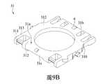
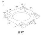
參照圖9A、圖9B、圖9C及圖9D,圖9A為第一連接件上的突出結構體實施態樣一之外觀示意圖,圖9B為第一連接件上的突出結構體實施態樣二之外觀示意圖,圖9C為第一連接件上的突出結構體實施態樣三之外觀示意圖,圖9D為第一連接件上的突出結構體實施態樣四之外觀示意圖。在一些實施態樣中,可在第一連接件31之側臂312的上表面31a任何位置設置突出結構體4,意即,複數突出結構體4設置於內框型本體310之複數側臂312的上表面31a的任何位置。其中,在側臂312上皆可設置有一個或多個突出結構體4。9A, 9B, 9C and 9D, FIG. 9A is a schematic diagram of the appearance of the first embodiment of the protruding structure on the first connector, and FIG. 9B is the second embodiment of the protruding structure on the first connector Fig. 9C is a schematic view of the appearance of the third embodiment of the protruding structure on the first connector, and Fig. 9D is a schematic view of the appearance of the fourth embodiment of the protruding structure on the first connector. In some embodiments, the protruding
參照圖9A,複數突出結構體4設置於第一連接件31左右兩側側臂312的中央位置,按壓鍵帽2至接近下壓位置P1時,鍵帽2之底面2a接觸於複數突出結構體4,各側臂312上複數突出結構體4彈性抵持鍵帽2,頂開於鍵帽2使鍵帽2與連接組件3之間形成有空隙D1/D2(如圖7A、圖7B所示)。9A, the plurality of protruding
參照圖9B,複數突出結構體4設置於第一連接件31前後兩側側臂312(一長一短側臂)的中央位置,位於長側臂312上的突出結構體4之中心點O1與第一上軸部311之中心點O1為相同中心點設置,鍵帽2由上頂位置P2至下壓位置P1、或由下壓位置P1至上頂位置P2時,鍵帽2之底面2a順著複數突出結構體4之弧形結構41表面移動,鍵帽2之底面2a持續接觸於複數突出結構體4之弧形結構41表面。另外,按壓鍵帽2至下壓位置P1的定點位置時,鍵帽2之底面2a接觸位於短側臂312上的突出結構體4。各側臂312結構特性,供各側臂312中央位置的複數突出結構體4彈性抵持鍵帽2,頂開於鍵帽2使鍵帽2與連接組件3之間形成有空隙D1/D2(如圖7A、圖7B所示)。9B, the plurality of protruding
參照圖9C,複數突出結構體4設置於第一連接件31上並相鄰於兩側第一下軸部313的內側位置。其中,第一下軸部313位於第一連接件31角落,對應上方之鍵帽2的相鄰邊角的位置。按壓測試鍵帽2的邊角時,並且,按壓鍵帽2至下壓位置P1的定點位置時,鍵帽2之底面2a的外圍接觸於複數突出結構體4,複數突出結構體4頂開於鍵帽2使鍵帽2與連接組件3之間形成有空隙D1/D2(如圖7A、圖7B所示)。Referring to FIG. 9C, the plurality of protruding
參照圖9D,複數突出結構體4設置於第一連接件31上並相鄰於兩側第一上軸部311的外側位置。其中,第一上軸部311位於第一連接件31角落,對應上方之鍵帽2的相鄰邊角的位置。按壓測試鍵帽2的邊角時,並且,按壓鍵帽2至下壓位置P1時,鍵帽2之底面2a的外圍接觸於複數突出結構體4,複數突出結構體4頂開於鍵帽2使鍵帽2與連接組件3之間形成有空隙D1/D2(如圖7A、圖7B所示)。另外,鍵帽2由上頂位置P2至下壓位置P1、或由下壓位置P1至上頂位置P2時,鍵帽2之底面2a順著複數突出結構體4之弧形結構41表面移動,鍵帽2之底面2a持續接觸於複數突出結構體4之弧形結構41表面,頂開於鍵帽2使鍵帽2與連接組件3之間形成有空隙D1/D2(如圖7A、圖7B所示)。Referring to FIG. 9D, the plurality of protruding
參照圖10A、圖10B、圖10C及圖10D,圖10A為第二連接件上的突出結構體實施態樣一之外觀示意圖,圖10B為第二連接件上的突出結構體實施態樣二之外觀示意圖,圖10C為第二連接件上的突出結構體實施態樣三之外觀示意圖,圖10D為第二連接件上的突出結構體實施態樣四之外觀示意圖。在一些實施態樣中,可在第二連接件32之側臂322的上表面32a任何位置設置突出結構體4,意即,複數突出結構體4可設置於外框型本體320之複數側臂322的上表面32a。其中,在側臂322上皆可設置有一個或多個突出結構體4。10A, FIG. 10B, FIG. 10C and FIG. 10D, FIG. 10A is a schematic diagram of the appearance of the first embodiment of the protruding structure on the second connector, and FIG. 10B is the second embodiment of the protruding structure on the second connector Fig. 10C is a schematic view of the appearance of the third embodiment of the protruding structure on the second connector, and Fig. 10D is a schematic view of the appearance of the fourth embodiment of the protruding structure on the second connector. In some embodiments, the protruding
參照圖10A,複數突出結構體4設置於第二連接件32左右兩側側臂322的相鄰中央位置,按壓鍵帽2至接近下壓位置P1時,鍵帽2之底面2a接觸於複數突出結構體4。各側臂322結構特性,供各側臂322略中央位置的複數突出結構體4彈性抵持鍵帽2,頂開於鍵帽2使鍵帽2與連接組件3之間形成有空隙D1/D2(如圖7A、圖7B所示)。10A, the plurality of protruding
參照圖10B,複數突出結構體4設置於第二連接件32前後兩側側臂322(一長一短側臂)的中央位置,位於短側臂322上的突出結構體4之中心點O1與第二上軸部321之中心點O1為相同中心點設置,鍵帽2由上頂位置P2至下壓位置P1、或由下壓位置P1至上頂位置P2時,鍵帽2之底面2a順著複數突出結構體4之弧形結構41表面移動,鍵帽2之底面2a持續接觸於複數突出結構體4之弧形結構41表面。另外,按壓鍵帽2至下壓位置P1的定點位置時,鍵帽2之底面2a接觸位於長側臂322上的突出結構體4。各側臂322上複數突出結構體4彈性抵持鍵帽2,頂開於鍵帽2使鍵帽2與連接組件3之間形成有空隙D1/D2(如圖7A、圖7B所示)。10B, the plurality of protruding
參照圖10C,複數突出結構體4設置於第二連接件32上並相鄰於兩側第二下軸部323的內側位置。其中,第二下軸部323位於第二連接件32角落,對應上方之鍵帽2的相鄰邊角的位置。按壓測試鍵帽2的邊角時,並且,按壓鍵帽2至下壓位置P1的定點位置時,鍵帽2之底面2a的外圍接觸於複數突出結構體4,複數突出結構體4頂開於鍵帽2使鍵帽2與連接組件3之間形成有空隙D1/D2(如圖7A、圖7B所示)。Referring to FIG. 10C, the plurality of protruding
參照圖10D,複數突出結構體4設置於第二連接件32上並相鄰於兩側第二上軸部321的外側位置。其中,第二上軸部321位於第二連接件32角落,對應上方之鍵帽2的相鄰邊角的位置。按壓測試鍵帽2的邊角時,並且,按壓鍵帽2至下壓位置P1時,鍵帽2之底面2a的外圍接觸於複數突出結構體4,複數突出結構體4頂開於鍵帽2使鍵帽2與連接組件3之間形成有空隙D1/D2(如圖7A、圖7B所示)。另外,鍵帽2由上頂位置P2至下壓位置P1、或由下壓位置P1至上頂位置P2時,鍵帽2之底面2a順著複數突出結構體4之弧形結構41表面移動,鍵帽2之底面2a持續接觸於複數突出結構體4之弧形結構41表面,頂開於鍵帽2使鍵帽2與連接組件3之間形成有空隙D1/D2(如圖7A、圖7B所示)。Referring to FIG. 10D, the plurality of protruding
參照9A至圖10D,在一些實施態樣中,複數突出結構體4可同時設置於外框型本體320之複數側臂322的上表面32a、以及複數突出結構體4設置於內框型本體310之複數側臂312的上表面31a。Referring to 9A to 10D, in some embodiments, the plurality of protruding
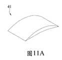
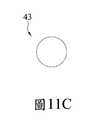
參照圖11A至圖11C,圖11A為突出結構體4實施態樣一之外觀示意圖,圖11B為突出結構體4實施態樣二之外觀示意圖,圖11C為突出結構體4實施態樣三之外觀示意圖。本實施例中,各突出結構體4為弧形結構41為例子作說明,但非以此為限。在一些實施態樣中,各突出結構體4可為圓錐結構42或球結構43(露出部分球結構43於連接組件3的上表面31a或32a)。其中,弧形結構41、圓錐結構42或球結構43的突出結構體4為以點接觸於鍵帽2之底面2a,非以此為限。鍵帽2之底面2a接觸第一連接件31的上表面31a的弧形結構41、圓錐結構42或球結構43(面接觸點)與第二連接件32的上表面32a的弧形結構41、圓錐結構42或球結構43(面接觸點),得以消除噪音。11A to 11C, FIG. 11A is a schematic diagram of the appearance of the protruding
參照圖11D,圖11D為突出結構體4實施態樣四之外觀示意圖,在一些實施態樣中,各突出結構體4可為圓柱結構44,圓柱結構44的突出結構體4非以點接觸於鍵帽2之底面2a,而是以面接觸於鍵帽2之底面2a,非以此為限。鍵帽2之底面2a接觸第一連接件31的上表面31a的圓柱結構44(面接觸面)與第二連接件32的上表面32a的圓柱結構44(面接觸面),得以消除噪音。11D, FIG. 11D is a schematic diagram of the appearance of the fourth embodiment of the protruding
參照圖11E,圖11E為突出結構體4實施態樣五之外觀示意圖,在一些實施態樣中,各突出結構體4可為長條肋結構45,長條肋結構45的突出結構體4非以面接觸於鍵帽2之底面2a,而是以線接觸於鍵帽2之底面2a。鍵帽2之底面2a接觸第一連接件31的上表面31a的長條肋結構45(面接觸線)與第二連接件32的上表面32a的長條肋結構45(面接觸線),得以消除噪音。11E, FIG. 11E is a schematic diagram of the appearance of the fifth embodiment of the protruding
本實施例中,各突出結構體4與連接組件3為一體成型製成,但非以此為限。在一些實例態樣中,可在連接組件3上加工塗上突出結構體4、或者是透過加工組裝方式將突出結構體4結合在連接組件3上。In this embodiment, each protruding
本創作一實施例在按壓鍵帽至下壓位置時,第一連接件與第二連接件上的複數突出結構體頂住鍵帽之底面,複數突出結構體頂開於鍵帽使鍵帽與連接組件之間形成有空隙,鍵帽之底面無法碰觸第一連接件的上表面與第二連接件的上表面,避免面接觸面所產生的撞擊音,得以消除噪音。另外,鍵帽至上頂位置時,鍵帽之底面接觸於複數突出結構體,使鍵帽與複數突出結構體之間的連接處無間隙,得以消除噪音。In an embodiment of this invention, when the key cap is pressed to the down position, the plurality of protruding structures on the first connecting piece and the second connecting piece bear against the bottom surface of the key cap, and the plurality of protruding structures are opened on the key cap to make the key cap and A gap is formed between the connecting components, and the bottom surface of the key cap cannot touch the upper surface of the first connecting piece and the upper surface of the second connecting piece, avoiding the impact sound generated by the surface contacting surface and eliminating noise. In addition, when the keycap reaches the top position, the bottom surface of the keycap is in contact with the plurality of protruding structures, so that there is no gap between the key cap and the plurality of protruding structures, and noise can be eliminated.
透過之詳細說明,即可充分顯示本創作之目的及功效上均具有實施之進步性,極具產業之利用性價值,完全符合專利要件,爰依法提出申請。唯以上僅為本創作之較佳實施例而已,當不能用以限定本創作所實施之範圍。即凡依本創作專利範圍所作之均等變化與修飾,皆應屬於本創作專利涵蓋之範圍內,謹請 貴審查委員明鑑,並祈惠准,是所至禱。Through the detailed description, it can fully show that the purpose and effect of this creation are progressive in implementation, have great industrial utility value, and fully comply with the patent requirements, and the application is filed in accordance with the law. However, the above are only the preferred embodiments of this creation, and should not be used to limit the scope of implementation of this creation. That is to say, all the equal changes and modifications made in accordance with the scope of this creation patent should fall within the scope of this creation patent. I would like to ask your review committee to expressly review and pray for your approval.
100:按鍵100: Button
1:底板1: bottom plate
113:勾部113: Hook
123:勾部123: Hook
2:鍵帽2: keycap
2a:底面2a: bottom surface
211:樞孔211: Pivot
221:倒勾221: Undercut
3:連接組件3: Connect the components
31:第一連接件31: The first connecting piece
31a:上表面31a: upper surface
31b:一端31b: one end
310:內框型本體310: Inner frame type body
311:第一上軸部311: First upper shaft
312:側臂312: side arm
313:第一下軸部313: first lower shaft
32:第二連接件32: The second connecting piece
32a:上表面32a: upper surface
32b:一端32b: one end
32c:另一端32c: the other end
320:外框型本體320: Frame type body
321:第二上軸部321: second upper shaft
322:側臂322: side arm
323:第二下軸部323: second lower shaft
4:突出結構體4: Highlight the structure
41:弧形結構41: Arc structure
42:圓錐結構42: Cone structure
43:球結構43: Ball structure
44:圓柱結構44: Cylindrical structure
45:長條肋結構45: Long rib structure
D1/D2:空隙D1/D2: gap
P1:下壓位置P1: down position
P2:上頂位置P2: Top position
O1/O2:中心點O1/O2: center point
[圖1]本創作一實施例之正面分解示意圖。 [圖2]本創作一實施例之背面分解示意圖。 [圖3A]本創作一實施例之按壓時之外觀示意圖。 [圖3B]本創作一實施例之未按壓時之外觀示意圖。 [圖4]本創作一實施例之俯視示意圖。 [圖5A]為圖4之5-5部位之按壓時之側視剖面示意圖。 [圖5B]為圖4之5-5部位之未按壓時之側視剖面示意圖。 [圖6A]為圖4之6-6部位之按壓時之側視剖面示意圖。 [圖6B]為圖4之6-6部位之未按壓時之側視剖面示意圖。 [圖7A]本創作一實施態樣之第一上軸部位置處之局部側視剖面示意圖。 [圖7B]本創作一實施態樣之第二上軸部位置處之局部側視剖面示意圖。 [圖8A]本創作另一實施態樣之第一上軸部位置處之局部側視剖面示意圖。 [圖8B]本創作另一實施態樣之第二上軸部位置處之局部側視剖面示意圖。 [圖9A]本創作之第一連接件上的突出結構體實施態樣一之外觀示意圖。 [圖9B]本創作之第一連接件上的突出結構體實施態樣二之外觀示意圖。 [圖9C]本創作之第一連接件上的突出結構體實施態樣三之外觀示意圖。 [圖9D]本創作之第一連接件上的突出結構體實施態樣四之外觀示意圖。 [圖10A]本創作之第二連接件上的突出結構體實施態樣一之外觀示意圖。 [圖10B]本創作之第二連接件上的突出結構體實施態樣二之外觀示意圖。 [圖10C]本創作之第二連接件上的突出結構體實施態樣三之外觀示意圖。 [圖10D]本創作之第二連接件上的突出結構體實施態樣四之外觀示意圖。 [圖11A]本創作之突出結構體實施態樣一之外觀示意圖。 [圖11B]本創作之突出結構體實施態樣二之外觀示意圖。 [圖11C]本創作之突出結構體實施態樣三之外觀示意圖。 [圖11D]本創作之突出結構體實施態樣四之外觀示意圖。 [圖11E]本創作之突出結構體實施態樣五之外觀示意圖。[Figure 1] A front exploded schematic diagram of an embodiment of this creation. [Figure 2] An exploded schematic view of the back of an embodiment of this creation. [Figure 3A] A schematic diagram of the appearance of an embodiment of the present creation when pressed. [Figure 3B] A schematic diagram of the appearance of an embodiment of the present creation when it is not pressed. [Figure 4] A schematic top view of an embodiment of this creation. [Fig. 5A] is a schematic side sectional view of the position 5-5 of Fig. 4 when pressed. [Fig. 5B] is a schematic side view of the section 5-5 of Fig. 4 when it is not pressed. [Fig. 6A] is a schematic side sectional view of the position 6-6 of Fig. 4 when pressed. [Fig. 6B] is a schematic side view of the section 6-6 of Fig. 4 when it is not pressed. [Fig. 7A] A schematic partial side sectional view at the position of the first upper shaft part of an embodiment of the present creation. [Fig. 7B] A schematic partial side sectional view at the position of the second upper shaft of an embodiment of this creation. [Fig. 8A] A schematic partial side sectional view at the position of the first upper shaft of another embodiment of the present creation. [Figure 8B] A schematic partial side sectional view of another embodiment of the present creation at the position of the second upper shaft portion. [Figure 9A] A schematic diagram of the appearance of the first embodiment of the protruding structure on the first connector of this creation. [Figure 9B] A schematic diagram of the appearance of the second embodiment of the protruding structure on the first connecting piece of this creation. [Figure 9C] A schematic diagram of the appearance of the third embodiment of the protruding structure on the first connector of this creation. [Figure 9D] A schematic diagram of the appearance of the fourth embodiment of the protruding structure on the first connecting piece of this creation. [Figure 10A] A schematic diagram of the appearance of the first embodiment of the protruding structure on the second connecting piece of this creation. [Figure 10B] A schematic diagram of the appearance of the second embodiment of the protruding structure on the second connecting piece of this creation. [Figure 10C] A schematic diagram of the appearance of the third embodiment of the protruding structure on the second connector of this creation. [Figure 10D] A schematic diagram of the appearance of the fourth embodiment of the protruding structure on the second connector of this creation. [Figure 11A] A schematic diagram of the appearance of the first implementation aspect of the prominent structure of this creation. [Figure 11B] A schematic diagram of the appearance of the second implementation aspect of the prominent structure of this creation. [Figure 11C] A schematic diagram of the appearance of the third implementation aspect of the prominent structure of this creation. [Figure 11D] A schematic diagram of the appearance of the fourth implementation aspect of the prominent structure of this creation. [Figure 11E] A schematic diagram of the appearance of the fifth implementation pattern of the prominent structure of this creation.
100:按鍵100: Button
1:底板1: bottom plate
113:勾部113: Hook
123:勾部123: Hook
2:鍵帽2: keycap
3:連接組件3: Connect the components
31:第一連接件31: The first connecting piece
31a:上表面31a: upper surface
31b:一端31b: one end
31c:另一端31c: the other end
310:內框型本體310: Inner frame type body
311:第一上軸部311: First upper shaft
312:側臂312: side arm
313:第一下軸部313: first lower shaft
32:第二連接件32: The second connecting piece
32a:上表面32a: upper surface
32b:一端32b: one end
32c:另一端32c: the other end
320:外框型本體320: Frame type body
321:第二上軸部321: second upper shaft
322:側臂322: side arm
323:第二下軸部323: second lower shaft
4:突出結構體4: Highlight the structure
41:弧形結構41: Arc structure
Claims (10)
Translated fromChinesePriority Applications (2)
| Application Number | Priority Date | Filing Date | Title |
|---|---|---|---|
| TW109124351ATWI724946B (en) | 2020-07-17 | 2020-07-17 | Key |
| US17/209,885US11328880B2 (en) | 2020-07-17 | 2021-03-23 | Key |
Applications Claiming Priority (1)
| Application Number | Priority Date | Filing Date | Title |
|---|---|---|---|
| TW109124351ATWI724946B (en) | 2020-07-17 | 2020-07-17 | Key |
Publications (2)
| Publication Number | Publication Date |
|---|---|
| TWI724946Btrue TWI724946B (en) | 2021-04-11 |
| TW202205324A TW202205324A (en) | 2022-02-01 |
Family
ID=76604901
Family Applications (1)
| Application Number | Title | Priority Date | Filing Date |
|---|---|---|---|
| TW109124351ATWI724946B (en) | 2020-07-17 | 2020-07-17 | Key |
Country Status (2)
| Country | Link |
|---|---|
| US (1) | US11328880B2 (en) |
| TW (1) | TWI724946B (en) |
Family Cites Families (3)
| Publication number | Priority date | Publication date | Assignee | Title |
|---|---|---|---|---|
| JP3652254B2 (en)* | 2001-01-23 | 2005-05-25 | 韓国エスエムケイ株式会社 | Key switch |
| TWI592969B (en)* | 2016-09-14 | 2017-07-21 | 致伸科技股份有限公司 | Key structure |
| CN110265252A (en) | 2019-05-31 | 2019-09-20 | 苏州达方电子有限公司 | key structure |
- 2020
- 2020-07-17TWTW109124351Apatent/TWI724946B/enactive
- 2021
- 2021-03-23USUS17/209,885patent/US11328880B2/enactiveActive
Also Published As
| Publication number | Publication date |
|---|---|
| US11328880B2 (en) | 2022-05-10 |
| US20220020543A1 (en) | 2022-01-20 |
| TW202205324A (en) | 2022-02-01 |
Similar Documents
| Publication | Publication Date | Title |
|---|---|---|
| TWI564922B (en) | Key connecting module | |
| CN106683930B (en) | keyboard structure | |
| US20130140164A1 (en) | Thin film switch and press key/keyboard using the same | |
| TW202009959A (en) | keyboard | |
| TW201836216A (en) | Keyboard structure | |
| TW202205326A (en) | Low height key structure | |
| TW202217885A (en) | Key structure | |
| TWI564923B (en) | Key structure | |
| TW201839788A (en) | Key structure | |
| TWI724946B (en) | Key | |
| TWI696203B (en) | Keyboard structure | |
| TW202028932A (en) | Mouse device | |
| TW202009964A (en) | Silent keyboard and key structure thereof | |
| CN108666163A (en) | Key structure | |
| TWI632574B (en) | Keyswitch | |
| CN110828216B (en) | Keyboard with mute function and key structure thereof | |
| CN114068217A (en) | Push-button | |
| CN107170612A (en) | Keyboard and its button | |
| CN111292991B (en) | Reinforced press key | |
| TW202338879A (en) | Keyboard device and a key structure | |
| TWI827156B (en) | Keyboard device | |
| TWM523955U (en) | Key button structure | |
| CN201984995U (en) | Keycap assembly, key and keyboard | |
| CN106548892A (en) | Magnetic key for keyboard | |
| CN112783340A (en) | Mouse device |