TWI723172B - Electrostatic work clamp table, laser processing device and processing method of processed object - Google Patents
Electrostatic work clamp table, laser processing device and processing method of processed objectDownload PDFInfo
- Publication number
- TWI723172B TWI723172BTW106118506ATW106118506ATWI723172BTW I723172 BTWI723172 BTW I723172BTW 106118506 ATW106118506 ATW 106118506ATW 106118506 ATW106118506 ATW 106118506ATW I723172 BTWI723172 BTW I723172B
- Authority
- TW
- Taiwan
- Prior art keywords
- workpiece
- laser light
- holding
- electrostatic
- electrostatic work
- Prior art date
Links
- 238000012545processingMethods0.000titleclaimsabstractdescription53
- 238000003672processing methodMethods0.000titleclaimsdescription16
- 238000001179sorption measurementMethods0.000claimsabstractdescription18
- 230000001678irradiating effectEffects0.000claimsabstractdescription6
- 230000000149penetrating effectEffects0.000claimsdescription19
- 238000000034methodMethods0.000claimsdescription17
- 239000011347resinSubstances0.000claimsdescription12
- 229920005989resinPolymers0.000claimsdescription12
- 238000002407reformingMethods0.000claimsdescription3
- 229920002799BoPETPolymers0.000abstractdescription11
- 229910052751metalInorganic materials0.000abstractdescription10
- 239000002184metalSubstances0.000abstractdescription10
- 230000007246mechanismEffects0.000description21
- 239000000853adhesiveSubstances0.000description15
- 230000001070adhesive effectEffects0.000description15
- 235000012431wafersNutrition0.000description12
- 239000002390adhesive tapeSubstances0.000description9
- 238000003384imaging methodMethods0.000description7
- AMGQUBHHOARCQH-UHFFFAOYSA-Nindium;oxotinChemical compound[In].[Sn]=OAMGQUBHHOARCQH-UHFFFAOYSA-N0.000description4
- 239000004973liquid crystal related substanceSubstances0.000description3
- 230000003287optical effectEffects0.000description3
- 230000010355oscillationEffects0.000description3
- 239000000470constituentSubstances0.000description2
- 238000001514detection methodMethods0.000description2
- 230000000694effectsEffects0.000description2
- 229920000139polyethylene terephthalatePolymers0.000description2
- 239000005020polyethylene terephthalateSubstances0.000description2
- 230000008569processEffects0.000description2
- 239000004065semiconductorSubstances0.000description2
- GYHNNYVSQQEPJS-UHFFFAOYSA-NGalliumChemical compound[Ga]GYHNNYVSQQEPJS-UHFFFAOYSA-N0.000description1
- 230000004308accommodationEffects0.000description1
- 238000013459approachMethods0.000description1
- 230000015556catabolic processEffects0.000description1
- 230000008859changeEffects0.000description1
- 238000004590computer programMethods0.000description1
- 238000013461designMethods0.000description1
- 230000005674electromagnetic inductionEffects0.000description1
- 229910052733galliumInorganic materials0.000description1
- 239000011521glassSubstances0.000description1
- 238000009413insulationMethods0.000description1
- 230000010354integrationEffects0.000description1
- 238000010030laminatingMethods0.000description1
- 239000000463materialSubstances0.000description1
- 230000005055memory storageEffects0.000description1
- 238000012986modificationMethods0.000description1
- 230000004048modificationEffects0.000description1
- 230000002093peripheral effectEffects0.000description1
- 230000035699permeabilityEffects0.000description1
- 230000000704physical effectEffects0.000description1
- 230000005855radiationEffects0.000description1
- 229910052594sapphireInorganic materials0.000description1
- 239000010980sapphireSubstances0.000description1
- 229910052710siliconInorganic materials0.000description1
- 239000010703siliconSubstances0.000description1
- 238000012360testing methodMethods0.000description1
- XLYOFNOQVPJJNP-UHFFFAOYSA-NwaterSubstancesOXLYOFNOQVPJJNP-UHFFFAOYSA-N0.000description1
Images


Classifications
- H—ELECTRICITY
- H01—ELECTRIC ELEMENTS
- H01L—SEMICONDUCTOR DEVICES NOT COVERED BY CLASS H10
- H01L21/00—Processes or apparatus adapted for the manufacture or treatment of semiconductor or solid state devices or of parts thereof
- H01L21/67—Apparatus specially adapted for handling semiconductor or electric solid state devices during manufacture or treatment thereof; Apparatus specially adapted for handling wafers during manufacture or treatment of semiconductor or electric solid state devices or components ; Apparatus not specifically provided for elsewhere
- H01L21/683—Apparatus specially adapted for handling semiconductor or electric solid state devices during manufacture or treatment thereof; Apparatus specially adapted for handling wafers during manufacture or treatment of semiconductor or electric solid state devices or components ; Apparatus not specifically provided for elsewhere for supporting or gripping
- H01L21/6831—Apparatus specially adapted for handling semiconductor or electric solid state devices during manufacture or treatment thereof; Apparatus specially adapted for handling wafers during manufacture or treatment of semiconductor or electric solid state devices or components ; Apparatus not specifically provided for elsewhere for supporting or gripping using electrostatic chucks
- H01L21/6833—Details of electrostatic chucks
- B—PERFORMING OPERATIONS; TRANSPORTING
- B23—MACHINE TOOLS; METAL-WORKING NOT OTHERWISE PROVIDED FOR
- B23K—SOLDERING OR UNSOLDERING; WELDING; CLADDING OR PLATING BY SOLDERING OR WELDING; CUTTING BY APPLYING HEAT LOCALLY, e.g. FLAME CUTTING; WORKING BY LASER BEAM
- B23K26/00—Working by laser beam, e.g. welding, cutting or boring
- B23K26/352—Working by laser beam, e.g. welding, cutting or boring for surface treatment
- B23K26/359—Working by laser beam, e.g. welding, cutting or boring for surface treatment by providing a line or line pattern, e.g. a dotted break initiation line
- B—PERFORMING OPERATIONS; TRANSPORTING
- B23—MACHINE TOOLS; METAL-WORKING NOT OTHERWISE PROVIDED FOR
- B23K—SOLDERING OR UNSOLDERING; WELDING; CLADDING OR PLATING BY SOLDERING OR WELDING; CUTTING BY APPLYING HEAT LOCALLY, e.g. FLAME CUTTING; WORKING BY LASER BEAM
- B23K26/00—Working by laser beam, e.g. welding, cutting or boring
- B23K26/36—Removing material
- B23K26/38—Removing material by boring or cutting
- B—PERFORMING OPERATIONS; TRANSPORTING
- B23—MACHINE TOOLS; METAL-WORKING NOT OTHERWISE PROVIDED FOR
- B23K—SOLDERING OR UNSOLDERING; WELDING; CLADDING OR PLATING BY SOLDERING OR WELDING; CUTTING BY APPLYING HEAT LOCALLY, e.g. FLAME CUTTING; WORKING BY LASER BEAM
- B23K26/00—Working by laser beam, e.g. welding, cutting or boring
- B23K26/50—Working by transmitting the laser beam through or within the workpiece
- B23K26/53—Working by transmitting the laser beam through or within the workpiece for modifying or reforming the material inside the workpiece, e.g. for producing break initiation cracks
- B—PERFORMING OPERATIONS; TRANSPORTING
- B23—MACHINE TOOLS; METAL-WORKING NOT OTHERWISE PROVIDED FOR
- B23K—SOLDERING OR UNSOLDERING; WELDING; CLADDING OR PLATING BY SOLDERING OR WELDING; CUTTING BY APPLYING HEAT LOCALLY, e.g. FLAME CUTTING; WORKING BY LASER BEAM
- B23K37/00—Auxiliary devices or processes, not specially adapted for a procedure covered by only one of the other main groups of this subclass
- B23K37/04—Auxiliary devices or processes, not specially adapted for a procedure covered by only one of the other main groups of this subclass for holding or positioning work
- H—ELECTRICITY
- H01—ELECTRIC ELEMENTS
- H01L—SEMICONDUCTOR DEVICES NOT COVERED BY CLASS H10
- H01L21/00—Processes or apparatus adapted for the manufacture or treatment of semiconductor or solid state devices or of parts thereof
- H01L21/02—Manufacture or treatment of semiconductor devices or of parts thereof
- H01L21/04—Manufacture or treatment of semiconductor devices or of parts thereof the devices having potential barriers, e.g. a PN junction, depletion layer or carrier concentration layer
- H01L21/18—Manufacture or treatment of semiconductor devices or of parts thereof the devices having potential barriers, e.g. a PN junction, depletion layer or carrier concentration layer the devices having semiconductor bodies comprising elements of Group IV of the Periodic Table or AIIIBV compounds with or without impurities, e.g. doping materials
- H01L21/26—Bombardment with radiation
- H01L21/263—Bombardment with radiation with high-energy radiation
- H01L21/268—Bombardment with radiation with high-energy radiation using electromagnetic radiation, e.g. laser radiation
- H—ELECTRICITY
- H01—ELECTRIC ELEMENTS
- H01L—SEMICONDUCTOR DEVICES NOT COVERED BY CLASS H10
- H01L21/00—Processes or apparatus adapted for the manufacture or treatment of semiconductor or solid state devices or of parts thereof
- H01L21/67—Apparatus specially adapted for handling semiconductor or electric solid state devices during manufacture or treatment thereof; Apparatus specially adapted for handling wafers during manufacture or treatment of semiconductor or electric solid state devices or components ; Apparatus not specifically provided for elsewhere
- H01L21/67005—Apparatus not specifically provided for elsewhere
- H01L21/67011—Apparatus for manufacture or treatment
- H01L21/67092—Apparatus for mechanical treatment
- H—ELECTRICITY
- H01—ELECTRIC ELEMENTS
- H01L—SEMICONDUCTOR DEVICES NOT COVERED BY CLASS H10
- H01L21/00—Processes or apparatus adapted for the manufacture or treatment of semiconductor or solid state devices or of parts thereof
- H01L21/67—Apparatus specially adapted for handling semiconductor or electric solid state devices during manufacture or treatment thereof; Apparatus specially adapted for handling wafers during manufacture or treatment of semiconductor or electric solid state devices or components ; Apparatus not specifically provided for elsewhere
- H01L21/67005—Apparatus not specifically provided for elsewhere
- H01L21/67011—Apparatus for manufacture or treatment
- H01L21/67098—Apparatus for thermal treatment
- H01L21/67115—Apparatus for thermal treatment mainly by radiation
- H—ELECTRICITY
- H01—ELECTRIC ELEMENTS
- H01L—SEMICONDUCTOR DEVICES NOT COVERED BY CLASS H10
- H01L21/00—Processes or apparatus adapted for the manufacture or treatment of semiconductor or solid state devices or of parts thereof
- H01L21/67—Apparatus specially adapted for handling semiconductor or electric solid state devices during manufacture or treatment thereof; Apparatus specially adapted for handling wafers during manufacture or treatment of semiconductor or electric solid state devices or components ; Apparatus not specifically provided for elsewhere
- H01L21/683—Apparatus specially adapted for handling semiconductor or electric solid state devices during manufacture or treatment thereof; Apparatus specially adapted for handling wafers during manufacture or treatment of semiconductor or electric solid state devices or components ; Apparatus not specifically provided for elsewhere for supporting or gripping
- H01L21/6831—Apparatus specially adapted for handling semiconductor or electric solid state devices during manufacture or treatment thereof; Apparatus specially adapted for handling wafers during manufacture or treatment of semiconductor or electric solid state devices or components ; Apparatus not specifically provided for elsewhere for supporting or gripping using electrostatic chucks
- H—ELECTRICITY
- H01—ELECTRIC ELEMENTS
- H01L—SEMICONDUCTOR DEVICES NOT COVERED BY CLASS H10
- H01L21/00—Processes or apparatus adapted for the manufacture or treatment of semiconductor or solid state devices or of parts thereof
- H01L21/70—Manufacture or treatment of devices consisting of a plurality of solid state components formed in or on a common substrate or of parts thereof; Manufacture of integrated circuit devices or of parts thereof
- H01L21/77—Manufacture or treatment of devices consisting of a plurality of solid state components or integrated circuits formed in, or on, a common substrate
- H01L21/78—Manufacture or treatment of devices consisting of a plurality of solid state components or integrated circuits formed in, or on, a common substrate with subsequent division of the substrate into plural individual devices
Landscapes
- Engineering & Computer Science (AREA)
- Physics & Mathematics (AREA)
- Power Engineering (AREA)
- Condensed Matter Physics & Semiconductors (AREA)
- General Physics & Mathematics (AREA)
- Manufacturing & Machinery (AREA)
- Computer Hardware Design (AREA)
- Microelectronics & Electronic Packaging (AREA)
- Optics & Photonics (AREA)
- Mechanical Engineering (AREA)
- Plasma & Fusion (AREA)
- High Energy & Nuclear Physics (AREA)
- Toxicology (AREA)
- Health & Medical Sciences (AREA)
- Electromagnetism (AREA)
- Oil, Petroleum & Natural Gas (AREA)
- General Chemical & Material Sciences (AREA)
- Chemical Kinetics & Catalysis (AREA)
- Chemical & Material Sciences (AREA)
- Laser Beam Processing (AREA)
- Container, Conveyance, Adherence, Positioning, Of Wafer (AREA)
- Dicing (AREA)
Abstract
Translated fromChineseDescription
Translated fromChinese發明領域 本發明是有關於一種靜電工作夾台、雷射加工裝置及被加工物的加工方法。FIELD OF THE INVENTION The present invention relates to an electrostatic work clamp table, a laser processing device, and a processing method of a processed object.
發明背景 將雷射加工裝置使用於形成半導體或LED(發光二極體(Light Emitting Diode))等的光元件的晶圓之分割,並以形成於晶圓内部的改質層為破斷基點來進行分割之加工方法是已知的(專利文獻1)。BACKGROUND OF THE INVENTION Laser processing equipment is used for the division of wafers forming optical elements such as semiconductors or LEDs (Light Emitting Diode), and the modified layer formed inside the wafer is used as the breaking point. The processing method for dividing is known (Patent Document 1).
於專利文獻1等中所示之加工方法,由於相較於以往進行之一邊供給切削水一邊以切削刀破碎晶圓之切割,能夠使切口(kerf)寬度變得非常窄,所以對於已進行挾切割道化之晶圓而言是非常的有用。又,於專利文獻1等中所示之加工方法,由於對被加工物的機械性衝撃非常地少,所以在例如形成有被稱為MEMS(微機電系統(Micro Electro Mechanical Systems))之細微的構造體之晶圓的分割中,能夠在不破壞MEMS的情形下進行分割,因而非常有效。 先前技術文獻 專利文獻In the processing method shown in
專利文獻1:日本專利特許第3408805號公報Patent Document 1: Japanese Patent No. 3408805
發明概要 發明欲解決之課題 然而,即便雷射光線可以穿透晶圓,但是其波長不能穿透構成元件的電路等的金屬層,因此為了能夠從晶圓之無金屬層的背面照射雷射光線,必須進行像是將元件面側以工作夾台的保持面來保持、或採用於分割預定線上不形成TEG圖案(測試元件圖案)的特殊設計、或設定事先將TEG圖案去除之步驟。SUMMARY OF THE INVENTION The problem to be solved by the invention. However, even if the laser light can penetrate the wafer, its wavelength cannot penetrate the metal layer of the circuit constituting the element. Therefore, in order to be able to irradiate the laser light from the backside of the wafer without the metal layer , It is necessary to carry out steps such as holding the component surface side with the holding surface of the work clamp, or adopting a special design that does not form a TEG pattern (test component pattern) on the predetermined dividing line, or setting the step to remove the TEG pattern in advance.
本發明是有鑒於所述問題點而作成的發明,其目的在於提供一種靜電工作夾台、雷射加工裝置及被加工物的加工方法,其可在使形成有金屬層或元件的被加工物之正面側露出而將背面側以工作夾台的保持面保持的狀態下,從保持面側進行雷射加工。 用以解決課題之手段The present invention was made in view of the above-mentioned problems, and its object is to provide an electrostatic work clamp table, a laser processing device, and a processing method of a workpiece, which can be used on a workpiece formed with a metal layer or element With the front side exposed and the back side held by the holding surface of the work chuck, laser processing is performed from the holding surface side. Means to solve the problem
根據本發明的第1方面,可提供一種保持被加工物之靜電工作夾台,其具備: 板狀的基台部,具有第1面、及與該第1面相反側之第2面,且對於對被加工物具有穿透性之預定波長的雷射光線具有穿透性; 靜電吸附用的電極部,對該預定波長的雷射光線具有穿透性,且積層於該基台部的該第1面;及 樹脂層,對該預定波長的雷射光線具有穿透性,且構成用以覆蓋該電極部並且保持被加工物之保持面, 該靜電工作夾台適合於從該基台部的該第2面側照射雷射光線,而在以該保持面所保持之該被加工物的内部形成改質層之時使用。According to the first aspect of the present invention, there can be provided an electrostatic work chuck for holding a workpiece, comprising: a plate-shaped base portion having a first surface and a second surface opposite to the first surface, and It has penetrability for the laser light of a predetermined wavelength that is penetrating to the workpiece; the electrode part for electrostatic adsorption has penetrability to the laser light of the predetermined wavelength, and is laminated on the base part. The first surface; and the resin layer, which is transparent to the laser light of the predetermined wavelength, and constitutes a holding surface for covering the electrode portion and holding the processed object, the electrostatic work chuck is suitable from the base portion The second surface side of the laser beam is irradiated to form a modified layer inside the workpiece held by the holding surface.
較理想的是,前述預定波長是在500nm~1400nm的範圍內。Preferably, the aforementioned predetermined wavelength is in the range of 500 nm to 1400 nm.
較理想的是,被加工物是於正面形成有複數個MEMS元件之晶圓所構成,且將該晶圓的背面側以該靜電工作夾台的該保持面保持。Preferably, the object to be processed is composed of a wafer with a plurality of MEMS elements formed on the front surface, and the back side of the wafer is held by the holding surface of the electrostatic work chuck.
根據本發明的第2方面,可提供一種雷射加工裝置,其具備保持被加工物之靜電工作夾台、及以對保持於該靜電工作夾台上的被加工物具有穿透性之波長的雷射光線在被加工物的内部形成改質層之雷射光線照射單元,該靜電工作夾台包含: 板狀的基台部,具有第1面、及與該第1面相反側之第2面,且對於對被加工物具有穿透性之波長的預定波長的雷射光線具有穿透性; 靜電吸附用的電極部,對該預定波長的雷射光線具有穿透性,且積層於該基台部的該第1面;及 樹脂層,對該預定波長的雷射光線有穿透性,且構成用以覆蓋該電極部並且保持被加工物之保持面, 其為以該工作夾台的該保持面保持被加工物的背面側,並從該基台部的該第2面側照射雷射光線,以在該被加工物的内部形成改質層。According to the second aspect of the present invention, there can be provided a laser processing apparatus including an electrostatic work chuck table for holding a workpiece, and a wavelength penetrating the work to be held on the electrostatic work chuck table. The laser beam forms a laser beam irradiation unit in which a modified layer is formed inside the workpiece. The electrostatic work clamp includes: a plate-shaped base part having a first surface and a second surface opposite to the first surface Surface, and has penetrability to laser light of a predetermined wavelength of a wavelength that is penetrative to the workpiece; the electrode part for electrostatic adsorption has penetrability to the laser light of the predetermined wavelength, and is laminated on the The first surface of the base part; and the resin layer, which is transparent to the laser light of the predetermined wavelength and constitutes a holding surface for covering the electrode part and holding the workpiece, which is the work clamp The holding surface holds the back side of the workpiece, and the second surface side of the base portion is irradiated with laser light to form a modified layer inside the workpiece.
根據本發明的第3方面,可提供一種將背面側保持於靜電工作夾台上之被加工物的加工方法,靜電工作夾台具備: 板狀的基台部,具有第1面、及與該第1面相反側的第2面,且對於對被加工物具有穿透性之預定波長的雷射光線具有穿透性; 靜電吸附用的電極部,對該預定波長的雷射光線具有穿透性,且積層於該基台部的該第1面;及 樹脂層,對該預定波長的雷射光線有穿透性,且構成用以覆蓋該電極部並且保持被加工物之保持面, 該被加工物的加工方法包含: 保持步驟,以該靜電工作夾台的該保持面保持被加工物的背面側;及 改質層形成步驟,從該基台部的該第2面側照射雷射光線,以藉由穿透該靜電工作夾台之雷射光線,於以該保持面所保持之該被加工物的内部形成改質層。 發明效果According to the third aspect of the present invention, it is possible to provide a method for processing a workpiece whose back side is held on an electrostatic work chuck table. The electrostatic work chuck table includes: a plate-shaped base portion having a first surface, and The second surface on the opposite side of the first surface, and has penetrability to the laser light of a predetermined wavelength that is penetrative to the workpiece; the electrode part for electrostatic adsorption can penetrate the laser light of the predetermined wavelength And is laminated on the first surface of the base portion; and a resin layer that is transparent to laser light of a predetermined wavelength and constitutes a holding surface for covering the electrode portion and holding the workpiece, the The processing method of the workpiece includes: a holding step of holding the back side of the workpiece with the holding surface of the electrostatic work chuck; and a reforming layer forming step of irradiating a laser from the second surface side of the base portion The light is used by the laser light penetrating the electrostatic work clamp table to form a modified layer inside the processed object held by the holding surface. Invention effect
本發明的靜電工作夾台可達到下述之效果:可在使形成有金屬層或元件的被加工物的正面側露出而將背面側以保持面保持的狀態下,從保持面側進行雷射加工。The electrostatic work chuck of the present invention can achieve the following effect: the front side of the workpiece on which the metal layer or element is formed is exposed and the back side is held in the holding surface, and the laser can be performed from the holding surface side. Processing.
用以實施發明之形態 針對用於實施本發明之形態(實施形態),參照著圖式詳細地說明。本發明並不因以下實施形態所記載之內容而受到限定。又,在以下所記載之構成要素中,包含所屬技術領域中具有通常知識者可輕易設想得到的或實質上是相同的。此外,以下所記載之構成是可以適當組合的。又,在不脫離本發明之要旨的範圍內,可進行各種構成之省略、置換或變更。Mode for Carrying Out the Invention The mode (embodiment) for carrying out the invention will be described in detail with reference to the drawings. The present invention is not limited by the content described in the following embodiments. In addition, the constituent elements described below include those that can be easily imagined by a person with ordinary knowledge in the relevant technical field or are substantially the same. In addition, the configurations described below can be combined as appropriate. In addition, various configurations can be omitted, replaced, or changed without departing from the scope of the present invention.
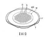
[第1實施形態] 本發明的第1實施形態之靜電工作夾台1是根據圖式來對雷射加工裝置10及被加工物W的加工方法作説明。圖1是顯示第1實施形態之被加工物的加工方法之加工對象的被加工物的立體圖。圖2是顯示將圖1所示之被加工物以環狀框架支撐之狀態的立體圖。[First Embodiment] The electrostatic work chuck 1 according to the first embodiment of the present invention describes the
第1實施形態之被加工物的加工方法是對圖1所示的被加工物W進行加工的方法。圖1所示之被加工物W在本實施形態中,是以矽、藍寶石、鎵等作為母材之圓板狀的半導體晶圓或光元件晶圓。如圖1所示,被加工物W是於正面WS之藉由交差的複數條分割預定線S而區劃出的各區域中形成有元件D的板狀物。作為元件D,可於各區域中形成IC(積體電路(Integrated Circuit))、LSI(大型積體電路(Large Scale Integration))、MEMS(Micro Electro Mechanical Systems:微機電系統)元件。The processing method of the workpiece of the first embodiment is a method of processing the workpiece W shown in FIG. 1. In this embodiment, the workpiece W shown in FIG. 1 is a disc-shaped semiconductor wafer or an optical element wafer with silicon, sapphire, gallium, or the like as a base material. As shown in FIG. 1, the workpiece W is a plate in which the element D is formed in each area of the front surface WS divided by a plurality of intersecting planned dividing lines S. As the element D, IC (Integrated Circuit), LSI (Large Scale Integration), and MEMS (Micro Electro Mechanical Systems) elements can be formed in each area.
如圖2所示,被加工物W是藉由在形成有複數個元件D之正面WS的背側之背面WR貼附黏著膠帶T,並將黏著膠帶T的外緣貼附到環狀框架F上,而被黏著膠帶T支撐於環狀框架F的開口。在第1實施形態中,被加工物W是在被黏著膠帶T支撐於環狀框架F的開口的狀態下,實行被加工物的加工方法,並藉此分割成一個個的元件D。在第1實施形態中,雖然被加工物W於正面形成有作為元件D之MEMS元件,但元件D並不限定為MEMS元件。又,在第1實施形態中,被加工物W是IC或是LSI的情況下,宜為在正面搭載有凸塊或晶片者,並且以正面為凹凸的元件D為較理想。As shown in FIG. 2, the workpiece W is formed by attaching an adhesive tape T to the back side WR of the back side of the front WS on which a plurality of elements D are formed, and attaching the outer edge of the adhesive tape T to the ring frame F , And is supported on the opening of the ring frame F by the adhesive tape T. In the first embodiment, the workpiece W is supported by the adhesive tape T by the opening of the ring frame F, and the processing method of the workpiece is carried out, thereby dividing the workpiece into individual components D. In the first embodiment, although the MEMS element as the element D is formed on the front surface of the workpiece W, the element D is not limited to the MEMS element. Furthermore, in the first embodiment, when the workpiece W is an IC or an LSI, it is preferable to mount bumps or wafers on the front surface, and it is more preferable to use an element D having unevenness on the front surface.
根據圖式來說明第1實施形態之雷射加工裝置10的構成。圖3是顯示第1實施形態的雷射加工裝置之構成例的立體圖。圖4是沿圖3的IV-IV線之截面圖。圖5是顯示第1實施形態之靜電工作夾台之構成例的平面圖。圖6是沿圖5中的VI-VI線之截面圖。圖7是沿圖5中的VII-VII線之截面圖。The structure of the
雷射加工裝置10是將對被加工物W具有穿透性之波長的雷射光線L(圖9所示),從被加工物W的背面WR側沿著分割預定線S照射,而在被加工物W的内部以雷射光線L形成作為破斷起點的改質層K(圖9所示)之裝置。再者,所謂的改質層K是指密度、折射率、機械強度或其他的物理特性變得與周圍之該特性不同之狀態的區域,且可以例示的有熔融處理區域,裂隙(crack)區域、絕緣破壞區域、折射率變化區域、及混合了這些區域的區域等。The
如圖3所示,雷射加工裝置10具備有:將被加工物W以保持面1a(圖4所示)來保持之作為工作夾台的圓盤狀的靜電工作夾台1、作為加工機構的雷射光線照射單元20、使靜電工作夾台1與雷射光線照射單元20於X軸方向上相對移動之X軸移動機構30、使靜電工作夾台1與雷射光線照射單元20於Y軸方向上相對移動之Y軸移動機構40、攝像機構50與控制裝置100。As shown in FIG. 3, the
雷射光線照射單元20是對已保持於靜電工作夾台1的保持面1a的被加工物W從背面WR側照射對被加工物W具有穿透性之預定波長的雷射光線L之單元。雷射光線照射單元20是以雷射光線L於被加工物W的内部形成改質層K之單元。雷射光線照射單元20所照射的雷射光線L的預定波長是在500nm以上且1400nm以下。雷射光線照射單元20是安裝於連接到從雷射加工裝置10的裝置本體11豎立設置之壁部12的支撐柱13的前端。雷射光線照射單元20具備有振盪產生雷射光線L之圖未示的振盪器、及將藉由此振盪器所振盪產生之雷射光線L聚光的聚光器22。振盪器是因應於被加工物W的種類、加工形態等而將振盪產生之雷射光線L的頻率適當調整。聚光器22是包含全反射鏡及聚光透鏡等而構成,該全反射鏡會將藉由振盪器所振盪產生之雷射光線L的行進方向改變,該聚光透鏡會將雷射光線L聚光。The laser
X軸移動機構30是藉由使靜電工作夾台1於X軸方向上移動,而將靜電工作夾台1朝與裝置本體11的寬度方向與水平方向的雙方都平行的X軸方向加工進給之加工進給機構。Y軸移動機構40是藉由使靜電工作夾台1於與水平方向平行且與X軸方向正交的Y軸方向上移動,來將靜電工作夾台1分度進給之分度進給機構。X軸移動機構30及Y軸移動機構40具備:以繞著軸心的方式旋轉自如地設置之習知的滾珠螺桿31、41、使滾珠螺桿31、41繞著軸心地旋轉的習知的脈衝馬達32、42、以及於X軸方向或Y軸方向上旋轉自如地支撐靜電工作夾台1的習知的導引軌道33、43。又,雷射加工裝置10具備使靜電工作夾台1以繞著與Z軸方向平行的中心軸線的方式旋轉的旋轉驅動源60,其中該Z軸方向與X軸方向及Y軸方向之雙方均正交。旋轉驅動源60是配置於可藉由X軸移動機構30而於X軸方向上移動的移動台14上。The
攝像機構50是拍攝保持於靜電工作夾台1的被加工物W之機構,並配設在與雷射光線照射單元20於X軸方向上並排的位置上。在第1實施形態中,是將攝像機構50安裝於支撐柱13的前端。攝像機構50是由可拍攝保持於靜電工作夾台1的被加工物W的CCD相機所構成。The
又,雷射加工裝置10具備:供收容加工前後的被加工物W之片匣70載置的片匣升降機70A、從片匣升降機70A將被加工物W搬進搬出之搬送單元80、以及用於顯示資訊並且輸入各種的加工内容資訊的觸控面板90。In addition, the
片匣70是收容複數個透過黏著膠帶T而被貼附於環狀框架F的被加工物W之片匣。片匣升降機70A是可在Z軸方向上升降自如地設置。The
搬送單元80是將加工前的被加工物W從片匣70取出並使其保持於靜電工作夾台1,並且將加工後的被加工物W從靜電工作夾台1搬送到片匣70内的單元。搬送單元80具備:具有複數個關節之可動支臂81、及保持設置於可動支臂81的前端之被加工物W的保持部82。The conveying
保持部82具備:形成為C字形平板狀的保持部本體83、於保持部本體83上配設複數個且用以吸附圍繞被加工物W的環狀框架F的吸附墊84。吸附墊84是設置於保持部本體83的上表面,並且透過切換閥85而連接有真空吸引源86。搬送單元80是以已定位於下側的吸附墊84吸附環狀框架F,而將被加工物W保持於保持部82的下表面。在片匣70内之形成改質層K之前的被加工物W,會穿過形成於保持部82的開口而露出,而在不與保持部82接觸的情形下被保持。將被加工物W搬入靜電工作夾台之時,是使保持部82上下翻轉,將貼附於被加工物W的黏著膠帶T設為上側,而將黏著膠帶T側按壓於靜電工作夾台1的保持面1a上,並以靜電工作夾台1的保持面1a來使其保持。將形成有改質層K之後的被加工物W從靜電工作夾台搬出之時,搬送單元80是在已將被加工物W保持至保持部82上之後,使保持部82上下翻轉,而搬送到片匣70内。The holding
觸控面板90具備顯示加工動作的狀態或圖像等的液晶顯示裝置、及重疊於液晶顯示裝置上的觸控螢幕。觸控螢幕會檢測手指、筆或觸控筆的接觸或靠近。觸控螢幕會檢測手指、筆或觸控筆接觸或靠近時的液晶顯示裝置上的位置。觸控螢幕是採用:靜電容量方式、電阻膜方式、表面彈性波方式、超音波方式、紅外線方式、電磁感應方式、或載重檢測方式作為檢測方式的觸控螢幕。The
控制裝置100是分別控制雷射加工裝置10的構成要素,以使雷射加工裝置10實施在被加工物W上形成改質層K的動作。The
再者,控制裝置100包含電腦系統。控制裝置100具有:如CPU(中央處理單元(Central Processing Unit))的微處理器的運算處理裝置、如ROM(唯讀記憶體(Read Only Memory))或RAM(隨機存取記憶體(Random Access Memory))之記憶體的儲存裝置、以及輸入輸出介面裝置。Furthermore, the
控制裝置100的運算處理裝置是依照儲存裝置所儲存的電腦程式實施運算處理,並透過輸入輸出介面裝置將用於控制雷射加工裝置10的控制訊號,輸出至雷射加工裝置10的上述之構成要素。又,控制裝置100是與顯示加工動作的狀態或圖像等之觸控面板90、及切換閥85相連接。The arithmetic processing device of the
靜電工作夾台1是如圖4所示,透過被加工物收容盒110而被支撐於旋轉驅動源60上。被加工物收容盒110是形成為扁平箱狀,而安裝於旋轉驅動源60。被加工物收容盒110具備:安裝於旋轉驅動源60的底壁構件111、安裝於底壁構件111的外緣的筒狀構件112、及安裝於筒狀構件112的上端的頂部構件113。筒狀構件112具有如圖3所示,可讓保持於搬送單元80之被加工物W出入自如之出入口114。於頂部構件113上,於中央安裝有靜電工作夾台1。在第1實施形態中,頂部構件113是在設置於中央的孔115的内周面安裝靜電工作夾台1的外緣。又,在被加工物收容盒110内設置有夾持環狀框架F之框架夾具116。As shown in FIG. 4, the electrostatic work chuck table 1 is supported by the rotation drive
如圖5、圖6及圖7所示,靜電工作夾台1具備:對雷射光線L具有穿透性的板狀的基台部2、對雷射光線L具有穿透性的靜電吸附用的電極部3、及對雷射光線L具有穿透性的為樹脂層之PET(聚對苯二甲酸乙二酯(Polyethyleneterephthalate))薄膜4。基台部2是以玻璃構成,並且形成為具有面向被加工物收容盒110的内側之第1面2a、及與第1面2a相反側的第2面2b之圓盤狀。在第1實施形態中,雖然基台部2的厚度是1mm,但並不限定為1mm。As shown in Figures 5, 6 and 7, the
電極部3是如圖4、圖6及圖7所示,藉由對雷射光線L具有穿透性之UV接著劑5而積層於基台部2的第1面2a。UV接著劑5是經紫外線照射會硬化之接著劑,且為具有絶緣性之接著劑。在第1實施形態中。雖然UV接著劑5是美國Norland Products公司製造的NORLAND光學接著劑,但並不受限於此。As shown in FIGS. 4, 6 and 7, the
電極部3是藉由氧化銦錫(Indium Tin Oxide:ITO)而構成。構成電極部3的氧化銦錫的折射率是與UV接著劑5的折射率大致相等。所謂折射率為大致相等是指,使折射率差異的程度在能夠做到藉由雷射光線L於所期望位置形成改質層K之程度。The
電極部3具備正極電極6與負極電極7。正極電極6與負極電極7會互相形成電氣絕緣。正極電極6具備正極吸附部61、及正極供電端子部62,負極電極7具備負極吸附部71、及負極供電端子部72。正極吸附部61與負極吸附部71是形成為相同形狀且相同大小的半圓形。正極吸附部61及負極吸附部71的直線狀的直線部分61a、71a是如圖5所示地互相平行且隔著間隔而配置。正極吸附部61及負極吸附部71的直線狀的直線部分61a、71a之間是電極間部3a。正極吸附部61及負極吸附部71的圓弧狀的圓弧部分61b、71b是在基台部2的外緣的附近沿著外緣而配置。電極部3的正極電極6的正極吸附部61與負極電極7的負極吸附部71之雙方是使圓弧部分61b、71b在基台部2的外緣的附近沿著外緣而配置,電極部3是積層於基台部2的第1面2a的大致整個面。於電極間部3a、以及正極吸附部61及負極吸附部71的圓弧部分61b、71b與基台部2的外緣之間填充有UV接著劑5。The
正極供電端子部62是從正極吸附部61的外緣由保持面1a的中心向外側延伸,而比基台部2的外緣更朝外側突出。負極供電端子部72是從負極吸附部71的外緣朝外側延伸,而比基台部2的外緣更朝外側突出。正極供電端子部62是對被加工物W於保持中從常備電源8施加正電壓,負極供電端子部72是對被加工物W於保持中從常備電源8施加負電壓。The positive electrode power
PET薄膜4構成覆蓋電極部3並且保持被加工物W之保持面1a。The
靜電工作夾台1是藉由於PET薄膜4之正面的保持面1a隔著切割膠帶T重疊被加工物W,並且從正極供電端子部62對正極吸附部61施加正電壓,從負極供電端子部72對負極吸附部71施加負電壓,以藉由於吸附部61、71間產生的力將被加工物W吸附保持於保持面1a。The
接著,根據圖式來說明使用了雷射加工裝置10之第1實施形態的被加工物W的加工方法。圖8是顯示第1實施形態的被加工物的加工方法之保持步驟的截面圖。圖9是顯示第1實施形態的被加工物的加工方法之改質層形成步驟的截面圖。Next, the processing method of the workpiece W using the first embodiment of the
被加工物的加工方法是在作業員將加工内容資訊登錄到雷射加工裝置10的控制裝置100,並且已由作業員給出加工動作的開始指示的情況下,藉由雷射加工裝置10的控制裝置100開始進行。The processing method of the workpiece is to use the
被加工物的加工方法具備保持步驟,改質層形成步驟與收容步驟。在保持步驟中,控制裝置100會透過切換閥85使真空吸引源86的吸引力作用到搬送單元80的吸附墊84,並且將片匣70内之保持有形成改質層K之前的被加工物W的環狀框架F吸附保持於保持部82。控制裝置100會將吸附於搬送單元80的保持部82之被加工物W從片匣70内取出,並且插入被加工物收容盒110内。控制裝置100是如圖8所示,將被加工物W隔著切割膠帶T重疊於保持面1a,並對正極供電端子部62施加正電壓,對負極供電端子部72施加負電壓,而使被加工物W吸附保持於保持面1a,且使環狀框架F夾持於框架夾具116,之後,控制切換閥85來停止真空吸引源86的吸引力作用於吸附墊84之情形。進入到改質層形成步驟。The processing method of the to-be-processed object includes a holding step, a modified layer forming step, and an accommodation step. In the holding step, the
在改質層形成步驟中,控制裝置100是根據攝像機構50所拍攝到的被加工物W的圖像來執行校準,並如圖9所示,從雷射光線照射單元20的聚光器22將雷射光線L朝向被加工物W的分割預定線S照射並且控制X軸移動機構30、Y軸移動機構40及旋轉驅動源60,來對全部的分割預定線S照射雷射光線L。控制裝置100是藉由從基台部2的第2面2b進行照射並穿透靜電工作夾台1的雷射光線L,而在以保持面1a所保持的被加工物W的全部的分割預定線S的内部形成改質層K。如此,靜電工作夾台1是在以保持面1a所保持的被加工物W的内部形成改質層K之時使用。然後進入收容步驟。In the step of forming the modified layer, the
在收容步驟中,控制裝置100是將保持已於全部的分割預定線S的内部形成有改質層K的被加工物W之環狀框架F吸附保持於吸附墊84,並解除框架夾具116的夾持,以將被加工物W從被加工物收容盒110内取出,且於插入片匣70内之後,解除吸附墊84的吸附保持。於全部的分割預定線S的内部都形成有改質層K的被加工物W是在下一步驟中被分割成一個個的元件D。In the accommodating step, the
第1實施形態的靜電工作夾台1是使基台部2、電極部3、作為樹脂層的PET薄膜4、及UV接著劑5全部均對加工被加工物W之雷射光線L具有穿透性。藉此,靜電工作夾台1可藉保持面1a保持沒有金屬層及元件D的被加工物W的背面WR側,並且能夠以穿過靜電工作夾台1的方式照射雷射光線L。其結果,由於靜電工作夾台1不需要保持被加工物W的正面WS,所以能夠在不使正面為凹凸的元件D損壞的情形下進行保持,且可以在毋需事前對被加工物W施行特殊的設計來將TEG圖案去除的情形下,加工被加工物W。因此,靜電工作夾台1可以在不損壞元件D、且毋需將被加工物W的金屬層去除的情形下,使形成有金屬層及元件D的被加工物W的正面WS側露出,而可在已將背面WR側以保持面1a保持的狀態下從保持面1a側進行雷射加工。The
又,根據第1實施形態的靜電工作夾台1、雷射加工裝置10及被加工物的加工方法,電極部3的正極電極6的正極吸附部61與負極電極7的負極吸附部71之雙方均是形成為半圓形,且積層於基台部2的第1面2a之大致整個面。因此,根據第1實施形態的靜電工作夾台1、雷射加工裝置10及被加工物的加工方法,可藉由積層於基台部2的第1面2a之大致整個面的正極電極6的正極吸附部61與負極電極7的負極吸附部71之間產生的力來吸附被加工物W。其結果,由於靜電工作夾台1是藉由在吸附部61,71之間產生的力來使其以保持面1a的大致整個面對被加工物W產生吸附力,所以相較於藉由負壓吸引被加工物W的外緣部的情況,可以利用基台部2的第1面2a之大致整個面來吸附保持被加工物W。In addition, according to the
又,靜電工作夾台1由於使構成電極部3的氧化銦錫、與充填於電極間部3a的UV接著劑5的折射率為大致相等,所以可以在被加工物W的所期望的位置上形成改質層K。In addition, since the
[第2實施形態] 根據圖式來說明本發明的第2實施形態之靜電工作夾台。圖10是顯示第2實施形態之靜電工作夾台之主要部分的截面圖。在圖10中,對與第1實施形態相同的部分,會附加相同的符號而省略說明。[Second Embodiment] The electrostatic work clamp table of the second embodiment of the present invention will be described based on the drawings. Fig. 10 is a cross-sectional view showing the main part of the electrostatic work clamp table of the second embodiment. In FIG. 10, the same parts as those in the first embodiment will be assigned the same reference numerals, and the description will be omitted.
如圖10所示,第2實施形態之靜電工作夾台1-2是藉由UV接著劑5使作為樹脂層的PET薄膜4積層於基台部2的第1面2a上,並且在PET薄膜4上形成有電極部3。又,電極部3的電極間部3a、及吸附部61、71的圓弧部分61b、71b與PET薄膜4的外緣之間填充有UV接著劑5。As shown in Fig. 10, the electrostatic work clamp 1-2 of the second embodiment is formed by laminating a
第2實施形態之靜電工作夾台1-2,與第1實施形態同樣地,是使基台部2、電極部3、作為樹脂層之PET薄膜4、及UV接著劑5全部均對加工被加工物W之雷射光線L具有穿透性。藉此,靜電工作夾台1-2可藉保持面1a保持沒有金屬層及元件D的被加工物W的背面WR側,並且能夠以穿過靜電工作夾台1-2的方式照射雷射光線L。其結果,靜電工作夾台1-2可以做到:可在不損壞元件D、且毋需將被加工物W的金屬層去除的情形下進行雷射加工。The electrostatic work clamp 1-2 of the second embodiment, similar to the first embodiment, is that the
再者,本發明並不受限於上述實施形態。亦即,在不脫離本發明的要點之範圍內,可進行各種變形而實施。In addition, the present invention is not limited to the above-mentioned embodiment. That is, various modifications can be made and implemented without departing from the gist of the present invention.
1、1-2‧‧‧靜電工作夾台1a‧‧‧保持面2‧‧‧基台部2a‧‧‧第1面2b‧‧‧第2面3‧‧‧電極部3a‧‧‧電極間部4‧‧‧PET薄膜(樹脂層)5‧‧‧UV接著劑6‧‧‧正極電極7‧‧‧負極電極61、71‧‧‧吸附部61a、71a‧‧‧直線部分61b、71b‧‧‧圓弧部分62‧‧‧正極供電端子部72‧‧‧負極供電端子部8‧‧‧常備電源10‧‧‧雷射加工裝置11‧‧‧裝置本體12‧‧‧壁部13‧‧‧支撐柱14‧‧‧移動台20‧‧‧雷射光線照射單元22‧‧‧聚光器30‧‧‧X軸移動機構31、41‧‧‧滾珠螺桿32、42‧‧‧脈衝馬達40‧‧‧Y軸移動機構33、43‧‧‧導引軌道50‧‧‧攝像機構60‧‧‧旋轉驅動源70‧‧‧片匣70A‧‧‧片匣升降機80‧‧‧搬送單元81‧‧‧可動支臂82‧‧‧保持部83‧‧‧保持部本體84‧‧‧吸附墊85‧‧‧切換閥86‧‧‧真空吸引源90‧‧‧觸控面板100‧‧‧控制裝置110‧‧‧被加工物收容盒111‧‧‧底壁構件112‧‧‧筒狀構件113‧‧‧頂部構件115‧‧‧孔116‧‧‧框架夾具D‧‧‧元件(MEMS元件)F‧‧‧環狀框架K‧‧‧改質層L‧‧‧雷射光線S‧‧‧分割預定線T‧‧‧黏著膠帶W‧‧‧被加工物WR‧‧‧背面WS‧‧‧正面1,1-2‧‧‧Electrostatic work clamp 1a‧‧‧holding surface 2‧‧‧base part 2a‧‧‧first surface 2b‧‧‧second surface 3‧‧‧electrode 3a‧‧‧electrode Interval 4‧‧‧PET film (resin layer) 5‧‧‧UV adhesive 6‧‧‧Positive electrode 7‧‧‧Negative electrode 61, 71‧‧‧Adsorption part 61a, 71a‧‧‧Straight part 61b, 71b ‧‧‧Arc part 62‧‧‧Positive power supply terminal part 72‧‧‧Negative power supply terminal part 8‧‧‧Standby power supply 10‧‧‧Laser processing device 11‧‧‧Device body 12‧‧‧Wall 13‧ ‧‧Support column 14‧‧‧Mobile table 20‧‧‧Laser beam irradiation unit 22‧‧‧Concentrator 30‧‧‧X-axis moving mechanism 31, 41‧‧‧Ball screw 32, 42‧‧‧Pulse motor 40‧‧‧Y-axis moving mechanism 33, 43‧‧‧Guide rail 50‧‧‧Camera mechanism 60‧‧‧Rotary drive source 70‧‧‧Cassette 70A‧‧‧Cassette elevator 80‧‧‧Transport unit 81 ‧‧‧Movable arm 82‧‧‧Holding part 83‧‧‧Holding part body 84‧‧‧Adsorption pad 85‧‧‧Switching valve 86‧‧‧Vacuum suction source 90‧‧‧Touch panel 100‧‧‧Control Device 110‧‧‧Working object storage box 111‧‧‧Bottom wall member 112‧‧‧Cylinder member 113‧‧‧Top member 115‧‧‧Hole 116‧‧‧Frame clamp D‧‧‧Component (MEMS component) F‧‧‧Ring frame K‧‧‧Modified layer L‧‧‧Laser beam S‧‧‧Planning dividing line T‧‧‧Adhesive tape W‧‧‧Working object WR‧‧‧Back WS‧‧‧ positive
圖1是顯示第1實施形態之被加工物的加工方法之加工對象的被加工物的立體圖。 圖2是顯示將圖1所示之被加工物以環狀框架支撐之狀態的立體圖。 圖3是顯示第1實施形態的雷射加工裝置之構成例的立體圖。 圖4是沿圖3的IV-IV線之截面圖。 圖5是顯示第1實施形態之靜電工作夾台之構成例的平面圖。 圖6是沿圖5的VI-VI線之截面圖。 圖7是沿圖5的VII-VII線之截面圖。 圖8是顯示第1實施形態的被加工物的加工方法之保持步驟的截面圖。 圖9是顯示第1實施形態的被加工物的加工方法之改質層形成步驟的截面圖。 圖10是顯示第2實施形態之靜電工作夾台之主要部分的截面圖。Fig. 1 is a perspective view showing a to-be-processed object in the method of processing a to-be-processed object of the first embodiment. Fig. 2 is a perspective view showing a state in which the workpiece shown in Fig. 1 is supported by a ring frame. Fig. 3 is a perspective view showing a configuration example of the laser processing apparatus of the first embodiment. Fig. 4 is a cross-sectional view taken along the line IV-IV in Fig. 3. Fig. 5 is a plan view showing a configuration example of the electrostatic work clamp table of the first embodiment. Fig. 6 is a cross-sectional view taken along the VI-VI line of Fig. 5. Fig. 7 is a cross-sectional view taken along the line VII-VII in Fig. 5. Fig. 8 is a cross-sectional view showing a holding step of the method of processing an object according to the first embodiment. Fig. 9 is a cross-sectional view showing a step of forming a modified layer in the method of processing an object according to the first embodiment. Fig. 10 is a cross-sectional view showing the main part of the electrostatic work clamp table of the second embodiment.
1‧‧‧靜電工作夾台1‧‧‧Electrostatic work clamp table
1a‧‧‧保持面1a‧‧‧Keep the surface
2‧‧‧基台部2‧‧‧Abutment
2a‧‧‧第1面2a‧‧‧
2b‧‧‧第2面2b‧‧‧
3‧‧‧電極部3‧‧‧Electrode
3a‧‧‧電極間部3a‧‧‧Interelectrode
4‧‧‧PET薄膜(樹脂層)4‧‧‧PET film (resin layer)
5‧‧‧UV接著劑5‧‧‧UV Adhesive
6‧‧‧正極電極6‧‧‧Positive electrode
7‧‧‧負極電極7‧‧‧Negative electrode
8‧‧‧常備電源8‧‧‧Standby power supply
22‧‧‧聚光器22‧‧‧Concentrator
61、71‧‧‧吸附部61、71‧‧‧Adsorption part
61a、71a‧‧‧直線部分61a, 71a‧‧‧Straight part
61b、71b‧‧‧圓弧部分61b、71b‧‧‧Arc part
110‧‧‧被加工物收容盒110‧‧‧Worked Object Storage Box
111‧‧‧底壁構件111‧‧‧Bottom wall components
112‧‧‧筒狀構件112‧‧‧Cylinder-shaped member
113‧‧‧頂部構件113‧‧‧Top member
115‧‧‧孔115‧‧‧hole
116‧‧‧框架夾具116‧‧‧Frame fixture
F‧‧‧環狀框架F‧‧‧Ring frame
K‧‧‧改質層K‧‧‧Modified layer
L‧‧‧雷射光線L‧‧‧Laser beam
T‧‧‧黏著膠帶T‧‧‧Adhesive tape
W‧‧‧被加工物W‧‧‧Processed object
WR‧‧‧背面WR‧‧‧Back
WS‧‧‧正面WS‧‧‧Front
Claims (5)
Translated fromChineseApplications Claiming Priority (2)
| Application Number | Priority Date | Filing Date | Title |
|---|---|---|---|
| JP2016-137984 | 2016-07-12 | ||
| JP2016137984AJP6784527B2 (en) | 2016-07-12 | 2016-07-12 | Electrostatic chuck table, laser machining equipment and machining method of workpiece |
Publications (2)
| Publication Number | Publication Date |
|---|---|
| TW201801839A TW201801839A (en) | 2018-01-16 |
| TWI723172Btrue TWI723172B (en) | 2021-04-01 |
Family
ID=60783095
Family Applications (1)
| Application Number | Title | Priority Date | Filing Date |
|---|---|---|---|
| TW106118506ATWI723172B (en) | 2016-07-12 | 2017-06-05 | Electrostatic work clamp table, laser processing device and processing method of processed object |
Country Status (6)
| Country | Link |
|---|---|
| US (1) | US10490450B2 (en) |
| JP (1) | JP6784527B2 (en) |
| KR (1) | KR102289802B1 (en) |
| CN (1) | CN107611074B (en) |
| DE (1) | DE102017211833B4 (en) |
| TW (1) | TWI723172B (en) |
Cited By (1)
| Publication number | Priority date | Publication date | Assignee | Title |
|---|---|---|---|---|
| TWI839703B (en)* | 2022-03-24 | 2024-04-21 | 國立雲林科技大學 | Method for forming electrostatic charge and system having the electrostatic charge |
Families Citing this family (9)
| Publication number | Priority date | Publication date | Assignee | Title |
|---|---|---|---|---|
| JP6815894B2 (en)* | 2017-02-27 | 2021-01-20 | 株式会社ディスコ | How to use the electrostatic chuck table |
| CA3080279A1 (en)* | 2017-10-25 | 2019-05-02 | Nikon Corporation | Processing apparatus, and manufacturing method of movable body |
| JP2019197807A (en)* | 2018-05-09 | 2019-11-14 | 株式会社ディスコ | Processing method of workpiece |
| JP7417411B2 (en)* | 2019-02-13 | 2024-01-18 | 株式会社ディスコ | Confirmation method |
| JP7217165B2 (en)* | 2019-02-14 | 2023-02-02 | 株式会社ディスコ | Chuck table and inspection device |
| JP7358107B2 (en)* | 2019-07-31 | 2023-10-10 | 株式会社ディスコ | laser processing equipment |
| JP7382762B2 (en)* | 2019-08-27 | 2023-11-17 | 株式会社ディスコ | How to judge the quality of processing results of laser processing equipment |
| CN111922470B (en)* | 2020-07-08 | 2021-12-28 | 安徽工程大学 | A welding device for ceramic plates and metal cylindrical parts |
| JP7744834B2 (en)* | 2022-01-13 | 2025-09-26 | Towa株式会社 | Processing device and manufacturing method of processed product |
Citations (6)
| Publication number | Priority date | Publication date | Assignee | Title |
|---|---|---|---|---|
| JPH08181199A (en)* | 1994-09-13 | 1996-07-12 | Hughes Aircraft Co | Optically monitorable transparent optical chuck |
| US5691876A (en)* | 1995-01-31 | 1997-11-25 | Applied Materials, Inc. | High temperature polyimide electrostatic chuck |
| JP2006205202A (en)* | 2005-01-27 | 2006-08-10 | Disco Abrasive Syst Ltd | Laser processing equipment |
| TW201221270A (en)* | 2010-11-18 | 2012-06-01 | Ind Tech Res Inst | Absorbing method and apparatus for rear side laser process |
| JP2012124527A (en)* | 2010-11-16 | 2012-06-28 | Tokyo Seimitsu Co Ltd | Wafer table and laser dicing device |
| JP2016040836A (en)* | 2015-10-22 | 2016-03-24 | 株式会社東京精密 | Laser dicing device and method |
Family Cites Families (8)
| Publication number | Priority date | Publication date | Assignee | Title |
|---|---|---|---|---|
| US6071630A (en)* | 1996-03-04 | 2000-06-06 | Shin-Etsu Chemical Co., Ltd. | Electrostatic chuck |
| US5708557A (en)* | 1996-08-22 | 1998-01-13 | Packard Hughes Interconnect Company | Puncture-resistant electrostatic chuck with flat surface and method of making the same |
| JP3408805B2 (en) | 2000-09-13 | 2003-05-19 | 浜松ホトニクス株式会社 | Cutting origin region forming method and workpiece cutting method |
| JP2005129851A (en)* | 2003-10-27 | 2005-05-19 | Disco Abrasive Syst Ltd | Processing method using laser beam |
| JP5000944B2 (en)* | 2006-08-02 | 2012-08-15 | 株式会社ディスコ | Alignment method for laser processing equipment |
| JP5436917B2 (en)* | 2009-04-23 | 2014-03-05 | 株式会社ディスコ | Laser processing equipment |
| US20140217577A1 (en)* | 2013-02-04 | 2014-08-07 | Infineon Technologies Ag | Semiconductor Device and Method for Manufacturing a Semiconductor Device |
| WO2017165550A1 (en)* | 2016-03-22 | 2017-09-28 | Tokyo Electron Limited | System and method for temperature control in plasma processing system |
- 2016
- 2016-07-12JPJP2016137984Apatent/JP6784527B2/enactiveActive
- 2017
- 2017-06-05TWTW106118506Apatent/TWI723172B/enactive
- 2017-06-23KRKR1020170079667Apatent/KR102289802B1/enactiveActive
- 2017-07-10CNCN201710555572.XApatent/CN107611074B/enactiveActive
- 2017-07-10USUS15/645,462patent/US10490450B2/enactiveActive
- 2017-07-11DEDE102017211833.4Apatent/DE102017211833B4/enactiveActive
Patent Citations (6)
| Publication number | Priority date | Publication date | Assignee | Title |
|---|---|---|---|---|
| JPH08181199A (en)* | 1994-09-13 | 1996-07-12 | Hughes Aircraft Co | Optically monitorable transparent optical chuck |
| US5691876A (en)* | 1995-01-31 | 1997-11-25 | Applied Materials, Inc. | High temperature polyimide electrostatic chuck |
| JP2006205202A (en)* | 2005-01-27 | 2006-08-10 | Disco Abrasive Syst Ltd | Laser processing equipment |
| JP2012124527A (en)* | 2010-11-16 | 2012-06-28 | Tokyo Seimitsu Co Ltd | Wafer table and laser dicing device |
| TW201221270A (en)* | 2010-11-18 | 2012-06-01 | Ind Tech Res Inst | Absorbing method and apparatus for rear side laser process |
| JP2016040836A (en)* | 2015-10-22 | 2016-03-24 | 株式会社東京精密 | Laser dicing device and method |
Cited By (1)
| Publication number | Priority date | Publication date | Assignee | Title |
|---|---|---|---|---|
| TWI839703B (en)* | 2022-03-24 | 2024-04-21 | 國立雲林科技大學 | Method for forming electrostatic charge and system having the electrostatic charge |
Also Published As
| Publication number | Publication date |
|---|---|
| CN107611074A (en) | 2018-01-19 |
| KR102289802B1 (en) | 2021-08-12 |
| CN107611074B (en) | 2023-03-31 |
| DE102017211833B4 (en) | 2021-09-16 |
| DE102017211833A1 (en) | 2018-01-18 |
| US20180019168A1 (en) | 2018-01-18 |
| JP6784527B2 (en) | 2020-11-11 |
| US10490450B2 (en) | 2019-11-26 |
| JP2018008286A (en) | 2018-01-18 |
| TW201801839A (en) | 2018-01-16 |
| KR20180007305A (en) | 2018-01-22 |
Similar Documents
| Publication | Publication Date | Title |
|---|---|---|
| TWI723172B (en) | Electrostatic work clamp table, laser processing device and processing method of processed object | |
| JP6815894B2 (en) | How to use the electrostatic chuck table | |
| TWI657495B (en) | Processing method of wafer | |
| US9925618B2 (en) | Laser processing apparatus | |
| TW202123327A (en) | Processing device including a holding workbench, a processing unit, a first shooting unit, a second shooting, a display unit, and a control unit | |
| KR102533799B1 (en) | Method of manufacturing electrostatic chuck plate | |
| JP6938094B2 (en) | Wafer processing method | |
| TW202032701A (en) | Chuck table capable of properly holding a wafer having a recess and hardly causing the damage due to the laser beam irradiation | |
| KR20160075326A (en) | Wafer processing method | |
| KR102357807B1 (en) | Frame unit and laser machining method of workpiece | |
| CN107186366B (en) | Laser processing apparatus | |
| JP6579873B2 (en) | Processing equipment | |
| JP2025047773A (en) | Wafer Processing Method |