Movatterモバイル変換


[0]ホーム

URL:


TWI722665B - Connector assembly - Google Patents

Connector assembly
Download PDF

Info

Publication number
TWI722665B
TWI722665BTW108141795ATW108141795ATWI722665BTW I722665 BTWI722665 BTW I722665BTW 108141795 ATW108141795 ATW 108141795ATW 108141795 ATW108141795 ATW 108141795ATW I722665 BTWI722665 BTW I722665B
Authority
TW
Taiwan
Prior art keywords
heat pipe
accommodating cavity
shielding shell
bottom plate
wall
Prior art date
Application number
TW108141795A
Other languages
Chinese (zh)
Other versions
TW202121761A (en
Inventor
陳建智
陳彥麟
彭冠霖
Original Assignee
台灣莫仕股份有限公司
美商莫仕有限公司
Priority date (The priority date is an assumption and is not a legal conclusion. Google has not performed a legal analysis and makes no representation as to the accuracy of the date listed.)
Filing date
Publication date
Application filed by 台灣莫仕股份有限公司, 美商莫仕有限公司filedCritical台灣莫仕股份有限公司
Priority to TW108141795ApriorityCriticalpatent/TWI722665B/en
Application grantedgrantedCritical
Publication of TWI722665BpublicationCriticalpatent/TWI722665B/en
Publication of TW202121761ApublicationCriticalpatent/TW202121761A/en

Links

Images

Landscapes

Abstract

Translated fromChinese

一種連接器組件,是包含一屏蔽殼體、一插座連接器、一散熱器,以及一導熱墊片。屏蔽殼體具有位於內部的一容置腔、位於前端且連通於容置腔的一插口,以及形成屏蔽殼體的一壁且連通容置腔的一開窗。插座連接器設於容置腔。散熱器設於屏蔽殼體形成有開窗的壁,散熱器包括一基板,以及一熱管,基板具有呈凹陷狀並通過開窗向下伸入容置腔的一底板部,熱管設置於底板部上,底板部形成有朝容置腔露出熱管的一底開口。導熱墊片通過底開口設於熱管,導熱墊片適用於接觸自插口插入容置腔的一可插拔模組。A connector assembly includes a shielding shell, a socket connector, a heat sink, and a thermal pad. The shielding shell has an accommodating cavity located inside, an insertion port at the front end and communicating with the accommodating cavity, and an opening window forming a wall of the shielding shell and communicating with the accommodating cavity. The socket connector is arranged in the accommodating cavity. The radiator is arranged on the wall of the shielding shell formed with an opening. The radiator includes a base plate and a heat pipe. The base plate has a bottom plate portion which is recessed and extends downward into the accommodating cavity through the window. The heat pipe is arranged on the bottom plate portion On the top, the bottom plate is formed with a bottom opening exposing the heat pipe toward the accommodating cavity. The heat-conducting gasket is arranged on the heat pipe through the bottom opening, and the heat-conducting gasket is suitable for contacting a pluggable module inserted into the accommodating cavity from the socket.

Description

Translated fromChinese
連接器組件Connector assembly

本發明是有關於一種連接器組件,特別是指一種具有散熱器的連接器組件。The present invention relates to a connector assembly, in particular to a connector assembly with a heat sink.

美國發明專利號US7,974,098公開一種供可插拔模組插接的連接器,連接器包括屏蔽殼體、設於屏蔽殼體且一體構造的散熱器,以及直接設置於散熱器的底面的導熱墊片。然而,在一些更為高速及高熱的連接器應用上,需要追求更佳的散熱效率,因此近年來發展出一種具有熱管的散熱器,這種熱管式散熱器一般是把熱管穿設在具有散熱鰭片的底座上,而底座伸入屏蔽殼體的插接空間內,且熱管與可插拔模組之間還隔著一個散熱器的底座。The United States Invention Patent No. US7,974,098 discloses a connector for pluggable modules. The connector includes a shielding shell, an integrated heat sink arranged on the shielding shell, and a heat conduction directly arranged on the bottom surface of the heat sink. Gasket. However, in some higher-speed and high-heat connector applications, it is necessary to pursue better heat dissipation efficiency. Therefore, in recent years, a radiator with a heat pipe has been developed. On the base of the fin, the base extends into the insertion space of the shielding shell, and there is a radiator base between the heat pipe and the pluggable module.

台灣發明專利公告號TWI670902公開一種連接器,其包括屏蔽殼體,以及設於屏蔽殼體的散熱器。散熱器具有底部處一體地伸入屏蔽殼體的插接空間內以與可插拔模組直接接觸的熱管,但是這種熱管由於需一體構造出伸入插接空間內的凸部,且凸部的底面需具有用以接觸可插拔模組的接觸平面,會使熱管的製造難度升高且增加製造成本。而且,由於接觸平面是從熱管的局部位置一體凸出地成型,故熱管的材料與尺寸會造成接觸平面的面積大小(特別是在寬度上的尺寸)的限制,進而使熱管與可插拔模組之間的接觸面積受限。再者,所述熱管的接觸平面與可插拔模組之間為兩個金屬面的接觸,兩個金屬面之間容易存在縫隙且不容易完全貼合,如此將影響熱傳遞效率。綜上所述,如何使連接器的散熱效率增加同時降低製造難度及製造成本是一門重要的課題。Taiwan Invention Patent Publication No. TWI670902 discloses a connector, which includes a shielding shell and a heat sink arranged on the shielding shell. The radiator has a heat pipe that integrally extends into the insertion space of the shielding shell at the bottom to directly contact the pluggable module. However, this kind of heat pipe needs to be integrally constructed to have a convex portion that extends into the insertion space and is convex. The bottom surface of the part needs to have a contact plane for contacting the pluggable module, which will increase the difficulty of manufacturing the heat pipe and increase the manufacturing cost. Moreover, since the contact plane is integrally formed protruding from the local position of the heat pipe, the material and size of the heat pipe will limit the area size (especially the size in the width) of the contact plane, thereby making the heat pipe and pluggable mold The contact area between groups is limited. againIn addition, the contact plane of the heat pipe and the pluggable module are in contact with two metal surfaces, and there is a gap between the two metal surfaces and it is not easy to completely fit together, which will affect the heat transfer efficiency. In summary, how to increase the heat dissipation efficiency of the connector while reducing the manufacturing difficulty and manufacturing cost is an important issue.

因此,本發明之一目的,即在提供一種能改善先前技術中至少一缺點的連接器組件。Therefore, an object of the present invention is to provide a connector assembly that can improve at least one of the disadvantages of the prior art.

於是,本發明連接器組件在一些實施態樣中,是包含一屏蔽殼體、一插座連接器、一散熱器,以及一導熱墊片。該屏蔽殼體具有位於內部的一容置腔、位於前端且連通於該容置腔的一插口,以及形成該屏蔽殼體的一壁且連通該容置腔的一開窗。該插座連接器設於該容置腔。該散熱器設於該屏蔽殼體形成有該開窗的該壁,該散熱器包括一基板,以及一熱管,該基板具有呈凹陷狀並通過該開窗向下伸入該容置腔的一底板部,該熱管設置於該底板部上,該底板部形成有朝該容置腔露出該熱管的一底開口。該導熱墊片通過該底開口設於該熱管,該導熱墊片適用於接觸自該插口插入該容置腔的一可插拔模組。Therefore, in some embodiments, the connector assembly of the present invention includes a shielding shell, a socket connector, a heat sink, and a thermal pad. The shielding shell has an accommodating cavity located inside, a socket at the front end and communicating with the accommodating cavity, and an opening window forming a wall of the shielding shell and communicating with the accommodating cavity. The socket connector is arranged in the accommodating cavity. The radiator is disposed on the wall of the shielding case where the window is formed. The radiator includes a base plate and a heat pipe. The base plate has a recessed shape and extends downward into the accommodating cavity through the window. The bottom plate portion, the heat pipe is arranged on the bottom plate portion, and the bottom plate portion is formed with a bottom opening exposing the heat pipe toward the accommodating cavity. The heat-conducting gasket is arranged on the heat pipe through the bottom opening, and the heat-conducting gasket is suitable for contacting a pluggable module inserted into the accommodating cavity from the socket.

在一些實施態樣中,該熱管為扁平式熱管,該導熱墊片覆蓋該底開口地設置在該熱管的底表面與該基板上。In some embodiments, the heat pipe is a flat heat pipe, and the thermally conductive gasket is disposed on the bottom surface of the heat pipe and the substrate so as to cover the bottom opening.

在一些實施態樣中,該插座連接器設於該容置腔的後段,該屏蔽殼體的開窗朝後延伸至露出該插座連接器,該基板的底板部的底面直接面對該插座連接器。In some embodiments, the socket connector is disposed in the rear section of the accommodating cavity, the window of the shielding shell extends backward to expose the socket connector, and the bottom surface of the bottom plate portion of the substrate directly faces the socket connector Device.

在一些實施態樣中,該屏蔽殼體的後端設有一後壁,該開窗朝後延伸至該後壁以在該後壁的上緣形成一凹口,該基板的底板部與該熱管沿該開窗朝後筆直地延伸出該屏蔽殼體的後端一段距離。In some embodiments, the rear end of the shielding shell is provided with a rear wall, the window extends rearward to the rear wall to form a notch on the upper edge of the rear wall, and the bottom plate portion of the substrate and the heat pipe The rear end of the shielding shell is straightly extended for a certain distance along the window.

在一些實施態樣中,該底板部的底面的面對於該插座連接器處設有朝下突伸且適用於擋止該可插拔模組的前擋部,該底板部的底面相對於該後壁處設有朝下突伸的後擋部,所述後擋部在朝後的方向被該後壁所限位。In some embodiments, the bottom surface of the bottom plate portion is provided with a front stop portion that protrudes downward from the socket connector and is suitable for blocking the pluggable module, and the bottom surface of the bottom plate portion is opposite to the front stop portion of the pluggable module. A rear stop protruding downward is provided on the rear wall, and the rear stop is restricted by the rear wall in a rearward direction.

在一些實施態樣中,該基板還具有連接於該底板部且設於該壁的一前翼部及兩側翼部,以及連接於該底板部與該前翼部之間且傾斜地延伸形成的一導引部。In some embodiments, the substrate further has a front wing portion and two side wing portions connected to the bottom plate portion and disposed on the wall, and a diagonally extending and formed one connected between the bottom plate portion and the front wing portion. Guiding Department.

在一些實施態樣中,還包含用以使該散熱器可相對於該開窗移動地安裝於該屏蔽殼體的該壁且扣接於該屏蔽殼體的一扣具。In some embodiments, it further includes a fastener for making the heat sink movably mounted on the wall of the shielding shell and buckled to the shielding shell with respect to the window.

本發明的扁平式的熱管設置在呈凹陷狀且通過開窗伸入容置腔的底板部上,導熱墊片通過底板部的底開口設置在熱管且適用於接觸自插口插入容置腔的可插拔模組(熱源),藉由介於熱管與可插拔模組之間的導熱墊片,能加大熱管與可插拔模組之間的熱接觸面積並補償熱管與可插拔模組之間的間隙,進而將可插拔模組產生的熱經由導熱墊片高效地傳導至熱管上,以加快導熱的速度並增加散熱效率。另外,由於基板的底板部與熱管通過開窗伸入容置腔,因此散熱器能較為靠近可插拔模組以增加散熱效率。並且,藉由屏蔽殼體的頂壁上朝後延伸至該後壁以在該後壁的上緣形成凹口的開窗,使基板的底板部的底面直接靠近地面對位於容置腔後段的插座連接器,且使該基板的底板部與該熱管能沿該開窗朝後筆直地延伸出該屏蔽殼體的後端一段距離,藉此能更進一步地增加散熱效率。The flat heat pipe of the present invention is arranged on the bottom plate portion that is recessed and extends into the accommodating cavity through the window, and the thermally conductive gasket is arranged on the heat pipe through the bottom opening of the bottom plate portion and is suitable for contacting the socket inserted into the accommodating cavity. Plug-in module (heat source), with the thermally conductive gasket between the heat pipe and the pluggable module, can increase the thermal contact area between the heat pipe and the pluggable module and compensate for the heat pipe and the pluggable module The gap between the pluggable modules and the heat generated by the pluggable module are efficiently conducted to the heat pipe through the thermal pad to accelerate the speed of heat conduction and increase the heat dissipation efficiency. In addition, since the bottom plate portion of the substrate and the heat pipe extend into the accommodating cavity through the window, the heat sink can be closer to the pluggable module to increase the heat dissipation efficiency. In addition, by extending the top wall of the shielding shell backwards to the rear wall to form a notched window at the upper edge of the rear wall, the bottom surface of the bottom plate of the substrate is directly close to the ground and located in the rear section of the accommodating cavity Socket connector, and make the bottom plate of the substrateThe part and the heat pipe can extend straightly out of the rear end of the shielding shell along the window opening for a certain distance, thereby further increasing the heat dissipation efficiency.

100:連接器組件100: connector assembly

1:屏蔽殼體1: Shielding shell

11:頂壁11: top wall

12:底壁12: bottom wall

121:凸包121: Convex Hull

13:側壁13: side wall

131:扣片131: Clasp

14:後壁14: back wall

141:凹口141: Notch

15:插腳15: pin

16:容置腔16: containing cavity

161:插口161: Socket

162:開窗162: open window

163:底部開口163: bottom opening

17:接地件17: Grounding piece

171:彈性指部171: Elastic Fingers

2:插座連接器2: socket connector

21:殼體21: Shell

211:插接槽211: Socket

22:端子22: Terminal

221:接觸部221: Contact

222:尾部222: Tail

3:散熱器3: radiator

31:基板31: substrate

311:底板部311: bottom plate

311a:前擋部311a: Front stop

311b:後擋部311b: Rear gear

311c:凸條311c: Rib

311d:底開口311d: bottom opening

312:前翼部312: Front Wing

313:側翼部313: Flanking

313a:開縫313a: slit

314:導引部314: Guiding Department

32:熱管32: heat pipe

33:散熱鰭片33: cooling fins

4:導熱墊片4: Thermal pad

41:本體41: body

42:設置部42: Setting Department

5:扣具5: Buckle

51:壓抵板51: pressure plate

511:彈性壓制部511: Elastic pressing part

52:扣接板52: buckle plate

521:扣孔521: Buttonhole

200:可插拔模組200: pluggable module

201:殼件201: Shell

201a:插接部201a: Socket

201b:定位端面201b: Positioning end face

300:電路板300: circuit board

400:機殼400: Chassis

401:前蓋401: front cover

401a:前端開口401a: Front opening

500:散熱件500: heat sink

D1:前後方向D1: front and rear direction

D2:上下方向D2: Up and down direction

D3:左右方向D3: Left and right direction

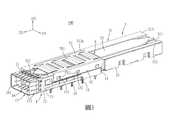
本發明之其他的特徵及功效,將於參照圖式的實施方式中清楚地呈現,其中:圖1是本發明連接器組件的一實施例的一立體圖,圖中兩個連接器組件設置在一電路板並被一機殼的一前蓋罩設;圖2是圖1的一立體分解圖;圖3是該實施例的一立體圖,圖中省略該實施例的插座連接器;圖4是圖3的一立體分解圖;圖5是該實施例的一俯視圖;圖6是沿圖5中的VI-VI線所截取的一局部剖視圖;圖7是該實施例的散熱器以及導熱墊片的立體分解圖,圖中省略散熱器的散熱鰭片;圖8是視角不同於圖7的一立體分解圖;圖9是類似圖6的一局部剖視圖,圖中一可插拔模組插設於該實施例;以及圖10是本實施例自底部觀看的一立體圖,圖中省略該實施例的屏蔽殼體的底壁以及插座連接器。Other features and effects of the present invention will be clearly presented in the embodiments with reference to the drawings, in which: FIG. 1 is a perspective view of an embodiment of the connector assembly of the present invention, in which two connector assemblies are arranged in one The circuit board is covered by a front cover of a housing; Figure 2 is a perspective exploded view of Figure 1; Figure 3 is a perspective view of this embodiment, the socket connector of this embodiment is omitted from the figure; Figure 4 is a diagram 3 is a three-dimensional exploded view; Figure 5 is a top view of this embodiment; Figure 6 is a partial cross-sectional view taken along the VI-VI line in Figure 5; Figure 7 is the heat sink and thermal pad of this embodiment 3D exploded view, omitting the heat sink fins; Fig. 8 is a 3D exploded view with a different perspective from Fig. 7; Fig. 9 is a partial cross-sectional view similar to Fig. 6, in which a pluggable module is inserted in This embodiment; and FIG. 10 is a perspective view of this embodiment viewed from the bottom, and the bottom wall of the shielding shell and the socket connector of this embodiment are omitted in the figure.

在本發明被詳細描述之前,應當注意在以下的說明內容中,類似的元件是以相同的編號來表示。Before the present invention is described in detail, it should be noted that in the following description, similar elements are denoted by the same numbers.

參閱圖1至圖4,本發明連接器組件100之一實施例,適用於與一可插拔模組200(見圖9)插接,且適用於設置在一電路板300並被一機殼400的一前蓋401罩設,本處以兩個連接器組件100間隔地並排設置於該電路板300且被該機殼400的前蓋401罩設作為示例,該電路板300於該兩連接器組件100之間處還設有與該兩連接器組件100並排的一散熱件500。該連接器組件100包含一屏蔽殼體1、一插座連接器2、一散熱器3、一導熱墊片4,以及一扣具5。1 to 4, an embodiment of theconnector assembly 100 of the present invention is suitable for plugging in a pluggable module 200 (see FIG. 9), and is suitable for being installed on acircuit board 300 and being covered by a housing Afront cover 401 of the 400 is covered. Here, twoconnector assemblies 100 are arranged side by side on thecircuit board 300 at intervals and are covered by thefront cover 401 of thecasing 400 as an example. Thecircuit board 300 is mounted on the two connectors. Aheat dissipating member 500 parallel to the twoconnector assemblies 100 is also arranged between thecomponents 100. Theconnector assembly 100 includes a shieldingshell 1, asocket connector 2, aheat sink 3, athermal pad 4, and afastener 5.

該屏蔽殼體1舉例來說可以為金屬材質,該屏蔽殼體1沿一前後方向D1延伸並具有一頂壁11、與該頂壁11沿一上下方向D2間隔相對的一底壁12、沿著一左右方向D3彼此間隔相對並分別連接於該頂壁11與該底壁12兩側的兩個側壁13、位於後端且連接於該頂壁11與該等側壁13後緣的一後壁14,以及自該等側壁13與該後壁14朝下延伸並適用於固定在該電路板300上及/或連接到接地軌跡的多個插腳15,該底壁12在本實施例中形成有向下凸出的多個凸包121。該屏蔽殼體1還具有由該頂壁11、該底壁12、該兩側壁13與該後壁14共同界定且位於內部的一容置腔16、位於前端且連通於該容置腔16並供該可插拔模組200插入的一插口161、沿該前後方向D1朝後延伸地形成於該頂壁11且連通該容置腔16的一開窗162,以及位於該底壁12後側且連通該容置腔16的一底部開口163。該機殼400的前蓋401罩設於該兩連接器組件100與該電路板300的前部,且該前蓋401形成有分別供該兩連接器組件100的前端伸出的兩個前端開口401a。該屏蔽殼體1位於前端的該插口161處設有多個接地件17,所述接地件17具有自該插口161處朝後延伸且分布於該屏蔽殼體1外側與該屏蔽殼體1內側的多個彈性指部171,該等彈性指部171中位於該屏蔽殼體1外側者用於與該機殼400的前蓋401的前端開口401a處接觸,該等彈性指部171中位於該屏蔽殼體1內側者用於與該可插拔模組200(見圖9)接觸。The shieldingshell 1 can be made of metal, for example. The shieldingshell 1 extends in a front-to-rear direction D1 and has atop wall 11, abottom wall 12 spaced apart from thetop wall 11 in a vertical direction D2, and A left-right direction D3 is spaced apart from each other and is connected to the twoside walls 13 on both sides of thetop wall 11 and thebottom wall 12 respectively, and a rear wall at the rear end and connected to the rear edge of thetop wall 11 and theside walls 13 14, and a plurality ofpins 15 extending downward from theside walls 13 and therear wall 14 and suitable for being fixed on thecircuit board 300 and/or connected to the ground trace. Thebottom wall 12 is formed in this embodiment A plurality ofconvex hulls 121 protruding downward. The shieldingshell 1 also has a containingcavity 16 which is defined by thetop wall 11, thebottom wall 12, the twoside walls 13 and therear wall 14 and is located inside, and is located at the front end and communicates with the containingcavity 16 and Asocket 161 into which thepluggable module 200 is inserted, anopening 162 formed on thetop wall 11 extending backwards along the front-to-rear direction D1 and communicating with theaccommodating cavity 16, and located on the rear side of thebottom wall 12 And connected to a bottom opening of theaccommodating cavity 16口163. Thefront cover 401 of thecasing 400 is arranged on the front of the twoconnector assemblies 100 and thecircuit board 300, and thefront cover 401 is formed with two front end openings respectively for extending the front ends of the twoconnector assemblies 100 401a. The shieldingshell 1 is provided with a plurality of groundingmembers 17 at thesocket 161 at the front end. The groundingmembers 17 have a rearward extension from thesocket 161 and are distributed on the outer side of the shieldingcase 1 and the inner side of the shieldingcase 1 Theelastic fingers 171 located outside the shieldingcase 1 are used to contact thefront opening 401a of thefront cover 401 of thecasing 400, and theelastic fingers 171 are located in the The inner side of the shieldingshell 1 is used to contact the pluggable module 200 (see FIG. 9).

參閱圖2及圖5至圖6,該插座連接器2設於該容置腔16的後段,且該插座連接器2具有一殼體21,以及多個端子22,該殼體21具有朝向該插口161的一插接槽211,每一端子22有位於該插接槽211內的一接觸部221,以及電性且機械地連接於前述的電路板300的一尾部222,詳細來說,該插座連接器2是設置於該電路板300,且通過該底部開口163地以該屏蔽殼體1罩蓋,以使該插座連接器2設於該容置腔16,但不以此為限。該屏蔽殼體1的開窗162朝後延伸至露出該插座連接器2的頂面處,且延伸至該屏蔽殼體1的後端的該後壁14以在該後壁14的上緣形成一凹口141。也就是說,該屏蔽殼體1的開窗162穿過該屏蔽殼體1的該後壁14,以在該後壁14的上緣形成一凹口141。2 and 5 to 6, thesocket connector 2 is disposed in the rear section of theaccommodating cavity 16, and thesocket connector 2 has ahousing 21 and a plurality ofterminals 22, and thehousing 21 has a direction facing theAn insertion slot 211 of thesocket 161, each terminal 22 has acontact portion 221 located in theinsertion slot 211, and is electrically and mechanically connected to atail portion 222 of theaforementioned circuit board 300. In detail, the Thereceptacle connector 2 is disposed on thecircuit board 300, and is covered by the shieldingshell 1 through thebottom opening 163, so that thereceptacle connector 2 is disposed in theaccommodating cavity 16, but not limited to this. Thewindow 162 of the shieldingshell 1 extends rearward to expose the top surface of thesocket connector 2 and extends to therear wall 14 at the rear end of the shieldingshell 1 to form an upper edge of therear wall 14Notch 141. In other words, thewindow 162 of the shieldingcase 1 penetrates therear wall 14 of the shieldingcase 1 to form anotch 141 on the upper edge of therear wall 14.

參閱圖1、圖4、圖6至圖9,該散熱器3設於該屏蔽殼體1形成有該開窗162的該頂壁11。該散熱器3包括一基板31、一熱管32,以及多個散熱鰭片33。該基板31舉例而言材質為金屬,該基板31設於該頂壁11且具有呈朝下凹陷狀並通過該開窗162向下伸入該容置腔16的一底板部311、連接於該底板部311的前緣且設於該頂壁11的頂面的一前翼部312、連接於該底板部311的兩側緣且設於該頂壁11的頂面的兩側翼部313,以及連接於該底板部311與該前翼部312之間且傾斜地延伸形成以用以導引該可插拔模組200插入的一導引部314。該熱管32在本實施例中為扁平式熱管32,該熱管32(又稱熱導管(Heat pipe))的扁平狀管體由高熱傳導效率的金屬材料(例如銅)製成,其內部具有填充有作動流體(例如純水)的封閉腔體,藉由封閉腔體內作動流體持續循環的液汽二相變化,使該熱管32呈現快速均溫的特性而達到快速導熱的作用。該熱管32設置在朝下凹陷的該底板部311的頂面,且該底板部311與該熱管32筆直地朝後延伸出該屏蔽殼體1的後端一段距離,該熱管32舉例來說可以焊接方式設置於該底板部311,但不以此為限制。由於基板31的底板部311與設置於底板部311的頂面的熱管32通過開窗162伸入容置腔16,因此散熱器3能較為靠近可插拔模組200以增加散熱效率。並且,藉由屏蔽殼體1的頂壁11上朝後延伸至該後壁14以在該後壁的上緣形成凹口141的開窗162,使基板31的底板部311的底面直接靠近地面對位於容置腔16後段的插座連接器2,且使該基板31的底板部311與該熱管32能沿該開窗162朝後筆直地延伸出該屏蔽殼體1的後端一段距離,藉此能更進一步地增加散熱效率,並且,還能使該基板31的底板部311與該熱管32在製造上不需為了避開該後壁14而彎折。Referring to FIG. 1, FIG. 4, and FIG. 6 to FIG. 9, theheat sink 3 is disposed on thetop wall 11 of the shieldingshell 1 where thewindow 162 is formed. Theheat sink 3 includes asubstrate 31, aheat pipe 32, and a plurality ofheat dissipation fins 33. For example, thesubstrate 31 is made of metal. Thesubstrate 31 is disposed on thetop wall 11 and has abottom plate portion 311 that is recessed downward and extends downward into theaccommodating cavity 16 through theopening 162, and is connected to the Floor part 311Afront wing portion 312 on the top surface of thetop wall 11, afront wing portion 312 connected to the side edges of thebottom plate portion 311 and provided on the top surface of thetop wall 11, and afront wing portion 313 connected to the top surface of the top wall 11 A guidingportion 314 is formed between thebottom plate portion 311 and thefront wing portion 312 and extends obliquely to guide the insertion of thepluggable module 200. Theheat pipe 32 is aflat heat pipe 32 in this embodiment. The flat tube body of the heat pipe 32 (also known as a heat pipe (Heat pipe)) is made of a metal material with high thermal conductivity (such as copper), and has a filling inside. A closed cavity with an actuating fluid (such as pure water), through the continuous liquid-vapor two-phase change of the actuating fluid in the closed cavity, causes theheat pipe 32 to exhibit the characteristics of rapid temperature uniformity to achieve rapid heat conduction. Theheat pipe 32 is disposed on the top surface of thebottom plate portion 311 that is recessed downward, and thebottom plate portion 311 and theheat pipe 32 extend straight back out of the rear end of the shieldingshell 1 for a distance. Theheat pipe 32 can be, for example, The welding method is provided on thebottom plate portion 311, but it is not limited to this. Since thebottom plate portion 311 of thesubstrate 31 and theheat pipe 32 disposed on the top surface of thebottom plate portion 311 extend into theaccommodating cavity 16 through thewindow 162, theheat sink 3 can be closer to thepluggable module 200 to increase the heat dissipation efficiency. In addition, by extending thetop wall 11 of the shieldingcase 1 backwards to therear wall 14 to form anopening 162 of thenotch 141 on the upper edge of the rear wall, the bottom surface of thebottom plate portion 311 of thesubstrate 31 is directly close to the ground. Facing thesocket connector 2 located at the rear section of theaccommodating cavity 16, and enabling thebottom plate portion 311 of thesubstrate 31 and theheat pipe 32 to extend straight back from the rear end of the shieldingshell 1 along theopening 162, Therefore, the heat dissipation efficiency can be further increased, and thebottom plate portion 311 of thesubstrate 31 and theheat pipe 32 do not need to be bent in order to avoid therear wall 14 during manufacturing.

該可插拔模組200具有一殼件201,以及一插接電路板(圖未示)。該殼件201具有用以自該屏蔽殼體1的插口161插入該容置腔16的一插接部201a,該插接電路板設於該殼件201且自該殼件201的插接部201a突伸出,並用以插入該插座連接器2的插接槽211以與該等端子22的接觸部221電性連接,該殼件201的插接部201a的前端形成有位於該插接電路板上方的一定位端面201b。在本實施例中,該基板31的底板部311的底面的面對於該插座連接器2處設有朝下突伸且適用於擋止該可插拔模組200的定位端面201b的前擋部311a,以防止該可插拔模組200於插接時過度深入。且該底板部311的底面相對於該後壁14處設有朝下突伸的後擋部311b,所述後擋部311b在朝後的方向被該後壁14所限位,進而限位該散熱器3以防止該散熱器3朝後移動。詳細來說,該底板部311的底面設有在該前後方向D1上延伸且彼此並排並朝下突出的兩個凸條311c,該兩凸條311c的前端共同構成所述前擋部311a,該兩凸條311c的後端共同構成所述後擋部311b,該兩凸條311c舉例來說可以如同本第一實施例中經由板金沖壓方式向下沖壓而突出地形成,也可以是以焊接方式將該兩凸條311c焊接於該底板部311的底面,需要說明的是,在其他變化實施態樣中,凸條311c也可以是一個或三個以上。此外,所述前擋部311a與所述後擋部311b並不限以凸條311c構成,換句話說,所述前擋部311a與所述後擋部311b也可以是以其他適合的結構構成。藉由將用以擋止可插拔模組200的所述前擋部311a與用以朝後地限位於該後壁14的所述後擋部311b設置於該基板31的底面,使該散熱器3藉由所述前擋部311a與所述後擋部311b更進一步地伸入該容置腔16內,也使該散熱器3更靠近該插座連接器2以更進一步加強散熱效率。Thepluggable module 200 has ahousing 201 and a plug-in circuit board (not shown). Thehousing 201 has a plug-inportion 201a for inserting into theaccommodating cavity 16 from thesocket 161 of the shieldingshell 1, and the plug-in circuit board is disposed on thehousing 201 and extends from the plug-in portion of thehousing 201 201a sticks out and usesTo be inserted into theinsertion slot 211 of thesocket connector 2 to be electrically connected to thecontact portions 221 of theterminals 22, the front end of theinsertion portion 201a of thehousing 201 is formed with a positioning end surface located above the insertion circuit board 201b. In this embodiment, the bottom surface of thebottom plate portion 311 of thesubstrate 31 is provided with a front stopper portion protruding downwards to thesocket connector 2 and suitable for blocking the positioning end surface 201b of thepluggable module 200 311a, to prevent thepluggable module 200 from being excessively deep during insertion. And the bottom surface of thebottom plate portion 311 is provided with arear stop portion 311b protruding downward relative to therear wall 14. Therear stop portion 311b is restricted by therear wall 14 in the rearward direction, thereby restricting the Theradiator 3 prevents theradiator 3 from moving backward. In detail, the bottom surface of thebottom plate portion 311 is provided with two protrudingstrips 311c extending in the front-rear direction D1, side by side and protruding downwards. The front ends of the two protrudingstrips 311c together constitute thefront stop portion 311a. The rear ends of the two protrudingbars 311c jointly constitute therear stop 311b. The two protrudingbars 311c can be formed by punching down and protruding downwards, for example, as in the first embodiment, or by welding. The two protrudingstrips 311c are welded to the bottom surface of thebottom plate portion 311. It should be noted that in other modified implementations, the number of protrudingstrips 311c may also be one or more than three. In addition, thefront stop portion 311a and therear stop portion 311b are not limited to be formed by protrudingstrips 311c. In other words, thefront stop portion 311a and therear stop portion 311b may also be constructed with other suitable structures. . Thefront blocking portion 311a for blocking thepluggable module 200 and therear blocking portion 311b for blocking therear wall 14 rearwardly are provided on the bottom surface of thesubstrate 31 to enable the heat dissipation Theradiator 3 is further extended into theaccommodating cavity 16 through thefront blocking portion 311a and therear blocking portion 311b, which also brings theheat sink 3 closer to thesocket connector 2 to further enhance the heat dissipation efficiency.

參閱圖1、圖2、圖4及圖10,該等散熱鰭片33概呈板狀且沿前後方向D1彼此平行排佈地相互扣合地連接,該等散熱鰭片33位於該屏蔽殼體1的側壁13的外側與該屏蔽殼體1的後壁14的後側,且該等散熱鰭片33設置於該基板31的底板部311與側翼部313的底面。該等散熱鰭片33舉例來說可以是以焊接方式設於該基板31,但在其他實施態樣中,該等散熱鰭片33也可以為非相互扣合的結構且為一體構造地形成於該基板31,不以此為限制。藉由該等散熱鰭片33可以加強該散熱器3的散熱效能。1, 2, 4 and 10, theheat dissipation fins 33 are generally plate-shaped and arranged parallel to each other along the front-rear direction D1 and are connected to each other in a snap-fit manner. Theheat dissipation fins 33 are located in the shieldingshell 1 ofThe outer side of theside wall 13 and the rear side of therear wall 14 of the shieldingcase 1, and theheat dissipation fins 33 are disposed on the bottom surface of thebottom plate portion 311 and theside wing portion 313 of thebase plate 31. The heat-dissipatingfins 33 may be provided on thesubstrate 31 by welding, for example, but in other embodiments, the heat-dissipatingfins 33 may also be non-interlocking structures and formed in an integral structure. Thesubstrate 31 is not limited to this. The heat dissipation efficiency of theheat sink 3 can be enhanced by theheat dissipation fins 33.

參閱圖1、圖4及圖7至圖9,該基板31的底板部311貫穿地形成有朝該容置腔16露出該熱管32的一底開口311d。該導熱墊片4通過該底開口311d設於該熱管32,該導熱墊片4適用於接觸自該插口161插入該容置腔16的該可插拔模組200。該導熱墊片4舉例來說為熱界面材料(Thermal Interface Material),舉例來說可以選自具有高導熱性、高柔韌性、可壓縮特性、絕緣性、耐磨性等的組合材料,且其也可通過材料的組合變化同時具備電磁波屏蔽作用(EMI Shielding)。此外,該導熱墊片4還可以為底材與相變化材料(phase change material)的組合結構。在本實施例中,該導熱墊片4覆蓋該底開口311d地設置在扁平的該熱管32的底表面與該基板31上。該導熱墊片4具有對應配合地設置在該熱管32的底面的一本體41,以及自該本體41在該左右方向D3上的兩側朝外延伸且設於該基板31的兩側翼部313的鄰近該底開口311d的內側緣處的兩設置部42,其中該兩設置部42在本實施例中是設於該兩側翼部313的內側緣處的底面,但在其他變化實施態樣中,該兩設置部42也可以是設置於該兩側翼部313的頂面,不以此為限制。該本體41與該兩設置部42舉例來說可以透過黏接劑(例如導熱膠)分別黏貼設置於該熱管32與該基板31的兩側翼部313的底面,需要說明的是,其中該本體41也可以不透過黏接劑黏貼於該熱管32而僅靠抵於該熱管32的底面。藉由介於扁平式的熱管32與可插拔模組200之間的導熱墊片4,避免兩個金屬面(熱管32與可插拔模組200之表面)之間不容易完全貼合的問題,其能加大熱管32與可插拔模組200之間的熱接觸面積並補償熱管32與可插拔模組200之間的間隙,進而將可插拔模組200產生的熱經由導熱墊片4高效地傳導至熱管32上,以加快導熱的速度並增加散熱效率。Referring to FIGS. 1, 4, and FIGS. 7-9, thebottom plate portion 311 of thesubstrate 31 is formed with abottom opening 311 d that exposes theheat pipe 32 toward theaccommodating cavity 16. The thermallyconductive gasket 4 is disposed on theheat pipe 32 through thebottom opening 311 d, and the thermallyconductive gasket 4 is suitable for contacting thepluggable module 200 inserted into theaccommodating cavity 16 from thesocket 161. The thermallyconductive gasket 4 is, for example, a thermal interface material (Thermal Interface Material), for example, can be selected from a combination of materials with high thermal conductivity, high flexibility, compressibility, insulation, wear resistance, etc., and its It can also have the effect of EMI Shielding at the same time by changing the combination of materials. In addition, the thermallyconductive gasket 4 can also be a combined structure of a substrate and a phase change material. In this embodiment, the thermallyconductive gasket 4 is disposed on the bottom surface of theflat heat pipe 32 and thesubstrate 31 so as to cover thebottom opening 311d. The thermallyconductive gasket 4 has abody 41 correspondingly arranged on the bottom surface of theheat pipe 32, and abody 41 extending outward from both sides of thebody 41 in the left-right direction D3 and arranged on bothside wings 313 of thesubstrate 31 Two settingportions 42 adjacent to the inner side edge of thebottom opening 311d, wherein the two settingportions 42 are provided on the bottom surface of the inner side edge of the twoside wings 313 in this embodiment, but in other modified embodiments, The twosetting portions 42 may also be provided on the top surface of the twoside wings 313, and it is not limited thereto. Themain body 41 and the two settingportions 42 can be attached to the bottom surfaces of the twoside wings 313 of theheat pipe 32 and thesubstrate 31, for example, through an adhesive (such as a thermal conductive glue).It is clear that themain body 41 can also be attached to theheat pipe 32 without passing through an adhesive, but only abuts against the bottom surface of theheat pipe 32. With the thermallyconductive gasket 4 between theflat heat pipe 32 and thepluggable module 200, the problem that the two metal surfaces (the surface of theheat pipe 32 and the pluggable module 200) are not easily fully bonded is avoided , Which can increase the thermal contact area between theheat pipe 32 and thepluggable module 200 and compensate the gap between theheat pipe 32 and thepluggable module 200, and then transfer the heat generated by thepluggable module 200 through the thermal pad Thesheet 4 is efficiently conducted to theheat pipe 32 to accelerate the speed of heat conduction and increase the heat dissipation efficiency.

該扣具5用以彈性地壓抵該散熱器3且使該散熱器3可相對於該開窗162移動地安裝於該屏蔽殼體1的該頂壁11,且該扣具5扣接於該屏蔽殼體1。該扣具5具有壓抵該散熱器3的基板31的一壓抵板51,以及自該壓抵板51的兩側朝下延伸的兩扣接板52。該基板31的其中一側翼部313形成供其中一扣接板52穿伸的一開縫313a,該等扣接板52分別扣接於該屏蔽殼體1的該等側壁13,通過開縫313a與扣接板52彼此之間的限位關係可以限制散熱器3的基板31的前後位置。該壓抵板51具有呈彈片狀且用以彈性地朝下壓抵於該散熱器3的多個彈性壓制部511,該等彈性壓制部511也可以是除了彈片結構以外的能壓抵該基板31的其他結構,不以本實施例為限制。該屏蔽殼體1的每一側壁13分別形成有朝外突出的多個扣片131,每一扣接板52還形成有與對應的側壁13的該等扣片131對應扣接的多個扣孔521,藉此使該扣具5能扣接於該屏蔽殼體1,並使該散熱器3被扣具5的彈性壓制部511向下且彈性地壓抵組裝於該屏蔽殼體1,該散熱器3的基板31的前翼部312及兩側翼部313則分別靠在開窗162前方及左右兩側的頂壁11上。並且,在本實施例中該扣具5的彈性壓制部511是直接壓抵接觸於該散熱器3的熱管32,藉此能使該屏蔽殼體1的熱能能經由扣合於該屏蔽殼體1的該扣具5傳遞至該散熱基座的熱管32以加強散熱效率。如圖9所示,藉由彈性地朝下壓抵於該散熱器3的該等彈性壓制部511,使當該可插拔模組200自該屏蔽殼體1的插口161插入該容置腔16時,該散熱器3能被該可插拔模組200向上頂抵以相對於該開窗162彈性地朝上移動。藉此能夠確保該可插拔模組200與設置於該散熱器3的該導熱墊片4之間彼此靠抵且互相接觸,以確保該散熱器3能協同該可插拔模組200散熱。另外,藉由該壓抵板51本身的板體能夠限位該散熱器3朝上移動時的最高位置。Thebuckle 5 is used for elastically pressing theradiator 3 so that theradiator 3 is movably installed on thetop wall 11 of the shieldingshell 1 relative to thewindow 162, and thebuckle 5 is buckled on The shieldingcase 1. Thebuckle 5 has apressing plate 51 pressed against thebase plate 31 of theheat sink 3, and two bucklingplates 52 extending downward from both sides of thepressing plate 51. One side of thewing portion 313 of thebase plate 31 is formed with aslit 313a through which one of thebuckle plates 52 penetrates. Thebuckle plates 52 are respectively buckled to theside walls 13 of the shieldingshell 1 through theslits 313a. The position-limiting relationship with thebuckle plate 52 can limit the front and rear positions of thebase plate 31 of theheat sink 3. Thepressing plate 51 has a plurality of elasticpressing parts 511 in the shape of elastic sheets and used to elastically press down against theheat sink 3. The elasticpressing parts 511 may also be capable of pressing against the elastic sheet structure. Other structures of thesubstrate 31 are not limited to this embodiment. Eachside wall 13 of the shieldingshell 1 is respectively formed with a plurality ofbuckles 131 protruding outward, and eachbuckle plate 52 is also formed with a plurality of buckles corresponding to thebuckles 131 of thecorresponding side wall 13. Thehole 521 enables thefastener 5 to be fastened to the shieldingshell 1, and theheat sink 3 is pressed downward and elastically pressed against the shieldingshell 1 by the elasticpressing portion 511 of thefastener 5, Thefront wing portion 312 and theside wing portions 313 of thebase plate 31 of theheat sink 3 are respectively leaned on thetop wall 11 in front of thewindow 162 and on the left and right sides. Moreover, in this embodiment, the elasticpressing portion 511 of thebuckle 5 directly presses and contacts withTheheat pipe 32 of theradiator 3 can thereby enable the heat energy of the shieldingshell 1 to be transferred to theheat pipe 32 of the heat dissipation base via thefastener 5 fastened to the shieldingshell 1 to enhance the heat dissipation efficiency. As shown in FIG. 9, by elastically pressing down against the elasticpressing portions 511 of theheat sink 3, thepluggable module 200 is inserted into the accommodating cavity from thesocket 161 of the shieldingshell 1. At 16 o'clock, theradiator 3 can be pushed upward by thepluggable module 200 to elastically move upward relative to thewindow 162. Thereby, it can be ensured that thepluggable module 200 and thethermal pad 4 provided on theheat sink 3 abut against and contact each other, so as to ensure that theheat sink 3 can cooperate with thepluggable module 200 to dissipate heat. In addition, the highest position of theheat sink 3 when theheat sink 3 moves upward can be restricted by the plate body of thepressing plate 51 itself.

綜上所述,本發明的扁平式的熱管32設置在呈凹陷狀且通過開窗162伸入容置腔16的底板部311上,導熱墊片4通過底板部311的底開口311d設置在熱管32且適用於接觸自插口161插入容置腔16的可插拔模組200(熱源),藉由介於熱管32與可插拔模組200之間的導熱墊片4,能加大熱管32與可插拔模組200之間的熱接觸面積並補償熱管32與可插拔模組200之間的間隙,進而將可插拔模組200產生的熱經由導熱墊片4高效地傳導至熱管32上,以加快導熱的速度並增加散熱效率。另外,由於基板31的底板部311與熱管32通過開窗162伸入容置腔16,因此散熱器3能較為靠近可插拔模組200以增加散熱效率。並且,藉由屏蔽殼體1的頂壁11上朝後延伸至該後壁14以在該後壁的上緣形成凹口141的開窗162,使基板31的底板部311的底面直接靠近地面對位於容置腔16後段的插座連接器2,且使該基板31的底板部311與該熱管32能沿該開窗162朝後筆直地延伸出該屏蔽殼體1的後端一段距離,藉此能更進一步地增加散熱效率。In summary, theflat heat pipe 32 of the present invention is arranged on thebottom plate portion 311 that is recessed and extends into theaccommodating cavity 16 through thewindow 162, and theheat conducting pad 4 is placed on the heat pipe through thebottom opening 311d of thebottom plate portion 311. 32 and is suitable for contacting the pluggable module 200 (heat source) inserted into theaccommodating cavity 16 from thesocket 161. Theheat conducting gasket 4 between theheat pipe 32 and thepluggable module 200 can enlarge theheat pipe 32 and The thermal contact area between thepluggable modules 200 and the gap between theheat pipe 32 and thepluggable module 200 are compensated, and the heat generated by thepluggable module 200 is efficiently transferred to theheat pipe 32 through thethermal pad 4 To speed up heat conduction and increase heat dissipation efficiency. In addition, since thebottom plate portion 311 of thesubstrate 31 and theheat pipe 32 extend into theaccommodating cavity 16 through thewindow 162, theheat sink 3 can be closer to thepluggable module 200 to increase the heat dissipation efficiency. In addition, by extending thetop wall 11 of the shieldingcase 1 backwards to therear wall 14 to form anopening 162 of thenotch 141 on the upper edge of the rear wall, the bottom surface of thebottom plate portion 311 of thesubstrate 31 is directly close to the ground. Facing thesocket connector 2 located at the rear section of theaccommodating cavity 16, and enabling thebottom plate portion 311 of thesubstrate 31 and theheat pipe 32 to extend straight back from the rear end of the shieldingshell 1 along theopening 162, This can further increase the heat dissipation efficiency.

惟以上所述者,僅為本發明之實施例而已,當不能以此限定本發明實施之範圍,凡是依本發明申請專利範圍及專利說明書內容所作之簡單的等效變化與修飾,皆仍屬本發明專利涵蓋之範圍內。However, the above are only examples of the present invention. When the scope of implementation of the present invention cannot be limited by this, all simple equivalent changes and modifications made in accordance with the scope of the patent application of the present invention and the content of the patent specification still belong to This invention patent covers the scope.

100:連接器組件100: connector assembly

1:屏蔽殼體1: Shielding shell

11:頂壁11: top wall

12:底壁12: bottom wall

121:凸包121: Convex Hull

13:側壁13: side wall

131:扣片131: Clasp

14:後壁14: back wall

141:凹口141: Notch

15:插腳15: pin

16:容置腔16: containing cavity

161:插口161: Socket

162:開窗162: open window

163:底部開口163: bottom opening

17:接地件17: Grounding piece

171:彈性指部171: Elastic Fingers

3:散熱器3: radiator

31:基板31: substrate

311:底板部311: bottom plate

311d:底開口311d: bottom opening

312:前翼部312: Front Wing

313:側翼部313: Flanking

313a:開縫313a: slit

314:導引部314: Guiding Department

32:熱管32: heat pipe

33:散熱鰭片33: cooling fins

4:導熱墊片4: Thermal pad

41:本體41: body

42:設置部42: Setting Department

5:扣具5: Buckle

51:壓抵板51: pressure plate

511:彈性壓制部511: Elastic pressing part

52:扣接板52: buckle plate

521:扣孔521: Buttonhole

D1:前後方向D1: front and rear direction

D2:上下方向D2: Up and down direction

D3:左右方向D3: Left and right direction

Claims (7)

Translated fromChinese
一種連接器組件,包含:一屏蔽殼體,具有位於內部的一容置腔、位於前端且連通於該容置腔的一插口,以及形成該屏蔽殼體的一壁且連通該容置腔的一開窗;一插座連接器,設於該容置腔;一散熱器,設於該屏蔽殼體形成有該開窗的該壁,該散熱器包括一基板,以及一熱管,該基板具有呈凹陷狀並通過該開窗向下伸入該容置腔的一底板部,該熱管設置於該底板部上,該底板部形成有朝該容置腔露出該熱管的一底開口;以及一導熱墊片,通過該底開口設於該熱管,該導熱墊片適用於接觸自該插口插入該容置腔的一可插拔模組。A connector assembly includes: a shielding shell with an accommodating cavity located inside, a socket at the front end and communicating with the accommodating cavity, and a wall forming the shielding shell and communicating with the accommodating cavity A window; a socket connector arranged in the accommodating cavity; a radiator arranged on the wall of the shielding shell on which the window is formed; the radiator includes a substrate and a heat pipe; the substrate has a shape A bottom plate portion of the accommodating cavity that is recessed and extends downward through the window, the heat pipe is disposed on the bottom plate portion, and the bottom plate portion is formed with a bottom opening exposing the heat pipe toward the accommodating cavity; and a heat conduction The gasket is arranged on the heat pipe through the bottom opening, and the heat-conducting gasket is suitable for contacting a pluggable module inserted into the containing cavity from the socket.如請求項1所述的連接器組件,其中,該熱管為扁平式熱管,該導熱墊片覆蓋該底開口地設置在該熱管的底表面與該基板上。The connector assembly according to claim 1, wherein the heat pipe is a flat heat pipe, and the thermally conductive gasket is disposed on the bottom surface of the heat pipe and the substrate so as to cover the bottom opening.如請求項2所述的連接器組件,其中,該插座連接器設於該容置腔的後段,該屏蔽殼體的開窗朝後延伸至露出該插座連接器,該基板的底板部的底面直接面對該插座連接器。The connector assembly according to claim 2, wherein the receptacle connector is disposed in the rear section of the accommodating cavity, the window of the shielding shell extends backward to expose the receptacle connector, and the bottom surface of the bottom plate of the substrate Face the socket connector directly.如請求項3所述的連接器組件,其中,該屏蔽殼體的後端設有一後壁,該開窗朝後延伸至該後壁以在該後壁的上緣形成一凹口,該基板的底板部與該熱管沿該開窗朝後筆直地延伸出該屏蔽殼體的後端一段距離。The connector assembly according to claim 3, wherein the rear end of the shielding shell is provided with a rear wall, the opening extends backward to the rear wall to form a notch on the upper edge of the rear wall, and the base plate The bottom plate part of the heat pipe extends straight from the rear end of the shielding shell along the window.如請求項4所述的連接器組件,其中,該底板部的底面的面對於該插座連接器處設有朝下突伸且適用於擋止該可插拔模組的前擋部,該底板部的底面相對於該後壁處設有朝下突伸的後擋部,所述後擋部在朝後的方向被該後壁所限位。The connector assembly according to claim 4, wherein the bottom surface of the bottom plate portion is provided with a front stop portion that protrudes downward toward the socket connector and is suitable for blocking the pluggable module, and the bottom plate The bottom surface of the part is provided with a rear stop protruding downward relative to the rear wall, and the rear stopThe part is restricted by the rear wall in the rearward direction.如請求項1至5中任一項所述的連接器組件,其中,該基板還具有連接於該底板部且設於該壁的一前翼部及兩側翼部,以及連接於該底板部與該前翼部之間且傾斜地延伸形成的一導引部。The connector assembly according to any one of claims 1 to 5, wherein the substrate further has a front wing portion and two side wing portions connected to the bottom plate portion and provided on the wall, and connected to the bottom plate portion and A guiding part is formed between the front wing parts and extending obliquely.如請求項1所述的連接器組件,其中,還包含用以彈性地壓抵該散熱器且使該散熱器可相對於該開窗移動地安裝於該屏蔽殼體的該壁的一扣具,該扣具扣接於該屏蔽殼體。The connector assembly according to claim 1, further comprising a fastener for elastically pressing the radiator and enabling the radiator to be movably mounted on the wall of the shielding shell with respect to the window , The buckle is buckled to the shielding shell.
TW108141795A2019-11-182019-11-18 Connector assemblyTWI722665B (en)

Priority Applications (1)

Application NumberPriority DateFiling DateTitle
TW108141795ATWI722665B (en)2019-11-182019-11-18 Connector assembly

Applications Claiming Priority (1)

Application NumberPriority DateFiling DateTitle
TW108141795ATWI722665B (en)2019-11-182019-11-18 Connector assembly

Publications (2)

Publication NumberPublication Date
TWI722665Btrue TWI722665B (en)2021-03-21
TW202121761A TW202121761A (en)2021-06-01

Family

ID=76036107

Family Applications (1)

Application NumberTitlePriority DateFiling Date
TW108141795ATWI722665B (en)2019-11-182019-11-18 Connector assembly

Country Status (1)

CountryLink
TW (1)TWI722665B (en)

Families Citing this family (1)

* Cited by examiner, † Cited by third party
Publication numberPriority datePublication dateAssigneeTitle
CN116027496B (en)*2021-10-272025-07-22讯凯国际股份有限公司Heat dissipation structure using heat pipe to conduct heat

Citations (4)

* Cited by examiner, † Cited by third party
Publication numberPriority datePublication dateAssigneeTitle
CN100483857C (en)*2004-03-032009-04-29泰科电子公司Pluggable electronic receptacle with heat sink assembly
US20180039411A1 (en)*2016-08-022018-02-08Cnex Labs, Inc.Method and Apparatus for Providing Data Storage and Network Communication Using an Auxiliary Plug
TW201929646A (en)*2017-01-122019-07-16美商山姆科技公司Cage with an attached heatsink
TW201937818A (en)*2018-01-232019-09-16美商太谷康奈特提威提公司Receptacle assembly and thermal-transfer assembly

Patent Citations (4)

* Cited by examiner, † Cited by third party
Publication numberPriority datePublication dateAssigneeTitle
CN100483857C (en)*2004-03-032009-04-29泰科电子公司Pluggable electronic receptacle with heat sink assembly
US20180039411A1 (en)*2016-08-022018-02-08Cnex Labs, Inc.Method and Apparatus for Providing Data Storage and Network Communication Using an Auxiliary Plug
TW201929646A (en)*2017-01-122019-07-16美商山姆科技公司Cage with an attached heatsink
TW201937818A (en)*2018-01-232019-09-16美商太谷康奈特提威提公司Receptacle assembly and thermal-transfer assembly

Also Published As

Publication numberPublication date
TW202121761A (en)2021-06-01

Similar Documents

PublicationPublication DateTitle
US11567276B2 (en)Shield cage assembly
CN104979678B (en)Connector shell component and there is its connector
CN112217029B (en)Connector assembly
US11553622B2 (en)Connector assembly
CN110799026B (en) shield assembly
TWM574818U (en)Shield cover assembly
CN112531371B (en)Connector assembly
TWI733519B (en) Connector assembly
TW202109992A (en)Heat dissipation case and electrical connector module
TWI708442B (en) Connector assembly
TWI763212B (en) connector assembly
CN205985532U (en)Electric connector combination
CN113937540B (en) Connector components
TWI722665B (en) Connector assembly
TWI763385B (en) connector assembly
US11792958B2 (en)Connector assembly
TW202228341A (en)Liquid-cooled connector assembly including a guide shield, a liquid-cooled disk, at least one heat-conducting plate, and a compression spring
CN112821122B (en)Connector assembly
TWI802272B (en) connector assembly
TW202318739A (en)Connector assembly including a shielding cover, a heat sink and a buckle
TWI737017B (en) Shield assembly
TWM593081U (en)Connector assembly
TWI717837B (en)Connector assembly
CN113809600B (en) Guide shield and connector assembly
TWM643329U (en)connector assembly

[8]ページ先頭

©2009-2025 Movatter.jp