TWI721533B - Tremor identification method and system thereof - Google Patents
Tremor identification method and system thereofDownload PDFInfo
- Publication number
- TWI721533B TWI721533BTW108129442ATW108129442ATWI721533BTW I721533 BTWI721533 BTW I721533BTW 108129442 ATW108129442 ATW 108129442ATW 108129442 ATW108129442 ATW 108129442ATW I721533 BTWI721533 BTW I721533B
- Authority
- TW
- Taiwan
- Prior art keywords
- intersection
- jitter
- optical pattern
- images
- type
- Prior art date
Links
Images


Classifications
- A—HUMAN NECESSITIES
- A61—MEDICAL OR VETERINARY SCIENCE; HYGIENE
- A61B—DIAGNOSIS; SURGERY; IDENTIFICATION
- A61B5/00—Measuring for diagnostic purposes; Identification of persons
- A61B5/103—Measuring devices for testing the shape, pattern, colour, size or movement of the body or parts thereof, for diagnostic purposes
- A61B5/11—Measuring movement of the entire body or parts thereof, e.g. head or hand tremor or mobility of a limb
- A61B5/1101—Detecting tremor
- A—HUMAN NECESSITIES
- A61—MEDICAL OR VETERINARY SCIENCE; HYGIENE
- A61B—DIAGNOSIS; SURGERY; IDENTIFICATION
- A61B5/00—Measuring for diagnostic purposes; Identification of persons
- A61B5/0059—Measuring for diagnostic purposes; Identification of persons using light, e.g. diagnosis by transillumination, diascopy, fluorescence
- A61B5/0077—Devices for viewing the surface of the body, e.g. camera, magnifying lens
- A—HUMAN NECESSITIES
- A61—MEDICAL OR VETERINARY SCIENCE; HYGIENE
- A61B—DIAGNOSIS; SURGERY; IDENTIFICATION
- A61B5/00—Measuring for diagnostic purposes; Identification of persons
- A61B5/103—Measuring devices for testing the shape, pattern, colour, size or movement of the body or parts thereof, for diagnostic purposes
- A61B5/11—Measuring movement of the entire body or parts thereof, e.g. head or hand tremor or mobility of a limb
- A61B5/1126—Measuring movement of the entire body or parts thereof, e.g. head or hand tremor or mobility of a limb using a particular sensing technique
- A61B5/1128—Measuring movement of the entire body or parts thereof, e.g. head or hand tremor or mobility of a limb using a particular sensing technique using image analysis
- A—HUMAN NECESSITIES
- A61—MEDICAL OR VETERINARY SCIENCE; HYGIENE
- A61B—DIAGNOSIS; SURGERY; IDENTIFICATION
- A61B5/00—Measuring for diagnostic purposes; Identification of persons
- A61B5/72—Signal processing specially adapted for physiological signals or for diagnostic purposes
- A61B5/7235—Details of waveform analysis
- A61B5/7253—Details of waveform analysis characterised by using transforms
- A61B5/7257—Details of waveform analysis characterised by using transforms using Fourier transforms
- A—HUMAN NECESSITIES
- A61—MEDICAL OR VETERINARY SCIENCE; HYGIENE
- A61B—DIAGNOSIS; SURGERY; IDENTIFICATION
- A61B5/00—Measuring for diagnostic purposes; Identification of persons
- A61B5/72—Signal processing specially adapted for physiological signals or for diagnostic purposes
- A61B5/7235—Details of waveform analysis
- A61B5/7264—Classification of physiological signals or data, e.g. using neural networks, statistical classifiers, expert systems or fuzzy systems
- A61B5/7267—Classification of physiological signals or data, e.g. using neural networks, statistical classifiers, expert systems or fuzzy systems involving training the classification device
- G—PHYSICS
- G06—COMPUTING OR CALCULATING; COUNTING
- G06N—COMPUTING ARRANGEMENTS BASED ON SPECIFIC COMPUTATIONAL MODELS
- G06N20/00—Machine learning
- G—PHYSICS
- G06—COMPUTING OR CALCULATING; COUNTING
- G06T—IMAGE DATA PROCESSING OR GENERATION, IN GENERAL
- G06T7/00—Image analysis
- G06T7/0002—Inspection of images, e.g. flaw detection
- G06T7/0012—Biomedical image inspection
- G06T7/0014—Biomedical image inspection using an image reference approach
- G—PHYSICS
- G06—COMPUTING OR CALCULATING; COUNTING
- G06T—IMAGE DATA PROCESSING OR GENERATION, IN GENERAL
- G06T7/00—Image analysis
- G06T7/20—Analysis of motion
- G06T7/262—Analysis of motion using transform domain methods, e.g. Fourier domain methods
Landscapes
- Health & Medical Sciences (AREA)
- Engineering & Computer Science (AREA)
- Life Sciences & Earth Sciences (AREA)
- Physics & Mathematics (AREA)
- Medical Informatics (AREA)
- General Health & Medical Sciences (AREA)
- Public Health (AREA)
- Veterinary Medicine (AREA)
- Animal Behavior & Ethology (AREA)
- Surgery (AREA)
- Molecular Biology (AREA)
- Heart & Thoracic Surgery (AREA)
- Biomedical Technology (AREA)
- Pathology (AREA)
- Biophysics (AREA)
- Computer Vision & Pattern Recognition (AREA)
- Physiology (AREA)
- Artificial Intelligence (AREA)
- Dentistry (AREA)
- Oral & Maxillofacial Surgery (AREA)
- Mathematical Physics (AREA)
- Theoretical Computer Science (AREA)
- Radiology & Medical Imaging (AREA)
- Nuclear Medicine, Radiotherapy & Molecular Imaging (AREA)
- General Physics & Mathematics (AREA)
- Signal Processing (AREA)
- Psychiatry (AREA)
- Evolutionary Computation (AREA)
- Software Systems (AREA)
- Fuzzy Systems (AREA)
- Data Mining & Analysis (AREA)
- General Engineering & Computer Science (AREA)
- Multimedia (AREA)
- Computing Systems (AREA)
- Quality & Reliability (AREA)
- Measurement Of The Respiration, Hearing Ability, Form, And Blood Characteristics Of Living Organisms (AREA)
Abstract
Description
Translated fromChinese本發明是有關於一種辨識方法及其系統,且特別是有關於一種抖動辨識方法及其系統。The present invention relates to an identification method and system, and more particularly to a jitter identification method and system.
巴金森氏症(Parkinson’s disease,PD)是一種常見的神經系統變性疾病,其臨床表現包括靜止性震抖動、運動遲緩、肌強直和姿勢步態障礙,同時病人可能伴有抑鬱、便秘和睡眠障礙等非運動症狀。在上述臨床表現中,靜止性震顫抖動(resting tremor)是最常見的症狀,但較難以肉眼觀察到相關的抖動情形。Parkinson's disease (PD) is a common neurodegenerative disease. Its clinical manifestations include static tremor, bradykinesia, muscle rigidity and postural and gait disorders. At the same time, the patient may be accompanied by depression, constipation, and sleep disorders And other non-motor symptoms. Among the above clinical manifestations, resting tremor (resting tremor) is the most common symptom, but it is difficult to observe the related tremor with the naked eye.
在PD的相關研究中,多半是基於核磁共振成像(Magnetic Resonance Imaging,MRI)、單光子發射計算機斷層檢查(Single Photon Emission Computed Tomography,SPECT)、正子斷層造影(Positron Emission Tomography,PET)等高效能醫學影像來進行。然而,由於上述醫學影像在使用上不但具較高的成本,且亦會產生相關的輻射問題,故較難用於作為日常追蹤及治療效果評估的手段。In PD related research, most of them are based on high performance such as Magnetic Resonance Imaging (MRI), Single Photon Emission Computed Tomography (SPECT), Positron Emission Tomography (PET), etc. Medical imaging. However, because the above-mentioned medical images not only have a higher cost in use, but also cause related radiation problems, it is difficult to use them as a means of daily tracking and treatment effect evaluation.
有鑑於此,本發明提供一種抖動辨識方法及其系統,其可用於解決上述技術問題。In view of this, the present invention provides a jitter identification method and system thereof, which can be used to solve the above technical problems.
本發明提供一種抖動辨識方法,包括:投影一第一光學圖樣至一待測部位,以在待測部位上相應地形成一第二光學圖樣,其中第二光學圖樣經合成以包括至少一交叉點;對待測部位上的第二光學圖樣拍攝多個影像,並基於前述影像取得各交叉點的一動態特徵;以及基於各交叉點的動態特徵辨識待測部位的一抖動態樣。The present invention provides a method for recognizing jitter, including: projecting a first optical pattern to a part to be measured to correspondingly form a second optical pattern on the part to be measured, wherein the second optical pattern is synthesized to include at least one intersection ; Take multiple images of the second optical pattern on the part to be measured, and obtain a dynamic feature of each intersection based on the aforementioned images; and identify the dynamic pattern of the part to be measured based on the dynamic characteristics of each intersection.
本發明一種抖動辨識系統,包括投影裝置、取像裝置及處理裝置。處理裝置耦接於取像裝置及投影裝置之間,並經配置以:控制投影裝置投影一第一光學圖樣至一待測部位,以在待測部位上相應地形成一第二光學圖樣,其中第二光學圖樣經合成以包括至少一交叉點;控制取像裝置對待測部位上的第二光學圖樣拍攝多個影像,並基於前述影像取得各交叉點的一動態特徵;以及基於各交叉點的動態特徵辨識待測部位的一抖動態樣。The present invention is a jitter identification system, which includes a projection device, an image capturing device and a processing device. The processing device is coupled between the image capturing device and the projection device, and is configured to: control the projection device to project a first optical pattern to a part to be measured, so as to form a second optical pattern on the part to be measured accordingly, wherein The second optical pattern is synthesized to include at least one intersection; the imaging device is controlled to take a plurality of images of the second optical pattern on the part to be measured, and a dynamic feature of each intersection is obtained based on the aforementioned images; and based on each intersection The dynamic feature identifies the flicking dynamic sample of the part to be tested.
基於上述,本發明提出的抖動辨識方法及其系統可基於投影於待測部位上的第二光學圖樣中交叉點的動態特徵來辨識待測部位的抖動態樣。藉此,可提供一種即時、低成本、非侵入性的抖動辨識機制。Based on the above, the jitter identification method and system proposed by the present invention can identify the jitter dynamics of the test site based on the dynamic characteristics of the intersection in the second optical pattern projected on the test site. In this way, a real-time, low-cost, non-invasive jitter identification mechanism can be provided.
為讓本發明的上述特徵和優點能更明顯易懂,下文特舉實施例,並配合所附圖式作詳細說明如下。In order to make the above-mentioned features and advantages of the present invention more comprehensible, the following specific embodiments are described in detail in conjunction with the accompanying drawings.
概略而言,本發明可在將具有交叉點的第一光學圖樣投射至待測部位上以形成第二光學圖樣之後,觀察第二光學圖樣上的交叉點隨著待測部位的移動而呈現的動態特徵,並由人工智慧模型據以辨識待測部位的抖動態樣。在相關應用中,由於PD患者身上出現的抖動態樣將有別於未患有PD的患者,因此在以PD患者/非PD患者的抖動態樣訓練上述人工智慧模型之後,即可讓人工智慧模型基於未知患者的抖動態樣來辨識未知患者為PD患者/非PD患者。以下將作進一步說明。Generally speaking, the present invention can be used to observe the cross point on the second optical pattern as the part to be measured moves after the first optical pattern with the intersection point is projected onto the part to be measured to form the second optical pattern. Dynamic characteristics, and the artificial intelligence model is used to identify the shaking dynamics of the part to be tested. In related applications, since the tremor patterns in PD patients will be different from those without PD, after training the above artificial intelligence model with PD patients/non-PD patients’ tremor patterns, artificial intelligence can be used. The model identifies the unknown patient as a PD patient/non-PD patient based on the shaking motion of the unknown patient. This will be further explained below.
請參照圖1,其是依據本發明之一實施例繪示的辨識待測部位抖動態樣的示意圖。在圖1中,抖動辨識系統100包括投影裝置102、取像裝置104及處理裝置106。在不同的實施例中,投影裝置102例如是數位光學處理(Digital Light Processing,DLP)投影機或是其他類似的投影裝置,並可受控於處理裝置106而將指定的圖樣投射至指定的物體上。Please refer to FIG. 1, which is a schematic diagram of identifying the shaking motion of a part to be measured according to an embodiment of the present invention. In FIG. 1, the
以圖1為例,投影裝置102可受控於處理裝置106而將第一光學圖樣120投影至待測部位199(例如,手部)上。在本實施例中,第一光學圖樣120例如是摩爾紋(Moire),但本發明可不限於此。在其他實施例中,投影裝置102亦可投射具有其他態樣的圖樣作為第一光學圖樣120,只要其具有至少一個交叉點即可。在其他實施例中,亦可採用不具有任何交叉點的圖樣作為第一光學圖樣120,例如數條平行線等,但可不限於此。Taking FIG. 1 as an example, the
取像裝置104例如是任何具有電荷耦合元件(Charge coupled device,CCD)鏡頭、互補式金氧半電晶體(Complementary metal oxide semiconductor transistors,CMOS)鏡頭的攝影機,但本發明可不限於此。The image capturing
在本實施例中,當第一光學圖樣120被投影至待測部位199上時,第一光學圖樣120將因應於待測部位199的輪廓而產生變形的現象,從而在待測部位199上形成第二光學圖樣130。在此情況下,取像裝置104可受控於處理裝置106而對第二光學圖樣130連續地拍攝多張影像。In this embodiment, when the first
在圖1中,由於第一光學圖樣120中可包括一或多個交叉點,因此在第一光學圖樣120被投影至待測部位199上之後,將相應地使得第二光學圖樣130亦經合成以包括一或多個交叉點(例如交叉點130a,如圖1所示。詳細而言,在第一光學圖樣120被投影至待測部位199上後,可在待測部位199上形成陰影,而此陰影可與第一光學圖樣120重疊、干涉,進而產生第二光學圖樣130(其例如呈現等高線的態樣)。In FIG. 1, since the first
在此情況下,若待測部位199出現抖動(tremor)的情況,將使得第二光學圖樣130上的各交叉點在上述影像中的位置出現變化。因此,可藉由追蹤第二光學圖樣130上的各交叉點在前述影像中的位置變化而相應地推得待測部位199的抖動情況,但本發明可不限於此。In this case, if a tremor occurs in the part to be measured 199, the position of each intersection on the second
此外,在其他實施例中,若第一光學圖樣係實現為不具交叉點的態樣(例如一或多條平行線),則在第一光學圖樣被投影至待測部位199上後,可在待測部位199上形成另一種陰影(例如一或多條平行線),而此陰影可與第一光學圖樣重疊、干涉,進而產生第二光學圖樣,但本發明可不限於此。In addition, in other embodiments, if the first optical pattern is implemented as a pattern without intersections (for example, one or more parallel lines), after the first optical pattern is projected onto the part to be measured 199, Another shadow (for example, one or more parallel lines) is formed on the part to be measured 199, and the shadow may overlap and interfere with the first optical pattern, thereby generating a second optical pattern, but the present invention is not limited to this.
處理裝置106耦接於投影裝置102及取像裝置104,並可以是為手機、智慧型手機、個人電腦(personal computer,PC)、筆記型電腦(notebook PC)、網本型電腦(netbook PC)、平板電腦(tablet PC),但本發明可不限於此。應了解的是,雖投影裝置102、取像裝置104及處理裝置106在圖1中係繪示為三個不同的裝置,但在其他的實施例中,此三者亦可整合為單一個裝置。The
請參照圖2,其是依據本發明之一實施例繪示的抖動辨識方法流程圖。本實施例的方法可由圖1的抖動辨識系統100執行,以下即搭配圖1所示的元件來說明圖2各步驟的細節。Please refer to FIG. 2, which is a flowchart of a jitter identification method according to an embodiment of the present invention. The method of this embodiment can be executed by the
首先,在步驟S210中,處理裝置106可控制投影裝置102投影第一光學圖樣120至待測部位199,以在待測部位199上相應地形成第二光學圖樣130。承先前實施例所述的,在第一光學圖樣120包括至少一個交叉點的情況下,形成於待測部位199上的第二光學圖樣130亦會包括至少一個交叉點(例如交叉點130a)。在本實施例中,待測部位199例如是一未知患者的手部,但可不限於此。First, in step S210, the
接著,在步驟S220中,處理裝置106可控制取像裝置104對待測部位199上的第二光學圖樣130拍攝多個影像,並基於前述影像取得各交叉點的動態特徵。Next, in step S220, the
在不同的實施例中,各交叉點的動態特徵可表徵為各交叉點的振幅、形狀、抖動頻率等,但本發明可不限於此。為便於說明,以下將基僅於第二光學圖樣130中的交叉點130a進行說明,而本領域具通常知識者應可依相關教示而推得處理裝置106基於第二光學圖樣130中的其他交叉點所進行的操作。In different embodiments, the dynamic characteristics of each cross point may be characterized as the amplitude, shape, and jitter frequency of each cross point, but the present invention may not be limited thereto. For ease of description, the following description will be based only on the
在一實施例中,處理裝置106可基於快速傅利葉轉換(Fast Fourier Transform,FFT)取得交叉點130a在取像裝置104所拍攝的影像中的抖動頻率。在另一實施例中,處理裝置106可取得交叉點130a在上述影像中的多個位置,並藉由分析前述位置的變化情形以得知交叉點130a的振幅,即交叉點130a在前述影像中的移動幅度。In an embodiment, the
之後,在步驟S230中,處理裝置106可基於各交叉點的動態特徵辨識待測部位199的抖動態樣。在一實施例中,處理裝置106可將各交叉點的動態特徵輸入至先前提及的人工智慧模型以辨識待測部位199的抖動態樣係屬於第一類抖動或第二類抖動。After that, in step S230, the
為讓上述人工智慧模型具有辨識待測部位199的抖動態樣的能力,處理裝置106可預先以多個訓練影像訓練上述人工智慧模型,其中上述訓練影像包括多個第一類影像及多個第二類影像,其中上述第一類影像對應於該第一類抖動,上述第二類影像對應於第二類抖動。In order for the artificial intelligence model to have the ability to recognize the shaking motion of the
在一實施例中,若欲讓上述人工智慧模型具有辨識PD的能力,則上述第一類影像可拍攝自患有PD的一或多個第一患者,而上述第二類影像可拍攝自未患有PD的一或多個第二患者。舉例來說,若待測部位199為一未知患者的手部,則第一類影像可以是各第一患者的手部影像,而第二類影像則可以是各第二患者的手部影像。在此情況下,人工智慧模型即可從第一類影像中學習到患有PD的第一患者的手部抖動態樣(即,第一類抖動),以及從第二類影像中學習到未患有PD的第二患者的手部抖動態樣(即,第二類抖動)。In one embodiment, if the artificial intelligence model is to have the ability to recognize PD, the first type of images can be taken from one or more first patients suffering from PD, and the second type of images can be taken from the future. One or more second patients with PD. For example, if the part to be tested 199 is the hand of an unknown patient, the first type of image may be the hand image of each first patient, and the second type of image may be the hand image of each second patient. In this case, the artificial intelligence model can learn from the first type of images the hand shaking dynamics of the first patient with PD (that is, the first type of shaking), and learn from the second type of images. The hand shaking of the second patient with PD is dynamic (ie, the second type of shaking).
此外,在人工智慧模型的訓練階段中,處理裝置106可控制投影裝置102投影第一光學圖樣120至第一患者(即,PD患者)的第一預設部位,以在第一預設部位上相應地形成第三光學圖樣(即,隨著第一預設部位的輪廓而變形的第一光學圖樣120)。在本實施例中,第三光學圖樣包括至少一第一交叉點,且第一預設部位對應於待測部位(例如,皆為手部)。之後,處理裝置106可控制取像裝置104對第一預設部位上的第三光學圖樣拍攝影像以作為上述第一類影像,並基於所拍攝的第一類影像取得各第一交叉點的抖動頻率。之後,處理裝置106可取得各第一交叉點的抖動頻率的一頻率峰值,並將各第一交叉點及對應的頻率峰值映射至第一標準部位圖以產生第一抖動分布圖。接著,處理裝置106可將第一抖動分布圖標記為第一類抖動,並饋入人工智慧模型以供人工智慧模型學習第一類抖動的特徵。In addition, in the training phase of the artificial intelligence model, the
相似地,處理裝置106可控制投影裝置102投影第一光學圖樣120至第二患者(即,非PD患者)的第二預設部位,以在第二預設部位上相應地形成第四光學圖樣(即,隨著第二預設部位的輪廓而變形的第一光學圖樣120)。在本實施例中,第四光學圖樣包括至少一第二交叉點,且第二預設部位對應於待測部位(例如,皆為手部)。之後,處理裝置106可控制取像裝置104對第二預設部位上的第四光學圖樣拍攝影像以作為上述第二類影像,並基於所拍攝的第二類影像取得各第二交叉點的抖動頻率。之後,處理裝置106可取得各第二交叉點的抖動頻率的一頻率峰值,並將各第二交叉點及對應的頻率峰值映射至第二標準部位圖以產生第二抖動分布圖。接著,處理裝置106可將第二抖動分布圖標記為第二類抖動,並饋入人工智慧模型以供人工智慧模型學習第二類抖動的特徵。Similarly, the
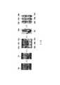
為讓上述概念更為清楚,以下另輔以圖3進行說明。請參照圖3,其是依據本發明之一實施例繪示的標記訓練資料的示意圖。在本實施例中,假設PD患者將其第一預設部位399(即,手部)置放於本發明的投影裝置(未繪示)之下,而本發明的處理裝置(未繪示)可相應地控制投影裝置將第一光學圖樣投影至第一預設部位399,以在第一預設部位399上形成第三光學圖樣310。之後,處理裝置可基於取像裝置(未繪示)對第一預設部位399所拍攝的多張第一類影像來取得第三光學圖樣310上各第一交叉點的動態特徵。以第三光學圖樣310上的第一交叉點310a、310b、310c為例,處理裝置可將第一交叉點310a~310c的動態特徵表徵為各第一交叉點310a~310c的抖動頻率。In order to make the above concept clearer, the following description is supplemented with FIG. 3. Please refer to FIG. 3, which is a schematic diagram of marking training data according to an embodiment of the present invention. In this embodiment, it is assumed that the PD patient places his first predetermined part 399 (ie, hand) under the projection device (not shown) of the present invention, and the processing device (not shown) of the present invention The projection device can be controlled accordingly to project the first optical pattern to the first
在圖3中,圖表320a、320b、320c分別可以是第一交叉點310a~310c經FFT而得的抖動頻率分布圖,但本發明可不限於此。In FIG. 3, the
之後,處理裝置可取得各第一交叉點的抖動頻率的頻率峰值,並將各第一交叉點及其頻率峰值映射至第一標準部位圖330以產生第一抖動分布圖330a,其中具不同頻率峰值的第一交叉點可標示有不同的顏色。之後,處理裝置可將第一抖動分布圖330a標記為第一類抖動(即,PD患者的抖動),並饋入人工智慧模型以供人工智慧模型學習第一類抖動的特徵。After that, the processing device can obtain the frequency peak of the jitter frequency of each first cross point, and map each first cross point and its frequency peak to the first
相似地,本發明的抖動辨識系統亦可對其他的第一患者(例如,PD患者)進行上述操作,以產生第一抖動分布圖330b、330c。之後,本發明的抖動辨識系統可將第一抖動分布圖330b、330c標記為第一類抖動(即,PD患者的抖動),並饋入人工智慧模型以供人工智慧模型學習第一類抖動的特徵。Similarly, the jitter identification system of the present invention can also perform the above operations on other first patients (for example, PD patients) to generate the first jitter distribution maps 330b and 330c. After that, the jitter identification system of the present invention can mark the first jitter distribution maps 330b and 330c as the first type of jitter (ie, the jitter of the PD patient), and feed it into the artificial intelligence model for the artificial intelligence model to learn the first type of jitter feature.
此外,本發明的抖動辨識系統亦可對其他的第二患者(例如,非PD患者)進行上述操作,以產生第二抖動分布圖330d、330e、330f。之後,本發明的抖動辨識系統可將第二抖動分布圖330d、330e、330f標記為第二類抖動(即,非PD患者的抖動),並饋入人工智慧模型以供人工智慧模型學習第二類抖動的特徵。In addition, the jitter identification system of the present invention can also perform the above operations on other second patients (for example, non-PD patients) to generate second
在完成對人工智慧模型的訓練之後,處理裝置106即可將各交叉點的動態特徵(例如振幅、抖動頻率等)輸入人工智慧模型。舉例而言,處理裝置106可將各交叉點及其抖動頻率的頻率峰值亦映射至可饋入人工智慧模型的一標準部位圖,以在此標準部位圖上形成對應於待測部位199的抖動分布圖。After completing the training of the artificial intelligence model, the
之後,人工智慧模型即可據以辨識待測部位199(即,未知患者的手部)的抖動態樣是屬於第一類抖動或第二類抖動。若待測部位199的抖動態樣屬於第一類抖動,即代表未知患者可能患有PD。相反地,若待測部位199的抖動態樣屬於第二類抖動,即代表未知患者可能未患有PD。After that, the artificial intelligence model can identify whether the shaking motion of the part to be measured 199 (ie, the hand of an unknown patient) belongs to the first type of shaking or the second type of shaking. If the shaking motion of the
簡言之,在將PD患者/非PD患者的手部抖動態樣作為訓練資料來訓練人工智慧模型之後,此人工智慧模型即可基於未知患者手部抖動態樣來辨識未知患者是否患有PD,但本發明可不限於此。在其他實施例中,處理裝置106亦可基於PD患者/非PD患者其他部位的抖動態樣來訓練人工智慧模型,而不限於上述實施例中提及的手部。In short, after the hand tremor motion patterns of PD patients/non-PD patients are used as training data to train the artificial intelligence model, the artificial intelligence model can identify whether the unknown patient has PD based on the hand tremor motion patterns of the unknown patient , But the present invention may not be limited to this. In other embodiments, the
在一些實施例中,本發明的概念可適用於辨識其他型態的待測部位的抖動態樣,舉凡植物、人類以外的其他動物、礦物等都可作為本發明所考慮的待測部位。在此情況下,本發明的系統可對人工智慧模型進行相應的訓練,從而讓其具有辨識植物、動物及礦物的抖動態樣的能力。相關細節可參照先前實施例中的說明,於此不另贅述。In some embodiments, the concept of the present invention can be applied to identify other types of shaking patterns of the tested parts. For example, plants, animals other than humans, minerals, etc. can be used as the tested parts considered in the present invention. In this case, the system of the present invention can perform corresponding training on the artificial intelligence model, so that it has the ability to recognize the shaking behavior of plants, animals, and minerals. For related details, please refer to the description in the previous embodiment, which will not be repeated here.
綜上所述,本發明提出的抖動辨識方法及其系統可在將具有交叉點的第一光學圖樣投射至待測部位上以形成第二光學圖樣之後,觀察第二光學圖樣上的交叉點的動態特徵,並由人工智慧模型據以辨識待測部位的抖動態樣是屬於第一類抖動或第二類抖動。藉此,可提供一種即時、低成本、非侵入性、非接觸式的抖動辨識機制。並且,透過對人工智慧模型進行適當的訓練,可讓人工智慧模型具備辨識特定疾病(例如,PD)的能力,因此可有效地作為日常追蹤及治療效果評估的手段。並且,透過本發明提出的方法,還可在PD患者的抖動尚不明顯時即協助醫師作出相關的診斷,因而能夠讓相關的醫護人員採取對應的治療手段,從而有利於病情的控制。In summary, the jitter identification method and system proposed by the present invention can project the first optical pattern with the intersection point onto the part to be measured to form the second optical pattern, and then observe the position of the intersection on the second optical pattern. Dynamic characteristics, and the artificial intelligence model is used to identify whether the jitter motion of the part to be measured belongs to the first type of jitter or the second type of jitter. In this way, a real-time, low-cost, non-invasive, non-contact jitter identification mechanism can be provided. In addition, by properly training the artificial intelligence model, the artificial intelligence model can be equipped with the ability to identify specific diseases (for example, PD), so it can be effectively used as a means of daily tracking and treatment effect evaluation. In addition, the method proposed by the present invention can also assist physicians in making relevant diagnoses when the shaking of PD patients is not obvious, so that relevant medical staff can adopt corresponding treatment methods, which is conducive to disease control.
此外,對於患有典型PD(即,抖動為肉眼可見)或非典型PD(即,抖動不為肉眼可見)的患者而言,本發明皆可用以協助辨識其身上待測部位的抖動態樣。進一步而言,即便患者的抖動情形因服藥後而有所減緩,但仍可藉由本發明的方法及其系統觀察到改善後餘存的微小振動模式(tremor pattern),進而有助於醫師作出相關的診斷。In addition, for patients suffering from typical PD (that is, the shaking is visible to the naked eye) or atypical PD (that is, the shaking is not visible to the naked eye), the present invention can be used to help identify the shaking motion of the body to be tested. Furthermore, even if the patient’s tremor is reduced after taking the medication, the method and system of the present invention can still observe the remaining small vibration pattern (tremor pattern) after improvement, which will help the physician to make relevant The diagnosis.
並且,本發明還可用於辨識植物、動物、礦物等各式待測部位的抖動態樣,因而可用於協助相關的研究人員對所考慮的待測部位進行研究。In addition, the present invention can also be used to identify the shaking dynamics of various parts to be tested, such as plants, animals, minerals, etc., and thus can be used to assist relevant researchers in researching the part to be tested under consideration.
雖然本發明已以實施例揭露如上,然其並非用以限定本發明,任何所屬技術領域中具有通常知識者,在不脫離本發明的精神和範圍內,當可作些許的更動與潤飾,故本發明的保護範圍當視後附的申請專利範圍所界定者為準。Although the present invention has been disclosed in the above embodiments, it is not intended to limit the present invention. Anyone with ordinary knowledge in the relevant technical field can make some changes and modifications without departing from the spirit and scope of the present invention. The scope of protection of the present invention shall be determined by the scope of the attached patent application.
100:抖動辨識系統 102:投影裝置 104:取像裝置 106:處理裝置 120:第一光學圖樣 130:第二光學圖樣 130a:交叉點 199:待測部位 310:第三光學圖樣 320a、320b、320c:圖表 330:第一標準部位圖 310a、310b、310c:第一交叉點 330a、330b、330c:第一抖動分布圖 330d、330e、330f:第二抖動分布圖 399:第一預設部位 S210~S230:步驟100: Jitter identification system 102: Projection device 104: Capture device 106: Processing device 120: The first optical pattern 130: second
圖1是依據本發明之一實施例繪示的辨識待測部位抖動態樣的示意圖。 圖2是依據本發明之一實施例繪示的抖動辨識方法流程圖。 圖3是依據本發明之一實施例繪示的標記訓練資料的示意圖。FIG. 1 is a schematic diagram of identifying the shaking motion of a part to be measured according to an embodiment of the present invention. FIG. 2 is a flowchart of a jitter identification method according to an embodiment of the present invention. FIG. 3 is a schematic diagram of marking training data according to an embodiment of the present invention.
S210~S230:步驟S210~S230: Steps
Claims (10)
Translated fromChinesePriority Applications (2)
| Application Number | Priority Date | Filing Date | Title |
|---|---|---|---|
| TW108129442ATWI721533B (en) | 2019-08-19 | 2019-08-19 | Tremor identification method and system thereof |
| US16/921,966US20210052195A1 (en) | 2019-08-19 | 2020-07-07 | Tremor identification method and system thereof |
Applications Claiming Priority (1)
| Application Number | Priority Date | Filing Date | Title |
|---|---|---|---|
| TW108129442ATWI721533B (en) | 2019-08-19 | 2019-08-19 | Tremor identification method and system thereof |
Publications (2)
| Publication Number | Publication Date |
|---|---|
| TW202109549A TW202109549A (en) | 2021-03-01 |
| TWI721533Btrue TWI721533B (en) | 2021-03-11 |
Family
ID=74647206
Family Applications (1)
| Application Number | Title | Priority Date | Filing Date |
|---|---|---|---|
| TW108129442ATWI721533B (en) | 2019-08-19 | 2019-08-19 | Tremor identification method and system thereof |
Country Status (2)
| Country | Link |
|---|---|
| US (1) | US20210052195A1 (en) |
| TW (1) | TWI721533B (en) |
Citations (3)
| Publication number | Priority date | Publication date | Assignee | Title |
|---|---|---|---|---|
| TWM522003U (en)* | 2016-01-13 | 2016-05-21 | Yi-Chun Lin | Monitoring and management system for care of patients with Parkinson's disease |
| CN105701806A (en)* | 2016-01-11 | 2016-06-22 | 上海交通大学 | Depth image-based Parkinson tremor motion characteristic detection method and system |
| CN109040573A (en)* | 2017-06-08 | 2018-12-18 | 株式会社理光 | Method of compensating for hand shake and blur correcting device |
Family Cites Families (11)
| Publication number | Priority date | Publication date | Assignee | Title |
|---|---|---|---|---|
| KR20080064155A (en)* | 2005-10-14 | 2008-07-08 | 어플라이드 리써치 어쏘시에이츠 뉴질랜드 리미티드 | Method and apparatus for monitoring surface features |
| WO2008130905A2 (en)* | 2007-04-17 | 2008-10-30 | Mikos, Ltd. | System and method for using three dimensional infrared imaging to provide detailed anatomical structure maps |
| EP2400261A1 (en)* | 2010-06-21 | 2011-12-28 | Leica Geosystems AG | Optical measurement method and system for determining 3D coordination in a measuring object surface |
| AU2012210593B2 (en)* | 2011-01-25 | 2016-12-08 | Novartis Ag | Systems and methods for medical use of motion imaging and capture |
| AU2013260650B2 (en)* | 2013-11-20 | 2015-07-16 | Canon Kabushiki Kaisha | Rotational phase unwrapping |
| US10083233B2 (en)* | 2014-09-09 | 2018-09-25 | Microsoft Technology Licensing, Llc | Video processing for motor task analysis |
| WO2017062994A1 (en)* | 2015-10-09 | 2017-04-13 | I2Dx, Inc. | System and method for non-invasive and non-contact measurement in early therapeutic intervention |
| CN207600393U (en)* | 2017-12-14 | 2018-07-10 | 北京驭光科技发展有限公司 | Pattern projection module, three-dimensional information obtain system and processing unit |
| EP3685729A1 (en)* | 2019-01-23 | 2020-07-29 | Universiteit Antwerpen | Method and apparatus for obtaining a 3d map of an eardrum |
| US11501441B2 (en)* | 2019-05-14 | 2022-11-15 | Aic Innovations Group, Inc. | Biomarker determination using optical flows |
| TWI714221B (en)* | 2019-08-19 | 2020-12-21 | 國立中央大學 | Transmissive light based tremor identification method and system thereof |
- 2019
- 2019-08-19TWTW108129442Apatent/TWI721533B/enactive
- 2020
- 2020-07-07USUS16/921,966patent/US20210052195A1/ennot_activeAbandoned
Patent Citations (3)
| Publication number | Priority date | Publication date | Assignee | Title |
|---|---|---|---|---|
| CN105701806A (en)* | 2016-01-11 | 2016-06-22 | 上海交通大学 | Depth image-based Parkinson tremor motion characteristic detection method and system |
| TWM522003U (en)* | 2016-01-13 | 2016-05-21 | Yi-Chun Lin | Monitoring and management system for care of patients with Parkinson's disease |
| CN109040573A (en)* | 2017-06-08 | 2018-12-18 | 株式会社理光 | Method of compensating for hand shake and blur correcting device |
Also Published As
| Publication number | Publication date |
|---|---|
| US20210052195A1 (en) | 2021-02-25 |
| TW202109549A (en) | 2021-03-01 |
Similar Documents
| Publication | Publication Date | Title |
|---|---|---|
| US11503998B1 (en) | Method and a system for detection of eye gaze-pattern abnormalities and related neurological diseases | |
| Chen et al. | Patient-specific pose estimation in clinical environments | |
| Li et al. | Appearance-based gaze estimation for ASD diagnosis | |
| Smith et al. | Gaze locking: passive eye contact detection for human-object interaction | |
| US20210004957A1 (en) | Systems and methods of measuring the body based on image analysis | |
| Poppe et al. | AMAB: Automated measurement and analysis of body motion | |
| US20180204379A1 (en) | System and Method for Providing Reconstruction of Human Surfaces from Orientation Data | |
| Abbasi et al. | Deep-learning for automated markerless tracking of infants general movements | |
| Romeo et al. | Video based mobility monitoring of elderly people using deep learning models | |
| Rahman et al. | Auto-gait: Automatic ataxia risk assessment with computer vision from gait task videos | |
| Yang et al. | Graph-based denoising for respiration and heart rate estimation during sleep in thermal video | |
| Naruniec et al. | Webcam‐based system for video‐oculography | |
| TWI714221B (en) | Transmissive light based tremor identification method and system thereof | |
| TWI721533B (en) | Tremor identification method and system thereof | |
| Weigle et al. | Analysis of eye-tracking experiments performed on a Tobii T60 | |
| TWM591390U (en) | Transmissive light based termor identification system thereof | |
| Cai et al. | Robust gaze estimation via normalized iris center-eye corner vector | |
| Alphonse et al. | Pain assessment from facial expression images utilizing Statistical Frei-Chen Mask (SFCM)-based features and DenseNet | |
| JP6922768B2 (en) | Information processing device | |
| TWI644285B (en) | Acupuncture visualization Chinese medicine system and method thereof by using AR technology | |
| Damale et al. | A low‐cost, autonomous gait detection and estimation system for analyzing gait impairments in mice | |
| Lowe | Ocular motion classification for mobile device presentation attack detection | |
| Caro et al. | Video and optoelectronics in movement disorders | |
| Pan et al. | mmcare: A nursing care activity monitoring system via mmwave sensing | |
| Hashem et al. | A smart wearable and assisted system for Alzheimer’s Patients |