TWI719893B - Digital self-injection-locked radar - Google Patents
Digital self-injection-locked radarDownload PDFInfo
- Publication number
- TWI719893B TWI719893BTW109114331ATW109114331ATWI719893BTW I719893 BTWI719893 BTW I719893BTW 109114331 ATW109114331 ATW 109114331ATW 109114331 ATW109114331 ATW 109114331ATW I719893 BTWI719893 BTW I719893B
- Authority
- TW
- Taiwan
- Prior art keywords
- digital
- signal
- analog
- injection
- self
- Prior art date
Links
Images


Classifications
- G—PHYSICS
- G01—MEASURING; TESTING
- G01S—RADIO DIRECTION-FINDING; RADIO NAVIGATION; DETERMINING DISTANCE OR VELOCITY BY USE OF RADIO WAVES; LOCATING OR PRESENCE-DETECTING BY USE OF THE REFLECTION OR RERADIATION OF RADIO WAVES; ANALOGOUS ARRANGEMENTS USING OTHER WAVES
- G01S7/00—Details of systems according to groups G01S13/00, G01S15/00, G01S17/00
- G01S7/02—Details of systems according to groups G01S13/00, G01S15/00, G01S17/00 of systems according to group G01S13/00
- G01S7/35—Details of non-pulse systems
- G01S7/352—Receivers
- G—PHYSICS
- G01—MEASURING; TESTING
- G01S—RADIO DIRECTION-FINDING; RADIO NAVIGATION; DETERMINING DISTANCE OR VELOCITY BY USE OF RADIO WAVES; LOCATING OR PRESENCE-DETECTING BY USE OF THE REFLECTION OR RERADIATION OF RADIO WAVES; ANALOGOUS ARRANGEMENTS USING OTHER WAVES
- G01S13/00—Systems using the reflection or reradiation of radio waves, e.g. radar systems; Analogous systems using reflection or reradiation of waves whose nature or wavelength is irrelevant or unspecified
- G01S13/02—Systems using reflection of radio waves, e.g. primary radar systems; Analogous systems
- G01S13/50—Systems of measurement based on relative movement of target
- G01S13/52—Discriminating between fixed and moving objects or between objects moving at different speeds
- G01S13/536—Discriminating between fixed and moving objects or between objects moving at different speeds using transmission of continuous unmodulated waves, amplitude-, frequency-, or phase-modulated waves
- A—HUMAN NECESSITIES
- A61—MEDICAL OR VETERINARY SCIENCE; HYGIENE
- A61B—DIAGNOSIS; SURGERY; IDENTIFICATION
- A61B5/00—Measuring for diagnostic purposes; Identification of persons
- A61B5/02—Detecting, measuring or recording for evaluating the cardiovascular system, e.g. pulse, heart rate, blood pressure or blood flow
- A61B5/024—Measuring pulse rate or heart rate
- A—HUMAN NECESSITIES
- A61—MEDICAL OR VETERINARY SCIENCE; HYGIENE
- A61B—DIAGNOSIS; SURGERY; IDENTIFICATION
- A61B5/00—Measuring for diagnostic purposes; Identification of persons
- A61B5/05—Detecting, measuring or recording for diagnosis by means of electric currents or magnetic fields; Measuring using microwaves or radio waves
- A61B5/0507—Detecting, measuring or recording for diagnosis by means of electric currents or magnetic fields; Measuring using microwaves or radio waves using microwaves or terahertz waves
- A—HUMAN NECESSITIES
- A61—MEDICAL OR VETERINARY SCIENCE; HYGIENE
- A61B—DIAGNOSIS; SURGERY; IDENTIFICATION
- A61B5/00—Measuring for diagnostic purposes; Identification of persons
- A61B5/103—Measuring devices for testing the shape, pattern, colour, size or movement of the body or parts thereof, for diagnostic purposes
- A61B5/11—Measuring movement of the entire body or parts thereof, e.g. head or hand tremor or mobility of a limb
- A61B5/113—Measuring movement of the entire body or parts thereof, e.g. head or hand tremor or mobility of a limb occurring during breathing
- A61B5/1135—Measuring movement of the entire body or parts thereof, e.g. head or hand tremor or mobility of a limb occurring during breathing by monitoring thoracic expansion
- A—HUMAN NECESSITIES
- A61—MEDICAL OR VETERINARY SCIENCE; HYGIENE
- A61B—DIAGNOSIS; SURGERY; IDENTIFICATION
- A61B5/00—Measuring for diagnostic purposes; Identification of persons
- A61B5/72—Signal processing specially adapted for physiological signals or for diagnostic purposes
- A61B5/7203—Signal processing specially adapted for physiological signals or for diagnostic purposes for noise prevention, reduction or removal
- G—PHYSICS
- G01—MEASURING; TESTING
- G01S—RADIO DIRECTION-FINDING; RADIO NAVIGATION; DETERMINING DISTANCE OR VELOCITY BY USE OF RADIO WAVES; LOCATING OR PRESENCE-DETECTING BY USE OF THE REFLECTION OR RERADIATION OF RADIO WAVES; ANALOGOUS ARRANGEMENTS USING OTHER WAVES
- G01S13/00—Systems using the reflection or reradiation of radio waves, e.g. radar systems; Analogous systems using reflection or reradiation of waves whose nature or wavelength is irrelevant or unspecified
- G01S13/86—Combinations of radar systems with non-radar systems, e.g. sonar, direction finder
- G01S13/862—Combination of radar systems with sonar systems
- G—PHYSICS
- G01—MEASURING; TESTING
- G01S—RADIO DIRECTION-FINDING; RADIO NAVIGATION; DETERMINING DISTANCE OR VELOCITY BY USE OF RADIO WAVES; LOCATING OR PRESENCE-DETECTING BY USE OF THE REFLECTION OR RERADIATION OF RADIO WAVES; ANALOGOUS ARRANGEMENTS USING OTHER WAVES
- G01S7/00—Details of systems according to groups G01S13/00, G01S15/00, G01S17/00
- G01S7/02—Details of systems according to groups G01S13/00, G01S15/00, G01S17/00 of systems according to group G01S13/00
- G01S7/35—Details of non-pulse systems
- G01S7/352—Receivers
- G01S7/354—Extracting wanted echo-signals
- G—PHYSICS
- G01—MEASURING; TESTING
- G01S—RADIO DIRECTION-FINDING; RADIO NAVIGATION; DETERMINING DISTANCE OR VELOCITY BY USE OF RADIO WAVES; LOCATING OR PRESENCE-DETECTING BY USE OF THE REFLECTION OR RERADIATION OF RADIO WAVES; ANALOGOUS ARRANGEMENTS USING OTHER WAVES
- G01S7/00—Details of systems according to groups G01S13/00, G01S15/00, G01S17/00
- G01S7/02—Details of systems according to groups G01S13/00, G01S15/00, G01S17/00 of systems according to group G01S13/00
- G01S7/41—Details of systems according to groups G01S13/00, G01S15/00, G01S17/00 of systems according to group G01S13/00 using analysis of echo signal for target characterisation; Target signature; Target cross-section
- G01S7/415—Identification of targets based on measurements of movement associated with the target
- A—HUMAN NECESSITIES
- A61—MEDICAL OR VETERINARY SCIENCE; HYGIENE
- A61B—DIAGNOSIS; SURGERY; IDENTIFICATION
- A61B5/00—Measuring for diagnostic purposes; Identification of persons
- A61B5/02—Detecting, measuring or recording for evaluating the cardiovascular system, e.g. pulse, heart rate, blood pressure or blood flow
- A61B5/0205—Simultaneously evaluating both cardiovascular conditions and different types of body conditions, e.g. heart and respiratory condition
- G—PHYSICS
- G01—MEASURING; TESTING
- G01S—RADIO DIRECTION-FINDING; RADIO NAVIGATION; DETERMINING DISTANCE OR VELOCITY BY USE OF RADIO WAVES; LOCATING OR PRESENCE-DETECTING BY USE OF THE REFLECTION OR RERADIATION OF RADIO WAVES; ANALOGOUS ARRANGEMENTS USING OTHER WAVES
- G01S13/00—Systems using the reflection or reradiation of radio waves, e.g. radar systems; Analogous systems using reflection or reradiation of waves whose nature or wavelength is irrelevant or unspecified
- G01S13/88—Radar or analogous systems specially adapted for specific applications
Landscapes
- Engineering & Computer Science (AREA)
- Health & Medical Sciences (AREA)
- Radar, Positioning & Navigation (AREA)
- Remote Sensing (AREA)
- Life Sciences & Earth Sciences (AREA)
- Physics & Mathematics (AREA)
- Computer Networks & Wireless Communication (AREA)
- General Physics & Mathematics (AREA)
- Pathology (AREA)
- Animal Behavior & Ethology (AREA)
- Veterinary Medicine (AREA)
- Public Health (AREA)
- Biophysics (AREA)
- General Health & Medical Sciences (AREA)
- Biomedical Technology (AREA)
- Heart & Thoracic Surgery (AREA)
- Medical Informatics (AREA)
- Molecular Biology (AREA)
- Surgery (AREA)
- Physiology (AREA)
- Signal Processing (AREA)
- Cardiology (AREA)
- Computer Vision & Pattern Recognition (AREA)
- Artificial Intelligence (AREA)
- Psychiatry (AREA)
- Dentistry (AREA)
- Oral & Maxillofacial Surgery (AREA)
- Nuclear Medicine, Radiotherapy & Molecular Imaging (AREA)
- Radiology & Medical Imaging (AREA)
- Radar Systems Or Details Thereof (AREA)
Abstract
Description
Translated fromChinese本發明是關於一種自我注入鎖定雷達,特別是關於一種數位自我注入鎖定雷達。The present invention relates to a self-injection locking radar, in particular to a digital self-injection locking radar.
自我注入鎖定雷達是一種低複雜度且高靈敏度的連續波雷達,相當適用於偵測生物體的生命徵象,自我注入鎖定雷達藉由偵測目標與發射天線之間的相對移動所發生的都普勒效應,由接收天線接收含有都普勒相移的反射訊號後注入振盪單元,使振盪單元處於自我注入鎖定狀態下的輸出訊號產生頻率調制,最後對振盪單元的輸出訊號進行頻率解調後即可得到生物體的移動位移。自我注入鎖定雷達具有高靈敏度,故能清楚偵測到生物體因呼吸及心跳等生命特徵造成的微小移動位移,然而由於自我注入鎖定雷達需要有效抑制注入訊號的雜訊才能確保高靈敏度表現,而且經常由於生物體的移動位移過大而造成偵測位移的失真,都可能是生命徵象偵測無法成功的原因。Self-injection locking radar is a low-complexity and high-sensitivity continuous wave radar, which is quite suitable for detecting vital signs of living organisms. Self-injection locking radar detects the relative movement between the target and the transmitting antenna. Leer effect, the receiving antenna receives the reflected signal containing the Doppler phase shift and injects it into the oscillation unit, so that the output signal of the oscillation unit in the self-injection lock state produces frequency modulation, and finally the output signal of the oscillation unit is frequency demodulated. The movement and displacement of the organism can be obtained. The self-injection lock radar has high sensitivity, so it can clearly detect the tiny movement and displacement of the living body due to vital signs such as breathing and heartbeat. However, the self-injection lock radar needs to effectively suppress the noise of the injected signal to ensure high-sensitivity performance, and Frequently, the distortion of the detection displacement caused by the excessive displacement of the biological body may be the reason for the failure of the vital sign detection.
本發明的主要目的是將自我注入鎖定雷達數位化,而具有可編程及設計彈性高之特性,能夠有效地抵抗注入訊號之雜訊並解決偵測位移之失真問題。The main purpose of the present invention is to digitize the self-injection locking radar, which has the characteristics of programmable and high design flexibility, which can effectively resist the noise of the injected signal and solve the distortion problem of the detected displacement.
本發明之一種數位自我注入鎖定雷達,其包含一數位自我注入鎖定振盪器、一無線訊號收發單元及一數位頻率解調單元,該數位自我注入鎖定振盪器輸出一數位輸出訊號,該無線訊號收發單元電性連接該數位自我注入鎖定振盪器以轉換該數位輸出訊號為一無線訊號並將該無線訊號發射至一目標,該目標反射一反射訊號,該無線訊號收發單元接收該反射訊號並輸出一數位注入訊號至該數位自我注入鎖定振盪器,使該數位自我注入鎖定振盪器處於一自我注入鎖定狀態(Self-injection-locked state)並產生一數位振盪訊號,該數位頻率解調單元電性連接該數位自我注入鎖定振盪器以接收該數位振盪訊號,且該數位頻率解調單元用以解調該數位振盪訊號為一數位解調訊號。A digital self-injection-locked radar of the present invention includes a digital self-injection-locked oscillator, a wireless signal transceiver unit and a digital frequency demodulation unit. The digital self-injection-locked oscillator outputs a digital output signal, and the wireless signal is transceived The unit is electrically connected to the digital self-injection locking oscillator to convert the digital output signal into a wireless signal and transmit the wireless signal to a target, the target reflects a reflected signal, and the wireless signal transceiver unit receives the reflected signal and outputs a Digitally inject a signal to the digital self-injection-locked oscillator so that the digital self-injection-locked oscillator is in a self-injection-locked state and generates a digital oscillation signal. The digital frequency demodulation unit is electrically connected The digital self-injection locked oscillator receives the digital oscillation signal, and the digital frequency demodulation unit is used to demodulate the digital oscillation signal into a digital demodulation signal.
本發明藉由將自我注入鎖定雷達數位化,能夠令該數位自我注入鎖定雷達對生物體移動位移之偵測上具有高靈敏度,並且具有可編程特性及高設計彈性,而具有極佳的抗雜訊與抗失真能力,能夠進一步地提高生命徵象偵測的效能。By digitizing the self-injection locking radar, the present invention can make the digital self-injection locking radar have high sensitivity in the detection of the movement and displacement of the biological body, and has programmable characteristics and high design flexibility, and has excellent anti-clutter Signal and anti-distortion capabilities can further improve the performance of vital signs detection.
請參閱第1圖,為本發明之一實施例,一種數位自我注入鎖定雷達100的功能方塊圖,該數位自我注入鎖定雷達100包含一數位自我注入鎖定振盪器110、一無線訊號收發單元120及一數位頻率解調單元130。該數位自我注入鎖定振盪器110產生一數位輸出訊號uout,該無線訊號收發單元120電性連接該數位自我注入鎖定振盪器110以接收該數位輸出訊號uout,該無線訊號收發單元120將該數位輸出訊號uout發射為一無線訊號Sw至一目標T,該目標T反射一反射訊號Sr,其中該無線訊號Sw及該反射訊號Sr可為電磁波訊號或超音波訊號,該無線訊號收發單元120接收該反射訊號Sr並輸出一數位注入訊號uinj至該數位自我注入鎖定振盪器110,使該數位自我注入鎖定振盪器110處於一自我注入鎖定狀態(Self-injection-locked state)而產生一數位振盪訊號u。Please refer to Figure 1, which is an embodiment of the present invention, a functional block diagram of a digital self-
該目標T與該無線訊號收發單元120有著一相對位移x時,該相對位移x會對該無線訊號Sw產生都普勒效應(Doppler Effect),使得該反射訊號Sr中含有該相對位移x造成的都普勒相移,因此,該數位注入訊號uinj亦包含有該相對位移x造成的都普勒相移,而該數位注入訊號uinj在注入該數位自我注入鎖定振盪器110時會對該數位振盪訊號u產生頻率調制,因此,該數位頻率解調單元130電性連接該數位自我注入鎖定振盪器110以接收該數位振盪訊號u,且該數位頻率解調單元130用以解調該數位振盪訊號u為一數位解調訊號w,該數位解調訊號w即包含有該相對位移x的資訊。When the target T and the wireless
請參閱第2圖,其為本發明之一第一實施例,在本實施例中,該數位自我注入鎖定振盪器110具有一數位諧振器111、一數位比較器112及一第一數位加法器113,該數位諧振器111輸出該數位振盪訊號u,該數位比較器112電性連接該數位諧振器111以接收該數位振盪訊號u,且該數位比較器112輸出該數位輸出訊號uout,該第一數位加法器113電性連接該數位比較器112及該無線訊號收發單元120以接收該數位輸出訊號uout及該數位注入訊號uinj,且該第一數位加法器113輸出一數位加法訊號u1至該數位諧振器111。較佳的,該數位諧振器111、該數位比較器112及該第一數位加法器113為整合於現場可程式化邏輯閘陣列(Field Programmable Gate Array, FPGA)中的數位元件,使該數位自我注入鎖定振盪器110具有良好的抗雜訊能力。Please refer to FIG. 2, which is a first embodiment of the present invention. In this embodiment, the digital self-injection locked
請參閱第2圖,在本實施例中,該無線訊號收發單元120具有一發射天線121、一接收天線122、一鏡像頻率抑制轉頻器123(Image reject frequency converter)、一第一數位類比轉換器124及一類比數位轉換器125,該第一數位類比轉換器124電性連接該數位比較器112以接收該數位輸出訊號uout,該第一數位類比轉換器124將該數位輸出訊號uout轉換為一低頻類比輸出訊號SO1,該鏡像頻率抑制轉頻器123電性連接該第一數位類比轉換器124以接收該低頻類比輸出訊號SO1,該鏡像頻率抑制轉頻器123將該低頻類比輸出訊號SO1升頻為一高頻類比輸出訊號SO2。Please refer to FIG. 2. In this embodiment, the wireless
該發射天線121經由一功率放大器PA耦接該鏡像頻率抑制轉頻器123,以接收功率放大後之該高頻類比輸出訊號SO2,並將其發射為該無線訊號Sw至該目標T,該目標T反射該反射訊號Sr,該接收天線122接收該反射訊號Sr為一高頻類比偵測訊號ud1,該鏡像頻率抑制轉頻器123經由一低雜訊放大器LNA耦接該接收天線122,以接收低雜訊放大後之該高頻類比偵測訊號ud1,該鏡像頻率抑制轉頻器123將該高頻類比偵測訊號ud1降頻為一低頻類比偵測訊號ud2,並能抑制鏡像頻率效應,該類比數位轉換器125電性連接該鏡像頻率抑制轉頻器123以接收該低頻類比偵測訊號ud2,且該類比數位轉換器125將該低頻類比偵測訊號ud2轉換為該數位注入訊號uinj,該數位注入訊號uinj傳送至該第一數位加法器113而構成一自我注入鎖定迴路,使該數位自我注入鎖定振盪器110處於該自我注入鎖定狀態。The transmitting
請再參閱第2圖,該數位頻率解調單元130具有一數位延遲器131、一數位乘法器132及一數位低通濾波器133,該數位延遲器131電性連接該數位諧振器111以接收該數位振盪訊號u,且該數位延遲器131輸出一數位延遲訊號uy,該數位乘法器132電性連接該數位諧振器111及該數位延遲器131以接收該數位振盪訊號u及該數位延遲訊號uy,且該數位乘法器132輸出一數位乘法訊號v,該數位低通濾波器133電性連接該數位乘法器132以接收該數位乘法訊號v,且該數位低通濾波器133輸出該數位解調訊號w。在本實施例中,該數位延遲器131、該數位乘法器132及該數位低通濾波器133亦整合於現場可程式化邏輯閘陣列中而增加抗雜訊的能力。Please refer to Figure 2 again. The digital
一第二數位類比轉換器140電性連接該數位頻率解調單元130之該數位低通濾波器133以接收該數位解調訊號w,並將該數位解調訊號w轉換為一類比解調訊號,一計算單元150接收該類比解調訊號並對其進行計算即可得到該相對位移x,或者,若該目標T為一生物體,該相對位移x為該生物體之生命徵象造成時,該計算單元150對該相對位移x進行頻譜分析可得知該目標T之生命徵象。本實施例藉由將自我注入鎖定雷達數位化,能夠令該數位自我注入鎖定雷達100具有可編程特性及設計彈性較高,並有著極佳的抗雜訊能力。A second digital
請參閱第3圖,為本發明之一第二實施例的電路圖,其與第一實施例的差異在於該數位自我注入鎖定雷達100另包含一數位相位調節單元160,該數位相位調節單元160電性連接該數位頻率解調單元130、該無線訊號收發單元120及該數位自我注入鎖定振盪器110。在本實施例中,該數位相位調節單元160具有一數位控制器161、一數位可調延遲器162及一第二數位加法器163,該第二數位加法器163電性連接該數位頻率解調單元130以接收該數位解調訊號w,且該第二數位加法器163另接收一設置點數位訊號r,該第二數位加法器163用以將該設置點數位訊號r加入該數位解調訊號w中並傳送至該數位控制器161。該數位控制器161電性連接該第二數位加法器163以接收加入該設置點數位訊號r之該數位解調訊號w,且該數位控制器161根據加入該設置點數位訊號r之該數位解調訊號w輸出一數位位移訊號d,在本實施例中,該設置點數位訊號r用來微調該數位輸出訊號uout的頻率。Please refer to FIG. 3, which is a circuit diagram of a second embodiment of the present invention. The difference from the first embodiment is that the digital self-
該數位可調延遲器162電性連接該數位控制器161、該無線訊號收發單元120及該數位自我注入鎖定振盪器110,該數位可調延遲器162根據該數位位移訊號d調整該無線訊號收發單元120輸出之該數位注入訊號uinj之延遲時間,並將延遲時間調整後之該數位注入訊號uinj注入該數位自我注入鎖定振盪器110。其中,該數位相位調節單元160主要用以調節該數位注入訊號uinj之相位,以抵消該目標T之該相對位移x對該數位注入訊號uinj造成的都普勒相移,進而使得該數位自我注入鎖定振盪器110在該數位注入訊號uinj注入時不會產生頻率偏移,此時,從該數位相位調節單元160輸出之該數位位移訊號d可求得該相對位移x。The digital
本實施例藉由相位抵銷的解調方式求得該相對位移x,能夠解決自我注入鎖定雷達的非線性失真現象及偵測無效點問題而能提昇該目標T之生命徵象偵測品質。In this embodiment, the relative displacement x is obtained by the demodulation method of phase cancellation, which can solve the non-linear distortion phenomenon of the self-injection locking radar and the detection invalid point problem, and can improve the quality of the vital sign detection of the target T.
請參閱第4圖,為本發明之一第三實施例的電路圖,其與第一實施例的差異在於該無線訊號收發單元120之該發射天線121及該接收天線122替換為一超音波發射器126及一超音波接收器127,以及不再需要該鏡像頻率抑制轉頻器123。其中,該超音波發射器126經由該功率放大器PA電性連接該第一數位類比轉換器124以接收該低頻類比輸出訊號SO1,且該超音波發射器126將功率放大後之該低頻類比輸出訊號SO1發射為該無線訊號Sw,該目標T反射該反射訊號Sr,該超音波接收器127接收該反射訊號Sr再經由該低雜訊放大器LNA低雜訊放大為該低頻類比偵測訊號ud2,然後傳送至該類比數位轉換器125。在本實施例中,該無線訊號Sw及該反射訊號Sr皆為超音波訊號,同樣地該目標T之該相對位移x會對其產生都普勒效應,使得該低頻類比偵測訊號ud2中包含有該目標T之該相對位移x造成的都普勒相移。因此,在該類比數位轉換器125將該低頻類比偵測訊號ud2轉換為該數位注入訊號uinj並注入該數位自我注入鎖定振盪器110後會對該數位振盪訊號u產生頻率調制,因此該數位頻率解調單元130對該數位振盪訊號u進行頻率解調得到該數位解調訊號w,經由該第二數位類比轉換器140轉換及該計算單元150計算可得該目標T之該相對位移x,該計算單元150並對該相對位移x進行頻譜分析可得該目標T之生命徵象。Please refer to FIG. 4, which is a circuit diagram of a third embodiment of the present invention. The difference from the first embodiment is that the transmitting
請參閱第5圖,為本發明之一第四實施例的電路圖,其與第三實施例的差異在於該數位自我注入鎖定雷達100另包含該數位相位調節單元160,該數位相位調節單元160電性連接該數位頻率解調單元130、該無線訊號收發單元120及該數位自我注入鎖定振盪器110。在本實施例中,該數位相位調節單元160具有該數位控制器161、該數位可調延遲器162及該第二加法器163,該第二數位加法器163電性連接該數位頻率解調單元130以接收該數位解調訊號w,且該第二數位加法器163另接收一設置點數位訊號r,該第二數位加法器163用以將該設置點數位訊號r加入該數位解調訊號w中並傳送至該數位控制器161。該數位控制器161電性連接該第二數位加法器163以接收加入該設置點數位訊號r之該數位解調訊號w,且該數位控制器161根據加入該設置點數位訊號r之該數位解調訊號w輸出一數位位移訊號d,在本實施例中,該設置點數位訊號r用來微調該數位輸出訊號uout的頻率。Please refer to FIG. 5, which is a circuit diagram of a fourth embodiment of the present invention. The difference from the third embodiment is that the digital self-
該數位可調延遲器162電性連接該數位控制器161、該無線訊號收發單元120及該數位自我注入鎖定振盪器110,該數位可調延遲器162根據該數位位移訊號d調整該無線訊號收發單元120輸出之該數位注入訊號uinj之延遲時間,並將延遲時間調整後之該數位注入訊號uinj注入該數位自我注入鎖定振盪器110。其中,該數位相位調節單元160主要用以調節該數位注入訊號uinj之相位,以抵消該目標T之該相對位移x對該數位注入訊號uinj造成的都普勒相移,進而使得該數位自我注入鎖定振盪器110在該數位注入訊號uinj注入時不會產生頻率偏移,此時,從該數位相位調節單元160輸出之該數位位移訊號d可求得該相對位移x。The digital
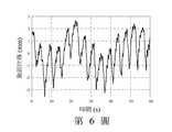
請參閱第6及7圖,第6圖為本發明之第四實施例實際對位在雷達前方30cm之一人體的胸部進行偵測而得之一位移波形,該位移波形包含了該人體不由自主的移動位移與呼吸及心跳造成的位移,第7圖則為該位移波形的頻譜分析,由圖中可以明顯看到振幅較大但頻率較低之呼吸頻率,以及振幅較小但頻率較高之心跳頻率,其中心跳頻率約為83 BPM,其與該人體同時以光體積變化描記圖法(Photoplethysmographic, PPG)量測心跳頻率而得82.4 BPM相當接近,可證明本實施例確實能夠用以偵測該人體的生命徵象。Please refer to Figures 6 and 7. Figure 6 is a displacement waveform obtained by actually detecting the chest of a human body 30cm in front of the radar according to the fourth embodiment of the present invention. The displacement waveform contains the involuntary motion of the human body. Movement displacement and the displacement caused by breathing and heartbeat. Figure 7 shows the frequency spectrum analysis of the displacement waveform. From the figure, you can clearly see the breathing frequency with larger amplitude but lower frequency, and the heartbeat with lower amplitude but higher frequency. The center beat frequency is about 83 BPM, which is quite close to the human body’s heartbeat frequency measured by Photoplethysmographic (PPG) at the same time, which proves that this embodiment can indeed be used to detect this The vital signs of the human body.
本發明之保護範圍當視後附之申請專利範圍所界定者為準,任何熟知此項技藝者,在不脫離本發明之精神和範圍內所作之任何變化與修改,均屬於本發明之保護範圍。The scope of protection of the present invention shall be determined by the scope of the attached patent application. Anyone who is familiar with the art and makes any changes and modifications without departing from the spirit and scope of the present invention shall fall within the scope of protection of the present invention. .
100:數位自我注入鎖定雷達 110:數位自我注入鎖定振盪器 111:數位諧振器 112:數位比較器 113:第一數位加法器 120:無線訊號收發單元 121:發射天線 122:接收天線 123:鏡像頻率抑制轉頻器 124:第一數位類比轉換器 125:類比數位轉換器 126:超音波發射器 127:超音波接收器 130:數位頻率解調單元 131:數位延遲器 132:數位乘法器 133:數位低通濾波器 140:第二數位類比轉換器 150:計算單元 160:數位相位調節單元 161:數位控制器 162:數位可調延遲器 163:第二數位加法器 T:目標u:數位振盪訊號uout:數位輸出訊號Sw:無線訊號Sr:反射訊號uinj:數位注入訊號w:數位解調訊號v:數位乘法訊號ud1:高頻類比偵測訊號ud2:低頻類比偵測訊號SO1:低頻類比輸出訊號SO2:高頻類比輸出訊號x:相對位移 LNA:低雜訊放大器 PA:功率放大器100: Digital Self Injection Locking Radar 110: Digital Self Injection Locking Oscillator 111: Digital Resonator 112: Digital Comparator 113: First Digital Adder 120: Wireless Signal Transceiver Unit 121: Transmitting Antenna 122: Receiving Antenna 123: Mirror Frequency Suppression converter 124: first digital-to-analog converter 125: analog-to-digital converter 126: ultrasonic transmitter 127: ultrasonic receiver 130: digital frequency demodulation unit 131: digital delayer 132: digital multiplier 133: digital Low-pass filter 140: second digital-to-analog converter 150: calculation unit 160: digital phase adjustment unit 161: digital controller 162: digital adjustable delay 163: second digital adder T: targetu : digital oscillation signaluout : digital output signalSw : wireless signalSr : reflected signaluinj : digital injection signalw : digital demodulation signalv : digital multiplication signalud1 : high frequency analog detection signalud2 : low frequency analog detection signalSO1 : Low-frequency analog output signalSO2 : High-frequency analog output signalx : Relative displacement LNA: Low noise amplifier PA: Power amplifier
第1圖:依據本發明之一實施例,一數位自我注入鎖定雷達之功能方塊圖。 第2圖:依據本發明之第一實施例,該數位自我注入鎖定雷達之電路圖。 第3圖:依據本發明之第二實施例,該數位自我注入鎖定雷達之電路圖。 第4圖:依據本發明之第三實施例,該數位自我注入鎖定雷達之電路圖。 第5圖:依據本發明之第四實施例,該數位自我注入鎖定雷達之電路圖。 第6圖:本發明之第四實施例實際進行偵測而得之一人體胸部位移的波形圖。 第7圖:本發明之第四實施例實際進行偵測而得之一人體生命徵象頻譜圖。Figure 1: A functional block diagram of a digital self-injection locking radar according to an embodiment of the present invention. Figure 2: The circuit diagram of the digital self-injection locking radar according to the first embodiment of the present invention. Figure 3: Circuit diagram of the digital self-injection locking radar according to the second embodiment of the present invention. Figure 4: The circuit diagram of the digital self-injection locking radar according to the third embodiment of the present invention. Figure 5: The circuit diagram of the digital self-injection locking radar according to the fourth embodiment of the present invention. Figure 6: A waveform diagram of a human chest displacement obtained by actual detection in the fourth embodiment of the present invention. Figure 7: The fourth embodiment of the present invention actually detects a spectrum of vital signs of the human body.
100:數位自我注入鎖定雷達100: Digital Self-Injection Locking Radar
110:數位自我注入鎖定振盪器110: Digital Self-Injection Locked Oscillator
120:無線訊號收發單元120: wireless signal transceiver unit
130:數位頻率解調單元130: Digital frequency demodulation unit
uout:數位輸出訊號uout : digital output signal
uinj:數位注入訊號uinj : digital injection signal
w:數位解調訊號w : Digital demodulation signal
Sw:無線訊號Sw : wireless signal
Sr:反射訊號Sr : reflected signal
T:目標T: target
x:相對位移x : relative displacement
Claims (9)
Translated fromChinesePriority Applications (2)
| Application Number | Priority Date | Filing Date | Title |
|---|---|---|---|
| TW109114331ATWI719893B (en) | 2020-04-29 | 2020-04-29 | Digital self-injection-locked radar |
| US17/092,920US11662453B2 (en) | 2020-04-29 | 2020-11-09 | Self-injection-locked radar with digital demodulator |
Applications Claiming Priority (1)
| Application Number | Priority Date | Filing Date | Title |
|---|---|---|---|
| TW109114331ATWI719893B (en) | 2020-04-29 | 2020-04-29 | Digital self-injection-locked radar |
Publications (2)
| Publication Number | Publication Date |
|---|---|
| TWI719893Btrue TWI719893B (en) | 2021-02-21 |
| TW202141935A TW202141935A (en) | 2021-11-01 |
Family
ID=75745968
Family Applications (1)
| Application Number | Title | Priority Date | Filing Date |
|---|---|---|---|
| TW109114331ATWI719893B (en) | 2020-04-29 | 2020-04-29 | Digital self-injection-locked radar |
Country Status (2)
| Country | Link |
|---|---|
| US (1) | US11662453B2 (en) |
| TW (1) | TWI719893B (en) |
Families Citing this family (6)
| Publication number | Priority date | Publication date | Assignee | Title |
|---|---|---|---|---|
| TWI744046B (en)* | 2020-10-22 | 2021-10-21 | 國立中山大學 | Phase-tracking self-injection-locked radar |
| FR3116613B1 (en)* | 2020-11-26 | 2023-01-20 | Commissariat Energie Atomique | RADAR DETECTION DEVICE |
| TWI756993B (en)* | 2020-12-17 | 2022-03-01 | 國立中山大學 | Vital-sign radar sensor using wireless internet signal |
| TWI780543B (en)* | 2020-12-18 | 2022-10-11 | 國立中山大學 | Frequency-converted frequency-modulated self-injection-locked radar |
| WO2023150799A1 (en)* | 2022-02-07 | 2023-08-10 | The Regents Of The University Of California | Ultra-high resolution displacement-sensing doppler radar |
| US12304427B2 (en)* | 2022-11-16 | 2025-05-20 | GM Global Technology Operations LLC | Presence-based vehicle access door release using digital key leveraging ultrasonic sensing |
Citations (5)
| Publication number | Priority date | Publication date | Assignee | Title |
|---|---|---|---|---|
| TW201143312A (en)* | 2010-05-17 | 2011-12-01 | Ind Tech Res Inst | Wireless detection apparatus and method |
| TW201830048A (en)* | 2017-02-07 | 2018-08-16 | 國立中山大學 | Quadrature self-injection-locked radar |
| US20190131982A1 (en)* | 2017-10-27 | 2019-05-02 | Mediatek Inc. | Method and associated signal system improving mitigation of injection-pulling effect |
| US20190175117A1 (en)* | 2017-12-12 | 2019-06-13 | Sil Radar Technology Inc. | Noncontact self-injection-locked sensor |
| TW202002893A (en)* | 2018-05-31 | 2020-01-16 | 國立中山大學 | Non-contact pulse transit time measurement system and non-contact vital sign sensing device thereof |
Family Cites Families (3)
| Publication number | Priority date | Publication date | Assignee | Title |
|---|---|---|---|---|
| US10411716B2 (en)* | 2016-06-06 | 2019-09-10 | Richwave Technology Corp. | Subsampling motion detector for detecting motion of object under measurement |
| US10135452B2 (en)* | 2017-02-21 | 2018-11-20 | Infineon Technologies Ag | Digital frequency synthesizer with robust injection locked divider |
| DE102018216614A1 (en)* | 2018-09-27 | 2020-04-02 | Infineon Technologies Ag | CALIBRATING AN INJECTION-SYNCHRONIZED OSCILLATOR |
- 2020
- 2020-04-29TWTW109114331Apatent/TWI719893B/enactive
- 2020-11-09USUS17/092,920patent/US11662453B2/enactiveActive
Patent Citations (5)
| Publication number | Priority date | Publication date | Assignee | Title |
|---|---|---|---|---|
| TW201143312A (en)* | 2010-05-17 | 2011-12-01 | Ind Tech Res Inst | Wireless detection apparatus and method |
| TW201830048A (en)* | 2017-02-07 | 2018-08-16 | 國立中山大學 | Quadrature self-injection-locked radar |
| US20190131982A1 (en)* | 2017-10-27 | 2019-05-02 | Mediatek Inc. | Method and associated signal system improving mitigation of injection-pulling effect |
| US20190175117A1 (en)* | 2017-12-12 | 2019-06-13 | Sil Radar Technology Inc. | Noncontact self-injection-locked sensor |
| TW202002893A (en)* | 2018-05-31 | 2020-01-16 | 國立中山大學 | Non-contact pulse transit time measurement system and non-contact vital sign sensing device thereof |
Also Published As
| Publication number | Publication date |
|---|---|
| US11662453B2 (en) | 2023-05-30 |
| TW202141935A (en) | 2021-11-01 |
| US20210341595A1 (en) | 2021-11-04 |
Similar Documents
| Publication | Publication Date | Title |
|---|---|---|
| TWI719893B (en) | Digital self-injection-locked radar | |
| US10863906B2 (en) | Range gated radio frequency physiology sensor | |
| US9375153B2 (en) | Motion/vibration sensor | |
| US8698636B2 (en) | Wireless detection apparatus and method | |
| TWI493213B (en) | Motion/interference signal detection system and method thereof | |
| TWI642406B (en) | Non-contact self-injection locking sensor | |
| TW202137711A (en) | Wireless frequency-locked-loop vital sign sensing radar | |
| CN102247146A (en) | Wireless sensing device and method | |
| US11480654B2 (en) | Radar transceiver | |
| TW202020475A (en) | Biometric detection method and biometric detection radar | |
| TWI744046B (en) | Phase-tracking self-injection-locked radar | |
| CN109239708A (en) | A kind of double frequency circuit structure for realizing vital signs detecting and short distance positioning | |
| CN111427034A (en) | Time difference range radar structure with low power consumption and simple structure | |
| CN104055519A (en) | Motion/Disturbance Detector | |
| RU2392852C2 (en) | Impulse superbroadband sensor of remote breath and heartbeat monitoring | |
| Gu et al. | Microwave and Millimeter-Wave Radars for Vital Sign Monitoring | |
| Peng et al. | Enhancement of vital-sign sensor signal-to-noise ratio using wireless frequency-locked loop | |
| TWI690720B (en) | Noncontact vibration sensor | |
| KR102632074B1 (en) | Phase demodulator with negative feedback loop | |
| Dong et al. | A millimeter-wave Doppler sensor for bio-signals detection | |
| TW202331296A (en) | Self-injection-locked monopulse radar | |
| Chen et al. | Non-contact Pulse-based Radar with an Excited RF Pulse Generator for Vital-sign Application | |
| Hakhoumian et al. | L-Band doppler radar for heartbeat sensing | |
| Li et al. | Doppler radar noncontact imaging of human cardiac motion | |
| WO2021095891A1 (en) | Microwave sensor for security monitoring |