TWI715268B - Light guide plate, backlight module and display - Google Patents
Light guide plate, backlight module and displayDownload PDFInfo
- Publication number
- TWI715268B TWI715268BTW108138788ATW108138788ATWI715268BTW I715268 BTWI715268 BTW I715268BTW 108138788 ATW108138788 ATW 108138788ATW 108138788 ATW108138788 ATW 108138788ATW I715268 BTWI715268 BTW I715268B
- Authority
- TW
- Taiwan
- Prior art keywords
- light
- guide plate
- light guide
- emitting
- total reflection
- Prior art date
Links
- 230000000694effectsEffects0.000claimsabstractdescription7
- 230000007812deficiencyEffects0.000description2
- 239000004973liquid crystal related substanceSubstances0.000description2
Images


Landscapes
- Planar Illumination Modules (AREA)
Abstract
Translated fromChineseDescription
Translated fromChinese本發明係關於一種導光板,尤指一種可對部分光源提供全反射效果,以提高發光源之光源使用率的導光板。The present invention relates to a light guide plate, in particular to a light guide plate that can provide a total reflection effect to part of the light source to improve the utilization rate of the light source of the light source.
現有液晶顯示器的背光模組主要包含有一導光板及一設置於導光板之一入光面的發光源,該發光源具有多數個可為發光二極體(LED)之發光體,如此藉由導光板可將發光源之發光體所發出的光線均勻地散布於整個導光板,來提供液晶面板一顯示畫面的背光光源。The backlight module of the existing liquid crystal display mainly includes a light guide plate and a light emitting source arranged on a light incident surface of the light guide plate. The light emitting source has a plurality of light emitting bodies that can be light emitting diodes (LEDs). The light plate can evenly spread the light emitted by the luminous body of the light source on the entire light guide plate to provide a backlight light source for the liquid crystal panel to display images.
然而,因各發光體在發光時,其光源係呈輻射狀向外發出,因此有部分光源將不會進入導光板中,尤其是部份較大功率的LED,為避免LED發光時所產生的熱量影響到導光板,甚至令導光板有熔化的現象,發光體與導光板間會形成有一間距,如此將令發光體進入導光板的能量降低,而影響了整個背光模組的發光效率。However, because each luminous body emits light in a radial shape when emitting light, some light sources will not enter the light guide plate, especially some high-power LEDs, in order to avoid the occurrence of LED lighting. The heat affects the light guide plate, and even causes the light guide plate to melt. There will be a gap between the luminous body and the light guide plate. This will reduce the energy of the luminous body entering the light guide plate and affect the luminous efficiency of the entire backlight module.
因此,本發明人有鑑於現有導光板結構及使用上的不足與缺失,特經過不斷的試驗與研究,終於發展出一種可改進現有缺失之本發明。Therefore, in view of the shortcomings and deficiencies in the structure and use of the existing light guide plate, the inventors have finally developed an invention that can improve the existing deficiencies after continuous experiments and research.
本發明之主要目的,在於提供一種導光板,其於導光板的入光面形成有具全反射效果的全反射面,如此可使部份發光體的光源經全反射面反射進入導光板中,來避免發光體能量的流失,以達到提高發光源能量的使用效率之目的。The main purpose of the present invention is to provide a light guide plate, which has a total reflection surface with total reflection effect formed on the light incident surface of the light guide plate, so that part of the light source of the luminous body can be reflected into the light guide plate through the total reflection surface. To avoid the energy loss of the luminous body, so as to achieve the purpose of improving the efficiency of the use of the luminous source energy.
為達上述目的,本發明係提供一種導光板,用以與一發光源配合而將該發光源所射出的光線轉化為平面光源,該導光板包含有:一本體,該本體的一側面係定義為一入光面,該本體的一頂面係定義為一出光面;以及一反射部,該反射部上形成有一具全反射效果的全反射面,該全反射面連接該入光面與該出光面;其中,於該本體的厚度方向上,該本體的厚度大於該發光源的高度;其中,該本體與該發光源具有一間隙,且該反射部圍繞於該間隙之一側。To achieve the above object, the present invention provides a light guide plate for cooperating with a light source to convert the light emitted by the light source into a planar light source. The light guide plate includes: a body, and a side surface of the body defines Is a light-incident surface, a top surface of the main body is defined as a light-emitting surface; and a reflection portion, the reflection portion is formed with a total reflection surface with a total reflection effect, the total reflection surface connects the light-incident surface and the Light-emitting surface; wherein, in the thickness direction of the body, the thickness of the body is greater than the height of the light-emitting source; wherein the body and the light-emitting source have a gap, and the reflective portion surrounds one side of the gap.
藉由上述技術手段,本發明可藉由反射部上的全反射面將部份原本會由本體與發光體間之間隙散失的光源,反射而進入本體內再利用,而可藉此減少發光源能量的損失,進而能提高整體的發光效率。With the above technical means, the present invention can reflect part of the light source that would otherwise be lost through the gap between the main body and the light-emitting body through the total reflection surface on the reflector and enter the main body for reuse, thereby reducing light-emitting sources. The loss of energy can increase the overall luminous efficiency.
10,10A:本體10, 10A: body
12,12A:入光面12, 12A: Light incident surface
14:出光面14: Glossy surface
20:反射部20: reflection part
22,22A:全反射面22, 22A: Total reflection surface
30:發光體30: luminous body
40:顯示面板40: display panel
L1:第一中心線L1: the first center line
L2:第二中心線L2: second center line
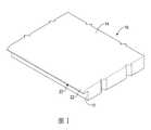
圖1係本發明第一實施例之局部立體外觀圖。Fig. 1 is a partial perspective view of the first embodiment of the present invention.
圖2係本發明構成背光模組之立體外觀圖。2 is a perspective view of the backlight module of the present invention.
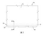
圖3係本發明第一實施例之局部上視圖。Figure 3 is a partial top view of the first embodiment of the present invention.
圖4係本發明第一實施例沿圖2A-A線之使用剖面示意圖。Fig. 4 is a schematic cross-sectional view taken along the line of Fig. 2A-A of the first embodiment of the present invention.
圖5係本發明構成顯示器之側視示意圖。Fig. 5 is a schematic side view of the display of the present invention.
圖6係本發明第二實施例之局部立體外觀放大圖。Fig. 6 is a partial three-dimensional external enlarged view of the second embodiment of the present invention.
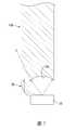
圖7係本發明第三實施例之側視剖面圖。Fig. 7 is a side sectional view of the third embodiment of the present invention.
本發明係提供一種導光板、背光模組及顯示器,請配合參看圖1至圖3,其中本發明的導光板係用以與一發光源配合而將該發光源所射出的光線轉化為平面光源,並共同組成一背光模組,該發光源具有多數個發光體30,該導光板包含有一本體10及一反射部20,該本體10的一側面係定義為一入光面12,該本體10的一頂面係定義為一出光面14,該反射部20上形成有一具全反射效果的全反射面22,該全反射面22連接該入光面12與該出光面14,其中於該本體10的厚度方向上,該本體10的厚度大於該發光源的高度,又反射部20可如圖所示的呈單一條狀凸設於本體10上,亦或該反射部20可呈分多段形式凸設於本體10上,且分別對應發光源的發光體30,又如圖5所示,於導光板的出光面14之一側設置一顯示面板40,即構成一顯示器。The present invention provides a light guide plate, a backlight module and a display. Please refer to FIGS. 1 to 3 together. The light guide plate of the present invention is used with a light source to convert the light emitted by the light source into a flat light source , And together form a backlight module, the light-emitting source has a plurality of light-emitting
另外,該全反射面22係為一具有曲率的面,較佳地,該全反射面22係為一具有變動曲率的面,藉此可以精確地控制每個位置的曲率,使得各個位置的光線都能達到全反射的效果,確保光線皆能反射而進入到本體10內,其次,如圖6所示,該全反射面22A可由多數個連續的小平面所構成,如此可提高本體10模具開設時的方便性,進而能降低整體的生產成本,又本體10的厚度方向上,該本體10具有一第一中心線L1,每一發光體具有一第二中心線L2,該第一中心線L1相較於第二中心線L2更靠近該全反射面22,藉此,發光體30的位置會低於本體10的中央位置,所以反射部20距離發光體30較遠,可以涵蓋發光體30的發光角度,讓發光體30發出的光線可以有效被反射部所反射而進入到該本體10。In addition, the
藉此,請配合參看圖4,當發光源的發光體30發出光線後,部份的光線會由入光面12進入導光板的本體10內,並經導光板的傳導使光線均勻散布於整個本體10上,而由於該本體10的厚度大於該發光源的高度,所以該發光源是被該本體10所涵蓋,該發光源所發射的光線皆可以進入到該本體10,但仍因為該本體10與該發光源具有間隙,且該反射部20圍繞於該間隙之一側,所以部份原本會由本體10與發光體30間之間隙散失的光源,會進入反射部20內,並經反射部20的全反射面22反射而進入本體10內再利用,如此可減少發光源能量的損失,而能提高整體的發光效率。Therefore, please refer to FIG. 4. When the
又請配合參看圖7,圖中所示本發明的第二實施例中,於導光板本體10的入光面12A係設置為一凹弧面,藉此,當發光體30所發出光線進入導光板的本體10A內時,可透過呈凹弧面的入光面12A使光線的折射角度較如圖1第一實施例之平面入光面12的折射角度更大,使發光體30在上下或左右方向上進入本體10A的出射光能更加地開張,能更均勻地分佈於整個本體10上。Please also refer to FIG. 7 in which in the second embodiment of the present invention shown in the figure, the
藉由導光板本體10的入光面12A為凹弧面的設置,可提高發光體30所發出光線進入導光板本體10A內的入光角,以改善導光板出現暗帶及亮度不均的問題,而能提昇背光模組整體的發光效率。By setting the
10:本體10: body
12:入光面12: Glossy surface
14:出光面14: Glossy surface
20:反射部20: reflection part
22:全反射面22: Total reflection surface
Claims (9)
Translated fromChinesePriority Applications (1)
| Application Number | Priority Date | Filing Date | Title |
|---|---|---|---|
| TW108138788ATWI715268B (en) | 2019-10-28 | 2019-10-28 | Light guide plate, backlight module and display |
Applications Claiming Priority (1)
| Application Number | Priority Date | Filing Date | Title |
|---|---|---|---|
| TW108138788ATWI715268B (en) | 2019-10-28 | 2019-10-28 | Light guide plate, backlight module and display |
Publications (2)
| Publication Number | Publication Date |
|---|---|
| TWI715268Btrue TWI715268B (en) | 2021-01-01 |
| TW202117415A TW202117415A (en) | 2021-05-01 |
Family
ID=75237644
Family Applications (1)
| Application Number | Title | Priority Date | Filing Date |
|---|---|---|---|
| TW108138788ATWI715268B (en) | 2019-10-28 | 2019-10-28 | Light guide plate, backlight module and display |
Country Status (1)
| Country | Link |
|---|---|
| TW (1) | TWI715268B (en) |
Citations (5)
| Publication number | Priority date | Publication date | Assignee | Title |
|---|---|---|---|---|
| TW200938889A (en)* | 2008-03-11 | 2009-09-16 | Nano Prec Corp | Light guide device and backlight module |
| TWM466276U (en)* | 2013-03-07 | 2013-11-21 | Four Sun Tech Inc | Light guide structure |
| TW201426040A (en)* | 2012-12-27 | 2014-07-01 | Au Optronics Corp | Light guide plate and backlight module |
| TW201719209A (en)* | 2015-08-14 | 2017-06-01 | 瑞儀光電(蘇州)有限公司 | Light guide film, backlight module and display device |
| TWM558919U (en)* | 2017-08-17 | 2018-04-21 | Radiant Opto Electronics Suzhou Co Ltd | Light guide plate, backlight module and display device |
- 2019
- 2019-10-28TWTW108138788Apatent/TWI715268B/enactive
Patent Citations (5)
| Publication number | Priority date | Publication date | Assignee | Title |
|---|---|---|---|---|
| TW200938889A (en)* | 2008-03-11 | 2009-09-16 | Nano Prec Corp | Light guide device and backlight module |
| TW201426040A (en)* | 2012-12-27 | 2014-07-01 | Au Optronics Corp | Light guide plate and backlight module |
| TWM466276U (en)* | 2013-03-07 | 2013-11-21 | Four Sun Tech Inc | Light guide structure |
| TW201719209A (en)* | 2015-08-14 | 2017-06-01 | 瑞儀光電(蘇州)有限公司 | Light guide film, backlight module and display device |
| TWM558919U (en)* | 2017-08-17 | 2018-04-21 | Radiant Opto Electronics Suzhou Co Ltd | Light guide plate, backlight module and display device |
Also Published As
| Publication number | Publication date |
|---|---|
| TW202117415A (en) | 2021-05-01 |
Similar Documents
| Publication | Publication Date | Title |
|---|---|---|
| TWI471504B (en) | Flat light source module | |
| CN100419522C (en) | Light guide plate and backlight system | |
| JP2015103323A (en) | Lighting device | |
| TW201300894A (en) | Edge lighting backlight module | |
| CN216113547U (en) | Backlight structure | |
| TW201441687A (en) | Light guide device and backlight module with same | |
| WO2018201538A1 (en) | Led light strip and backlight assembly | |
| CN207350164U (en) | Light distribution structure, automobile signal light and automobile for automobile signal light | |
| TWI503581B (en) | Lens, light source device and direct type light source module | |
| KR20150137959A (en) | Secondary optical element and light source module | |
| TW201326977A (en) | Lighting emitting apparatus and manufacturing method thereof | |
| TWI715268B (en) | Light guide plate, backlight module and display | |
| TW201405059A (en) | Light source module | |
| CN106764787A (en) | A kind of LED disc types lens optical system | |
| JP2012173661A (en) | Lens for illuminating device and illuminating device | |
| JP5575627B2 (en) | Light bulb type LED lamp | |
| CN210776108U (en) | Lens for television backlight module | |
| TW201502582A (en) | Lens and ligth source module using the same | |
| TW201539047A (en) | Lens and direct type light source module | |
| CN107678084A (en) | A large-area light guide plate | |
| CN103175032B (en) | Backlight source and display device | |
| CN207762826U (en) | Multi-panel reflective lens | |
| CN100426074C (en) | Back light module | |
| CN207555471U (en) | Lamp lens | |
| TWI437291B (en) | Light guide plate and backlight module using the same |