Movatterモバイル変換


[0]ホーム

URL:


TWI714938B - Control method and electronic system - Google Patents

Control method and electronic system
Download PDF

Info

Publication number
TWI714938B
TWI714938BTW108100312ATW108100312ATWI714938BTW I714938 BTWI714938 BTW I714938BTW 108100312 ATW108100312 ATW 108100312ATW 108100312 ATW108100312 ATW 108100312ATW I714938 BTWI714938 BTW I714938B
Authority
TW
Taiwan
Prior art keywords
pin
channel configuration
peripheral device
host device
transmission path
Prior art date
Application number
TW108100312A
Other languages
Chinese (zh)
Other versions
TW202026898A (en
Inventor
蔡志勇
Original Assignee
宏碁股份有限公司
Priority date (The priority date is an assumption and is not a legal conclusion. Google has not performed a legal analysis and makes no representation as to the accuracy of the date listed.)
Filing date
Publication date
Application filed by 宏碁股份有限公司filedCritical宏碁股份有限公司
Priority to TW108100312ApriorityCriticalpatent/TWI714938B/en
Publication of TW202026898ApublicationCriticalpatent/TW202026898A/en
Application grantedgrantedCritical
Publication of TWI714938BpublicationCriticalpatent/TWI714938B/en

Links

Images

Landscapes

Abstract

A control method for an electronic system is provided. The electronic system includes a host device, a cable and a peripheral device. The control method includes connecting the cable to the host device and peripheral device, detecting a pull-up resistor of the host device by the peripheral device, detecting a pull-down resistor of the peripheral device by the host device, the host device implementing a first data communication with the peripheral device through the cable for determining a transmission mode according to a first communication protocol, and the host device selectively using a first transmission path or a second transmission path and implementing a second data communication with the peripheral device according to a second communication protocol corresponding to the transmission mode, so as to transmit signal to the peripheral device through the first transmission path or the second transmission path.

Description

Translated fromChinese
控制方法及電子系統Control method and electronic system

本發明係指一種控制方法及電子系統,尤指一種可應用於USB Type-C傳輸之控制方法及電子系統。The present invention refers to a control method and electronic system, especially a control method and electronic system applicable to USB Type-C transmission.

隨著電腦及周邊設備產業的發展,通用序列匯流排(Universal Serial Bus,USB)已成為電腦與周邊設備的溝通及資料傳輸的重要傳輸介面之一。由於通用序列匯流排介面具有可插拔及容易安裝等特性,其已逐漸取代了各種傳統的外接介面,並且廣泛用於各種外接設備的連結,如滑鼠、鍵盤、智慧型行動通訊裝置、筆記型電腦、外接式硬碟、隨身碟等。With the development of the computer and peripheral equipment industry, the Universal Serial Bus (USB) has become one of the important transmission interfaces for communication and data transmission between computers and peripheral equipment. Because the universal serial bus interface is pluggable and easy to install, it has gradually replaced various traditional external interfaces and is widely used in connection with various external devices, such as mice, keyboards, smart mobile communication devices, and notebooks. Type computers, external hard drives, flash drives, etc.

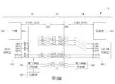
請參考第1圖以及第2圖,第1圖以及第2圖為傳統應用USB Type-C傳輸之一電子系統1之運作示意圖。如第1圖所示,電子系統1包含有一主機端裝置10、一電纜12以及一週邊裝置14。主機端裝置10經由電纜12連接至週邊裝置14。主機端裝置10包含有一主機102、一視訊源裝置104、一電力傳輸(Power Delivery,PD)控制器106、一多工器108以及一連接器110。週邊裝置14包含有一從裝置142、一視訊接收裝置144、一電力傳輸控制器146、一多工器148以及一連接器150。如第1圖所示,當電力傳輸控制器106經由通道組態接腳CC1偵測出主機端裝置10之一上拉電阻時,這表示週邊裝置14之連接器148與電纜12為正插連接。週邊裝置14之多工器108將多工器108之接腳I1、I2分別連接至多工器108之接腳O1、O2並將多工器108之接腳I3、I4分別連接至多工器108之接腳O3、O4。如第2圖所示,當電力傳輸控制器106經由通道組態接腳CC2偵測出主機端裝置10之一上拉電阻時,這表示週邊裝置14之連接器148與電纜12為反插連接。週邊裝置14之多工器108將多工器108之接腳I1、I2分別連接至多工器108之接腳O3、O4並將多工器108之接腳I3、I4分別連接至多工器108之接腳O1、O2。簡言之,週邊裝置14之多工器108可依據連接器148與電纜12之連接關係來做相應的切換連接,以維持訊號的正常傳輸。Please refer to Figure 1 and Figure 2. Figure 1 and Figure 2 are schematic diagrams of the operation of anelectronic system 1 that uses USB Type-C transmission in a traditional way. As shown in FIG. 1, theelectronic system 1 includes ahost device 10, acable 12, and aperipheral device 14. Thehost device 10 is connected to theperipheral device 14 via acable 12.Thehost device 10 includes ahost 102, avideo source device 104, a power delivery (PD)controller 106, amultiplexer 108, and aconnector 110. Theperipheral device 14 includes a slave device 142, avideo receiving device 144, apower transmission controller 146, a multiplexer 148 and aconnector 150. As shown in Figure 1, when thepower transmission controller 106 detects a pull-up resistor of thehost device 10 via the channel configuration pin CC1, it means that the connector 148 of theperipheral device 14 and thecable 12 are positively connected . Themultiplexer 108 of theperipheral device 14 connects the pins I1 and I2 of themultiplexer 108 to the pins O1 and O2 of themultiplexer 108 respectively, and connects the pins I3 and I4 of themultiplexer 108 to themultiplexer 108 respectively. Pins O3, O4.As shown in Figure 2, when thepower transmission controller 106 detects a pull-up resistor of thehost device 10 via the channel configuration pin CC2, it means that the connector 148 of theperipheral device 14 and thecable 12 are reversely connected . Themultiplexer 108 of theperipheral device 14 connects the pins I1 and I2 of themultiplexer 108 to the pins O3 and O4 of themultiplexer 108 respectively, and connects the pins I3 and I4 of themultiplexer 108 to themultiplexer 108 respectively Pins O1 and O2. In short, themultiplexer 108 of theperipheral device 14 can make corresponding switching connections according to the connection relationship between the connector 148 and thecable 12 to maintain the normal signal transmission.

因此,本發明之主要目的即在於提供一種控制方法及電子系統,以應用於USB Type-C資料傳輸,使得週邊裝置不需外接額外的電路元件,即實現傳輸目的。Therefore, the main purpose of the present invention is to provide a control method and an electronic system for USB Type-C data transmission, so that peripheral devices do not need to be connected with additional circuit components, that is, to achieve the purpose of transmission.

本發明提供一種控制方法,用於一電子系統,該電子系統包含有一主機端裝置、一電纜以及一週邊裝置,該主機端裝置包含有一第一通道組態接腳以及一第二通道組態接腳,該電纜包含有一通道組態接腳,該週邊裝置包含有一第三通道組態接腳以及一第四通道組態接腳,該控制方法包含有:將該電纜之一通道組態接腳連接至該主機端裝置之一第一通道組態接腳以及將該電纜之該通道組態接腳連接至該週邊裝置之一第三通道組態接腳與一第四通道組態接腳之其中之一;經由該主機端裝置之該第一通道組態接腳偵測出該週邊裝置之一下拉電阻;經由該週邊裝置之該第三通道組態接腳與一第四通道組態接腳之其中之一偵測出該主機端裝置之一上拉電阻;該主機端裝置根據一第一通訊協定經由該電纜之該通道組態接腳與該週邊裝置進行一第一資料通訊以決定一傳輸模式;以及該主機端裝置選擇性地使用一第一傳輸路徑或一第二傳輸路徑,並根據相應於該傳輸模式之一第二通訊協定來與該週邊裝置進行一第二資料通訊,以經由該第一傳輸路徑或該第二傳輸路徑傳送訊號至該週邊裝置。The present invention provides a control method for an electronic system. The electronic system includes a host device, a cable, and a peripheral device. The host device includes a first channel configuration pin and a second channel configuration connector. The cable includes a channel configuration pin, the peripheral device includes a third channel configuration pin and a fourth channel configuration pin, the control method includes: one of the cable channel configuration pins Connect to a first channel configuration pin of the host device and connect the channel configuration pin of the cable to one of a third channel configuration pin and a fourth channel configuration pin of the peripheral device One of them; a pull-down resistor of the peripheral device is detected through the first channel configuration pin of the host device; the third channel configuration pin of the peripheral device is connected to a fourth channel configuration pin One of the pins detects a pull-up resistor of the host device; the host device performs a first data communication with the peripheral device through the channel configuration pin of the cable according to a first communication protocol to determine A transmission mode; and the host device selectively uses a first transmission path or a second transmission path, and performs a second communication with the peripheral device according to a second communication protocol corresponding to the transmission modeData communication to transmit signals to the peripheral device via the first transmission path or the second transmission path.

本發明提供一種電子系統,包含:一主機端裝置,包含有一第一通道組態接腳以及一第二通道組態接腳;一電纜,耦接於該主機端裝置,該電纜包含有一通道組態接腳,該電纜之該通道組態接腳連接至該主機端裝置之該第一通道組態接腳;以及一週邊裝置,耦接於該電纜,該週邊裝置包含有一第三通道組態接腳以及一第四通道組態接腳,該週邊裝置之該第三通道組態接腳與該第四通道組態接腳之其中之一連接至該電纜之該通道組態接腳;其中,該主機端裝置經由該第一通道組態接腳偵測出該週邊裝置之一下拉電阻,該週邊裝置經由該第三通道組態接腳與該第四通道組態接腳之其中之一偵測出該主機端裝置之一上拉電阻,該主機端裝置根據一第一通訊協定經由該電纜之該通道組態接腳與該週邊裝置進行一第一資料通訊以決定一傳輸模式,以及該主機端裝置選擇性地使用一第一傳輸路徑或一第二傳輸路徑並根據相應於該傳輸模式之一第二通訊協定來與該週邊裝置進行一第二資料通訊,以經由該第一傳輸路徑或該第二傳輸路徑傳送訊號至該週邊裝置。The present invention provides an electronic system, including: a host device including a first channel configuration pin and a second channel configuration pin; a cable coupled to the host device, the cable including a channel group Status pin, the channel configuration pin of the cable is connected to the first channel configuration pin of the host device; and a peripheral device coupled to the cable, the peripheral device includes a third channel configuration Pin and a fourth channel configuration pin, one of the third channel configuration pin and the fourth channel configuration pin of the peripheral device is connected to the channel configuration pin of the cable; wherein , The host device detects a pull-down resistor of the peripheral device through the first channel configuration pin, and the peripheral device through one of the third channel configuration pin and the fourth channel configuration pin A pull-up resistor of the host device is detected, the host device performs a first data communication with the peripheral device via the channel configuration pin of the cable according to a first communication protocol to determine a transmission mode, and The host device selectively uses a first transmission path or a second transmission path, and performs a second data communication with the peripheral device according to a second communication protocol corresponding to the transmission mode, so as to pass the first transmission The path or the second transmission path transmits the signal to the peripheral device.

1、3:電子系統1, 3: Electronic system

10、30:主機端裝置10.30: Host device

102、302:主機102, 302: host

104、304:視訊源裝置104, 304: Video source device

106、146、306、346:電力傳輸控制器106, 146, 306, 346: power transmission controller

108、148、308:多工器108, 148, 308: multiplexer

110、150、312、348:連接器110, 150, 312, 348: connector

12、32:電纜12, 32: Cable

14:週邊裝置14: Peripheral devices

142:從裝置142: Slave Device

144:視訊接收裝置144: Video receiving device

310:驅動器310: drive

4:流程4: process

AUXp、AUXn、RX1~RX2、SBU1~SBU2、TX1~TX2、USB2_D+/D-:接腳AUXp, AUXn, RX1~RX2, SBU1~SBU2, TX1~TX2, USB2_D+/D-: pin

CC、CC1~CC2:通道組態接腳CC, CC1~CC2: channel configuration pins

DP0~DP3:視訊接腳DP0~DP3: video pins

I1~I6:輸入接腳I1~I6: Input pins

O1~O6:輸出接腳O1~O6: output pins

S400、S402、S404、S406、S408、S410、S400, S402, S404, S406, S408, S410,

S412:步驟S412: Step

第1圖以及第2圖分別為傳統應用USB Type-C傳輸之電子系統之運作示意圖。Figure 1 and Figure 2 are schematic diagrams of the operation of traditional electronic systems using USB Type-C transmission.

第3圖為本發明實施例之一電子系統之示意圖。Figure 3 is a schematic diagram of an electronic system according to an embodiment of the invention.

第4圖為本發明實施例之一流程之示意圖Figure 4 is a schematic diagram of a process of an embodiment of the present invention

第5圖以及第6圖分別為本發明實施例之電子系統之運作示意圖。Figures 5 and 6 are respectively schematic diagrams of the operation of the electronic system according to the embodiment of the present invention.

在說明書及後續的申請專利範圍當中使用了某些詞彙來指稱特定的元件。所屬技術領域中具有通常知識者應可理解,製造商可能會用不同的名詞來稱呼同樣的元件。本說明書及後續的申請專利範圍並不以名稱的差異來做為區分元件的方式,而是以元件在功能上的差異來做為區分的基準。在通篇說明書及後續的申請專利範圍當中所提及的「包含」或「包括」係為一開放式的用語,故應解釋成「包括但不限定於」。另外,「耦接」一詞在此係包含任何直接及間接的電氣連接手段。因此,若文中描述一第一裝置耦接於一第二裝置,則代表該第一裝置可直接電氣連接於該第二裝置,或透過其他裝置或連接手段間接地電氣連接至該第二裝置。In the specification and subsequent patent applications, certain words are used to refer to specificelement. Those with ordinary knowledge in the technical field should understand that manufacturers may use different terms to refer to the same components. The scope of this specification and subsequent patent applications does not use differences in names as a way of distinguishing elements, but uses differences in functions as a basis for distinction. The "include" or "include" mentioned in the entire specification and subsequent patent applications are open-ended terms and should be interpreted as "including but not limited to". In addition, the term "coupling" here includes any direct and indirect electrical connection means. Therefore, if it is described that a first device is coupled to a second device, it means that the first device can be directly electrically connected to the second device, or indirectly electrically connected to the second device through other devices or connection means.

請參考第3圖,第3圖為本發明實施例之一電子系統3之示意圖。電子系統3可應用於USB Type-C之訊號傳輸。電子系統1包含有一主機端裝置30、一電纜32以及一週邊裝置34。主機端裝置30經由電纜32連接至週邊裝置34。主機端裝置30包含有一主機302、一視訊源裝置304、一電力傳輸控制器306、一多工器308、一驅動器310以及一連接器312。週邊裝置34包含有一從裝置342、一視訊接收裝置344、一電力傳輸控制器346以及一連接器348。主機302包含有接腳USB2_D+/D-。視訊源裝置304包含有視訊接腳DP0~DP3以及接腳AUXp、AUXn。電力傳輸控制器306包含有通道組態接腳CC1~CC2。多工器308包含有輸入接腳I1~I6以及輸出接腳O1~O6。連接器312包含有通道組態接腳CC1~CC2、接腳USB2_D+/D-、TX1~TX2、RX1~RX2、SBU1~SBU2。從裝置342包含有接腳USB2_D+/D-。視訊接收裝置344包含有視訊接腳DP0~DP3以及接腳AUXp、AUXn。連接器348包含有通道組態接腳CC1~CC2、接腳USB2_D+/D-、TX1~TX2、RX1~RX2、SBU1~SBU2。電力傳輸控制器346包含有通道組態接腳CC1~CC2。Please refer to FIG. 3, which is a schematic diagram of anelectronic system 3 according to an embodiment of the present invention. Theelectronic system 3 can be applied to USB Type-C signal transmission. Theelectronic system 1 includes ahost device 30, acable 32 and aperipheral device 34. Thehost device 30 is connected to theperipheral device 34 via acable 32. Thehost device 30 includes ahost 302, avideo source device 304, apower transmission controller 306, a multiplexer 308, adriver 310, and aconnector 312. Theperipheral device 34 includes aslave device 342, avideo receiving device 344, apower transmission controller 346, and aconnector 348. Thehost 302 includes pins USB2_D+/D-. Thevideo source device 304 includes video pins DP0 to DP3 and pins AUXp and AUXn. Thepower transmission controller 306 includes channel configuration pins CC1~CC2. The multiplexer 308 includes input pins I1~I6 and output pins O1~O6. Theconnector 312 includes channel configuration pins CC1~CC2, pins USB2_D+/D-, TX1~TX2, RX1~RX2, SBU1~SBU2. Theslave device 342 includes pins USB2_D+/D-. Thevideo receiving device 344 includes video pins DP0 to DP3 and pins AUXp and AUXn. Theconnector 348 includes channel configuration pins CC1~CC2, pins USB2_D+/D-, TX1~TX2, RX1~RX2, SBU1~SBU2. Thepower transmission controller 346 includes channel configuration pins CC1~CC2.

如第3圖所示,視訊源裝置304之視訊接腳DP0~DP3分別耦接於多工器308之輸入接腳I1~I4。多工器308之輸出接腳O1~O4分別耦接於連接器312之接腳TX1、RX1、TX2、RX2。視訊接收裝置344之視訊接腳DP0~DP3分別耦接於連接器312之接腳RX1、TX1、RX2、TX2。當連接器312與電纜32連接時,電纜32之通道組態接腳CC耦接於連接器312之通道組態接腳CC1或通道組態接腳CC2。當連接器348與電纜32連接時,電纜32之通道組態接腳CC耦接於連接器348之通道組態接腳CC1或通道組態接腳CC2。主機端裝置30之電力傳輸控制器306可以透過配置通道接腳CC1、CC2與週邊裝置34之電力傳輸控制器346耦接以進行溝通。As shown in FIG. 3, the video pins DP0~DP3 of thevideo source device 304 are respectively coupled to the input pins I1~I4 of the multiplexer 308. The output pins O1 to O4 of the multiplexer 308 are respectively coupled to the pins TX1, RX1, TX2, and RX2 of theconnector 312. The video pins DP0 to DP3 of thevideo receiving device 344 are respectively coupled to the pins RX1, TX1, RX2, and TX2 of theconnector 312. When theconnector 312 is connected to thecable 32, the channel configuration pin CC of thecable 32 is coupled to the channel configuration pin CC1 or the channel configuration pin CC2 of theconnector 312. When theconnector 348 is connected to thecable 32, the channel configuration pin CC of thecable 32 is coupled to the channel configuration pin CC1 or the channel configuration pin CC2 of theconnector 348. Thepower transmission controller 306 of thehost device 30 can be coupled to thepower transmission controller 346 of theperipheral device 34 for communication through configuration channel pins CC1 and CC2.

當主機端裝置30經由電纜32連接至週邊裝置34時,主機端裝置30可選擇性地使用一第一傳輸路徑或一第二傳輸路徑並經由第一傳輸路徑或第二傳輸路徑傳送訊號至該週邊裝置。其中,第一傳輸路徑包含由視訊源裝置304之視訊接腳DP0、多工器308之輸入接腳I1、多工器308之輸出接腳O1以及連接器312之接腳TX1所形成之一傳輸路徑、由視訊源裝置304之視訊接腳DP1、多工器308之輸入接腳I2、多工器308之輸出接腳O21以及連接器312之接腳RX1所形成之一傳輸路徑、由視訊源裝置304之視訊接腳DP2、多工器308之輸入接腳I3、多工器308之輸出接腳O31以及連接器312之接腳TX2所形成之一傳輸路徑以及由視訊源裝置304之視訊接腳DP3、多工器308之輸入接腳I4、多工器308之輸出接腳O41以及連接器312之接腳RX2所形成之一傳輸路徑。第二傳輸路徑包含由視訊源裝置304之視訊接腳DP0、多工器308之輸入接腳I1、多工器308之輸出接腳O3以及連接器312之接腳TX2所形成之一傳輸路徑、由視訊源裝置304之視訊接腳DP1、多工器308之輸入接腳I2、多工器308之輸出接腳O4以及連接器312之接腳RX2所形成之一傳輸路徑、由視訊源裝置304之視訊接腳DP2、多工器308之輸入接腳I3、多工器308之輸出接腳O1以及連接器312之接腳TX1所形成之一傳輸路徑以及由視訊源裝置304之視訊接腳DP3、多工器308之輸入接腳I4、多工器308之輸出接腳O2以及連接器312之接腳RX1所形成之一傳輸路徑。When thehost device 30 is connected to theperipheral device 34 via thecable 32, thehost device 30 can selectively use a first transmission path or a second transmission path and transmit signals to the first transmission path or the second transmission path. Peripheral devices. Wherein, the first transmission path includes one transmission formed by the video pin DP0 of thevideo source device 304, the input pin I1 of the multiplexer 308, the output pin O1 of the multiplexer 308, and the pin TX1 of theconnector 312. Path, a transmission path formed by the video pin DP1 of thevideo source device 304, the input pin I2 of the multiplexer 308, the output pin O21 of the multiplexer 308, and the pin RX1 of theconnector 312, and the video source A transmission path formed by the video pin DP2 of thedevice 304, the input pin I3 of the multiplexer 308, the output pin O31 of the multiplexer 308, and the pin TX2 of theconnector 312, and the video connection of thevideo source device 304 The pin DP3, the input pin I4 of the multiplexer 308, the output pin O41 of the multiplexer 308, and the pin RX2 of theconnector 312 form a transmission path. The second transmission path includes a transmission path formed by the video pin DP0 of thevideo source device 304, the input pin I1 of the multiplexer 308, the output pin O3 of the multiplexer 308, and the pin TX2 of theconnector 312, It is determined by the video pin DP1 of thevideo source device 304, the input pin I2 of the multiplexer 308, the output pin O4 of the multiplexer 308, and the pin RX2 of the connector 312A transmission path is formed by the video pin DP2 of thevideo source device 304, the input pin I3 of the multiplexer 308, the output pin O1 of the multiplexer 308, and the pin TX1 of theconnector 312. And a transmission path is formed by the video pin DP3 of thevideo source device 304, the input pin I4 of the multiplexer 308, the output pin O2 of the multiplexer 308, and the pin RX1 of theconnector 312.

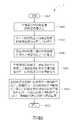
關於電子系統3的運作說明,請參考第4圖。第4圖為本發明實施例之一流程4之示意圖。第4圖所示流程主要是對應於第3圖之電子系統3的操作。流程4包含以下步驟:步驟S400:開始。For the operation description ofelectronic system 3, please refer to Figure 4. Figure 4 is a schematic diagram of aprocess 4 of an embodiment of the present invention. The flow shown in Fig. 4 mainly corresponds to the operation of theelectronic system 3 in Fig. 3. Theprocess 4 includes the following steps: Step S400: Start.

步驟S402:主機端裝置30經由電纜32耦接至週邊裝置34。Step S402: thehost device 30 is coupled to theperipheral device 34 via thecable 32.

步驟S404:經由主機端裝置30之通道組態接腳CC1偵測出週邊裝置34之下拉電阻。Step S404: Detect the pull-down resistance of theperipheral device 34 through the channel configuration pin CC1 of thehost device 30.

步驟S406:經由週邊裝置34之通道組態接腳CC1或通道組態接腳通道組態接腳CC2偵測出主機端裝置30之上拉電阻。Step S406: Detect the pull-up resistor of thehost device 30 via the channel configuration pin CC1 or the channel configuration pin CC2 of theperipheral device 34.

步驟S408:主機端裝置30根據第一通訊協定經由電纜32之通道組態接腳CC來與週邊裝置34進行第一資料通訊以決定傳輸模式。Step S408: Thehost device 30 performs first data communication with theperipheral device 34 via the channel configuration pin CC of thecable 32 according to the first communication protocol to determine the transmission mode.

步驟S410:主機端裝置30選擇性地使用第一傳輸路徑或第二傳輸路徑,並根據相應於傳輸模式之第二通訊協定來與週邊裝置34進行第二資料通訊,以經由該第一傳輸路徑或該第二傳輸路徑傳送訊號至週邊裝置34。Step S410: Thehost device 30 selectively uses the first transmission path or the second transmission path, and performs second data communication with theperipheral device 34 according to the second communication protocol corresponding to the transmission mode, so as to pass through the first transmission path Or the second transmission path transmits the signal to theperipheral device 34.

步驟S412:結束。Step S412: End.

根據流程4,於步驟S402中,於電子系統3運作時,主機端裝置30經由電纜32連接至週邊裝置34,也就是說,電纜之一端耦接於主機端裝置30之連接器312,電纜之另一端耦接於週邊裝置34之連接器348。如此一來,電纜32之通道組態接腳CC會耦接於連接器312之通道組態接腳CC1或通道組態接腳CC2。電纜32之通道組態接腳CC亦會耦接於連接器348之通道組態接腳CC1或通道組態接腳CC2。According to theprocess 4, in step S402, when theelectronic system 3 is operating, thehost device 30 is connected to theperipheral device 34 via thecable 32, that is, one end of the cable is coupled to theconnector 312 of thehost device 30, The other end is coupled to theconnector 348 of theperipheral device 34. In this way, thecable 32The channel configuration pin CC is coupled to the channel configuration pin CC1 or the channel configuration pin CC2 of theconnector 312. The channel configuration pin CC of thecable 32 is also coupled to the channel configuration pin CC1 or the channel configuration pin CC2 of theconnector 348.

於步驟S404中,主機端裝置30之電力傳輸控制器306經由連接器312之通道組態接腳CC1偵測出週邊裝置34之一下拉電阻。於步驟S406中,週邊裝置34之電力傳輸控制器346經由連接器348之通道組態接腳CC1或CC2偵測出週邊裝置34之一下拉電阻。In step S404, thepower transmission controller 306 of thehost device 30 detects a pull-down resistor of theperipheral device 34 through the channel configuration pin CC1 of theconnector 312. In step S406, thepower transmission controller 346 of theperipheral device 34 detects a pull-down resistor of theperipheral device 34 via the channel configuration pin CC1 or CC2 of theconnector 348.

於步驟S408中,主機端裝置30根據第一通訊協定經由電纜32之通道組態接腳CC與週邊裝置34進行第一資料通訊以決定傳輸模式。舉例來說,主機端裝置30之電力傳輸控制器306根據一通用序列匯流排之一電力傳輸協定經由電纜32之通道組態接腳CC與週邊裝置34進行第一資料通訊以決定相應傳輸模式。例如傳輸模式可為一USB Type-C顯示埠替換模式(Display Port Alternate Mode),如此一來,在顯示埠替換模式運作下,主機端裝置30可透過電纜32傳輸USB資料以及影像資料至週邊裝置34。In step S408, thehost device 30 performs first data communication with theperipheral device 34 via the channel configuration pin CC of thecable 32 according to the first communication protocol to determine the transmission mode. For example, thepower transmission controller 306 of thehost device 30 performs first data communication with theperipheral device 34 via the channel configuration pin CC of thecable 32 according to a power transmission protocol of a universal serial bus to determine the corresponding transmission mode. For example, the transmission mode can be a USB Type-C display port alternate mode (Display Port Alternate Mode), so that under the display port alternate mode operation, thehost device 30 can transmit USB data and image data to the peripheral device through thecable 32 34.

接著,於步驟S410中,主機端裝置30選擇性地使用第一傳輸路徑或第二傳輸路徑,並根據相應於傳輸模式之第二通訊協定來與週邊裝置34進行第二資料通訊,以經由第一傳輸路徑或第二傳輸路徑傳送訊號至週邊裝置34。例如,當步驟S408中之第一資料通訊被成功執行時,這表示主機端裝置30確實已經由電纜32連接至週邊裝置34。對於主機端裝置30而言,這表示已有外部裝置插入連接至主機端裝置30。於步驟S410中,主機端裝置30切換使用第一傳輸路徑來傳送訊號並根據相應於所選擇傳輸模式之第二通訊協定來與週邊裝置34進行一第二資料通訊。舉例來說,請參考第5圖,於步驟S408中之第一資料通訊被成功執行後,驅動器310控制電力傳輸控制器306產生一切換控制訊號以控制多工器308切換至第一傳輸路徑。多工器308根據切換控制訊號將輸入接腳I1連接至輸出接腳O1,將輸入接腳I2連接至輸出接腳O2,將輸入接腳I3連接至輸出接腳O3以及將輸入接腳I4連接至輸出接腳O4以形成第一傳輸路徑來傳送訊號。於多工器308進行前述切換運作後,主機端裝置30依據相應於傳輸模式之第二通訊協定來與週邊裝置34進行第二資料通訊,以經由第一傳輸路徑傳送訊號至週邊裝置34。例如,主機端裝置30依據相應於一USB Type-C顯示埠傳輸協定來與週邊裝置34進行一鏈路訓練(link training)程序。例如,主機端裝置30依據相應於一USB Type-C顯示埠傳輸協定來與週邊裝置34進行一延伸顯示能力識別(Extended display identification data,EDID)讀取程序。若主機端裝置30所進行第二資料通訊執行成功時,這表示目前傳輸路徑正確,主機端裝置30之視訊源裝置304可經由第一傳輸路徑傳送視訊資料至週邊裝置34以實現影像顯示功能。換言之,如第5圖所示,週邊裝置34之連接器348與電纜32為正插連接時,透過主機端裝置30控制多工器308切換至第一傳輸路徑即可進行正常顯示傳輸。Then, in step S410, thehost device 30 selectively uses the first transmission path or the second transmission path, and performs second data communication with theperipheral device 34 according to the second communication protocol corresponding to the transmission mode, so as to pass through the A transmission path or a second transmission path transmits the signal to theperipheral device 34. For example, when the first data communication in step S408 is successfully executed, it means that thehost device 30 has indeed been connected to theperipheral device 34 by thecable 32. For thehost device 30, this means that an external device has been plugged in and connected to thehost device 30. In step S410, thehost device 30 switches to use the first transmission path to transmit the signal and communicates with theperipheral device 34 according to the second communication protocol corresponding to the selected transmission mode.Line one second data communication. For example, referring to FIG. 5, after the first data communication in step S408 is successfully executed, thedriver 310 controls thepower transmission controller 306 to generate a switching control signal to control the multiplexer 308 to switch to the first transmission path. The multiplexer 308 connects the input pin I1 to the output pin O1 according to the switching control signal, connects the input pin I2 to the output pin O2, connects the input pin I3 to the output pin O3 and connects the input pin I4 To the output pin O4 to form a first transmission path to transmit the signal. After the multiplexer 308 performs the aforementioned switching operation, thehost device 30 performs a second data communication with theperipheral device 34 according to the second communication protocol corresponding to the transmission mode, so as to transmit the signal to theperipheral device 34 through the first transmission path. For example, thehost device 30 performs a link training procedure with theperipheral device 34 according to a transmission protocol corresponding to a USB Type-C display port. For example, thehost device 30 performs an extended display identification data (EDID) reading process with theperipheral device 34 according to a USB Type-C display port transmission protocol. If the second data communication performed by thehost device 30 is executed successfully, it means that the current transmission path is correct, and thevideo source device 304 of thehost device 30 can transmit video data to theperipheral device 34 via the first transmission path to realize the image display function. In other words, as shown in FIG. 5, when theconnector 348 of theperipheral device 34 and thecable 32 are in positive plug connection, thehost device 30 controls the multiplexer 308 to switch to the first transmission path to perform normal display transmission.

此外,若主機端裝置30所進行第二資料通訊之執行失敗時,這表示目前傳輸路徑不正確。主機端裝置30切換使用第二傳輸路徑來傳送訊號,並根據相應於所選擇傳輸模式之第二通訊協定來與週邊裝置34進行第二資料通訊。如第6圖所示,多工器308根據切換控制訊號將輸入接腳I1連接至輸出接腳O3,將輸入接腳I2連接至輸出接腳O4,將輸入接腳I3連接至輸出接腳O1以及將輸入接腳I4連接至輸出接腳O2以形成第二傳輸路徑來傳送訊號。同樣地,於多工器308進行前述切換運作後,主機端裝置30依據相應於傳輸模式之第二通訊協定來與週邊裝置34進行第二資料通訊,以經由該第二傳輸路徑傳送訊號至週邊裝置34。例如,主機端裝置30依據相應於USB Type-C顯示埠傳輸協定來與週邊裝置34進行鏈路訓練程序或EDID讀取程序。此時,若主機端裝置30所進行第二資料通訊執行成功時,這表示目前傳輸路徑正確,主機端裝置30之視訊源裝置304可經由第二傳輸路徑傳送視訊資料至週邊裝置34以實現影像顯示功能。In addition, if the execution of the second data communication by thehost device 30 fails, it means that the current transmission path is incorrect. Thehost device 30 switches to use the second transmission path to transmit the signal, and performs second data communication with theperipheral device 34 according to the second communication protocol corresponding to the selected transmission mode.As shown in Figure 6, the multiplexer 308 connects the input pin I1 to the output pin O3 according to the switching control signal, connects the input pin I2 to the output pin O4, and connects the input pin I3 to the output pin O1 And connect the input pin I4 to the output pin O2 to form a second transmission path to transmit the signal. Similarly, after the aforementioned switching operation is performed by the multiplexer 308, thehost device 30 performs second data communication with theperipheral device 34 according to the second communication protocol corresponding to the transmission mode, so as to transmit the signal to the peripheral through the secondtransmission path Device34. For example, thehost device 30 performs a link training procedure or an EDID reading procedure with theperipheral device 34 in accordance with a transmission protocol corresponding to the USB Type-C display port. At this time, if the second data communication performed by thehost device 30 is executed successfully, it means that the current transmission path is correct, and thevideo source device 304 of thehost device 30 can transmit the video data to theperipheral device 34 through the second transmission path to realize the image Display function.

綜上所述,如第5圖所示,週邊裝置34之連接器348與電纜32為正插連接時,透過主機端裝置30控制多工器308切換至第一傳輸路徑即可進行正常顯示傳輸。如第6圖所示,週邊裝置34之連接器348與電纜32為反插連接時,透過主機端裝置30控制多工器308切換至第二傳輸路徑即可進行正常顯示傳輸。如此一來,相較於傳統電子系統,本發明實施例不需在週邊裝置34中額外設置多工器,即可因應週邊裝置34與電纜32之連結關係來動態調整傳輸路徑,以實現正確資料傳輸之目的。以上所述僅為本發明之較佳實施例,凡依本發明申請專利範圍所做之均等變化與修飾,皆應屬本發明之涵蓋範圍。In summary, as shown in Figure 5, when theconnector 348 of theperipheral device 34 and thecable 32 are positively plugged in, thehost device 30 controls the multiplexer 308 to switch to the first transmission path to perform normal display transmission. . As shown in FIG. 6, when theconnector 348 of theperipheral device 34 and thecable 32 are reversely plugged in, thehost device 30 controls the multiplexer 308 to switch to the second transmission path to perform normal display transmission. In this way, compared with the traditional electronic system, the embodiment of the present invention does not need to provide an additional multiplexer in theperipheral device 34, and can dynamically adjust the transmission path according to the connection relationship between theperipheral device 34 and thecable 32 to achieve correct data. The purpose of transmission.The foregoing descriptions are only preferred embodiments of the present invention, and all equivalent changes and modifications made in accordance with the scope of the patent application of the present invention shall fall within the scope of the present invention.

4:流程4: process

S400、S402、S404、S406、S408、S410、S400, S402, S404, S406, S408, S410,

S412:步驟S412: Step

Claims (8)

Translated fromChinese
一種控制方法,用於一電子系統,該電子系統包含有一主機端裝置、一電纜以及一週邊裝置,該主機端裝置包含有一第一通道組態接腳以及一第二通道組態接腳,該電纜包含有一通道組態接腳,該週邊裝置包含有一第三通道組態接腳以及一第四通道組態接腳,該控制方法包含有:將該電纜之一通道組態接腳連接至該主機端裝置之一第一通道組態接腳以及將該電纜之該通道組態接腳連接至該週邊裝置之一第三通道組態接腳與一第四通道組態接腳之其中之一;經由該主機端裝置之該第一通道組態接腳偵測出該週邊裝置之一下拉電阻;經由該週邊裝置之該第三通道組態接腳與一第四通道組態接腳之其中之一偵測出該主機端裝置之一上拉電阻;該主機端裝置根據一第一通訊協定經由該電纜之該通道組態接腳與該週邊裝置進行一第一資料通訊以決定一傳輸模式;以及該主機端裝置選擇性地使用一第一傳輸路徑或一第二傳輸路徑,並根據相應於該傳輸模式之一第二通訊協定來與該週邊裝置進行一第二資料通訊,以經由該第一傳輸路徑或該第二傳輸路徑傳送訊號至該週邊裝置,該步驟包含有於該第一資料通訊執行成功時該主機端裝置切換使用該第一傳輸路徑來傳送訊號至該週邊裝置並根據相應於該傳輸模式之該第二通訊協定來與該週邊裝置進行該第二資料通訊;以及於該主機端裝置切換使用該第一傳輸路徑來傳送訊號至該週邊裝置並且該第二資料通訊執行失敗時,該主機端裝置切換使用該第二傳輸路徑來傳送訊號至該週邊裝置並根據相應於該傳輸模式之該第二通訊協定來與該週邊裝置進行該第二資料通訊。A control method for an electronic system. The electronic system includes a host device, a cable, and a peripheral device. The host device includes a first channel configuration pin and a second channel configuration pin. The cable includes a channel configuration pin, the peripheral device includes a third channel configuration pin and a fourth channel configuration pin, the control method includes: connecting one of the cable channel configuration pins to the A first channel configuration pin of the host device and the channel configuration pin of the cable is connected to one of a third channel configuration pin and a fourth channel configuration pin of the peripheral device ; A pull-down resistor of the peripheral device is detected through the first channel configuration pin of the host device; one of the third channel configuration pin and a fourth channel configuration pin of the peripheral device One detects a pull-up resistor of the host device; the host device performs a first data communication with the peripheral device via the channel configuration pin of the cable according to a first communication protocol to determine a transmission mode And the host device selectively uses a first transmission path or a second transmission path, and performs a second data communication with the peripheral device according to a second communication protocol corresponding to the transmission mode to pass the The first transmission path or the second transmission path transmits a signal to the peripheral device, and the step includes that when the first data communication is successfully executed, the host device switches to use the first transmission path to transmit the signal to the peripheral device, and according to The second communication protocol corresponding to the transmission mode is used to perform the second data communication with the peripheral device; and the host device is switched to use the first transmission path to transmit a signal to the peripheral device and the second data communication is performed When it fails, the host device switches to use the second transmission path to transmit the signal to the peripheral device and performs the second data communication with the peripheral device according to the second communication protocol corresponding to the transmission mode.如申請專利範圍第1項所述之控制方法,其中該第一通訊協定為一通用序列匯流排之一電力傳輸協定,該第二通訊協定為一顯示埠傳輸協定,以及該傳輸模式為一顯示埠替換模式。For example, the control method described in claim 1, wherein the first communication protocol is a power transmission protocol of a universal serial bus, the second communication protocol is a display port transmission protocol, and the transmission mode is a display Port replacement mode.一種電子系統,包含:一主機端裝置,包含有一第一通道組態接腳以及一第二通道組態接腳;一電纜,耦接於該主機端裝置,該電纜包含有一通道組態接腳,該電纜之該通道組態接腳連接至該主機端裝置之該第一通道組態接腳;以及一週邊裝置,耦接於該電纜,該週邊裝置包含有一第三通道組態接腳以及一第四通道組態接腳,該週邊裝置之該第三通道組態接腳與該第四通道組態接腳之其中之一連接至該電纜之該通道組態接腳;其中,該主機端裝置經由該第一通道組態接腳偵測出該週邊裝置之一下拉電阻,該週邊裝置經由該第三通道組態接腳與該第四通道組態接腳之其中之一偵測出該主機端裝置之一上拉電阻,該主機端裝置根據一第一通訊協定經由該電纜之該通道組態接腳與該週邊裝置進行一第一資料通訊以決定一傳輸模式,以及該主機端裝置選擇性地使用一第一傳輸路徑或一第二傳輸路徑並根據相應於該傳輸模式之一第二通訊協定來與該週邊裝置進行一第二資料通訊,以經由該第一傳輸路徑或該第二傳輸路徑傳送訊號至該週邊裝置;其中,於該第一資料通訊執行成功時,該主機端裝置切換使用該第一傳輸路徑來傳送訊號至該週邊裝置並根據相應於該傳輸模式之該第二通訊協定來與該週邊裝置進行該第二資料通訊,以及於該主機端裝置切換使用該第一傳輸路徑來傳送訊號至該週邊裝置並且該第二資料通訊執行失敗時,該主機端裝置切換使用該第二傳輸路徑來傳送訊號至該週邊裝置並根據相應於該傳輸模式之該第二通訊協定來與該週邊裝置進行該第二資料通訊。An electronic system includes: a host device including a first channel configuration pin and a second channel configuration pin; a cable coupled to the host device, the cable including a channel configuration pin , The channel configuration pin of the cable is connected to the first channel configuration pin of the host device; and a peripheral device coupled to the cable, the peripheral device includes a third channel configuration pin and A fourth channel configuration pin, one of the third channel configuration pin and the fourth channel configuration pin of the peripheral device is connected to the channel configuration pin of the cable; wherein, the host The end device detects a pull-down resistor of the peripheral device through the first channel configuration pin, and the peripheral device detects one of the third channel configuration pin and the fourth channel configuration pin A pull-up resistor of the host device, the host device performs a first data communication with the peripheral device via the channel configuration pin of the cable according to a first communication protocol to determine a transmission mode, and the host device The device selectively uses a first transmission path or a second transmission path and performs a second data communication with the peripheral device according to a second communication protocol corresponding to the transmission mode, so as to pass through the first transmission path or the The second transmission path transmits a signal to the peripheral device; wherein, when the first data communication is successfully executed, the host device switches to use the first transmission path to transmit the signal to the peripheral device and according to the corresponding transmission mode The second communication protocol is used to perform the second data communication with the peripheral device, and the host device switches to use the first transmission path to transmit signals to the peripheral device and the second data communication failsAt this time, the host device switches to use the second transmission path to transmit the signal to the peripheral device and performs the second data communication with the peripheral device according to the second communication protocol corresponding to the transmission mode.如申請專利範圍第3所述之電子系統,其中該主機端裝置包含有:一視訊源裝置,包含有一第一視訊接腳、一第二視訊接腳、一第三視訊接腳以及一第四視訊接腳;一多工器,包含有一第一輸入接腳、一第二輸入接腳、一第三輸入接腳、一第四輸入接腳、一第一輸出接腳、一第二輸出接腳、一第三輸出接腳以及一第四輸出接腳,該第一輸入接腳耦接於該第一視訊接腳,該第二輸入接腳耦接於該第二視訊接腳,該第三輸入接腳耦接於該第三視訊接腳,該第四輸入接腳耦接於該第四視訊接腳;一連接器,包含有一第一接腳、一第二接腳、一第三接腳以及一第四接腳,該第一接腳耦接於該第一輸出接腳,該第二接腳耦接於該第二輸出接腳,該第三接腳耦接於該第三輸出接腳,該第四接腳耦接於該第四輸出接腳;一電力傳輸控制器,用來產生一切換控制訊號以控制該多工器;以及一驅動器,用來控制該電力傳輸控制器產生該切換控制訊號。For example, in the electronic system described in the third scope of the patent application, the host device includes: a video source device including a first video pin, a second video pin, a third video pin, and a fourth Video pin; a multiplexer, including a first input pin, a second input pin, a third input pin, a fourth input pin, a first output pin, a second output pin Pin, a third output pin, and a fourth output pin, the first input pin is coupled to the first video pin, the second input pin is coupled to the second video pin, the first Three input pins are coupled to the third video pin, and the fourth input pin is coupled to the fourth video pin; a connector includes a first pin, a second pin, and a third Pin and a fourth pin, the first pin is coupled to the first output pin, the second pin is coupled to the second output pin, and the third pin is coupled to the third Output pin, the fourth pin is coupled to the fourth output pin; a power transmission controller for generating a switching control signal to control the multiplexer; and a driver for controlling the power transmission control The switch generates the switching control signal.如申請專利範圍第4項所述之電子系統,其中於該第一資料通訊執行成功時,該驅動器控制該電力傳輸控制器產生該切換控制訊號以切換使用該第一傳輸路徑來傳送訊號,該多工器根據該切換控制訊號來將該第一輸入接腳連接至該第一輸出接腳、將該第二輸入接腳連接至該第二輸出接腳,將該第三輸入接腳連接至該第三輸出接腳以及將該第四輸入接腳連接至該第四輸出接腳,以形成該第一傳輸路徑。For example, in the electronic system described in claim 4, when the first data communication is successfully executed, the driver controls the power transmission controller to generate the switching control signal to switch to use the first transmission path to transmit the signal, the According to the switching control signal, the multiplexer connects the first input pin to the first output pin, connects the second input pin to the second output pin, and connects the third input pin to The third output pin and the fourth input pin are connectedTo the fourth output pin to form the first transmission path.如申請專利範圍第5項所述之電子系統,其中於該主機端裝置切換使用該第一傳輸路徑來傳送訊號並且該第二資料通訊執行失敗時,該主機端裝置切換使用該第二傳輸路徑來傳送訊號,該多工器根據該切換控制訊號來將該第一輸入接腳切換連接至該第三輸出接腳、將該第二輸入接腳切換連接至該第四輸出接腳,將該第三輸入接腳切換連接至該第一輸出接腳以及將該第四輸入接腳切換連接至該第二輸出接腳,以形成該第二傳輸路徑。For the electronic system described in item 5 of the scope of patent application, when the host device switches to use the first transmission path to transmit signals and the second data communication fails, the host device switches to use the second transmission path To transmit a signal, the multiplexer switches and connects the first input pin to the third output pin, and switches and connects the second input pin to the fourth output pin according to the switching control signal, and The third input pin is switched to connect to the first output pin and the fourth input pin is switched to connect to the second output pin to form the second transmission path.如申請專利範圍第3項所述之電子系統,其中該第一通訊協定為一通用序列匯流排之一電力傳輸協定。For the electronic system described in item 3 of the scope of patent application, the first communication protocol is a power transmission protocol of a universal serial bus.如申請專利範圍第3項所述之電子系統,其中該傳輸模式為一顯示埠替換模式,以及該第二通訊協定為一顯示埠傳輸協定。For example, in the electronic system described in item 3 of the scope of patent application, the transmission mode is a display port replacement mode, and the second communication protocol is a display port transmission protocol.
TW108100312A2019-01-042019-01-04Control method and electronic systemTWI714938B (en)

Priority Applications (1)

Application NumberPriority DateFiling DateTitle
TW108100312ATWI714938B (en)2019-01-042019-01-04Control method and electronic system

Applications Claiming Priority (1)

Application NumberPriority DateFiling DateTitle
TW108100312ATWI714938B (en)2019-01-042019-01-04Control method and electronic system

Publications (2)

Publication NumberPublication Date
TW202026898A TW202026898A (en)2020-07-16
TWI714938Btrue TWI714938B (en)2021-01-01

Family

ID=73005238

Family Applications (1)

Application NumberTitlePriority DateFiling Date
TW108100312ATWI714938B (en)2019-01-042019-01-04Control method and electronic system

Country Status (1)

CountryLink
TW (1)TWI714938B (en)

Families Citing this family (1)

* Cited by examiner, † Cited by third party
Publication numberPriority datePublication dateAssigneeTitle
TWI854920B (en)*2023-12-142024-09-01偉詮電子股份有限公司Universal serial bus architecture

Citations (4)

* Cited by examiner, † Cited by third party
Publication numberPriority datePublication dateAssigneeTitle
TWM516241U (en)*2015-09-172016-01-21Nai-Chien ChangUSB Type-C conversion module
TWM516187U (en)*2015-09-172016-01-21nai-qian ZhangUSB Type-C connector module
TW201629789A (en)*2015-02-042016-08-16滿芯行動科技股份有限公司 Communication interface device
TW201723872A (en)*2015-03-062017-07-01威盛電子股份有限公司USB chipset

Patent Citations (4)

* Cited by examiner, † Cited by third party
Publication numberPriority datePublication dateAssigneeTitle
TW201629789A (en)*2015-02-042016-08-16滿芯行動科技股份有限公司 Communication interface device
TW201723872A (en)*2015-03-062017-07-01威盛電子股份有限公司USB chipset
TWM516241U (en)*2015-09-172016-01-21Nai-Chien ChangUSB Type-C conversion module
TWM516187U (en)*2015-09-172016-01-21nai-qian ZhangUSB Type-C connector module

Also Published As

Publication numberPublication date
TW202026898A (en)2020-07-16

Similar Documents

PublicationPublication DateTitle
CN107111588B (en) Data transfer using PCIe protocol via USB port
US10387345B2 (en)USB port controller with automatic transmit retries and receive acknowledgements
US10866920B2 (en)Method and device for adjusting signal transmission direction in bidirectional ReDriver IC chip
CN106713803B (en)Video communication device for transmitting video information through standard cable and control method
WO2018103417A1 (en)Terminal apparatus, read-write apparatus, data transmission system and hardware initialization method
TWI510090B (en) Control chip
CN107315556A (en)Display device
US10579569B2 (en)Universal serial bus type-C interface circuit and pin bypass method thereof
CN107391419B (en)Support general sequence busbar concentrator of many host computers and automobile-used host computer
US20140297898A1 (en)Multi-channel peripheral interconnect supporting simultaneous video and bus protocols
CN204576500U (en)A kind of usb communication circuit of compatible I2C communication and system
CN102096457B (en)processing device and operating system
TWI714938B (en)Control method and electronic system
TWI428759B (en)Optical usb device and operation method
TWI710911B (en)Electronic system, host device and control method
US11513978B2 (en)Dual data ports with shared detection line
TWI796564B (en)Electronic apparatus and hot-pluggable storage device thereof
US11176074B2 (en)Chip and interface conversion device
CN101436425B (en)Circuit for controlling power supply of functional module and wireless data terminal equipment
TWI526833B (en)Host device display device and data transmission method thereof
TWI768881B (en)Sideband signal adjustment system and method thereof, and storage device
CN112968332A (en)Compatible device and method for switching TYPE-C interface of tablet personal computer mainboard to UART serial port communication
TW201723868A (en)External device, electronic device and electronic system
US12443553B2 (en)USB-C orientation detection
JP7590513B1 (en) Control device, USB cable, control method and program

[8]ページ先頭

©2009-2025 Movatter.jp