TWI709359B - Light-emitting diode lighting system with automatic bleeder current control - Google Patents
Light-emitting diode lighting system with automatic bleeder current controlDownload PDFInfo
- Publication number
- TWI709359B TWI709359BTW108132350ATW108132350ATWI709359BTW I709359 BTWI709359 BTW I709359BTW 108132350 ATW108132350 ATW 108132350ATW 108132350 ATW108132350 ATW 108132350ATW I709359 BTWI709359 BTW I709359B
- Authority
- TW
- Taiwan
- Prior art keywords
- voltage
- value
- light
- dimming
- lighting system
- Prior art date
Links
- 238000001514detection methodMethods0.000claimsabstractdescription58
- 239000003990capacitorSubstances0.000claimsdescription19
- 238000010586diagramMethods0.000description19
- 230000003213activating effectEffects0.000description2
- 230000001960triggered effectEffects0.000description2
- 230000004913activationEffects0.000description1
- 230000002457bidirectional effectEffects0.000description1
- 230000005669field effectEffects0.000description1
- 238000005286illuminationMethods0.000description1
- 238000012986modificationMethods0.000description1
- 230000004048modificationEffects0.000description1
- 238000012544monitoring processMethods0.000description1
- 210000004508polar bodyAnatomy0.000description1
- 239000004065semiconductorSubstances0.000description1
Images


Classifications
- H—ELECTRICITY
- H05—ELECTRIC TECHNIQUES NOT OTHERWISE PROVIDED FOR
- H05B—ELECTRIC HEATING; ELECTRIC LIGHT SOURCES NOT OTHERWISE PROVIDED FOR; CIRCUIT ARRANGEMENTS FOR ELECTRIC LIGHT SOURCES, IN GENERAL
- H05B45/00—Circuit arrangements for operating light-emitting diodes [LED]
- H05B45/30—Driver circuits
- H05B45/357—Driver circuits specially adapted for retrofit LED light sources
- H05B45/3574—Emulating the electrical or functional characteristics of incandescent lamps
- H05B45/3575—Emulating the electrical or functional characteristics of incandescent lamps by means of dummy loads or bleeder circuits, e.g. for dimmers
- H—ELECTRICITY
- H05—ELECTRIC TECHNIQUES NOT OTHERWISE PROVIDED FOR
- H05B—ELECTRIC HEATING; ELECTRIC LIGHT SOURCES NOT OTHERWISE PROVIDED FOR; CIRCUIT ARRANGEMENTS FOR ELECTRIC LIGHT SOURCES, IN GENERAL
- H05B45/00—Circuit arrangements for operating light-emitting diodes [LED]
- H05B45/10—Controlling the intensity of the light
- H—ELECTRICITY
- H05—ELECTRIC TECHNIQUES NOT OTHERWISE PROVIDED FOR
- H05B—ELECTRIC HEATING; ELECTRIC LIGHT SOURCES NOT OTHERWISE PROVIDED FOR; CIRCUIT ARRANGEMENTS FOR ELECTRIC LIGHT SOURCES, IN GENERAL
- H05B47/00—Circuit arrangements for operating light sources in general, i.e. where the type of light source is not relevant
- H05B47/10—Controlling the light source
- H05B47/17—Operational modes, e.g. switching from manual to automatic mode or prohibiting specific operations
Landscapes
- Circuit Arrangement For Electric Light Sources In General (AREA)
Abstract
Description
Translated fromChinese本發明相關於一種發光二極體照明系統,尤指一種具自動洩流電流控制之發光二極體照明系統。The invention relates to a light-emitting diode lighting system, in particular to a light-emitting diode lighting system with automatic leakage current control.
可調光發光二極體照明系統通常採用包含三端觸發交流(TRIAC)元件之調光開關來調節發光二極體(light emitting diode,LED)照明裝置之功率,使其僅會在整流交流電壓(rectified AC voltage)之特定週期發光。不同於雙極性電晶體(bipolar transistor,BJT)和金氧半場效電晶體(metal-oxide-semiconductor field-effect transistor,MOSFET)等開關元件,三端觸發交流元件在被觸發後(當順向電流IF超過栓鎖電流IL時)會被鎖定在導通狀態,直到其順向電流IF小於一最小保持電流IH為止。因此,為了確保三端觸發交流元件維持在導通狀態,至少需要供應最小保持電流IH至三端觸發交流元件。在導通後,LED負載會提供相當大的阻抗,使得輸入電流可能不足以將三端觸發交流元件鎖定在導通狀態。當流經三端觸發交流元件的電流低於最小保持電流IH時,三端觸發交流元件會被重置而過早地關閉。因此,LED發光裝置在其發光週期會過早地被關閉,進而造成閃爍(flicker)或完全故障。Dimmable light-emitting diode lighting systems usually use a dimmer switch that includes a three-terminal AC (TRIAC) element to adjust the power of the light emitting diode (LED) lighting device so that it can only rectify the AC voltage (rectified AC voltage) specific period of light emission. Different from the bipolar transistor (BJT) and metal-oxide-semiconductor field-effect transistor (MOSFET) and other switching elements, the three-terminal trigger AC element is triggered (when the forward current When IF exceeds the latching currentIL ), it will be locked in the on state until its forward current IF is less than a minimum holding current IH. Therefore, in order to ensure that the three-terminal trigger AC component is maintained in a conducting state, at least the minimum holding current IH needs to be supplied to the three-terminal trigger AC component. After being turned on, the LED load will provide a considerable impedance, so that the input current may not be enough to lock the three-terminal AC component in the on state. When the current flowing through the three-terminal AC element is lower than the minimum holding current IH , the three-terminal AC element will be reset and shut down prematurely. Therefore, the LED light-emitting device may be turned off prematurely during its light-emitting cycle, which may cause flicker or complete failure.
因此,可調光發光二極體照明系統通常會使用洩流(bleeder)電路來提供電壓管理所需的洩流電流,以及避免調光開關過早地關閉。然而,當發光二極體照明系統不需要調光功能時,不必要地供應洩流電流會增加系統功耗。Therefore, the dimmable light-emitting diode lighting system usually uses a bleeder circuit to provide the bleeder current required for voltage management and to prevent the dimmer switch from turning off prematurely. However, when the light-emitting diode lighting system does not require a dimming function, unnecessary supply of leakage current will increase system power consumption.
本發明提供一種發光二極體照明系統,其包含由一整流交流電壓來驅動之一發光單元,以及一洩流電路。該洩流電路包含一電流源、一調光偵測單元,以及一調整單元。該電流源用來依據一控制訊號來提供一洩流電流。該調光偵測單元用來監控該整流交流電壓,進而輸出相關於該發光二極體照明系統之運作模式的一調光偵測訊號。當該調光偵測訊號對應至該發光二極體照明系統在一調光模式下運作時,該調整單元用來依據該調光偵測訊號來輸出該控制訊號,以指示該電流源在一第一時段內將該洩流電流維持在一第一值,且在一第二時段內將該洩流電流維持在一第二值,其中該第一值大於該第二值,且該第二時段接續該第一時段。同時,該調整單元另用來依據該整流交流電壓之工作週期來調整該洩流電流和流經該發光單元之一發光二極體電流的加總。The present invention provides a light emitting diode lighting system, which includes a light emitting unit driven by a rectified AC voltage, and a bleeder circuit. The bleeder circuit includes a current source, a dimming detection unit, and an adjustment unit. The current source is used to provide a leakage current according to a control signal. The dimming detection unit is used to monitor the rectified AC voltage, and then output a dimming detection signal related to the operation mode of the LED lighting system. When the dimming detection signal corresponds to the LED lighting system operating in a dimming mode, the adjustment unit is used to output the control signal according to the dimming detection signal to instruct the current source to The leakage current is maintained at a first value in the first time period, and the leakage current is maintained at a second value in a second time period, wherein the first value is greater than the second value, and the second value The time period continues the first time period. At the same time, the adjustment unit is further used to adjust the sum of the leakage current and a light-emitting diode current flowing through the light-emitting unit according to the duty cycle of the rectified AC voltage.
22:三端觸發交流元件22: Three-terminal trigger AC component
24:雙端觸發交流元件24: Double-ended trigger AC components
26:可變電阻26: Variable resistor
28:電容28: Capacitance
30:調光偵測單元30: Dimming detection unit
40:調整單元40: adjustment unit
55:驅動器55: drive
100:發光二極體照明系統100: LED lighting system
110:電源供應電路110: Power supply circuit
120:調光開關120: dimmer switch
130:整流電路130: rectifier circuit
140:洩流電路140: bleeder circuit
150:發光單元150: light-emitting unit
IS0-IS2:電流源IS0-IS2: current source
RCS:電流偵測元件RCS : Current detection element
CPD:電容CPD : Capacitance
VS:交流電壓VS: AC voltage
VAC:整流交流電壓VAC : Rectified AC voltage
VG:觸發電壓VG : trigger voltage
VFB1、VFB2:回授電壓VFB1 , VFB2 : feedback voltage
VDIM:電壓VDIM : Voltage
VH1、VH2:臨界電壓VH1 , VH2 : critical voltage
VMAX:上限電壓VMAX : upper limit voltage
ILED:LED電流ILED : LED current
IPD1:充電電流IPD1 : Charging current
IPD2:放電電流IPD2 : discharge current
IBL:洩流電流IBL : Leakage current
ISYS:系統電流ISYS : System current
I1、I2、IH、IL:電流值I1, I2, IH , IL : current value
SDIMMER:調光輸入訊號SDIMMER : dimming input signal
SD:調光偵測訊號SD: dimming detection signal
S1、S2:控制訊號S1, S2: control signal
TON:開啟時段TON : open period
TOFF:關閉時段TOFF : Off period
P0:時間長度P0: length of time
P1、P2:時段P1, P2: time period
T1-Tn+1:週期T1-Tn+1 : period
t1~t8:時間點t1~t8: time point
第1圖為本發明實施例中一種具自動洩流電流控制之可調光發光二極體照明系統的功能方塊圖。Figure 1 is a functional block diagram of a dimmable light emitting diode lighting system with automatic leakage current control in an embodiment of the present invention.
第2圖為本發明實施例中具自動洩流電流控制之可調光發光二極體照明系統中調光開關之示意圖。Figure 2 is a schematic diagram of a dimming switch in a dimmable LED lighting system with automatic leakage current control in an embodiment of the present invention.
第3圖為本發明實施例中具自動洩流電流控制之可調光發光二極體照明系統中調光開關運作時之示意圖。FIG. 3 is a schematic diagram of the dimming switch in the dimmable light emitting diode lighting system with automatic leakage current control in the embodiment of the present invention.
第4圖為本發明實施例具自動洩流電流控制之可調光發光二極體照明系統中洩流電路之示意圖。Figure 4 is a schematic diagram of a bleeder circuit in a dimmable LED lighting system with automatic bleeder current control according to an embodiment of the present invention.
第5圖為本發明實施例具自動洩流電流控制之可調光發光二極體照明系統中洩流電路運作時之時序圖。Fig. 5 is a timing diagram of the operation of the bleeder circuit in the dimmable light-emitting diode lighting system with automatic bleeder current control according to the embodiment of the present invention.
第6圖為本發明實施例具自動洩流電流控制之可調光發光二極體照明系統中洩流電路運作時之時序圖。Fig. 6 is a timing diagram of the operation of the bleeder circuit in the dimmable light emitting diode lighting system with automatic bleeder current control according to the embodiment of the present invention.
第7圖為本發明實施例具自動洩流電流控制之可調光發光二極體照明系統中洩流電路運作時之時序圖。Figure 7 is a timing diagram of the operation of the bleeder circuit in the dimmable light-emitting diode lighting system with automatic bleeder current control according to the embodiment of the present invention.
第8圖為本發明另一實施例中調光偵測單元實作方式之示意圖。FIG. 8 is a schematic diagram of the implementation of the dimming detection unit in another embodiment of the present invention.
第9圖為本發明實施例中具自動洩流電流控制之可調光發光二極體照明系統運作時之電流-電壓特性圖。Fig. 9 is a current-voltage characteristic diagram of the dimmable light-emitting diode lighting system with automatic leakage current control in operation of the embodiment of the present invention.
第10圖為本發明實施例中具自動洩流電流控制之可調光發光二極體照明系統運作時之電流-電壓特性圖。Figure 10 is a current-voltage characteristic diagram of the dimmable light-emitting diode lighting system with automatic leakage current control in operation of the embodiment of the present invention.
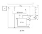
第1圖為本發明實施例中一種具自動洩流電流控制之可調光發光二極體照明系統100的功能方塊圖。發光二極體照明系統100包含一電源供應電路110、一調光開關120、一整流電路130、一洩流電路140,以及一發光單元150。FIG. 1 is a functional block diagram of a dimmable light emitting
電源供應電路110可提供一具正負週期之交流電壓VS,整流電路130可利用一橋式整流器來轉換交流電壓VS在負週期內之輸出電壓,因此可提供一整流交流電壓VAC以驅動發光二極體照明系統100,其中整流交流電壓VAC之值隨著時間而有週期性變化。然而,電源供應電路110和整流電路130之結構並不限定本發明之範疇。The
發光單元150包含複數個發光裝置和一驅動器。每一發光裝置可包含一個發光二極體,或是複數個串接之發光二極體。每一發光二極體可為單介面發光二極體(single-junction LED)、多介面高壓發光二極體(multi-junction high-voltage LED),或其它具類似功能之元件。然而,發光裝置之種類和組態並不限定本發明之範疇。The
第2圖為本發明實施例中具自動洩流電流控制之可調光發光二極體照明系統100中調光開關120之示意圖。第3圖為本發明實施例中具自動洩流電流控制之可調光發光二極體照明系統100中調光開關120運作時之示意圖。調光開關120可相位調變電源供應電路110以調整整流交流電壓VAC之責任週期,進而調整流經發光二極體照明系統100的系統電流ISYS之責任週期,因此能控制發光單元150所提供之光輸出量(光強度)。當未啟動調光開關120之功能時,供給至整流電路130之電壓VDIM其值和電源供應電路110提供之交流電壓VS相同;當啟動調光開關120之功能時,供給至整流電路130之電壓VDIM是透過依據調光輸入訊號SDIMMER相位調變整流交流電壓VAC來提供。Fig. 2 is a schematic diagram of the
在第2圖所示之實施例中,調光開關120為一相切(phase-cut)調光器,其包含一TRIAC元件22、一雙端觸發交流(DIAC)元件24、一可變電阻26,以及一電容28。TRIAC元件22和DIAC元件24為雙向切換元件,當開啟(被觸發)時能雙向導通電流。可變電阻26和電容28用來提供一觸發電壓VG,其相對於交流電壓VS具有一電阻-電容(RC)延遲時間。如第3圖所示,在週期內的關閉時段TOFF內,觸發電壓VG之值尚不足以開啟TRIAC元件22,因此交流電壓VS並不會供應至整流電路130(VDIM=0);在週期內的開啟時段TON內,當觸發電壓VG之值超過TRIAC元件22之臨界電壓時,TRIAC元件22會被開啟而傳導系統電流ISYS。只要系統電流ISYS之值維持在高於TRIAC元件22之最小保持電流之值,交流電壓VS即可被供應至整流電路130(電壓VDIM之波形隨著整流交流電壓VAC之波形而變化)。In the embodiment shown in Figure 2, the
在可調光發光二極體照明系統100中,調光開關120會依據接收到之調光輸入訊號SDIMMER來決定針對電源供應電路110之交流電壓VS的調整量。在一些實施例中,調光輸入訊號SDIMMER為類比訊號,可透過轉動開關、滑動開關,或任何能依據調整設定來提供一調整訊號之電性或機械式裝置來產生。在其它實施例中,調光輸入訊號SDIMMER可為數位訊號。然而,調光輸入訊號SDIMMER之實施方式並不限定本發明之範疇。In the dimmable
在第2圖所示之實施例中,可變電阻26之值可依據調光輸入訊號SDIMMER來加以調整,以改變觸發電壓VG相對於交流電壓VS之電阻-電容延遲時間,進而調整電壓VDIM之週期內開啟時段TON和關閉時段TOFF的長短。由於發光單元150之光輸出強度實質上正比於整流交流電壓VAC,而整流交流電壓VAC之值相關於電壓VDIM,因此流經發光單元150之系統電流ISYS能以調變方式被控制,使得發光單元150在反應調光輸入訊號SDIMMER時能提供平穩變化的光輸出強度,而不會造成可感受到的閃爍。In the embodiment shown in Figure 2, the value of the
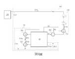
第4圖為本發明實施例具自動洩流電流控制之可調光發光二極體照明系統100中洩流電路140之示意圖。洩流電路140包含一電流源IS0、一調光偵測單元30,以及一調整單元40。電流源IS0可依據控制訊號S1來供應洩流電流IBL,以在需要時維持調光開關120的穩定運作。為了說明目的,在第4圖顯示之實施方式中,發光單元150之驅動器55可依據控制訊號S2來調節流經複數個發光裝置之LED電流ILED。在開機後,調光偵測單元30可監控整流交流電壓VAC之電壓準位,並因此提供相關於可調光發光二極體照明系統100之運作模式的一調光偵測訊號SD。調整單元40可依據調光偵測訊號SD來調整電流源IS0所供應洩流電流IBL之值,並輸出相關於整流交流電壓VAC之工作週期的控制訊號S2。FIG. 4 is a schematic diagram of the
第5圖至第7圖為本發明實施例具自動洩流電流控制之可調光發光二極體照明系統100中洩流電路140運作時之時序圖。在第5圖所示之實施例中,可調光發光二極體照明系統100是在非調光模式下運作,亦即並未啟動調光開關120的功能。在第6圖和第7圖所示之實施例中,可調光發光二極體照明系統100是在調光模式下運作,亦即有啟動調光開關120的功能。為了說明目的,t1~t8代表在整流交流電壓VAC之一個週期內按先後順序排列之不同時間點。5 to 7 are timing diagrams of the operation of the
在一實施例中,調光偵測單元30可偵測整流交流電壓VAC之值從0(一個週期的起始值)升至或超過一臨界電壓VH1所需之時間長度P0。若時間長度P0至少在整流交流電壓VAC之連續m個週期(m為正整數)內維持小於一臨界值(代表整流交流電壓VAC具較大工作週期),此時會判定可調光發光二極體照明系統100是在非調光模式下運作。若時間長度P0並未至少在整流交流電壓VAC之連續m個週期內維持小於臨界值(代表整流交流電壓VAC具較小工作週期),此時會判定可調光發光二極體照明系統100是在調光模式下運作。In one embodiment, the dimming
在第5圖並未啟動調光開關120功能之實施例中,供應至整流電路130之電壓VDIM和電源供應電路110所提供之整流電壓VS相同。此時,具100%工作週期之整流交流電壓VAC其值會在時間點t1達到VH1,使得偵測到之時間長度P0很短,因此調光偵測單元30會判定可調光發光二極體照明系統100是在非調光模式下運作。在此種情況下,調整單元40會關閉電流源IS0以停止供應洩流電流IBL。In the embodiment in FIG. 5 where the function of the
在第6圖和第7圖有啟動調光開關120功能之實施例中,供應至整流電路130之電壓VDIM是由依據調光輸入訊號SDIMMER來相位調變之整流電壓VS之方式來提供。為了說明目的,假設在第6圖中具大約65%工作週期之整流交流電壓VAC其值會在時間點t2超過VH1,而在第7圖中具大約35%工作週期之整流交流電壓VAC其值會在時間點t5超過VH1。由於第6圖和第7圖中整流交流電壓VAC之工作週期較短,其值會較慢達到或超過VH1,使得偵測到之時間長度P0很長,因此調光偵測單元30會判定可調光發光二極體照明系統100是在調光模式下運作。在此種情況下,調整單元40會開啟電流源IS0以供應洩流電流IBL,並指示電流源IS0在時段P1內將洩流電流IBL之值維持在IH,並在接續時段P1之時段P2內將洩流電流IBL之值維持在IL,其中IL<IH。同時,依據電流源IS0之輸出端上建立的回授電壓VFB1和整流交流電壓VAC之工作週期,調整單元40可依此調整電流IBL和ILED之加總。In the embodiment with the function of activating the
在第6圖所示之實施例中,當可調光發光二極體照明系統100收到相關於中等調光亮度之調光訊號SDIMMER時,整流交流電壓VAC會被相位調變至具有約65%之工作週期,此時發光單元150的導通時段(時間點t3和t6之間當ILED>0時)會大於時段P1(時間點t2和t4之間)。因此,調整單元40會指示電流源IS0在時段P1(時間點t2和t4之間)內供應電流值為IH之洩流電流IBL,以及在時段P2(時間點t4和t8之間)內供應電流值為IL之洩流電流IBL,其中IL<IH。如此一來,電流值為IH之洩流電流IBL可在時間點t2和t3之間維持調光開關120的穩定運作,洩流電流IBL和LED電流ILED可在時間點t3和t6之間維持調光開關120的穩定運作,而電流值為IL之洩流電流IBL可在時間點t6和t8之間維持調光開關120的穩定運作。In the embodiment shown in Figure 6, when the dimmable light emitting
在本發明中,當可調光發光二極體照明系統100在調光模式下運作時,洩流電流IBL之值在時段P1內會維持在IH,並在接續時段P1之時段P2內會維持在IL。在一實施例中,當可調光發光二極體照明系統100在調光模式下運作時,調整單元40會指示電流源IS0先在時段P1內供應電流值為IH之洩流電流IBL,接著在時段P2內停止供應洩流電流IBL(IL=0)。In the present invention, when the dimmable light emitting
在第7圖所示之實施例中,當可調光發光二極體照明系統100收到相關於低調光亮度之調光訊號SDIMMER時,整流交流電壓VAC會被相位調變至具有約35%之工作週期,此時發光單元150的導通時段(時間點t5和t6之間當ILED>0時)可能很短。因此,調整單元40會指示電流源IS0在時段P1(時間點t5和t7之間)內供應電流值為IH之洩流電流IBL,以及在時段P2(時間點t7和t8之間)內供應電流值為IL之洩流電流IBL,其中IL<IH。如此一來,洩流電流IBL和LED電流ILED可在時間點t5和t6之間維持調光開關120的穩定運作,電流值為IH之洩流電流IBL可在時間點t6和t7之間維持調光開關120的穩定運作,而電流值為IL之洩流電流IBL可在時間點t7和t8之間維持調光開關120的穩定運作。In the embodiment shown in Figure 7, when the dimmable light-emitting
如前所述,調整單元40可透過輸出相關於整流交流電壓VAC之工作週期的控制訊號S2來調節系統電流ISYS之值,進而指示驅動器55去調整LED電流ILED之值。在第6圖中當整流交流電壓VAC被相位調變至具有約65%之工作週期時,驅動器55會調節LED電流ILED之值以使系統電流ISYS之最大值會被箝制在一第一值I1。在第7圖中當整流交流電壓VAC會被相位調變至具有約35%之工作週期時,驅動器55會降低LED電流ILED之值以使系統電流ISYS之最大值會被箝制在一第二值I2,其中I2<I1。透過在低亮度調光時調低系統電流ISYS之值,本發明可讓肉眼更不容易感受到閃爍現象。As mentioned above, the
第8圖為本發明另一實施例中調光偵測單元30實作方式之示意圖。在此實施例中,調光偵測單元30包含2個電流源IS1-IS2、一電流偵測元件RCS,以及一電容CPD。在啟動後,調光偵測單元30可依據電流偵測元件RCS上的一回授電壓VFB1來監控整流交流電壓VAC之準位。在一實施例中,電流偵測元件RCS可為一電阻。然而,電流偵測元件RCS之實施方式並不限定本發明之範疇。FIG. 8 is a schematic diagram of the implementation of the dimming
當依據回授電壓VFB1判定整流交流電壓VAC之值已經達到或超過一預定值時,調光偵測單元30會開啟電流源IS1和關閉電流源IS2以充電電容CPD。當依據回授電壓VFB1判定整流交流電壓VAC之值並未達到或超過一預定值時,調光偵測單元30會關閉電流源IS1和開啟電流源IS2以放電電容CPD。When it is determined based on the feedback voltage VFB1 that the value of the rectified AC voltage VAC has reached or exceeds a predetermined value, the dimming
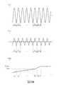
第9圖和第10圖為本發明實施例中具自動洩流電流控制之可調光發光二極體照明系統100運作時之電流-電壓特性圖。第9圖顯示了在未啟動調光開關120功能時整流交流電壓VAC之複數個週期內整流交流電壓VAC、系統電流ISYS和回授電壓VFB2之波形圖。第10圖顯示了在啟動調光開關120功能時整流交流電壓VAC之複數個週期內整流交流電壓VAC、系統電流ISYS和回授電壓VFB2之波形圖。Figures 9 and 10 are current-voltage characteristic diagrams of the dimmable light emitting
在第9圖中,假設系統電流ISYS之工作週期大於95%,電容CPD上的回授電壓VFB2在整流交流電壓VAC之週期T1-Tn中呈現鋸齒狀波形,其中其波形上升區段代表電容CPD之充電週期,而其波形下降區段代表電容CPD之放電週期。當透過調整電流源IS1和IS2之值以使電容CPD之充電量大於電容CPD之放電量時,電容CPD上的回授電壓VFB2會逐漸增加,如第9圖所示。當回授電壓VFB2在整流交流電壓VAC之週期Tn時達到一臨界電壓VH2時,調光偵測單元30會判定可調光發光二極體照明系統100是在非調光模式下運作。因此,調整單元40會將回授電壓VFB2箝制在大於臨界電壓VH2之一上限電壓VMAX,並關閉電流源IS0以停止供應洩流電流IBL,進而在不需要調光功能時降低系統電流ISYS以減少發光二極體照明系統100之功耗。In Figure 9, assuming that the duty cycle of the system current ISYS is greater than 95%, the feedback voltage VFB2 on the capacitor CPD presents a saw-tooth waveform in the cycle T1-Tn of the rectified AC voltage VAC , where the waveform rises The segment represents the charging period of the capacitor CPD , and the falling section of the waveform represents the discharge period of the capacitor CPD . When the value by adjusting the current sources IS1 and IS2 so that the charging capacitor CPD is greater than the amount of discharge of the capacitor CPD, the feedback voltage VFB2 will gradually increase in the capacitance CPD, as shown in Figure 9. When the feedback voltage VFB2 reaches a threshold voltage VH2 during the period Tn of the rectified AC voltage VAC , the dimming
在第10圖中,假設系統電流ISYS之工作週期小於90%,電容CPD上的回授電壓VFB2在整流交流電壓VAC之週期T1-Tn中呈現鋸齒狀波形,其中其波形上升區段代表電容CPD之充電週期,而其波形下降區段代表電容CPD之放電週期。當透過調整電流源IS1和IS2之值以使電容CPD之充電量小於電容CPD之放電量時,電容CPD上的回授電壓VFB2會維持在低於臨界電壓VH2之準位,如第10圖所示。當回授電壓VFB2維持在低於臨界電壓VH2之準位時,調光偵測單元30會判定可調光發光二極體照明系統100是在調光模式下運作。因此,調光偵測單元30會控制電流源IS0以在時段P1內供應電流值為IH之洩流電流IBL,以及在時段P2內供應電流值為IL之洩流電流IBL,如第6圖和第7圖所示。如此一來,本發明在需要調光功能時能確保系統電流ISYS之值維持在高於TRIAC裝置22的最小保持電流,進而確保發光二極體照明系統100之調光開關120能正常運作。In Figure 10, assuming that the duty cycle of the system current ISYS is less than 90%, the feedback voltage VFB2 on the capacitor CPD presents a saw-tooth waveform in the cycle T1-Tn of the rectified AC voltage VAC , where the waveform rises The segment represents the charging period of the capacitor CPD , and the falling section of the waveform represents the discharge period of the capacitor CPD . When the value by adjusting the current sources IS1 and IS2 so that the charging capacitor CPD is smaller than the amount of amount of discharge of the capacitor CPD, the feedback voltage VFB2 of the capacitor CPD will be maintained at a level lower than the threshold voltage VH2, As shown in Figure 10. When the feedback voltage VFB2 is maintained at a level lower than the threshold voltage VH2 , the dimming
綜上所述,本發明可透過監控整流交流電壓VAC之值來判斷是否需要供應洩流電流IBL。當判定發光二極體照明系統100是在調光模式下運作時,本發明會在第一時段內供應具第一電流值之洩流電流IBL,以及在第二時段內供應具第二電流值之洩流電流,進而確保系統電流ISYS之值維持在高於TRIAC裝置22的最小保持電流,以使發光二極體照明系統100之調光開關120能正常運作。同時,本發明會在低調光亮度的應用中降低系統電流ISYS之值,使得肉眼更不容易感受到閃爍現象。以上所述僅為本發明之較佳實施例,凡依本發明申請專利範圍所做之均等變化與修飾,皆應屬本發明之涵蓋範圍。In summary, the present invention can determine whether the leakage current IBL needs to be supplied by monitoring the value of the rectified AC voltage VAC . When it is determined that the
30:調光偵測單元30: Dimming detection unit
40:調整單元40: adjustment unit
55:驅動器55: drive
130:整流電路130: rectifier circuit
140:洩流電路140: bleeder circuit
150:發光單元150: light-emitting unit
IS0:電流源IS0: current source
VAC:整流交流電壓VAC : Rectified AC voltage
VFB1:回授電壓VFB1 : Feedback voltage
ILED:LED電流ILED : LED current
ISYS:系統電流ISYS : System current
IBL:洩流電流IBL : Leakage current
S1、S2:控制訊號S1, S2: control signal
Claims (12)
Translated fromChineseApplications Claiming Priority (4)
| Application Number | Priority Date | Filing Date | Title |
|---|---|---|---|
| US201862731969P | 2018-09-16 | 2018-09-16 | |
| US62/731,969 | 2018-09-16 | ||
| US16/558,326 | 2019-09-03 | ||
| US16/558,326US10531533B1 (en) | 2018-09-16 | 2019-09-03 | Light-emitting diode lighting system with automatic bleeder current control |
Publications (2)
| Publication Number | Publication Date |
|---|---|
| TW202014051A TW202014051A (en) | 2020-04-01 |
| TWI709359Btrue TWI709359B (en) | 2020-11-01 |
Family
ID=69058824
Family Applications (1)
| Application Number | Title | Priority Date | Filing Date |
|---|---|---|---|
| TW108132350ATWI709359B (en) | 2018-09-16 | 2019-09-09 | Light-emitting diode lighting system with automatic bleeder current control |
Country Status (3)
| Country | Link |
|---|---|
| US (1) | US10531533B1 (en) |
| CN (1) | CN110913529B (en) |
| TW (1) | TWI709359B (en) |
Families Citing this family (2)
| Publication number | Priority date | Publication date | Assignee | Title |
|---|---|---|---|---|
| CN112188681B (en)* | 2020-09-10 | 2023-04-07 | 昂宝电子(上海)有限公司 | LED drive system and its discharge current control circuit and control method |
| CN115379621A (en)* | 2021-05-21 | 2022-11-22 | 芯源创科技(深圳)有限公司 | Light-emitting diode lighting device with improved voltage regulation |
Citations (4)
| Publication number | Priority date | Publication date | Assignee | Title |
|---|---|---|---|---|
| TWM503722U (en)* | 2013-12-16 | 2015-06-21 | 立錡科技股份有限公司 | Light emitting device power supply circuit with dimming function and control circuit thereof |
| TW201542034A (en)* | 2014-04-25 | 2015-11-01 | Guangzhou On Bright Electronics Co Ltd | Lighting system and control method thereof |
| CN105493633A (en)* | 2013-05-10 | 2016-04-13 | 上海新进半导体制造有限公司 | Power supply for LED lamp with TRIAC dimmer |
| CN106912144A (en)* | 2017-04-06 | 2017-06-30 | 矽力杰半导体技术(杭州)有限公司 | LED drive circuit, circuit module and control method with controllable silicon dimmer |
Family Cites Families (5)
| Publication number | Priority date | Publication date | Assignee | Title |
|---|---|---|---|---|
| CN102148564B (en)* | 2010-02-10 | 2014-08-13 | 上海华虹宏力半导体制造有限公司 | Voltage conversion circuit |
| TWI489911B (en)* | 2011-12-30 | 2015-06-21 | Richtek Technology Corp | Active bleeder circuit triggering triac in all phase and light emitting device power supply circuit and triac control method using the active bleeder circuit |
| US9484814B2 (en)* | 2014-11-07 | 2016-11-01 | Power Integrations, Inc. | Power converter controller with analog controlled variable current circuit |
| KR102453820B1 (en)* | 2015-08-21 | 2022-10-17 | 서울반도체 주식회사 | Driving circuit and lighting apparatus for light emitting diode |
| US9769901B1 (en)* | 2016-06-14 | 2017-09-19 | Power Integrations, Inc. | Variable bleeder circuit |
- 2019
- 2019-09-03USUS16/558,326patent/US10531533B1/enactiveActive
- 2019-09-09TWTW108132350Apatent/TWI709359B/enactive
- 2019-09-16CNCN201910868732.5Apatent/CN110913529B/enactiveActive
Patent Citations (6)
| Publication number | Priority date | Publication date | Assignee | Title |
|---|---|---|---|---|
| CN105493633A (en)* | 2013-05-10 | 2016-04-13 | 上海新进半导体制造有限公司 | Power supply for LED lamp with TRIAC dimmer |
| TWM503722U (en)* | 2013-12-16 | 2015-06-21 | 立錡科技股份有限公司 | Light emitting device power supply circuit with dimming function and control circuit thereof |
| TW201542034A (en)* | 2014-04-25 | 2015-11-01 | Guangzhou On Bright Electronics Co Ltd | Lighting system and control method thereof |
| TWI573492B (en)* | 2014-04-25 | 2017-03-01 | Guangzhou On-Bright Electronics Co Ltd | Lighting system and its control method |
| CN106912144A (en)* | 2017-04-06 | 2017-06-30 | 矽力杰半导体技术(杭州)有限公司 | LED drive circuit, circuit module and control method with controllable silicon dimmer |
| CN106912144B (en) | 2017-04-06 | 2018-01-23 | 矽力杰半导体技术(杭州)有限公司 | LED drive circuit, circuit module and control method with controllable silicon dimmer |
Also Published As
| Publication number | Publication date |
|---|---|
| CN110913529B (en) | 2021-04-02 |
| TW202014051A (en) | 2020-04-01 |
| CN110913529A (en) | 2020-03-24 |
| US10531533B1 (en) | 2020-01-07 |
Similar Documents
| Publication | Publication Date | Title |
|---|---|---|
| US9307593B1 (en) | Dynamic bleeder current control for LED dimmers | |
| US8212494B2 (en) | Dimmer triggering circuit, dimmer system and dimmable device | |
| US8853954B2 (en) | Power supply for illumination and luminaire | |
| US7102902B1 (en) | Dimmer circuit for LED | |
| US9006999B2 (en) | Flickering suppressor system for a dimmable LED light bulb | |
| TWI420960B (en) | Led drive circuit, dimming device, led illumination fixture, led illumination device, and led illumination system | |
| CN102655701B (en) | Illuminator | |
| JP5441638B2 (en) | Light control device | |
| JP5975375B2 (en) | 2-wire dimmer switch | |
| CN102378450A (en) | Led driver circuit and led lighting device using the same | |
| TW201328432A (en) | Active bleeder circuit triggering TRIAC in all phase and light emitting device power supply circuit and TRIAC control method using the active bleeder circuit | |
| TWI709359B (en) | Light-emitting diode lighting system with automatic bleeder current control | |
| CN110446294B (en) | LED lighting system with automatic dimming control | |
| US10334682B1 (en) | Light-emitting diode lighting system with automatic bleeder current control | |
| EP2890220B1 (en) | Bleeder circuit controller | |
| CN111356258B (en) | Light modulation circuit applied to light emitting diode lighting system | |
| KR101349516B1 (en) | Power device for led lighting | |
| CN204986459U (en) | Light emitting diode lamp | |
| CN108882430A (en) | LED lamp with automatic light-adjusting function | |
| TWI622320B (en) | Light-emitting diode lamp with automatic dimming function | |
| JP2016001619A (en) | 2-wire dimmer switch |