TWI708127B - Cartridge - Google Patents
CartridgeDownload PDFInfo
- Publication number
- TWI708127B TWI708127BTW108123098ATW108123098ATWI708127BTW I708127 BTWI708127 BTW I708127BTW 108123098 ATW108123098 ATW 108123098ATW 108123098 ATW108123098 ATW 108123098ATW I708127 BTWI708127 BTW I708127B
- Authority
- TW
- Taiwan
- Prior art keywords
- force
- force receiving
- movable member
- roller
- developing roller
- Prior art date
Links
- 230000008878couplingEffects0.000claimsdescription40
- 238000010168coupling processMethods0.000claimsdescription40
- 238000005859coupling reactionMethods0.000claimsdescription40
- 230000033001locomotionEffects0.000abstractdescription53
- 238000000034methodMethods0.000abstractdescription14
- 230000008569processEffects0.000abstractdescription14
- 238000012545processingMethods0.000description112
- 230000007246mechanismEffects0.000description29
- 230000005540biological transmissionEffects0.000description15
- 239000000463materialSubstances0.000description11
- 238000009434installationMethods0.000description8
- 230000001105regulatory effectEffects0.000description8
- 238000004140cleaningMethods0.000description6
- 238000011144upstream manufacturingMethods0.000description6
- 230000008859changeEffects0.000description4
- 239000003086colorantSubstances0.000description4
- 230000002093peripheral effectEffects0.000description4
- 238000000926separation methodMethods0.000description4
- 230000000694effectsEffects0.000description3
- 230000004048modificationEffects0.000description3
- 238000012986modificationMethods0.000description3
- 230000015572biosynthetic processEffects0.000description2
- 230000005489elastic deformationEffects0.000description2
- 238000000605extractionMethods0.000description2
- 238000005192partitionMethods0.000description2
- 238000002360preparation methodMethods0.000description2
- 230000002265preventionEffects0.000description2
- 238000012546transferMethods0.000description2
- 238000011161developmentMethods0.000description1
- 238000003384imaging methodMethods0.000description1
- 230000006872improvementEffects0.000description1
- 238000003780insertionMethods0.000description1
- 230000037431insertionEffects0.000description1
- 238000012423maintenanceMethods0.000description1
- 239000002245particleSubstances0.000description1
- 239000000049pigmentSubstances0.000description1
- 125000006850spacer groupChemical group0.000description1
- 239000001060yellow colorantSubstances0.000description1
Images


Classifications
- G—PHYSICS
- G03—PHOTOGRAPHY; CINEMATOGRAPHY; ANALOGOUS TECHNIQUES USING WAVES OTHER THAN OPTICAL WAVES; ELECTROGRAPHY; HOLOGRAPHY
- G03G—ELECTROGRAPHY; ELECTROPHOTOGRAPHY; MAGNETOGRAPHY
- G03G21/00—Arrangements not provided for by groups G03G13/00 - G03G19/00, e.g. cleaning, elimination of residual charge
- G03G21/16—Mechanical means for facilitating the maintenance of the apparatus, e.g. modular arrangements
- G03G21/18—Mechanical means for facilitating the maintenance of the apparatus, e.g. modular arrangements using a processing cartridge, whereby the process cartridge comprises at least two image processing means in a single unit
- G03G21/1803—Arrangements or disposition of the complete process cartridge or parts thereof
- G03G21/1814—Details of parts of process cartridge, e.g. for charging, transfer, cleaning, developing
- G—PHYSICS
- G03—PHOTOGRAPHY; CINEMATOGRAPHY; ANALOGOUS TECHNIQUES USING WAVES OTHER THAN OPTICAL WAVES; ELECTROGRAPHY; HOLOGRAPHY
- G03G—ELECTROGRAPHY; ELECTROPHOTOGRAPHY; MAGNETOGRAPHY
- G03G15/00—Apparatus for electrographic processes using a charge pattern
- G—PHYSICS
- G03—PHOTOGRAPHY; CINEMATOGRAPHY; ANALOGOUS TECHNIQUES USING WAVES OTHER THAN OPTICAL WAVES; ELECTROGRAPHY; HOLOGRAPHY
- G03G—ELECTROGRAPHY; ELECTROPHOTOGRAPHY; MAGNETOGRAPHY
- G03G15/00—Apparatus for electrographic processes using a charge pattern
- G03G15/02—Apparatus for electrographic processes using a charge pattern for laying down a uniform charge, e.g. for sensitising; Corona discharge devices
- G—PHYSICS
- G03—PHOTOGRAPHY; CINEMATOGRAPHY; ANALOGOUS TECHNIQUES USING WAVES OTHER THAN OPTICAL WAVES; ELECTROGRAPHY; HOLOGRAPHY
- G03G—ELECTROGRAPHY; ELECTROPHOTOGRAPHY; MAGNETOGRAPHY
- G03G21/00—Arrangements not provided for by groups G03G13/00 - G03G19/00, e.g. cleaning, elimination of residual charge
- G03G21/16—Mechanical means for facilitating the maintenance of the apparatus, e.g. modular arrangements
- G03G21/1604—Arrangement or disposition of the entire apparatus
- G03G21/1623—Means to access the interior of the apparatus
- G—PHYSICS
- G03—PHOTOGRAPHY; CINEMATOGRAPHY; ANALOGOUS TECHNIQUES USING WAVES OTHER THAN OPTICAL WAVES; ELECTROGRAPHY; HOLOGRAPHY
- G03G—ELECTROGRAPHY; ELECTROPHOTOGRAPHY; MAGNETOGRAPHY
- G03G21/00—Arrangements not provided for by groups G03G13/00 - G03G19/00, e.g. cleaning, elimination of residual charge
- G03G21/16—Mechanical means for facilitating the maintenance of the apparatus, e.g. modular arrangements
- G03G21/1642—Mechanical means for facilitating the maintenance of the apparatus, e.g. modular arrangements for connecting the different parts of the apparatus
- G03G21/1647—Mechanical connection means
- G—PHYSICS
- G03—PHOTOGRAPHY; CINEMATOGRAPHY; ANALOGOUS TECHNIQUES USING WAVES OTHER THAN OPTICAL WAVES; ELECTROGRAPHY; HOLOGRAPHY
- G03G—ELECTROGRAPHY; ELECTROPHOTOGRAPHY; MAGNETOGRAPHY
- G03G21/00—Arrangements not provided for by groups G03G13/00 - G03G19/00, e.g. cleaning, elimination of residual charge
- G03G21/16—Mechanical means for facilitating the maintenance of the apparatus, e.g. modular arrangements
- G03G21/1661—Mechanical means for facilitating the maintenance of the apparatus, e.g. modular arrangements means for handling parts of the apparatus in the apparatus
- G03G21/1676—Mechanical means for facilitating the maintenance of the apparatus, e.g. modular arrangements means for handling parts of the apparatus in the apparatus for the developer unit
- G—PHYSICS
- G03—PHOTOGRAPHY; CINEMATOGRAPHY; ANALOGOUS TECHNIQUES USING WAVES OTHER THAN OPTICAL WAVES; ELECTROGRAPHY; HOLOGRAPHY
- G03G—ELECTROGRAPHY; ELECTROPHOTOGRAPHY; MAGNETOGRAPHY
- G03G21/00—Arrangements not provided for by groups G03G13/00 - G03G19/00, e.g. cleaning, elimination of residual charge
- G03G21/16—Mechanical means for facilitating the maintenance of the apparatus, e.g. modular arrangements
- G03G21/18—Mechanical means for facilitating the maintenance of the apparatus, e.g. modular arrangements using a processing cartridge, whereby the process cartridge comprises at least two image processing means in a single unit
- G03G21/1803—Arrangements or disposition of the complete process cartridge or parts thereof
- G03G21/1817—Arrangements or disposition of the complete process cartridge or parts thereof having a submodular arrangement
- G03G21/1825—Pivotable subunit connection
- G—PHYSICS
- G03—PHOTOGRAPHY; CINEMATOGRAPHY; ANALOGOUS TECHNIQUES USING WAVES OTHER THAN OPTICAL WAVES; ELECTROGRAPHY; HOLOGRAPHY
- G03G—ELECTROGRAPHY; ELECTROPHOTOGRAPHY; MAGNETOGRAPHY
- G03G21/00—Arrangements not provided for by groups G03G13/00 - G03G19/00, e.g. cleaning, elimination of residual charge
- G03G21/16—Mechanical means for facilitating the maintenance of the apparatus, e.g. modular arrangements
- G03G21/18—Mechanical means for facilitating the maintenance of the apparatus, e.g. modular arrangements using a processing cartridge, whereby the process cartridge comprises at least two image processing means in a single unit
- G03G21/1839—Means for handling the process cartridge in the apparatus body
- G03G21/1842—Means for handling the process cartridge in the apparatus body for guiding and mounting the process cartridge, positioning, alignment, locks
- G—PHYSICS
- G03—PHOTOGRAPHY; CINEMATOGRAPHY; ANALOGOUS TECHNIQUES USING WAVES OTHER THAN OPTICAL WAVES; ELECTROGRAPHY; HOLOGRAPHY
- G03G—ELECTROGRAPHY; ELECTROPHOTOGRAPHY; MAGNETOGRAPHY
- G03G2215/00—Apparatus for electrophotographic processes
- G03G2215/01—Apparatus for electrophotographic processes for producing multicoloured copies
- G03G2215/0103—Plural electrographic recording members
- G03G2215/0119—Linear arrangement adjacent plural transfer points
- G—PHYSICS
- G03—PHOTOGRAPHY; CINEMATOGRAPHY; ANALOGOUS TECHNIQUES USING WAVES OTHER THAN OPTICAL WAVES; ELECTROGRAPHY; HOLOGRAPHY
- G03G—ELECTROGRAPHY; ELECTROPHOTOGRAPHY; MAGNETOGRAPHY
- G03G2221/00—Processes not provided for by group G03G2215/00, e.g. cleaning or residual charge elimination
- G03G2221/16—Mechanical means for facilitating the maintenance of the apparatus, e.g. modular arrangements and complete machine concepts
- G03G2221/1678—Frame structures
- G03G2221/169—Structural door designs
- G—PHYSICS
- G03—PHOTOGRAPHY; CINEMATOGRAPHY; ANALOGOUS TECHNIQUES USING WAVES OTHER THAN OPTICAL WAVES; ELECTROGRAPHY; HOLOGRAPHY
- G03G—ELECTROGRAPHY; ELECTROPHOTOGRAPHY; MAGNETOGRAPHY
- G03G2221/00—Processes not provided for by group G03G2215/00, e.g. cleaning or residual charge elimination
- G03G2221/16—Mechanical means for facilitating the maintenance of the apparatus, e.g. modular arrangements and complete machine concepts
- G03G2221/18—Cartridge systems
- G03G2221/183—Process cartridge
- G03G2221/1853—Process cartridge having a submodular arrangement
- G03G2221/1861—Rotational subunit connection
- G—PHYSICS
- G03—PHOTOGRAPHY; CINEMATOGRAPHY; ANALOGOUS TECHNIQUES USING WAVES OTHER THAN OPTICAL WAVES; ELECTROGRAPHY; HOLOGRAPHY
- G03G—ELECTROGRAPHY; ELECTROPHOTOGRAPHY; MAGNETOGRAPHY
- G03G2221/00—Processes not provided for by group G03G2215/00, e.g. cleaning or residual charge elimination
- G03G2221/16—Mechanical means for facilitating the maintenance of the apparatus, e.g. modular arrangements and complete machine concepts
- G03G2221/18—Cartridge systems
- G03G2221/183—Process cartridge
- G03G2221/1853—Process cartridge having a submodular arrangement
- G03G2221/1869—Cartridge holders, e.g. intermediate frames for placing cartridge parts therein
Landscapes
- Physics & Mathematics (AREA)
- General Physics & Mathematics (AREA)
- Engineering & Computer Science (AREA)
- Computer Vision & Pattern Recognition (AREA)
- Plasma & Fusion (AREA)
- Electrophotography Configuration And Component (AREA)
- Wet Developing In Electrophotography (AREA)
- Dry Development In Electrophotography (AREA)
- Apparatus For Radiation Diagnosis (AREA)
Abstract
Description
Translated fromChinese本發明係關於處理匣,其中電子攝影光敏滾筒及可作用在電子攝影光敏滾筒上之顯影滾輪,可相互接觸及隔開,及該處理匣可拆卸地安裝至其上之電子攝影影像形成設備。The present invention relates to a processing cartridge, in which an electrophotographic photosensitive drum and a developing roller that can act on the electrophotographic photosensitive drum can be contacted and separated from each other, and the processing cartridge is detachably mounted on an electrophotographic image forming device.
於使用電子攝影影像形成處理之影像形成設備中,處理匣型係習知,其中電子攝影光敏滾筒及可作用在電子攝影光敏滾筒上之顯影滾輪被整合成可拆卸地安裝至影像形成設備的主總成之處理匣。至於處理匣型,設備的維護操作可被有效地實施而無需服務人員。因此,處理匣型被廣泛地使用於電子攝影影像形成設備的領域。In image forming equipment using electrophotographic image forming processing, the processing cartridge type is conventionally known, in which the electrophotographic photosensitive drum and the developing roller that can act on the electrophotographic photosensitive drum are integrated into the main body of the image forming apparatus detachably The processing box of the assembly. As for the processing cassette type, the maintenance operation of the equipment can be effectively implemented without the need for service personnel. Therefore, the processing cartridge type is widely used in the field of electrophotographic image forming equipment.
當影像形成操作被實施時,顯影滾輪被保持在預定壓力而推向電子攝影光敏滾筒。於顯影滾輪在顯影操作期接觸到光敏滾筒之接觸顯影系統中,顯影滾輪的彈性層在預定壓力而接觸到光敏滾筒的表面。When the image forming operation is performed, the developing roller is held at a predetermined pressure and pushed toward the electrophotographic photosensitive drum. In the contact developing system in which the developing roller contacts the photosensitive roller during the developing operation period, the elastic layer of the developing roller contacts the surface of the photosensitive roller under a predetermined pressure.
因此,當處理匣未被使用於處理匣保持安裝至影像形 成設備的主總成的長期間時,顯影滾輪的彈性層可能會變形。如果發生,不均勻性可能產生於所形成的影像。因為顯影滾輪接觸到光敏滾筒,顯影劑可能自顯影滾輪沉積至光敏滾筒。甚至當顯影操作未被實施時,光敏滾筒及顯影滾輪係相互接觸而旋轉。Therefore, when the process cartridge is not used for a long period of time while the process cartridge remains mounted to the main assembly of the image forming apparatus, the elastic layer of the developing roller may be deformed. If it does, unevenness may be generated in the image formed. Because the developing roller contacts the photosensitive roller, the developer may be deposited from the developing roller to the photosensitive roller. Even when the developing operation is not performed, the photosensitive roller and the developing roller are in contact with each other to rotate.
作為解決該問題之結構,提供一影像形成設備,其中當影像形成操作未被實施時,一機構作用在處理匣上以使顯影滾輪與電子攝影光敏滾筒隔開(日本專利先行公開案2003-167499)。As a structure to solve this problem, there is provided an image forming apparatus in which when the image forming operation is not performed, a mechanism acts on the process cartridge to separate the developing roller from the electrophotographic photosensitive roller (Japanese Patent Laid-open No. 2003-167499 ).
於揭示於此公開案之設備,四個處理匣可拆卸地安裝至影像形成設備的主總成。處理匣包含具有光敏滾筒之光敏構件單元、及用於支承可擺動地設於光敏構件單元之顯影滾輪。藉由運動設於影像形成設備的主總成之間隔板,設於顯影單元之力接收部接收來自間隔板之力。藉由相對於光敏構件單元來運動顯影單元,顯影滾輪自光敏滾筒而移開。In the equipment disclosed in this publication, four processing cartridges are detachably mounted to the main assembly of the image forming equipment. The processing cartridge includes a photosensitive member unit with a photosensitive drum, and a development roller for supporting the photosensitive member unit to be swingable. By moving the partition between the main assembly of the image forming device, the force receiving part provided in the developing unit receives the force from the partition plate. By moving the developing unit relative to the photosensitive member unit, the developing roller is moved away from the photosensitive roller.
於習知實例中,用於使顯影滾輪與光敏滾筒隔開之力接收部係自顯影單元的外構形而突起。因此,當使用者操作處理匣時,及/或當處理匣被運送時,力接收部可能受損。力接收部的存在可能有礙於處理匣的縮小,其中電子攝影光敏滾筒及顯影滾輪可相互接觸及相互隔開,且處理匣可拆卸地安裝至影像形成設備的主總成。In the conventional example, the force receiving part for separating the developing roller from the photosensitive roller protrudes from the outer configuration of the developing unit. Therefore, when the user manipulates the processing cassette, and/or when the processing cassette is transported, the force receiving portion may be damaged. The existence of the force receiving part may hinder the shrinkage of the processing cartridge, wherein the electrophotographic photosensitive drum and the developing roller can contact and be separated from each other, and the processing cartridge can be detachably mounted to the main assembly of the image forming apparatus.
因此,本發明的主要目的在於提供縮小的處理匣,其中電子攝影光敏滾筒及顯影滾輪可相互接觸及相互隔開,及處理匣可拆卸地安裝至電子攝影影像形成設備之尺寸縮小。Therefore, the main purpose of the present invention is to provide a reduced processing cartridge, in which the electrophotographic photosensitive drum and the developing roller can be in contact with and separated from each other, and the processing cartridge can be detachably mounted to the electrophotographic image forming equipment to reduce the size.
本發明的另一目的在於提供處理匣,其中電子攝影光敏滾筒及顯影滾輪可相互接觸及相互隔開,藉此,當處理匣被操作時,或當處理匣被運送時,力接收部不會受損。Another object of the present invention is to provide a process cartridge in which the electrophotographic photosensitive roller and the developing roller can be in contact with and separated from each other, whereby the force receiving part will not be able to be moved when the process cartridge is operated or when the process cartridge is transported. Damaged.
依據本發明的態樣提供一種處理匣,可拆卸地安裝於電子攝影影像形成設備的主總成,該主總成包括開口、可運動在用來關閉該開口之關閉位置及用來開啟該開口之開啟位置間的門、可隨著該門自該開啟位置至該關閉位置的運動而運動之第一施力構件、及可藉由來自驅動源的驅動力而運動第二施力構件,該處理匣包含:電子攝影光敏滾筒;顯影滾輪,用於使形成在該電子攝影光敏滾筒上之靜電潛像顯影;滾筒單元,含有該電子攝影光敏滾筒;顯影單元,該顯影單元含有該顯影滾輪,以及該顯影單元可相對於該滾筒單元而運動,使得該顯影滾輪可運動在該顯影滾輪接觸到該電子攝影光敏滾筒之接觸位置及該顯影滾輪與該電子攝影光敏滾筒隔開之隔開位置之間;及力接收裝置,第一力接收部包括及第二力接收部,於該處理匣經由該開口安裝至該設備主總成的狀態,該第一力接收部藉由該門自該開啟位置至該關閉位置的運動來接收來自該第一施力構件之力,以及透過該第一力接收部藉由接收自該第一施力構件之力的運動,該第二力接收部可自準備位置而 運動,其中該第二力接收部採取用於接收來自該第二施力構件之力的突出位置,以使該顯影單元自該接觸位置運動至該隔開位置,該突出位置係高於該準備位置。According to an aspect of the present invention, there is provided a processing cartridge which is detachably mounted on a main assembly of an electrophotographic image forming apparatus. The main assembly includes an opening, movable in a closed position for closing the opening, and for opening the opening The door between the open positions, the first force applying member that can move with the movement of the door from the open position to the closed position, and the second force applying member that can be moved by the driving force from the driving source, the The processing cartridge includes: an electrophotographic photosensitive roller; a developing roller for developing the electrostatic latent image formed on the electrophotographic photosensitive roller; a roller unit containing the electrophotographic photosensitive roller; a developing unit, the developing unit containing the developing roller, And the developing unit can move relative to the roller unit, so that the developing roller can move between the contact position where the developing roller contacts the electrophotographic photosensitive roller and the separation position between the developing roller and the electrophotographic photosensitive roller Between; and a force receiving device, the first force receiving portion includes and a second force receiving portion, in the state that the processing box is installed to the main assembly of the equipment through the opening, the first force receiving portion is opened by the door Position to the closed position to receive the force from the first force applying member, and through the movement of the first force receiving portion by the force received from the first force applying member, the second force receiving portion can automatically Move to the ready position, wherein the second force receiving portion adopts a protruding position for receiving the force from the second urging member, so that the developing unit moves from the contact position to the spaced position, and the protruding position is high In the ready position.
依據本發明的另一態樣提供一種電子攝影影像形成設備,用於形成影像在記錄材料上,處理匣係可拆卸地安裝於該設備,該設備包含:開口;門,可運動在用於關閉該開口之關閉位置及用於開啟該開口之開啟位置之間;第一施力構件,可隨著該門的運動自該開啟位置運動至該關閉位置;第二施力構件,可藉由來自驅動源的驅動力而運動;安裝機構,用於可拆卸地安裝處理匣,該處理匣包括:電子攝影光敏滾筒;顯影滾輪,用於使形成在該電子攝影光敏滾筒上之靜電潛像顯影;滾筒單元,含有該電子攝影光敏滾筒;顯影單元,該顯影單元含有該顯影滾輪,以及該顯影單元可相對於該滾筒單元而運動,使得該顯影滾輪可運動在該顯影滾輪接觸到該電子攝影光敏滾筒之接觸位置及該顯影滾輪與該電子攝影光敏滾筒隔開之隔開位置之間;及力接收裝置,第一力接收部包括及第二力接收部,於該處理匣經由該開口安裝至該設備主總成的狀態,該第一力接收部藉由該門自該開啟位置至該關閉位置的運動來接收來自該第一施力構件之力,以及透過該第一力接收部藉由接收自該第一施力構件之力的運動,該第二力接收部可自準備位置而運動,其中該第二力接收部採取用於接收來自該第二施力構件之力的突出位置,以使該顯影單元自該接觸位置運動至該隔開位置,該突出位置係高於該 準備位置;及進給機構,用於進給該記錄材料。According to another aspect of the present invention, there is provided an electrophotographic image forming apparatus for forming an image on a recording material. A processing cartridge is detachably mounted on the apparatus. The apparatus includes: an opening; a door movable for closing Between the closed position of the opening and the open position for opening the opening; the first force applying member can move from the open position to the closed position along with the movement of the door; the second force applying member can be The driving force of the driving source moves; the installation mechanism is used to detachably install the processing cartridge, the processing cartridge includes: an electrophotographic photosensitive drum; a developing roller for developing the electrostatic latent image formed on the electrophotographic photosensitive drum; A roller unit containing the electrophotographic photosensitive roller; a developing unit, the developing unit containing the developing roller, and the developing unit can move relative to the roller unit, so that the developing roller can move when the developing roller contacts the electrophotographic photosensitive roller Between the contact position of the roller and the separation position between the developing roller and the electrophotographic photosensitive roller; and a force receiving device, the first force receiving portion includes and a second force receiving portion, and the processing cartridge is mounted to the processing cartridge through the opening The state of the main assembly of the equipment, the first force receiving part receives the force from the first force applying member through the movement of the door from the open position to the closed position, and through the first force receiving part Receiving the movement of the force from the first force applying member, the second force receiving portion can move from a ready position, wherein the second force receiving portion adopts a protruding position for receiving the force from the second force applying member, In order to move the developing unit from the contact position to the spaced position, the protruding position is higher than the preparation position; and a feeding mechanism for feeding the recording material.
在考慮到本發明的較佳實施例的以下說明以及附圖之後,本發明的此些及其它目的、特徵及優點將更為顯而易見。These and other objects, features, and advantages of the present invention will be more apparent after considering the following description of the preferred embodiments of the present invention and the accompanying drawings.
P‧‧‧記錄材料P‧‧‧Recording materials
g‧‧‧力g‧‧‧force
H‧‧‧力矩H‧‧‧Moment
f2‧‧‧間隙f2‧‧‧Gap
D1、D2‧‧‧水平方向D1, D2‧‧‧Horizontal direction
z1‧‧‧方向z1‧‧‧direction
y1‧‧‧箭頭y1‧‧‧Arrow
z2‧‧‧方向z2‧‧‧direction
62e‧‧‧凸部62e‧‧‧Protrusion
62e‧‧‧鉤部62e‧‧‧hook
61e‧‧‧推動部61e‧‧‧Promotion Department
L‧‧‧箭頭L‧‧‧Arrow
f1‧‧‧間隙f1‧‧‧Gap
f2‧‧‧間隙f2‧‧‧Gap
α‧‧‧間隙α‧‧‧Gap
I‧‧‧距離I‧‧‧Distance
II‧‧‧距離II‧‧‧Distance
g‧‧‧間隙g‧‧‧Gap
γ‧‧‧間隙γ‧‧‧Gap
δ‧‧‧間隙δ‧‧‧Gap
λ‧‧‧間隙λ‧‧‧Gap
1‧‧‧進給滾輪(進給機構)1‧‧‧Feed roller (feed mechanism)
3‧‧‧傳輸滾輪3‧‧‧Transmission roller
6‧‧‧定影單元6‧‧‧Fixing Unit
7‧‧‧排放滾輪7‧‧‧Discharge roller
9‧‧‧排放部9‧‧‧Emissions Department
10‧‧‧雷射掃瞄器10‧‧‧Laser Scanner
11‧‧‧雷射光束11‧‧‧Laser beam
12‧‧‧門12‧‧‧door
12a‧‧‧旋轉中心12a‧‧‧Rotation Center
13‧‧‧匣托架13‧‧‧Tray holder
13a‧‧‧旋轉防止部13a‧‧‧Rotation prevention part
14‧‧‧托架固持構件14‧‧‧Bracket holding member
14c2‧‧‧下端14c2‧‧‧Bottom
14c1‧‧‧上端14c1‧‧‧Upper
14c‧‧‧細長孔14c‧‧‧Slim hole
14d1、14d2‧‧‧凸部14d1, 14d2‧‧‧Protrusion
14b‧‧‧細長孔14b‧‧‧Slim hole
15‧‧‧嚙合部15‧‧‧Meshing part
18y、18m、18c、18k‧‧‧傳輸滾輪18y, 18m, 18c, 18k‧‧‧Transmission roller
19‧‧‧傳輸皮帶19‧‧‧Transmission belt
30y、30m、30c、30k‧‧‧光敏滾筒30y, 30m, 30c, 30k‧‧‧Photosensitive roller
30‧‧‧光敏滾筒30‧‧‧Photosensitive roller
30a‧‧‧耦合構件30a‧‧‧Coupling component
31‧‧‧滾筒單元31‧‧‧Drum unit
31a‧‧‧凸部31a‧‧‧Protrusion
31y‧‧‧滾筒單元31y‧‧‧Drum unit
32‧‧‧充電滾輪32‧‧‧Charging roller
33‧‧‧刮片(清潔機構)33‧‧‧Scraper (cleaning mechanism)
34‧‧‧滾筒架34‧‧‧roller frame
35‧‧‧剩餘色料容置部35‧‧‧Remaining color material container
36、37‧‧‧覆蓋構件36、37‧‧‧covering member
36b‧‧‧支承部36b‧‧‧Support
36a、37a‧‧‧支承孔部36a, 37a‧‧‧Support hole
36d‧‧‧軸36d‧‧‧Axis
37b‧‧‧支承部37b‧‧‧Support
41‧‧‧顯影單元41‧‧‧Developing unit
42‧‧‧顯影滾輪42‧‧‧Developing roller
43‧‧‧顯影刮片43‧‧‧Developing blade
45‧‧‧軸承單元45‧‧‧Bearing unit
45b‧‧‧引導部45b‧‧‧Guide Department
45a‧‧‧引導部45a‧‧‧Guide Department
46‧‧‧覆蓋構件46‧‧‧covering member
46b‧‧‧圓柱部46b‧‧‧Cylinder part
48‧‧‧顯影裝置架48‧‧‧Developing device frame
48b‧‧‧突出部48b‧‧‧Protrusion
49‧‧‧色料容置部49‧‧‧Color material containing part
50y、50m、50c、50k‧‧‧處理匣(匣)50y, 50m, 50c, 50k‧‧‧Disposal cassette (cassette)
55‧‧‧支承軸55‧‧‧Support shaft
60‧‧‧第二施力構件60‧‧‧Second force application member
60b‧‧‧運動力接收部60b‧‧‧Motion force receiving part
60y‧‧‧(嚙合)肋部60y‧‧‧(engaging) rib
60c‧‧‧細長孔部60c‧‧‧Slim hole
60k、60c、60m‧‧‧嚙合肋部60k、60c、60m‧‧‧engaging rib
61e‧‧‧推動部61e‧‧‧Promotion Department
61‧‧‧第一施力構件61‧‧‧First force application member
61d‧‧‧支承孔61d‧‧‧Support hole
61f‧‧‧突出部61f‧‧‧Protrusion
61k、61c、61m‧‧‧第一施力構件61k, 61c, 61m‧‧‧First force application member
62‧‧‧連接構件62‧‧‧Connecting member
62c‧‧‧支承孔62c‧‧‧Support hole
62b‧‧‧支承銷62b‧‧‧Support pin
62a‧‧‧孔62a‧‧‧hole
62f‧‧‧凸部62f‧‧‧Protrusion
62g‧‧‧突出部62g‧‧‧Protrusion
66‧‧‧彈簧66‧‧‧Spring
66b‧‧‧一端66b‧‧‧One end
67‧‧‧耦合構件67‧‧‧Coupling component
67a‧‧‧耦合部67a‧‧‧Coupling part
68‧‧‧惰輪68‧‧‧Idler
69‧‧‧顯影滾輪齒輪69‧‧‧Developing roller gear
70‧‧‧第二力接收構件70‧‧‧Second force receiving member
70a‧‧‧軸70a‧‧‧Axis
70c‧‧‧凸輪表面70c‧‧‧Cam surface
70b‧‧‧側表面70b‧‧‧Side surface
70d‧‧‧間隔力接收部70d‧‧‧Interval force receiving part
73‧‧‧彈簧(推動機構)73‧‧‧Spring (Pushing mechanism)
75‧‧‧第一力接收構件75‧‧‧First force receiving member
75d‧‧‧嚙合部75d‧‧‧meshing part
75a‧‧‧被推動部75a‧‧‧Propelled Department
75b‧‧‧推動部75b‧‧‧Promotion Department
75c‧‧‧彈性部75c‧‧‧Flexible part
76‧‧‧彈簧76‧‧‧Spring
80‧‧‧開口80‧‧‧Open
90‧‧‧力接收裝置90‧‧‧Force receiving device
95‧‧‧推動彈簧(彈性構件)95‧‧‧Pushing spring (elastic member)
100‧‧‧電子攝影影像形成設備(設備主總成)100‧‧‧Electronic photographic image forming equipment (equipment main assembly)
101a‧‧‧定位部101a‧‧‧Positioning part
105‧‧‧第一主總成耦合構件105‧‧‧First main assembly coupling member
106‧‧‧第二主總成耦合構件106‧‧‧Second main assembly coupling member
107‧‧‧引導狹縫或槽部107‧‧‧Guide slit or groove
107a1‧‧‧水平部107a1‧‧‧Horizontal section
107a2‧‧‧傾斜部107a2‧‧‧inclined part
107a3‧‧‧水平部107a3‧‧‧Horizontal section
110‧‧‧馬達(驅動源)110‧‧‧Motor (drive source)
111‧‧‧齒輪111‧‧‧Gear
112‧‧‧齒輪112‧‧‧Gear
112a‧‧‧凸輪部112a‧‧‧Cam
150y‧‧‧匣150y‧‧‧Box
164‧‧‧第二施力構件164‧‧‧Second force applying member
165‧‧‧第一施力構件165‧‧‧First force application member
165a‧‧‧滑動部165a‧‧‧Sliding part
178‧‧‧第二力接收構件178‧‧‧Second force receiving member
179‧‧‧第一力接收構件179‧‧‧First force receiving member
179a‧‧‧滑動部179a‧‧‧Sliding part
190‧‧‧力接收裝置190‧‧‧Force receiving device
230‧‧‧電子攝影光敏滾筒230‧‧‧Electronic photography photosensitive drum
231‧‧‧滾筒單元231‧‧‧Drum unit
241‧‧‧顯影單元241‧‧‧Developing unit
242‧‧‧顯影滾輪242‧‧‧Developing roller
246b‧‧‧連接部246b‧‧‧Connecting part
248‧‧‧顯影裝置架248‧‧‧Developing device frame
248a‧‧‧鎖固部248a‧‧‧Locking part
250y‧‧‧黃色匣250y‧‧‧Yellow box
261‧‧‧第一施力構件261‧‧‧First force application member
262‧‧‧第一施力構件262‧‧‧First force application member
262a‧‧‧自由端部262a‧‧‧Free end
263‧‧‧第二施力構件263‧‧‧Second force applying member
277‧‧‧力接收構件277‧‧‧Force receiving member
277a‧‧‧第一力接收部277a‧‧‧First force receiving part
277c‧‧‧軸部277c‧‧‧Shaft
277b‧‧‧第二力接收部277b‧‧‧Second force receiving part
277d‧‧‧待鎖部277d‧‧‧to be locked
298‧‧‧彈簧298‧‧‧Spring
330‧‧‧光敏滾筒330‧‧‧Photosensitive roller
331‧‧‧滾筒單元331‧‧‧Drum unit
341‧‧‧顯影單元341‧‧‧Developing unit
341a‧‧‧引導部341a‧‧‧Guide Department
341c‧‧‧鎖固部341c‧‧‧Locking part
341b‧‧‧第二鎖固部341b‧‧‧Second locking part
342‧‧‧顯影滾輪342‧‧‧Developing roller
342‧‧‧顯影滾輪342‧‧‧Developing roller
346b‧‧‧連接部346b‧‧‧Connecting part
348‧‧‧顯影裝置架348‧‧‧Developing device frame
350y‧‧‧匣350y‧‧‧Box
360‧‧‧第二施力構件360‧‧‧Second force application member
361‧‧‧第一施力構件361‧‧‧First force application member
370a‧‧‧第一力接收構件370a‧‧‧First force receiving member
370‧‧‧力接收裝置370‧‧‧Force receiving device
370b‧‧‧第二力接收構件370b‧‧‧Second force receiving member
370c‧‧‧第一彈簧370c‧‧‧First spring
370d‧‧‧第二彈簧370d‧‧‧Second spring
370a1‧‧‧第一推動部370a1‧‧‧First Promotion Department
370b1‧‧‧上表面370b1‧‧‧Upper surface
370b2‧‧‧側表面370b2‧‧‧Side surface
395‧‧‧推動彈簧395‧‧‧Pushing spring
401‧‧‧主總成401‧‧‧Main assembly
401a、401b‧‧‧引導槽部401a, 401b‧‧‧Guide groove
370e‧‧‧鎖固部370e‧‧‧Locking part
408‧‧‧開口408‧‧‧Open
412‧‧‧門412‧‧‧ door
412a‧‧‧旋轉軸412a‧‧‧Rotation axis
412b‧‧‧凸部412b‧‧‧Protrusion
419‧‧‧傳輸皮帶419‧‧‧Transmission belt
430‧‧‧光敏滾筒430‧‧‧Photosensitive roller
431b‧‧‧待定位部431b‧‧‧To be positioned
431‧‧‧滾筒單元431‧‧‧Drum unit
432‧‧‧充電滾輪432‧‧‧Charging roller
433‧‧‧刮片433‧‧‧Scraper
436‧‧‧覆蓋構件436‧‧‧covering member
436d‧‧‧軸436d‧‧‧axis
441‧‧‧顯影單元441‧‧‧Developing unit
442‧‧‧顯影滾輪442‧‧‧Developing roller
450y、450m、450c、450k‧‧‧匣450y, 450m, 450c, 450k‧‧‧Box
460‧‧‧第二施力構件460‧‧‧Second force application member
460c‧‧‧細長孔部460c‧‧‧Slim hole
461‧‧‧第一施力構件461‧‧‧First force application member
461d‧‧‧旋轉中心461d‧‧‧Rotation Center
462‧‧‧連接構件462‧‧‧Connecting member
462b‧‧‧凸部462b‧‧‧Protrusion
470‧‧‧第二力接收構件470‧‧‧Second force receiving member
475‧‧‧第一力接收構件475‧‧‧First force receiving member
480‧‧‧安裝構件480‧‧‧Installation components
480c‧‧‧固持部480c‧‧‧holding part
480b‧‧‧操作構件480b‧‧‧Operating member
480a‧‧‧連接部480a‧‧‧Connecting part
480d、480e‧‧‧凸部480d, 480e‧‧‧ convex
480g‧‧‧細長孔480g‧‧‧Slim hole
480h‧‧‧細長孔480h‧‧‧Slim hole
485a‧‧‧旋轉防止部485a‧‧‧Rotation prevention part
490‧‧‧力接收裝置490‧‧‧Force receiving device
530‧‧‧光敏滾筒530‧‧‧Photosensitive roller
531‧‧‧滾筒單元531‧‧‧Drum unit
536a‧‧‧細長孔536a‧‧‧Slim hole
541‧‧‧顯影單元541‧‧‧Developing unit
542‧‧‧顯影滾輪542‧‧‧Developing roller
544‧‧‧待引導部544‧‧‧To be guided
560‧‧‧第二施力構件560‧‧‧Second force application member
570‧‧‧第二力接收構件570‧‧‧Second force receiving member
575‧‧‧第一力接收構件575‧‧‧First force receiving member
590‧‧‧力接收裝置590‧‧‧Force receiving device
630‧‧‧光敏滾筒630‧‧‧Photosensitive roller
631‧‧‧滾筒單元631‧‧‧Drum unit
634‧‧‧滾筒架634‧‧‧roller frame
636a‧‧‧支承孔部636a‧‧‧Support hole
637a‧‧‧支承孔部637a‧‧‧Support hole
637‧‧‧覆蓋構件637‧‧‧covering member
638‧‧‧引導部638‧‧‧Guide Department
639‧‧‧規制部639‧‧‧Regulation Department
641‧‧‧顯影單元641‧‧‧Developing unit
642‧‧‧顯影滾輪642‧‧‧Developing roller
645‧‧‧軸承單元645‧‧‧Bearing unit
645a‧‧‧引導部645a‧‧‧Guide
646‧‧‧覆蓋構件646‧‧‧covering member
646b‧‧‧圓柱部646b‧‧‧Cylinder part
648‧‧‧顯影裝置架648‧‧‧Developing device frame
648b‧‧‧突出部648b‧‧‧Protrusion
650y‧‧‧匣650y‧‧‧Box
667‧‧‧耦合構件667‧‧‧Coupling component
668‧‧‧惰輪668‧‧‧Idler
669‧‧‧顯影滾輪齒輪669‧‧‧Developing roller gear
670‧‧‧第二力接收構件670‧‧‧Second force receiving member
670a‧‧‧軸670a‧‧‧axis
671‧‧‧凸輪表面671‧‧‧Cam surface
675‧‧‧第一力接收構件675‧‧‧First force receiving member
675d‧‧‧嚙合部675d‧‧‧meshing part
675b‧‧‧推動部675b‧‧‧Promotion Department
690‧‧‧力接收裝置690‧‧‧Force receiving device
730‧‧‧光敏滾筒730‧‧‧Photosensitive roller
741‧‧‧顯影單元741‧‧‧Developing unit
742‧‧‧顯影滾輪742‧‧‧Developing roller
746b‧‧‧連接部746b‧‧‧Connecting part
748‧‧‧顯影裝置架748‧‧‧Developing device frame
750y‧‧‧匣750y‧‧‧Box
760‧‧‧第二施力構件760‧‧‧Second force applying member
760b‧‧‧第二力接收構件760b‧‧‧Second force receiving member
761‧‧‧第一施力構件761‧‧‧First force application member
770‧‧‧第二力接收構件770‧‧‧Second force receiving member
770d‧‧‧側表面770d‧‧‧Side surface
770b‧‧‧第三推動部770b‧‧‧The third promotion department
770c‧‧‧上表面部770c‧‧‧Upper surface
775‧‧‧第一力接收構件775‧‧‧First force receiving member
775c‧‧‧支承部775c‧‧‧Support
775a‧‧‧第一被推動部775a‧‧‧First Pushed Section
775d‧‧‧彈性部775d‧‧‧Elasticity
790‧‧‧力接收裝置790‧‧‧Force receiving device
801a‧‧‧定位部801a‧‧‧Positioning part
820‧‧‧推動構件820‧‧‧Pushing member
820a‧‧‧引導部820a‧‧‧Guide
821‧‧‧推動彈簧821‧‧‧Pushing spring
822‧‧‧推動部822‧‧‧Promotion Department
822a‧‧‧接觸部822a‧‧‧Contact
830‧‧‧光敏滾筒830‧‧‧Photosensitive roller
830a‧‧‧耦合構件830a‧‧‧Coupling component
831a‧‧‧凸部831a‧‧‧Protrusion
834‧‧‧滾筒架834‧‧‧roller rack
834a‧‧‧軸834a‧‧‧Axis
840‧‧‧彈簧840‧‧‧Spring
841‧‧‧顯影單元841‧‧‧Developing unit
850y‧‧‧匣850y‧‧‧Box
867‧‧‧耦合構件867‧‧‧Coupling component
869‧‧‧顯影滾輪齒輪869‧‧‧Developing roller gear
870‧‧‧第二力接收構件870‧‧‧Second force receiving member
870b‧‧‧第二力接收構件870b‧‧‧Second force receiving member
872‧‧‧桿872‧‧‧ bar
872a‧‧‧孔872a‧‧‧hole
872b‧‧‧操作部872b‧‧‧Operation Department
875‧‧‧第一力接收構件875‧‧‧First force receiving member
890‧‧‧力接收裝置890‧‧‧Force receiving device
圖1例示依據本發明的第一實施例之電子攝影影像形成設備的一般配置。FIG. 1 illustrates the general configuration of the electrophotographic image forming apparatus according to the first embodiment of the present invention.
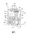
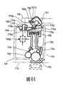
圖2係依據本發明的第一實施例之處理匣的剖面圖。Figure 2 is a cross-sectional view of the processing cartridge according to the first embodiment of the present invention.
圖3例示依據本發明的第一實施例之電子攝影影像形成設備的一般配置。FIG. 3 illustrates the general configuration of the electrophotographic image forming apparatus according to the first embodiment of the present invention.
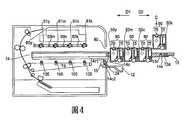
圖4例示依據本發明的第一實施例之處理匣的交換。Fig. 4 illustrates the exchange of the processing cassette according to the first embodiment of the present invention.
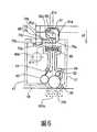
圖5係如於依據本發明的第一實施例之光敏滾筒的軸向所視之處理匣的剖面圖。5 is a cross-sectional view of the processing cartridge as viewed in the axial direction of the photosensitive drum according to the first embodiment of the present invention.
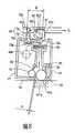
圖6係如於依據本發明的第一實施例之光敏滾筒的軸向所視之處理匣的剖面圖。6 is a cross-sectional view of the processing cartridge as viewed in the axial direction of the photosensitive drum according to the first embodiment of the present invention.
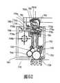
圖7係如於依據本發明的第一實施例之光敏滾筒的軸向所視之處理匣的剖面圖。Fig. 7 is a cross-sectional view of the processing cartridge as viewed in the axial direction of the photosensitive drum according to the first embodiment of the present invention.
圖8係如於依據本發明的第一實施例之光敏滾筒的軸向所視之處理匣的剖面圖。8 is a cross-sectional view of the processing cartridge as viewed in the axial direction of the photosensitive drum according to the first embodiment of the present invention.
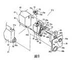
圖9係如自依據本發明的第一實施例的驅動側所視之處理匣的立體圖。9 is a perspective view of the processing cartridge as viewed from the driving side according to the first embodiment of the present invention.
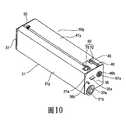
圖10係如自依據本發明的第一實施例的驅動側所視之處理匣的立體圖。Fig. 10 is a perspective view of the processing cartridge as viewed from the driving side according to the first embodiment of the present invention.
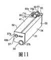
圖11係如自依據本發明的第一實施例的非驅動側所視之處理匣的立體圖。Fig. 11 is a perspective view of the processing cartridge as viewed from the non-driving side according to the first embodiment of the present invention.
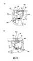
圖12係如自依據本發明的第一實施例的非驅動側所視之處理匣的立體圖。Fig. 12 is a perspective view of the processing cartridge as viewed from the non-driving side according to the first embodiment of the present invention.
圖13係如自依據本發明的第一實施例的非驅動側所視之處理匣的立體圖。Fig. 13 is a perspective view of the processing cartridge as viewed from the non-driving side according to the first embodiment of the present invention.
圖14係如自依據本發明的第一實施例的非驅動側所視之處理匣的立體圖。14 is a perspective view of the processing cartridge as viewed from the non-driving side according to the first embodiment of the present invention.
圖15係顯示依據本發明的第一實施例之處理匣的力接收裝置之立體圖。15 is a perspective view showing the force receiving device of the processing cartridge according to the first embodiment of the present invention.
圖16係顯示依據本發明的第一實施例之處理匣的力接收裝置之立體圖。Fig. 16 is a perspective view showing the force receiving device of the processing cartridge according to the first embodiment of the present invention.
圖17係顯示依據本發明的第一實施例之處理匣的力接收裝置之立體圖。FIG. 17 is a perspective view showing the force receiving device of the processing cartridge according to the first embodiment of the present invention.
圖18係顯示依據本發明的第一實施例之處理匣的力接收裝置之立體圖。18 is a perspective view showing the force receiving device of the processing cartridge according to the first embodiment of the present invention.
圖19係顯示依據本發明的第一實施例之處理匣的力接收裝置之立體圖。19 is a perspective view showing the force receiving device of the processing cartridge according to the first embodiment of the present invention.
圖20係顯示依據本發明的第一實施例之處理匣的力接收裝置之立體圖。20 is a perspective view showing the force receiving device of the processing cartridge according to the first embodiment of the present invention.
圖21係顯示依據本發明的第一實施例之處理匣的力接收裝置之立體圖。21 is a perspective view showing the force receiving device of the processing cartridge according to the first embodiment of the present invention.
圖22例示依據本發明的第一實施例之處理匣,其中第一力接收構件及第二力接收構件係藉由電子攝影影像形 成設備的第一力接收構件及第二力接收構件發生作用。Fig. 22 illustrates the processing cartridge according to the first embodiment of the present invention, in which the first force receiving member and the second force receiving member are operated by the first force receiving member and the second force receiving member of the electrophotographic image forming apparatus.
圖23係依據本發明的第一實施例之電子攝影影像形成設備的一般配置。FIG. 23 shows the general configuration of the electrophotographic image forming apparatus according to the first embodiment of the present invention.
圖24係依據本發明的第一實施例之電子攝影影像形成設備的一般配置。Fig. 24 is a general configuration of the electrophotographic image forming apparatus according to the first embodiment of the present invention.
圖25係依據本發明的第一實施例之電子攝影影像形成設備的一般配置。Fig. 25 is a general configuration of the electrophotographic image forming apparatus according to the first embodiment of the present invention.
圖26係依據本發明的第一實施例之電子攝影影像形成設備的一般配置。Fig. 26 shows the general configuration of the electrophotographic image forming apparatus according to the first embodiment of the present invention.
圖27例示依據本發明的第一實施例之第一施力構件的操作。Fig. 27 illustrates the operation of the first force applying member according to the first embodiment of the present invention.
圖28例示依據本發明的第一實施例之第二施力構件的操作。FIG. 28 illustrates the operation of the second force applying member according to the first embodiment of the present invention.
圖29係依據本發明的第一實施例之電子攝影影像形成設備的立體圖。Fig. 29 is a perspective view of the electrophotographic image forming apparatus according to the first embodiment of the present invention.
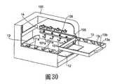
圖30係依據本發明的第一實施例之電子攝影影像形成設備的立體圖。FIG. 30 is a perspective view of the electrophotographic image forming apparatus according to the first embodiment of the present invention.
圖31例示依據本發明的第一實施例的之處理匣的交換。Fig. 31 illustrates the exchange of the processing cassette according to the first embodiment of the present invention.
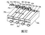
圖32例示依據本發明的第一實施例之處理匣的交換。Fig. 32 illustrates the exchange of the processing cassette according to the first embodiment of the present invention.
圖33係如於依據本發明的第一實施例之光敏滾筒的軸向所視之處理匣的剖面圖,例示處理匣的力接收構件的操作。FIG. 33 is a cross-sectional view of the processing cassette as viewed in the axial direction of the photosensitive drum according to the first embodiment of the present invention, illustrating the operation of the force receiving member of the processing cassette.
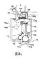
圖34係如於依據本發明的第一實施例之光敏滾筒的軸向所視之處理匣的剖面圖,例示處理匣的力接收構件的操作。Fig. 34 is a cross-sectional view of the processing cartridge as viewed in the axial direction of the photosensitive drum according to the first embodiment of the present invention, illustrating the operation of the force receiving member of the processing cartridge.
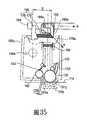
圖35係如於依據本發明的第一實施例之光敏滾筒的軸向所視之處理匣的剖面圖,例示處理匣的力接收構件的操作。35 is a cross-sectional view of the processing cartridge as viewed in the axial direction of the photosensitive drum according to the first embodiment of the present invention, illustrating the operation of the force receiving member of the processing cartridge.
圖36例示依據本發明的第一實施例之處理匣中的間距操作。Figure 36 illustrates the spacing operation in the processing cassette according to the first embodiment of the present invention.
圖37例示依據本發明的第一實施例之處理匣中的間距操作。Fig. 37 illustrates the spacing operation in the processing cassette according to the first embodiment of the present invention.
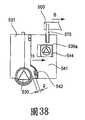
圖38例示依據本發明的第一實施例之處理匣中的間距操作。Figure 38 illustrates the spacing operation in the processing cassette according to the first embodiment of the present invention.
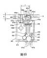
圖39係依據本發明的第二實施例之電子攝影影像形成設備的一般配置。Fig. 39 is a general configuration of an electrophotographic image forming apparatus according to the second embodiment of the present invention.
圖40係依據本發明的第二實施例之電子攝影影像形成設備的一般配置。Fig. 40 is a general configuration of an electrophotographic image forming apparatus according to the second embodiment of the present invention.
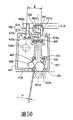
圖41係依據本發明的第二實施例之電子攝影影像形成設備的一般配置。Fig. 41 is a general configuration of an electrophotographic image forming apparatus according to the second embodiment of the present invention.
圖42例示依據本發明的第二實施例之電子攝影影像形成設備的第一施力操作構件的操作。FIG. 42 illustrates the operation of the first urging operation member of the electrophotographic image forming apparatus according to the second embodiment of the present invention.
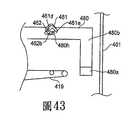
圖43係依據本發明的第二實施例之第一施力構件的操作例示。Fig. 43 is an example of the operation of the first force applying member according to the second embodiment of the present invention.
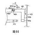
圖44係依據本發明的第二實施例之第一施力構件的操作例示。Fig. 44 is an example of the operation of the first force applying member according to the second embodiment of the present invention.
圖45係依據本發明的第二實施例之第一施力構件的操作例示。FIG. 45 is an example of the operation of the first force applying member according to the second embodiment of the present invention.
圖46係如於依據本發明的第二實施例之光敏滾筒的軸向所視之處理匣的剖面圖。Figure 46 is a cross-sectional view of the processing cartridge as viewed in the axial direction of the photosensitive drum according to the second embodiment of the present invention.
圖47例示如於依據本發明的第二實施例之光敏滾筒的軸向所視之處理匣的剖面圖,例示處理匣的力接收裝置。Fig. 47 illustrates a cross-sectional view of the processing cartridge as viewed in the axial direction of the photosensitive drum according to the second embodiment of the present invention, illustrating a force receiving device of the processing cartridge.
圖48例示如於依據本發明的第二實施例之光敏滾筒的軸向所視之處理匣的剖面圖,例示處理匣的力接收裝置。FIG. 48 illustrates a cross-sectional view of the processing cartridge as viewed in the axial direction of the photosensitive drum according to the second embodiment of the present invention, illustrating the force receiving device of the processing cartridge.
圖49例示如於依據本發明的第二實施例之光敏滾筒的軸向所視之處理匣的剖面圖,例示處理匣的力接收裝置。FIG. 49 illustrates a cross-sectional view of the processing cartridge as viewed in the axial direction of the photosensitive drum according to the second embodiment of the present invention, illustrating a force receiving device of the processing cartridge.
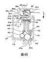
圖50例示如於依據本發明的第二實施例之光敏滾筒的軸向所視之處理匣的剖面圖,例示處理匣的力接收裝置。FIG. 50 illustrates a cross-sectional view of the processing cartridge as viewed in the axial direction of the photosensitive drum according to the second embodiment of the present invention, illustrating the force receiving device of the processing cartridge.
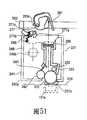
圖51係依據本發明的第三實施例之處理匣的剖面圖,例示處理匣的力接收構件的操作。FIG. 51 is a cross-sectional view of the processing cassette according to the third embodiment of the present invention, illustrating the operation of the force receiving member of the processing cassette.
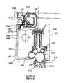
圖52係依據本發明的第三實施例之處理匣的剖面圖,例示處理匣的力接收構件的操作。FIG. 52 is a cross-sectional view of the processing cassette according to the third embodiment of the present invention, illustrating the operation of the force receiving member of the processing cassette.
圖53係依據本發明的第三實施例之處理匣的剖面圖,例示處理匣的力接收構件的操作。FIG. 53 is a cross-sectional view of the processing cassette according to the third embodiment of the present invention, illustrating the operation of the force receiving member of the processing cassette.
圖54係依據本發明的第三實施例之處理匣的剖面圖,例示處理匣的力接收構件的操作。Fig. 54 is a cross-sectional view of the processing cassette according to the third embodiment of the present invention, illustrating the operation of the force receiving member of the processing cassette.
圖55係如於依據本發明的第四實施例之光敏滾筒的軸向所視之處理匣的剖面圖,例示處理匣的力接收裝置。Fig. 55 is a cross-sectional view of the processing cartridge as viewed in the axial direction of the photosensitive drum according to the fourth embodiment of the present invention, illustrating the force receiving device of the processing cartridge.
圖56係如於依據本發明的第四實施例之光敏滾筒的軸向所視之處理匣的剖面圖,例示處理匣的力接收裝置。Fig. 56 is a cross-sectional view of the processing cartridge as viewed in the axial direction of the photosensitive drum according to the fourth embodiment of the present invention, illustrating a force receiving device of the processing cartridge.
圖57係如於依據本發明的第四實施例之光敏滾筒的軸向所視之處理匣的剖面圖,例示處理匣的力接收裝置。Fig. 57 is a cross-sectional view of the processing cartridge as viewed in the axial direction of the photosensitive drum according to the fourth embodiment of the present invention, illustrating the force receiving device of the processing cartridge.
圖58係如於依據本發明的第四實施例之光敏滾筒的軸向所視之處理匣的剖面圖,例示處理匣的力接收裝置。FIG. 58 is a cross-sectional view of the processing cartridge as viewed in the axial direction of the photosensitive drum according to the fourth embodiment of the present invention, illustrating the force receiving device of the processing cartridge.
圖59係依據本發明的第五實施例之處理匣的立體圖,如自驅動側所視。Fig. 59 is a perspective view of a processing cartridge according to a fifth embodiment of the present invention, as viewed from the driving side.
圖60係依據本發明的第五實施例之處理匣的立體圖,如自驅動側所視。Fig. 60 is a perspective view of a processing cartridge according to a fifth embodiment of the present invention, as viewed from the driving side.
圖61係依據本發明的第六實施例之處理匣的剖面圖。Figure 61 is a cross-sectional view of a processing cartridge according to a sixth embodiment of the present invention.
圖62係依據本發明的第六實施例之處理匣的剖面圖。Figure 62 is a cross-sectional view of a processing cartridge according to a sixth embodiment of the present invention.
圖63係依據本發明的第六實施例之處理匣的剖面圖。Figure 63 is a cross-sectional view of a processing cartridge according to a sixth embodiment of the present invention.
圖64係依據本發明的第六實施例之處理匣的剖面圖。Figure 64 is a cross-sectional view of a processing cartridge according to a sixth embodiment of the present invention.
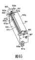
圖65係依據第七實施例之處理匣的立體圖,例示處理匣的力接收裝置。Fig. 65 is a perspective view of the processing cassette according to the seventh embodiment, illustrating the force receiving device of the processing cassette.
圖66係依據第七實施例之處理匣的立體圖,例示處理匣的力接收裝置。Fig. 66 is a perspective view of the processing cassette according to the seventh embodiment, illustrating the force receiving device of the processing cassette.
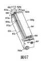
圖67係依據第七實施例之處理匣的立體圖,例示處理匣的力接收裝置。Fig. 67 is a perspective view of the processing cassette according to the seventh embodiment, illustrating the force receiving device of the processing cassette.
圖68係依據第七實施例之處理匣的立體圖,例示處理匣的力接收裝置。Fig. 68 is a perspective view of the processing cassette according to the seventh embodiment, illustrating the force receiving device of the processing cassette.
參照圖1-4,依據本發明的第一實施例之處理匣及電子攝影影像形成設備。Referring to FIGS. 1-4, a processing cartridge and an electrophotographic image forming apparatus according to a first embodiment of the present invention.
圖1顯示包括可拆卸地安裝的處理匣(匣)50y、50m、50c、50k之電子攝影影像形成設備(設備的主總成)100。匣50y、50m、50c、50k分別含有或容置黃色色料(顯影劑)、洋紅色色料(顯影劑)、青色色料(顯影劑)及黑色色料(顯影劑)。圖2係單獨的匣的剖面側視圖;圖3及4係自設備主總成100移除匣50y、50m、50c、50k的例示。FIG. 1 shows an electrophotographic image forming apparatus (main assembly of the apparatus) 100 including detachably installed processing cassettes (cassettes) 50y, 50m, 50c, and 50k. The
如圖1所示,設備主總成100中,電子攝影光敏滾筒(光敏滾筒)30y、30m、30c、30k係藉由雷射掃瞄器10曝露於依據影像信號所調變的雷射光束11,以使靜電潛像被形成在表面上。靜電潛像係在光敏滾筒30的各別表面上藉由顯影滾輪42顯影成色料影像(已顯影影像)。藉由施加電壓於傳輸滾輪18y、18m、18c、18k,形成在 光敏滾筒30y、30m、30c、30k上之各別顏色的色料影像係相繼地轉移至傳輸皮帶19上。之後,形成在傳輸皮帶19上之色料影像係由傳輸滾輪3來轉移至由進給滾輪1(進給機構)所進給的記錄材料P上。之後,記錄材料P係進給至包括驅動滾輪之定影單元6及含有加熱器的定影滾輪。在此,藉由施加熱及壓力在記錄材料P上,轉移至記錄材料P之色料影像被定影。之後,具有定影其上的色料影像之記錄材料係藉由一對排放滾輪7而排放至排放部9。As shown in Fig. 1, in the
參照圖1、2、5及22、29、30,將說明此實施例的匣50y、50m、50c、50k。因為匣50y、50m、50c、50k除了含於其中的色料的顏色相互不同之外全都相同,以下僅關於匣50y作說明。With reference to Figures 1, 2, 5 and 22, 29, 30, the
匣50y包括光敏滾筒30、及可作用在光敏滾筒30上之處理機構。處理機構包括作用如用於充電光敏滾筒30的充電機構之充電滾輪32、作用如用於使形成在光敏滾筒30上的潛像顯影之顯影機構、及/或作用如用於移除留在光敏滾筒30的表面上的剩餘色料的清潔機構之刮片33。匣50y包含滾筒單元31及顯影單元41。The
如圖2、10所示,滾筒單元31含有光敏滾筒30、充 電滾輪32、清潔機構33、剩餘色料容置部35、滾筒架34及覆蓋構件36、37。如圖9所示,光敏滾筒30的一縱向端係由覆蓋構件36的支承部36b而可旋轉地支承。如圖11至14所示,光敏滾筒30的另一縱向端係由覆蓋構件37的支承部37b而可旋轉地支承。覆蓋構件36、37係在滾筒架34的對置縱向端而固定至滾筒架34。如圖9、10所示,光敏滾筒30的一縱向端設有用於接收旋轉光敏滾筒30的驅動力之耦合構件30a。當匣50y安裝至設備的主總成100時,耦合構件30a係與圖4、30所示的第一主總成耦合構件105嚙合。光敏滾筒30係藉由自設於設備主總成100的驅動馬達(未顯示)轉移至耦合構件30a之驅動力而旋轉於如圖2所示之箭頭u的方向。充電滾輪32係支承在滾筒架34上,且係藉由與充電滾輪32接觸之光敏滾筒30所旋轉。清潔機構33係藉由滾筒架34所支承,且與光敏滾筒30的周圍表面接觸。覆蓋構件36、37設有用於旋轉(運動)支承顯影單元41之支承孔部36a、37a。As shown in Figs. 2 and 10, the
如圖2所示,顯影單元41含有顯影滾輪42、顯影刮片43、顯影裝置架48、軸承單元45及覆蓋構件46。顯影裝置架48包含用於容置待供應至顯影滾輪42的色料之色料容置部49、及用於規制顯影滾輪42的周圍表面的色料層厚度之顯影刮片43。如圖9所示,軸承單元45係固 定至顯影裝置架48的一縱向端側,且在其末端旋轉地支承具有顯影滾輪齒輪69之顯影滾輪42。軸承單元45設有耦合構件67、及用於自耦合構件67傳輸驅動力至顯影滾輪齒輪69之惰輪68。覆蓋構件46係固定至軸承單元45的縱向外側以覆蓋耦合構件67及惰輪68。覆蓋構件46設有突起超過覆蓋構件46的表面之圓柱部46b。耦合構件67係經由圓柱部46b的內側開口而曝露。在此,當匣50y係安裝至設備主總成100時,耦合構件67係與圖30所示的第二主總成耦合構件106嚙合以自設於設備主總成100的驅動馬達(未顯示)來傳輸驅動力。As shown in FIG. 2, the developing
如圖9、11至14所示,當顯影單元41及滾筒單元31相互組裝時,圓柱部46b的外圓周係在一端側與支承孔部36a嚙合,且自顯影裝置架48突出設置之突出部48b係在另一端側與支承孔部37a嚙合。藉由如此作,顯影單元41係相對於滾筒單元31而旋轉支承的。如圖2所示,顯影單元41係藉由推動彈簧95(彈性構件)所推動使得顯影滾輪42繞著圓柱部46b及突出部48b旋轉以接觸到光敏滾筒30。更特別地,顯影單元41係由推動彈簧95的推力而推動於箭頭G的方向使得顯影單元41接收圓柱部46b及突出部48b周圍之力矩H。藉此,顯影滾輪42可以預定壓力接觸到光敏滾筒30。顯影單元41在此時的位置係“接觸位置”。As shown in Figures 9, 11 to 14, when the developing
如圖10所示,此實施例的推動彈簧95係設在相對於設有光敏滾筒30的耦合構件30a及顯影滾輪齒輪69的耦合構件67的一縱向端之端上。因為此種結構,設在該一縱向端上之力接收裝置90(以下將後述)的第一力接收構件75自第一施力構件61接收之力g(圖6)產生圓柱部46b周圍之力矩於顯影單元41。換言之,在該一縱向端,因此產生之力矩h係有效地以預定壓力將顯影滾輪42推動至光敏滾筒30。在另一端,推動彈簧95作用來以預定壓力將顯影滾輪42推至光敏滾筒30。As shown in FIG. 10, the
如圖2所示,匣50y設有力接收裝置90,用於實施設備主總成100中之顯影滾輪42與光敏滾筒30間的接觸及隔開。如圖9、15及19所示,力接收裝置90包括第一力接收構件75、第二力接收構件70及彈簧73(推動機構)。As shown in FIG. 2, the
如圖9所示,第一力接收構件75係藉由使第一力接收構件的嚙合部75d與軸承單元45的引導部45b嚙合而安裝至軸承單元45。另一方面,第二力接收構件70係藉由使第二力接收構件70的軸70a與軸承單元45的引導部45a嚙合而安裝至軸承單元45。因此具有第一力接收構件75及第二力接收構件70之軸承單元45係固定至顯影裝置架48,然後如圖10所示,覆蓋構件46被固定以於軸承單元45的顯影滾輪42的軸向自外側覆蓋軸承單元 45。於匣50y安裝至設備主總成100的狀態中,第一力接收構件75及第二力接收構件70係配置在匣50y上方。As shown in FIG. 9, the first
以下將詳細說明力接收裝置90的操作。The operation of the
現將作關於匣托架13的說明,匣托架13係抽取構件。A description will now be made about the
如圖4所示,匣托架13係沿著大致平行於設備主總成100直線(D1、D2方向)可運動(插入及抽出)。更特別地,匣托架13可運動在圖1所示的設備主總成100的安裝位置及圖4所示的設備主總成100外側的抽出位置之間。於匣托架13位在抽出位置之狀態中,匣50y、50m、50c、50k係如圖4所示的由操作者大致垂直(箭頭C)安裝在匣托架13上。匣50y、50m、50c、50k係相互平行配置,以使因此縱向(光敏滾筒30及顯影滾輪42的軸向)係大致垂直至匣托架13的運動方向。匣50y、50m、50c、50k係在支承在匣托架13的同時進入設備主總成100。同時,匣50y、50m、50c、50k係在中間傳輸皮帶19及光敏滾筒30之間保持一距離(間隙f2)(圖5)的情況下運動。中間傳輸皮帶19設置在匣50y、50m、50c、50k的下方。當匣托架13係定位在安裝位置時,匣50y、50m、50c、50k係由設於影像形成設備100的主總成的定位部101a而定位在適當位置。以下將詳細說明定位操作。因此,使用者可藉由使匣托架13進入及 關閉門12而將匣50y、50m、50c、50k確定地裝入設備主總成100。因此,使用者將匣50y、50m、50c、50k單獨裝入設備主總成100的結構之操作性被改善。As shown in Fig. 4, the
參照圖23至25及36至38,將說明匣托架13的操作。Referring to Figures 23 to 25 and 36 to 38, the operation of the
在此,為了簡化匣托架13的操作的說明,匣被省略。Here, in order to simplify the description of the operation of the
匣托架13係相對於托架固持構件14可抽取地支承。托架固持構件14係可與門12(開啟及關閉構件)的運動相關地運動。門12設在設備主總成100上,且可繞著旋轉中心12a而旋轉。The
當自設備主總成100取出匣時,門12自關閉位置移至開啟位置。以門12的運動,設在門12上之嚙合部15繞著旋轉中心12a以順時鐘運動。然後,如圖24所示,嚙合部15自下端14c2朝向上端14c1運動於設於托架固持構件14之細長孔14c。與此操作一起,嚙合部15運動托架固持構件14於方向z1。此時,如圖25所示,自托架固持構件14突出之凸部14d1、14d2係藉由設於設備主總成100之引導狹縫或槽部107所引導。如圖26所示,引導槽部包括水平部107a1、自水平部107a1延續且向上傾斜之傾斜部107a2、及自傾斜部107a2延續之水平部107a3。因此,如圖24所示,當門12移至開啟位置時,凸部14d1、14d2係沿著水平部107a1、傾斜部107a2及水平部107a3的順序而引導。因此,托架固持構件14運動 於z1的方向且離開傳輸皮帶19之箭頭y1的方向。於此狀態中,如圖25所示,匣托架13可經由開口80朝向設備主總成100的外側抽出於箭頭D2的方向。圖30係此狀態的部份剖開立體圖。When the cassette is removed from the
現將說明將匣安裝入設備主總成100的例子。於門12位在如圖25所示的開啟位置之狀態中,匣托架13係經由開口80於箭頭D1的方向而進入設備主總成100。之後,如圖23所示,門12移至關閉位置。以門12的運動,設在門12上之嚙合部15繞著旋轉中心12a以逆時鐘運動。然後,如圖23所示,嚙合部15朝向細長孔14c的下端14c2沿著設於托架固持構件14的細長孔14c而運動。與此操作一起,嚙合部15運動托架固持構件14於方向z2。因此,如圖23所示,當門12移至關閉位置時,凸部14d1、14d2係藉由水平部107a3、傾斜部107a2及水平部107a1的順序而引導。因此,托架固持構件14運動於方向z2,且朝向傳輸皮帶19運動於箭頭y2的方向。An example of installing the cartridge into the
參照圖5、15及圖19、27、29、30,將說明匣50y、50m、50c、50k相對於設備主總成100的位置。5, 15 and FIGS. 19, 27, 29, 30, the positions of the
如圖30所示,設有用於定位匣50y、50m、50c、50k於設備主總成100之定位部101a。定位部101a被提供給各別匣50y、50m、50c、50k相對於縱向而插置在傳輸皮帶19上。如圖27(a)及27(b)所示,第一施力構件 61係在托架固持構件14上方的位置藉由支承孔61d嚙合的設備主總成100的支承軸55所旋轉及支承。As shown in Fig. 30, a
如圖27(a)及27(b)所示,第一施力構件61隨著門12自開啟位置至關閉位置的運動而運動。如圖20所示,設在第一施力構件61上之突出部61f推動設在滾筒架34的上表面部上之凸部31a。藉此,匣50y被推動於箭頭P的方向(圖19),使得設在滾筒單元31y上之待定位部31b(圖7)鄰接於設於設備主總成100之定位部101a,匣50y係藉由定位部101a定位於適當位置(圖6)。相同操作被實施在相鄰的對置縱向端。且,相同操作被實施於其它匣50m、50c、50k。As shown in FIGS. 27(a) and 27(b), the first
現將說明與門12的運動相關之第一施力構件61的運動機構。第一施力構件61係與門12的運動相關地與連接構件62嚙合。如圖15至19所示,連接構件62包括與支承軸55嚙合之支承孔62c、與突出部61f嚙合之孔62a、及與設於托架固持構件14之細長孔14b(圖27(b))嚙合之支承銷62b。如圖27所示,藉由門12的運動自開啟位置至關閉位置,托架固持構件14運動於箭頭y2的方向(圖27)。藉此,與細長孔14b嚙合之支承銷62b亦接收箭頭y2方向的力。因此,連接構件62繞著支承孔62c旋轉於箭頭Z的方向(圖27)。如圖19所示,在第一施力構件61及連接構件62之間,設有彈簧66。彈簧66係由支承軸55所支承,且與設在連接構件62上的凸部62e及設在第一施力構件61上的突出部61f接觸。藉由彈簧 66的推力,突出部61f推動設在滾筒架34上之凸部31a於箭頭P的方向,以定位匣50y、50m、50c、50k至設備主總成100的定位部101a。The movement mechanism of the first
如圖21所示,凸部31a可由彈簧66直接推動。因此,連接構件62與門12的運動相關之結構係和圖15至圖20相同的。當門12位在開啟位置時,彈簧66的一端66b係與設在連接構件62上的鉤部62e嚙合,而彈簧66的另一端66a係與設在連接構件62上之凸部62f嚙合。藉著門12自開啟位置移至關閉位置,另一端66a變成離開凸部62f,且直接推動凸部31a來定位匣50y、50m、50c、50k至設備主總成100的定位部101a。As shown in FIG. 21, the
回到圖5至8及圖11至19,將說明用於操作設在匣50y上的力接收裝置90之機構。圖5至8係如於光敏滾筒30的軸向所視之匣的剖面圖,而圖11至14係如自匣50y的非驅動側所視之立體圖。圖5所示的狀態對應於圖11所示的狀態及圖15所示的狀態。圖6所示的狀態對應於圖12所示的狀態及圖16所示的狀態。圖7所示的狀態對應於圖13所示的狀態,而圖8的狀態對應至圖14的狀態。Returning to FIGS. 5 to 8 and FIGS. 11 to 19, the mechanism for operating the
如以上所述,以門12自開啟位置的關閉操作,第一施力構件61繞著支承軸55自圖5、11及15的狀態移至圖6、12、16的狀態。此時,第一施力構件61不僅相對 於設備主總成100而定位匣50y,而且還作用在匣50y的第一力接收構件75上。更特別地,第一施力構件61的推動部61e鄰接第一力接收構件75的第一推動部。之後,第一力接收構件75推動設於第二力接收構件70之凸輪表面70c(第三推動部),第二力接收構件70係藉由凸輪表面70c繞著軸70a旋轉。然後,第二力接收構件70係自如圖5、11、15所示的待機位置移至匣50y的顯影單元41的外側,亦即,離開顯影單元41的圓柱部46b。以圖21所示的結構,自連接構件62突出之突出部62g作用如第一施力構件61。As described above, with the closing operation of the
參照圖28,將說明第二施力構件60的操作。28, the operation of the second
來自馬達110(驅動源)之驅動力設於設備主總成100係藉由齒輪111傳輸至齒輪112。接收驅動力之齒輪112旋轉於箭頭L的方向,以使與齒輪112整體設置之凸輪部112a旋轉於箭頭L的方向。凸輪部112a係與設在第二施力構件60上之運動力接收部60b嚙合。因此,隨著凸輪部112a的旋轉,第二施力構件60運動於箭頭E或B的方向。The driving force from the motor 110 (drive source) is provided in the
圖28於(a)例示第二施力構件60運動於箭頭E的方向且顯影滾輪42及光敏滾筒30仍相互接觸(圖7)之例子。圖28於(b)例示第二施力構件60運動於箭頭B的方向且第二力接收構件70接收來自嚙合肋部60y的力之例子。藉此,顯影單元41係繞著旋轉軸46b旋轉(運動),使得顯影滾輪42及光敏滾筒30相互隔開。顯影單 元41在此時的位置係隔開位置。Fig. 28 illustrates in (a) an example in which the second urging
如圖15所示,第二施力構件60設有用於允許支承軸55的運動之細長孔部60c,第一施力構件61係可旋轉地設置在支承軸55上。因此,甚至當第二施力構件60運動於箭頭B的方向(圖8)或箭頭E的方向(圖7),第二施力構件60可運動而不會被第一施力構件61防礙。相似於第一施力構件61,第二施力構件60係面向匣的運動路徑而設置,以便在匣托架13上定位於進入設備主總成100的匣50y、50m、50c、50k上方。於匣50y、50m、50c、50k進入設備主總成100的前進步驟中,第二力接收構件70係保持在準備位置(圖15)。因此,第一施力構件61及第二施力構件60只要不相互干擾可非常接近至匣50y、50m、50c、50k,使得浪費空間可被移除。因此,設備主總成100可相對於匣50y的垂直方向及縱向(光敏滾筒30的軸向)而縮小。As shown in FIG. 15, the second urging
以下將詳細說明該操作。The operation will be described in detail below.
現將說明自匣50y、50m、50c、50k對設備主總成100的安裝至顯影滾輪42從光敏滾筒30的分離之系列操作。A series of operations from the installation of the
如圖4所示,匣50y、50m、50c、50k係自上方安裝至匣托架13,匣托架13係於箭頭C的方向而抽出至抽出 位置。As shown in Fig. 4, the
由運動匣托架13於箭頭D1的方向,匣50y、50m、50c、50k係經由開口80通過進入設備主總成100。因此,於此實施例中,匣50y、50m、50c、50k係於大致垂直至光敏滾筒30的軸向之方向而插至設備主總成100。From the moving
如圖31、32所示,匣50y係安裝在匣托架13上相對於插入或進入方向之最下游位置。匣50y自上游側朝向第一施力構件61k、61c、61m及第二施力構件60的嚙合肋部60k、60c、60m下方的下游側而前進,嚙合肋部60k、60c、60m係可作用在匣50m、50c、50k。As shown in FIGS. 31 and 32, the
匣50m係安裝在始於匣托架13上相對於進入方向的下游側之第二位置。匣50m自上游側朝向第一施力構件61k、61c及第二施力構件60的嚙合肋部60k、60c下方的下游側而前進,嚙合肋部60k、60c係作用在匣50c、50k。The
匣50c係安裝在始於匣托架13上相對於進入方向的下游側之第三位置。匣50c自上游側朝向第一施力構件61k及第二施力構件60的嚙合肋部60k下方的下游側而通過,嚙合肋部60k係作用在匣50k。The
匣托架13相對於進入方向之最上游匣50k自上游側朝向下游側進入,使得其第二力接收構件70通過作用在匣50k上之第一施力構件61下方。The most
至於匣50y、50m、50c,第二力接收構件70自上游側朝向下游側而通過第一施力構件61k下方係相同。As for the
亦即,當處理匣隨著第二力接收構件70的突出而插入時,第一施力構件61及第二施力構件60必須位在上部以避免第二力接收構件70防礙到第一施力構件61及第二施力構件60。然而,如果第二力接收構件70在準備位置,第一施力構件61及第二施力構件60可被配置接近至匣50y、50m、50c、50k而無需考慮到第二力接收構件70的突出程度。因此,設備主總成100可相對於垂直方向而縮小。再者,如圖31、32所示,力接收裝置90、第一施力構件61及第二施力構件60的位置致使力接收裝置90於滾筒軸向與第一施力構件61及第二施力構件60重疊,且因此,匣可相對於其縱向而縮小。That is, when the processing cartridge is inserted with the protrusion of the second
當匣托架13插入設備主總成100時,間隙f1被保持在第二施力構件60及力接收裝置90之間,如圖5所示。而且,間隙f2被保持在光敏滾筒30及傳輸皮帶19之間。因此,匣50y、50m、50c、50k可進入而不會防礙到設備主總成100。When the
之後,如圖23所示,由運動門12至關閉位置,托架固持構件14運動於趨近於傳輸皮帶19的方向(箭頭y2)。箭頭y2的方向之運動距離的垂直分量係f2。因此,如圖6所示,匣50y、50m、50c、50k亦運動使得光敏滾筒30的表面被致使接觸到傳輸皮帶19的表面。於此狀態中,力接收裝置90及第二施力構件60間之間隙f1擴大為f1+f2。After that, as shown in FIG. 23, from the moving
再者,由運動門12至關閉位置,第一施力構件61被 運動以使設在滾筒架34的上表面部上之凸部31a被突出部61f推動。藉此,如圖6所示,匣50y、50m、50c、50k的定位部31b係鄰接至設於設備主總成100之各別定位部101a,使得匣50y、50m、50c、50k定位在設備主總成100。Furthermore, from the moving
設備主總成100中,藉由使圖10所示設在覆蓋構件36上的軸36d與設在匣托架13上的旋轉防止部13a嚙合,匣50y、50m、50c、50k被防止運動於箭頭a的方向(圖1)。In the
第一施力構件61的推動部61e接觸且推動定位在第一位置(圖15)之第一力接收構件75的被推動部75a(圖15)。之後,第一力接收構件75被運動於箭頭r的方向以定位在第二位置(圖16)。The pushing
在第二位置,推動部75b推動圖15所示的第二力接收構件70的凸輪表面70c。因此,第二力接收構件70繞著軸70a的軸自準備位置旋轉至匣50y、50m、50c、50k的顯影單元41外側之位置,亦即,於離開顯影單元41的旋轉軸46b之方向中。In the second position, the pushing
然而,此時,第二力接收構件70的上表面防礙到位在原始位置之第二施力構件60的嚙合肋部60y的下表面,藉此,第二力接收構件70的運動係由嚙合肋部60y所規制(圖6、12)。第二力接收構件70此時的位置稱為規制位置。However, at this time, the upper surface of the second
在此,由於以下理由,此位置成為原始位置:在匣 50y、50m、50c、50k被安裝至設備主總成100之後,該狀態係如圖8所示直到影像形成操作被實施。更特別地,第二施力構件60已被運動於箭頭B的方向,使得嚙合肋部60y推動第二力接收構件70。於此狀態中,光敏滾筒30及顯影滾輪42係相互隔開。於圖8的狀態中,匣50y、50m、50c、50k係自設備主總成100可拆卸地。之後,當匣50y、50m、50c、50k再次安裝至設備主總成100時,第二施力構件60位在圖8所示的位置,且因此,當第二力接收構件70自準備位置運動時,第二力接收構件70接觸到肋部60y。Here, this position becomes the original position due to the following reason: after the
如圖8所示,由第一力接收構件75自第一施力構件61所接收之力的方向(箭頭J)係大致相反於由第二力接收構件70自第二施力構件60所接收之力的方向。接收來自第二施力構件60的力之第二力接收構件70的表面面對匣50y、50m、50c、50k進入設備主總成100的方向。藉由選擇接收力的方向,當第二力接收構件70接收來自第二施力構件60之力時,顯影單元41可確定地相對於滾筒單元31有效率地運動。更者,光敏滾筒30及顯影滾輪42隔開之狀態可被穩定地保持。As shown in FIG. 8, the direction (arrow J) of the force received by the first
然而,甚至當第二力接收構件70的運動被嚙合肋部60y所限制時,包括第二施力構件60及第二力接收構件70之力接收裝置90未受損。如圖22(a)因為第二力接收構件70的運動被規制,用於推動凸輪表面70c之推動部75b的運動亦被規制。即使第一施力構件61的推動部 61e進一步推動被推動部75a,以拱形設在第一力接收構件75上之彈性部75c彎曲(彈性變形)。因此,即使第二力接收構件70的運動被規制,力接收裝置90未受損。However, even when the movement of the second
且,當第二施力構件60自圖6、12的位置運動於如圖7、13所示的箭頭E的方向時,第二力接收構件70運動在匣50y的外面以進入嚙合肋部60y的運動路徑。第二施力構件60的位置在此時稱為突出位置。因此,當第二施力構件60在突出位置時,第二施力構件60突出超過上述準備位置。第二力接收構件70在突出位置的突出程度大於間隙f1+f2以便與第二施力構件60嚙合。在匣50y、50m、50c、50k裝至設備主總成100之後,第二施力構件60的操作在影像形成之前被實施。And, when the second
然後,如圖8、14所示,第二施力構件60運動於箭頭B的方向,使得側表面70b(亦即,進入運動路徑之第二力接收構件70的第二推動部)接收來自嚙合肋部60y之力。因此,顯影單元41繞著旋轉軸46b而旋轉(運動),使得顯影滾輪42自光敏滾筒30隔開達間隙α。第二力接收構件70於突出位置接收來自第二施力構件60之力。因此,相較於第二力接收構件朝向處理匣運動且與顯影單元嚙合以實施顯影裝置間距之結構,距顯影單元41的旋轉軸46b之距離可被作大。因此,使顯影滾輪42與光敏滾筒30隔開所需之驅動力矩可被作小。Then, as shown in FIGS. 8 and 14, the second
再者,藉由第二施力構件60的運動於箭頭B的方向,第一施力構件61推動第一力接收構件75之位置及第 二力接收構件70接收來自嚙合肋部60y的力之位置相對於水平方向而改變。換言之,圖7所示之距離I及圖8所示的距離II間之關係係距離I>距離II。設在第一力接收構件75上之彈性部75c可適應之距離的變化。如圖22(a)所示,彈性部75c具有撓性拱形架構。在彈性部75c內,設有彈簧76(其為彈係構件)。彈簧76防止彈性部75c彎曲過度,且作用來恢復彎曲的彈性部75c。彈性部75c的拱形架構不是必然的,且彈性構件可以是簡單彈性構件。Furthermore, by the movement of the second
為了實施影像形成操作,顯影滾輪42係由運動第二施力構件60於箭頭E的方向而接觸到光敏滾筒30。藉此,如圖7、13所示,第二力接收構件70被致使成為未接收來自嚙合肋部60y的力的狀態。因此,由設在顯影單元41及滾筒單元31間之彈簧95的推力,顯影滾輪42及光敏滾筒30相互接觸使得匣50y、50m、50c、50k能夠形成影像。於此時,在顯影滾輪42接觸到光敏滾筒30之前,光敏滾筒30旋轉,以及顯影滾輪42亦接收來自設備主總成100之驅動力且旋轉。這是藉由設置與圓柱部46b同軸之耦合部67a所容置,使得即使顯影單元41繞著圓柱部46b而運動,耦合部67a的位置不會改變。因此,光敏滾筒30及顯影滾輪42在相互接觸之前被旋轉。因此,當顯影滾輪42被致使與光敏滾筒30接觸時,光敏滾筒30及顯影滾輪42的周圍表面間之速度差可被作小,且因此,光敏滾筒30及顯影滾輪42的磨耗可被降低。當影像 形成被完成時,顯影滾輪42及光敏滾筒30係由運動第二施力構件60於箭頭B的方向而相互隔開,如先前所述。在間隔之後,顯影滾輪42及光敏滾筒30的旋轉被停止。因此,光敏滾筒30及顯影滾輪42的周圍表面間之速度差被降低,且因此,光敏滾筒30及顯影滾輪42的磨耗可被降低。因此,影像品質可被改善。In order to perform the image forming operation, the developing
彈性部可以圖33、34、35所示的結構所取代。在此,力接收裝置190包含:第一力接收構件179及第二力接收構件178。如圖34、35所示,第一施力構件165設有滑動部165a(傾斜表面),而第一力接收構件179設有滑動部179a(傾斜表面)。圖33顯示在第一施力構件165運動之前之狀態。圖34顯示第二力接收構件178藉由第一施力構件165運動來鄰接第一力接收構件179自匣150y突出之狀態。圖35顯示在第二施力構件164運動於箭頭E的方向之狀態。The elastic part may be replaced by the structure shown in FIGS. 33, 34, and 35. Here, the
滑動部179a及滑動部165a間之可滑動性與第一力接收構件179於圖35所示的箭頭F的方向的可運動性允許圖34、35所示的第一力接收構件179及第二力接收構件178間之距離I至距離II的變化。The slidability between the sliding
在使用於此實施例的說明之匣50y中,顯影單元41相對於滾筒單元31係可旋轉以使顯影滾輪42及光敏滾筒30相互接觸及隔開。然而,圖36顯示替代性結構,其中待引導部544具有方形柱架構的形式,且滾筒單元531設有可與待引導部544嚙合之細長孔536a,其中顯影單元 541相對於滾筒單元531係可滑動地。In the
更特別,如圖37所示,當第二施力構件560未作用在第二力接收構件570時,顯影滾輪542由推動彈簧(未顯示)(彈性構件)所推動以使顯影滾輪542接觸至光敏滾筒。然後,如圖38所示,第二施力構件560運動於箭頭B的方向以作用在第二力接收構件570上。藉此,顯影單元541滑動於相對至滾筒單元531的方向,使得顯影滾輪542及光敏滾筒530被隔開達間隙g。相似於第一實施例,力接收裝置590包括第一力接收構件575及第二力接收構件570。More specifically, as shown in FIG. 37, when the
現將說明自設備主總成100取出匣50y、50m、50c、50k之操作。The operation of removing the
隨著門12自關閉位置至開啟位置的運動,第一施力構件61自圖6、12的位置旋轉至圖5、11的位置。藉此,第一力接收構件75自第一施力構件61的推力而釋放,使得第一力接收構件75自圖6、12所示的狀態移至圖5、11所示的狀態。更特別地,第二力接收構件70變成不受第一力接收構件75的推動部75b的約束。如圖5所示,第二力接收構件70亦於箭頭A的方向藉由圖19所示的彈簧73的力繞著軸70a而回到準備位置(非操作位置)。As the
隨著門12自關閉位置至開啟位置的運動,托架固持構件14離開傳輸皮帶19而升高如圖3、4所示。藉此,匣50y、50m、50c、50k被釋放,且因此,光敏滾筒30與 傳輸皮帶19分開。As the
如前所述,用於運動顯影單元41之第二力接收構件70係配置以使當匣50y、50m、50c、50k裝至設備主總成100及門12運動至關閉位置時,第二力接收構件70自顯影單元41向外突起。因此,匣50y、50m、50c、50k可被縮小。再者,因為安裝係當第二力接收構件70位在準備位置時被實施的,匣50y、50m、50c、50k的運動所需之設備主總成100中的空間可以是小。換言之,開口80的尺寸可以是小的,且第一施力構件61及第二施力構件60可以是接近匣50y、50m、50c、50k。因此,設備主總成100的尺寸相對於垂直方向可被減小。再者,如於設備主總成100的垂直方向所視,如圖31、32所示,力接收裝置90係相對於滾筒軸向與第一施力構件61及第二施力構件60重疊,且因此,匣相對於縱向可被縮小。As mentioned above, the second
當匣50y、50m、50c、50k被使用者操控時或當它們被運送時,第二力接收構件70可被放置在準備位置,且因此,第二力接收構件70不易受損。When the
於第一實施例中,匣50y、50m、50c、50k係於大致垂直至光敏滾筒30的軸向之方向中而安裝至設備主總成100。於第二實施例中,匣450y、450m、450c、450k係於大致平行於電子攝影光敏滾筒(光敏滾筒)430的軸向之方向中而安裝至電子攝影影像設備(設備的主總成)的主 總成401。In the first embodiment, the
如圖39、41所示,設備主總成401於大致平行於光敏滾筒430的軸向(縱向)之方向(箭頭K)中裝有匣450y、450m、450c、450k。於此實施例,匣450y、450m、450c、450k係於箭頭K的方向裝至設於設備主總成401之安裝構件480。匣450y、450m、450c、450k分別容置黃色、洋紅色、青色及黑色色料顆粒(顯影劑)。As shown in Figures 39 and 41, the
匣450y、450m、450c、450k各設有具有第一力接收構件475及第二力接收構件470之力接收裝置490。在設備主總成401的後側相對於匣進入方向,設有第一施力構件461及可分別作用在第一力接收構件475及第二力接收構件470上之第二施力構件460。如圖42所示,設備主總成100設有用於允許匣450y、450m、450c、450k進入設備主總成100之開口408及可運動在關閉開口408的關閉位置及開啟開口408之開啟位置之間的門412。門412係可繞著旋轉軸412a而旋轉。如圖45所示,安裝構件480整體包括分別用於固持匣450y、450m、450c、450k之固持部480c用於運動第一施力構件461之操作構件480b、及用於相互連接操作構件480b及門412之連接部480a。如圖42所示,連接部480a及門412係由設於連接部480a之細長孔480g及設在門412上之凸部412b間之嚙合而相互連接。The
因此,隨著門412於箭頭m的方向自開啟位置至關閉位置的運動,設在連接部480a上之凸部480d、480e沿著設於設備主總成401之引導槽部401a、401b而運動如圖42所示。因此,與操作構件480b整合之固持部480c運動於箭頭n的方向。因此,支承在固持部480c上之匣450y、450m、450c、450k的光敏滾筒430係自如圖47所示與傳輸皮帶419隔開之位置移至如圖48所示接觸到傳輸皮帶419之位置。同時,設在滾筒單元431上之待定位部431b係鄰接至設於設備主總成401之定位部401a,匣450y、450m、450c、450k係由定位部401a正確地定位。Therefore, as the
藉由使設在覆蓋構件436上的軸436d與設於設備主總成401的旋轉防止部485a嚙合,匣450y、450m、450c、450k的每一者於設備主總成401被防止運動於圖39中的箭頭a的方向。By engaging the shaft 436d provided on the covering member 436 with the
當自設備主總成401拆卸匣450y、450m、450c、450k時,該等操作與安裝操作相反。When the
參照圖40至45,將說明第一施力構件461的操作。相似於第一實施例,第一施力構件461係與操作構件480b的操作相關地與連接構件462嚙合。連接構件462的結構係相同如第一實施例。圖40及42(a)與43顯示門412位在開啟位置及操作構件480b取得上位置之狀態。圖41及42(b)與44顯示門412位於關閉位置之狀 態。當門412被關閉時,操作構件480b向下運動時(於箭頭n的方向)。如圖43、44所示,設在連接構件462上之凸部462b係與設於安裝構件480的細長孔480h嚙合。因此,隨著操作構件480b的運動,連接構件462繞著旋轉中心461d而旋轉於箭頭Q的方向。相似於第一實施例,第一施力構件461隨著連接構件462的旋轉而旋轉。當門412自關閉位置移至開啟位置時,該等操作係與上述操作相反。其它操作係相同如第一實施例。40 to 45, the operation of the first
第二施力構件460的操作係相同如第一實施例。The operation system of the second
現將說明此實施例的處理匣的結構。匣450y、450m、450c、450k的結構係相同,且因此,將參照圖46說明匣450y。The structure of the process cartridge of this embodiment will now be explained. The structures of the
匣450y包括光敏滾筒430、及可作用在光敏滾筒430上之處理機構。處理機構包括作用如用於充電光敏滾筒430的充電機構之充電滾輪432、作用如用於顯影形成在光敏滾筒430上的潛像顯影的顯影機構之顯影滾輪442、及/或作用如用於移除留在光敏滾筒430的表面上的剩餘色料的清潔機構之刮片433。匣450y包含滾筒單元431及顯影單元441。The
滾筒單元431及顯影單元441的結構與滾筒單元431及顯影單元441間的連接結構係相同如第一實施例。The structure of the
相似於第一實施例,如圖47所示,匣450y包括用於使顯影滾輪442與光敏滾筒430相互接觸及相互隔開之力接收裝置490。其詳細結構係相同如圖9及15-19。如圖47所示,此實施例的力接收裝置490包含第一力接收構件475、第二力接收構件470及彈簧(亦即,推動機構(未顯示))。Similar to the first embodiment, as shown in FIG. 47, the
圖49顯示在第二施力構件460自顯影滾輪442及光敏滾筒430仍相互接觸的原始位置(圖48)運動於箭頭E的方向之後的狀態。圖50顯示在第二施力構件460運動於箭頭B的方向之後之狀態,其中顯影滾輪442及光敏滾筒430相互隔開。相似於第一實施例,第二施力構件460設有用於避免第一施力構件461的旋轉軸461d之細長孔部460c。即使當第二施力構件460運動於箭頭E或箭頭B的方向,第二施力構件460可運動而不會干擾到第一施力構件461。FIG. 49 shows the state after the
如圖39、40所示,第一施力構件461及第二施力構件460係設置在進入設備主總成401的匣450y、450m、450c、450k上方。當匣450y、450m、450c、450k於進入設備主總成401的處理中時,第二力接收構件470被保持於準備位置。As shown in FIGS. 39 and 40, the first
亦於此實施例,當匣450y、450m、450c、450k裝至設備主總成401及門412被運動至關閉位置時,第二力接收構件470突出在顯影單元441的外面。因此,因為匣450y、450m、450c、450k被插入以及第二力接收構件470在準備位置,匣450y、450m、450c、450k可被縮小,進入匣450y、450m、450c、450k所需之空間可以是小。換言之,開口408的尺寸可以是小的,且第一施力構件461及第二施力構件460可以是接近匣450y、450m、450c、450k。因此,設備主總成401相對於垂直方向可被縮小。因為該配置致使力接收裝置90於如於垂直方向所視的滾筒軸向與第一施力構件61及第二施力構件60重疊,匣於縱向可被縮小。Also in this embodiment, when the
當匣450y、450m、450c、450k被使用者操控時或當它們被運送時,第二力接收構件470可被放置在準備位置,且因此,第二力接收構件470不易受損。When the
此實施例關於力接收裝置的修改。This embodiment relates to a modification of the force receiving device.
亦將以容置黃色顯影劑的黃色匣250y作為示範性匣來說明此實施例。The
如圖51-54所示,顯影單元241設有力接收構件277(力接收裝置)。As shown in FIGS. 51-54, the developing
力接收構件277包括可旋轉地支承在顯影裝置架248上之軸277c、第一施力構件261可作用在其上之第一力 接收部277a、及第二施力構件263可作用在其上之第二力接收部277b。力接收構件277係由第一力接收部及第二力接收部而整體構成。彈簧298具有固定至力接收構件277之一端及固定至顯影裝置架248之另一端。力接收構件277係藉由彈簧298保持於如圖51所示的狀態。The
如圖52所示,相似於第一實施例,藉由門(未顯示)自開啟位置至關閉位置的運動,第一施力構件262接觸到力接收構件277的第一力接收部277a。因此,力接收構件277繞著軸277c而旋轉於如圖52所示之箭頭S的方向。力接收構件277的第二力接收部277b運動在顯影單元241的外面。As shown in FIG. 52, similar to the first embodiment, the first
之後,如圖53所示,第二施力構件263自設備主總成由驅動力運動於箭頭B的方向以接觸到力接收構件277的第二力接收部277b。再者,當第二施力構件263運動於箭頭B的方向,顯影單元241與滾筒單元231繞著連接部246b而旋轉,藉此,顯影滾輪242係自電子攝影光敏滾筒230隔開達間隙γ。此時,如圖53所示,力接收構件277的待鎖固部277d係接觸到顯影裝置架248的鎖固部248a以規制如圖52所示之力接收構件277於箭頭S的方向的運動。因此,藉由第二施力構件263於箭頭E的方向的運動,顯影單元241係相對於滾筒單元31而旋轉。由第二施力構件263於箭頭B的方向的運動,力接收構件277的第一力接收部277a滑動在第一施力構件262的自由端部262a上,且使第一施力構件262的自由端部262a 自由實線所表示的形狀變形成由虛線所表示的形狀,如圖54所示。為達到此操作,第一施力構件262的自由端部262a係可彈性地變形。再者,第一力接收部277a構成可相對於第一施力構件262滑動之滑動表面。After that, as shown in FIG. 53, the second
即使當第二施力構件263於圖53的狀態運動於箭頭B的方向時,第一施力構件262的自由端部262a的可彈性地變形確定力接收構件277對鎖固部248a的推動。Even when the second
至於顯影滾輪242及光敏滾筒230間之接觸,藉由第二施力構件263自如圖53所示的狀態運動於圖53的箭頭E的方向,第二施力構件263允許對力接收構件277的運動。由彈簧295的推力,顯影單元241被旋轉以使顯影滾輪242接觸至光敏滾筒230。As for the contact between the developing
於此實施例中,除了力接收構件277外之結構係相同如第一實施例中所述之匣50y的結構。此實施例中之第一施力構件261的操作係相同如第一實施例中的第一施力構件61或第二實施例中的第一施力構件461的操作。In this embodiment, the structure except for the
如前所述,此實施例的力接收裝置,部件的數量係小於第一實施例的力接收裝置90的部件的數量。As mentioned above, the number of components of the force receiving device of this embodiment is smaller than the number of components of the
此實施例關於力接收裝置的修改。This embodiment relates to a modification of the force receiving device.
亦將以容置黃色顯影劑的黃色匣250y作為示範性匣來說明此實施例。如圖55-58所示,顯影單元341設有力接收裝置370。力接收裝置370包括第一力接收構件 370a、及第二力接收構件370b、第一彈簧370c及第二彈簧370d。力接收裝置370係可運動支承於設於顯影裝置架348的引導部341a。第二彈簧370d係設在設置於引導部341a的一端之鎖固部341c及設在第二力接收構件370b上之鎖固部370e之間。第一彈簧370c係設在第一力接收構件370a及第二力接收構件370b之間。The
當門(未顯示)位在開啟位置,第二力接收構件370b係由第二彈簧370d的推力縮回到鎖固部370e接觸到設於如圖55所示的引導部341a之第二鎖固部341b之位置(準備位置)。此時,間隙f1被提供於設於設備主總成側之第二力接收構件370b及第二施力構件360之間。換言之,因為第二力接收構件370b未接收來自第二施力構件360之力,光敏滾筒330及顯影滾輪342相互接觸。When the door (not shown) is in the open position, the second
相似於第一實施例,由門(未顯示)自開啟位置至關閉位置的運動,如圖56所示,第一施力構件361被致使接觸到第一力接收構件370a的第一推動部370a1。因此,第二力接收構件370b係經由彈簧370c而推動以使第二力接收構件370b移至顯影單元241的外部(箭頭P)。此時,第二施力構件360被第二力接收構件370b的上表面370b1所接觸以規制進一步地運動。然而,因為彈簧370c彈性變形,即使第一施力構件361隨著所規制之第二力接收構件370b的運動繼續壓靠第一力接收構件370a,力接收裝置370未受損。Similar to the first embodiment, the movement of the door (not shown) from the open position to the closed position, as shown in FIG. 56, the first
如圖57所示,當第二施力構件360運動於箭頭E的方向,第二力接收構件370b係藉由彈簧370c的推力進一步移入第二施力構件360的運動路徑。As shown in FIG. 57, when the second
然後,如圖58所示,由第二施力構件360於箭頭B的方向的運動,設在第二力接收構件370b上之側表面370b2(第二推動部)接收來自第二施力構件360之力。再者,當第二施力構件360運動於箭頭E的方向,顯影單元341與滾筒單元331繞著連接部346b而旋轉,藉此,顯影滾輪342係自電子攝影光敏滾筒330隔開達間隙δ。在此,第一施力構件361推動第一力接收構件370a之位置被固定,且第二力接收構件370b係由第二施力構件360上的運動所運動於如圖58所示之箭頭B的方向。因此,第一力接收構件370a及第二力接收構件370b間之距離I與第一力接收構件370a及第二力接收構件370b間的距離II滿足距離I>距離I。於此實施例的力接收裝置370中,由彈簧370c及第一施力構件361相對於第一力接收構件370a的滑動可適應距離的改變。Then, as shown in FIG. 58, by the movement of the second
由第二施力構件360自如圖58所示的位置運動於由圖57的箭頭E所表示的方向,第二施力構件360允許第二力接收構件370b的運動。相似於第一實施例,由設在匣350y上之推動彈簧395,顯影滾輪342及光敏滾筒330被致使相互接觸。As the second
亦於此實施例中,除了力接收裝置370外之結構係相同如第一實施例的匣50y的結構。此實施例中之第一施力 構件361的操作係相同如第一實施例的第一施力構件61或第二實施例中的第一施力構件461的操作。Also in this embodiment, the structure except for the
此實施例關於力接收裝置之支承結構的修改實例(圖59、60)。This embodiment relates to a modified example of the supporting structure of the force receiving device (Figures 59 and 60).
亦將以容置黃色顯影劑的黃色匣650y作為示範性匣來說明此實施例。A
匣650y設有用於顯影滾輪642及光敏滾筒630間的接觸及間隔之力接收裝置690。相似於第一實施例,力接收裝置690包含第一力接收構件675及第二力接收構件670如圖59、60所示。第一力接收構件675係由設在第一力接收構件675上之嚙合部675d與滾筒架634的引導部638間之嚙合而安裝至滾筒架634。裝至滾筒架634之第一力接收構件675係被設在滾筒架634上之規制部639被防止自滾筒架634而分開。The
第二力接收構件670的軸670a係與設在軸承單元645上之引導部645a嚙合。包括第二力接收構件670的軸承單元645係固定至顯影裝置架648的一縱向端,且在該端旋轉地支承具有顯影滾輪齒輪669之顯影滾輪642。相似於第一實施例,軸承單元645設有用於接收來自驅動馬達(未顯示)的驅動力之耦合構件667、且用於自耦合構件667傳輸驅動力至顯影滾輪齒輪669之惰輪668。覆蓋構件646係固定至軸承單元645的縱向外側,以覆蓋耦 合構件667及惰輪668。覆蓋構件646設有突出超過覆蓋構件646的表面之圓柱部646b。耦合構件667係經由圓柱部646b的內側開口所曝露。The
如圖59、60所示,當顯影單元641及滾筒單元631被組裝時,圓柱部646b的外圓周係在一端與支承孔部636a嚙合。另一方面,在另一端,支承孔部637a係由自顯影裝置架648突出設置之突出部648b所嚙合。如圖11-14所示的第一實施例之覆蓋構件37相當於此實施例的覆蓋構件637,且圖11-14所示的支承孔部37a相當於此實施例的支承孔部637a。自第一實施例的顯影裝置架48突出設置之突出部48b相當於此實施例的顯影裝置架648突出設置之突出部648b。As shown in FIGS. 59 and 60, when the developing unit 641 and the roller unit 631 are assembled, the outer circumference of the
因此,顯影單元641係旋轉支承在滾筒單元631上。圖60顯示顯影單元641及滾筒單元631已相互結合之匣650y。相似於第一實施例,該組裝致使第一力接收構件675的推動部675b能夠作用在設在第二力接收構件670上之凸輪表面671(第三推動部),且相似於第一實施例,接觸及間隔可被容置在電子攝影光敏滾筒630及顯影滾輪642之間。因此,如第一實施例之類似有利功效可被提供。Therefore, the developing unit 641 is rotatably supported on the roller unit 631. FIG. 60 shows a
此實施例關於力接收裝置的修改。This embodiment relates to a modification of the force receiving device.
亦將以容置黃色顯影劑的黃色匣750y作為示範性匣來說明此實施例。如圖61-63所示,顯影單元741設有力接收裝置790。力接收裝置790包含第一力接收構件775及第二力接收構件770。第一力接收構件775包含可支承旋轉在顯影裝置架748上之支承部775c。A yellow cartridge 750y containing a yellow developer will also be used as an exemplary cartridge to illustrate this embodiment. As shown in FIGS. 61-63, the developing
相似於如圖15-19所示之第一實施例,第二力接收構件770係由推動機構(未顯示)正常地推動以提供圖61所示的狀態。換言之,因為第二力接收構件770未接收來自第二施力構件760之力,光敏滾筒730及顯影滾輪742相互接觸。相似於第一實施例,由門(未顯示)自開啟位置至關閉位置的運動,第一施力構件761被致使自頂側接觸到第一力接收構件775的第一被推動部775a,如圖62所示。藉此,第一力接收構件775係繞著支承部775c而旋轉,第一力接收構件775的推動部775b作用在第二力接收構件770的第三推動部770b。然後,第二力接收構件770運動至顯影單元741的外側(箭頭P)。此時,第二力接收構件770的上表面部770c鄰接至第二施力構件760以防止進一步運動。第二力接收構件770在此時的位置稱為規制位置。Similar to the first embodiment shown in FIGS. 15-19, the second
然而,即使當第二力接收構件770係由嚙合肋部760防止運動時,包括第二施力構件760及第二力接收構件770之力接收裝置790未受損。這是因為由設於第一力接收構件775的薄形部所形成之彈性部775d固定(彈性變 形)如圖62所示。因此,即使第二力接收構件770的運動被關制,力接收裝置790未受損。However, even when the second
如圖63所示,當第二施力構件760運動於箭頭E的方向時,藉由第二施力構件760之規制被釋放。然後,第一力接收構件775的彈性部775d自彈性變形位置恢復到原始位置以允許推動部775b向外運動第二力接收構件770。然後,第二力接收構件770移入第二施力構件760的運動路徑。As shown in FIG. 63, when the second
如圖64所示,由第二施力構件760於箭頭B的方向的運動,側表面770d(第二推動部)接收來自第二施力構件760之力。再者,當第二施力構件760運動於箭頭B的方向時,顯影單元741與滾筒單元731繞著連接部746b而旋轉,藉此,顯影滾輪742係自電子攝影光敏滾筒730隔開達間隙λ。在此,第一施力構件761所推動之第一力接收構件775的位置被固定,且第二力接收構件760b係由第二力接收構件770上的運動於如圖64所示之箭頭B的方向。因此,第一力接收構件775及第二力接收構件770b間的距離I與第一力接收構件775及第二力接收構件770b間的距離II滿足距離I>距離II。於此實施例的力接收裝置790中,距離改變可被第一施力構件761的滑動相對於第一力接收構件775a及由設在第一力接收構件775上的薄形部所形成之彈性部775d的變形所適應。As shown in FIG. 64, due to the movement of the second
由第二施力構件760於圖63的箭頭E所示的方向自 如圖64所示的位置的運動,由第二施力構件760允許第二力接收構件770b的運動。相似於第一實施例,顯影滾輪742及光敏滾筒730係藉由推動設在匣750y上的彈簧795相互接觸。The movement of the second
且於此實施例中,儲了力接收裝置790外之結構係相同如第一實施例的匣50y的結構。此實施例中的第一施力構件761的操作係相同如第一實施例的第一施力構件61或第二實施例的第一施力構件461的結構。此實施例的力接收裝置790提供如第一實施例之類似有利功效。In this embodiment, the structure except for the
圖65至68顯示該些改實例的些改實例。Figures 65 to 68 show some modified examples of these modified examples.
亦將以容置黃色顯影劑的黃色匣850y作為示範性匣來說明此實施例。如圖65係如自光敏滾筒830的耦合構件830a所視之處理匣850y的立體圖,其中設備主總成的推動構件820已運動於圖67的箭頭V(向上)的方向。圖66係於如圖65的相同狀態如自光敏滾筒830的耦合構件830a的相反側所視之處理匣850y的立體圖。圖67係如自光敏滾筒830的耦合構件830a側所視之處理匣850y的立體圖,其中設備主總成的推動構件820已運動於圖67的箭頭U的方向。圖68係於如圖67的相同狀態如自光敏滾筒830的耦合構件830a的相反側所視之處理匣850y的立體圖。A
於此實施例,如圖65、66所示,設備主總成包含用 於將匣850y推動至設於設備主總成的定位部801a之推動構件820。光敏滾筒830設有用於接收驅動力之耦合構件830a,而顯影滾輪設有顯影滾輪齒輪869,顯影滾輪齒輪869依序設有用於接收驅動力之耦合構件867,以及推動構件820在與設置的耦合構件830a及耦合構件867的另一縱向端相反之縱向端來推動匣850y。推動構件820具有引導部820a、推動部822、推動彈簧821。推動部822係由引導部820a所支承用於朝向匣850y之運動。In this embodiment, as shown in Figs. 65 and 66, the main assembly of the equipment includes a pushing
推動部822係由推動彈簧821所威動於圖67的箭頭U的方向。推動構件820的操作係相似於第一實施例的第一施力構件61的操作,隨著設備主總成的門的開啟操作,推動構件820運動於圖67的箭頭V的方向,以及隨著設備主總成的門的關閉操作,推動構件820運動於圖67的箭頭U的方向。因此,當推動構件820運動於箭頭U的方向時,推動部822係藉由推動彈簧821的力而接觸到匣850y來推動匣850y。相似於匣50y對第一實施例的設備主總成100定位操作,匣850y係由將設在滾筒架834上定位凸部831a至設備主總成的定位部801a而相對於影像形成設備100的主總成予以定位。The pushing portion 822 is moved in the direction of arrow U in FIG. 67 by the pushing spring 821. The operation of the pushing
亦於此實施例,如圖65、66所示,顯影單元841設有力接收裝置890。力接收裝置890包含第一力接收構件875、第二力接收構件870及桿872。於此實施例中,滾筒架834設有桿872,設於桿872之孔872a係由設在滾筒架834上的軸834a所嚙合,且桿872係繞著孔872a可 旋轉支承在滾筒架834上。桿872係由彈簧840的壓力而推動於圖65的箭頭S的方向。換言之,因為第二力接收構件870b未接收來自第二施力構件860之力,光敏滾筒830及顯影滾輪842相互接觸。Also in this embodiment, as shown in FIGS. 65 and 66, the developing
相似於第一實施例,由門(未顯示)自開啟位置至關閉位置的運動,推動部822接觸到匣850y且藉由推動彈簧821的力來推動匣850y,如圖67所示。此時,推動部822的接觸部822a運動桿872的孔872a以使桿872繞著孔872a而旋轉。如圖67、68所示,桿872的操作部872b將第一力接收構件875運動於箭頭W的方向。當第一力接收構件875運動於箭頭W的方向時,相似於第一實施例,第二力接收構件870自準備位置運動於(突出)匣850y的顯影單元841的外面。Similar to the first embodiment, from the movement of the door (not shown) from the open position to the closed position, the pushing portion 822 contacts the
該等操作係相同如第一實施例。These operations are the same as in the first embodiment.
此實施例的處理匣具有如第一實施例的匣50y之相同結構。此實施例的第二施力構件860的操作係相同如第一實施例的第二施力構件60。此實施例的力接收裝置790提供如第一實施例之相似有利功效。The processing cassette of this embodiment has the same structure as the
依據本發明,電子攝影光敏滾筒及顯影滾輪之處理匣可相互接觸及隔開、且此種處理匣可拆卸地安裝至其上之電子攝影影像形成設備可被縮小。再者,當處理匣被操作時及/或當處理匣被傳輸時用於使顯影滾輪及電子攝影光敏滾筒相互隔開之力接收部不易受損。According to the present invention, the processing cartridges of the electrophotographic photosensitive drum and the developing roller can be in contact with and separated from each other, and the electrophotographic image forming apparatus on which the processing cartridge is detachably mounted can be reduced. Furthermore, when the process cartridge is operated and/or when the process cartridge is transported, the force receiving portion for separating the developing roller and the electrophotographic photosensitive roller from each other is not easily damaged.
雖然已參照本文中所揭示的結構來說明本發明,本發 明未受限於所提出之細節,且本申請案意欲含蓋可能屬於改良的目的或以下請求項的範圍內之些改或變化。Although the present invention has been described with reference to the structure disclosed herein, the present invention is not limited to the details presented, and this application is intended to cover changes or changes that may be the purpose of improvement or within the scope of the following claims.
61e‧‧‧推動部61e‧‧‧Promotion Department
α‧‧‧間隙α‧‧‧Gap
II‧‧‧距離II‧‧‧Distance
19‧‧‧傳輸皮帶19‧‧‧Transmission belt
30‧‧‧光敏滾筒30‧‧‧Photosensitive roller
31‧‧‧滾筒單元31‧‧‧Drum unit
31b‧‧‧定位部31b‧‧‧Positioning part
32‧‧‧充電滾輪32‧‧‧Charging roller
33‧‧‧刮片(清潔機構)33‧‧‧Scraper (cleaning mechanism)
41‧‧‧顯影單元41‧‧‧Developing unit
42‧‧‧顯影滾輪42‧‧‧Developing roller
43‧‧‧顯影刮片43‧‧‧Developing blade
46b‧‧‧圓柱部46b‧‧‧Cylinder part
60y‧‧‧(嚙合)肋部60y‧‧‧(engaging) rib
60c‧‧‧細長孔部60c‧‧‧Slim hole
61‧‧‧第一施力構件61‧‧‧First force application member
61d‧‧‧支承孔61d‧‧‧Support hole
62‧‧‧連接構件62‧‧‧Connecting member
70‧‧‧第二力接收構件70‧‧‧Second force receiving member
70c‧‧‧凸輪表面70c‧‧‧Cam surface
70d‧‧‧間隔力接收部70d‧‧‧Interval force receiving part
75‧‧‧第一力接收構件75‧‧‧First force receiving member
75a‧‧‧被推動部75a‧‧‧Propelled Department
75b‧‧‧推動部75b‧‧‧Promotion Department
90‧‧‧力接收裝置90‧‧‧Force receiving device
95‧‧‧推動彈簧(彈性構件)95‧‧‧Pushing spring (elastic member)
101a‧‧‧定位部101a‧‧‧Positioning part
B、J、K‧‧‧箭頭B, J, K‧‧‧Arrow
Claims (21)
Translated fromChineseApplications Claiming Priority (4)
| Application Number | Priority Date | Filing Date | Title |
|---|---|---|---|
| JP2006004106 | 2006-01-11 | ||
| JP2006-004106 | 2006-01-11 | ||
| JP2006346270AJP4280770B2 (en) | 2006-01-11 | 2006-12-22 | Process cartridge and electrophotographic image forming apparatus |
| JP2006-346270 | 2006-12-22 |
Publications (2)
| Publication Number | Publication Date |
|---|---|
| TW201941004A TW201941004A (en) | 2019-10-16 |
| TWI708127Btrue TWI708127B (en) | 2020-10-21 |
Family
ID=37909796
Family Applications (10)
| Application Number | Title | Priority Date | Filing Date |
|---|---|---|---|
| TW101102237ATWI519912B (en) | 2006-01-11 | 2007-01-11 | Process cartridge and image forming apparatus |
| TW107117080ATWI651604B (en) | 2006-01-11 | 2007-01-11 | Processing enamel and electrophotographic image forming equipment |
| TW101102236ATWI464546B (en) | 2006-01-11 | 2007-01-11 | Process cartridge and image forming apparatus |
| TW103132256ATWI581079B (en) | 2006-01-11 | 2007-01-11 | Process cartridge and image forming apparatus |
| TW096101147ATWI363937B (en) | 2006-01-11 | 2007-01-11 | Process cartridge and image forming apparatus |
| TW107143070ATWI671604B (en) | 2006-01-11 | 2007-01-11 | Process cartridge and electrophotographic image forming apparatus |
| TW109132405ATWI734615B (en) | 2006-01-11 | 2007-01-11 | Cartridge |
| TW106103515ATWI632440B (en) | 2006-01-11 | 2007-01-11 | Process cartridge |
| TW108123098ATWI708127B (en) | 2006-01-11 | 2007-01-11 | Cartridge |
| TW110124129ATWI766745B (en) | 2006-01-11 | 2007-01-11 | Process cartridge and electrophotographic image forming apparatus |
Family Applications Before (8)
| Application Number | Title | Priority Date | Filing Date |
|---|---|---|---|
| TW101102237ATWI519912B (en) | 2006-01-11 | 2007-01-11 | Process cartridge and image forming apparatus |
| TW107117080ATWI651604B (en) | 2006-01-11 | 2007-01-11 | Processing enamel and electrophotographic image forming equipment |
| TW101102236ATWI464546B (en) | 2006-01-11 | 2007-01-11 | Process cartridge and image forming apparatus |
| TW103132256ATWI581079B (en) | 2006-01-11 | 2007-01-11 | Process cartridge and image forming apparatus |
| TW096101147ATWI363937B (en) | 2006-01-11 | 2007-01-11 | Process cartridge and image forming apparatus |
| TW107143070ATWI671604B (en) | 2006-01-11 | 2007-01-11 | Process cartridge and electrophotographic image forming apparatus |
| TW109132405ATWI734615B (en) | 2006-01-11 | 2007-01-11 | Cartridge |
| TW106103515ATWI632440B (en) | 2006-01-11 | 2007-01-11 | Process cartridge |
Family Applications After (1)
| Application Number | Title | Priority Date | Filing Date |
|---|---|---|---|
| TW110124129ATWI766745B (en) | 2006-01-11 | 2007-01-11 | Process cartridge and electrophotographic image forming apparatus |
Country Status (17)
| Country | Link |
|---|---|
| US (23) | US7509071B2 (en) |
| EP (8) | EP3809207B1 (en) |
| JP (1) | JP4280770B2 (en) |
| KR (2) | KR100979839B1 (en) |
| CN (5) | CN102193476B (en) |
| AU (1) | AU2007205464B2 (en) |
| BR (3) | BR122015008875B1 (en) |
| CA (1) | CA2635791C (en) |
| ES (4) | ES2931207T3 (en) |
| HU (1) | HUE032198T2 (en) |
| MY (1) | MY165880A (en) |
| PL (2) | PL1977289T3 (en) |
| PT (2) | PT1977289T (en) |
| RU (10) | RU2426164C2 (en) |
| SG (2) | SG190576A1 (en) |
| TW (10) | TWI519912B (en) |
| WO (1) | WO2007081042A1 (en) |
Families Citing this family (133)
| Publication number | Priority date | Publication date | Assignee | Title |
|---|---|---|---|---|
| KR0165279B1 (en)* | 1992-11-27 | 1999-03-20 | 김광호 | Low Conversion Color Signal Processor |
| US6751428B2 (en)* | 2001-09-13 | 2004-06-15 | Brother Kogyo Kabushiki Kaisha | Image forming device and detachably loaded process unit |
| JP4241819B2 (en) | 2006-01-11 | 2009-03-18 | キヤノン株式会社 | Color electrophotographic image forming apparatus |
| JP4280770B2 (en) | 2006-01-11 | 2009-06-17 | キヤノン株式会社 | Process cartridge and electrophotographic image forming apparatus |
| JP5084257B2 (en)* | 2006-12-28 | 2012-11-28 | キヤノン株式会社 | Process cartridge and image forming apparatus using the same |
| JP4095649B1 (en) | 2006-12-28 | 2008-06-04 | キヤノン株式会社 | Electrophotographic image forming apparatus, process cartridge, and moving member |
| JP4040665B1 (en)* | 2006-12-28 | 2008-01-30 | キヤノン株式会社 | Color electrophotographic image forming apparatus |
| US7856192B2 (en)* | 2006-12-28 | 2010-12-21 | Canon Kabushiki Kaisha | Process cartridge and electrophotographic image forming apparatus |
| JP4280772B2 (en) | 2006-12-28 | 2009-06-17 | キヤノン株式会社 | Process cartridge and electrophotographic image forming apparatus |
| JP5094186B2 (en)* | 2007-04-10 | 2012-12-12 | キヤノン株式会社 | Process cartridge and electrophotographic image forming apparatus |
| US7903994B2 (en)* | 2007-05-15 | 2011-03-08 | Canon Kabushiki Kaisha | Image forming apparatus |
| JP5137647B2 (en)* | 2007-05-15 | 2013-02-06 | キヤノン株式会社 | Image forming apparatus |
| JP4882010B2 (en)* | 2007-06-29 | 2012-02-22 | キヤノン株式会社 | Process cartridge and electrophotographic image forming apparatus |
| JP4458378B2 (en) | 2007-06-29 | 2010-04-28 | キヤノン株式会社 | Process cartridge and electrophotographic image forming apparatus |
| JP4882009B2 (en)* | 2007-06-29 | 2012-02-22 | キヤノン株式会社 | Process cartridge and electrophotographic image forming apparatus |
| JP4458377B2 (en) | 2007-06-29 | 2010-04-28 | キヤノン株式会社 | Process cartridge and electrophotographic image forming apparatus |
| JP2009036920A (en)* | 2007-07-31 | 2009-02-19 | Brother Ind Ltd | Image forming apparatus |
| JP4948489B2 (en)* | 2007-08-10 | 2012-06-06 | キヤノン株式会社 | Image forming apparatus |
| JP4440295B2 (en) | 2007-10-31 | 2010-03-24 | キヤノン株式会社 | Process cartridge remanufacturing method |
| US7734226B2 (en)* | 2007-11-30 | 2010-06-08 | Lexmark International, Inc. | Lift mechanism for one or more developer members in an image forming device |
| JP4919085B2 (en)* | 2007-12-28 | 2012-04-18 | ブラザー工業株式会社 | Image forming apparatus |
| EP2075649B1 (en) | 2007-12-28 | 2018-04-25 | Brother Kogyo Kabushiki Kaisha | Image forming apparatus with a frame of process cartridges |
| JP4539736B2 (en) | 2008-02-29 | 2010-09-08 | ブラザー工業株式会社 | Tandem type photoreceptor unit and image forming apparatus |
| JP4561846B2 (en) | 2008-02-29 | 2010-10-13 | ブラザー工業株式会社 | Image forming apparatus |
| JP2009205087A (en)* | 2008-02-29 | 2009-09-10 | Kyocera Mita Corp | Image forming apparatus |
| JP4636097B2 (en) | 2008-03-07 | 2011-02-23 | ブラザー工業株式会社 | Process unit |
| JP5230265B2 (en)* | 2008-05-23 | 2013-07-10 | キヤノン株式会社 | Image forming apparatus and process cartridge |
| JP5004870B2 (en) | 2008-05-23 | 2012-08-22 | キヤノン株式会社 | Process cartridge and electrophotographic image forming apparatus |
| JP4630932B2 (en)* | 2008-05-27 | 2011-02-09 | キヤノン株式会社 | Process cartridge and image forming apparatus |
| JP4701266B2 (en) | 2008-05-27 | 2011-06-15 | キヤノン株式会社 | Process cartridge and electrophotographic image forming apparatus |
| JP5328230B2 (en) | 2008-06-10 | 2013-10-30 | キヤノン株式会社 | Cartridge and electrophotographic image forming apparatus using the cartridge |
| JP4586894B2 (en) | 2008-06-19 | 2010-11-24 | ブラザー工業株式会社 | Image forming apparatus |
| JP4596047B2 (en) | 2008-06-19 | 2010-12-08 | ブラザー工業株式会社 | Image forming apparatus |
| JP4600535B2 (en)* | 2008-06-27 | 2010-12-15 | ブラザー工業株式会社 | Image forming apparatus |
| JP4689750B2 (en)* | 2008-09-29 | 2011-05-25 | キヤノン株式会社 | Electrophotographic image forming apparatus |
| JP4995211B2 (en)* | 2008-09-29 | 2012-08-08 | キヤノン株式会社 | Electrophotographic image forming apparatus |
| JP4549426B2 (en) | 2008-09-29 | 2010-09-22 | キヤノン株式会社 | Electrophotographic image forming apparatus |
| JP5546187B2 (en) | 2008-10-22 | 2014-07-09 | キヤノン株式会社 | Image forming apparatus |
| JP2010102006A (en)* | 2008-10-22 | 2010-05-06 | Canon Inc | Image forming apparatus |
| JP2010102175A (en)* | 2008-10-24 | 2010-05-06 | Canon Inc | Image forming apparatus |
| JP2010122465A (en) | 2008-11-19 | 2010-06-03 | Canon Inc | Image forming apparatus |
| JP4334014B1 (en)* | 2008-12-18 | 2009-09-16 | キヤノン株式会社 | Color electrophotographic image forming apparatus |
| JP4692626B2 (en) | 2008-12-26 | 2011-06-01 | ブラザー工業株式会社 | Image forming apparatus and developing cartridge |
| JP5268689B2 (en)* | 2009-02-09 | 2013-08-21 | キヤノン株式会社 | Electrophotographic image forming apparatus |
| JP4546569B1 (en) | 2009-03-02 | 2010-09-15 | キヤノン株式会社 | Color electrophotographic image forming apparatus |
| JP4546570B1 (en) | 2009-03-02 | 2010-09-15 | キヤノン株式会社 | Color electrophotographic image forming apparatus |
| JP4683670B2 (en) | 2009-04-17 | 2011-05-18 | キヤノン株式会社 | Electrophotographic image forming apparatus, process cartridge, and developing cartridge |
| JP4963733B2 (en) | 2009-08-04 | 2012-06-27 | キヤノン株式会社 | Image forming apparatus and cartridge |
| JP5683228B2 (en)* | 2009-12-11 | 2015-03-11 | キヤノン株式会社 | Electrophotographic image forming apparatus |
| WO2011074707A1 (en)* | 2009-12-16 | 2011-06-23 | キヤノン株式会社 | Process cartridge, photosensitive drum unit, developing unit, and xerographic image forming device |
| JP2011186447A (en)* | 2010-02-15 | 2011-09-22 | Canon Inc | Developing device and process cartridge |
| JP5106656B2 (en) | 2010-06-22 | 2012-12-26 | キヤノン株式会社 | Process cartridge and image forming apparatus |
| US8849155B2 (en) | 2010-07-23 | 2014-09-30 | Brother Kogyo Kabushiki Kaisha | Image forming device |
| JP5707883B2 (en) | 2010-11-12 | 2015-04-30 | ブラザー工業株式会社 | Process unit |
| EP2455819B8 (en)* | 2010-11-23 | 2018-07-18 | HP Printing Korea Co., Ltd. | Developing cartridge and image forming apparatus having the same |
| KR101720530B1 (en)* | 2010-12-09 | 2017-03-28 | 에스프린팅솔루션 주식회사 | Image forming apparatus |
| KR20120064766A (en)* | 2010-12-10 | 2012-06-20 | 삼성전자주식회사 | Image forming apparatus |
| EP2469349B1 (en)* | 2010-12-24 | 2019-10-09 | Brother Kogyo Kabushiki Kaisha | Process unit and image-forming device using process unit |
| JP5372185B2 (en)* | 2011-03-24 | 2013-12-18 | キヤノン株式会社 | Process cartridge and electrophotographic image forming apparatus |
| JP5760642B2 (en)* | 2011-04-22 | 2015-08-12 | ブラザー工業株式会社 | Image forming apparatus |
| JP5793966B2 (en)* | 2011-05-30 | 2015-10-14 | ブラザー工業株式会社 | Image forming apparatus and process unit |
| DK3226075T3 (en) | 2011-08-19 | 2018-12-10 | Hewlett Packard Development Co | TONER CONTAINER |
| JP5857541B2 (en)* | 2011-08-31 | 2016-02-10 | ブラザー工業株式会社 | Process cartridge |
| JP5901327B2 (en)* | 2012-02-09 | 2016-04-06 | キヤノン株式会社 | Developing device, process cartridge, and image forming apparatus |
| JP6202911B2 (en)* | 2012-09-07 | 2017-09-27 | キヤノン株式会社 | Image forming apparatus, process cartridge |
| JP6513153B2 (en)* | 2012-09-07 | 2019-05-15 | キヤノン株式会社 | Process cartridge |
| US9122235B2 (en) | 2012-09-11 | 2015-09-01 | Canon Kabushiki Kaisha | Process cartridge and image forming apparatus with means to regulate movement of developing unit with respect to drum unit in axial direction of developing roller |
| JP5669794B2 (en) | 2012-09-11 | 2015-02-18 | キヤノン株式会社 | Process cartridge and image forming apparatus |
| US20140147167A1 (en)* | 2012-11-29 | 2014-05-29 | Canon Kabushiki Kaisha | Image forming apparatus |
| US10025266B2 (en) | 2012-12-14 | 2018-07-17 | Canon Kabushiki Kaisha | Process cartridge including a coupling member and a sheet that contacts the coupling member |
| US9696684B2 (en) | 2012-12-14 | 2017-07-04 | Canon Kabushiki Kaisha | Process cartridge and image forming apparatus |
| EP3004987B1 (en)* | 2013-05-30 | 2020-03-11 | Ricoh Company, Ltd. | Process cartridge, and image forming apparatus |
| JP6160325B2 (en)* | 2013-07-19 | 2017-07-12 | ブラザー工業株式会社 | Developing cartridge and image carrier cartridge |
| JP5805156B2 (en) | 2013-08-20 | 2015-11-04 | キヤノン株式会社 | Image forming apparatus |
| JP6156056B2 (en) | 2013-10-25 | 2017-07-05 | ブラザー工業株式会社 | Image forming apparatus |
| JP6376749B2 (en) | 2013-12-06 | 2018-08-22 | キヤノン株式会社 | Process cartridge and electrophotographic image forming apparatus |
| JP6376782B2 (en) | 2014-03-10 | 2018-08-22 | キヤノン株式会社 | Cartridge and image forming apparatus |
| JP6373081B2 (en)* | 2014-06-16 | 2018-08-15 | キヤノン株式会社 | Image forming apparatus |
| EP3226076B1 (en) | 2014-11-28 | 2020-08-05 | Canon Kabushiki Kaisha | Cartridge, member configuring cartridge, and image formation device |
| CN110673455B (en)* | 2014-11-28 | 2022-07-05 | 佳能株式会社 | Cartridge, member constituting the cartridge, and image forming apparatus |
| CN107430376B (en) | 2015-02-27 | 2021-05-14 | 佳能株式会社 | box |
| JP6873604B2 (en) | 2015-06-05 | 2021-05-19 | キヤノン株式会社 | Process cartridge and electrophotographic image forming apparatus |
| KR20170077594A (en)* | 2015-12-28 | 2017-07-06 | 에스프린팅솔루션 주식회사 | Development cartridge and electrophotographic image forming apparatus using the same |
| JP2017151358A (en)* | 2016-02-26 | 2017-08-31 | 富士ゼロックス株式会社 | Image forming assembly and image forming apparatus |
| US10073408B2 (en)* | 2016-03-11 | 2018-09-11 | Canon Kabushiki Kaisha | Image forming apparatus including a pressing member configured to press a development unit |
| US10018959B2 (en) | 2016-03-11 | 2018-07-10 | Canon Kabushiki Kaisha | Image forming apparatus |
| JP6812115B2 (en)* | 2016-03-11 | 2021-01-13 | キヤノン株式会社 | Image forming device |
| JP6786840B2 (en)* | 2016-03-30 | 2020-11-18 | ブラザー工業株式会社 | Process cartridge |
| JP6896376B2 (en)* | 2016-04-28 | 2021-06-30 | キヤノン株式会社 | Cartridge and image forming device |
| GB2567779B (en) | 2016-08-26 | 2021-08-18 | Canon Kk | Cartridge and image forming apparatus |
| US10459398B2 (en) | 2016-09-30 | 2019-10-29 | Brother Kogyo Kabushiki Kaisha | Developing cartridge having electric contact surface |
| JP6881953B2 (en) | 2016-11-16 | 2021-06-02 | キヤノン株式会社 | Image forming device |
| CN108333901B (en)* | 2017-01-18 | 2023-12-22 | 江西亿铂电子科技有限公司 | Driving component and processing box comprising same |
| KR20190009141A (en)* | 2017-07-18 | 2019-01-28 | 에이치피프린팅코리아 유한회사 | Electrophotographic image forming apparatus |
| JP2019061059A (en)* | 2017-09-27 | 2019-04-18 | 株式会社沖データ | Image forming device |
| JP7009145B2 (en)* | 2017-09-29 | 2022-01-25 | キヤノン株式会社 | Image forming device |
| ES2932091T3 (en) | 2017-12-13 | 2023-01-11 | Canon Kk | Cartridge and Imaging Device |
| JP6615242B2 (en)* | 2018-01-23 | 2019-12-04 | キヤノン株式会社 | Separation holding member, cartridge unit, and package |
| JP7102194B2 (en)* | 2018-04-03 | 2022-07-19 | キヤノン株式会社 | Image forming device |
| JP7047926B2 (en)* | 2018-09-18 | 2022-04-05 | 京セラドキュメントソリューションズ株式会社 | Image forming system and image reader |
| CN110941169B (en)* | 2018-09-21 | 2025-07-11 | 珠海纳思达信息技术有限公司 | Processing box |
| US20210216037A1 (en) | 2018-09-18 | 2021-07-15 | Ninestar Corporation | Processing cartridge |
| CN212781681U (en)* | 2018-09-18 | 2021-03-23 | 卢敬坤 | Processing box |
| WO2020057354A1 (en) | 2018-09-21 | 2020-03-26 | 纳思达股份有限公司 | Process cartridge |
| EP3825775B1 (en)* | 2018-09-21 | 2024-04-17 | Ninestar Corporation | Process cartridge |
| KR20200052715A (en)* | 2018-11-07 | 2020-05-15 | 휴렛-팩커드 디벨롭먼트 컴퍼니, 엘.피. | Shutter for effectively opening and closing waste toner collector of image forming device |
| CN210666368U (en) | 2019-01-14 | 2020-06-02 | 江西亿铂电子科技有限公司 | Processing box |
| CN211653402U (en)* | 2019-01-18 | 2020-10-09 | 江西亿铂电子科技有限公司 | Processing box |
| CN118732441A (en) | 2019-03-18 | 2024-10-01 | 佳能株式会社 | Electrophotographic image forming device and cartridge |
| JP7131446B2 (en)* | 2019-03-19 | 2022-09-06 | ブラザー工業株式会社 | image forming device |
| CN111722510B (en)* | 2019-03-22 | 2025-08-05 | 珠海纳思达信息技术有限公司 | Processing cartridge and method for installing the same |
| JP7259481B2 (en)* | 2019-03-28 | 2023-04-18 | ブラザー工業株式会社 | developer cartridge |
| CN110161824B (en)* | 2019-03-31 | 2022-10-14 | 珠海市拓佳科技有限公司 | Processing box with movable piece |
| CN212181259U (en)* | 2020-03-27 | 2020-12-18 | 中山市三润打印耗材有限公司 | Processing box |
| USD936137S1 (en)* | 2019-04-17 | 2021-11-16 | Lexmark International, Inc. | Toner cartridge |
| USD941389S1 (en)* | 2019-04-17 | 2022-01-18 | Lexmark International, Inc. | Toner cartridge |
| CN110133980B (en)* | 2019-06-03 | 2024-03-26 | 珠海市拓佳科技有限公司 | Process cartridge and image forming apparatus |
| CN210488238U (en)* | 2019-09-12 | 2020-05-08 | 珠海联合天润打印耗材有限公司 | Processing box |
| EP3796100B1 (en) | 2019-09-17 | 2023-05-03 | Canon Kabushiki Kaisha | Cartridge and image forming apparatus |
| JP7483541B2 (en) | 2019-09-17 | 2024-05-15 | キヤノン株式会社 | Cartridge and image forming apparatus |
| CN213365266U (en)* | 2019-11-01 | 2021-06-04 | 纳思达股份有限公司 | Process cartridge and image forming apparatus |
| USD934340S1 (en)* | 2020-01-21 | 2021-10-26 | Lexmark International, Inc. | Toner cartridge |
| JP2021139967A (en)* | 2020-03-02 | 2021-09-16 | ブラザー工業株式会社 | Image forming device |
| CN111413856B (en)* | 2020-04-16 | 2023-06-13 | 中山市三润打印耗材有限公司 | Process cartridge and image forming apparatus |
| JP7630929B2 (en) | 2020-06-18 | 2025-02-18 | キヤノン株式会社 | Image forming device |
| US11112749B1 (en) | 2020-06-30 | 2021-09-07 | Jiangxi Yibo E-Tech Co. Ltd. | Process cartridge |
| US11953855B2 (en)* | 2021-03-01 | 2024-04-09 | Brother Kogyo Kabushiki Kaisha | Image forming apparatus including locking member configured to lock photosensitive drum relative to drawer |
| JP7647380B2 (en)* | 2021-06-22 | 2025-03-18 | 京セラドキュメントソリューションズ株式会社 | Image forming device |
| CN114488747B (en)* | 2022-02-25 | 2024-05-24 | 珠海华人智创科技有限公司 | Toggle structure for processing box and processing box thereof |
| JP2024002824A (en) | 2022-06-24 | 2024-01-11 | キヤノン株式会社 | Cartridge and image forming apparatus |
| WO2024160292A1 (en) | 2023-02-04 | 2024-08-08 | 江西亿铂电子科技有限公司 | Process cartridge |
| CN118483885A (en) | 2023-02-11 | 2024-08-13 | 江西亿铂电子科技有限公司 | A processing box |
| CN116719216A (en)* | 2023-05-22 | 2023-09-08 | 中山市鑫泰打印耗材有限公司 | a processing box |
Citations (4)
| Publication number | Priority date | Publication date | Assignee | Title |
|---|---|---|---|---|
| US6463234B2 (en)* | 2000-01-05 | 2002-10-08 | Canon Kabushiki Kaisha | Process cartridge and electrophotographic image forming apparatus |
| US6519431B1 (en)* | 1999-05-20 | 2003-02-11 | Canon Kabushiki Kaisha | Process cartridge, assembling method therefor and electrophotographic image forming apparatus |
| TW200523692A (en)* | 2003-12-09 | 2005-07-16 | Canon Kk | Process cartridge and electrophotographic image forming apparatus |
| TW200527168A (en)* | 2003-12-09 | 2005-08-16 | Canon Kk | Process cartridge and electrophotographic image forming apparatus |
Family Cites Families (91)
| Publication number | Priority date | Publication date | Assignee | Title |
|---|---|---|---|---|
| US5585895A (en)* | 1991-12-19 | 1996-12-17 | Canon Kabushiki Kaisha | Developing device and process cartridge with it |
| US5283616A (en)* | 1991-12-19 | 1994-02-01 | Canon Kabushiki Kaisha | Developing device having bearing for supporting a developing roller |
| JP3347361B2 (en)* | 1992-06-12 | 2002-11-20 | キヤノン株式会社 | Image forming device |
| JP3285392B2 (en)* | 1992-09-04 | 2002-05-27 | キヤノン株式会社 | Process cartridge and image forming apparatus |
| EP0586041B1 (en)* | 1992-09-04 | 1997-03-19 | Canon Kabushiki Kaisha | Electrophotographic process cartridge and image forming apparatus with such process cartridge |
| US6408142B1 (en) | 1992-09-04 | 2002-06-18 | Canon Kabushiki Kaisha | Process cartridge and image forming apparatus |
| JP3259985B2 (en)* | 1992-09-04 | 2002-02-25 | キヤノン株式会社 | Process cartridge and image forming apparatus |
| DE69320738T2 (en) | 1992-09-04 | 1999-02-18 | Canon K.K., Tokio/Tokyo | Work unit and imaging device |
| EP0770932B1 (en)* | 1992-09-04 | 1999-08-25 | Canon Kabushiki Kaisha | Process cartridge and image forming apparatus |
| US5966566A (en) | 1993-03-24 | 1999-10-12 | Canon Kabushiki Kaisha | Recycle method for process cartridge and image forming apparatus |
| US5816720A (en) | 1994-03-15 | 1998-10-06 | Interbold | Printer mechanism for automated teller machine |
| CN1093946C (en)* | 1995-07-21 | 2002-11-06 | 佳能株式会社 | Electrod assembly, developing device, processing card box and imaging equipment |
| JP3359245B2 (en)* | 1995-10-25 | 2002-12-24 | キヤノン株式会社 | Process cartridge and electrophotographic image forming apparatus |
| JPH09213407A (en) | 1996-01-31 | 1997-08-15 | Canon Inc | Connector, unit, process cartridge, and electrophotographic image forming apparatus |
| JP3372747B2 (en)* | 1996-02-09 | 2003-02-04 | キヤノン株式会社 | Developing device |
| JP3337916B2 (en) | 1996-07-04 | 2002-10-28 | キヤノン株式会社 | Process cartridge, electrophotographic image forming apparatus and bearing guide parts |
| JP3382465B2 (en) | 1996-07-04 | 2003-03-04 | キヤノン株式会社 | Process cartridge and electrophotographic image forming apparatus |
| JP3397590B2 (en) | 1996-07-04 | 2003-04-14 | キヤノン株式会社 | Process cartridge assembling method, process cartridge, and electrophotographic image forming apparatus |
| JP3337915B2 (en) | 1996-07-04 | 2002-10-28 | キヤノン株式会社 | Process cartridge, method of assembling process cartridge, and image forming apparatus |
| DE19633749B4 (en) | 1996-08-22 | 2005-03-03 | Tachi-S Co., Ltd., Akishima | headrest |
| JP3969805B2 (en) | 1996-09-26 | 2007-09-05 | キヤノン株式会社 | Electrophotographic image forming apparatus |
| JPH10153938A (en) | 1996-09-26 | 1998-06-09 | Canon Inc | Electrophotographic image forming apparatus and process cartridge |
| JP3969804B2 (en) | 1996-09-26 | 2007-09-05 | キヤノン株式会社 | Electrophotographic image forming apparatus |
| JP3352370B2 (en)* | 1996-11-14 | 2002-12-03 | キヤノン株式会社 | Process cartridge and electrophotographic image forming apparatus |
| JP3327801B2 (en) | 1996-12-25 | 2002-09-24 | キヤノン株式会社 | Process cartridge, process cartridge assembling method, toner container assembling method, and electrophotographic image forming apparatus |
| JPH10222043A (en) | 1997-02-03 | 1998-08-21 | Canon Inc | Process cartridge and electrophotographic image forming apparatus |
| JP3789040B2 (en)* | 1997-03-28 | 2006-06-21 | キヤノン株式会社 | Electrophotographic image forming apparatus |
| JP3869911B2 (en)* | 1997-07-29 | 2007-01-17 | キヤノン株式会社 | Electrophotographic image forming apparatus |
| JP3466888B2 (en) | 1997-10-01 | 2003-11-17 | キヤノン株式会社 | Process cartridge and electrophotographic image forming apparatus |
| JP3472108B2 (en) | 1997-10-01 | 2003-12-02 | キヤノン株式会社 | Process cartridge and electrophotographic image forming apparatus |
| JP3437424B2 (en) | 1997-10-27 | 2003-08-18 | キヤノン株式会社 | Developing device, process cartridge, and electrophotographic image forming device |
| JPH11143226A (en) | 1997-11-11 | 1999-05-28 | Canon Inc | Process cartridge and developing device |
| US6157792A (en) | 1998-03-31 | 2000-12-05 | Canon Kabushiki Kaisha | Electrophotographic apparatus having plural image forming modes, and a process cartridge applied to such electrophotographic apparatus |
| US6404877B1 (en)* | 1998-06-02 | 2002-06-11 | At&T Corp. | Automated toll-free telecommunications information service and apparatus |
| JP2000132069A (en)* | 1998-10-28 | 2000-05-12 | Canon Inc | Process cartridge, electrophotographic image forming apparatus, and charging roller mounting method |
| JP3768706B2 (en) | 1998-12-28 | 2006-04-19 | キヤノン株式会社 | Electrophotographic image forming apparatus |
| JP2000194248A (en) | 1998-12-28 | 2000-07-14 | Canon Inc | Process cartridge and charging unit and developing unit |
| ATE431576T1 (en) | 1999-02-26 | 2009-05-15 | Brother Ind Ltd | CARTRIDGE FOR A PHOTOSENSITIVE COMPONENT |
| JP3679645B2 (en) | 1999-03-29 | 2005-08-03 | キヤノン株式会社 | Process cartridge |
| JP3320398B2 (en) | 1999-05-20 | 2002-09-03 | キヤノン株式会社 | Process cartridge and electrophotographic image forming apparatus |
| JP3679665B2 (en) | 1999-11-19 | 2005-08-03 | キヤノン株式会社 | Gap assurance member, developing device, charging device, and process cartridge |
| JP3478797B2 (en) | 1999-12-28 | 2003-12-15 | キヤノン株式会社 | Process cartridge and electrophotographic image forming apparatus |
| JP3720707B2 (en) | 2000-01-19 | 2005-11-30 | キヤノン株式会社 | Process cartridge and electrophotographic image forming apparatus |
| JP4250294B2 (en) | 2000-02-16 | 2009-04-08 | キヤノン株式会社 | Color electrophotographic image forming apparatus and process cartridge |
| JP2001337511A (en)* | 2000-05-26 | 2001-12-07 | Matsushita Electric Ind Co Ltd | Color image forming equipment |
| JP4046933B2 (en)* | 2000-08-02 | 2008-02-13 | キヤノン株式会社 | Drive transmission device and image forming apparatus having the same |
| JP3432218B2 (en) | 2000-10-31 | 2003-08-04 | キヤノン株式会社 | Process cartridge, load generating member, and electrophotographic image forming apparatus |
| JP2002244382A (en) | 2000-12-13 | 2002-08-30 | Canon Inc | Process cartridge, electrical contact member, and electrophotographic image forming apparatus |
| JP3566697B2 (en)* | 2001-02-09 | 2004-09-15 | キヤノン株式会社 | Process cartridge, electrophotographic image forming apparatus, and separation mechanism |
| JP3697168B2 (en) | 2001-03-09 | 2005-09-21 | キヤノン株式会社 | Process cartridge and electrophotographic image forming apparatus |
| JP2002278367A (en)* | 2001-03-22 | 2002-09-27 | Fuji Xerox Co Ltd | Image forming device |
| JP3840063B2 (en)* | 2001-04-27 | 2006-11-01 | キヤノン株式会社 | Process cartridge |
| RU2206553C2 (en) | 2001-08-29 | 2003-06-20 | ОАО "Череповецкий "Азот" | Humatized ammonium nitrate and method for its preparing |
| JP2003162203A (en) | 2001-09-13 | 2003-06-06 | Canon Inc | Unit, developing cartridge, process cartridge, toner cartridge, and electrophotographic image forming apparatus |
| US6795671B2 (en)* | 2002-01-15 | 2004-09-21 | Canon Kabushiki Kaisha | Image forming apparatus featuring switchable, contact and spaced, clutch-operated developing units |
| JP2003215917A (en) | 2002-01-24 | 2003-07-30 | Canon Inc | Developing device, process cartridge and image forming apparatus |
| JP4011930B2 (en) | 2002-02-20 | 2007-11-21 | キヤノン株式会社 | Developer container, developing device, process cartridge, and image forming apparatus |
| JP4164293B2 (en) | 2002-06-03 | 2008-10-15 | キヤノン株式会社 | Developing device, process cartridge, and image forming apparatus |
| JP2004045603A (en)* | 2002-07-10 | 2004-02-12 | Konica Minolta Holdings Inc | Image forming apparatus |
| JP3913626B2 (en) | 2002-07-17 | 2007-05-09 | 日本電信電話株式会社 | Language model generation method, apparatus thereof, and program thereof |
| JP2004061596A (en)* | 2002-07-25 | 2004-02-26 | Canon Inc | Image forming apparatus using process cartridge with nonvolatile memory |
| JP3710129B2 (en) | 2002-09-04 | 2005-10-26 | 株式会社リコー | Image forming apparatus and transfer unit |
| JP4314006B2 (en) | 2002-09-30 | 2009-08-12 | キヤノン株式会社 | Image forming apparatus |
| JP2004170955A (en)* | 2002-11-08 | 2004-06-17 | Canon Inc | Image forming apparatus and cartridge, image forming system, memory medium for cartridge |
| US6975822B2 (en) | 2002-12-13 | 2005-12-13 | Fuji Xerox Co., Ltd. | Recycle developer bearing body, inspection method and inspection device thereof, method of recycling a developer bearing body, and method of recycling a used process cartridge |
| JP2004361749A (en)* | 2003-06-05 | 2004-12-24 | Ricoh Co Ltd | Image forming apparatus and image forming unit of the image forming apparatus |
| US7088939B2 (en) | 2003-07-25 | 2006-08-08 | Canon Kabushiki Kaisha | Process cartridge and electrophotographic image forming apparatus |
| US7190921B2 (en) | 2003-07-31 | 2007-03-13 | Brother Kogyo Kabushiki Kaisha | Developing cartridge, photosensitive member cartridge, process unit, and image forming apparatus |
| JP3673793B2 (en) | 2003-08-29 | 2005-07-20 | キヤノン株式会社 | Process cartridge, process cartridge mounting mechanism, and electrophotographic image forming apparatus |
| JP3970217B2 (en) | 2003-08-29 | 2007-09-05 | キヤノン株式会社 | Electrophotographic image forming apparatus |
| JP3958272B2 (en)* | 2003-09-25 | 2007-08-15 | キヤノン株式会社 | Process cartridge and electrophotographic image forming apparatus |
| JP4378221B2 (en) | 2003-10-08 | 2009-12-02 | キヤノン株式会社 | Process cartridge and electrophotographic image forming apparatus |
| JP4349088B2 (en) | 2003-11-10 | 2009-10-21 | パナソニック株式会社 | Process cartridge |
| JP3782807B2 (en) | 2003-11-28 | 2006-06-07 | キヤノン株式会社 | Process cartridge and method for attaching electrophotographic photosensitive drum |
| JP4110128B2 (en) | 2004-04-26 | 2008-07-02 | キヤノン株式会社 | Process cartridge, electrophotographic image forming apparatus and bearing member |
| JP3885074B2 (en) | 2004-05-11 | 2007-02-21 | キヤノン株式会社 | Electrophotographic photosensitive drum, process cartridge, and electrophotographic image forming apparatus |
| JP3950883B2 (en) | 2004-10-06 | 2007-08-01 | キヤノン株式会社 | Electrophotographic image forming apparatus |
| JP3950882B2 (en) | 2004-10-06 | 2007-08-01 | キヤノン株式会社 | Electrophotographic image forming apparatus |
| JP4865341B2 (en) | 2005-02-04 | 2012-02-01 | キヤノン株式会社 | Process cartridge and electrophotographic image forming apparatus |
| JP3986077B2 (en)* | 2005-03-18 | 2007-10-03 | キヤノン株式会社 | Process cartridge and electrophotographic image forming apparatus |
| JP4040636B2 (en)* | 2005-03-24 | 2008-01-30 | キヤノン株式会社 | Process cartridge and electrophotographic image forming apparatus |
| JP4280753B2 (en) | 2005-04-27 | 2009-06-17 | キヤノン株式会社 | Electrophotographic image forming apparatus and process cartridge |
| JP4684732B2 (en) | 2005-04-27 | 2011-05-18 | キヤノン株式会社 | Electrophotographic image forming apparatus and process cartridge |
| JP4280770B2 (en) | 2006-01-11 | 2009-06-17 | キヤノン株式会社 | Process cartridge and electrophotographic image forming apparatus |
| JP4241819B2 (en)* | 2006-01-11 | 2009-03-18 | キヤノン株式会社 | Color electrophotographic image forming apparatus |
| JP5084257B2 (en)* | 2006-12-28 | 2012-11-28 | キヤノン株式会社 | Process cartridge and image forming apparatus using the same |
| JP4280772B2 (en)* | 2006-12-28 | 2009-06-17 | キヤノン株式会社 | Process cartridge and electrophotographic image forming apparatus |
| JP4095649B1 (en)* | 2006-12-28 | 2008-06-04 | キヤノン株式会社 | Electrophotographic image forming apparatus, process cartridge, and moving member |
| JP4458378B2 (en)* | 2007-06-29 | 2010-04-28 | キヤノン株式会社 | Process cartridge and electrophotographic image forming apparatus |
| JP4458377B2 (en)* | 2007-06-29 | 2010-04-28 | キヤノン株式会社 | Process cartridge and electrophotographic image forming apparatus |
| JP5370382B2 (en)* | 2011-01-28 | 2013-12-18 | ブラザー工業株式会社 | cartridge |
- 2006
- 2006-12-22JPJP2006346270Apatent/JP4280770B2/enactiveActive
- 2007
- 2007-01-11TWTW101102237Apatent/TWI519912B/enactive
- 2007-01-11EPEP20207385.4Apatent/EP3809207B1/enactiveActive
- 2007-01-11EPEP22191401.3Apatent/EP4130889B1/enactiveActive
- 2007-01-11TWTW107117080Apatent/TWI651604B/enactive
- 2007-01-11TWTW101102236Apatent/TWI464546B/enactive
- 2007-01-11MYMYPI20082554Apatent/MY165880A/enunknown
- 2007-01-11CNCN2011101480426Apatent/CN102193476B/enactiveActive
- 2007-01-11CACA2635791Apatent/CA2635791C/enactiveActive
- 2007-01-11PLPL07706929Tpatent/PL1977289T3/enunknown
- 2007-01-11EPEP24211461.9Apatent/EP4495702A3/enactivePending
- 2007-01-11SGSG2013030960Apatent/SG190576A1/enunknown
- 2007-01-11BRBR122015008875-5Apatent/BR122015008875B1/enactiveIP Right Grant
- 2007-01-11KRKR1020087016811Apatent/KR100979839B1/enactiveActive
- 2007-01-11KRKR1020107006346Apatent/KR100979840B1/enactiveActive
- 2007-01-11EPEP18166842.7Apatent/EP3379341B1/enactiveActive
- 2007-01-11ESES20207385Tpatent/ES2931207T3/enactiveActive
- 2007-01-11PLPL17171902Tpatent/PL3244266T3/enunknown
- 2007-01-11USUS11/622,205patent/US7509071B2/enactiveActive
- 2007-01-11BRBR122015008876-3Apatent/BR122015008876B1/enactiveIP Right Grant
- 2007-01-11CNCN201110148071.2Apatent/CN102193477B/enactiveActive
- 2007-01-11EPEP17171902.4Apatent/EP3244266B1/enactiveActive
- 2007-01-11ESES07706929.2Tpatent/ES2606292T3/enactiveActive
- 2007-01-11BRBRPI0706369Apatent/BRPI0706369B1/enactiveIP Right Grant
- 2007-01-11CNCN2010102845610Apatent/CN101963779B/enactiveActive
- 2007-01-11TWTW103132256Apatent/TWI581079B/enactive
- 2007-01-11TWTW096101147Apatent/TWI363937B/enactive
- 2007-01-11AUAU2007205464Apatent/AU2007205464B2/enactiveActive
- 2007-01-11TWTW107143070Apatent/TWI671604B/enactive
- 2007-01-11TWTW109132405Apatent/TWI734615B/enactive
- 2007-01-11EPEP07706929.2Apatent/EP1977289B1/enactiveActive
- 2007-01-11HUHUE07706929Apatent/HUE032198T2/enunknown
- 2007-01-11TWTW106103515Apatent/TWI632440B/enactive
- 2007-01-11WOPCT/JP2007/050622patent/WO2007081042A1/enactiveApplication Filing
- 2007-01-11PTPT77069292Tpatent/PT1977289T/enunknown
- 2007-01-11TWTW108123098Apatent/TWI708127B/enactive
- 2007-01-11EPEP14200534.7Apatent/EP2884344B1/enactiveActive
- 2007-01-11EPEP14200533.9Apatent/EP2889699B1/enactiveActive
- 2007-01-11ESES22191401Tpatent/ES3004689T3/enactiveActive
- 2007-01-11RURU2008132822/28Apatent/RU2426164C2/ennot_activeApplication Discontinuation
- 2007-01-11SGSG2013052360Apatent/SG192483A1/enunknown
- 2007-01-11ESES17171902Tpatent/ES2784940T3/enactiveActive
- 2007-01-11PTPT171719024Tpatent/PT3244266T/enunknown
- 2007-01-11TWTW110124129Apatent/TWI766745B/enactive
- 2007-01-11CNCN2010102841056Apatent/CN101950149B/enactiveActive
- 2007-01-11CNCN201110148050.0Apatent/CN102169318B/enactiveActive
- 2009
- 2009-01-30USUS12/363,114patent/US7869740B2/enactiveActive
- 2010
- 2010-11-08USUS12/941,587patent/US8165494B2/enactiveActive
- 2011
- 2011-04-21RURU2011115804/28Apatent/RU2527130C2/enactive
- 2012
- 2012-02-29USUS13/408,911patent/US8588646B2/enactiveActive
- 2013
- 2013-07-30USUS13/953,865patent/US8971760B2/enactiveActive
- 2014
- 2014-04-24RURU2014116616Apatent/RU2754838C2/enactive
- 2014-04-24RURU2014116614/28Apatent/RU2568052C1/enactive
- 2014-11-20USUS14/548,739patent/US9141083B2/enactiveActive
- 2015
- 2015-08-18USUS14/829,004patent/US9501034B2/ennot_activeExpired - Fee Related
- 2016
- 2016-04-08USUS15/094,304patent/US9519260B2/enactiveActive
- 2016-04-12USUS15/096,721patent/US9494916B2/enactiveActive
- 2016-09-09USUS15/260,520patent/US9857763B2/enactiveActive
- 2016-10-26USUS15/334,589patent/US9829856B2/enactiveActive
- 2016-12-29RURU2016152196Apatent/RU2663094C2/enactive
- 2017
- 2017-10-18USUS15/786,958patent/US10162304B2/enactiveActive
- 2018
- 2018-05-08USUS15/973,874patent/US10234820B2/enactiveActive
- 2018-07-16RURU2018126081Apatent/RU2698501C1/enactive
- 2018-10-15USUS16/160,083patent/US10642218B2/enactiveActive
- 2019
- 2019-08-19RURU2019126032Apatent/RU2719735C1/enactive
- 2019-09-25USUS16/582,076patent/US10761478B2/enactiveActive
- 2020
- 2020-03-27RURU2020112512Apatent/RU2738318C1/enactive
- 2020-03-31USUS16/835,495patent/US10976696B2/enactiveActive
- 2020-07-23USUS16/936,569patent/US11215949B2/enactiveActive
- 2020-12-03RURU2020139678Apatent/RU2752614C1/enactive
- 2021
- 2021-03-02USUS17/189,533patent/US11460802B2/enactiveActive
- 2021-07-22RURU2021121750Apatent/RU2769758C1/enactive
- 2021-10-18USUS17/503,457patent/US11579563B2/enactiveActive
- 2022
- 2022-12-12USUS18/079,093patent/US11841673B2/enactiveActive
- 2023
- 2023-11-10USUS18/388,570patent/US12105466B2/enactiveActive
- 2024
- 2024-08-29USUS18/818,757patent/US20240427282A1/enactivePending
- 2025
- 2025-01-17USUS19/027,261patent/US20250164924A1/enactivePending
Patent Citations (4)
| Publication number | Priority date | Publication date | Assignee | Title |
|---|---|---|---|---|
| US6519431B1 (en)* | 1999-05-20 | 2003-02-11 | Canon Kabushiki Kaisha | Process cartridge, assembling method therefor and electrophotographic image forming apparatus |
| US6463234B2 (en)* | 2000-01-05 | 2002-10-08 | Canon Kabushiki Kaisha | Process cartridge and electrophotographic image forming apparatus |
| TW200523692A (en)* | 2003-12-09 | 2005-07-16 | Canon Kk | Process cartridge and electrophotographic image forming apparatus |
| TW200527168A (en)* | 2003-12-09 | 2005-08-16 | Canon Kk | Process cartridge and electrophotographic image forming apparatus |
Also Published As
Similar Documents
| Publication | Publication Date | Title |
|---|---|---|
| TWI708127B (en) | Cartridge | |
| CN101371202B (en) | Process cartridge and image forming apparatus | |
| HK1161915B (en) | Process cartridge | |
| HK1160686B (en) | Process cartridge | |
| HK1150077A (en) | Process cartridge and image forming apparatus | |
| HK1161367B (en) | Process cartridge | |
| HK1150404B (en) | Process cartridge and image forming apparatus | |
| HK1161915A (en) | Process cartridge | |
| HK1123366B (en) | Process cartridge and image forming apparatus | |
| MX2008008599A (en) | Process cartridge and image forming apparatus |