TWI705471B - Beam line ion implantation system and method of tuning a ribbon ion beam - Google Patents
Beam line ion implantation system and method of tuning a ribbon ion beamDownload PDFInfo
- Publication number
- TWI705471B TWI705471BTW107138877ATW107138877ATWI705471BTW I705471 BTWI705471 BTW I705471BTW 107138877 ATW107138877 ATW 107138877ATW 107138877 ATW107138877 ATW 107138877ATW I705471 BTWI705471 BTW I705471B
- Authority
- TW
- Taiwan
- Prior art keywords
- quality
- ion beam
- resolution
- center
- intersection
- Prior art date
Links
- 238000010884ion-beam techniqueMethods0.000titleclaimsabstractdescription116
- 238000005468ion implantationMethods0.000titleclaimsabstractdescription28
- 238000000034methodMethods0.000titleclaimsabstractdescription25
- 150000002500ionsChemical class0.000claimsabstractdescription79
- 239000000126substanceSubstances0.000claimsdescription7
- 238000002513implantationMethods0.000abstractdescription2
- 238000000605extractionMethods0.000description16
- 238000005259measurementMethods0.000description16
- 230000003287optical effectEffects0.000description9
- 230000008569processEffects0.000description9
- 238000009826distributionMethods0.000description7
- 230000001133accelerationEffects0.000description5
- 230000000694effectsEffects0.000description5
- 230000006870functionEffects0.000description4
- 238000012545processingMethods0.000description4
- 239000000463materialSubstances0.000description3
- 239000011159matrix materialSubstances0.000description3
- 238000012986modificationMethods0.000description3
- 230000004048modificationEffects0.000description3
- 230000009286beneficial effectEffects0.000description2
- 238000005137deposition processMethods0.000description2
- 238000010586diagramMethods0.000description2
- 238000005530etchingMethods0.000description2
- 230000007246mechanismEffects0.000description2
- 238000005457optimizationMethods0.000description2
- 230000009467reductionEffects0.000description2
- 239000000243solutionSubstances0.000description2
- 239000000758substrateSubstances0.000description2
- 238000012360testing methodMethods0.000description2
- RYGMFSIKBFXOCR-UHFFFAOYSA-NCopperChemical compound[Cu]RYGMFSIKBFXOCR-UHFFFAOYSA-N0.000description1
- ZOKXTWBITQBERF-UHFFFAOYSA-NMolybdenumChemical compound[Mo]ZOKXTWBITQBERF-UHFFFAOYSA-N0.000description1
- RTAQQCXQSZGOHL-UHFFFAOYSA-NTitaniumChemical compound[Ti]RTAQQCXQSZGOHL-UHFFFAOYSA-N0.000description1
- 238000005452bendingMethods0.000description1
- 238000004891communicationMethods0.000description1
- 239000004020conductorSubstances0.000description1
- 229910052802copperInorganic materials0.000description1
- 239000010949copperSubstances0.000description1
- 230000007423decreaseEffects0.000description1
- 239000002019doping agentSubstances0.000description1
- 239000007943implantSubstances0.000description1
- 238000002347injectionMethods0.000description1
- 239000007924injectionSubstances0.000description1
- 238000004519manufacturing processMethods0.000description1
- 229910052751metalInorganic materials0.000description1
- 239000002184metalSubstances0.000description1
- 229910052750molybdenumInorganic materials0.000description1
- 239000011733molybdenumSubstances0.000description1
- 230000008092positive effectEffects0.000description1
- 239000004065semiconductorSubstances0.000description1
- 238000003860storageMethods0.000description1
- 229910052719titaniumInorganic materials0.000description1
- 239000010936titaniumSubstances0.000description1
- WFKWXMTUELFFGS-UHFFFAOYSA-NtungstenChemical compound[W]WFKWXMTUELFFGS-UHFFFAOYSA-N0.000description1
- 229910052721tungstenInorganic materials0.000description1
- 239000010937tungstenSubstances0.000description1
Images


Classifications
- H—ELECTRICITY
- H01—ELECTRIC ELEMENTS
- H01J—ELECTRIC DISCHARGE TUBES OR DISCHARGE LAMPS
- H01J37/00—Discharge tubes with provision for introducing objects or material to be exposed to the discharge, e.g. for the purpose of examination or processing thereof
- H01J37/30—Electron-beam or ion-beam tubes for localised treatment of objects
- H01J37/317—Electron-beam or ion-beam tubes for localised treatment of objects for changing properties of the objects or for applying thin layers thereon, e.g. for ion implantation
- H01J37/3171—Electron-beam or ion-beam tubes for localised treatment of objects for changing properties of the objects or for applying thin layers thereon, e.g. for ion implantation for ion implantation
- H—ELECTRICITY
- H01—ELECTRIC ELEMENTS
- H01J—ELECTRIC DISCHARGE TUBES OR DISCHARGE LAMPS
- H01J37/00—Discharge tubes with provision for introducing objects or material to be exposed to the discharge, e.g. for the purpose of examination or processing thereof
- H01J37/02—Details
- H01J37/04—Arrangements of electrodes and associated parts for generating or controlling the discharge, e.g. electron-optical arrangement or ion-optical arrangement
- H01J37/05—Electron or ion-optical arrangements for separating electrons or ions according to their energy or mass
- H—ELECTRICITY
- H01—ELECTRIC ELEMENTS
- H01L—SEMICONDUCTOR DEVICES NOT COVERED BY CLASS H10
- H01L21/00—Processes or apparatus adapted for the manufacture or treatment of semiconductor or solid state devices or of parts thereof
- H01L21/02—Manufacture or treatment of semiconductor devices or of parts thereof
- H01L21/04—Manufacture or treatment of semiconductor devices or of parts thereof the devices having potential barriers, e.g. a PN junction, depletion layer or carrier concentration layer
- H01L21/0405—Manufacture or treatment of semiconductor devices or of parts thereof the devices having potential barriers, e.g. a PN junction, depletion layer or carrier concentration layer the devices having semiconductor bodies comprising semiconducting carbon, e.g. diamond, diamond-like carbon
- H01L21/041—Making n- or p-doped regions
- H01L21/0415—Making n- or p-doped regions using ion implantation
- H—ELECTRICITY
- H01—ELECTRIC ELEMENTS
- H01J—ELECTRIC DISCHARGE TUBES OR DISCHARGE LAMPS
- H01J2237/00—Discharge tubes exposing object to beam, e.g. for analysis treatment, etching, imaging
- H01J2237/04—Means for controlling the discharge
- H01J2237/045—Diaphragms
- H01J2237/0456—Supports
- H01J2237/0458—Supports movable, i.e. for changing between differently sized apertures
- H—ELECTRICITY
- H01—ELECTRIC ELEMENTS
- H01J—ELECTRIC DISCHARGE TUBES OR DISCHARGE LAMPS
- H01J2237/00—Discharge tubes exposing object to beam, e.g. for analysis treatment, etching, imaging
- H01J2237/04—Means for controlling the discharge
- H01J2237/049—Focusing means
- H01J2237/0492—Lens systems
- H01J2237/04926—Lens systems combined
- H—ELECTRICITY
- H01—ELECTRIC ELEMENTS
- H01J—ELECTRIC DISCHARGE TUBES OR DISCHARGE LAMPS
- H01J2237/00—Discharge tubes exposing object to beam, e.g. for analysis treatment, etching, imaging
- H01J2237/05—Arrangements for energy or mass analysis
- H—ELECTRICITY
- H01—ELECTRIC ELEMENTS
- H01J—ELECTRIC DISCHARGE TUBES OR DISCHARGE LAMPS
- H01J2237/00—Discharge tubes exposing object to beam, e.g. for analysis treatment, etching, imaging
- H01J2237/05—Arrangements for energy or mass analysis
- H01J2237/057—Energy or mass filtering
- H—ELECTRICITY
- H01—ELECTRIC ELEMENTS
- H01J—ELECTRIC DISCHARGE TUBES OR DISCHARGE LAMPS
- H01J2237/00—Discharge tubes exposing object to beam, e.g. for analysis treatment, etching, imaging
- H01J2237/30—Electron or ion beam tubes for processing objects
- H01J2237/304—Controlling tubes
- H01J2237/30472—Controlling the beam
- H—ELECTRICITY
- H01—ELECTRIC ELEMENTS
- H01J—ELECTRIC DISCHARGE TUBES OR DISCHARGE LAMPS
- H01J2237/00—Discharge tubes exposing object to beam, e.g. for analysis treatment, etching, imaging
- H01J2237/30—Electron or ion beam tubes for processing objects
- H01J2237/317—Processing objects on a microscale
- H01J2237/31701—Ion implantation
- H01J2237/31706—Ion implantation characterised by the area treated
- H01J2237/3171—Ion implantation characterised by the area treated patterned
- H01J2237/31713—Focused ion beam
Landscapes
- Chemical & Material Sciences (AREA)
- Analytical Chemistry (AREA)
- Engineering & Computer Science (AREA)
- Physics & Mathematics (AREA)
- Condensed Matter Physics & Semiconductors (AREA)
- General Physics & Mathematics (AREA)
- Manufacturing & Machinery (AREA)
- Computer Hardware Design (AREA)
- Microelectronics & Electronic Packaging (AREA)
- Power Engineering (AREA)
- Electron Sources, Ion Sources (AREA)
- Physical Vapour Deposition (AREA)
Abstract
Description
Translated fromChinese本發明的實施例涉及用於控制離子束品質且更具體來說用於調整帶狀束工具中分辨開孔的位置及離子束的交叉位置以改善離子束品質的系統及方法。The embodiment of the present invention relates to a system and method for controlling the quality of the ion beam, and more specifically for adjusting the position of the resolution opening and the crossing position of the ion beam in the ribbon beam tool to improve the quality of the ion beam.
半導體裝置的製作涉及多個離散且複雜的製程。一種這樣的製程可為其中將摻雜劑材料植入到工件中的植入製程。另一種製程可為其中在工件上沉積材料的沉積製程。又一種製程可為其中從工件移除材料的刻蝕製程。The fabrication of semiconductor devices involves multiple discrete and complex processes. One such process may be an implantation process in which a dopant material is implanted into the workpiece. Another process may be a deposition process in which material is deposited on the workpiece. Yet another process may be an etching process in which material is removed from the workpiece.
為沿著所需路徑引導離子,使用具有多個元件(例如電極、品質分析儀、四極透鏡及加速級/減速級)的束線系統。與光學器件系統非常相似,束線系統通過使離子的路徑彎曲及對離子進行聚焦來操縱離子。To guide the ions along the desired path, a beamline system with multiple elements (such as electrodes, mass analyzer, quadrupole lens, and acceleration/deceleration stages) is used. Much like an optical device system, a beamline system manipulates ions by bending the path of the ions and focusing the ions.
在一些實施例中,形成帶狀離子束(ribbon ion beam)。帶狀離子束是寬度比高度大得多的離子束。換句話說,帶狀離子束的縱橫比(其被定義為在工件處測量的帶狀離子束的寬度除以高度)可為非常高的,例如大於20。在一些實施例中,帶狀束的寬度比正被處理的工件的直徑寬。In some embodiments, a ribbon ion beam is formed.The ribbon ion beam is an ion beam whose width is much larger than its height. In other words, the aspect ratio of the ribbon ion beam (which is defined as the width of the ribbon ion beam measured at the workpiece divided byThe height) can be very high, for example greater than 20. In some embodiments, the width of the ribbon beam is wider than the diameter of the workpiece being processed.
當利用帶狀離子束時,存在受關注的數個參數。這些參數包括所關注區(region of interest,ROI)上的束流(beam current)、束流在ROI上的均勻度、帶狀離子束中離子子束的水平角分佈(horizontal angular distribution)及帶狀離子束中離子子束的均值水平角(mean horizontal angle)。When using ribbon ion beams, there are several parameters of interest. These parameters include the beam current on the region of interest (ROI), the uniformity of the beam on the ROI, the horizontal angular distribution of ion beams in the ribbon ion beam (horizontal angular distribution) and the band The mean horizontal angle of the ion sub-beams in the ion beam.
在一些實施例中,將所有這些參數優化可具有挑戰性。舉例來說,改善束流均勻度可使帶狀離子束中離子子束的水平角分佈降級。因此,由於這些參數中的至少一者未被優化,因而對帶狀離子束的微調通常是折衷方案。In some embodiments, optimizing all these parameters can be challenging.For example, improving the beam uniformity can degrade the horizontal angular distribution of ion sub-beams in the ribbon ion beam. Therefore, since at least one of these parameters is not optimized, fine-tuning the ribbon ion beam is usually a compromise solution.
因此,如果存在一種使得這些參數中的更多者能夠被優化的用於微調帶狀離子束的系統及方法,則將為有益的。舉例來說,如果存在可用於實現對帶狀離子束的改善型微調的額外機制,則將為有利的。Therefore, it would be beneficial if there is a system and method for fine-tuning the ribbon ion beam that enables more of these parameters to be optimized. For example, it would be advantageous if there were additional mechanisms that could be used to achieve improved fine-tuning of the ribbon ion beam.
本發明公開一種用於將束線植入系統中的帶狀離子束優化的系統及方法。所述系統包括具有分辨開孔(resolving aperture)的品質分辨設備,其中所述分辨開孔的中心可在X方向及Z方向上移動。另外,控制器能夠操縱品質分析儀及四極透鏡,以使得所需離子的交叉點(crossover point)也可在X方向及Z方向上移動。通過操縱交叉點及分辨開孔的中心,可操縱帶狀離子束的參數以實現所需結果。交叉點在X方向上的移動可影響子束的均值水平角,而交叉點在Z方向上的移動可影響水平角展度(horizontal angular spread)及束流。The invention discloses a system and a method for optimizing a ribbon ion beam in a beamline implant system. The system includes a quality resolving device with a resolving aperture, wherein the center of the resolving aperture can move in the X direction and the Z direction. In addition, the controller can manipulate the quality analyzer and the quadrupole lens so that the crossover point of the desired ion can also be moved in the X and Z directionsmove. By manipulating the intersection and resolving the center of the aperture, the parameters of the ribbon beam can be manipulated to achieve the desired result. The movement of the intersection in the X direction can affect the mean horizontal angle of the beamlets, and the movement of the intersection in the Z direction can affect the horizontal angular spread and beam current.
根據一個實施例,公開一種束線離子植入系統。所述系統包括:離子源;四極透鏡;品質分析儀,其中從所述品質分析儀射出的所需物質的離子相交於交叉點處;准直器,設置在所述交叉點之後;以及品質分辨裝置,具有分辨開孔,設置在所述品質分析儀與所述准直器之間;其中所述品質分辨裝置能夠在Z方向上移動,所述Z方向被定義為在所述品質分析儀與所述准直器之間行進的所述離子的中心軌跡。在某些實施例中,所述品質分辨裝置能夠在X方向上移動,以使得所述分辨開孔的中心在所述X方向上移動,所述X方向被定義為所述分辨開孔的寬度的方向。在某些實施例中,所述分辨開孔的所述寬度是能夠調整的,且所述分辨開孔的所述寬度是獨立於所述分辨開孔的所述中心的移動而被調整。在某些實施例中,所述品質分辨裝置包括由所述分辨開孔分隔開的第一部分及第二部分,並且所述第一部分及所述第二部分被獨立地移動以調整所述分辨開孔的所述寬度,且所述第一部分及所述第二部分被一起移動以在所述X方向上調整所述分辨開孔的所述中心的位置。在某些實施例中,所述品質分析儀中的磁場被操縱以使所述交叉點在所述X方向上移動。在某些實施例中,所述交叉點與所述分辨開孔的所述中心對準。在某些實施例中,所述四極透鏡被操縱以使所述交叉點在所述Z方向上移動。在某些實施例中,所述系統包括與所述品質分析儀、所述四極透鏡及所述品質分辨裝置進行通信的控制器,其中所述控制器操縱所述品質分析儀中的磁場並操縱所述四極透鏡以使所述交叉點移動。According to one embodiment, a beamline ion implantation system is disclosed. The system includes: an ion source; a quadrupole lens; a quality analyzer, wherein the ions of the desired substance emitted from the quality analyzer intersect at an intersection point; a collimator is arranged after the intersection point; and the quality resolution The device has a resolution opening and is arranged between the quality analyzer and the collimator; wherein the quality resolution device can move in the Z direction, and the Z direction is defined as between the quality analyzer and the collimator The center trajectory of the ions traveling between the collimators. In some embodiments, the quality resolving device can move in the X direction, so that the center of the resolution aperture moves in the X direction, and the X direction is defined as the width of the resolution aperture Direction.In some embodiments, the width of the resolution aperture is adjustable, and the width of the resolution aperture is adjusted independently of the movement of the center of the resolution aperture. In some embodiments, the quality discrimination device includes a first part and a second part separated by the discrimination opening, and the first part and the second part are moved independently to adjust the discrimination The width of the opening, and the first part and the second part are moved together to adjust the position of the center of the resolution opening in the X direction. In some embodiments, the magnetic field in the quality analyzer is manipulated to move the intersection in the X direction. In some embodiments, the intersection point is aligned with the center of the resolution aperture. In some implementationsIn an example, the quadrupole lens is manipulated to move the intersection point in the Z direction. In some embodiments, the system includes a controller that communicates with the quality analyzer, the quadrupole lens, and the quality resolution device, wherein the controller manipulates the magnetic field in the quality analyzer and controls The quadrupole lens moves the intersection point.
根據另一實施例,公開一種使用離子植入系統來微調帶狀離子束的方法。所述方法包括:使用控制器來配置四極透鏡及品質分析儀,以便以X方向及Z方向上的初始值來設定交叉點,其中所述交叉點被定義為所需物質的離子在從所述品質分析儀射出之後所相交於的點;使品質分辨裝置移動,以使得分辨開孔的中心與所述交叉點對準;分析所述帶狀離子束的特性,以產生品質因數(figure of merit);以及如果所述品質因數在預定限值之外,則:選擇所述交叉點在所述X方向上的新值;配置所述四極透鏡及所述品質分析儀,以便以所述新值來設定所述交叉點;使所述品質分辨裝置移動,以使得所述分辨開孔的所述中心與所述交叉點對準;以及在所述X方向上的所述新值下重複所述分析。在某些實施例中,所述方法進一步包括:如果所述品質因數在所述預定限值之內,則檢查所述帶狀離子束的水平角展度;以及如果所述水平角展度在所需範圍之外,則:選擇所述交叉點在所述Z方向上的新值;配置所述四極透鏡及所述品質分析儀,以便以所述Z方向上的所述新值來設定所述交叉點;使所述品質分辨裝置移動,以使得所述分辨開孔的所述中心與所述交叉點對準;以及在所述Z方向上的所述新值下檢查所述水平角展度。在某些實施例中,所述品質因數基於束流的所測量值、均值水平角的所測量值及水平角展度的所測量值。在某些實施例中,所述分析包括在集流器中收集電流並在多個位置處測量所述帶狀離子束的水平角。According to another embodiment, a method of fine-tuning a ribbon ion beam using an ion implantation system is disclosed. The method includes: using a controller to configure a quadrupole lens and a quality analyzer to set an intersection point with initial values in the X direction and the Z direction, wherein the intersection point is defined as the ion of the desired substance moving from the The point where the mass analyzer intersects after injection; moves the mass resolution device so that the center of the resolution aperture is aligned with the intersection point; analyzes the characteristics of the ribbon ion beam to generate a figure of merit (figure of merit) ); and if the quality factor is outside the predetermined limit, then: select a new value of the intersection in the X direction; configure the quadrupole lens and the quality analyzer to use the new value To set the intersection point; move the quality discrimination device so that the center of the discrimination aperture is aligned with the intersection point; and repeat the above under the new value in the X direction analysis.In some embodiments, the method further includes: if the quality factor is within the predetermined limit, checking the horizontal angular spread of the ribbon ion beam; and if the horizontal angular spread is within the Outside the required range, select the new value of the intersection in the Z direction; configure the quadrupole lens and the quality analyzer to set the new value in the Z direction The intersection; move the quality discrimination device so that the center of the discrimination aperture is aligned with the intersection; andThe horizontal angular spread is checked under the new value in the Z direction. In some embodiments, the quality factor is based on the measured value of the beam current, the measured value of the mean horizontal angle, and the measured value of the horizontal angular spread. In certain embodiments, the analysis includes collecting current in a current collector and measuring the horizontal angle of the ribbon ion beam at multiple locations.
在另一實施例中,公開一種用以形成帶狀離子束的束線離子植入系統。所述系統包括:離子源;品質分析儀,其中所需物質的離子沿著中心軌跡從所述品質分析儀射出;品質分辨裝置,設置在所述品質分析儀的下游且具有分辨開孔,其中所述分辨開孔的中心能夠在至少一個方向上移動;以及准直器,設置在所述品質分辨裝置的下游。在某些實施例中,所述分辨開孔的所述中心在Z方向上移動,所述Z方向被定義為在所述品質分析儀與所述准直器之間行進的所述離子的所述中心軌跡。在某些實施例中,所述分辨開孔的所述中心朝所述品質分析儀移動,且所述帶狀離子束變為會聚的。在某些實施例中,所述分辨開孔的所述中心朝所述准直器移動,且所述帶狀離子束變為發散的。在某些實施例中,所述分辨開孔的所述中心在X方向上移動,所述X方向被定義為所述帶狀離子束的與所述中心軌跡垂直的寬度方向。在某些實施例中,所述分辨開孔的所述中心的移動會改變所述帶狀離子束的特性,且其中所述特性包括會聚度、發散度、束流非對稱性、束流、均值水平角或水平角展度。In another embodiment, a beamline ion implantation system for forming a ribbon ion beam is disclosed. The system includes: an ion source; a quality analyzer, wherein the ions of the required substance are ejected from the quality analyzer along a central track; a quality resolution device is arranged downstream of the quality analyzer and has a resolution opening, wherein The center of the discrimination opening can be moved in at least one direction; and a collimator is arranged downstream of the quality discrimination device. In some embodiments, the center of the resolution aperture moves in the Z direction, which is defined as the total amount of the ions traveling between the mass analyzer and the collimator. The central locus. In some embodiments, the center of the resolution aperture moves toward the mass analyzer, and the ribbon ion beam becomes convergent. In some embodiments, the center of the resolution aperture moves toward the collimator, and the ribbon ion beam becomes divergent. In some embodiments, the center of the resolution aperture moves in the X direction, which is defined as the width direction of the ribbon ion beam perpendicular to the center track.In some embodiments, the movement of the center of the resolution opening changes the characteristics of the ribbon ion beam, and wherein the characteristics include convergence, divergence, beam asymmetry, beam current, Mean horizontal angle or horizontal angular spread.
1:離子1: ion
2:中心軌跡2: Center track
10:工件10: Workpiece
100:離子源100: ion source
110:抽取光學器件110: Extraction optics
120:第一四極透鏡120: The first quadrupole lens
130:品質分析儀130: Quality Analyzer
140:第二四極透鏡140: second quadrupole lens
150:品質分辨裝置150: Quality discrimination device
151:分辨開孔151: Resolve the opening
152:第一部分152: Part One
153:第二部分153: Part Two
155:品質分辨裝置移動器155: Quality resolution device mover
160:第三四極透鏡160: third quadrupole lens
170:第四四極透鏡170: The fourth quadrupole lens
180:准直器180: collimator
190:加速級/減速級190: acceleration stage/deceleration stage
191:集流器191: Collector
195:控制器195: Controller
200、201、202、300、301、302、400、401:點200, 201, 202, 300, 301, 302, 400, 401: points
210、211、212、220、221、222、230、231、232、240、241、242、310、311、312、320、321、322、330、331、332、340、341、342、410、411、420、421、430、431、440、441:線210,211,212,220,221,222,230,231,232,240,241,242,310,311,312,320,321,322,330,331,332,340,341,342,410, 411, 420, 421, 430, 431, 440, 441: Line
500:壁500: wall
501:第一杆501: first shot
502:第二杆502: second shot
510:間隔馬達510: Interval motor
520:X調整馬達520: X adjustment motor
530:Z調整馬達530: Z adjustment motor
600、610、620、630、640、650、660:步驟600, 610, 620, 630, 640, 650, 660: steps
X、Y、Z:方向X, Y, Z: direction
為更好地理解本發明,參照併入本文中供參考的附圖,附圖中:圖1是根據一個實施例用於微調帶狀離子束的系統的代表圖。For a better understanding of the present invention, refer to the drawings incorporated herein for reference. In the drawings: FIG. 1 is a representative diagram of a system for fine-tuning a ribbon ion beam according to an embodiment.
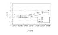
圖2A示出在X方向上具有3個交叉點的圖1所示系統的一部分。Figure 2A shows a part of the system shown in Figure 1 with 3 intersections in the X direction.
圖2B至圖2E是示出交叉點的移動對各種參數的影響的曲線圖。2B to 2E are graphs showing the influence of the movement of the intersection on various parameters.
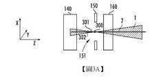
圖3A示出在Z方向上具有3個交叉點的圖1所示系統的一部分。Figure 3A shows a part of the system shown in Figure 1 with 3 intersections in the Z direction.
圖3B至圖3E是示出交叉點的移動對各種參數的影響的曲線圖。3B to 3E are graphs showing the influence of the movement of the intersection on various parameters.
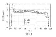
圖4A示出具有2個交叉點的圖1所示系統的一部分。Figure 4A shows a part of the system shown in Figure 1 with 2 intersections.
圖4B至圖4E是示出交叉點的移動對各種參數的影響的曲線圖。4B to 4E are graphs showing the influence of the movement of the intersection on various parameters.
圖5示出根據一個實施例的品質分辨裝置移動器(mass resolving device mover)。Figure 5 shows a mass resolving device mover according to one embodiment.
圖6是示出使用圖1所示系統來微調帶狀離子束的方法的流程圖。Fig. 6 is a flowchart showing a method of fine-tuning a ribbon ion beam using the system shown in Fig. 1.
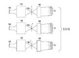
圖7示出圖1所示系統的另一應用。Fig. 7 shows another application of the system shown in Fig. 1.
圖8示出圖1所示系統的第三應用。Fig. 8 shows a third application of the system shown in Fig. 1.
圖1示出根據一個實施例可用於微調帶狀離子束的束線離子植入系統。所述束線離子植入系統可用於使用帶狀離子束來處理工件。Figure 1 shows a beamline ion implantation system that can be used to fine-tune a ribbon ion beam according to one embodiment. The beamline ion implantation system can be used to process a workpiece using a ribbon ion beam.
所述束線離子植入系統包括離子源100,離子源100包括界定離子源腔室的多個腔室壁。在某些實施例中,離子源100可為射頻(radio frequency,RF)離子源。在此實施例中,RF天線可抵靠介電窗而設置。此介電窗可構成腔室壁中的一者的一部分或全部。RF天線可包含導電材料,例如銅。RF電源與RF天線進行電通信。RF電源可向RF天線供應RF電壓。由RF電源供應的電力可介於0.1kW與10kW之間,且可為任何適合的頻率,例如介於1MHz與100MHz之間。此外,由RF電源供應的電力可為脈衝式。The beamline ion implantation system includes an
在另一實施例中,在離子源腔室內設置有陰極。導絲(filament)設置在陰極後面且被通電以發射電子。這些電子被吸引到陰極,所述陰極又將電子發射到離子源腔室中。此陰極可被稱為間熱式陰極(indirectly heated cathode,IHC),因為所述陰極是通過從導絲發射出的電子被間接地加熱。In another embodiment, a cathode is provided in the ion source chamber. A filament is arranged behind the cathode and is energized to emit electrons. These electrons are attracted to the cathode, which in turn emits the electrons into the ion source chamber. This cathode may be called an indirectly heated cathode (IHC) because the cathode is indirectly heated by electrons emitted from the guide wire.
還可能存在其他實施例。舉例來說,可以不同的方式(例如通過伯納(Bernas)離子源、電容耦合等離子(capacitively coupled plasma,CCP)源、微波離子源或電子迴旋共振(electron-cyclotron-resonance,ECR)離子源)生成等離子。生成等離子的方式並不受本發明限制。Other embodiments are also possible. For example, it can be done in different ways (for example, by Bernas ion source, capacitively coupled plasma (CCP) source, microwave ion source or electron cyclotron resonance(electron-cyclotron-resonance, ECR) ion source) generates plasma. The way of generating plasma is not limited by the present invention.
被稱為抽取板的一個腔室壁包括抽取開孔。所述抽取開孔可為抽取並朝工件10引導在離子源腔室中生成的離子1所經由的開口。所述抽取開孔可為任何適合的形狀。在某些實施例中,所述抽取開孔可為卵形的或矩形的,從而使得其被稱為寬度的一個尺寸(x尺寸)可比被稱為高度的第二尺寸(y尺寸)大得多。這樣一來,離子是以帶狀束的形式被抽取。One chamber wall called the extraction plate includes extraction openings. The extraction opening may be an opening through which the
在離子源100的抽取開孔之外且接近所述抽取開孔處設置有抽取光學器件110。在某些實施例中,抽取光學器件110包括一個或多個電極。每一電極可為其中設置有開孔的單個導電組件。作為另外一種選擇,每一電極可由兩個導電組件構成,所述兩個導電元件間隔開以在所述兩個元件之間形成開孔。電極可為金屬,例如鎢、鉬或鈦。電極中的一者或多者可電連接到地。在某些實施例中,可使用電極電源對電極中的一者或多者施加偏壓。電極電源可用于相對於離子源100對電極中的一者或多者施加偏壓,以經由抽取開孔吸引離子1。抽取開孔與抽取光學器件110中的開孔對準,以使得離子1穿過這兩個開孔。An extraction
位於抽取光學器件110下游的可為第一四極透鏡120。第一四極透鏡120與系統中的其他四極透鏡協作,以將離子1聚焦成離子束。Located downstream of the extraction
位於第一四極透鏡120下游的是品質分析儀130。品質分析儀130使用磁場來導引所抽取離子1的路徑。所述磁場根據離子的品質及電荷而影響離子的飛行路徑。在品質分析儀130的輸出或遠端處設置有具有分辨開孔151的品質分辨裝置150。通過恰當地選擇磁場,僅那些具有所選品質及電荷的離子1將被引導穿過分辨開孔151。其他離子將射到品質分辨裝置150上或者品質分析儀130的壁上且在所述系統中將不再有任何行進。品質分辨裝置150可與品質分辨裝置移動器155連通,以下會更詳細地闡述品質分辨裝置移動器155。Located downstream of the
在品質分析儀130的輸出與品質分辨裝置150之間可設置有第二四極透鏡140。A
准直器180設置在品質分辨裝置150的下游。准直器180接受穿過分辨開孔151的離子1,並形成由多個平行的或幾乎平行的子束形成的帶狀離子束。品質分析儀130的輸出或遠端與准直器180的輸入或近端可隔開固定的距離。品質分辨裝置150設置在這兩個元件之間的空間中。The
在品質分辨裝置150與准直器180的輸入之間可設置有第三四極透鏡160。在品質分辨裝置150與准直器180的輸入之間也可設置有第四四極透鏡170。A
在某些實施例中,所述四極透鏡可設置在其他位置中。舉例來說,第三四極透鏡160可設置在第二四極透鏡140與品質分辨裝置150之間。另外,在某些實施例中,所述四極透鏡中的一者或多者可被省略。In some embodiments, the quadrupole lens may be arranged in other positions.For example, the
位於准直器180下游的可為加速級/減速級190。加速級/減速級190可被稱為能量純度模組(energy purity module)。所述能量純度模組是被配置成獨立地對離子束的偏轉、減速及聚焦進行控制的束線透鏡元件。舉例來說,所述能量純度模組可為垂直靜電能量篩檢程式(vertical electrostatic energy filter,VEEF)或靜電篩檢程式(electrostatic filter,EF)。Located downstream of the
離子1被抽取成具有寬度的帶狀束,所述帶狀束由圖中的陰影區表示。在離子1行進穿過系統時,離子1的路徑可被彎曲、變窄、展寬或以其他方式被變更。在附圖中,離子1的路徑被示出為陰影區。圖1中說明離子1在離子行進穿過束線離子植入系統時的中心軌跡2。在離子穿過品質分析儀130時,帶狀束的一端上的離子被操縱成使得這些離子與帶狀束的相對一端交叉。圖1示出:所需物質的所有離子1均在品質分析儀130的遠端之後相交於一點處,而不管所有離子1在品質分析儀130中在帶狀束中的原始位置如何。在本發明通篇中,此點被稱為交叉點。在某些實施例中,分辨開孔151的中心與交叉點對準。The
集流器191可用於測量與帶狀離子束相關聯的某些參數,所述參數包括束流、均值水平角及水平角展度。集流器191可包括一個或多個法拉第(Faraday)裝置。所述法拉第裝置收集電流,且能夠測量由裝置收集的電流量。所述法拉第裝置還能夠確定射到裝置上的離子的入射角,以便可在多個位置處確定均值水平角。儘管集流器191被示出為是在工件10附近,然而,應理解,其可沿著束線位於其他位置中。舉例來說,在一個實施例中,集流器191可設置於在操作期間通常由工件10佔據的位置中。這樣一來,集流器191提供表示由工件10經受的電流的回饋。The
還使用控制器195來控制所述系統。控制器195具有處理單元及相關聯的記憶體裝置。此記憶體裝置含有指令,所述指令在由所述處理單元執行時使所述系統能夠執行本文中所述的功能。此記憶體裝置可為任何非暫時性存儲媒體,包括非易失性記憶體,例如快閃記憶體唯讀記憶體(read only memory,ROM)、電可擦除唯讀記憶體或其他適合的裝置。在其他實施例中,所述記憶體裝置可為易失性記憶體,例如隨機存取記憶體(random access memory,RAM)或動態隨機存取記憶體(dynamic random access memory,DRAM)。在某些實施例中,控制器195可為通用電腦、嵌入式處理器或經專門設計的微控制器。控制器195的實際實施方案並不受本發明限制。The
控制器195可與四極透鏡、品質分析儀130及品質分辨裝置移動器155中的每一者進行通信。另外,控制器195可與集流器191進行通信,以使得控制器195可基於實際的所測量參數對這些元件的操作進行優化或改善。The
在本發明中,品質分辨裝置150能夠由品質分辨裝置移動器155在X方向及Z方向上移動。舉例來說,品質分辨裝置150可被移動成距品質分析儀130的輸出更近或距准直器180的輸入更近。Z方向被定義為在離子束移動穿過系統時離子束的中心軌跡2的方向。舉例來說,在分辨開孔151處,Z方向是從左向右,如圖例中的坐標軸所示且如中心軌跡2所指示。然而,Z方向隨著離子束移動穿過束線離子植入系統而改變,因為中心軌跡2隨著離子束移動穿過各種元件而改變方向。因此,Z方向始終與中心軌跡2相切。X方向被定義為分辨開孔151的寬度及離子束的寬度的方向。Y方向被定義為離子束的高度方向。因此,X方向平行於帶狀離子束的長尺寸,而Y軸平行於帶狀離子束的短尺寸。X方向被定義成垂直於離子的中心軌跡2(即,Z方向)及Y方向。在說明了坐標系統的所有圖中,所述坐標系統示出分辨開孔151處的座標。In the present invention, the
通常,品質分辨裝置150的分辨開孔151可沿著品質分析儀130的輸出與准直器180的輸入的中心線被定位。舉例來說,分辨開孔151可被定位在准直器180的光學焦點處。另外,品質分析儀130的磁場被配置成使得所需離子的交叉點位於分辨開孔151的中心處,如圖1中所示。Generally, the resolution opening 151 of the
准直器180負責形成跨所關注區(ROI)具有大致恒定束流的離子束且形成構成帶狀離子束的實質上平行的子束。The
意外地,已發現,通過使所需離子的交叉點相對於准直器180的輸入或品質分辨裝置150下游的另一元件的輸入而移動,可對束流、水平角分佈及均值水平角進行操縱。Unexpectedly, it has been found that by moving the cross point of the desired ion relative to the input of the
在某些實施例中,可通過改變在品質分析儀130中施加的磁場而使所需離子的交叉點在X方向上移動。這可由控制器195執行。可通過改變四極透鏡(例如第一四極透鏡120及第二四極透鏡140)的參數而使所需離子的交叉點在Z方向上移動。此外,如果第三四極透鏡160位於品質分辨裝置150之前,則也可改變第三四極透鏡160的參數來使交叉點移動。同樣,這可由控制器195執行。In some embodiments, the cross point of the desired ions can be moved in the X direction by changing the magnetic field applied in the
圖2A示出與圖1所示配置相同的配置中離子1的中心軌跡2、第二四極透鏡140、品質分辨裝置150及第三四極透鏡160。點200表示傳統配置中所需離子的交叉點,其中所述交叉點與品質分析儀130的輸出的中心線及准直器180的光學焦點對準。點201示出第二潛在交叉點,其相對於點200在正X方向上移動了約5mm至10mm。如上所述,可通過調整品質分析儀130中的磁場來形成此第二潛在交叉點(即,點201)。點202示出第三潛在交叉點,其相對於點200在正X方向上移動了約10mm至20mm。如上所述,可通過調整品質分析儀130中的磁場來形成此第三潛在交叉點(即,點202)。雖然圖中未示出,然而應理解,也可使交叉點在負X方向上移動。此外,儘管圖中未示出,然而應理解,分辨開孔151的中心也被移動以對應於交叉點。2A shows the
圖2B示出使用所述3個潛在交叉點中的每一者而產生且表示帶狀離子束的束流密度隨在X方向上的位置而變化的三條線。線210對應於點200;線211對應於點201;且線212對應於點202。X軸表示在工件10的位置處帶狀離子束在X方向上的位置,測量單位為毫米。Y軸表示電流密度,測量單位為mA/cm。可使用集流器191來執行這些測量。在某些實施例中,通過使法拉第裝置移動而在工件10的位置處進行束流測量。這些測量是在帶狀離子束被進行均勻度微調之前進行。應注意,束流分佈(beam current profile)受交叉點在X方向上的移動影響。具體來說,隨著交叉點在X方向上移動,束一端上的束流減小,而帶狀離子束的相對一端上的束流增大。圖2C示出使用所述3個潛在交叉點中的每一者而產生且表示經均勻度微調的帶狀離子束的束流密度隨在X方向上的位置而變化的三條線。線220對應於點200;線221對應於點201;且線222對應於點202。如在圖2C中可看出,交叉點在X方向上的移動對整個所關注區上的電流密度具有小的影響。事實上,對於點200,所關注區中的電流是41.7mA,而對於點202,ROI中的電流是幾乎相同的。FIG. 2B shows three lines that are generated using each of the three potential intersection points and indicate that the beam current density of the ribbon ion beam varies with the position in the X direction.
圖2D示出在工件10的位置處沿著帶狀離子束在七個點處測量的平均水準束角(average horizontal beam angle)。具體來說,集流器191在帶狀離子束的沿著X方向的七個位置中的每一者中測量平行的子束的均值水平角。此曲線圖示出使用所述3個潛在交叉點中的每一者而產生且表示帶狀離子束的平均水準束角隨在X方向上的位置而變化的三條線。線230對應於點200;線231對應於點201;且線232對應於點202。X軸表示帶狀離子束中在X方向上的7個位置中的每一者。Y軸表示均值水平角,測量單位為度。此資料是在帶狀離子束被進行均勻度微調之前測得。圖2E表示經微調帶狀離子束的相同資訊。線240對應於點200;線241對應於點201;且線242對應於點202。2D shows the average horizontal beam angle (average horizontal beam angle) measured at seven points along the ribbon ion beam at the position of the
圖2E示出均值水準束角受交叉點在X方向上的移動的嚴重影響。線240示出1.19°的均值水平角以及0.62°的水平角展度。水平角展度被定義為所述7個位置的最大水平角減去所述7個位置的均值水平角。此值近似是七個所收集值的3σ值。相比之下,線242示出0.27°的均值水平角以及0.56°的水平角展度。Figure 2E shows that the mean level beam angle is severely affected by the movement of the intersection in the X direction.
因此,綜上所述,交叉點及分辨開孔151的中心在X方向上的移動對束流及水平角展度具有很小影響。然而,交叉點及分辨開孔151的中心在X方向上的移動確實會影響均值水平角。交叉點及分辨開孔151的中心在X方向上的移動還影響帶狀離子束的電流分佈。Therefore, in summary, the movement of the intersection point and the center of the resolution opening 151 in the X direction has little effect on the beam current and the horizontal angular spread. However, the movement of the intersection point and the center of the resolution opening 151 in the X direction does affect the mean horizontal angle.The movement of the intersection point and the center of the resolution opening 151 in the X direction also affects the current distribution of the ribbon ion beam.
圖3A示出與圖1所示配置相同的配置中離子1的中心軌跡2、第二四極透鏡140、品質分辨裝置150及第三四極透鏡160。點300表示傳統配置中所需離子的交叉點,其中所述交叉點與品質分析儀130的輸出的中心線及准直器180的光學焦點對準。點301示出第二潛在交叉點,其相對於點300在負Z方向上移動了大約10mm。如上所述,可通過調整第一四極透鏡120及第二四極透鏡140中的至少一者的參數來形成此第二潛在交叉點(即,點301)。如前面所述,在某些實施例中,可調整第三四極透鏡160的參數。點301比點300距品質分析儀130的輸出更近。點302示出第三潛在交叉點,其相對於點300在負Z方向上移動了大約20mm。如上所述,可通過調整四極透鏡中的至少一者的參數來形成此第三潛在交叉點(即,點302)。點302比點301距品質分析儀130的輸出更近。儘管圖中未示出,然而也可使交叉點在正Z方向上移動。此外,儘管圖中未示出,然而應理解,分辨開孔151的中心也被移動以對應於交叉點。3A shows the
圖3B示出使用所述3個潛在交叉點中的每一者而產生且表示在工件10的位置處測量的帶狀離子束的束流密度隨在X方向上的位置而變化的三條線。線310對應於點300;線311對應於點301;且線312對應於點302。如上所述,X軸表示在工件10的位置處帶狀離子束在X方向上的位置,測量單位為毫米。Y軸表示電流密度,測量單位為mA/cm。這些測量是在帶狀離子束被進行均勻度微調之前進行。圖3C示出使用所述3個潛在交叉點中的每一者而產生且表示經均勻度微調的帶狀離子束的束流密度隨在X方向上的位置而變化的三條線。線320對應於點300;線321對應於點301;且線322對應於點302。如在圖3C中可看出,交叉點及分辨開孔151的中心在負Z方向上的移動對整個所關注區上的電流密度具有負面影響。事實上,對於點300,所關注區中的電流是41.7mA,而對於點302,ROI中的電流小約10%。FIG. 3B shows three lines generated using each of the three potential intersection points and indicating that the beam current density of the ribbon ion beam measured at the position of the
圖3D示出沿著帶狀離子束的七個點處的平均水準束角。此曲線圖示出使用所述3個潛在交叉點中的每一者而產生且表示帶狀離子束的平均水準束角隨在X方向上的位置而變化的三條線。線330對應於點300;線331對應於點301;且線332對應於點302。X軸表示帶狀離子束在X方向上的7個位置中的每一者。Y軸表示均值水平角,測量單位為度。此資料是在帶狀離子束被進行均勻度微調之前測得。圖3E表示經均勻度微調的帶狀離子束的相同資訊。線340對應於點300;線341對應於點301;且線342對應於點302。Figure 3D shows the average horizontal beam angle at seven points along the ribbon ion beam. This graph shows three lines generated using each of the three potential intersection points and representing the average horizontal beam angle of the ribbon ion beam as a function of the position in the X direction.
圖3E示出均值水平角及水平角展度均受交叉點及分辨開孔151的中心在Z方向上的移動的影響。線340示出1.19°的均值水平角以及0.62°的水平角展度。相比之下,線342示出0.71°的均值水平角以及0.51°的水平角展度。FIG. 3E shows that the mean horizontal angle and the horizontal angular spread are both affected by the movement of the intersection point and the center of the resolution opening 151 in the Z direction. Line 340 shows a mean horizontal angle of 1.19° and a horizontal angular spread of 0.62°. In contrast,
因此,綜上所述,交叉點及分辨開孔151的中心在Z方向上的移動對束流具有稍微負面的影響且對均值水平角及水平角展度具有正面影響。Therefore, in summary, the movement of the intersection point and the center of the resolution opening 151 in the Z direction has a slightly negative effect on the beam current and has a positive effect on the mean horizontal angle and the horizontal angular spread.
儘管前述各圖示出交叉點及分辨開孔151的中心在一個方向上的移動的影響,然而應理解,可使交叉點及分辨開孔151的中心在兩個方向上移動。Although the foregoing figures show the influence of the intersection and the center of the
圖4A示出在與圖1所示配置相同的配置中離子的中心軌跡2、第二四極透鏡140、品質分辨裝置150及第三四極透鏡160。點400表示傳統配置中所需離子的交叉點,其中所述交叉點與品質分析儀130的輸出的中心線及准直器180的光學焦點對準。點401示出第二潛在交叉點,其相對於點400在正X方向上移動了約6mm且在負Z方向上移動了約12mm。如上所述,可通過調整品質分析儀130中的磁場並通過調整第一四極透鏡120及第二四極透鏡140中的至少一者的參數來形成此第二潛在交叉點(即,點401)。點401比點400距品質分析儀130的輸出更近。此外,儘管圖中未示出,然而應理解,分辨開孔151的中心也被移動以對應於交叉點。FIG. 4A shows the
圖4B示出使用所述2個潛在交叉點中的每一者而產生且表示帶狀離子束的束流密度隨在X方向上的位置而變化的兩條線。線410對應於點400;且線411對應於點401。如上所述,X軸表示在工件10的位置處帶狀離子束在X方向上的位置,測量單位為毫米。Y軸表示電流密度,測量單位為mA/cm。這些測量是在帶狀離子束被微調之前進行。有趣地,通過將交叉點從點400移動到點401,束流是略小的,而束流分佈是更均勻的,這可有益於均勻度微調。圖4C示出使用所述2個潛在交叉點中的每一者而產生且表示經微調帶狀離子束的束流密度隨在X方向上的位置而變化的兩條線。線420對應於點400;且線421對應於點401。如在圖4C中可看出,交叉點在X方向及Z方向上的移動對整個所關注區上的電流密度具有略負面的影響。事實上,對於點400,所關注區中的電流是41.7mA,而對於點401,ROI中的電流小約5%。FIG. 4B shows two lines that are generated using each of the two potential intersection points and indicate that the beam current density of the ribbon ion beam varies with the position in the X direction.
圖4D示出沿著帶狀離子束的七個點處的平均水準束角。此曲線圖示出使用所述2個潛在交叉點中的每一者而產生且表示帶狀離子束的平均水準束角隨在X方向上的位置而變化的兩條線。線430對應於點400;且線431對應於點401。X軸表示帶狀離子束在X方向上的7個位置中的每一者。Y軸表示均值水平角,測量單位為度。此資料是在帶狀離子束被進行均勻度微調之前測得。圖4E表示經微調帶狀離子束的相同資訊。線440對應於點400;且線441對應於點401。Figure 4D shows the average horizontal beam angle at seven points along the ribbon ion beam. This graph shows two lines generated using each of the 2 potential intersection points and representing the average horizontal beam angle of the ribbon ion beam as a function of the position in the X direction.
圖4E示出均值水平角及水平角展度均受交叉點及分辨開孔151的中心在X方向及Z方向上的移動的正面影響。線440示出1.19°的均值水平角以及0.62°的水平角展度。相比之下,線441示出0.54°的均值水平角以及0.34°的水平角展度。因此,在一個測試中,可通過使交叉點及分辨開孔151的中心在X方向及Z方向上移動而實現均值水平角的55%減小及水平角展度的45%減小。4E shows that the mean horizontal angle and the horizontal angular spread are both positively affected by the movement of the intersection point and the center of the resolution opening 151 in the X direction and the Z direction.
因此,可通過使從品質分析儀130射出的所需物質的交叉點在X方向及Z方向上平移來對帶狀離子束的參數(例如束流、均值水平角及水平角展度)進行操縱及優化。分辨開孔151的中心也被移動以與交叉點對準。Therefore, the parameters of the ribbon ion beam (such as beam current, mean horizontal angle, and horizontal angular spread) can be manipulated by shifting the intersection point of the desired substance emitted from the
前述各圖中所示的結果是在一組特定測試期間獲得。視對各種指令引數(例如束能量、離子物質及抽取束流)的選擇而定,各結果可變化。因此,呈現這些結果是為了說明與交叉點的移動相關聯的趨勢。The results shown in the previous figures were obtained during a specific set of tests. Depending on the choice of various instruction parameters (such as beam energy, ion species, and extraction beam current), the results can vary. Therefore, these results are presented to illustrate the trends associated with the movement of intersections.
圖5示出根據一個實施例的品質分辨裝置移動器155的示意圖。FIG. 5 shows a schematic diagram of a quality
品質分辨裝置移動器155可設置在束線離子植入系統的主殼體之外。舉例來說,壁500可將束線離子植入系統與外部環境分隔開。品質分辨裝置150設置在主殼體之內。品質分辨裝置150可包括由分辨開孔151分隔開的第一部分152及第二部分153。在一些實施例中,第一部分152由第一杆501支撐,且第二部分153由第二杆502支撐。第一杆501及第二杆502可穿過壁500且與間隔馬達510連通。間隔馬達510能夠使第一杆501與第二杆502在相反的方向上獨立地移動。這樣一來,間隔馬達510能夠在X方向上調整分辨開孔151的寬度。接近間隔馬達510定位的是X調整馬達520。X調整馬達520能夠使間隔馬達510在X方向上移動。這起到使第一部分152與第二部分153一起移動的作用。換句話說,間隔馬達510設定分辨開孔151的寬度,且X調整馬達520使分辨開孔151的中心在X方向上移動。在另一實施例中,可將間隔馬達510與X調整馬達520組合,以使得單個馬達控制分辨開孔151的寬度及分辨開孔151的中心的X位置。Z調整馬達530能夠使間隔馬達510及X調整馬達520在Z方向上移動。控制器195可與間隔馬達510、X調整馬達520及Z調整馬達530進行通信,以控制分辨開孔151的寬度及分辨開孔151的中心的位置。The mass
如上所述,本發明闡述可在X方向上移動的品質分辨裝置150。應理解,改變分辨開孔151的寬度涉及X方向上的移動。然而,本發明也闡述了其中使分辨開孔151的中心在X方向上移動的X方向移動。As described above, the present invention describes the
因此,在一個實施例中,本發明闡述一種束線離子植入系統,其中品質分辨裝置150具有分辨開孔151,分辨開孔151的中心可在X方向及Z方向上移動。所述束線離子植入系統還包括控制器195,控制器195能夠控制品質分析儀130及四極透鏡,以使得所需離子的交叉點可在X方向及Z方向上移動。在一些實施例中,控制器195能夠控制品質分析儀130及其他元件,以使得離子的中心軌跡2在至少一個方向(例如X方向)上移位。分辨開孔151、離子的中心軌跡2及交叉點的移動可使得帶狀離子束的一些參數能夠被優化或改善。Therefore, in one embodiment, the present invention describes a beamline ion implantation system, in which the
在另一實施例中,所述束線離子植入系統包括具有分辨開孔151的品質分辨裝置150,分辨開孔151的中心可在一個方向(X方向或Z方向)上移動。所述束線離子植入系統還包括控制器195,控制器195能夠控制品質分析儀130及四極透鏡,以使得所需離子的交叉點可在X方向或Z方向上移動。在此實施例中,所述束線離子植入系統中可不包含X調整馬達520或Z調整馬達530中的一者。In another embodiment, the beamline ion implantation system includes a
當然,也可能存在其他配置。舉例來說,可使用更複雜的方案(例如使用壓電式或真空式線性馬達)來實現相同的結果。Of course, other configurations may also exist. For example, more complex schemes (such as using piezoelectric or vacuum linear motors) can be used to achieve the same result.
在另一配置中,可從離子源100抽取點束。所述點束可行進穿過品質分析儀130及品質分辨裝置150。在此實施例中,可採用或者可不採用四極透鏡。然後,點束可進入設置在准直器180與品質分辨裝置150之間的掃描器。所述掃描器使點束被扇出成多個發散子束。掃描器可為靜電或磁性的。然後,准直器180將這些發散子束轉換成多個平行的子束,以形成帶狀離子束。在此實施例中,控制器195可控制品質分析儀130使離子的中心軌跡2在X方向或Y方向上移動。品質分辨裝置150也被移動,以使得分辨開孔151的中心與中心軌跡2對準。此中心軌跡2可不與掃描器的中心線對準。中心軌跡2及分辨開孔151的中心的此種移動可影響所形成的帶狀離子束的各種參數,包括會聚度、發散度、電流分佈、均值水平角及水平角展度。In another configuration, the spot beam can be extracted from the
圖6說明流程圖,其示出其中控制器195可對帶狀離子束的參數進行優化或改善的一個實施例。此序列可由控制器195控制。FIG. 6 illustrates a flowchart showing an embodiment in which the
首先,如方框600中所示,對圖1所示束線離子植入系統應用初始設定。此初始設定可包括四極透鏡、品質分析儀130及其他元件的初始值。使用集流器191,控制器195可分析帶狀離子束的各種參數(例如跨所關注區的束流、束均值水平角及水平角展度),如方框610中所示。控制器195可基於這些所測量的參數來確定品質因數。在一個實施例中,所述品質因數可被定義為w1×I+w2×(均值水平角)+w3 *(水平角展度),其中w1、w2及w3是加權係數且I是所測量束流或簡稱為「束流」。然後,控制器195將品質因數與預定限值進行比較,如方框620中所示。如果品質因數是不可接受的,則控制器195調整交叉點及分辨開孔151的X位置,如方框630中所示。然後,控制器195使用集流器191來收集資訊,以便可分析帶狀離子束的各種參數,如方框610中所示。然後,控制器195使用交叉點及分辨開孔151的被調整後的X位置來再次檢查品質因數,如方框620中所示。First, as shown in
一旦品質因數在預定限值之內,控制器195便判斷水平角展度是否在預定限值之內,如方框640中所示。如果水平角展度不在預定限值之內,則控制器195調整交叉點及分辨開孔151的Z位置,如方框650中所示。然後,控制器195使用集流器191來收集資訊,以便可分析帶狀離子束的各種參數,如方框660中所示。然後,控制器195使用交叉點及分辨開孔151的新Z位置來再次檢查水平角展度,如方框640中所示。一旦水平角展度在預定限值之內,微調過程便完成。圖6所示的序列使用以下事實:當交叉點及分辨開孔151的Z位置移動時,均值水平角及束流實質上不受影響。Once the quality factor is within the predetermined limit, the
在另一實施例中,控制器195可執行更詳盡的分析,以將帶狀離子束的參數優化。舉例來說,控制器195可為交叉點及分辨開孔151設定初始X位置。然後,控制器195可在維持此X位置的同時使用集流器191在多個Z位置處進行測量。然後,控制器195可將分辨開孔151及交叉點移動到第二X位置,且在維持此第二X位置的同時在多個Z位置處進行測量。這可重複多次。一旦所有X位置被分析,控制器195便可具有使得能夠確定交叉點的最優配置的資料。換句話說,控制器195將創建其中以交叉點的X位置及Z位置作為兩個維度的二維矩陣。矩陣中每一點處的值表示帶狀離子束的和X位置與Z位置的所述組合相關聯的參數。在其他實施例中,矩陣中每一點處的值可表示從帶狀離子束的參數匯出的品質因數。In another embodiment, the
本文中所述的系統及方法具有許多優點。如上所述,時常,在對跨所關注區的束流均勻度與對均值水平角及水平角展度的優化之間存在衝突。高束流均勻度可導致高於期望值的水平角展度。通過操縱所需離子的交叉點並相應地使品質分辨裝置150移動,可將另一種微調機制併入到系統中。因此,如圖4E中所示,在對束流具有微小負面影響的同時改善了均值水平角及水平角展度。The systems and methods described in this article have many advantages. As mentioned above, there is often a conflict between the uniformity of the beam across the region of interest and the optimization of the mean horizontal angle and horizontal angular spread. High beam uniformity can result in a higher than desired horizontal angular spread. By manipulating the intersection of the desired ions and moving the
儘管以上公開內容闡述了其中將帶狀離子束優化以減小均值水平角及水平角展度的系統,然而也可能存在其他實施例。舉例來說,交叉點及分辨開孔151在Z方向上的移動可具有其他用途。圖7示出圖1所示系統的高級表示,其中示出品質分析儀130、品質分辨裝置150及准直器180。在傳統系統中,如頂部例圖上所示,所得的離子束由平行的或實質上平行的子束構成。如果使品質分辨裝置150在正Z方向上朝准直器180移動,則如中間例圖中所示,可形成發散離子束。相反地,如果使品質分辨裝置在負Z方向上朝品質分析儀130移動,則如底部例圖中所示,可形成會聚離子束。Although the above disclosure describes a system in which the ribbon ion beam is optimized to reduce the mean horizontal angle and horizontal angular spread, other embodiments are possible.For example, the intersection point and the movement of the
形成會聚離子束及發散離子束的能力對於定向離子束處理(例如定向刻蝕及/或沉積製程)可為有用的,所述定向離子束處理對於不同的裝置結構及應用常常利用發散束及會聚束。The ability to form convergent ion beams and divergent ion beams may be useful for directional ion beam processing (such as directional etching and/or deposition processes), which often utilize divergent beams and convergent beams for different device structures and applications. bundle.
此實施例也具有其他優點。將品質分辨裝置150在Z方向上定位在不同的位置處的能力可用於處理大小不同的襯底,所述大小不同的襯底可利用略不同的束寬度。This embodiment also has other advantages. The ability to position the
另外,使品質分辨裝置150在X方向及Z方向上平移的能力使得能夠有意地生成非均勻的帶狀離子束。這些非均勻的帶狀離子束對於超掃描應用及選擇性區域處理應用可潛在地為有用的。圖8示出交叉點在X方向上以及在X方向及Z方向上的移動的影響的數個實例。圖8示出圖1所示系統的高級表示,其中示出品質分析儀130、品質分辨裝置150及准直器180。如頂部例圖上所示,如果使交叉點在X方向上移動,則引入不對稱性。舉例來說,離子束可在帶狀離子束的一端處具有更大的束流。然而,由於不使交叉點在Z方向上移動,因此所得的離子束由平行或實質上平行的子束構成。如果使品質分辨裝置150在正Z方向及正X方向上移動,則如中間例圖中所示,可形成非對稱的發散離子束。相反地,如果使品質分辨裝置150在負Z方向及正X方向上移動,則如底部例圖中所示,可形成非對稱的會聚離子束。In addition, the ability to translate the
因此,在另一實施例中,所述束線離子植入系統包括品質分辨裝置150,其中分辨開孔151的中心不與准直器180的光學焦點對準。此外,所需離子的交叉點也不與准直器180的光學焦點對準,但與分辨開孔151的中心對準。可調整交叉點,以在離子束中形成特定特性。所述特性可為以下參數中的任一者或全部:會聚度、發散度、束流非對稱性、束流、均值水平角或水平角展度。Therefore, in another embodiment, the beamline ion implantation system includes a
本發明的範圍不受本文所述的具體實施例限制。實際上,通過閱讀以上說明及附圖,對所屬領域中的一般技術人員來說,除本文所述實施例及潤飾以外,本發明的其他各種實施例及對本發明的各種潤飾也將顯而易見。因此,這些其他實施例及潤飾都旨在落于本發明的範圍內。此外,儘管已針對特定目的而在特定環境中在特定實施方案的上下文中闡述了本發明,然而所屬領域中的一般技術人員將認識到,本發明的效用並非僅限於此且可針對任何數目的目的在任何數目的環境中有益地實施本發明。因此,應考慮到本文所述本發明的全部範圍及精神來理解以上提出的權利要求書。The scope of the present invention is not limited by the specific embodiments described herein. actualAbove, by reading the above description and the drawings, it will be obvious to those skilled in the art that in addition to the embodiments and modifications described herein, other various embodiments of the present invention and various modifications to the present invention will also be apparent. Therefore, these other embodiments and modifications are intended to fall within the scope of the present invention. In addition, although the present invention has been described in the context of specific embodiments in a specific environment for a specific purpose, those of ordinary skill in the art will recognize that the utility of the present invention is not limited to this and can be directed to any number of The purpose is to implement the invention beneficially in any number of environments.Therefore, the full scope and spirit of the invention described herein should be considered to understand the claims presented above.
1:離子1: ion
2:中心軌跡2: Center track
10:工件10: Workpiece
100:離子源100: ion source
110:抽取光學器件110: Extraction optics
120:第一四極透鏡120: The first quadrupole lens
130:品質分析儀130: Quality Analyzer
140:第二四極透鏡140: second quadrupole lens
150:品質分辨裝置150: Quality discrimination device
151:分辨開孔151: Resolve the opening
155:品質分辨裝置移動器155: Quality resolution device mover
160:第三四極透鏡160: third quadrupole lens
170:第四四極透鏡170: The fourth quadrupole lens
180:准直器180: collimator
190:加速級/減速級190: acceleration stage/deceleration stage
191:集流器191: Collector
195:控制器195: Controller
X、Y、Z:方向X, Y, Z: direction
Claims (12)
Translated fromChineseApplications Claiming Priority (2)
| Application Number | Priority Date | Filing Date | Title |
|---|---|---|---|
| US15/850,184US11049691B2 (en) | 2017-12-21 | 2017-12-21 | Ion beam quality control using a movable mass resolving device |
| US15/850,184 | 2017-12-21 |
Publications (2)
| Publication Number | Publication Date |
|---|---|
| TW201929023A TW201929023A (en) | 2019-07-16 |
| TWI705471Btrue TWI705471B (en) | 2020-09-21 |
Family
ID=66951450
Family Applications (1)
| Application Number | Title | Priority Date | Filing Date |
|---|---|---|---|
| TW107138877ATWI705471B (en) | 2017-12-21 | 2018-11-02 | Beam line ion implantation system and method of tuning a ribbon ion beam |
Country Status (3)
| Country | Link |
|---|---|
| US (1) | US11049691B2 (en) |
| TW (1) | TWI705471B (en) |
| WO (1) | WO2019125597A1 (en) |
Families Citing this family (2)
| Publication number | Priority date | Publication date | Assignee | Title |
|---|---|---|---|---|
| US20210398772A1 (en)* | 2020-06-17 | 2021-12-23 | Axcelis Technologies, Inc. | Tuning apparatus for minimum divergence ion beam |
| US11574796B1 (en) | 2021-07-21 | 2023-02-07 | Applied Materials, Inc. | Dual XY variable aperture in an ion implantation system |
Citations (6)
| Publication number | Priority date | Publication date | Assignee | Title |
|---|---|---|---|---|
| US4757208A (en)* | 1986-03-07 | 1988-07-12 | Hughes Aircraft Company | Masked ion beam lithography system and method |
| TW200739648A (en)* | 2006-01-20 | 2007-10-16 | Varian Semiconductor Equipment | Methods and apparatus for ion beam angle measurement in two dimensions |
| US20090179161A1 (en)* | 2003-10-16 | 2009-07-16 | Alis Corporation | Ion sources, systems and methods |
| US8637838B2 (en)* | 2011-12-13 | 2014-01-28 | Axcelis Technologies, Inc. | System and method for ion implantation with improved productivity and uniformity |
| US20140261173A1 (en)* | 2013-03-15 | 2014-09-18 | Glenn Lane Family Limited Liability Limited Partnership | Adjustable mass resolving aperture |
| US20160189917A1 (en)* | 2014-12-26 | 2016-06-30 | Axcelis Technologies, Inc. | Systems and methods for beam angle adjustment in ion implanters with beam decelaration |
Family Cites Families (11)
| Publication number | Priority date | Publication date | Assignee | Title |
|---|---|---|---|---|
| US5130552A (en) | 1990-12-17 | 1992-07-14 | Applied Materials, Inc. | Improved ion implantation using a variable mass resolving system |
| US5629528A (en) | 1996-01-16 | 1997-05-13 | Varian Associates, Inc. | Charged particle beam system having beam-defining slit formed by rotating cyclinders |
| GB9813327D0 (en)* | 1998-06-19 | 1998-08-19 | Superion Ltd | Apparatus and method relating to charged particles |
| US6072716A (en)* | 1999-04-14 | 2000-06-06 | Massachusetts Institute Of Technology | Memory structures and methods of making same |
| TWI333392B (en)* | 2005-05-25 | 2010-11-11 | Au Optronics Corp | Emission layer and organic light emitting diode using thereof |
| US7227160B1 (en)* | 2006-09-13 | 2007-06-05 | Axcelis Technologies, Inc. | Systems and methods for beam angle adjustment in ion implanters |
| US7977628B2 (en)* | 2008-06-25 | 2011-07-12 | Axcelis Technologies, Inc. | System and method for reducing particles and contamination by matching beam complementary aperture shapes to beam shapes |
| US8669517B2 (en)* | 2011-05-24 | 2014-03-11 | Axcelis Technologies, Inc. | Mass analysis variable exit aperture |
| JP6045999B2 (en)* | 2013-07-31 | 2016-12-14 | 株式会社東芝 | Semiconductor light emitting device and manufacturing method thereof |
| US9496117B2 (en) | 2014-01-20 | 2016-11-15 | Varian Semiconductor Equipment Associates, Inc. | Two-dimensional mass resolving slit mechanism for semiconductor processing systems |
| US9953801B1 (en) | 2016-11-29 | 2018-04-24 | Axcelis Technologies, Inc. | Two-axis variable width mass resolving aperture with fast acting shutter motion |
- 2017
- 2017-12-21USUS15/850,184patent/US11049691B2/enactiveActive
- 2018
- 2018-10-24WOPCT/US2018/057287patent/WO2019125597A1/ennot_activeCeased
- 2018-11-02TWTW107138877Apatent/TWI705471B/enactive
Patent Citations (7)
| Publication number | Priority date | Publication date | Assignee | Title |
|---|---|---|---|---|
| US4757208A (en)* | 1986-03-07 | 1988-07-12 | Hughes Aircraft Company | Masked ion beam lithography system and method |
| US20090179161A1 (en)* | 2003-10-16 | 2009-07-16 | Alis Corporation | Ion sources, systems and methods |
| TW200739648A (en)* | 2006-01-20 | 2007-10-16 | Varian Semiconductor Equipment | Methods and apparatus for ion beam angle measurement in two dimensions |
| US8637838B2 (en)* | 2011-12-13 | 2014-01-28 | Axcelis Technologies, Inc. | System and method for ion implantation with improved productivity and uniformity |
| US20140261173A1 (en)* | 2013-03-15 | 2014-09-18 | Glenn Lane Family Limited Liability Limited Partnership | Adjustable mass resolving aperture |
| CN105247660A (en)* | 2013-03-15 | 2016-01-13 | 格伦·莱恩家族有限责任有限合伙企业 | Adjustable mass resolving aperture |
| US20160189917A1 (en)* | 2014-12-26 | 2016-06-30 | Axcelis Technologies, Inc. | Systems and methods for beam angle adjustment in ion implanters with beam decelaration |
Also Published As
| Publication number | Publication date |
|---|---|
| TW201929023A (en) | 2019-07-16 |
| WO2019125597A1 (en) | 2019-06-27 |
| US20190198292A1 (en) | 2019-06-27 |
| US11049691B2 (en) | 2021-06-29 |
Similar Documents
| Publication | Publication Date | Title |
|---|---|---|
| JP3730666B2 (en) | Large current ribbon beam injector | |
| JP5739333B2 (en) | Adjustable deflection optics for ion implantation | |
| US11114277B2 (en) | Dual cathode ion source | |
| TWI739915B (en) | Ion implantation method and ion implantation device | |
| TWI779524B (en) | Incident angle measurement system | |
| JP7154236B2 (en) | Method and ion implantation system for correcting an implantation angle in an ion implantation system | |
| KR20120116451A (en) | System and method for controlling deflection of a charged particle beam within a graded electrostatic lens | |
| TWI705471B (en) | Beam line ion implantation system and method of tuning a ribbon ion beam | |
| US10658156B1 (en) | System and method for improved scanned spot beam | |
| TWI864553B (en) | Ion implantation system and method for real time photoresist outgassing control | |
| TW202201458A (en) | Focused ion beam processing apparatus | |
| JP7738763B2 (en) | Systems using pixelated Faraday sensors | |
| US20250246401A1 (en) | Automatic Beam Uniformity Correction Through Generative AI Modeling | |
| JP7106297B2 (en) | Variable shaped charged particle beam irradiation device and variable shaped charged particle beam irradiation method |