TWI701474B - Optical imaging lens assembly, image capturing unit and electronic device - Google Patents
Optical imaging lens assembly, image capturing unit and electronic deviceDownload PDFInfo
- Publication number
- TWI701474B TWI701474BTW108125241ATW108125241ATWI701474BTW I701474 BTWI701474 BTW I701474BTW 108125241 ATW108125241 ATW 108125241ATW 108125241 ATW108125241 ATW 108125241ATW I701474 BTWI701474 BTW I701474B
- Authority
- TW
- Taiwan
- Prior art keywords
- lens
- image side
- image
- imaging lens
- object side
- Prior art date
Links
Images


Classifications
- G—PHYSICS
- G02—OPTICS
- G02B—OPTICAL ELEMENTS, SYSTEMS OR APPARATUS
- G02B13/00—Optical objectives specially designed for the purposes specified below
- G02B13/001—Miniaturised objectives for electronic devices, e.g. portable telephones, webcams, PDAs, small digital cameras
- G02B13/0015—Miniaturised objectives for electronic devices, e.g. portable telephones, webcams, PDAs, small digital cameras characterised by the lens design
- G02B13/002—Miniaturised objectives for electronic devices, e.g. portable telephones, webcams, PDAs, small digital cameras characterised by the lens design having at least one aspherical surface
- G02B13/004—Miniaturised objectives for electronic devices, e.g. portable telephones, webcams, PDAs, small digital cameras characterised by the lens design having at least one aspherical surface having four lenses
- G—PHYSICS
- G02—OPTICS
- G02B—OPTICAL ELEMENTS, SYSTEMS OR APPARATUS
- G02B13/00—Optical objectives specially designed for the purposes specified below
- G02B13/001—Miniaturised objectives for electronic devices, e.g. portable telephones, webcams, PDAs, small digital cameras
- G02B13/0015—Miniaturised objectives for electronic devices, e.g. portable telephones, webcams, PDAs, small digital cameras characterised by the lens design
- G02B13/002—Miniaturised objectives for electronic devices, e.g. portable telephones, webcams, PDAs, small digital cameras characterised by the lens design having at least one aspherical surface
- G02B13/0045—Miniaturised objectives for electronic devices, e.g. portable telephones, webcams, PDAs, small digital cameras characterised by the lens design having at least one aspherical surface having five or more lenses
- G—PHYSICS
- G02—OPTICS
- G02B—OPTICAL ELEMENTS, SYSTEMS OR APPARATUS
- G02B13/00—Optical objectives specially designed for the purposes specified below
- G02B13/001—Miniaturised objectives for electronic devices, e.g. portable telephones, webcams, PDAs, small digital cameras
- G02B13/009—Miniaturised objectives for electronic devices, e.g. portable telephones, webcams, PDAs, small digital cameras having zoom function
- G—PHYSICS
- G02—OPTICS
- G02B—OPTICAL ELEMENTS, SYSTEMS OR APPARATUS
- G02B3/00—Simple or compound lenses
- G02B3/12—Fluid-filled or evacuated lenses
- G02B3/14—Fluid-filled or evacuated lenses of variable focal length
- G—PHYSICS
- G02—OPTICS
- G02B—OPTICAL ELEMENTS, SYSTEMS OR APPARATUS
- G02B7/00—Mountings, adjusting means, or light-tight connections, for optical elements
- G02B7/02—Mountings, adjusting means, or light-tight connections, for optical elements for lenses
- G02B7/04—Mountings, adjusting means, or light-tight connections, for optical elements for lenses with mechanism for focusing or varying magnification
- G02B7/08—Mountings, adjusting means, or light-tight connections, for optical elements for lenses with mechanism for focusing or varying magnification adapted to co-operate with a remote control mechanism
- G—PHYSICS
- G02—OPTICS
- G02B—OPTICAL ELEMENTS, SYSTEMS OR APPARATUS
- G02B9/00—Optical objectives characterised both by the number of the components and their arrangements according to their sign, i.e. + or -
- G02B9/34—Optical objectives characterised both by the number of the components and their arrangements according to their sign, i.e. + or - having four components only
- G—PHYSICS
- G02—OPTICS
- G02B—OPTICAL ELEMENTS, SYSTEMS OR APPARATUS
- G02B27/00—Optical systems or apparatus not provided for by any of the groups G02B1/00 - G02B26/00, G02B30/00
- G02B27/64—Imaging systems using optical elements for stabilisation of the lateral and angular position of the image
- G—PHYSICS
- G02—OPTICS
- G02B—OPTICAL ELEMENTS, SYSTEMS OR APPARATUS
- G02B9/00—Optical objectives characterised both by the number of the components and their arrangements according to their sign, i.e. + or -
- G02B9/64—Optical objectives characterised both by the number of the components and their arrangements according to their sign, i.e. + or - having more than six components
Landscapes
- Physics & Mathematics (AREA)
- General Physics & Mathematics (AREA)
- Optics & Photonics (AREA)
- Lenses (AREA)
Abstract
Description
Translated fromChinese本發明係關於一種光學成像鏡頭組、取像裝置及電子裝置,特別是一種適用於電子裝置的光學成像鏡頭組及取像裝置。The present invention relates to an optical imaging lens set, an image capturing device and an electronic device, in particular to an optical imaging lens set and an image capturing device suitable for electronic devices.
隨著科技進步,攝影模組的應用愈來愈廣泛,自動對焦與光學防手震的技術已成為達成高成像品質所不可或缺的一環。傳統技術大多採用調整光學系統與成像面間的距離來達成自動對焦技術與光學防手震的效果,但攝影模組受限於物理上的機構限制而不易壓縮體積,並且亦不易組裝,故在對於攝影模組的體積要求與成像品質更加嚴苛的發展下,需要一種兼具微型化、組裝便利性且高成像品質的鏡頭以滿足上述需求。With the advancement of science and technology, the application of camera modules has become more and more widespread. Autofocus and optical anti-shake technologies have become an indispensable part of achieving high image quality. Traditional technologies mostly use the adjustment of the distance between the optical system and the imaging surface to achieve the effect of autofocus technology and optical anti-shake, but the camera module is limited by the physical mechanism and is not easy to compress the volume, and it is also difficult to assemble. With the development of more stringent requirements for the volume and imaging quality of photographic modules, a lens with both miniaturization, ease of assembly and high imaging quality is required to meet the above requirements.
本發明提供一種光學成像鏡頭組、取像裝置以及電子裝置。其中,光學成像鏡頭組包含可調焦組件及成像透鏡系統,且成像透鏡系統包含至少四片透鏡。當滿足特定條件時,本發明提供的光學成像鏡頭組能同時滿足微型化、組裝便利性、高響應速度及良好成像品質的需求。The invention provides an optical imaging lens group, an imaging device and an electronic device. Wherein, the optical imaging lens group includes an adjustable focus component and an imaging lens system, and the imaging lens system includes at least four lenses. When the specific conditions are met, the optical imaging lens set provided by the present invention can simultaneously meet the requirements of miniaturization, ease of assembly, high response speed and good imaging quality.
本發明提供一種光學成像鏡頭組,包含可調焦組件以及成像透鏡系統。成像透鏡系統由物側至像側依序包含第一透鏡組與第二透鏡組,第一透鏡組由物側至像側依序包含物側第一透鏡以及物側第二透鏡,且第二透鏡組由像側至物側依序包含像側第一透鏡以及像側第二透鏡。成像透鏡系統中的所有透鏡分別具有朝向物側方向的物側表面與朝向像側方向的像側表面。物側第一透鏡具有正屈折力,且物側第一透鏡物側表面於近光軸處為凸面。物側第二透鏡具有負屈折力。像側第一透鏡具有負屈折力,且像側第一透鏡像側表面於近光軸處為凹面。成像透鏡系統中至少一片透鏡的至少一表面為非球面且具有至少一反曲點。成像透鏡系統中的透鏡總數為至少四片且至多八片。第一透鏡組中的透鏡較成像透鏡系統中的其他透鏡靠近物側,且第二透鏡組中的透鏡較成像透鏡系統中的其他透鏡靠近像側。像側第一透鏡與像側第二透鏡於光軸上的間隔距離為DLr1Lr2,像側第一透鏡於光軸上的厚度為CTLr1,像側第二透鏡物側表面的曲率半徑為RLr2f,像側第二透鏡像側表面的曲率半徑為RLr2r,且光學成像鏡頭組的光圈值為Fno,其滿足下列條件:0.60<DLr1Lr2/CTLr1;|RLr2f/RLr2r|<4.5;以及0.80<Fno<3.0;其中,像側第一透鏡像側表面的臨界點與光軸間的垂直距離為YCLr1r,物側第一透鏡物側表面至像側第一透鏡像側表面於光軸上的距離為TDi,像側第一透鏡像側表面於離軸處具有至少一凸臨界點滿足下列條件:0.10<YCLr1r/TDi<0.50。The present invention provides an optical imaging lens assembly, which includes an adjustable focus component and an imaging lens system. The imaging lens system includes a first lens group and a second lens group in sequence from the object side to the image side. The first lens group includes a first lens on the object side and a second lens on the object side in sequence from the object side to the image side. The lens group includes an image side first lens and an image side second lens in sequence from the image side to the object side. All lenses in the imaging lens system respectively have an object side surface facing the object side direction and an image side surface facing the image side direction. The object-side first lens has positive refractive power, and the object-side surface of the object-side first lens is convex at the near optical axis. The second lens on the object side has a negative refractive power. The image side first lens has negative refractive power, and the image side surface of the image side first lens is atThe near optical axis is concave. At least one surface of at least one lens in the imaging lens system is aspherical and has at least one inflection point. The total number of lenses in the imaging lens system is at least four and at most eight. The lenses in the first lens group are closer to the object side than other lenses in the imaging lens system, and the lenses in the second lens group are closer to the image side than other lenses in the imaging lens system. The distance between the first lens on the image side and the second lens on the image side on the optical axis is DLr1Lr2, the thickness of the first lens on the image side on the optical axis is CTLr1, and the radius of curvature of the object side surface of the second lens on the image side is RLr2f. The radius of curvature of the image side surface of the second lens on the side is RLr2r, and the aperture value of the optical imaging lens group is Fno, which meets the following conditions: 0.60<DLr1Lr2/CTLr1; |RLr2f/RLr2r|<4.5; and 0.80<Fno<3.0; Among them, the vertical distance between the critical point of the image side surface of the image side first lens and the optical axis is YCLr1r, and the distance on the optical axis from the object side surface of the object side first lens to the image side surface of the image side first lens is TDi. The image side surface of the side first lens has at least one convex critical point off-axis to satisfy the following conditions: 0.10<YCLr1r/TDi<0.50.
本發明另提供一種光學成像鏡頭組,包含可調焦組件以及成像透鏡系統。成像透鏡系統由物側至像側依序包含第一透鏡組與第二透鏡組,第一透鏡組由物側至像側依序包含物側第一透鏡以及物側第二透鏡,且第二透鏡組由像側至物側依序包含像側第一透鏡以及像側第二透鏡。成像透鏡系統中的所有透鏡分別具有朝向物側方向的物側表面與朝向像側方向的像側表面。物側第一透鏡具有正屈折力,且物側第一透鏡物側表面於近光軸處為凸面。物側第二透鏡具有負屈折力。像側第一透鏡具有負屈折力,且像側第一透鏡像側表面於近光軸處為凹面。成像透鏡系統中至少一片透鏡的至少一表面為非球面且具有至少一反曲點。成像透鏡系統中的透鏡總數為至少六片且至多八片。第一透鏡組中的透鏡較成像透鏡系統中的其他透鏡靠近物側,且第二透鏡組中的透鏡較成像透鏡系統中的其他透鏡靠近像側。其中,成像透鏡系統中至少三片透鏡各自的阿貝數皆小於50.0。像側第一透鏡像側表面的臨界點與光軸間的垂直距離為YCLr1r,物側第一透鏡物側表面至像側第一透鏡像側表面於光軸上的距離為TDi,像側第一透鏡像側表面於離軸處具有至少一凸臨界點滿足下列條件:0.10<YCLr1r/TDi<0.50。The present invention also provides an optical imaging lens assembly, including an adjustable focus component and an imaging lens system. The imaging lens system includes a first lens group and a second lens group in sequence from the object side to the image side. The first lens group includes a first lens on the object side and a second lens on the object side in sequence from the object side to the image side. The lens group includes an image side first lens and an image side second lens in sequence from the image side to the object side. All lenses in the imaging lens system respectively have an object side surface facing the object side direction and an image side surface facing the image side direction. The object-side first lens has positive refractive power, and the object-side surface of the object-side first lens is convex at the near optical axis. The second lens on the object side has a negative refractive power. The image side first lens has a negative refractive power, and the image side surface of the image side first lens is concave at the near optical axis. At least one surface of at least one lens in the imaging lens system is aspherical and has at least one inflection point. The total number of lenses in the imaging lens system is at least six and at most eight. The lenses in the first lens group are closer to the object side than other lenses in the imaging lens system, and the lenses in the second lens group are closer to the image side than other lenses in the imaging lens system. Wherein, the Abbe numbers of at least three lenses in the imaging lens system are all less than 50.0. The vertical distance between the critical point of the image side surface of the first lens on the image side and the optical axisThe distance is YCLr1r, the distance from the object side surface of the object side first lens to the image side surface of the image side first lens on the optical axis is TDi, and the image side surface of the image side first lens has at least one convex critical point off-axis to satisfy the following Condition: 0.10<YCLr1r/TDi<0.50.
本發明再提供一種光學成像鏡頭組,包含可調焦組件以及成像透鏡系統。成像透鏡系統由物側至像側依序包含第一透鏡組與第二透鏡組,第一透鏡組由物側至像側依序包含物側第一透鏡以及物側第二透鏡,且第二透鏡組由像側至物側依序包含像側第一透鏡以及像側第二透鏡。成像透鏡系統中的所有透鏡分別具有朝向物側方向的物側表面與朝向像側方向的像側表面。物側第一透鏡具有正屈折力,且物側第一透鏡物側表面於近光軸處為凸面。物側第二透鏡具有負屈折力。像側第一透鏡具有負屈折力,且像側第一透鏡像側表面於近光軸處為凹面。成像透鏡系統中至少一片透鏡的至少一表面為非球面且具有至少一反曲點。成像透鏡系統中的透鏡總數為七片或八片。第一透鏡組中的透鏡較成像透鏡系統中的其他透鏡靠近物側,且第二透鏡組中的透鏡較成像透鏡系統中的其他透鏡靠近像側。像側第一透鏡像側表面的臨界點與光軸間的垂直距離為YCLr1r,物側第一透鏡物側表面至像側第一透鏡像側表面於光軸上的距離為TDi,像側第一透鏡像側表面於離軸處具有至少一凸臨界點滿足下列條件:0.10<YCLr1r/TDi<0.50。The present invention further provides an optical imaging lens assembly, including an adjustable focus component and an imaging lens system. The imaging lens system includes a first lens group and a second lens group in sequence from the object side to the image side. The first lens group includes a first lens on the object side and a second lens on the object side in sequence from the object side to the image side. The lens group includes an image side first lens and an image side second lens in sequence from the image side to the object side. All lenses in the imaging lens system respectively have an object side surface facing the object side direction and an image side surface facing the image side direction. The object-side first lens has positive refractive power, and the object-side surface of the object-side first lens is convex at the near optical axis. The second lens on the object side has a negative refractive power. The image side first lens has a negative refractive power, and the image side surface of the image side first lens is concave at the near optical axis. At least one surface of at least one lens in the imaging lens system is aspherical and has at least one inflection point. The total number of lenses in the imaging lens system is seven or eight. The lenses in the first lens group are closer to the object side than other lenses in the imaging lens system, and the lenses in the second lens group are closer to the image side than other lenses in the imaging lens system. The vertical distance between the critical point of the image side surface of the image side first lens and the optical axis is YCLr1r, the distance from the object side surface of the object side first lens to the image side surface of the image side first lens on the optical axis is TDi, and the image side The image side surface of a lens has at least one convex critical point off-axis to satisfy the following conditions: 0.10<YCLr1r/TDi<0.50.
本發明提供一種取像裝置,其包含前述的光學成像鏡頭組以及一電子感光元件,其中電子感光元件設置於光學成像鏡頭組的成像面上。The present invention provides an image capturing device, which comprises the aforementioned optical imaging lens group and an electronic photosensitive element, wherein the electronic photosensitive element is arranged on the imaging surface of the optical imaging lens group.
本發明提供一種電子裝置,其包含前述的取像裝置。The present invention provides an electronic device, which includes the aforementioned image capturing device.
當DLr1Lr2/CTLr1滿足上述條件時,可調整成像透鏡系統像側端的透鏡分布,而有助於壓縮總長。When DLr1Lr2/CTLr1 meets the above conditions, the lens distribution at the image side end of the imaging lens system can be adjusted, which helps to reduce the overall length.
當|RLr2f/RLr2r|滿足上述條件時,可調整像側第二透鏡的面形,而有助於修正像散與離軸像差。When |RLr2f/RLr2r| satisfies the above conditions, the surface shape of the second lens on the image side can be adjusted to help correct astigmatism and off-axis aberration.
當Fno滿足上述條件時,可讓光學成像鏡頭組具有適當大小的光圈以配合各種應用。When Fno meets the above conditions, the optical imaging lens group can have an appropriate sizeAperture to suit various applications.
10、10a、10b:取像裝置10, 10a, 10b: imaging device
11:成像鏡頭11: imaging lens
12:驅動裝置12: Drive
13:電子感光元件13: Electronic photosensitive element
14:影像穩定模組14: Image stabilization module
20:電子裝置20: Electronic device
21:閃光燈模組21: Flash module
22:對焦輔助模組22: Focus assist module
23:影像訊號處理器23: Video signal processor
24:使用者介面24: User interface
25:影像軟體處理器25: image software processor
26:被攝物26: Subject
P:反曲點P: Recurve point
C:臨界點C: critical point
100、200、300、400、500、600、700、800:光圈100, 200, 300, 400, 500, 600, 700, 800: aperture
101、102、201、202、301、401、402、403、501、502、503、801:光闌101, 102, 201, 202, 301, 401, 402, 403, 501, 502, 503, 801: diaphragm
110、210、310、410、510、610、710、810:第一透鏡110, 210, 310, 410, 510, 610, 710, 810: first lens
111、211、311、411、511、611、711、811:物側表面111, 211, 311, 411, 511, 611, 711, 811: Object side surface
112、212、312、412、512、612、712、812:像側表面112, 212, 312, 412, 512, 612, 712, 812: image side surface
120、220、320、420、520、620、720、820:第二透鏡120, 220, 320, 420, 520, 620, 720, 820: second lens
121、221、321、421、521、621、721、821:物側表面121, 221, 321, 421, 521, 621, 721, 821: Object side surface
122、222、322、422、522、622、722、822:像側表面122, 222, 322, 422, 522, 622, 722, 822: image side surface
130、230、330、430、530、630、730、830:第三透鏡130, 230, 330, 430, 530, 630, 730, 830: third lens
131、231、331、431、531、631、731、831:物側表面131, 231, 331, 431, 531, 631, 731, 831: Object side surface
132、232、332、432、532、632、732、832:像側表面132, 232, 332, 432, 532, 632, 732, 832: image side surface
140、240、340、440、540、640、740、840:第四透鏡140, 240, 340, 440, 540, 640, 740, 840: fourth lens
141、241、341、441、541、641、741、841:物側表面141, 241, 341, 441, 541, 641, 741, 841: Object side surface
142、242、342、442、542、642、742、842:像側表面142, 242, 342, 442, 542, 642, 742, 842: image side surface
150、250、350、450、550、650、750、850:第五透鏡150, 250, 350, 450, 550, 650, 750, 850: fifth lens
151、251、351、451、551、651、751、851:物側表面151, 251, 351, 451, 551, 651, 751, 851: Object side surface
152、252、352、452、552、652、752、852:像側表面152, 252, 352, 452, 552, 652, 752, 852: image side surface
160、260、360、460、560、660、760、860:第六透鏡160, 260, 360, 460, 560, 660, 760, 860: sixth lens
161、261、361、461、561、661、761、861:物側表面161, 261, 361, 461, 561, 661, 761, 861: Object side surface
162、262、362、462、562、662、762、862:像側表面162, 262, 362, 462, 562, 662, 762, 862: image side surface
170、270、370、470、570:第七透鏡170, 270, 370, 470, 570: seventh lens
171、271、371、471、571:物側表面171, 271, 371, 471, 571: Object side surface
172、272、372、472、572:像側表面172, 272, 372, 472, 572: image side surface
580:第八透鏡580: Eighth lens
581:物側表面581: Object side surface
582:像側表面582: image side surface
190、290、390、490、590、690、790、890:可調焦組件190, 290, 390, 490, 590, 690, 790, 890: adjustable focus components
191:可調焦組件物側表面191: Side surface of adjustable focus component
190a、190e:透明基底190a, 190e: transparent substrate
190b:液態材料190b: Liquid material
190c:可撓式薄膜190c: Flexible film
190d:壓電材料190d: Piezoelectric material
190f:第一液態材料190f: the first liquid material
190g:第二液態材料190g: second liquid material
190h、190k、190m:控制電路190h, 190k, 190m: control circuit
190i、190j:液晶透鏡190i, 190j: liquid crystal lens
193、293、393、493、593、693、793、893:濾光元件193, 293, 393, 493, 593, 693, 793, 893: filter element
195、295、395、495、595、695、795、895:成像面195, 295, 395, 495, 595, 695, 795, 895: imaging surface
199、299、399、499、599、699、799、899:電子感光元件199, 299, 399, 499, 599, 699, 799, 899: electronic photosensitive element
ΣATi:成像透鏡系統中各二相鄰透鏡於光軸上之間隔距離的總和ΣATi: the sum of the distances between two adjacent lenses on the optical axis in the imaging lens system
ΣCTi:成像透鏡系統中各透鏡於光軸上之透鏡厚度的總和ΣCTi: the sum of the lens thickness of each lens in the imaging lens system on the optical axis
CR:主光線CR: chief ray
CRA:光學成像鏡頭組於最大成像高度位置的主光線入射角度CRA: The chief ray incident angle of the optical imaging lens group at the maximum imaging height position
CTLr1:像側第一透鏡於光軸上的厚度CTLr1: The thickness of the first lens on the image side on the optical axis
CTt:可調焦組件於光軸上的厚度CTt: The thickness of the adjustable focus component on the optical axis
DLr1Lr2:像側第一透鏡與像側第二透鏡於光軸上的間隔距離DLr1Lr2: The separation distance between the first lens on the image side and the second lens on the image side on the optical axis
DLf1fLf7r:物側第一透鏡物側表面與成像透鏡系統中由物側往像側數來第七片透鏡像側表面於光軸上的距離DLf1fLf7r: The object side surface of the first lens on the object side and the imaging lens system are counted from the object side to the image side.The distance between the image side surface of the seven lens and the optical axis
EPDi:成像透鏡系統的入瞳孔徑EPDi: Entrance pupil aperture of imaging lens system
f:光學成像鏡頭組的焦距f: focal length of optical imaging lens group
fi:成像透鏡系統的焦距fi: focal length of the imaging lens system
ft:可調焦組件的焦距ft: the focal length of the adjustable focus component
fLf7:成像透鏡系統中由物側往像側數來第七片透鏡的焦距fLf7: The focal length of the seventh lens in the imaging lens system from the object side to the image side
Fno:光學成像鏡頭組的光圈值Fno: The aperture value of the optical imaging lens group
HFOV:光學成像鏡頭組中最大視角的一半HFOV: Half of the maximum angle of view in the optical imaging lens group
ImgH:光學成像鏡頭組的最大成像高度ImgH: Maximum imaging height of the optical imaging lens group
Nimax:成像透鏡系統的所有透鏡折射率中的最大值Nimax: the maximum value of all lens refractive indices of the imaging lens system
RLr1r:像側第一透鏡像側表面的曲率半徑RLr1r: The radius of curvature of the image side surface of the first lens on the image side
RLr2f:像側第二透鏡物側表面的曲率半徑RLr2f: The radius of curvature of the object side surface of the second lens on the image side
RLr2r:像側第二透鏡像側表面的曲率半徑RLr2r: The radius of curvature of the image side surface of the second lens on the image side
SDi:光圈至像側第一透鏡像側表面於光軸上的距離SDi: The distance from the aperture to the image side surface of the first lens on the image side on the optical axis
TDi:物側第一透鏡物側表面至像側第一透鏡像側表面於光軸上的距離TDi: The distance from the object side surface of the first lens on the object side to the image side surface of the first lens on the image side on the optical axis
TL:可調焦組件物側表面至成像面於光軸上的距離TL: The distance from the object side surface of the adjustable focus component to the imaging surface on the optical axis
TLi:物側第一透鏡物側表面至成像面於光軸上的距離TLi: The distance from the surface of the first lens on the object side to the imaging surface on the optical axis
TOB:被攝物至光學成像鏡頭組最靠近物側的表面於光軸上的距離TOB: The distance on the optical axis from the subject to the surface closest to the object side of the optical imaging lens group
Vimin:成像透鏡系統的所有透鏡阿貝數中的最小值Vimin: The minimum of the Abbe numbers of all lenses of the imaging lens system
YCLr1r:像側第一透鏡像側表面的臨界點與光軸間的垂直距離YCLr1r: The vertical distance between the critical point of the image side surface of the first lens on the image side and the optical axis
YLf1f:物側第一透鏡物側表面的最大有效半徑YLf1f: The maximum effective radius of the object side surface of the first lens on the object side
YLr1r:像側第一透鏡像側表面的最大有效半徑YLr1r: The maximum effective radius of the image side surface of the first lens on the image side
YLf7r:成像透鏡系統中由物側往像側數來第七片透鏡像側表面的最大有效半徑YLf7r: The maximum effective radius of the image side surface of the seventh lens from the object side to the image side in the imaging lens system
圖1繪示依照本發明第一實施例之第一態樣的取像裝置示意圖。FIG. 1 is a schematic diagram of an image capturing device according to a first aspect of the first embodiment of the present invention.
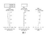
圖2由左至右依序為第一實施例之第一態樣的球差、像散以及畸變曲線圖。Fig. 2 shows the spherical aberration, astigmatism and distortion curves of the first aspect of the first embodiment in order from left to right.
圖3由左至右依序為第一實施例之第二態樣的球差、像散以及畸變曲線圖。Fig. 3 shows the spherical aberration, astigmatism and distortion curves of the second aspect of the first embodiment in order from left to right.
圖4由左至右依序為第一實施例之第三態樣的球差、像散以及畸變曲線圖。Fig. 4 shows the spherical aberration, astigmatism and distortion curves of the third aspect of the first embodiment in order from left to right.
圖5繪示依照本發明第二實施例之第一態樣的取像裝置示意圖。FIG. 5 is a schematic diagram of the image capturing device according to the first aspect of the second embodiment of the present invention.
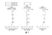
圖6由左至右依序為第二實施例之第一態樣的球差、像散以及畸變曲線圖。Fig. 6 shows the spherical aberration, astigmatism and distortion curves of the first aspect of the second embodiment in order from left to right.
圖7由左至右依序為第二實施例之第二態樣的球差、像散以及畸變曲線圖。FIG. 7 shows the spherical aberration, astigmatism and distortion curves of the second aspect of the second embodiment in order from left to right.
圖8繪示依照本發明第三實施例之第一態樣的取像裝置示意圖。FIG. 8 is a schematic diagram of the image capturing device according to the first aspect of the third embodiment of the present invention.
圖9由左至右依序為第三實施例之第一態樣的球差、像散以及畸變曲線圖。FIG. 9 shows the spherical aberration, astigmatism and distortion curves of the first aspect of the third embodiment in order from left to right.
圖10由左至右依序為第三實施例之第二態樣的球差、像散以及畸變曲線圖。Fig. 10 shows the spherical aberration, astigmatism and distortion curves of the second aspect of the third embodiment in order from left to right.
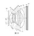
圖11繪示依照本發明第四實施例之第一態樣的取像裝置示意圖。FIG. 11 is a schematic diagram of the image capturing device according to the first aspect of the fourth embodiment of the present invention.
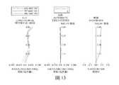
圖12由左至右依序為第四實施例之第一態樣的球差、像散以及畸變曲線圖。Fig. 12 shows the spherical aberration, astigmatism and distortion curves of the first aspect of the fourth embodiment in order from left to right.
圖13由左至右依序為第四實施例之第二態樣的球差、像散以及畸變曲線圖。FIG. 13 shows the spherical aberration, astigmatism and distortion curves of the second aspect of the fourth embodiment in order from left to right.
圖14由左至右依序為第四實施例之第三態樣的球差、像散以及畸變曲線圖。Fig. 14 shows the spherical aberration, astigmatism and distortion curves of the third aspect of the fourth embodiment in order from left to right.
圖15繪示依照本發明第五實施例之第一態樣的取像裝置示意圖。15 is a schematic diagram of the image capturing device according to the first aspect of the fifth embodiment of the present invention.
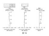
圖16由左至右依序為第五實施例之第一態樣的球差、像散以及畸變曲線圖。Fig. 16 shows the spherical aberration, astigmatism and distortion curves of the first aspect of the fifth embodiment in order from left to right.
圖17由左至右依序為第五實施例之第二態樣的球差、像散以及畸變曲線圖。Fig. 17 shows the spherical aberration, astigmatism and distortion curves of the second aspect of the fifth embodiment in order from left to right.
圖18由左至右依序為第五實施例之第三態樣的球差、像散以及畸變曲線圖。Fig. 18 shows the spherical aberration, astigmatism and distortion curves of the third aspect of the fifth embodiment in order from left to right.
圖19繪示依照本發明第六實施例之第一態樣的取像裝置示意圖。19 is a schematic diagram of an image capturing device according to the first aspect of the sixth embodiment of the present invention.
圖20由左至右依序為第六實施例之第一態樣的球差、像散以及畸變曲線圖。Fig. 20 shows the spherical aberration, astigmatism and distortion curves of the first aspect of the sixth embodiment in order from left to right.
圖21由左至右依序為第六實施例之第二態樣的球差、像散以及畸變曲線圖。Fig. 21 shows the spherical aberration, astigmatism and distortion curves of the second aspect of the sixth embodiment in order from left to right.
圖22由左至右依序為第六實施例之第三態樣的球差、像散以及畸變曲線圖。Fig. 22 shows the spherical aberration, astigmatism and distortion curves of the third aspect of the sixth embodiment in order from left to right.
圖23繪示依照本發明第七實施例之第一態樣的取像裝置示意圖。FIG. 23 is a schematic diagram of the imaging device according to the first aspect of the seventh embodiment of the present invention.
圖24由左至右依序為第七實施例之第一態樣的球差、像散以及畸變曲線圖。Fig. 24 is a graph of spherical aberration, astigmatism and distortion of the first aspect of the seventh embodiment in order from left to right.
圖25由左至右依序為第七實施例之第二態樣的球差、像散以及畸變曲線圖。FIG. 25 shows the spherical aberration, astigmatism, and distortion curves of the second aspect of the seventh embodiment in order from left to right.
圖26繪示依照本發明第八實施例之第一態樣的取像裝置示意圖。FIG. 26 is a schematic diagram of the image capturing device according to the first aspect of the eighth embodiment of the present invention.
圖27由左至右依序為第八實施例之第一態樣的球差、像散以及畸變曲線圖。Fig. 27 is a graph of spherical aberration, astigmatism and distortion of the first aspect of the eighth embodiment in order from left to right.
圖28由左至右依序為第八實施例之第二態樣的球差、像散以及畸變曲線圖。Fig. 28 shows the spherical aberration, astigmatism and distortion curves of the second aspect of the eighth embodiment in order from left to right.
圖29繪示依照本發明第九實施例的一種取像裝置立體示意圖。FIG. 29 is a three-dimensional schematic diagram of an image capturing device according to a ninth embodiment of the present invention.
圖30繪示依照本發明第十實施例的一種電子裝置之一側的立體示意圖。FIG. 30 is a schematic perspective view of one side of an electronic device according to a tenth embodiment of the invention.
圖31繪示圖30之電子裝置之另一側的立體示意圖。FIG. 31 is a schematic perspective view of the other side of the electronic device of FIG. 30.
圖32繪示圖30之電子裝置的系統方塊圖。FIG. 32 is a system block diagram of the electronic device of FIG. 30.
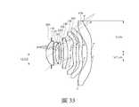
圖33繪示依照本發明第一實施例之第一態樣中參數YLf1f、YLr1r和YCLr1r以及部份透鏡之反曲點和臨界點的示意圖。33 is a schematic diagram of the parameters YLf1f, YLr1r, and YCLr1r and the inflection point and critical point of a part of the lens in the first aspect of the first embodiment of the present invention.
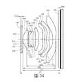
圖34繪示依照本發明第一實施例之第一態樣中參數CTt、TL、SDi、TDi和TLi的示意圖。FIG. 34 is a schematic diagram of the parameters CTt, TL, SDi, TDi, and TLi in the first aspect according to the first embodiment of the present invention.
圖35繪示依照本發明第一實施例之第一態樣中參數CRA的示意圖。35 is a schematic diagram of the parameter CRA in the first aspect according to the first embodiment of the present invention.
圖36繪示第一實施例之可調焦組件為一液態透鏡組的示意圖。FIG. 36 is a schematic diagram of the adjustable focus component of the first embodiment as a liquid lens group.
圖37繪示第一實施例之可調焦組件為另一液態透鏡組的示意圖。FIG. 37 is a schematic diagram of the adjustable focus component of the first embodiment as another liquid lens group.
圖38繪示第一實施例之可調焦組件為一液晶透鏡組的示意圖。FIG. 38 is a schematic diagram showing that the adjustable focus component of the first embodiment is a liquid crystal lens group.
光學成像鏡頭組包含可調焦組件以及成像透鏡系統。本發明所揭露的光學成像鏡頭組可因應不同被攝物的距離或環境的溫度,而達到自動對焦的技術。具體來說,光學成像鏡頭組藉由可調焦組件的作動以調整光學成像鏡頭組的焦距,使欲拍攝的畫面清晰成像於包含光學成像鏡頭組之取像裝置中的電子感光元件上。其中,可調焦組件可為液態透鏡組、液晶透鏡組、正透鏡、負透鏡或任何可達到變焦功能之光學組件,並且液態透鏡組可包含透明基底與液態材料。可調焦組件可藉由外加的控制單元(如電路、壓力等)來改變光學成像鏡頭組的焦距,以達到模組微型化及近距離自動對焦的效果,此外,亦可藉由調整可調焦組件的焦距來達成光學防手震或光學變焦等效果。The optical imaging lens group includes an adjustable focus component and an imaging lens system. The optical imaging lens set disclosed in the present invention can achieve automatic focusing technology according to the distance of different objects or the temperature of the environment. Specifically, the optical imaging lens set adjusts the focal length of the optical imaging lens set through the actuation of the adjustable focus component, so that the image to be shot can be clearly imaged on the electronic photosensitive element in the imaging device including the optical imaging lens set. Among them, the adjustable focus component can be a liquid lens group, a liquid crystal lens group, a positive lens, a negative lens or any optical component that can achieve a zoom function, and the liquid lens group can include a transparent substrate and a liquid material. Adjustable focus components can change the focal length of the optical imaging lens group by additional control units (such as circuits, pressure, etc.) to achieve the effect of miniaturization of the module and close-range autofocus. In addition, it can also be adjusted by adjustment The focal length of the focal component is used to achieve the effects of optical anti-shake or optical zoom.
為了能明確且充分揭露本發明的技術資訊,在以下說明中,成像透鏡系統由物側至像側依序包含第一透鏡組與第二透鏡組,其中第一透鏡組由物側至像側依序包含物側第一透鏡以及物側第二透鏡,第二透鏡組由像側至物側(即,相反於由物側至像側的方向)依序包含像側第一透鏡以及像側第二透鏡,且成像透鏡系統中的所有透鏡分別具有朝向物側方向的物側表面與朝向像側方向的像側表面。其中,第一透鏡組中的透鏡較成像透鏡系統中的其他透鏡靠近物側,且第二透鏡組中的透鏡較成像透鏡系統中的其他透鏡靠近像側。即,第一透鏡組的物側第一透鏡和物側第二透鏡為成像透鏡系統中最靠近物側的二片透鏡,且第二透鏡組的像側第一透鏡和像側第二透鏡為成像透鏡系統中最靠近像側的二片透鏡。In order to clearly and fully disclose the technical information of the present invention, in the following description, the imaging lens system includes a first lens group and a second lens group in order from the object side to the image side, and the first lens group is from the object side to the image side. Including a first lens on the object side and a second lens on the object side in sequence, the second lens group from the image side toThe object side (that is, opposite to the direction from the object side to the image side) sequentially includes an image-side first lens and an image-side second lens, and all the lenses in the imaging lens system respectively have an object-side surface and a The image side surface facing the image side direction. Wherein, the lens in the first lens group is closer to the object side than other lenses in the imaging lens system, and the lens in the second lens group is closer to the image side than other lenses in the imaging lens system. That is, the object side first lens and the object side second lens of the first lens group are the two lenses closest to the object side in the imaging lens system, and the image side first lens and the image side second lens of the second lens group are The two lenses closest to the image side in the imaging lens system.
本發明所揭露的光學成像鏡頭組中,成像透鏡系統中的透鏡總數為至少四片;藉此,可確保成像透鏡系統具有足夠數量的透鏡以修正像差,以提供高成像品質。其中,成像透鏡系統中的透鏡總數亦可為至少六片;藉此,有助於進一步修正像差,以提供更佳的成像品質。其中,成像透鏡系統中的透鏡總數亦可為至少七片。In the optical imaging lens set disclosed in the present invention, the total number of lenses in the imaging lens system is at least four; thereby, it can be ensured that the imaging lens system has a sufficient number of lenses to correct aberrations and provide high imaging quality. Among them, the total number of lenses in the imaging lens system can also be at least six; thereby, it is helpful to further correct aberrations and provide better imaging quality. The total number of lenses in the imaging lens system can also be at least seven.
物側第一透鏡可具有正屈折力;藉此,有助於壓縮成像透鏡系統的體積。物側第一透鏡物側表面於近光軸處可為凸面;藉此,可讓光線均勻地進入成像透鏡系統。物側第一透鏡像側表面於近光軸處可為凹面;藉此,可調整光線的行進方向,有助於修正像散等像差。The first lens on the object side may have a positive refractive power; thereby, it helps to compress the volume of the imaging lens system. The object-side surface of the object-side first lens can be convex at the near optical axis; thereby, light can enter the imaging lens system uniformly. The image side surface of the first lens on the object side can be concave at the near optical axis; thereby, the traveling direction of the light can be adjusted, which helps correct aberrations such as astigmatism.
物側第二透鏡可具有負屈折力;藉此,可平衡為壓縮體積所產生之球差等像差。物側第二透鏡像側表面於近光軸處可為凹面;藉此,可調整物側第二透鏡的屈折力以修正像差。The object-side second lens can have negative refractive power; thereby, it can balance aberrations such as spherical aberration generated by the compressed volume. The image side surface of the object side second lens can be concave at the near optical axis; thereby, the refractive power of the object side second lens can be adjusted to correct aberrations.
像側第二透鏡可具有正屈折力。藉此,可分擔壓縮體積所需的正屈折力,以降低單一透鏡所產生的敏感度。The second lens on the image side may have a positive refractive power. In this way, the positive refractive power required to compress the volume can be shared to reduce the sensitivity generated by a single lens.
像側第一透鏡可具有負屈折力;藉此,可平衡成像透鏡系統像側端的屈折力,以修正像差。像側第一透鏡像側表面於近光軸處可為凹面;藉此,可調整像側第一透鏡的屈折力,並能將後焦長度調整在適當範圍內。The image side first lens may have a negative refractive power; thereby, the refractive power of the image side end of the imaging lens system can be balanced to correct aberrations. The image side surface of the image side first lens can be concave at the near optical axis; thereby, the refractive power of the image side first lens can be adjusted, and the back focus length can be adjusted within a proper range.
成像透鏡系統中至少一片透鏡的物側表面與像側表面中至少一表面為非球面且具有至少一反曲點;藉此,可提升透鏡表面的變化程度,以壓縮體積並提升成像品質。其中,成像透鏡系統中亦可有至少二片透鏡各自的物側表面與像側表面中至少一表面為非球面且具有至少一反曲點。其中,成像透鏡系統中亦可有至少三片透鏡各自的物側表面與像側表面中至少一表面為非球面且具有至少一反曲點。其中,成像透鏡系統中亦可有至少四片透鏡各自的物側表面與像側表面中至少一表面為非球面且具有至少一反曲點。其中,成像透鏡系統的第二透鏡組中可有至少一片透鏡的物側表面與像側表面中至少一表面為非球面且具有至少一反曲點;藉此,將反曲點設置於成像透鏡系統的像側端,有助於提升周邊影像品質。其中,第二透鏡組中亦可有至少二片透鏡各自的物側表面與像側表面中至少一表面為非球面且具有至少一反曲點。在一些實施態樣中,成像透鏡系統中的透鏡總數可為五片以上,且第二透鏡組可包含成像透鏡系統中最靠近像側的三片或更多的透鏡。其中,第二透鏡組中亦可有至少三片透鏡各自的物側表面與像側表面中至少一表面為非球面且具有至少一反曲點。其中,第二透鏡組中亦可有至少四片透鏡各自的物側表面與像側表面中至少一表面為非球面且具有至少一反曲點。其中,成像透鏡系統中任一透鏡的物側表面與像側表面可皆為非球面且皆具有至少一反曲點;藉此,可調整透鏡的面形,而有助於進一步修正像差。請參照圖33,係繪示有依照本發明第一實施例之第一態樣中第一透鏡110、第三透鏡130、第四透鏡140、第五透鏡150、第六透鏡160以及第七透鏡170之反曲點P的示意圖,其中第一透鏡110為物側第一透鏡,第二透鏡120為物側第二透鏡,第六透鏡160為像側第二透鏡,且第七透鏡170為像側第一透鏡。At least one of the object-side surface and the image-side surface of at least one lens in the imaging lens system is aspherical and has at least one inflection point; thereby, the degree of change of the lens surface can be increased to suppressReduce volume and improve image quality. Wherein, at least one of the object side surface and the image side surface of each of at least two lenses in the imaging lens system is aspherical and has at least one inflection point. Wherein, at least one of the object side surface and the image side surface of each of at least three lenses in the imaging lens system is aspherical and has at least one inflection point. Wherein, at least one of the object side surface and the image side surface of each of at least four lenses in the imaging lens system is aspherical and has at least one inflection point. Wherein, at least one of the object side surface and the image side surface of at least one lens in the second lens group of the imaging lens system is aspherical and has at least one inflection point; thereby, the inflection point is set on the imaging lens The image side end of the system helps to improve the surrounding image quality. Wherein, at least one of the object side surface and the image side surface of each of at least two lenses in the second lens group is aspherical and has at least one inflection point. In some embodiments, the total number of lenses in the imaging lens system may be five or more, and the second lens group may include three or more lenses closest to the image side in the imaging lens system. Wherein, at least one of the object side surface and the image side surface of each of at least three lenses in the second lens group is aspherical and has at least one inflection point. Wherein, at least one of the object side surface and the image side surface of each of at least four lenses in the second lens group is aspherical and has at least one inflection point. Wherein, the object side surface and the image side surface of any lens in the imaging lens system can both be aspherical and both have at least one inflection point; thereby, the surface shape of the lens can be adjusted, which helps to further correct aberrations. Please refer to FIG. 33, which shows a
成像透鏡系統中可有至少一片透鏡的物側表面與像側表面中至少一表面於離軸處具有至少一臨界點;藉此,可進一步提升透鏡表面的變化程度,以壓縮體積與提升成像面周邊影像品質。其中,成像透鏡系統中亦可有至少二片透鏡各自的物側表面與像側表面中至少一表面於離軸處具有至少一臨界點。其中,成像透鏡系統中亦可有至少三片透鏡各自的物側表面與像側表面中至少一表面於離軸處具有至少一臨界點。其中,成像透鏡系統的第二透鏡組中可有至少一片透鏡的物側表面與像側表面中至少一表面於離軸處具有至少一臨界點;藉此,將臨界點設置於成像透鏡系統的像側端,有助於修正離軸像差與提升成像面周邊影像照度。其中,第二透鏡組中亦可有至少二片透鏡各自的物側表面與像側表面中至少一表面於離軸處具有至少一臨界點。在成像透鏡系統中的透鏡總數為五片以上的實施態樣中,第二透鏡組可包含成像透鏡系統中最靠近像側的三片或更多的透鏡,且第二透鏡組中可有至少三片透鏡各自的物側表面與像側表面中至少一表面於離軸處具有至少一臨界點。其中,像側第二透鏡物側表面與像側第二透鏡像側表面中至少一表面於離軸處可具有至少一臨界點;藉此,有助於修正周邊像差與調整像側端外徑大小。其中,像側第二透鏡物側表面於離軸處可具有至少一臨界點;藉此,可調整周邊光線於像側第二透鏡的入射角度,而有助於降低面反射。其中,像側第一透鏡物側表面於離軸處可具有至少一臨界點;藉此,有助於降低離軸像彎曲等像差。其中,像側第一透鏡像側表面於離軸處可具有至少一凸臨界點;藉此,有助於調整光線於成像面的入射方向,以提升周邊影像照度。其中,成像透鏡系統中任一透鏡的物側表面與像側表面於離軸處可皆具有至少一臨界點;藉此,可調整透鏡的面形,而有助於進一步修正像差與壓縮透鏡外徑。請參照圖33,係繪示有依照本發明第一實施例之第一態樣中第三透鏡130、第四透鏡140、第五透鏡150、第六透鏡160以及第七透鏡170之臨界點C的示意圖。In the imaging lens system, at least one of the object-side surface and the image-side surface of at least one lens has at least one critical point off-axis; thereby, the degree of change of the lens surface can be further increased to compress the volume and improve the imaging surface Surrounding image quality. In the imaging lens system, at least one of the object side surface and the image side surface of each of at least two lenses may have at least one critical point off-axis. Wherein, at least one of the object side surface and the image side surface of each of at least three lenses in the imaging lens system has at least one critical point off-axis. Among them, the second lens group of the imaging lens systemAt least one of the object-side surface and the image-side surface of at least one lens has at least one critical point off-axis; thereby, the critical point is set at the image-side end of the imaging lens system to help correct the off-axis image Improve the image illuminance around the imaging surface. Wherein, at least one of the object side surface and the image side surface of each of at least two lenses in the second lens group has at least one critical point off-axis. In the embodiment where the total number of lenses in the imaging lens system is five or more, the second lens group may include three or more lenses closest to the image side in the imaging lens system, and the second lens group may have at least At least one of the object side surface and the image side surface of each of the three lenses has at least one critical point off-axis. Wherein, at least one of the object-side surface of the second image-side lens and the image-side surface of the second image-side lens may have at least one critical point off-axis; thereby, it is helpful to correct the peripheral aberrations and adjust the image-side external The size of the diameter. Wherein, the object side surface of the second image side lens can have at least one critical point off-axis; thereby, the incident angle of the peripheral light on the second image side lens can be adjusted, which helps reduce surface reflection. Wherein, the object side surface of the image side first lens may have at least one critical point at the off-axis position; thereby, it is helpful to reduce aberrations such as off-axis image curvature. Wherein, the image side surface of the first image side lens may have at least one convex critical point at an off-axis position; thereby, it is helpful to adjust the incident direction of the light on the imaging surface to improve the peripheral image illuminance. Wherein, the object-side surface and the image-side surface of any lens in the imaging lens system may have at least one critical point off-axis; thereby, the surface shape of the lens can be adjusted, which helps to further correct aberrations and compress the lens Outer diameter. Please refer to FIG. 33, which illustrates the critical point C of the
像側第一透鏡與像側第二透鏡於光軸上的間隔距離為DLr1Lr2,像側第一透鏡於光軸上的厚度為CTLr1,其可滿足下列條件:0.60<DLr1Lr2/CTLr1。藉此,可調整成像透鏡系統像側端的透鏡分布,而有助於壓縮總長。其中,亦可滿足下列條件:0.70<DLr1Lr2/CTLr1<5.0。其中,亦可滿足下列條件:0.80<DLr1Lr2/CTLr1<3.0。其中,亦可滿足下列條件:1.0<DLr1Lr2/CTLr1<2.0。The separation distance between the first lens on the image side and the second lens on the image side on the optical axis is DLr1Lr2, and the thickness of the first lens on the image side on the optical axis is CTLr1, which can satisfy the following condition: 0.60<DLr1Lr2/CTLr1. Thereby, the lens distribution at the image side end of the imaging lens system can be adjusted, which helps to reduce the overall length. Among them, the following conditions can also be met: 0.70<DLr1Lr2/CTLr1<5.0. Among them, the following conditions can also be met: 0.80<DLr1Lr2/CTLr1<3.0. Among them, the following conditions can also be met: 1.0<DLr1Lr2/CTLr1<2.0.
像側第二透鏡物側表面的曲率半徑為RLr2f,像側第二透鏡像側表面的曲率半徑為RLr2r,其可滿足下列條件:|RLr2f/RLr2r|<4.5。藉此,可調整像側第二透鏡的面形,而有助於修正像散與離軸像差。其中,亦可滿足下列條件:|RLr2f/RLr2r|<3.0。其中,亦可滿足下列條件:|RLr2f/RLr2r|<1.5。The curvature radius of the object side surface of the second image side lens is RLr2f, and the curvature radius of the image side surface of the second image side lens is RLr2r, which can satisfy the following conditions: |RLr2f/RLr2r|<4.5. With this, adjustableThe surface shape of the second lens on the whole image side helps correct astigmatism and off-axis aberration. Among them, the following conditions can also be met: |RLr2f/RLr2r|<3.0. Among them, the following conditions can also be met: |RLr2f/RLr2r|<1.5.
光學成像鏡頭組的光圈值(F-number)為Fno,其可滿足下列條件:0.80<Fno<3.0。藉此,可讓光學成像鏡頭組具有適當大小的光圈以配合各種應用。其中,亦可滿足下列條件:1.0<Fno<2.5。其中,亦可滿足下列條件:1.2<Fno<2.0。The F-number of the optical imaging lens group is Fno, which can meet the following conditions: 0.80<Fno<3.0. In this way, the optical imaging lens group can have an appropriate aperture to suit various applications. Among them, the following conditions can also be met: 1.0<Fno<2.5. Among them, the following conditions can also be met: 1.2<Fno<2.0.
本發明所揭露的光學成像鏡頭組中,成像透鏡系統中可有至少三片透鏡各自的阿貝數皆小於50.0。藉此,可調整透鏡材質配置,以修正色差等像差。其中,成像透鏡系統中亦可有至少三片透鏡各自的阿貝數皆小於45.0。其中,成像透鏡系統中亦可有至少三片透鏡各自的阿貝數皆小於40.0。In the optical imaging lens set disclosed in the present invention, at least three lenses in the imaging lens system may each have an Abbe number less than 50.0. In this way, the lens material configuration can be adjusted to correct aberrations such as chromatic aberration. Among them, there may be at least three lenses in the imaging lens system each having an Abbe number less than 45.0. Among them, the imaging lens system may also have at least three lenses each having an Abbe number less than 40.0.
光學成像鏡頭組中最大視角的一半為HFOV,其可滿足下列條件:15.0[度]<HFOV<90.0[度];藉此,可調整視角於適當範圍以配合各種應用。其中,亦可滿足下列條件:30.0[度]<HFOV<55.0[度];藉此,可讓光學成像鏡頭組具有廣角的特性,並能避免因視角過大所產生之畸變。其中,亦可滿足下列條件:35.0[度]<HFOV<45.0[度]。Half of the maximum viewing angle in the optical imaging lens group is HFOV, which can meet the following conditions: 15.0[degree]<HFOV<90.0[degree]; thereby, the viewing angle can be adjusted to an appropriate range to suit various applications. Among them, the following conditions can also be met: 30.0[degrees]<HFOV<55.0[degrees]; thereby, the optical imaging lens group can have wide-angle characteristics and avoid distortion caused by excessive viewing angles. Among them, the following conditions can also be met: 35.0[degree]<HFOV<45.0[degree].
光學成像鏡頭組的焦距為f,可調焦組件的焦距為ft,其可滿足下列條件:|f/ft|<0.40。藉此,可調整可調焦組件的屈折力強度,以避免調焦過程產生多餘像差。其中,亦可滿足下列條件:|f/ft|<0.20。其中,亦可滿足下列條件:|f/ft|<0.10。其中,亦可滿足下列條件:|f/ft|<0.05。The focal length of the optical imaging lens group is f, and the focal length of the adjustable focus component is ft, which can meet the following conditions: |f/ft|<0.40. In this way, the refractive strength of the adjustable focus component can be adjusted to avoid unnecessary aberrations during the focusing process. Among them, the following conditions can also be met: |f/ft|<0.20. Among them, the following conditions can also be met: |f/ft|<0.10. Among them, the following conditions can also be met: |f/ft|<0.05.
可調焦組件於光軸上的厚度為CTt,其可滿足下列條件:0.10[公釐]<CTt<1.00[公釐]。藉此,可調整可調焦組件的厚度,以避免占用過多空間並確保可調焦程度。其中,亦可滿足下列條件:0.15[公釐]<CTt<0.85[公釐]。請參照圖34,係繪示有依照本發明第一實施例之第一態樣中參數CTt的示意圖。The thickness of the adjustable focus component on the optical axis is CTt, which can meet the following conditions: 0.10[mm]<CTt<1.00[mm]. In this way, the thickness of the focus adjustable component can be adjusted to avoid occupying too much space and ensure the degree of focus adjustment. Among them, the following conditions can also be met: 0.15[mm]<CTt<0.85[mm]. Please refer to FIG. 34, which shows a schematic diagram of the parameter CTt in the first aspect according to the first embodiment of the present invention.
像側第一透鏡像側表面的曲率半徑為RLr1r,光學成像鏡頭組的最大成像高度為ImgH(即電子感光元件之有效感測區域對角線總長的一半),其可滿足下列條件:RLr1r/ImgH<1.0。藉此,可調整光線於成像面的入射角,以配合電子感光元件並提升照度。The curvature radius of the image side surface of the first lens on the image side is RLr1r, and the maximum imaging height of the optical imaging lens group is ImgH (that is, half of the total diagonal length of the effective sensing area of the electronic photosensitive element), which can meet the following conditions: RLr1r/ ImgH<1.0. In this way, the incident angle of light on the imaging surface can be adjusted toCooperate with electronic photosensitive element and enhance the illuminance.
光學成像鏡頭組於最大成像高度位置的主光線入射角度為CRA,其可滿足下列條件:25.0[度]<CRA<50.0[度]。藉此,可調整光線於成像面的入射角,以提升電子感光元件的響應效率。其中,亦可滿足下列條件:30.0[度]<CRA<45.0[度]。請參照圖35,係繪示有依照本發明第一實施例之第一態樣中參數CRA的示意圖,其中有一主光線CR入射於成像面195的最大成像高度之位置,且成像面195的法線方向與主光線CR之間的夾角即為CRA。The chief ray incident angle of the optical imaging lens group at the maximum imaging height position is CRA, which can meet the following conditions: 25.0[degrees]<CRA<50.0[degrees]. Thereby, the incident angle of light on the imaging surface can be adjusted to improve the response efficiency of the electronic photosensitive element. Among them, the following conditions can also be met: 30.0[degree]<CRA<45.0[degree]. Please refer to FIG. 35, which shows a schematic diagram of the parameter CRA in the first aspect according to the first embodiment of the present invention, in which a chief ray CR is incident on the position of the maximum imaging height of the
可調焦組件物側表面至成像面於光軸上的距離為TL,其可滿足下列條件:3.50[公釐]<TL<10.00[公釐]。藉此,可使光學成像鏡頭組的總長於適當範圍內以配合各種應用。請參照圖34,係繪示有依照本發明第一實施例之第一態樣中參數TL的示意圖。The distance from the object side surface of the adjustable focus component to the imaging surface on the optical axis is TL, which can meet the following conditions: 3.50[mm]<TL<10.00[mm]. Thereby, the total length of the optical imaging lens group can be made within a proper range to suit various applications. Please refer to FIG. 34, which shows a schematic diagram of the parameter TL in the first aspect according to the first embodiment of the present invention.
本發明所揭露的光學成像鏡頭組中,可調焦組件可位於成像透鏡系統的物側方向,亦即可調焦組件可位於被攝物及成像透鏡系統之間。藉此,可提升光學成像鏡頭組的組裝便利性。In the optical imaging lens assembly disclosed in the present invention, the focusing component can be located in the object side direction of the imaging lens system, that is, the focusing component can be located between the object and the imaging lens system. Thereby, the assembly convenience of the optical imaging lens group can be improved.
本發明所揭露的光學成像鏡頭組更包含一光圈,且光圈可設置於物側第一透鏡與被攝物之間。藉此,有助於壓縮光學成像鏡頭組的總長與調整視角。The optical imaging lens set disclosed in the present invention further includes an aperture, and the aperture can be set between the first lens on the object side and the object. This helps to compress the total length of the optical imaging lens group and adjust the viewing angle.
光圈至像側第一透鏡像側表面於光軸上的距離為SDi,物側第一透鏡物側表面至像側第一透鏡像側表面於光軸上的距離為TDi,其可滿足下列條件:0.60<SDi/TDi<1.1。藉此,可調整光圈位置,以在總長與視角間取得平衡。其中,亦可滿足下列條件:0.80<SDi/TDi<1.0。請參照圖34,係繪示有依照本發明第一實施例之第一態樣中參數SDi及TDi的示意圖。The distance on the optical axis from the aperture to the image side surface of the first lens on the image side is SDi, and the distance on the optical axis from the object side surface of the first lens on the object side to the image side surface of the first lens on the image side is TDi, which can meet the following conditions : 0.60<SDi/TDi<1.1. In this way, the position of the aperture can be adjusted to achieve a balance between the total length and the viewing angle. Among them, the following conditions can also be met: 0.80<SDi/TDi<1.0. Please refer to FIG. 34, which shows a schematic diagram of the parameters SDi and TDi in the first aspect according to the first embodiment of the present invention.
成像透鏡系統的焦距為fi,可調焦組件的焦距為ft,其可滿足下列條件:|fi/ft|<1.00;藉此,可調整可調焦組件與成像透鏡系統的屈折力配置,而有助於降低敏感度與達成微型化。其中,亦可滿足下列條件:|fi/ft|<0.25;藉此,可降低調焦過程中所產生之像差。其中,亦可滿足下列條件:|fi/ft|<0.10。其中,亦可滿足下列條件:|fi/ft|<0.05。The focal length of the imaging lens system is fi, and the focal length of the adjustable focus assembly is ft, which can meet the following conditions: |fi/ft|<1.00; thereby, the refractive power configuration of the adjustable focus assembly and the imaging lens system can be adjusted, and Help reduce sensitivity and achieve miniaturization. Among them, the following conditions can also be met: |fi/ft|<0.25; thereby, the aberrations generated in the focusing process can be reduced. Among them, the following conditions can also be met: |fi/ft|<0.10.Among them, the following conditions can also be met: |fi/ft|<0.05.
可調焦組件的焦距為ft,其可滿足下列條件:15.0[公釐]<|ft|。藉此,可避免可調焦組件的屈折力過強,以降低敏感度與減少像差。其中,亦可滿足下列條件:25.0[公釐]<|ft|。其中,亦可滿足下列條件:40.0[公釐]<|ft|。其中,亦可滿足下列條件:80.0[公釐]<|ft|。The focal length of the adjustable focus component is ft, which can meet the following conditions: 15.0[mm]<|ft|. In this way, the refractive power of the adjustable focus component can be prevented from being too strong, so as to reduce sensitivity and reduce aberrations. Among them, the following conditions can also be met: 25.0[mm]<|ft|. Among them, the following conditions can also be met: 40.0[mm]<|ft|. Among them, the following conditions can also be met: 80.0[mm]<|ft|.
像側第一透鏡像側表面的臨界點與光軸間的垂直距離為YCLr1r,物側第一透鏡物側表面至像側第一透鏡像側表面於光軸上的距離為TDi,像側第一透鏡像側表面於離軸處可具有至少一凸臨界點其滿足下列條件:0.10<YCLr1r/TDi<0.50。藉此,可調整臨界點位置與透鏡配置,以進一步壓縮體積。請參照圖33及圖34,其中圖33係繪示有依照本發明第一實施例之第一態樣中參數YCLr1r的示意圖,且圖34係繪示有依照本發明第一實施例之第一態樣中參數TDi的示意圖。The vertical distance between the critical point of the image side surface of the first lens on the image side and the optical axis is YCLr1r, the distance on the optical axis from the object side surface of the first lens on the object side to the image side surface of the first lens on the image side is TDi, and the image side The image side surface of a lens may have at least one convex critical point at the off-axis position, which satisfies the following condition: 0.10<YCLr1r/TDi<0.50. In this way, the critical point position and lens configuration can be adjusted to further compress the volume. Please refer to FIG. 33 and FIG. 34, in which FIG. 33 shows a schematic diagram of the parameter YCLr1r in the first aspect according to the first embodiment of the present invention, and FIG. 34 shows the first embodiment according to the first embodiment of the present invention. Schematic diagram of the parameter TDi in the aspect.
物側第一透鏡物側表面至成像面於光軸上的距離為TLi,成像透鏡系統的焦距為fi,其可滿足下列條件:0.50<TLi/fi<2.0。藉此,可讓成像透鏡系統在總長與視角間取得平衡。其中,亦可滿足下列條件:1.0<TLi/fi<1.5。請參照圖34,係繪示有依照本發明第一實施例之第一態樣中參數TLi的示意圖。The distance from the object side surface of the first lens on the object side to the imaging surface on the optical axis is TLi, and the focal length of the imaging lens system is fi, which can meet the following conditions: 0.50<TLi/fi<2.0. In this way, the imaging lens system can achieve a balance between the total length and the viewing angle. Among them, the following conditions can also be met: 1.0<TLi/fi<1.5. Please refer to FIG. 34, which shows a schematic diagram of the parameter TLi in the first aspect according to the first embodiment of the present invention.
成像透鏡系統中各二相鄰透鏡於光軸上之間隔距離的總和為ΣATi,成像透鏡系統中各透鏡於光軸上之透鏡厚度的總和為ΣCTi,其可滿足下列條件:0.10<ΣATi/ΣCTi<1.0。藉此,可調整透鏡配置,而有助於壓縮體積。其中,亦可滿足下列條件:0.15<ΣATi/ΣCTi<0.90。The sum of the distances between the two adjacent lenses on the optical axis in the imaging lens system is ΣATi, and the sum of the lens thickness of each lens in the imaging lens system on the optical axis is ΣCTi, which can meet the following conditions: 0.10<ΣATi/ΣCTi <1.0. In this way, the lens configuration can be adjusted and the volume can be reduced. Among them, the following conditions can also be met: 0.15<ΣATi/ΣCTi<0.90.
可調焦組件物側表面至成像面於光軸上的距離為TL,光學成像鏡頭組的最大成像高度為ImgH,其可滿足下列條件:1.0<TL/ImgH<2.0。藉此,可在壓縮總長與增大成像面間取得平衡。The distance from the object side surface of the adjustable focus component to the imaging surface on the optical axis is TL, and the maximum imaging height of the optical imaging lens group is ImgH, which can meet the following conditions: 1.0<TL/ImgH<2.0. In this way, a balance can be achieved between compressing the total length and increasing the imaging surface.
成像透鏡系統的所有透鏡折射率中的最大值為Nimax,其可滿足下列條件:1.66<Nimax<1.75。藉此,使用高折射率材質可進一步壓縮體積與修正像差。The maximum value of all lens refractive indices of the imaging lens system is Nimax, which can satisfy the following condition: 1.66<Nimax<1.75. In this way, the use of high refractive index materials can further compress the volume and correct aberrations.
成像透鏡系統的所有透鏡阿貝數中的最小值為Vimin,其可滿足下列條件:10.0<Vimin<20.0。藉此,使用低阿貝數的材質可修正色差等像差。The minimum Abbe number of all lenses of the imaging lens system is Vimin, which can meet the following conditions: 10.0<Vimin<20.0. In this way, aberrations such as chromatic aberration can be corrected by using a material with a low Abbe number.
物側第一透鏡物側表面至像側第一透鏡像側表面於光軸上的距離為TDi,可調焦組件於光軸上的厚度為CTt,其可滿足下列條件:3.00<TDi/CTt<45.0。藉此,可調整可調焦組件與成像透鏡系統的分布以壓縮光學成像鏡頭組體積。其中,亦可滿足下列條件:5.00<TDi/CTt<30.0。其中,亦可滿足下列條件:7.00<TDi/CTt<20.0。The distance from the object side surface of the first lens on the object side to the image side surface of the first lens on the image side on the optical axis is TDi, and the thickness of the adjustable focus component on the optical axis is CTt, which can meet the following conditions: 3.00<TDi/CTt <45.0. Thereby, the distribution of the adjustable focus component and the imaging lens system can be adjusted to compress the volume of the optical imaging lens group. Among them, the following conditions can also be met: 5.00<TDi/CTt<30.0. Among them, the following conditions can also be met: 7.00<TDi/CTt<20.0.
光學成像鏡頭組的焦距為f,可調焦組件的焦距為ft,被攝物至光學成像鏡頭組最靠近物側的表面於光軸上的距離為TOB,其可滿足下列條件:|f/TOB-f/ft|<1.00E-1。藉此,可調整物距與可調焦組件的屈折力變化,而有助於使調焦過程更加穩定。其中,亦可滿足下列條件:|f/TOB-f/ft|<5.00E-2。其中,亦可滿足下列條件:|f/TOB-f/ft|<1.00E-2。The focal length of the optical imaging lens group is f, the focal length of the adjustable focus assembly is ft, and the distance from the subject to the surface of the optical imaging lens group closest to the object on the optical axis is TOB, which can meet the following conditions: |f/ TOB-f/ft|<1.00E-1. In this way, the object distance can be adjusted and the refractive power of the adjustable focus component changes, which helps to make the focusing process more stable. Among them, the following conditions can also be met: |f/TOB-f/ft|<5.00E-2. Among them, the following conditions can also be met: |f/TOB-f/ft|<1.00E-2.
物側第一透鏡物側表面至成像面於光軸上的距離為TLi,成像透鏡系統的入瞳孔徑為EPDi,其可滿足下列條件:1.0<TLi/EPDi<3.0。藉此,可在體積與光圈大小間取得平衡。The distance from the object side surface of the first lens on the object side to the imaging surface on the optical axis is TLi, and the entrance pupil aperture of the imaging lens system is EPDi, which can meet the following conditions: 1.0<TLi/EPDi<3.0. In this way, a balance can be achieved between volume and aperture size.
成像透鏡系統的焦距為fi,成像透鏡系統中由物側往像側數來第七片透鏡(即,物側第七透鏡)的焦距為fLf7,其可滿足下列條件:0.40<|fi/fLf7|<1.50。藉此,可調整物側第七透鏡的屈折力,而有助於修正像差。舉例來說,當成像透鏡系統中的透鏡總數為七片時,物側第七透鏡即為像側第一透鏡。當成像透鏡系統中的透鏡總數為八片時,物側第七透鏡即為像側第二透鏡,以此類推。The focal length of the imaging lens system is fi, and the focal length of the seventh lens in the imaging lens system counted from the object side to the image side (ie, the seventh lens on the object side) is fLf7, which can meet the following conditions: 0.40<|fi/fLf7 |<1.50. Thereby, the refractive power of the seventh lens on the object side can be adjusted, which helps correct aberrations. For example, when the total number of lenses in the imaging lens system is seven, the seventh lens on the object side is the first lens on the image side. When the total number of lenses in the imaging lens system is eight, the seventh lens on the object side is the second lens on the image side, and so on.
成像透鏡系統中由物側往像側數來第七片透鏡其像側表面(即,物側第七透鏡像側表面)的最大有效半徑為YLf7r,物側第一透鏡物側表面與物側第七透鏡像側表面於光軸上的距離為DLf1fLf7r,其可滿足下列條件:0.50<YLf7r/DLf1fLf7r<0.95。藉此,可調整成像透鏡系統物側第一透鏡至物側第七透鏡間的體積分布,使光學成像鏡頭組有適當大小的體積、光圈與視角。In the imaging lens system, the seventh lens is counted from the object side to the image side. The maximum effective radius of the image side surface (ie, the image side surface of the seventh lens on the object side) is YLf7r, the object side surface of the first lens and the object side The distance of the image side surface of the seventh lens on the optical axis is DLf1fLf7r, which can satisfy the following conditions: 0.50<YLf7r/DLf1fLf7r<0.95. Thereby, the volume distribution between the first lens on the object side and the seventh lens on the object side of the imaging lens system can be adjusted, so that the optical imaging lens group has an appropriate size, aperture, and viewing angle.
物側第一透鏡物側表面的最大有效半徑為YLf1f,像側第一透鏡像側表面的最大有效半徑為YLr1r,其可滿足下列條件:1.50<YLr1r/YLf1f<5.00。藉此,可調整成像透鏡系統的外徑以達成合適的體積分布。其中,亦可滿足下列條件:1.80<YLr1r/YLf1f<3.50。請參照圖33,係繪示有依照本發明第一實施例之第一態樣中參數YLf1f和YLr1r的示意圖。The maximum effective radius of the object side surface of the object side first lens is YLf1f, and the maximum effective radius of the image side surface of the image side first lens is YLr1r, which can satisfy the following conditions: 1.50<YLr1r/YLf1f<5.00. Thereby, the outer diameter of the imaging lens system can be adjusted to achieve a proper volume distribution. Among them, the following conditions can also be met: 1.80<YLr1r/YLf1f<3.50. Please refer to FIG. 33, which shows a schematic diagram of the parameters YLf1f and YLr1r in the first aspect of the first embodiment of the present invention.
上述本發明光學成像鏡頭組中的各技術特徵皆可組合配置,而達到對應之功效。The above-mentioned technical features in the optical imaging lens set of the present invention can be combined and configured to achieve corresponding effects.
本發明揭露的光學成像鏡頭組中,透鏡的材質可為玻璃或塑膠。若透鏡的材質為玻璃,則可增加成像透鏡系統屈折力配置的自由度,而玻璃透鏡可使用研磨或模造等技術製作而成。若透鏡材質為塑膠,則可以有效降低生產成本。此外,可於鏡面上設置非球面(ASP),藉此獲得較多的控制變數,用以消減像差、縮減透鏡數目,並可有效降低本發明光學成像鏡頭組的總長,而非球面可以塑膠射出成型或模造玻璃透鏡等方式製作而成。In the optical imaging lens set disclosed in the present invention, the material of the lens can be glass or plastic. If the material of the lens is glass, the degree of freedom in the configuration of the refractive power of the imaging lens system can be increased, and the glass lens can be manufactured using techniques such as grinding or molding. If the lens material is plastic, the production cost can be effectively reduced. In addition, an aspheric surface (ASP) can be provided on the mirror surface to obtain more control variables to reduce aberrations, reduce the number of lenses, and effectively reduce the total length of the optical imaging lens set of the present invention. The aspheric surface can be made of plastic It is made by injection molding or glass lens molding.
本發明揭露的光學成像鏡頭組中,若透鏡表面為非球面,則表示該透鏡表面光學有效區全部或其中一部分為非球面。In the optical imaging lens set disclosed in the present invention, if the lens surface is aspheric, it means that all or part of the optical effective area of the lens surface is aspheric.
本發明揭露的光學成像鏡頭組中,可選擇性地在任一(以上)透鏡材料中加入添加物,以改變透鏡對於特定波段光線的穿透率,進而減少雜散光與色偏。例如:添加物可具備濾除系統中600奈米至800奈米波段光線的功能,以助於減少多餘的紅光或紅外光;或可濾除350奈米至450奈米波段光線,以減少多餘的藍光或紫外光,因此,添加物可避免特定波段光線對成像造成干擾。此外,添加物可均勻混和於塑料中,並以射出成型技術製作成透鏡。In the optical imaging lens set disclosed in the present invention, additives can be selectively added to any (above) lens material to change the lens's transmittance of light in a specific wavelength band, thereby reducing stray light and color shift. For example: Additives can filter the 600nm to 800nm wavelength light in the system to help reduce excess red or infrared light; or they can filter 350nm to 450nm wavelength light to reduce Excess blue or ultraviolet light, therefore, additives can avoid interference of specific wavelengths of light on imaging. In addition, the additives can be uniformly mixed in the plastic and made into a lens by injection molding technology.
本發明揭露的光學成像鏡頭組中,若透鏡表面係為凸面且未界定該凸面位置時,則表示該凸面可位於透鏡表面近光軸處;若透鏡表面係為凹面且未界定該凹面位置時,則表示該凹面可位於透鏡表面近光軸處。若透鏡之屈折力或焦距未界定其區域位置時,則表示該透鏡之屈折力或焦距可為透鏡於近光軸處之屈折力或焦距。In the optical imaging lens set disclosed in the present invention, if the lens surface is convex and the position of the convex surface is not defined, it means that the convex surface can be located near the optical axis of the lens surface; if the lens surface is concave and the position of the concave surface is not defined , It means that the concave surface can be located near the optical axis of the lens surface. If the refractive power or focal length of a lens does not define its regional position, it means that the refractive power or focal length of the lens can be the refractive power or focal length of the lens at the near optical axis.
本發明揭露的光學成像鏡頭組中,所述透鏡表面的反曲點(Inflection Point),係指透鏡表面曲率正負變化的交界點。所述透鏡表面的臨界點(Critical Point),係指垂直於光軸的平面與透鏡表面相切之切線上的切點,且臨界點並非位於光軸上。In the optical imaging lens set disclosed in the present invention, the inflection point of the lens surface refers to the boundary point where the curvature of the lens surface changes positively and negatively. The critical point of the lens surface refers to the tangent point on the tangent line between the plane perpendicular to the optical axis and the lens surface, and the critical point is not located on the optical axis.
本發明揭露的光學成像鏡頭組中,光學成像鏡頭組之成像面依其對應的電子感光元件之不同,可為一平面或有任一曲率之曲面,特別是指凹面朝往物側方向之曲面。In the optical imaging lens set disclosed in the present invention, the imaging surface of the optical imaging lens set can be a flat surface or a curved surface with any curvature depending on the corresponding electronic photosensitive element, especially a curved surface with a concave surface facing the object side .
本發明揭露的光學成像鏡頭組中,最靠近成像面的透鏡與成像面之間可選擇性配置一片以上的成像修正元件(平場元件等),以達到修正影像的效果(像彎曲等)。該成像修正元件的光學性質,比如曲率、厚度、折射率、位置、面型(凸面或凹面、球面或非球面、繞射表面及菲涅爾表面等)可配合取像裝置需求而做調整。一般而言,較佳的成像修正元件配置為將具有朝往物側方向為凹面的薄型平凹元件設置於靠近成像面處。In the optical imaging lens set disclosed in the present invention, more than one imaging correction element (flat field element, etc.) can be selectively arranged between the lens closest to the imaging surface and the imaging surface to achieve the effect of correcting the image (image curvature, etc.). The optical properties of the imaging correction element, such as curvature, thickness, refractive index, position, surface shape (convex or concave, spherical or aspherical, diffractive surface, and Fresnel surface, etc.) can be adjusted according to the requirements of the imaging device. Generally speaking, a preferred configuration of the imaging correction element is to arrange a thin plano-concave element with a concave surface toward the object side close to the imaging surface.
本發明揭露的光學成像鏡頭組中,可設置有至少一光闌,其可位於物側第一透鏡之前、各透鏡之間或像側第一透鏡之後,該光闌的種類如耀光光闌(Glare Stop)或視場光闌(Field Stop)等,可用以減少雜散光,有助於提升影像品質。The optical imaging lens set disclosed in the present invention may be provided with at least one diaphragm, which may be located before the first lens on the object side, between the lenses, or behind the first lens on the image side. The type of the diaphragm is like a flare diaphragm. (Glare Stop) or Field Stop (Field Stop) can be used to reduce stray light and help improve image quality.
本發明揭露的光學成像鏡頭組中,光圈之配置可為前置光圈或中置光圈。其中前置光圈意即光圈設置於被攝物與物側第一透鏡間,中置光圈則表示光圈設置於物側第一透鏡與成像面間。若光圈為前置光圈,可使出射瞳(Exit Pupil)與成像面產生較長的距離,使其具有遠心(Telecentric)效果,並可增加電子感光元件的CCD或CMOS接收影像的效率;若為中置光圈,係有助於擴大光學成像鏡頭組的視場角。In the optical imaging lens set disclosed in the present invention, the configuration of the aperture can be a front aperture or a middle aperture. The front aperture means that the aperture is set between the object and the first lens on the object side, and the middle aperture means that the aperture is set between the first lens on the object side and the imaging surface. If the aperture is the front aperture, it can make the exit pupil (Exit Pupil) and the imaging surface have a longer distance, making it have a telecentric effect, and can increase the efficiency of the CCD or CMOS of the electronic photosensitive element to receive images; The central aperture helps to expand the field of view of the optical imaging lens group.
本發明可適當設置一可變孔徑元件,該可變孔徑元件可為機械構件或光線調控元件,其可以電或電訊號控制孔徑的尺寸與形狀。該機械構件可包含葉片組、屏蔽板等可動件;該光線調控元件可包含紅外線濾除濾光元件、電致變色材料、液晶層等遮蔽材料。該可變孔徑元件可藉由控制影像的進光量或曝光時間,強化影像調節的能力。此外,該可變孔徑元件亦可為本發明之光圈,可藉由改變光圈值以調節影像品質,如景深或曝光速度等。In the present invention, a variable aperture element can be appropriately provided. The variable aperture element can be a mechanical component or a light control element, which can control the size and shape of the aperture by electrical or electrical signals. The mechanical component may include movable parts such as a blade group and a shielding plate; the light control element may include an infrared filter element,Electrochromic materials, liquid crystal layer and other shielding materials. The variable aperture element can enhance the ability of image adjustment by controlling the amount of light input or exposure time of the image. In addition, the variable aperture element can also be the aperture of the present invention, and the image quality, such as depth of field or exposure speed, can be adjusted by changing the aperture value.
根據上述實施方式,以下提出具體實施例並配合圖式予以詳細說明。According to the above-mentioned embodiments, specific examples are presented below and described in detail in conjunction with the drawings.
<第一實施例><First embodiment>
請參照圖1至圖4,其中圖1繪示依照本發明第一實施例之第一態樣的取像裝置示意圖,圖2由左至右依序為第一實施例之第一態樣的球差、像散以及畸變曲線圖,圖3由左至右依序為第一實施例之第二態樣的球差、像散以及畸變曲線圖,且圖4由左至右依序為第一實施例之第三態樣的球差、像散以及畸變曲線圖。由圖1可知,取像裝置包含光學成像鏡頭組(未另標號)與電子感光元件199。光學成像鏡頭組包含可調焦組件190、光圈100、成像透鏡系統(未另標號)、光闌101、光闌102、濾光元件(Filter)193與成像面195,其中成像透鏡系統包含第一透鏡110、第二透鏡120、第三透鏡130、第四透鏡140、第五透鏡150、第六透鏡160與第七透鏡170。進一步地,上述光學成像鏡頭組中的元件由物側至像側依序為可調焦組件190、光圈100、第一透鏡110、第二透鏡120、光闌101、第三透鏡130、光闌102、第四透鏡140、第五透鏡150、第六透鏡160、第七透鏡170、濾光元件193與成像面195。其中,成像透鏡系統具有第一透鏡組與第二透鏡組的配置。詳細來說,成像透鏡系統由物側至像側依序包含第一透鏡組與第二透鏡組,其中第一透鏡組由物側至像側依序包含物側第一透鏡(第一透鏡110)以及物側第二透鏡(第二透鏡120),且第二透鏡組由像側至物側依序包含像側第一透鏡(第七透鏡170)以及像側第二透鏡(第六透鏡160)。電子感光元件199設置於成像面195上。成像透鏡系統的七片透鏡(110、120、130、140、150、160、170)之間無其他內插的透鏡。Please refer to FIGS. 1 to 4, in which FIG. 1 is a schematic diagram of the first aspect of the imaging device according to the first embodiment of the present invention, and FIG. 2 is the first aspect of the first embodiment in order from left to right Curves of spherical aberration, astigmatism, and distortion. Fig. 3 shows the curves of spherical aberration, astigmatism, and distortion of the second aspect of the first embodiment in order from left to right, and Fig. 4 shows the curves of spherical aberration, astigmatism, and distortion in order from left to right. A graph of spherical aberration, astigmatism, and distortion in the third aspect of an embodiment. It can be seen from FIG. 1 that the image capturing device includes an optical imaging lens set (not marked separately) and an electronic
第一透鏡110具有正屈折力,且為塑膠材質,其物側表面111於近光軸處為凸面,其像側表面112於近光軸處為凹面,其兩表面皆為非球面,其物側表面111具有至少一反曲點,且其像側表面112具有至少一反曲點。The
第二透鏡120具有負屈折力,且為塑膠材質,其物側表面121於近光軸處為凸面,其像側表面122於近光軸處為凹面,其兩表面皆為非球面。The
第三透鏡130具有負屈折力,且為塑膠材質,其物側表面131於近光軸處為凸面,其像側表面132於近光軸處為凹面,其兩表面皆為非球面,其物側表面131具有至少一反曲點,其像側表面132具有至少一反曲點,其物側表面131於離軸處具有至少一臨界點,且其像側表面132於離軸處具有至少一臨界點。The
第四透鏡140具有正屈折力,且為塑膠材質,其物側表面141於近光軸處為凹面,其像側表面142於近光軸處為凸面,其兩表面皆為非球面,其物側表面141具有至少一反曲點,其像側表面142具有至少一反曲點,其物側表面141於離軸處具有至少一臨界點,且其像側表面142於離軸處具有至少一臨界點。The
第五透鏡150具有正屈折力,且為塑膠材質,其物側表面151於近光軸處為凸面,其像側表面152於近光軸處為凹面,其兩表面皆為非球面,其物側表面151具有至少一反曲點,其像側表面152具有至少一反曲點,其物側表面151於離軸處具有至少一臨界點,且其像側表面152於離軸處具有至少一臨界點。The
第六透鏡160具有正屈折力,且為塑膠材質,其物側表面161於近光軸處為凸面,其像側表面162於近光軸處為凹面,其兩表面皆為非球面,其物側表面161具有至少一反曲點,其像側表面162具有至少一反曲點,其物側表面161於離軸處具有至少一臨界點,且其像側表面162於離軸處具有至少一臨界點。The
第七透鏡170具有負屈折力,且為塑膠材質,其物側表面171於近光軸處為凹面,其像側表面172於近光軸處為凹面,其兩表面皆為非球面,其物側表面171具有至少一反曲點,其像側表面172具有至少一反曲點,其物側表面171於離軸處具有至少一臨界點,且其像側表面172於離軸處具有至少一臨界點。The
濾光元件193的材質為玻璃,其設置於第七透鏡170及成像面195之間,並不影響光學成像鏡頭組的焦距。The
可調焦組件190設置於成像透鏡系統的物側方向,用以因應不同被攝物的距離或環境的溫度來改變焦距,進而調整光學成像鏡頭組的焦距。在本實施例中,可調焦組件190可為液態透鏡組、液晶透鏡組、正透鏡、負透鏡或任何可達到變焦功能之光學組件,並可藉由外加的控制單元(如電路、壓力等)來改變光學成像鏡頭組的焦距。詳細來說,請參照圖36、圖37和圖38,其中圖36係繪示第一實施例之可調焦組件為一液態透鏡組的示意圖,圖37係繪示第一實施例之可調焦組件為另一液態透鏡組的示意圖,且圖38係繪示第一實施例之可調焦組件為一液晶透鏡組的示意圖。圖36中可調焦組件190為液態透鏡組,其包含透明基底190a、液態材料190b、可撓式薄膜190c以及壓電材料190d,其中透明基底190a可為玻璃或塑膠等材質,液態材料190b填充於透明基底190a與可撓式薄膜190c之間,且可撓式薄膜190c與壓電材料190d連接。當施加電壓於壓電材料190d時,造成可撓式薄膜190c發生形變,使可調焦組件190的焦距改變,進而調整光學成像鏡頭組的焦距。圖37中可調焦組件190為另一液態透鏡組,其包含透明基底190e、第一液態材料190f、第二液態材料190g以及控制電路190h,其中第一液態材料190f及第二液態材料190g填充於透明基底190e中且互不相溶。當施加電壓時,造成第一液態材料190f及第二液態材料190g接觸面形狀改變,使可調焦組件190的焦距改變,進而調整光學成像鏡頭組的焦距。圖38中可調焦組件190為液晶透鏡組,其包含二液晶透鏡190i、190j以及二控制電路190k、190m,其中液晶透鏡190i、190j各包含透明基底(未另標號)及填充於其中的液晶材料(未另標號),且液晶透鏡190i、190j彼此連接並分別與控制電路190k、190m連接。當施加電壓時,造成液晶透鏡190i、190j的焦距改變,進而調整可調焦組件190的焦距。The
上述各透鏡的非球面的曲線方程式表示如下:
X:非球面上距離光軸為Y的點,其與相切於非球面光軸上交點的切面的相對距離;Y:非球面曲線上的點與光軸的垂直距離;R:曲率半徑;k:錐面係數;以及Ai:第i階非球面係數。X: the point on the aspheric surface from the optical axis Y, the relative distance between it and the tangent plane tangent to the intersection on the aspheric optical axis; Y: the vertical distance between the point on the aspheric curve and the optical axis; R: the radius of curvature; k: cone coefficient; and Ai: aspheric coefficient of order i.
第一實施例的光學成像鏡頭組中,光學成像鏡頭組的焦距為f,光學成像鏡頭組的光圈值為Fno,光學成像鏡頭組中最大視角的一半為HFOV,被攝物至光學成像鏡頭組最靠近物側的表面於光軸上的距離為TOB,可調焦組件190於光軸上的厚度為CTt,可調焦組件190的焦距為ft,且成像透鏡系統的焦距為fi。根據對焦條件的不同,上述部份光學參數的數值亦有所不同,其中,本實施例的光學成像鏡頭組依對焦條件的不同揭露其中三種態樣。In the optical imaging lens group of the first embodiment, the focal length of the optical imaging lens group is f, the aperture value of the optical imaging lens group is Fno, half of the maximum angle of view in the optical imaging lens group is HFOV, and the subject is to the optical imaging lens group The distance on the optical axis of the surface closest to the object side is TOB, the thickness of the
光學成像鏡頭組的第一態樣中:f=6.80公釐(mm),Fno=1.93,HFOV=41.1度(deg.),TOB=∞(無限大),CTt=0.350公釐,ft=-1000.00公釐,且fi=6.72公釐。In the first aspect of the optical imaging lens group: f=6.80 mm (mm), Fno=1.93, HFOV=41.1 degrees (deg.), TOB=∞ (infinite), CTt=0.350 mm, ft=- 1000.00 mm, and fi = 6.72 mm.
物側第一透鏡物側表面至像側第一透鏡像側表面於光軸上的距離為TDi,可調焦組件190於光軸上的厚度為CTt,其滿足下列條件:TDi/CTt=18.86。在本實施例中,物側第一透鏡物側表面為第一透鏡物側表面111,且像側第一透鏡像側表面為第七透鏡像側表面172,故TDi為第一透鏡物側表面111至第七透鏡像側表面172於光軸上的距離。The distance on the optical axis from the object side surface of the first lens on the object side to the image side surface of the first lens on the image side is TDi, and the thickness of the
可調焦組件物側表面191至成像面195於光軸上的距離為TL,其滿足下列條件:TL=8.05[公釐]。The distance on the optical axis from the
可調焦組件物側表面191至成像面195於光軸上的距離為TL,光學成像鏡頭組的最大成像高度為ImgH,其滿足下列條件:TL/ImgH=1.34。The distance on the optical axis from the
像側第一透鏡像側表面的曲率半徑為RLr1r,光學成像鏡頭組的最大成像高度為ImgH,其滿足下列條件:RLr1r/ImgH=0.78。在本實施例中,像側第一透鏡像側表面為第七透鏡像側表面172,故RLr1r為第七透鏡像側表面172的曲率半徑。The curvature radius of the image side surface of the first lens on the image side is RLr1r, and the maximum imaging height of the optical imaging lens group is ImgH, which satisfies the following conditions: RLr1r/ImgH=0.78. In this embodiment, the image side surface of the first image side lens is the
光學成像鏡頭組的焦距為f,可調焦組件190的焦距為ft,其滿足下列條件:|f/ft|=6.80E-03。The focal length of the optical imaging lens group is f, and the focal length of the
光學成像鏡頭組的焦距為f,可調焦組件190的焦距為ft,被攝物至光學成像鏡頭組最靠近物側的表面於光軸上的距離為TOB,其滿足下列條件:|f/TOB-f/ft|=6.80E-03。在本實施例中,光學成像鏡頭組最靠近物側的表面為可調焦組件物側表面191,故TOB為被攝物至可調焦組件物側表面191於光軸上的距離。The focal length of the optical imaging lens group is f, the focal length of the
成像透鏡系統的焦距為fi,可調焦組件190的焦距為ft,其滿足下列條件:|fi/ft|=6.72E-03。The focal length of the imaging lens system is fi and the focal length of the
可調焦組件190的焦距為ft,其滿足下列條件:|ft|=1000.00[公釐]。The focal length of the
光學成像鏡頭組於最大成像高度位置的主光線入射角度為CRA,其滿足下列條件:CRA=35.9[度]。The chief ray incident angle of the optical imaging lens group at the maximum imaging height position is CRA, which satisfies the following conditions: CRA=35.9 [degrees].
成像透鏡系統中由物側往像側數來第七片透鏡其像側表面(物側第七透鏡像側表面)的最大有效半徑為YLf7r,物側第一透鏡物側表面與物側第七透鏡像側表面於光軸上的距離為DLf1fLf7r,其滿足下列條件:YLf7r/DLf1fLf7r=0.72。在本實施例中,物側第一透鏡物側表面為第一透鏡物側表面111,且物側第七透鏡像側表面為第七透鏡像側表面172,故YLf7r為第七透鏡像側表面172的最大有效半徑,且DLf1fLf7r為第一透鏡物側表面111與第七透鏡像側表面172於光軸上的距離。In the imaging lens system, the seventh lens is counted from the object side to the image side. The maximum effective radius of the image side surface (the image side surface of the seventh lens on the object side) is YLf7r, the first lens on the object side and the seventh on the object side The distance of the image side surface of the lens on the optical axis is DLf1fLf7r, which satisfies the following condition: YLf7r/DLf1fLf7r=0.72. In this embodiment, the object side surface of the first object side lens is the first lens
物側第一透鏡物側表面的最大有效半徑為YLf1f,像側第一透鏡像側表面的最大有效半徑為YLr1r,其滿足下列條件:YLr1r/YLf1f=2.68。在本實施例中,物側第一透鏡物側表面為第一透鏡物側表面111,且像側第一透鏡像側表面為第七透鏡像側表面172,故YLf1f為第一透鏡物側表面111的最大有效半徑,且YLr1r為第七透鏡像側表面172的最大有效半徑。The maximum effective radius of the object side surface of the object side first lens is YLf1f, and the image side first lensThe maximum effective radius of the image side surface is YLr1r, which satisfies the following condition: YLr1r/YLf1f=2.68. In this embodiment, the object side surface of the first lens on the object side is the
成像透鏡系統的所有透鏡折射率中的最大值為Nimax,其滿足下列條件:Nimax=1.686。在本實施例中,在第一透鏡110、第二透鏡120、第三透鏡130、第四透鏡140、第五透鏡150、第六透鏡160與第七透鏡170當中,第二透鏡120的折射率及第三透鏡130的折射率相同且皆大於其餘透鏡的折射率,故Nimax等於第二透鏡120的折射率及第三透鏡130的折射率。The maximum value among all lens refractive indices of the imaging lens system is Nimax, which satisfies the following condition: Nimax=1.686. In this embodiment, among the
成像透鏡系統的所有透鏡阿貝數中的最小值為Vimin,其滿足下列條件:Vimin=18.4。在本實施例中,在第一透鏡110、第二透鏡120、第三透鏡130、第四透鏡140、第五透鏡150、第六透鏡160與第七透鏡170當中,第二透鏡120的阿貝數及第三透鏡130的阿貝數相同且皆小於其餘透鏡的阿貝數,故Vimin等於第二透鏡120的阿貝數及第三透鏡130的阿貝數。The minimum Abbe number of all lenses of the imaging lens system is Vimin, which satisfies the following condition: Vimin=18.4. In this embodiment, among the
成像透鏡系統中各二相鄰透鏡於光軸上之間隔距離的總和為ΣATi,成像透鏡系統中各透鏡於光軸上之透鏡厚度的總和為ΣCTi,其滿足下列條件:ΣATi/ΣCTi=0.75。在本實施例中,二相鄰透鏡於光軸上之間隔距離,係指二相鄰透鏡之間於光軸上的空氣間距;ΣATi為第一透鏡110、第二透鏡120、第三透鏡130、第四透鏡140、第五透鏡150、第六透鏡160與第七透鏡170當中任二相鄰透鏡於光軸上之間隔距離的總和;ΣCTi為第一透鏡110、第二透鏡120、第三透鏡130、第四透鏡140、第五透鏡150、第六透鏡160與第七透鏡170於光軸上之厚度的總和。The sum of the distances between the two adjacent lenses on the optical axis in the imaging lens system is ΣATi, and the sum of the lens thickness of each lens in the imaging lens system on the optical axis is ΣCTi, which meets the following conditions: ΣATi/ΣCTi=0.75. In this embodiment, the distance between two adjacent lenses on the optical axis refers to the air distance between two adjacent lenses on the optical axis; ΣATi is the
像側第一透鏡與像側第二透鏡於光軸上的間隔距離為DLr1Lr2,像側第一透鏡於光軸上的厚度為CTLr1,其滿足下列條件:DLr1Lr2/CTLr1=1.38。在本實施例中,像側第一透鏡為第七透鏡170,且像側第二透鏡為第六透鏡160,故DLr1Lr2為第六透鏡160與第七透鏡170於光軸上的間隔距離,且CTLr1為第七透鏡170於光軸上的厚度。The distance between the first lens on the image side and the second lens on the image side on the optical axis is DLr1Lr2, and the thickness of the first lens on the image side on the optical axis is CTLr1, which meets the following conditions: DLr1Lr2/CTLr1=1.38. In this embodiment, the first lens on the image side is the
光圈100至像側第一透鏡像側表面於光軸上的距離為SDi,物側第一透鏡物側表面至像側第一透鏡像側表面於光軸上的距離為TDi,其滿足下列條件:SDi/TDi=0.88。在本實施例中,物側第一透鏡物側表面為第一透鏡物側表面111,且像側第一透鏡像側表面為第七透鏡像側表面172,故SDi為光圈100至第七透鏡像側表面172於光軸上的距離,且TDi為第一透鏡物側表面111至第七透鏡像側表面172於光軸上的距離。The distance from the
物側第一透鏡物側表面至成像面195於光軸上的距離為TLi,成像透鏡系統的入瞳孔徑為EPDi,其滿足下列條件:TLi/EPDi=2.13。在本實施例中,物側第一透鏡物側表面為第一透鏡物側表面111,故TLi為第一透鏡物側表面111至成像面195於光軸上的距離。The distance on the optical axis from the object side surface of the first lens on the object side to the
物側第一透鏡物側表面至成像面195於光軸上的距離為TLi,成像透鏡系統的焦距為fi,其滿足下列條件:TLi/fi=1.12。The distance from the object side surface of the first lens on the object side to the
像側第二透鏡物側表面的曲率半徑為RLr2f,像側第二透鏡像側表面的曲率半徑為RLr2r,其滿足下列條件:|RLr2f/RLr2r|=0.65。在本實施例中,像側第二透鏡物側表面為第六透鏡物側表面161,且像側第二透鏡像側表面為第六透鏡像側表面162,故RLr2f為第六透鏡物側表面161的曲率半徑,且RLr2r為第六透鏡像側表面162的曲率半徑。The radius of curvature of the object side surface of the second image side lens is RLr2f, and the radius of curvature of the image side surface of the second image side lens is RLr2r, which satisfies the following condition: |RLr2f/RLr2r|=0.65. In this embodiment, the object side surface of the second image side lens is the
成像透鏡系統的焦距為fi,成像透鏡系統中由物側往像側數來第七片透鏡(物側第七透鏡)的焦距為fLf7,其滿足下列條件:|fi/fLf7|=1.18。在本實施例中,物側第七透鏡為第七透鏡170,故fLf7為第七透鏡170的焦距。The focal length of the imaging lens system is fi, and the focal length of the seventh lens (the seventh lens on the object side) counted from the object side to the image side in the imaging lens system is fLf7, which meets the following conditions: |fi/fLf7|=1.18. In this embodiment, the seventh lens on the object side is the
成像透鏡系統中的透鏡總數為LNi,其滿足下列條件:LNi=7。The total number of lenses in the imaging lens system is LNi, which meets the following conditions: LNi=7.
像側第一透鏡像側表面的臨界點與光軸間的垂直距離為YCLr1r,物側第一透鏡物側表面至像側第一透鏡像側表面於光軸上的距離為TDi,其滿足下列條件:YCLr1r/TDi=0.19。在本實施例中,像側第一透鏡像側表面為第七透鏡像側表面172,故YCLr1r為第七透鏡像側表面172的臨界點與光軸間的垂直距離。The vertical distance between the critical point of the image side surface of the first lens on the image side and the optical axis is YCLr1r, and the distance on the optical axis from the object side surface of the first lens on the object side to the image side surface of the first lens on the image side is TDi, which satisfies the following Condition: YCLr1r/TDi=0.19. In this embodiment, the image side surface of the first image side lens is the
請配合參照下列表一至表三。Please refer to Table 1 to Table 3 below for cooperation.


表一為第一實施例詳細的結構數據,其中曲率半徑、厚度及焦距的單位為公釐(mm),且表面0到22依序表示由物側至像側的表面。表二為第一實施例中的非球面數據,其中,k為非球面曲線方程式中的錐面係數,A4到A20則表示各表面第4到20階非球面係數。表三為光學成像鏡頭組之其餘數據,其中所述第二態樣及第三態樣的定義皆與本實施例之第一態樣相同。此外,以下各實施例表格乃對應各實施例的示意圖與像差曲線圖,表格中數據的定義皆與第一實施例的表一至表三的定義相同,在此不加以贅述。Table 1 shows the detailed structure data of the first embodiment, in which the units of the radius of curvature, thickness, and focal length are millimeters (mm), and surfaces 0 to 22 indicate the surfaces from the object side to the image side in sequence. Table 2 is the aspheric surface data in the first embodiment, where k is the conical surface coefficient in the aspheric curve equation, and A4 to A20 represent the 4th to 20th order aspheric surface coefficients of each surface. Table 3 shows the remaining data of the optical imaging lens set, wherein the definitions of the second aspect and the third aspect are the same as the first aspect of this embodiment. In addition, the following embodiment tables correspond to the schematic diagrams and aberration curve diagrams of the respective embodiments, and the definitions of the data in the tables are the same as the definitions in Table 1 to Table 3 of the first embodiment, and will not be repeated here.


<第二實施例><Second Embodiment>
請參照圖5至圖7,其中圖5繪示依照本發明第二實施例之第一態樣的取像裝置示意圖,圖6由左至右依序為第二實施例之第一態樣的球差、像散以及畸變曲線圖,且圖7由左至右依序為第二實施例之第二態樣的球差、像散以及畸變曲線圖。由圖5可知,取像裝置包含光學成像鏡頭組(未另標號)與電子感光元件299。光學成像鏡頭組包含可調焦組件290、光圈200、成像透鏡系統(未另標號)、光闌201、光闌202、濾光元件293與成像面295,其中成像透鏡系統包含第一透鏡210、第二透鏡220、第三透鏡230、第四透鏡240、第五透鏡250、第六透鏡260與第七透鏡270。進一步地,上述光學成像鏡頭組中之元件由物側至像側依序為可調焦組件290、光圈200、第一透鏡210、第二透鏡220、光闌201、第三透鏡230、光闌202、第四透鏡240、第五透鏡250、第六透鏡260、第七透鏡270、濾光元件293與成像面295。其中,成像透鏡系統具有第一透鏡組與第二透鏡組的配置。詳細來說,成像透鏡系統由物側至像側依序包含第一透鏡組與第二透鏡組,其中第一透鏡組由物側至像側依序包含物側第一透鏡(第一透鏡210)以及物側第二透鏡(第二透鏡220),且第二透鏡組由像側至物側依序包含像側第一透鏡(第七透鏡270)以及像側第二透鏡(第六透鏡260)。電子感光元件299設置於成像面295上。成像透鏡系統的七片透鏡(210、220、230、240、250、260、270)之間無其他內插的透鏡。Please refer to FIGS. 5 to 7, in which FIG. 5 is a schematic diagram of the imaging device according to the first aspect of the second embodiment of the present invention, and FIG. 6 is the first aspect of the second embodiment in order from left to right The spherical aberration, astigmatism, and distortion graphs, and FIG. 7 shows the spherical aberration, astigmatism, and distortion graphs of the second aspect of the second embodiment in order from left to right. It can be seen from FIG. 5 that the image capturing device includes an optical imaging lens set (not marked separately) and an electronic
第一透鏡210具有正屈折力,且為塑膠材質,其物側表面211於近光軸處為凸面,其像側表面212於近光軸處為凹面,其兩表面皆為非球面。The
第二透鏡220具有負屈折力,且為塑膠材質,其物側表面221於近光軸處為凸面,其像側表面222於近光軸處為凹面,其兩表面皆為非球面,其物側表面221具有至少一反曲點,且其像側表面222具有至少一反曲點。The
第三透鏡230具有正屈折力,且為塑膠材質,其物側表面231於近光軸處為凸面,其像側表面232於近光軸處為凸面,其兩表面皆為非球面。The
第四透鏡240具有負屈折力,且為塑膠材質,其物側表面241於近光軸處為凹面,其像側表面242於近光軸處為凹面,其兩表面皆為非球面,其像側表面242具有至少一反曲點,且其像側表面242於離軸處具有至少一臨界點。The
第五透鏡250具有正屈折力,且為塑膠材質,其物側表面251於近光軸處為凹面,其像側表面252於近光軸處為凸面,其兩表面皆為非球面,且其物側表面251具有至少一反曲點。The
第六透鏡260具有正屈折力,且為塑膠材質,其物側表面261於近光軸處為凸面,其像側表面262於近光軸處為凹面,其兩表面皆為非球面,其物側表面261具有至少一反曲點,其像側表面262具有至少一反曲點,其物側表面261於離軸處具有至少一臨界點,且其像側表面262於離軸處具有至少一臨界點。The
第七透鏡270具有負屈折力,且為塑膠材質,其物側表面271於近光軸處為凸面,其像側表面272於近光軸處為凹面,其兩表面皆為非球面,其物側表面271具有至少一反曲點,其像側表面272具有至少一反曲點,其物側表面271於離軸處具有至少一臨界點,且其像側表面272於離軸處具有至少一臨界點。The
濾光元件293的材質為玻璃,其設置於第七透鏡270及成像面295之間,並不影響光學成像鏡頭組的焦距。The
可調焦組件290設置於成像透鏡系統的物側方向,用以因應不同被攝物的距離或環境的溫度來改變焦距,進而調整光學成像鏡頭組的焦距。在本實施例中,可調焦組件290可為液態透鏡組、液晶透鏡組、正透鏡、負透鏡或任何可達到變焦功能之光學組件。The
本實施例的光學成像鏡頭組依對焦條件的不同揭露其中兩種態樣,請配合參照下列表四至表六。The optical imaging lens set of this embodiment exposes two of the modes according to different focusing conditions. Please refer to Table 4 to Table 6 below for cooperation.


第二實施例中,非球面的曲線方程式表示如第一實施例的形式。此外,表六所述的定義皆與第一實施例相同,在此不加以贅述。In the second embodiment, the curve equation of the aspheric surface is expressed as in the first embodiment. In addition, the definitions described in Table 6 are the same as those in the first embodiment, and will not be repeated here.


<第三實施例><Third Embodiment>
請參照圖8至圖10,其中圖8繪示依照本發明第三實施例之第一態樣的取像裝置示意圖,圖9由左至右依序為第三實施例之第一態樣的球差、像散以及畸變曲線圖,且圖10由左至右依序為第三實施例之第二態樣的球差、像散以及畸變曲線圖。由圖8可知,取像裝置包含光學成像鏡頭組(未另標號)與電子感光元件399。光學成像鏡頭組包含可調焦組件390、光圈300、成像透鏡系統(未另標號)、光闌301、濾光元件393與成像面395,其中成像透鏡系統包含第一透鏡310、第二透鏡320、第三透鏡330、第四透鏡340、第五透鏡350、第六透鏡360與第七透鏡370。進一步地,上述光學成像鏡頭組中之元件由物側至像側依序為可調焦組件390、光圈300、第一透鏡310、第二透鏡320、光闌301、第三透鏡330、第四透鏡340、第五透鏡350、第六透鏡360、第七透鏡370、濾光元件393與成像面395。其中,成像透鏡系統具有第一透鏡組與第二透鏡組的配置。詳細來說,成像透鏡系統由物側至像側依序包含第一透鏡組與第二透鏡組,其中第一透鏡組由物側至像側依序包含物側第一透鏡(第一透鏡310)以及物側第二透鏡(第二透鏡320),且第二透鏡組由像側至物側依序包含像側第一透鏡(第七透鏡370)以及像側第二透鏡(第六透鏡360)。電子感光元件399設置於成像面395上。成像透鏡系統的七片透鏡(310、320、330、340、350、360、370)之間無其他內插的透鏡。Please refer to FIGS. 8 to 10, in which FIG. 8 shows a schematic diagram of the image capturing device according to the first aspect of the third embodiment of the present invention, and FIG. 9 shows the first aspect of the third embodiment in order from left to right The spherical aberration, astigmatism, and distortion graphs, and FIG. 10 shows the spherical aberration, astigmatism, and distortion graphs of the second aspect of the third embodiment in order from left to right. It can be seen from FIG. 8 that the image capturing device includes an optical imaging lens group (not marked separately) and an electronic
第一透鏡310具有正屈折力,且為塑膠材質,其物側表面311於近光軸處為凸面,其像側表面312於近光軸處為凸面,其兩表面皆為非球面,其物側表面311具有至少一反曲點,其像側表面312具有至少一反曲點,且其像側表面312於離軸處具有至少一臨界點。The
第二透鏡320具有負屈折力,且為塑膠材質,其物側表面321於近光軸處為凸面,其像側表面322於近光軸處為凹面,其兩表面皆為非球面,且其物側表面321具有至少一反曲點。The
第三透鏡330具有負屈折力,且為塑膠材質,其物側表面331於近光軸處為凸面,其像側表面332於近光軸處為凹面,其兩表面皆為非球面,其物側表面331具有至少一反曲點,其像側表面332具有至少一反曲點,其物側表面331於離軸處具有至少一臨界點,且其像側表面332於離軸處具有至少一臨界點。The
第四透鏡340具有正屈折力,且為塑膠材質,其物側表面341於近光軸處為凸面,其像側表面342於近光軸處為凸面,其兩表面皆為非球面,其物側表面341具有至少一反曲點,其像側表面342具有至少一反曲點,且其物側表面341於離軸處具有至少一臨界點。The
第五透鏡350具有負屈折力,且為塑膠材質,其物側表面351於近光軸處為凹面,其像側表面352於近光軸處為凸面,其兩表面皆為非球面,其物側表面351具有至少一反曲點,其像側表面352具有至少一反曲點,其物側表面351於離軸處具有至少一臨界點,且其像側表面352於離軸處具有至少一臨界點。The
第六透鏡360具有正屈折力,且為塑膠材質,其物側表面361於近光軸處為凸面,其像側表面362於近光軸處為凹面,其兩表面皆為非球面,其物側表面361具有至少一反曲點,其像側表面362具有至少一反曲點,其物側表面361於離軸處具有至少一臨界點,且其像側表面362於離軸處具有至少一臨界點。The
第七透鏡370具有負屈折力,且為塑膠材質,其物側表面371於近光軸處為凸面,其像側表面372於近光軸處為凹面,其兩表面皆為非球面,其物側表面371具有至少一反曲點,其像側表面372具有至少一反曲點,其物側表面371於離軸處具有至少一臨界點,且其像側表面372於離軸處具有至少一臨界點。The
濾光元件393的材質為玻璃,其設置於第七透鏡370及成像面395之間,並不影響光學成像鏡頭組的焦距。The
可調焦組件390設置於成像透鏡系統的物側方向,用以因應不同被攝物的距離或環境的溫度來改變焦距,進而調整光學成像鏡頭組的焦距。在本實施例中,可調焦組件390可為液態透鏡組、液晶透鏡組、正透鏡、負透鏡或任何可達到變焦功能之光學組件。The
本實施例的光學成像鏡頭組依對焦條件的不同揭露其中兩種態樣,請配合參照下列表七至表九。The optical imaging lens set of this embodiment reveals two of the modes according to different focusing conditions. Please refer to Table 7 to Table 9 below for cooperation.


第三實施例中,非球面的曲線方程式表示如第一實施例的形式。此外,表九所述的定義皆與第一實施例相同,在此不加以贅述。In the third embodiment, the curve equation of the aspheric surface is expressed as in the first embodiment. In addition, the definitions described in Table 9 are the same as those in the first embodiment, and will not be repeated here.


<第四實施例><Fourth Embodiment>
請參照圖11至圖14,其中圖11繪示依照本發明第四實施例之第一態樣的取像裝置示意圖,圖12由左至右依序為第四實施例之第一態樣的球差、像散以及畸變曲線圖,圖13由左至右依序為第四實施例之第二態樣的球差、像散以及畸變曲線圖,且圖14由左至右依序為第四實施例之第三態樣的球差、像散以及畸變曲線圖。由圖11可知,取像裝置包含光學成像鏡頭組(未另標號)與電子感光元件499。光學成像鏡頭組包含可調焦組件490、光圈400、成像透鏡系統(未另標號)、光闌401、光闌402、光闌403、濾光元件493與成像面495,其中成像透鏡系統包含第一透鏡410、第二透鏡420、第三透鏡430、第四透鏡440、第五透鏡450、第六透鏡460與第七透鏡470。進一步地,上述光學成像鏡頭組中之元件由物側至像側依序為可調焦組件490、光圈400、第一透鏡410、第二透鏡420、光闌401、第三透鏡430、光闌402、第四透鏡440、第五透鏡450、光闌403、第六透鏡460、第七透鏡470、濾光元件493與成像面495。其中,成像透鏡系統具有第一透鏡組與第二透鏡組的配置。詳細來說,成像透鏡系統由物側至像側依序包含第一透鏡組與第二透鏡組,其中第一透鏡組由物側至像側依序包含物側第一透鏡(第一透鏡410)以及物側第二透鏡(第二透鏡420),且第二透鏡組由像側至物側依序包含像側第一透鏡(第七透鏡470)以及像側第二透鏡(第六透鏡460)。電子感光元件499設置於成像面495上。成像透鏡系統的七片透鏡(410、420、430、440、450、460、470)之間無其他內插的透鏡。Please refer to FIGS. 11 to 14, where FIG. 11 is a schematic diagram of the image capturing device according to the first aspect of the fourth embodiment of the present invention, and FIG. 12 is the first aspect of the fourth embodiment in order from left to right Curves of spherical aberration, astigmatism, and distortion. Fig. 13 shows the curves of spherical aberration, astigmatism, and distortion of the second aspect of the fourth embodiment from left to right, and Fig. 14 shows the curves of spherical aberration, astigmatism, and distortion of the second aspect of the fourth embodiment in order from left to right The spherical aberration, astigmatism, and distortion curves of the third aspect of the four embodiments. It can be seen from FIG. 11 that the image capturing device includes an optical imaging lens set (not marked separately) and an electronic
第一透鏡410具有正屈折力,且為玻璃材質,其物側表面411於近光軸處為凸面,其像側表面412於近光軸處為凹面,其兩表面皆為非球面。The
第二透鏡420具有負屈折力,且為塑膠材質,其物側表面421於近光軸處為凸面,其像側表面422於近光軸處為凹面,其兩表面皆為非球面。The
第三透鏡430具有負屈折力,且為塑膠材質,其物側表面431於近光軸處為凸面,其像側表面432於近光軸處為凹面,其兩表面皆為非球面,其物側表面431具有至少一反曲點,其像側表面432具有至少一反曲點,其物側表面431於離軸處具有至少一臨界點,且其像側表面432於離軸處具有至少一臨界點。The
第四透鏡440具有正屈折力,且為塑膠材質,其物側表面441於近光軸處為凸面,其像側表面442於近光軸處為凸面,其兩表面皆為非球面,其物側表面441具有至少一反曲點,其像側表面442具有至少一反曲點,且其物側表面441於離軸處具有至少一臨界點。The
第五透鏡450具有負屈折力,且為塑膠材質,其物側表面451於近光軸處為凸面,其像側表面452於近光軸處為凹面,其兩表面皆為非球面,其物側表面451具有至少一反曲點,其像側表面452具有至少一反曲點,其物側表面451於離軸處具有至少一臨界點,且其像側表面452於離軸處具有至少一臨界點。The
第六透鏡460具有正屈折力,且為塑膠材質,其物側表面461於近光軸處為凸面,其像側表面462於近光軸處為凸面,其兩表面皆為非球面,其物側表面461具有至少一反曲點,其像側表面462具有至少一反曲點,其物側表面461於離軸處具有至少一臨界點,且其像側表面462於離軸處具有至少一臨界點。The
第七透鏡470具有負屈折力,且為塑膠材質,其物側表面471於近光軸處為凹面,其像側表面472於近光軸處為凹面,其兩表面皆為非球面,其物側表面471具有至少一反曲點,其像側表面472具有至少一反曲點,其物側表面471於離軸處具有至少一臨界點,且其像側表面472於離軸處具有至少一臨界點。The
濾光元件493的材質為玻璃,其設置於第七透鏡470及成像面495之間,並不影響光學成像鏡頭組的焦距。The
可調焦組件490設置於成像透鏡系統的物側方向,用以因應不同被攝物的距離或環境的溫度來改變焦距,進而調整光學成像鏡頭組的焦距。在本實施例中,可調焦組件490可為液態透鏡組、液晶透鏡組、正透鏡、負透鏡或任何可達到變焦功能之光學組件。The
本實施例的光學成像鏡頭組依對焦條件的不同揭露其中三種態樣,請配合參照下列表十至表十二。The optical imaging lens set of this embodiment exposes three aspects according to different focusing conditions. Please refer to Table 10 to Table 12 below for cooperation.


第四實施例中,非球面的曲線方程式表示如第一實施例的形式。此外,表十二所述的定義皆與第一實施例相同,在此不加以贅述。In the fourth embodiment, the curve equation of the aspheric surface is expressed as in the first embodiment. In addition, the definitions described in Table 12 are the same as those in the first embodiment, and will not be repeated here.


<第五實施例><Fifth Embodiment>
請參照圖15至圖18,其中圖15繪示依照本發明第五實施例之第一態樣的取像裝置示意圖,圖16由左至右依序為第五實施例之第一態樣的球差、像散以及畸變曲線圖,圖17由左至右依序為第五實施例之第二態樣的球差、像散以及畸變曲線圖,且圖18由左至右依序為第五實施例之第三態樣的球差、像散以及畸變曲線圖。由圖15可知,取像裝置包含光學成像鏡頭組(未另標號)與電子感光元件599。光學成像鏡頭組包含可調焦組件590、光圈500、成像透鏡系統(未另標號)、光闌501、光闌502、光闌503、濾光元件593與成像面595,其中成像透鏡系統包含第一透鏡510、第二透鏡520、第三透鏡530、第四透鏡540、第五透鏡550、第六透鏡560、第七透鏡570與第八透鏡580。進一步地,上述光學成像鏡頭組中之元件由物側至像側依序為可調焦組件590、光圈500、第一透鏡510、第二透鏡520、光闌501、第三透鏡530、光闌502、第四透鏡540、光闌503、第五透鏡550、第六透鏡560、第七透鏡570、第八透鏡580、濾光元件593與成像面595。其中,成像透鏡系統具有第一透鏡組與第二透鏡組的配置。詳細來說,成像透鏡系統由物側至像側依序包含第一透鏡組與第二透鏡組,其中第一透鏡組由物側至像側依序包含物側第一透鏡(第一透鏡510)以及物側第二透鏡(第二透鏡520),且第二透鏡組由像側至物側依序包含像側第一透鏡(第八透鏡580)以及像側第二透鏡(第七透鏡570)。電子感光元件599設置於成像面595上。成像透鏡系統的八片透鏡(510、520、530、540、550、560、570、580)之間無其他內插的透鏡。Please refer to FIGS. 15 to 18, wherein FIG. 15 is a schematic diagram of the image capturing device according to the first aspect of the fifth embodiment of the present invention, and FIG. 16 is the first aspect of the fifth embodiment in order from left to right Curves of spherical aberration, astigmatism, and distortion. Fig. 17 shows the curves of spherical aberration, astigmatism, and distortion of the second aspect of the fifth embodiment from left to right, and Fig. 18 shows the curves of spherical aberration, astigmatism, and distortion in the second aspect of the fifth embodiment in order from left to right The spherical aberration, astigmatism and distortion curves of the third aspect of the five embodiments. It can be seen from FIG. 15 that the image capturing device includes an optical imaging lens set (not marked separately) and an electronic
第一透鏡510具有正屈折力,且為塑膠材質,其物側表面511於近光軸處為凸面,其像側表面512於近光軸處為凹面,其兩表面皆為非球面,其物側表面511具有至少一反曲點,其像側表面512具有至少一反曲點,且其像側表面512於離軸處具有至少一臨界點。The
第二透鏡520具有負屈折力,且為塑膠材質,其物側表面521於近光軸處為凸面,其像側表面522於近光軸處為凹面,其兩表面皆為非球面。The
第三透鏡530具有負屈折力,且為塑膠材質,其物側表面531於近光軸處為凸面,其像側表面532於近光軸處為凹面,其兩表面皆為非球面,其物側表面531具有至少一反曲點,其像側表面532具有至少一反曲點,其物側表面531於離軸處具有至少一臨界點,且其像側表面532於離軸處具有至少一臨界點。The
第四透鏡540具有正屈折力,且為塑膠材質,其物側表面541於近光軸處為凹面,其像側表面542於近光軸處為凸面,其兩表面皆為非球面,其物側表面541具有至少一反曲點,其像側表面542具有至少一反曲點,其物側表面541於離軸處具有至少一臨界點,且其像側表面542於離軸處具有至少一臨界點。The
第五透鏡550具有正屈折力,且為塑膠材質,其物側表面551於近光軸處為凸面,其像側表面552於近光軸處為凹面,其兩表面皆為非球面,其物側表面551具有至少一反曲點,其像側表面552具有至少一反曲點,其物側表面551於離軸處具有至少一臨界點,且其像側表面552於離軸處具有至少一臨界點。The
第六透鏡560具有負屈折力,且為塑膠材質,其物側表面561於近光軸處為凸面,其像側表面562於近光軸處為凹面,其兩表面皆為非球面,其物側表面561具有至少一反曲點,其像側表面562具有至少一反曲點,其物側表面561於離軸處具有至少一臨界點,且其像側表面562於離軸處具有至少一臨界點。The
第七透鏡570具有正屈折力,且為塑膠材質,其物側表面571於近光軸處為凸面,其像側表面572於近光軸處為凹面,其兩表面皆為非球面,其物側表面571具有至少一反曲點,其像側表面572具有至少一反曲點,其物側表面571於離軸處具有至少一臨界點,且其像側表面572於離軸處具有至少一臨界點。The
第八透鏡580具有負屈折力,且為塑膠材質,其物側表面581於近光軸處為凹面,其像側表面582於近光軸處為凹面,其兩表面皆為非球面,其物側表面581具有至少一反曲點,其像側表面582具有至少一反曲點,其物側表面581於離軸處具有至少一臨界點,且其像側表面582於離軸處具有至少一臨界點。The
濾光元件593的材質為玻璃,其設置於第八透鏡580及成像面595之間,並不影響光學成像鏡頭組的焦距。The
可調焦組件590設置於成像透鏡系統的物側方向,用以因應不同被攝物的距離或環境的溫度來改變焦距,進而調整光學成像鏡頭組的焦距。在本實施例中,可調焦組件590可為液態透鏡組、液晶透鏡組、正透鏡、負透鏡或任何可達到變焦功能之光學組件。The
本實施例的光學成像鏡頭組依對焦條件的不同揭露其中三種態樣,請配合參照下列表十三至表十五。The optical imaging lens set of this embodiment exposes three aspects according to different focusing conditions. Please refer to Table 13 to Table 15 below for cooperation.


第五實施例中,非球面的曲線方程式表示如第一實施例的形式。此外,表十五所述的定義皆與第一實施例相同。特別說明的是,在本實施例中,像側第一透鏡為第八透鏡580,像側第一透鏡像側表面為第八透鏡像側表面582,像側第二透鏡為第七透鏡570,像側第二透鏡物側表面為第七透鏡物側表面571,且像側第二透鏡像側表面為第七透鏡像側表面572,故TDi為第一透鏡物側表面511至第八透鏡像側表面582於光軸上的距離,RLr1r為第八透鏡像側表面582的曲率半徑,YLr1r為第八透鏡像側表面582的最大有效半徑,DLr1Lr2為第七透鏡570與第八透鏡580於光軸上的間隔距離,CTLr1為第八透鏡580於光軸上的厚度,SDi為光圈500至第八透鏡像側表面582於光軸上的距離,RLr2f為第七透鏡物側表面571的曲率半徑,且RLr2r為第七透鏡像側表面572的曲率半徑,且YCLr1r為第八透鏡像側表面582的臨界點與光軸間的垂直距離。In the fifth embodiment, the aspherical curve equation is expressed as in the first embodiment. In addition, the definitions described in Table 15 are the same as those in the first embodiment. Specifically, in this embodiment, the first image side lens is the


<第六實施例><Sixth Embodiment>
請參照圖19至圖22,其中圖19繪示依照本發明第六實施例之第一態樣的取像裝置示意圖,圖20由左至右依序為第六實施例之第一態樣的球差、像散以及畸變曲線圖,圖21由左至右依序為第六實施例之第二態樣的球差、像散以及畸變曲線圖,且圖22由左至右依序為第六實施例之第三態樣的球差、像散以及畸變曲線圖。由圖19可知,取像裝置包含光學成像鏡頭組(未另標號)與電子感光元件699。光學成像鏡頭組包含可調焦組件690、光圈600、成像透鏡系統(未另標號)、濾光元件693與成像面695,其中成像透鏡系統包含第一透鏡610、第二透鏡620、第三透鏡630、第四透鏡640、第五透鏡650與第六透鏡660。進一步地,上述光學成像鏡頭組中之元件由物側至像側依序為可調焦組件690、光圈600、第一透鏡610、第二透鏡620、第三透鏡630、第四透鏡640、第五透鏡650、第六透鏡660、濾光元件693與成像面695。其中,成像透鏡系統具有第一透鏡組與第二透鏡組的配置。詳細來說,成像透鏡系統由物側至像側依序包含第一透鏡組與第二透鏡組,其中第一透鏡組由物側至像側依序包含物側第一透鏡(第一透鏡610)以及物側第二透鏡(第二透鏡620),且第二透鏡組由像側至物側依序包含像側第一透鏡(第六透鏡660)以及像側第二透鏡(第五透鏡650)。電子感光元件699設置於成像面695上。成像透鏡系統的六片透鏡(610、620、630、640、650、660)之間無其他內插的透鏡。Please refer to FIGS. 19-22. FIG. 19 shows a schematic diagram of the first aspect of the sixth embodiment of the present invention. FIG. 20 shows the first aspect of the sixth embodiment from left to right. Curves of spherical aberration, astigmatism, and distortion. Fig. 21 shows the curves of spherical aberration, astigmatism, and distortion of the second aspect of the sixth embodiment in order from left to right, and Fig. 22 shows the curves of spherical aberration, astigmatism, and distortion in the second aspect of the sixth embodiment in order from left to right. The spherical aberration, astigmatism, and distortion curves of the third aspect of the six embodiments. It can be seen from FIG. 19 that the image capturing device includes an optical imaging lens set (not marked separately) and an electronic
第一透鏡610具有正屈折力,且為塑膠材質,其物側表面611於近光軸處為凸面,其像側表面612於近光軸處為凹面,其兩表面皆為非球面,其物側表面611具有至少一反曲點,其像側表面612具有至少一反曲點,且其像側表面612於離軸處具有至少一臨界點。The
第二透鏡620具有負屈折力,且為塑膠材質,其物側表面621於近光軸處為凸面,其像側表面622於近光軸處為凹面,其兩表面皆為非球面,其物側表面621具有至少一反曲點,其像側表面622具有至少一反曲點,其物側表面621於離軸處具有至少一臨界點,且其像側表面622於離軸處具有至少一臨界點。The
第三透鏡630具有正屈折力,且為塑膠材質,其物側表面631於近光軸處為凸面,其像側表面632於近光軸處為凸面,其兩表面皆為非球面,其物側表面631具有至少一反曲點,且其物側表面631於離軸處具有至少一臨界點。The
第四透鏡640具有負屈折力,且為塑膠材質,其物側表面641於近光軸處為凹面,其像側表面642於近光軸處為凸面,其兩表面皆為非球面,其物側表面641具有至少一反曲點,其像側表面642具有至少一反曲點,且其像側表面642於離軸處具有至少一臨界點。The
第五透鏡650具有正屈折力,且為塑膠材質,其物側表面651於近光軸處為凸面,其像側表面652於近光軸處為凹面,其兩表面皆為非球面,其物側表面651具有至少一反曲點,其像側表面652具有至少一反曲點,其物側表面651於離軸處具有至少一臨界點,且其像側表面652於離軸處具有至少一臨界點。The
第六透鏡660具有負屈折力,且為塑膠材質,其物側表面661於近光軸處為凸面,其像側表面662於近光軸處為凹面,其兩表面皆為非球面,其物側表面661具有至少一反曲點,其像側表面662具有至少一反曲點,其物側表面661於離軸處具有至少一臨界點,且其像側表面662於離軸處具有至少一臨界點。The
濾光元件693的材質為玻璃,其設置於第六透鏡660及成像面695之間,並不影響光學成像鏡頭組的焦距。The
可調焦組件690設置於成像透鏡系統的物側方向,用以因應不同被攝物的距離或環境的溫度來改變焦距,進而調整光學成像鏡頭組的焦距。在本實施例中,可調焦組件690可為液態透鏡組、液晶透鏡組、正透鏡、負透鏡或任何可達到變焦功能之光學組件。The
本實施例的光學成像鏡頭組依對焦條件的不同揭露其中三種態樣,請配合參照下列表十六至表十八。The optical imaging lens set of this embodiment exposes three aspects according to different focusing conditions. Please refer to Table 16 to Table 18 below for cooperation.


第六實施例中,非球面的曲線方程式表示如第一實施例的形式。此外,表十八所述的定義皆與第一實施例相同。特別說明的是,在本實施例中,像側第一透鏡為第六透鏡660,像側第一透鏡像側表面為第六透鏡像側表面662,像側第二透鏡為第五透鏡650,像側第二透鏡物側表面為第五透鏡物側表面651,且像側第二透鏡像側表面為第五透鏡像側表面652,故TDi為第一透鏡物側表面611至第六透鏡像側表面662於光軸上的距離,RLr1r為第六透鏡像側表面662的曲率半徑,YLr1r為第六透鏡像側表面662的最大有效半徑,DLr1Lr2為第五透鏡650與第六透鏡660於光軸上的間隔距離,CTLr1為第六透鏡660於光軸上的厚度,SDi為光圈600至第六透鏡像側表面662於光軸上的距離,RLr2f為第五透鏡物側表面651的曲率半徑,且RLr2r為第五透鏡像側表面652的曲率半徑,且YCLr1r為第六透鏡像側表面662的臨界點與光軸間的垂直距離。In the sixth embodiment, the curve equation of the aspheric surface is expressed as in the first embodiment. In addition, the definitions described in Table 18 are the same as those in the first embodiment. Specifically, in this embodiment, the first image side lens is the


<第七實施例><Seventh Embodiment>
請參照圖23至圖25,其中圖23繪示依照本發明第七實施例之第一態樣的取像裝置示意圖,圖24由左至右依序為第七實施例之第一態樣的球差、像散以及畸變曲線圖,且圖25由左至右依序為第七實施例之第二態樣的球差、像散以及畸變曲線圖。由圖23可知,取像裝置包含光學成像鏡頭組(未另標號)與電子感光元件799。光學成像鏡頭組包含可調焦組件790、光圈700、成像透鏡系統(未另標號)、濾光元件793與成像面795,其中成像透鏡系統包含第一透鏡710、第二透鏡720、第三透鏡730、第四透鏡740、第五透鏡750與第六透鏡760。進一步地,上述光學成像鏡頭組中之元件由物側至像側依序為可調焦組件790、光圈700、第一透鏡710、第二透鏡720、第三透鏡730、第四透鏡740、第五透鏡750、第六透鏡760、濾光元件793與成像面795。其中,成像透鏡系統具有第一透鏡組與第二透鏡組的配置。詳細來說,成像透鏡系統由物側至像側依序包含第一透鏡組與第二透鏡組,其中第一透鏡組由物側至像側依序包含物側第一透鏡(第一透鏡710)以及物側第二透鏡(第二透鏡720),且第二透鏡組由像側至物側依序包含像側第一透鏡(第六透鏡760)以及像側第二透鏡(第五透鏡750)。電子感光元件799設置於成像面795上。成像透鏡系統的六片透鏡(710、720、730、740、750、760)之間無其他內插的透鏡。Please refer to FIGS. 23 to 25, wherein FIG. 23 is a schematic diagram of the image capturing device according to the first aspect of the seventh embodiment of the present invention, and FIG. 24 is the first aspect of the seventh embodiment in order from left to right The spherical aberration, astigmatism, and distortion graphs, and FIG. 25 shows the spherical aberration, astigmatism, and distortion graphs of the second aspect of the seventh embodiment in order from left to right. It can be seen from FIG. 23 that the image capturing device includes an optical imaging lens set (not marked separately) and an electronic
第一透鏡710具有正屈折力,且為塑膠材質,其物側表面711於近光軸處為凸面,其像側表面712於近光軸處為凹面,其兩表面皆為非球面,其物側表面711具有至少一反曲點,其像側表面712具有至少一反曲點,且其像側表面712於離軸處具有至少一臨界點。The
第二透鏡720具有負屈折力,且為塑膠材質,其物側表面721於近光軸處為凸面,其像側表面722於近光軸處為凹面,其兩表面皆為非球面,其物側表面721具有至少一反曲點,其像側表面722具有至少一反曲點,其物側表面721於離軸處具有至少一臨界點,且其像側表面722於離軸處具有至少一臨界點。The
第三透鏡730具有正屈折力,且為塑膠材質,其物側表面731於近光軸處為凸面,其像側表面732於近光軸處為凸面,其兩表面皆為非球面,其物側表面731具有至少一反曲點,其像側表面732具有至少一反曲點,且其物側表面731於離軸處具有至少一臨界點。The
第四透鏡740具有負屈折力,且為塑膠材質,其物側表面741於近光軸處為凹面,其像側表面742於近光軸處為凸面,其兩表面皆為非球面,其物側表面741具有至少一反曲點,其像側表面742具有至少一反曲點,且其像側表面742於離軸處具有至少一臨界點。The
第五透鏡750具有負屈折力,且為塑膠材質,其物側表面751於近光軸處為凸面,其像側表面752於近光軸處為凹面,其兩表面皆為非球面,其物側表面751具有至少一反曲點,其像側表面752具有至少一反曲點,其物側表面751於離軸處具有至少一臨界點,且其像側表面752於離軸處具有至少一臨界點。The
第六透鏡760具有負屈折力,且為塑膠材質,其物側表面761於近光軸處為凸面,其像側表面762於近光軸處為凹面,其兩表面皆為非球面,其物側表面761具有至少一反曲點,其像側表面762具有至少一反曲點,其物側表面761於離軸處具有至少一臨界點,且其像側表面762於離軸處具有至少一臨界點。The
濾光元件793的材質為玻璃,其設置於第六透鏡760及成像面795之間,並不影響光學成像鏡頭組的焦距。The
可調焦組件790設置於成像透鏡系統的物側方向,用以因應不同被攝物的距離或環境的溫度來改變焦距,進而調整光學成像鏡頭組的焦距。在本實施例中,可調焦組件790可為液態透鏡組、液晶透鏡組、正透鏡、負透鏡或任何可達到變焦功能之光學組件。The
本實施例的光學成像鏡頭組依對焦條件的不同揭露其中兩種態樣,請配合參照下列表十九至表二十一。The optical imaging lens set of this embodiment reveals two of the two aspects according to different focusing conditions. Please refer to Table 19 to Table 21 below for cooperation.


第七實施例中,非球面的曲線方程式表示如第一實施例的形式。此外,表二十一所述的定義皆與第一實施例及第六實施例相同,在此不加以贅述。In the seventh embodiment, the aspherical curve equation is expressed as in the first embodiment. In addition, the definitions described in Table 21 are the same as those in the first embodiment and the sixth embodiment, and will not be repeated here.


<第八實施例><Eighth Embodiment>
請參照圖26至圖28,其中圖26繪示依照本發明第八實施例之第一態樣的取像裝置示意圖,圖27由左至右依序為第八實施例之第一態樣的球差、像散以及畸變曲線圖,且圖28由左至右依序為第八實施例之第二態樣的球差、像散以及畸變曲線圖。由圖26可知,取像裝置包含光學成像鏡頭組(未另標號)與電子感光元件899。光學成像鏡頭組包含可調焦組件890、光圈800、成像透鏡系統(未另標號)、光闌801、濾光元件893與成像面895,其中成像透鏡系統包含第一透鏡810、第二透鏡820、第三透鏡830、第四透鏡840、第五透鏡850與第六透鏡860。進一步地,上述光學成像鏡頭組中之元件由物側至像側依序為可調焦組件890、光圈800、第一透鏡810、第二透鏡820、光闌801、第三透鏡830、第四透鏡840、第五透鏡850、第六透鏡860、濾光元件893與成像面895。其中,成像透鏡系統具有第一透鏡組與第二透鏡組的配置。詳細來說,成像透鏡系統由物側至像側依序包含第一透鏡組與第二透鏡組,其中第一透鏡組由物側至像側依序包含物側第一透鏡(第一透鏡810)以及物側第二透鏡(第二透鏡820),且第二透鏡組由像側至物側依序包含像側第一透鏡(第六透鏡860)以及像側第二透鏡(第五透鏡850)。電子感光元件899設置於成像面895上。成像透鏡系統的六片透鏡(810、820、830、840、850、860)之間無其他內插的透鏡。Please refer to FIGS. 26-28, where FIG. 26 shows a schematic diagram of the first aspect of the eighth embodiment of the present invention, and FIG. 27 shows the first aspect of the eighth embodiment from left to right. The spherical aberration, astigmatism, and distortion graphs, and FIG. 28 shows the spherical aberration, astigmatism, and distortion graphs of the second aspect of the eighth embodiment from left to right. It can be seen from FIG. 26 that the image capturing device includes an optical imaging lens set (not marked separately) and an electronic
第一透鏡810具有正屈折力,且為塑膠材質,其物側表面811於近光軸處為凸面,其像側表面812於近光軸處為凹面,其兩表面皆為非球面,其物側表面811具有至少一反曲點,其像側表面812具有至少一反曲點,且其像側表面812於離軸處具有至少一臨界點。The
第二透鏡820具有負屈折力,且為塑膠材質,其物側表面821於近光軸處為凸面,其像側表面822於近光軸處為凹面,其兩表面皆為非球面。The
第三透鏡830具有負屈折力,且為塑膠材質,其物側表面831於近光軸處為凹面,其像側表面832於近光軸處為凹面,其兩表面皆為非球面,其像側表面832具有至少一反曲點,且其像側表面832於離軸處具有至少一臨界點。The
第四透鏡840具有正屈折力,且為塑膠材質,其物側表面841於近光軸處為凸面,其像側表面842於近光軸處為凹面,其兩表面皆為非球面,其物側表面841具有至少一反曲點,其像側表面842具有至少一反曲點,其物側表面841於離軸處具有至少一臨界點,且其像側表面842於離軸處具有至少一臨界點。The
第五透鏡850具有正屈折力,且為塑膠材質,其物側表面851於近光軸處為凸面,其像側表面852於近光軸處為凸面,其兩表面皆為非球面,其物側表面851具有至少一反曲點,其像側表面852具有至少一反曲點,且其物側表面851於離軸處具有至少一臨界點。The
第六透鏡860具有負屈折力,且為塑膠材質,其物側表面861於近光軸處為凹面,其像側表面862於近光軸處為凹面,其兩表面皆為非球面,其物側表面861具有至少一反曲點,其像側表面862具有至少一反曲點,其物側表面861於離軸處具有至少一臨界點,且其像側表面862於離軸處具有至少一臨界點。The
濾光元件893的材質為玻璃,其設置於第六透鏡860及成像面895之間,並不影響光學成像鏡頭組的焦距。The
可調焦組件890設置於成像透鏡系統的物側方向,用以因應不同被攝物的距離或環境的溫度來改變焦距,進而調整光學成像鏡頭組的焦距。在本實施例中,可調焦組件890可為液態透鏡組、液晶透鏡組、正透鏡、負透鏡或任何可達到變焦功能之光學組件。The
本實施例的光學成像鏡頭組依對焦條件的不同揭露其中兩種態樣,請配合參照下列表二十二至表二十四。The optical imaging lens set of this embodiment reveals two of the two aspects according to different focusing conditions. Please refer to Table 22 to Table 24 below for cooperation.


第八實施例中,非球面的曲線方程式表示如第一實施例的形式。此外,表二十四所述的定義皆與第一實施例及第六實施例相同,在此不加以贅述。In the eighth embodiment, the curve equation of the aspheric surface is expressed as in the first embodiment. In addition, the definitions described in Table 24 are the same as those in the first embodiment and the sixth embodiment, and will not be repeated here.

<第九實施例><Ninth Embodiment>
請參照圖29,係繪示依照本發明第九實施例的一種取像裝置的立體示意圖。在本實施例中,取像裝置10為一相機模組。取像裝置10包含成像鏡頭11、驅動裝置12、電子感光元件13以及影像穩定模組14。成像鏡頭11包含上述第一實施例的光學成像鏡頭組、用於承載光學成像鏡頭組的鏡筒(未另標號)以及支持裝置(Holder Member,未另標號)。取像裝置10利用成像鏡頭11聚光產生影像,並配合驅動裝置12進行影像對焦,最後成像於電子感光元件13並且能作為影像資料輸出。Please refer to FIG. 29, which is a three-dimensional schematic diagram of an image capturing device according to a ninth embodiment of the present invention. In this embodiment, the
驅動裝置12可具有自動對焦(Auto-Focus)功能,其驅動方式可使用如音圈馬達(Voice Coil Motor,VCM)、微機電系統(Micro Electro-Mechanical Systems,MEMS)、壓電系統(Piezoelectric)、以及記憶金屬(Shape Memory Alloy)等驅動系統。驅動裝置12可讓成像鏡頭11取得較佳的成像位置,可提供被攝物於不同物距的狀態下,皆能拍攝清晰影像。此外,取像裝置10搭載一感光度佳及低雜訊的電子感光元件13(如CMOS、CCD)設置於光學成像鏡頭組的成像面,可真實呈現光學成像鏡頭組的良好成像品質。The driving
影像穩定模組14例如為加速計、陀螺儀或霍爾元件(Hall Effect Sensor)。驅動裝置12可搭配影像穩定模組14而共同作為一光學防手震裝置(Optical Image Stabilization,OIS),藉由調整成像鏡頭11不同軸向的變化以補償拍攝瞬間因晃動而產生的模糊影像,或利用影像軟體中的影像補償技術,來提供電子防手震功能(Electronic Image Stabilization,EIS),進一步提升動態以及低照度場景拍攝的成像品質。The
<第十實施例><Tenth Embodiment>
請參照圖30至圖32,其中圖30繪示依照本發明第十實施例的一種電子裝置之一側的立體示意圖,圖31繪示圖30之電子裝置之另一側的立體示意圖,且圖32繪示圖30之電子裝置的系統方塊圖。Please refer to FIGS. 30 to 32, wherein FIG. 30 is a perspective view of one side of an electronic device according to a tenth embodiment of the present invention, and FIG. 31 is a perspective view of the other side of the electronic device of FIG. 30, and FIG. 32 is a system block diagram of the electronic device of FIG. 30.
在本實施例中,電子裝置20為一智慧型手機。電子裝置20包含第九實施例之取像裝置10、取像裝置10a、取像裝置10b、閃光燈模組21、對焦輔助模組22、影像訊號處理器23(Image Signal Processor)、使用者介面24以及影像軟體處理器25。取像裝置10、取像裝置10a及取像裝置10b面向同一方向且皆為單焦點。並且,取像裝置10a及取像裝置10b皆具有與取像裝置10類似的結構配置。詳細來說,取像裝置10a及取像裝置10b各包含一成像鏡頭、一驅動裝置、一電子感光元件以及一影像穩定模組。其中,取像裝置10a及取像裝置10b的成像鏡頭各包含一透鏡組、用於承載透鏡組的一鏡筒以及一支持裝置。In this embodiment, the
本實施例之取像裝置10、取像裝置10a與取像裝置10b具有相異的視角(其中,取像裝置10a為一望遠取像裝置,取像裝置10b為一廣角取像裝置,取像裝置10的最大視角介於取像裝置10a及10b的最大視角之間),使電子裝置可提供不同的放大倍率,以達到光學變焦的拍攝效果。上述電子裝置20以包含多個取像裝置10、10a、10b為例,但取像裝置的數量與配置並非用以限制本發明。The
當使用者拍攝被攝物26時,電子裝置20利用取像裝置10、取像裝置10a或取像裝置10b聚光取像,啟動閃光燈模組21進行補光,並使用對焦輔助模組22提供的被攝物26之物距資訊進行快速對焦,再加上影像訊號處理器23進行影像最佳化處理,來進一步提升光學成像鏡頭組所產生的影像品質。對焦輔助模組22可採用紅外線或雷射對焦輔助系統來達到快速對焦。使用者介面24可採用觸控螢幕或實體拍攝按鈕,配合影像軟體處理器25的多樣化功能進行影像拍攝以及影像處理。經由影像軟體處理器25處理後的影像可顯示於使用者介面24。When the user photographs the subject 26, the
本發明的取像裝置10並不以應用於智慧型手機為限。取像裝置10更可視需求應用於移動對焦的系統,並兼具優良像差修正與良好成像品質的特色。舉例來說,取像裝置10可多方面應用於三維(3D)影像擷取、數位相機、行動裝置、數位平板、智慧型電視、網路監控設備、行車記錄器、倒車顯影裝置、多鏡頭裝置、辨識系統、體感遊戲機與穿戴式裝置等電子裝置中。前揭電子裝置僅是示範性地說明本發明的實際運用例子,並非限制本發明之取像裝置的運用範圍。The
雖然本發明以前述之較佳實施例揭露如上,然其並非用以限定本發明,任何熟習相像技藝者,在不脫離本發明之精神和範圍內,當可作些許之更動與潤飾,因此本發明之專利保護範圍須視本說明書所附之申請專利範圍所界定者為準。Although the present invention is disclosed in the foregoing preferred embodiments as above, it is not intended to limit the present invention. Anyone who is familiar with similar art can make some changes and modifications without departing from the spirit and scope of the present invention. The scope of patent protection for inventions shall be subject to the scope of patent applications attached to this manualThose defined shall prevail.
100:光圈100: aperture
101、102:光闌101, 102: diaphragm
110:第一透鏡110: first lens
111:物側表面111: Object side surface
112:像側表面112: Image side surface
120:第二透鏡120: second lens
121:物側表面121: Object side surface
122:像側表面122: image side surface
130:第三透鏡130: third lens
131:物側表面131: Object side surface
132:像側表面132: Image side surface
140:第四透鏡140: fourth lens
141:物側表面141: Object side surface
142:像側表面142: Image side surface
150:第五透鏡150: fifth lens
151:物側表面151: Object side surface
152:像側表面152: image side surface
160:第六透鏡160: sixth lens
161:物側表面161: Object side surface
162:像側表面162: Image side surface
170:第七透鏡170: seventh lens
171:物側表面171: Object side surface
172:像側表面172: image side surface
190:可調焦組件190: Adjustable focus component
191:物側表面191: Object side surface
193:濾光元件193: filter element
195:成像面195: imaging surface
199:電子感光元件199: Electronic photosensitive element
Claims (27)
Translated fromChinesePriority Applications (4)
| Application Number | Priority Date | Filing Date | Title |
|---|---|---|---|
| TW108125241ATWI701474B (en) | 2019-07-17 | 2019-07-17 | Optical imaging lens assembly, image capturing unit and electronic device |
| CN201910697968.7ACN112241059B (en) | 2019-07-17 | 2019-07-31 | Optical imaging lens assembly, image capturing device and electronic device |
| US16/557,692US11366294B2 (en) | 2019-07-17 | 2019-08-30 | Optical imaging lens assembly, image capturing unit and electronic device |
| US17/743,326US12313819B2 (en) | 2019-07-17 | 2022-05-12 | Optical imaging lens assembly, image capturing unit and electronic device |
Applications Claiming Priority (1)
| Application Number | Priority Date | Filing Date | Title |
|---|---|---|---|
| TW108125241ATWI701474B (en) | 2019-07-17 | 2019-07-17 | Optical imaging lens assembly, image capturing unit and electronic device |
Publications (2)
| Publication Number | Publication Date |
|---|---|
| TWI701474Btrue TWI701474B (en) | 2020-08-11 |
| TW202104964A TW202104964A (en) | 2021-02-01 |
Family
ID=73003010
Family Applications (1)
| Application Number | Title | Priority Date | Filing Date |
|---|---|---|---|
| TW108125241ATWI701474B (en) | 2019-07-17 | 2019-07-17 | Optical imaging lens assembly, image capturing unit and electronic device |
Country Status (3)
| Country | Link |
|---|---|
| US (2) | US11366294B2 (en) |
| CN (1) | CN112241059B (en) |
| TW (1) | TWI701474B (en) |
Cited By (6)
| Publication number | Priority date | Publication date | Assignee | Title |
|---|---|---|---|---|
| CN112068287A (en)* | 2020-10-13 | 2020-12-11 | 浙江舜宇光学有限公司 | Optical imaging lens group |
| CN112684592A (en)* | 2021-01-25 | 2021-04-20 | 浙江舜宇光学有限公司 | Optical imaging lens assembly |
| TWI750945B (en)* | 2020-10-30 | 2021-12-21 | 大陸商玉晶光電(廈門)有限公司 | Optical imaging lens |
| CN114791658A (en)* | 2021-01-25 | 2022-07-26 | 浙江舜宇光学有限公司 | Optical imaging lens assembly |
| US12025777B2 (en) | 2020-11-11 | 2024-07-02 | Largan Precision Co., Ltd. | Optical imaging lens system, image capturing unit and electronic device |
| US12197032B2 (en) | 2021-01-25 | 2025-01-14 | Zhejiang Sunny Optics Co., Ltd. | Optical imaging lens assembly |
Families Citing this family (15)
| Publication number | Priority date | Publication date | Assignee | Title |
|---|---|---|---|---|
| CN112346206B (en)* | 2019-08-08 | 2024-10-08 | 浙江舜宇光学有限公司 | Optical imaging lens |
| TWI704389B (en)* | 2019-08-14 | 2020-09-11 | 大立光電股份有限公司 | Optical photographing lens assembly, image capturing unit and electronic device |
| CN110412749B (en)* | 2019-08-28 | 2024-04-19 | 浙江舜宇光学有限公司 | Optical imaging lens |
| CN110542996B (en)* | 2019-09-27 | 2024-05-03 | 浙江舜宇光学有限公司 | Optical imaging lens group |
| TWI780403B (en)* | 2020-02-07 | 2022-10-11 | 先進光電科技股份有限公司 | Optical image capturing system |
| TWI743721B (en) | 2020-03-04 | 2021-10-21 | 大立光電股份有限公司 | Imaging optical lens assembly, image capturing unit and electronic device |
| JP6748322B1 (en)* | 2020-03-25 | 2020-08-26 | エーエーシー オプティックス ソリューションズ ピーティーイー リミテッド | Imaging lens |
| TWI736377B (en)* | 2020-07-30 | 2021-08-11 | 大立光電股份有限公司 | Image capturing lens assembly, imaging apparatus and electronic device |
| CN112230388B (en)* | 2020-10-31 | 2022-03-01 | 诚瑞光学(苏州)有限公司 | Image pickup optical lens |
| CN112269247B (en)* | 2020-12-24 | 2021-04-20 | 诚瑞光学(苏州)有限公司 | Image pickup optical lens |
| CN113534409B (en)* | 2021-06-30 | 2022-05-13 | 江西晶超光学有限公司 | Zoom optical system, image capturing module and electronic equipment |
| TWI840823B (en)* | 2022-06-01 | 2024-05-01 | 大立光電股份有限公司 | Imaging optical lens system, image capturing unit and electronic device |
| TWI837787B (en)* | 2022-08-24 | 2024-04-01 | 大立光電股份有限公司 | Image lens assembly and image apparatus |
| JP7373044B1 (en) | 2022-09-21 | 2023-11-01 | 維沃移動通信有限公司 | Imaging devices and electronic equipment |
| CN115857149B (en)* | 2022-12-20 | 2025-06-17 | 浙江舜宇光学有限公司 | Camera lens |
Citations (4)
| Publication number | Priority date | Publication date | Assignee | Title |
|---|---|---|---|---|
| US20020034017A1 (en)* | 1997-09-10 | 2002-03-21 | Koji Hirata | Projection display apparatus and projection lens device for use therein |
| TW201835627A (en)* | 2017-03-24 | 2018-10-01 | 大立光電股份有限公司 | Image capturing lens assembly, imaging apparatus and electronic device |
| WO2019044539A1 (en)* | 2017-08-31 | 2019-03-07 | Sony Semiconductor Solutions Corporation | Laminated lens structure, solid-state imaging element, and electronic apparatus |
| TW201915532A (en)* | 2017-09-13 | 2019-04-16 | 大立光電股份有限公司 | Image system lens assembly, image capturing unit and electronic device |
Family Cites Families (40)
| Publication number | Priority date | Publication date | Assignee | Title |
|---|---|---|---|---|
| KR100835108B1 (en) | 2007-03-07 | 2008-06-03 | 삼성전기주식회사 | Camera Auto Focusing System |
| TW201317659A (en) | 2012-03-30 | 2013-05-01 | 玉晶光電股份有限公司 | Optical imaging lens and electronic device using the same |
| EP2713196A1 (en) | 2012-09-27 | 2014-04-02 | poLight AS | Deformable lens having piezoelectric actuators arranged with an interdigitated electrode configuration |
| WO2014103198A1 (en)* | 2012-12-25 | 2014-07-03 | 富士フイルム株式会社 | Imaging lens and imaging device provided with imaging lens |
| EP2781939B1 (en) | 2013-03-18 | 2015-11-04 | poLight AS | Deformable polymeric lens |
| AU2015289046B2 (en) | 2014-07-18 | 2020-09-17 | Polight Asa | A tunable microlens with a variable structure element |
| DE202015002691U1 (en)* | 2015-04-11 | 2015-06-22 | Selim Dogan Özel | Lens that can be filled with liquid |
| JP2017003810A (en) | 2015-06-11 | 2017-01-05 | ソニー・オリンパスメディカルソリューションズ株式会社 | Electrical lens, optical unit, and imaging apparatus |
| US10021280B2 (en) | 2015-08-18 | 2018-07-10 | Apple Inc. | Camera module electrical architecture |
| US10791274B2 (en) | 2015-11-04 | 2020-09-29 | Lg Electronics Inc. | Camera module capable of wide-angle shooting normal-angle shooting and mobile terminal having the same |
| CN109906389A (en) | 2016-08-09 | 2019-06-18 | 苹果公司 | Lens System with Optical Actuator |
| EP3508911B1 (en) | 2016-09-05 | 2024-10-30 | LG Innotek Co., Ltd. | Camera module |
| CN107065152B (en) | 2017-03-14 | 2022-06-14 | 桂林电子科技大学 | Solid-liquid mixed apochromatic continuous zoom lens for machine vision detection |
| EP3422065A1 (en) | 2017-06-28 | 2019-01-02 | Gensight Biologics | Objective, camera and system adapted for optogenetics comprising such objective |
| TWI622829B (en)* | 2017-07-19 | 2018-05-01 | 大立光電股份有限公司 | Optical image capturing lens assembly, imaging apparatus and electronic device |
| TWI672553B (en)* | 2017-07-31 | 2019-09-21 | 大立光電股份有限公司 | Projection lens system, projection apparatus, sensing module and electronic device |
| TWI636279B (en) | 2017-08-18 | 2018-09-21 | 大立光電股份有限公司 | Image capturing optical system group, image capturing device and electronic device |
| CN207318763U (en) | 2017-09-04 | 2018-05-04 | 深圳市华周测控技术有限公司 | A kind of optical zoom liquid lens and its camera lens |
| TWI640798B (en) | 2017-09-25 | 2018-11-11 | 大立光電股份有限公司 | Optical photographing lens assembly, imaging apparatus and electronic device |
| CN207502823U (en) | 2017-11-02 | 2018-06-15 | 广东烨嘉光电科技股份有限公司 | An adjustable focus VR lens system |
| CN109870865A (en) | 2017-12-05 | 2019-06-11 | 宁波舜宇光电信息有限公司 | Structured light projecting device and electronic equipment including it |
| CN207718066U (en) | 2017-12-21 | 2018-08-10 | 福建新大陆电脑股份有限公司 | Liquid zoom lens group |
| US20210325575A1 (en) | 2018-02-10 | 2021-10-21 | Optotune Ag | Orientation independent coma compensating liquid lens |
| CN108490631B (en) | 2018-03-12 | 2020-08-21 | Oppo广东移动通信有限公司 | Structured light projector, image acquisition structure and electronics |
| CN108508622A (en) | 2018-03-12 | 2018-09-07 | 广东欧珀移动通信有限公司 | Laser projection module, depth camera and electronic device |
| CN108732728A (en) | 2018-04-23 | 2018-11-02 | 华为技术有限公司 | A kind of lens system and camera lens |
| WO2019226483A1 (en) | 2018-05-21 | 2019-11-28 | Corning Incorporated | Negative optical power liquid lens |
| CN108803016B (en) | 2018-06-11 | 2022-08-30 | 北京理工大学 | Zoom pit imaging method and system based on bifocal lens and liquid lens |
| CN209215712U (en) | 2018-09-30 | 2019-08-06 | 成都微晶景泰科技有限公司 | Optical imaging system |
| CN209167649U (en) | 2018-12-06 | 2019-07-26 | 辽宁中蓝电子科技有限公司 | The high pixel micromirrors head of autozoom |
| KR102799350B1 (en) | 2018-12-12 | 2025-04-23 | 엘지이노텍 주식회사 | Lens assembly and Camera module comprising the same |
| US12372691B2 (en) | 2019-01-07 | 2025-07-29 | Lg Innotek Co., Ltd. | Image capturing lens |
| CN109471251B (en) | 2019-01-10 | 2024-02-06 | 厦门爱劳德光电有限公司 | Near infrared zoom lens with embedded liquid lens component |
| CN209215612U (en) | 2019-01-17 | 2019-08-06 | 厦门力鼎光电股份有限公司 | a liquid lens |
| CN109884778B (en) | 2019-03-15 | 2021-05-25 | 苏州思源科安信息技术有限公司 | Iris imaging lens with wide working distance |
| CN109782380B (en) | 2019-03-15 | 2021-05-25 | 苏州思源科安信息技术有限公司 | Iris imaging system and iris identification module |
| CN109870750A (en) | 2019-03-18 | 2019-06-11 | 北京信息科技大学 | A bionic human eye autofocus optical system |
| CN109782423A (en) | 2019-03-26 | 2019-05-21 | 辽宁中蓝电子科技有限公司 | Autozoom telephoto lens |
| CN109782519A (en) | 2019-03-27 | 2019-05-21 | 四川大学 | A kind of adaptive zoom projection lens based on LCoS |
| CN110221418B (en) | 2019-07-16 | 2023-11-28 | 厦门爱劳德光电有限公司 | Front-mounted automatic focusing lens for scanning of liquid lens assembly |
- 2019
- 2019-07-17TWTW108125241Apatent/TWI701474B/enactive
- 2019-07-31CNCN201910697968.7Apatent/CN112241059B/enactiveActive
- 2019-08-30USUS16/557,692patent/US11366294B2/enactiveActive
- 2022
- 2022-05-12USUS17/743,326patent/US12313819B2/enactiveActive
Patent Citations (4)
| Publication number | Priority date | Publication date | Assignee | Title |
|---|---|---|---|---|
| US20020034017A1 (en)* | 1997-09-10 | 2002-03-21 | Koji Hirata | Projection display apparatus and projection lens device for use therein |
| TW201835627A (en)* | 2017-03-24 | 2018-10-01 | 大立光電股份有限公司 | Image capturing lens assembly, imaging apparatus and electronic device |
| WO2019044539A1 (en)* | 2017-08-31 | 2019-03-07 | Sony Semiconductor Solutions Corporation | Laminated lens structure, solid-state imaging element, and electronic apparatus |
| TW201915532A (en)* | 2017-09-13 | 2019-04-16 | 大立光電股份有限公司 | Image system lens assembly, image capturing unit and electronic device |
Cited By (7)
| Publication number | Priority date | Publication date | Assignee | Title |
|---|---|---|---|---|
| CN112068287A (en)* | 2020-10-13 | 2020-12-11 | 浙江舜宇光学有限公司 | Optical imaging lens group |
| CN112068287B (en)* | 2020-10-13 | 2025-01-10 | 浙江舜宇光学有限公司 | Optical imaging lens set |
| TWI750945B (en)* | 2020-10-30 | 2021-12-21 | 大陸商玉晶光電(廈門)有限公司 | Optical imaging lens |
| US12025777B2 (en) | 2020-11-11 | 2024-07-02 | Largan Precision Co., Ltd. | Optical imaging lens system, image capturing unit and electronic device |
| CN112684592A (en)* | 2021-01-25 | 2021-04-20 | 浙江舜宇光学有限公司 | Optical imaging lens assembly |
| CN114791658A (en)* | 2021-01-25 | 2022-07-26 | 浙江舜宇光学有限公司 | Optical imaging lens assembly |
| US12197032B2 (en) | 2021-01-25 | 2025-01-14 | Zhejiang Sunny Optics Co., Ltd. | Optical imaging lens assembly |
Also Published As
| Publication number | Publication date |
|---|---|
| CN112241059A (en) | 2021-01-19 |
| CN112241059B (en) | 2022-02-01 |
| TW202104964A (en) | 2021-02-01 |
| US20210018724A1 (en) | 2021-01-21 |
| US11366294B2 (en) | 2022-06-21 |
| US12313819B2 (en) | 2025-05-27 |
| US20220269047A1 (en) | 2022-08-25 |
Similar Documents
| Publication | Publication Date | Title |
|---|---|---|
| TWI701474B (en) | Optical imaging lens assembly, image capturing unit and electronic device | |
| TWI742675B (en) | Imaging optical lens assembly, image capturing unit and electronic device | |
| TWI709777B (en) | Photographing lens assembly, image capturing unit and electronic device | |
| TWI699574B (en) | Imaging lens system, image capturing unit and electronic device | |
| CN113031211B (en) | Photographing optical lens assembly, image capturing device and electronic device | |
| TWI714368B (en) | Photographing optical system, image capturing unit and electronic device | |
| TWI704389B (en) | Optical photographing lens assembly, image capturing unit and electronic device | |
| TWI725714B (en) | Photographing optical lens assembly, imaging apparatus and electronic device | |
| TWI688786B (en) | Optical imaging system, image capturing unit and electronic device | |
| TW202045974A (en) | Optical photographing lens assembly, image capturing unit and electronic device | |
| TW202030517A (en) | Optical photographing lens assembly, image capturing unit and electronic device | |
| TW202104966A (en) | Imaging lens assembly, image capturing unit and electronic device | |
| TW202109122A (en) | Imaging lens assembly, image capturing unit and electronic device | |
| TWI768422B (en) | Image lens assembly, zoom image capturing unit and electronic device | |
| TWI707156B (en) | Optical imaging lens assembly, image capturing unit and electronic device | |
| TWI736377B (en) | Image capturing lens assembly, imaging apparatus and electronic device | |
| CN114415352B (en) | Optical system for image pickup | |
| TWI764555B (en) | Optical imaging system, image capturing unit and electronic device | |
| TW202024711A (en) | Photographing optical system, image capturing unit and electronic device | |
| TW202111375A (en) | Photographing optical lens system, image capturing unit and electronic device | |
| TWI721904B (en) | Imaging lens assembly, image capturing unit and electronic device | |
| TWI712832B (en) | Photographing optical lens assembly, image capturing unit and electronic device | |
| TWI816366B (en) | Photographing optical lens assembly, image capturing unit and electronic device |