TWI699535B - Method for manufacturating test strips - Google Patents
Method for manufacturating test stripsDownload PDFInfo
- Publication number
- TWI699535B TWI699535BTW108136543ATW108136543ATWI699535BTW I699535 BTWI699535 BTW I699535BTW 108136543 ATW108136543 ATW 108136543ATW 108136543 ATW108136543 ATW 108136543ATW I699535 BTWI699535 BTW I699535B
- Authority
- TW
- Taiwan
- Prior art keywords
- test strip
- manufacturing
- reagent
- slit
- layer
- Prior art date
Links
Images


Landscapes
- Investigating Or Analysing Materials By The Use Of Chemical Reactions (AREA)
- Investigating Or Analysing Biological Materials (AREA)
Abstract
Description
Translated fromChinese本發明係關於一種檢測條之製造方法,詳細而言,係關於一種量測實際光徑長並標示分類標記於檢測條之製造方法。The present invention relates to a manufacturing method of a test strip, in detail, it relates to a manufacturing method of measuring the actual optical path length and marking the classification mark on the test strip.
糖尿病是一種因體內胰島素絕對或者相對不足、分泌時間不正常、胰島素作用體發生障礙或抗性等因素所造成所導致的臨床綜合症。假如糖尿病沒有得到良好的控制,會引起一些急性併發症,如低血糖症、酮症酸中毒、非酮高滲性昏迷。嚴重的長期併發症包括心血管疾病、慢性腎衰竭、視網膜病變、神經病變及微血管病變等。Diabetes is a clinical syndrome caused by factors such as absolute or relative shortage of insulin in the body, abnormal secretion time, and disorder or resistance of insulin acting body. If diabetes is not well controlled, it will cause some acute complications, such as hypoglycemia, ketoacidosis, and non-ketone hyperosmolar coma. Serious long-term complications include cardiovascular disease, chronic renal failure, retinopathy, neuropathy, and microvascular disease.
對於糖尿病患而言,時常監測血糖非常重要。管理糖尿病的首要目標就是維持正常的血糖值,如果患者平日能夠很留心血糖的控制,將可有效預防上述併發症的產生。目前市售居家使用的血糖儀多為全血血糖檢查,例如使用採血針與檢測條取得病人血液後,以電化學或光化學法進行血糖濃度判定。For diabetics, it is very important to monitor blood sugar from time to time. The primary goal of managing diabetes is to maintain a normal blood sugar level. If the patient can pay attention to blood sugar control, it will effectively prevent the above complications. At present, most of the blood glucose meters used at home on the market are whole-blood blood glucose tests. For example, after a blood collection needle and a test strip are used to obtain the patient's blood, the blood glucose concentration is determined by electrochemical or photochemical methods.
美國專利號US6,858,401揭示一種用於檢測血糖的檢測條,如圖1a所示之檢測條10立體圖。藉由黏著劑13將一具親水基之試劑墊11固定在一塑料載體12之一表面上,塑料載體12在和試劑墊11黏附的部份有一孔14。血液樣本由孔14滴入可通過試劑墊11內之微孔而抵一測試表面15,由於試劑墊11內有試劑可和血液中葡萄糖產生化學反應。如圖1b所示,反射式光學檢測方式有一發光二極體16投射光線在測試表面15上,而由一光檢測器17接受其所漫反射之光線。根據該測試表面15所觀察反射比或反射率之變化,可以得到血液中葡萄糖值。因黏著劑13之厚度及表面粗糙度會有變異,光檢測器17所接受漫反射之光線也會隨之改變。亦即,檢測所得之葡萄糖值會因黏著劑13之品質變異而失去準確度。此外,穿透式光學檢測方式同樣也具有前述相同的問題,皆無法在檢測條製程中控制黏著劑13之厚度及表面粗糙度均一化,因此難以將檢測條10商品化及進行量產。US Patent No. US6,858,401 discloses a test strip for detecting blood sugar, as shown in FIG. 1a as a three-dimensional view of the
為確保血糖量測之正確性,本發明提出一種能量測實際光徑長並標示分類標記於檢測條的製造方法。To ensure the accuracy of blood glucose measurement, the present invention proposes a manufacturing method for measuring the actual optical path length by energy and marking the classification mark on the test strip.
本申請案係提供一種檢測條之製造方法,其係能量測實際光徑長並標示分類標記於檢測條之製造方法。This application provides a manufacturing method of a test strip, which is a manufacturing method of measuring the actual optical path length and marking the classification mark on the test strip.
於是,本申請案係提供一種檢測條之製造方法。該方法包含:提供一片狀物,該片狀物由相連接之複數個檢測條組成,其中各該檢測條包含依序疊置之一底層、一中間層、一儲血層及一頂層以及一試劑,該儲血層包含一狹縫及一連通該狹縫之儲血區,該試劑係設置於該中間層之表面並暴露於該狹縫內;提供該檢測條中該狹縫和該頂層之交界處至該試劑之上表面之一預定深度;量測各該檢測條中該狹縫和該頂層之交界處至該試劑之上表面之一實際深度;根據各該檢測條之該實際深度及該預定深度進行計算以分別得到各該檢測條之一補償係數;根據各該檢測條之該補償係數,標示各該檢測條一相應之分類標記;以及分割該片狀物,以裁切相連接之該複數個檢測條為各個獨立單元。Therefore, this application provides a method for manufacturing test strips. The method includes: providing a sheet, the sheet consisting of a plurality of connected test strips, wherein each test strip includes a bottom layer, a middle layer, a blood storage layer, and a top layer stacked in sequence, and A reagent, the blood storage layer includes a slit and a blood storage area connected to the slit, the reagent is disposed on the surface of the intermediate layer and exposed in the slit; providing the slit and the slit in the test strip A predetermined depth from the junction of the top layer to the upper surface of the reagent; measure the actual depth from the junction of the slit and the top layer in each test strip to the upper surface of the reagent; according to the actual depth of each test strip The depth and the predetermined depth are calculated to obtain a compensation coefficient of each test strip respectively; according to the compensation coefficient of each test strip, a corresponding classification mark of each test strip is marked; and the sheet is divided to cut The connected multiple test strips are independent units.
於另一實施例中,該實際深度係藉由一光學量測儀器進行測量,其中該光學量測儀器,較佳地為膜厚儀。習知膜厚儀係為光學式量測膜厚,以非接觸式量測奈米等級至微米等級薄膜。In another embodiment, the actual depth is measured by an optical measuring instrument, wherein the optical measuring instrument is preferably a film thickness meter. The conventional film thickness meter is an optical measurement of film thickness, and non-contact measurement of films from nanometer to micrometer.
於另一實施例中,該分類標記係藉由一雷射光機或一噴墨印表機標示於該檢測條的該頂層之上表面或該底層之下表面,其中該分類標記係以不同灰階度之圖案或點狀印記區別各種分類。In another embodiment, the classification mark is marked on the upper surface of the top layer or the lower surface of the bottom layer of the test strip by a laser or an inkjet printer, wherein the classification mark is in different grays. Gradation patterns or dot marks distinguish various categories.
於另一實施例中,該補償係數係為該預定深度與該實際深度的差值乘上該預定深度的倒數之乘積。In another embodiment, the compensation coefficient is the product of the difference between the predetermined depth and the actual depth times the reciprocal of the predetermined depth.
於另一實施例中,該分類標記係用以補償因該實際深度變異造成一比色分析之誤差。該比色分析係根據朗伯-比爾定律之一公式以計算血液及該試劑反應之生成物的濃度。In another embodiment, the classification mark is used to compensate for the error of a colorimetric analysis caused by the actual depth variation. The colorimetric analysis is based on a formula of Lambert-Beer law to calculate the concentration of the blood and the reaction product of the reagent.
於另一實施例中,該實際深度變異造成該公式之光徑長有變化,該分類標記係用於補償因該光徑長之變化造成該生成物的濃度之計算值產生之誤差。In another embodiment, the actual depth variation causes a change in the optical path length of the formula, and the classification mark is used to compensate for errors in the calculated value of the product concentration caused by the change in the optical path length.
10:檢測條10: Test strip
11:試劑墊11: Reagent pad
12:塑料載體12: Plastic carrier
13:黏著劑13: Adhesive
14:孔14: hole
15:測試表面15: Test surface
16:發光二極體16: LED
17:光檢測器17: Light detector
20:檢測條20: Test strip
21:底層21: bottom layer
22:中間層22: middle layer
23:儲血層23: blood reservoir
24:頂層24: top floor
25:分類標記25: Classification mark
26:試劑26: Reagent
40:片狀物40: Flakes
51:光學量測儀器51: Optical measuring instrument
52:雷射光機52: Laser machine
212、222、242:通孔212, 222, 242: through hole
211:開孔211: Opening
231:狹縫231: slit
232:儲血區232: Blood Storage Area
61、62、63、64、65、66:步驟61, 62, 63, 64, 65, 66: steps
D’:實際深度D’: Actual depth
a、b、c、d、e:圖案a, b, c, d, e: patterns
f、g、h、i、j、k:圖案f, g, h, i, j, k: patterns
圖1a係繪示一習知檢測條之立體示意圖。Figure 1a is a three-dimensional schematic diagram of a conventional test strip.
圖1b係繪示一習知反射式光學檢測之示意圖。Figure 1b shows a schematic diagram of a conventional reflective optical inspection.
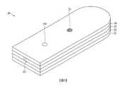
圖2係繪示本申請案檢測條之立體分解示意圖。Fig. 2 is a three-dimensional exploded schematic diagram of the test strip of this application.
圖3係繪示本申請案檢測條之立體示意圖。Fig. 3 is a three-dimensional schematic diagram of the test strip of this application.
圖4係繪示本申請案於製程中複數個相連接之檢測條之示意圖。Fig. 4 is a schematic diagram showing a plurality of connected test strips in the manufacturing process of this application.
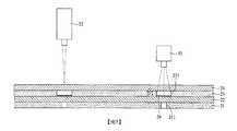
圖5係繪示本申請案於製程中量測實際深度及標示分類標記之示意圖。FIG. 5 is a schematic diagram showing the actual depth measurement and classification marks of this application in the manufacturing process.
圖6係繪示本申請案製造檢測條之流程圖。Figure 6 is a flow chart showing the manufacture of test strips in this application.
以下,就實施本發明之各種實施形態來加以說明。請參照隨附的圖式,並參考其對應的說明。另外,本說明書及圖式中,實質相同或相同的構成會給予相同的符號而省略其重複的說明。Hereinafter, various embodiments for implementing the present invention will be described. Please refer to the attached drawing and refer to its corresponding description. In addition, in this specification and drawings, substantially the same or the same configuration will be given the same reference numeral, and the repeated description will be omitted.
圖2係繪示本申請案檢測條之立體分解示意圖。一檢測條20包含一底層21、一中間層22、一儲血層23及一頂層24。於該頂層24係由一黏著材料所形成之透明膜層,頂層24之上表面標示一分類標記25,藉此區別該檢測條20之特性及其分類。本實施中該分類標記25係用以區別因該儲血層23之狹縫231和該頂層24之交界處至一試劑26上表面的實際深度(如後及圖4再詳述)變異所形成的分類,但並不限於被標示於該頂層24之上表面,亦可標示於該底層21之下表面,以利穿透式光學血糖檢測裝置或穿透式光學血糖計可供辨識後進行血糖數值的補償。在本實施例中,分類標記25可以是利用雷射光機或噴墨印表機產生之印記或標示。本實施例中,分類標記25由雷射光機標示不同灰階度(例如,灰階度1-11)之圖案a、b、c、d、e、f、g、h、i、j、k或點狀印記或標示(如後及表一再詳述)。Fig. 2 is a three-dimensional exploded schematic diagram of the test strip of this application. A
該檢測條20之底層21的材質可以選用不透光之塑膠材料,例如:黑色之聚對苯二甲酸乙二酯(polyethylene terephthalate;PET)之膜層,其包含開孔211及通孔212。該中間層22係一透明膜層具透光特性,其包含和該通孔212對準之一通孔222。該儲血層23的預定厚度較佳為54μm。該儲血層23有一由外部向內延伸之狹縫231,受測者的手指被取樣之血液可由此狹縫231導入內部一儲血區232。該頂層24可以選用具透光特性的透明之塑膠材料,例如:透明之聚對苯二甲酸乙二酯之膜層,其包含通孔242。特別說明的是,該中間層22上係附著一試劑26,試劑26靠近該儲血層23之表面。試劑26係暴露於該狹縫231內,又和該底層21之開孔211中心線彼此對準,致使光線可穿過透明之該頂層24及中間層22並經過試劑26而自該開孔211而出。在本實施例中,底層21、中間層22及頂層24可為相同厚度膜層,而儲血層23的厚度小於其他各層。此外,該底層21係為單面黏著材料所形成之塑膠膜層,而該儲血層23係由一黏著材料所形成之雙面膠膜層。然而,正是因為儲血層23的黏著材料或中間層22上的試劑26塗佈不均或收縮,而較難控制狹縫231中的光徑長(即後述的預定深度)的均勻一致,因此需要藉由該分類標記25區別因該狹縫231和該頂層24之交界處至一試劑26上表面之實際深度變異(即實際深度與預定深度的差異)所形成的不同分類補償。The
此外,另一組之通孔212、222及242之中心線亦彼此對準,其中心線並通過該儲血區232,亦即彼此連通,同樣地藉由光學測量方式以獲得紅血球在血中所佔體積的百分比(亦即血溶比,HCT),更能正確了解血糖測量值,因為血糖測量值常受血溶比影響,所以測得血溶比可以用來校正血糖測量值。血球容積比的測量並非本發明的重點,因此不多做贅述。In addition, the center lines of the through
糖尿病患可使用採血針(圖未示)取手指之血液樣本,而血液會由此該狹縫231導入內部該儲血區232,並和該試劑26反應,反應生成物之濃度和血糖值成正比或一比例關係,並改變血液之顏色,藉由一比色分析可以得知血糖值。在此特別說明的是,比色分析之結果係與血糖數值成正比關係。Diabetes patients can use a blood sampling needle (not shown) to take a blood sample from a finger, and the blood will be introduced into the internal
比色分析(colorimetry)是生化檢測中很常用的方法,其係使用朗伯-比爾定律(Beer-Lambert Law)為計算反應生成物之濃度的根據,其公式表示為:A=αLC (公式一)其中A為光的吸收度;α為光徑長或吸收層厚度;L為光徑長;C為吸光物質的濃度。Colorimetry (colorimetry) is a very commonly used method in biochemical testing. It uses the Beer-Lambert Law as the basis for calculating the concentration of reaction products. Its formula is expressed as: A=αLC (Formula 1 )Where A is the absorbance of light; α is the optical path length or the thickness of the absorption layer; L is the optical path length; C is the concentration of the light-absorbing substance.
圖4係繪示本申請案於製程中的相連接之複數個檢測條之示意圖。於量產檢測條之製程中,將大面積該底層21、中間層22、儲血層23及頂層24依序進行疊置或塗佈,從而形成具有待後續裁切製程的複數個檢測條20之片狀物40。於該片狀物40堆疊完成後,再分別量測各檢測條20中該狹縫231和該頂層24之交界處至一試劑26上表面之實際深度,然後根據預定深度以計算出一補償係數,接著根據該補償係數依序標示各該檢測條20一相應之分類標記25。於本實施例中,該補償係數計算式係為該預定深度與該實際深度的差值乘上該預定深度的倒數。FIG. 4 is a schematic diagram showing a plurality of test strips connected in the manufacturing process of this application. In the production process of mass-produced test strips, a large area of the
沿圖4中A-A剖面線截取具有該狹縫231及試劑26之剖面以繪製圖5,又圖5係繪示本發明實施例於製程中量測實際深度及標示分類標記之示意圖。本實施例係以一光學量測儀器51,例如:膜厚儀,快速地S形來回量測每一個檢測條20中該狹縫231和該頂層23之交界處至該試劑26之上表面之實際深度D’。光學量測儀器51可以發射特定波長之光線,然後根據該試劑26及/或該狹縫231和該頂層23之交界處所反射之光線,以分析而得該實際深度D’。本實施利僅舉例量測該實際深度D’之光學量測儀器為膜厚儀,但本發明並不以此為限。將每一個檢測條20中的實際深度D’代入前述補償係數之計算式,如此可得每一個檢測條20之一相應之補償係數。利用該補償係數和分類標記有對應之關係式或對應表(如後及表一再詳述),再利用雷射光機52或噴墨印表機產生該分類標記25之印記或標示在該頂層24之上表面或該底層21之下表面。A cross-section with the
理論上,該儲血區232之厚度減去該試劑26之厚度即為前述公式一之光徑長。若檢測條20的設計上,該儲血區232預定厚度為54μm,又該試劑26之預定厚度為4μm,為使比色分析之結果為可接受或容許誤差範圍,則需要被控制在光徑長(即狹縫231內的預定深度)等於50μm(理想設計值),否則會得到超出容許誤差之濃度值。但在實際製程上,該儲血層23係與頂層24與中間層22由黏著材料所形成連接,因檢測條製程上的試劑26塗佈不均或上下各層收縮/擠壓,而較難控制其狹縫231中實際深度D’均勻一致,且等於預定深度(D,圖未表示),此即影響前述公式一中光徑長L甚鉅。Theoretically, the thickness of the
然本發明實施例係僅例示光徑長L被控制為固定的一預定深度,亦即50μm。在本實施例中,該預定深度較佳可介於40μm到50μm。藉由前述分類標記25可區別因該儲血層23之狹縫231中實際深度變異所形成的不同分類,如此就能補償公式一因光徑長變異所產生之誤差,進而可直接補償測量後所得的血糖數值。例如:量測所得之實際深度D’為54μm,則公式一所得之數值需補償約(50-54)×2%,亦即負8%,亦即測量後所得的血糖數值的0.92倍就是最後顯示的血糖數值。反之,若該實際厚度D為47μm,則公式一所得之數值需補償約(50-47)×2%,亦即因實際深度(實際光徑長)小於預定深度,所以要將測量後所得的血糖數值補償正6%,亦即測量後所得的血糖數值的1.06倍就是最後顯示的血糖數值。However, the embodiment of the present invention only illustrates that the optical path length L is controlled to a fixed predetermined depth, that is, 50 μm. In this embodiment, the predetermined depth may preferably be between 40 μm and 50 μm. The
圖6係繪示本申請案製造檢測條之流程圖。於步驟61中,提供一片狀物,該片狀物由相連接之複數個檢測條組成,即圖4所示之該片狀物40。然後,提供該檢測條中該狹縫和該頂層之交界處至該試劑之上表面之一預定深度,如步驟62所示。再執行步驟63,量測各該檢測條中該狹縫和該頂層之交界處至該試劑之上表面之一實際深度。接著,根據各該檢測條之該實際深度及該預定深度進行計算以分別得到各該檢測條之一補償係數,如步驟64所示。再執行步驟65,根據各該檢測條之該補償係數,標示各該檢測條相應之一分類標記。最後,分割該片狀物40,以裁切相連接之該複數個檢測條為各個獨立單元,亦即將該片狀物40分割為複數個獨立之檢測條20(如圖3所示),如步驟66所示。在其他實施例中,可省略/置換步驟64及65,在步驟63之後,而藉由各該檢測條之實際深度根據表一所示的補償係數表以對應出的各該檢測條之該補償係數,進而執行標示圖案。例如,測得片狀物40之一檢測條實際深度為54μm,由該補償係數表可得知補償係數為負8%,即可在該檢測條上標示圖案b。Figure 6 is a flow chart showing the manufacture of test strips in this application. In

本發明之技術內容及技術特點已揭示如上,然而熟悉本項技術之人士仍可能基於本發明之教示及揭示而作種種不背離本發明精神之替換及修飾。因此,本發明之保護範圍應不限於實施例所揭示者,而應包括各種不背離本發明之替換及修飾,並為以下之申請專利範圍所涵蓋。The technical content and technical features of the present invention have been disclosed above, but those familiar with the technology may still make various substitutions and modifications based on the teaching and disclosure of the present invention without departing from the spirit of the present invention. Therefore, the protection scope of the present invention should not be limited to those disclosed in the embodiments, but should include various substitutions and modifications that do not deviate from the present invention, and are covered by the following patent applications.
61‧‧‧步驟61‧‧‧Step
62‧‧‧步驟62‧‧‧Step
63‧‧‧步驟63‧‧‧Step
64‧‧‧步驟64‧‧‧Step
65‧‧‧步驟65‧‧‧Step
66‧‧‧步驟66‧‧‧Step
Claims (10)
Translated fromChinesePriority Applications (5)
| Application Number | Priority Date | Filing Date | Title |
|---|---|---|---|
| TW108136543ATWI699535B (en) | 2019-10-09 | 2019-10-09 | Method for manufacturating test strips |
| CN202010997879.7ACN112557663A (en) | 2019-09-25 | 2020-09-21 | Test strip and method for manufacturing test strip |
| EP20198053.9AEP3800265A1 (en) | 2019-09-25 | 2020-09-24 | Test strip and method for manufacturating test strips |
| US17/032,078US11583850B2 (en) | 2019-09-25 | 2020-09-25 | Test strip and method for manufacturating test strips |
| JP2020160932AJP2021051077A (en) | 2019-09-25 | 2020-09-25 | Test strip and method for manufacturing the same |
Applications Claiming Priority (1)
| Application Number | Priority Date | Filing Date | Title |
|---|---|---|---|
| TW108136543ATWI699535B (en) | 2019-10-09 | 2019-10-09 | Method for manufacturating test strips |
Publications (2)
| Publication Number | Publication Date |
|---|---|
| TWI699535Btrue TWI699535B (en) | 2020-07-21 |
| TW202115401A TW202115401A (en) | 2021-04-16 |
Family
ID=72601837
Family Applications (1)
| Application Number | Title | Priority Date | Filing Date |
|---|---|---|---|
| TW108136543ATWI699535B (en) | 2019-09-25 | 2019-10-09 | Method for manufacturating test strips |
Country Status (1)
| Country | Link |
|---|---|
| TW (1) | TWI699535B (en) |
Cited By (2)
| Publication number | Priority date | Publication date | Assignee | Title |
|---|---|---|---|---|
| CN112557663A (en)* | 2019-09-25 | 2021-03-26 | 百略医学科技股份有限公司 | Test strip and method for manufacturing test strip |
| CN114137218A (en)* | 2020-09-04 | 2022-03-04 | 百略医学科技股份有限公司 | Blood glucose detection device capable of correcting measured value according to blood volume ratio |
Citations (3)
| Publication number | Priority date | Publication date | Assignee | Title |
|---|---|---|---|---|
| CN1168988C (en)* | 1996-04-04 | 2004-09-29 | 生命扫描有限公司 | Reagent test strips for glucose determination in blood |
| US6858401B2 (en)* | 1986-08-13 | 2005-02-22 | Lifescan, Inc. | Minimum procedure system for the determination of analytes |
| TW201610426A (en)* | 2014-09-10 | 2016-03-16 | 威爾斯生物公司 | A microfluidic chip and a diagnostic apparatus containing the same |
- 2019
- 2019-10-09TWTW108136543Apatent/TWI699535B/enactive
Patent Citations (3)
| Publication number | Priority date | Publication date | Assignee | Title |
|---|---|---|---|---|
| US6858401B2 (en)* | 1986-08-13 | 2005-02-22 | Lifescan, Inc. | Minimum procedure system for the determination of analytes |
| CN1168988C (en)* | 1996-04-04 | 2004-09-29 | 生命扫描有限公司 | Reagent test strips for glucose determination in blood |
| TW201610426A (en)* | 2014-09-10 | 2016-03-16 | 威爾斯生物公司 | A microfluidic chip and a diagnostic apparatus containing the same |
Cited By (3)
| Publication number | Priority date | Publication date | Assignee | Title |
|---|---|---|---|---|
| CN112557663A (en)* | 2019-09-25 | 2021-03-26 | 百略医学科技股份有限公司 | Test strip and method for manufacturing test strip |
| CN114137218A (en)* | 2020-09-04 | 2022-03-04 | 百略医学科技股份有限公司 | Blood glucose detection device capable of correcting measured value according to blood volume ratio |
| CN114137218B (en)* | 2020-09-04 | 2024-04-12 | 百略医学科技股份有限公司 | Blood sugar detection device capable of correcting measured value according to blood volume ratio |
Also Published As
| Publication number | Publication date |
|---|---|
| TW202115401A (en) | 2021-04-16 |
Similar Documents
| Publication | Publication Date | Title |
|---|---|---|
| DK1111386T4 (en) | A test strip for the determination of an analyte in a liquid stream | |
| TWI699535B (en) | Method for manufacturating test strips | |
| JP5677984B2 (en) | Inspection method and inspection instrument for analyzing body fluid | |
| US20030206302A1 (en) | Apparatuses and methods for analyte concentration determination | |
| US10168278B2 (en) | Total protein measurement using whole blood refractometry | |
| JP2004117339A (en) | Device for determining concentration of assay and its method | |
| CN109891214A (en) | Analysis and test device | |
| US9523643B2 (en) | Protein concentration assay method including pH measurement | |
| KR101176808B1 (en) | Diagnostic tape unit and diagnostic measuring system | |
| CN1162359A (en) | Optically readable strip for analyte detection having on-strip orientation index | |
| US20200249150A1 (en) | Combination optical hemoglobin and electrochemical lead assay | |
| CN105164534A (en) | Method / device for generating a corrected value of an analyte concentration in a sample of a body fluid | |
| CN101874204A (en) | Biosensors and Readouts | |
| TWI701019B (en) | Test strip and optical blood glucose detecting apparatus | |
| US20150014162A1 (en) | Connector for connecting bio-sensor and measuring instrument thereof | |
| US11583850B2 (en) | Test strip and method for manufacturating test strips | |
| JPWO2009037785A1 (en) | Body fluid component analysis device inspection method and body fluid component analysis device | |
| WO2004063393A1 (en) | Measurement of analyte concentration | |
| KR20180111739A (en) | Test strip | |
| JP2008008901A (en) | Solid control and calibration element used in diagnostic analyzer | |
| KR20180000113A (en) | Test strip | |
| HK1155927B (en) | Diagnostic tape unit and diagnostic measuring system |