TWI695702B - Bone screw and percutaneous minimally invasive pedicle fixation system - Google Patents
Bone screw and percutaneous minimally invasive pedicle fixation systemDownload PDFInfo
- Publication number
- TWI695702B TWI695702BTW105115078ATW105115078ATWI695702BTW I695702 BTWI695702 BTW I695702BTW 105115078 ATW105115078 ATW 105115078ATW 105115078 ATW105115078 ATW 105115078ATW I695702 BTWI695702 BTW I695702B
- Authority
- TW
- Taiwan
- Prior art keywords
- calibration
- sleeve
- fixing seat
- screw
- positioning sleeve
- Prior art date
Links
- 210000000988bone and boneAnatomy0.000titleclaimsabstractdescription91
- 238000011038discontinuous diafiltration by volume reductionMethods0.000claimsdescription10
- 230000001154acute effectEffects0.000claimsdescription3
- 206010052428WoundDiseases0.000description10
- 208000027418Wounds and injuryDiseases0.000description10
- 238000009434installationMethods0.000description9
- 238000001356surgical procedureMethods0.000description8
- 239000007943implantSubstances0.000description3
- 238000002324minimally invasive surgeryMethods0.000description3
- 206010072170Skin woundDiseases0.000description2
- 201000006490SpondylolysisDiseases0.000description2
- 238000004891communicationMethods0.000description2
- 230000035876healingEffects0.000description2
- 230000002265preventionEffects0.000description2
- 238000011084recoveryMethods0.000description2
- 208000007103SpondylolisthesisDiseases0.000description1
- 229910001069Ti alloyInorganic materials0.000description1
- 230000004323axial lengthEffects0.000description1
- 230000007850degenerationEffects0.000description1
- 230000006866deteriorationEffects0.000description1
- 201000010099diseaseDiseases0.000description1
- 208000037265diseases, disorders, signs and symptomsDiseases0.000description1
- 238000003780insertionMethods0.000description1
- 230000037431insertionEffects0.000description1
- 238000000034methodMethods0.000description1
- 238000012986modificationMethods0.000description1
- 230000004048modificationEffects0.000description1
- 210000001519tissueAnatomy0.000description1
- 230000009466transformationEffects0.000description1
Images


Classifications
- A—HUMAN NECESSITIES
- A61—MEDICAL OR VETERINARY SCIENCE; HYGIENE
- A61B—DIAGNOSIS; SURGERY; IDENTIFICATION
- A61B17/00—Surgical instruments, devices or methods
- A61B17/56—Surgical instruments or methods for treatment of bones or joints; Devices specially adapted therefor
- A61B17/58—Surgical instruments or methods for treatment of bones or joints; Devices specially adapted therefor for osteosynthesis, e.g. bone plates, screws or setting implements
- A61B17/68—Internal fixation devices, including fasteners and spinal fixators, even if a part thereof projects from the skin
- A61B17/84—Fasteners therefor or fasteners being internal fixation devices
- A61B17/86—Pins or screws or threaded wires; nuts therefor
- A61B17/8625—Shanks, i.e. parts contacting bone tissue
- A—HUMAN NECESSITIES
- A61—MEDICAL OR VETERINARY SCIENCE; HYGIENE
- A61B—DIAGNOSIS; SURGERY; IDENTIFICATION
- A61B17/00—Surgical instruments, devices or methods
- A61B17/56—Surgical instruments or methods for treatment of bones or joints; Devices specially adapted therefor
- A61B17/58—Surgical instruments or methods for treatment of bones or joints; Devices specially adapted therefor for osteosynthesis, e.g. bone plates, screws or setting implements
- A61B17/68—Internal fixation devices, including fasteners and spinal fixators, even if a part thereof projects from the skin
- A61B17/685—Elements to be fitted on the end of screws or wires, e.g. protective caps
- A—HUMAN NECESSITIES
- A61—MEDICAL OR VETERINARY SCIENCE; HYGIENE
- A61B—DIAGNOSIS; SURGERY; IDENTIFICATION
- A61B17/00—Surgical instruments, devices or methods
- A61B17/56—Surgical instruments or methods for treatment of bones or joints; Devices specially adapted therefor
- A61B17/58—Surgical instruments or methods for treatment of bones or joints; Devices specially adapted therefor for osteosynthesis, e.g. bone plates, screws or setting implements
- A61B17/68—Internal fixation devices, including fasteners and spinal fixators, even if a part thereof projects from the skin
- A61B17/70—Spinal positioners or stabilisers, e.g. stabilisers comprising fluid filler in an implant
- A61B17/7001—Screws or hooks combined with longitudinal elements which do not contact vertebrae
- A61B17/7035—Screws or hooks, wherein a rod-clamping part and a bone-anchoring part can pivot relative to each other
- A61B17/7037—Screws or hooks, wherein a rod-clamping part and a bone-anchoring part can pivot relative to each other wherein pivoting is blocked when the rod is clamped
- A—HUMAN NECESSITIES
- A61—MEDICAL OR VETERINARY SCIENCE; HYGIENE
- A61B—DIAGNOSIS; SURGERY; IDENTIFICATION
- A61B17/00—Surgical instruments, devices or methods
- A61B17/00234—Surgical instruments, devices or methods for minimally invasive surgery
- A—HUMAN NECESSITIES
- A61—MEDICAL OR VETERINARY SCIENCE; HYGIENE
- A61B—DIAGNOSIS; SURGERY; IDENTIFICATION
- A61B17/00—Surgical instruments, devices or methods
- A61B17/56—Surgical instruments or methods for treatment of bones or joints; Devices specially adapted therefor
- A61B17/58—Surgical instruments or methods for treatment of bones or joints; Devices specially adapted therefor for osteosynthesis, e.g. bone plates, screws or setting implements
- A61B17/68—Internal fixation devices, including fasteners and spinal fixators, even if a part thereof projects from the skin
- A61B17/70—Spinal positioners or stabilisers, e.g. stabilisers comprising fluid filler in an implant
- A61B17/7047—Clamps comprising opposed elements which grasp one vertebra between them
- A—HUMAN NECESSITIES
- A61—MEDICAL OR VETERINARY SCIENCE; HYGIENE
- A61B—DIAGNOSIS; SURGERY; IDENTIFICATION
- A61B17/00—Surgical instruments, devices or methods
- A61B17/56—Surgical instruments or methods for treatment of bones or joints; Devices specially adapted therefor
- A61B17/58—Surgical instruments or methods for treatment of bones or joints; Devices specially adapted therefor for osteosynthesis, e.g. bone plates, screws or setting implements
- A61B17/68—Internal fixation devices, including fasteners and spinal fixators, even if a part thereof projects from the skin
- A61B17/70—Spinal positioners or stabilisers, e.g. stabilisers comprising fluid filler in an implant
- A61B17/7056—Hooks with specially-designed bone-contacting part
- A—HUMAN NECESSITIES
- A61—MEDICAL OR VETERINARY SCIENCE; HYGIENE
- A61B—DIAGNOSIS; SURGERY; IDENTIFICATION
- A61B17/00—Surgical instruments, devices or methods
- A61B17/56—Surgical instruments or methods for treatment of bones or joints; Devices specially adapted therefor
- A61B17/58—Surgical instruments or methods for treatment of bones or joints; Devices specially adapted therefor for osteosynthesis, e.g. bone plates, screws or setting implements
- A61B17/68—Internal fixation devices, including fasteners and spinal fixators, even if a part thereof projects from the skin
- A61B17/70—Spinal positioners or stabilisers, e.g. stabilisers comprising fluid filler in an implant
- A61B17/7062—Devices acting on, attached to, or simulating the effect of, vertebral processes, vertebral facets or ribs ; Tools for such devices
- A61B17/7067—Devices bearing against one or more spinous processes and also attached to another part of the spine; Tools therefor
- A—HUMAN NECESSITIES
- A61—MEDICAL OR VETERINARY SCIENCE; HYGIENE
- A61B—DIAGNOSIS; SURGERY; IDENTIFICATION
- A61B17/00—Surgical instruments, devices or methods
- A61B17/56—Surgical instruments or methods for treatment of bones or joints; Devices specially adapted therefor
- A61B17/58—Surgical instruments or methods for treatment of bones or joints; Devices specially adapted therefor for osteosynthesis, e.g. bone plates, screws or setting implements
- A61B17/68—Internal fixation devices, including fasteners and spinal fixators, even if a part thereof projects from the skin
- A61B17/70—Spinal positioners or stabilisers, e.g. stabilisers comprising fluid filler in an implant
- A61B17/7074—Tools specially adapted for spinal fixation operations other than for bone removal or filler handling
- A61B17/7076—Tools specially adapted for spinal fixation operations other than for bone removal or filler handling for driving, positioning or assembling spinal clamps or bone anchors specially adapted for spinal fixation
- A—HUMAN NECESSITIES
- A61—MEDICAL OR VETERINARY SCIENCE; HYGIENE
- A61B—DIAGNOSIS; SURGERY; IDENTIFICATION
- A61B17/00—Surgical instruments, devices or methods
- A61B17/56—Surgical instruments or methods for treatment of bones or joints; Devices specially adapted therefor
- A61B17/58—Surgical instruments or methods for treatment of bones or joints; Devices specially adapted therefor for osteosynthesis, e.g. bone plates, screws or setting implements
- A61B17/68—Internal fixation devices, including fasteners and spinal fixators, even if a part thereof projects from the skin
- A61B17/70—Spinal positioners or stabilisers, e.g. stabilisers comprising fluid filler in an implant
- A61B17/7074—Tools specially adapted for spinal fixation operations other than for bone removal or filler handling
- A61B17/7083—Tools for guidance or insertion of tethers, rod-to-anchor connectors, rod-to-rod connectors, or longitudinal elements
- A61B17/7085—Tools for guidance or insertion of tethers, rod-to-anchor connectors, rod-to-rod connectors, or longitudinal elements for insertion of a longitudinal element down one or more hollow screw or hook extensions, i.e. at least a part of the element within an extension has a component of movement parallel to the extension's axis
- A—HUMAN NECESSITIES
- A61—MEDICAL OR VETERINARY SCIENCE; HYGIENE
- A61B—DIAGNOSIS; SURGERY; IDENTIFICATION
- A61B17/00—Surgical instruments, devices or methods
- A61B17/56—Surgical instruments or methods for treatment of bones or joints; Devices specially adapted therefor
- A61B17/58—Surgical instruments or methods for treatment of bones or joints; Devices specially adapted therefor for osteosynthesis, e.g. bone plates, screws or setting implements
- A61B17/68—Internal fixation devices, including fasteners and spinal fixators, even if a part thereof projects from the skin
- A61B17/84—Fasteners therefor or fasteners being internal fixation devices
- A61B17/86—Pins or screws or threaded wires; nuts therefor
- A61B17/8605—Heads, i.e. proximal ends projecting from bone
- A61B17/861—Heads, i.e. proximal ends projecting from bone specially shaped for gripping driver
- A61B17/8615—Heads, i.e. proximal ends projecting from bone specially shaped for gripping driver at the central region of the screw head
- A—HUMAN NECESSITIES
- A61—MEDICAL OR VETERINARY SCIENCE; HYGIENE
- A61B—DIAGNOSIS; SURGERY; IDENTIFICATION
- A61B17/00—Surgical instruments, devices or methods
- A61B17/56—Surgical instruments or methods for treatment of bones or joints; Devices specially adapted therefor
- A61B17/58—Surgical instruments or methods for treatment of bones or joints; Devices specially adapted therefor for osteosynthesis, e.g. bone plates, screws or setting implements
- A61B17/68—Internal fixation devices, including fasteners and spinal fixators, even if a part thereof projects from the skin
- A61B17/84—Fasteners therefor or fasteners being internal fixation devices
- A61B17/86—Pins or screws or threaded wires; nuts therefor
- A61B17/8605—Heads, i.e. proximal ends projecting from bone
- A61B17/861—Heads, i.e. proximal ends projecting from bone specially shaped for gripping driver
- A61B17/862—Heads, i.e. proximal ends projecting from bone specially shaped for gripping driver at the periphery of the screw head
- A—HUMAN NECESSITIES
- A61—MEDICAL OR VETERINARY SCIENCE; HYGIENE
- A61B—DIAGNOSIS; SURGERY; IDENTIFICATION
- A61B17/00—Surgical instruments, devices or methods
- A61B17/56—Surgical instruments or methods for treatment of bones or joints; Devices specially adapted therefor
- A61B17/58—Surgical instruments or methods for treatment of bones or joints; Devices specially adapted therefor for osteosynthesis, e.g. bone plates, screws or setting implements
- A61B17/68—Internal fixation devices, including fasteners and spinal fixators, even if a part thereof projects from the skin
- A61B17/84—Fasteners therefor or fasteners being internal fixation devices
- A61B17/86—Pins or screws or threaded wires; nuts therefor
- A61B17/8625—Shanks, i.e. parts contacting bone tissue
- A61B17/8635—Tips of screws
- A—HUMAN NECESSITIES
- A61—MEDICAL OR VETERINARY SCIENCE; HYGIENE
- A61B—DIAGNOSIS; SURGERY; IDENTIFICATION
- A61B17/00—Surgical instruments, devices or methods
- A61B17/00234—Surgical instruments, devices or methods for minimally invasive surgery
- A61B2017/00238—Type of minimally invasive operation
- A—HUMAN NECESSITIES
- A61—MEDICAL OR VETERINARY SCIENCE; HYGIENE
- A61B—DIAGNOSIS; SURGERY; IDENTIFICATION
- A61B17/00—Surgical instruments, devices or methods
- A61B17/56—Surgical instruments or methods for treatment of bones or joints; Devices specially adapted therefor
- A61B2017/564—Methods for bone or joint treatment
- A—HUMAN NECESSITIES
- A61—MEDICAL OR VETERINARY SCIENCE; HYGIENE
- A61B—DIAGNOSIS; SURGERY; IDENTIFICATION
- A61B17/00—Surgical instruments, devices or methods
- A61B17/56—Surgical instruments or methods for treatment of bones or joints; Devices specially adapted therefor
- A61B17/58—Surgical instruments or methods for treatment of bones or joints; Devices specially adapted therefor for osteosynthesis, e.g. bone plates, screws or setting implements
- A61B17/68—Internal fixation devices, including fasteners and spinal fixators, even if a part thereof projects from the skin
- A61B2017/681—Alignment, compression, or distraction mechanisms
- A—HUMAN NECESSITIES
- A61—MEDICAL OR VETERINARY SCIENCE; HYGIENE
- A61B—DIAGNOSIS; SURGERY; IDENTIFICATION
- A61B90/00—Instruments, implements or accessories specially adapted for surgery or diagnosis and not covered by any of the groups A61B1/00 - A61B50/00, e.g. for luxation treatment or for protecting wound edges
- A61B90/03—Automatic limiting or abutting means, e.g. for safety
- A61B2090/037—Automatic limiting or abutting means, e.g. for safety with a frangible part, e.g. by reduced diameter
Landscapes
- Health & Medical Sciences (AREA)
- Orthopedic Medicine & Surgery (AREA)
- Life Sciences & Earth Sciences (AREA)
- Surgery (AREA)
- Neurology (AREA)
- Heart & Thoracic Surgery (AREA)
- Engineering & Computer Science (AREA)
- Biomedical Technology (AREA)
- Nuclear Medicine, Radiotherapy & Molecular Imaging (AREA)
- Medical Informatics (AREA)
- Molecular Biology (AREA)
- Animal Behavior & Ethology (AREA)
- General Health & Medical Sciences (AREA)
- Public Health (AREA)
- Veterinary Medicine (AREA)
- Surgical Instruments (AREA)
- Prostheses (AREA)
Abstract
Description
Translated fromChinese本發明係關於骨釘及經皮微創椎弓根固定系統,特別是關於適於用在經皮微創脊椎骨治療的骨釘固定系統。The invention relates to a bone nail and a percutaneous minimally invasive pedicle fixation system, in particular to a bone nail fixation system suitable for percutaneous minimally invasive vertebral bone treatment.
固定系統的微創侵入性手術被用於治療脊椎骨(vertebrae)中,由於傷口小,該等手術可大幅減少對於治療部分及其附近組織的傷害、提升手術的安全性及減少治癒與恢復時間。為了固定系統的準確定位及校準,固定系統的骨釘典型地經提供有定位套,因此,固定系統的骨釘可在進行手術時自人體外被定位且校準。Minimally invasive surgery with a fixed system is used to treat the vertebrae. Due to the small wounds, these surgeries can greatly reduce the damage to the treatment part and nearby tissues, improve the safety of the surgery, and reduce the healing and recovery time. For accurate positioning and calibration of the fixation system, the bone nails of the fixation system are typically provided with positioning sleeves, therefore, the bone nails of the fixation system can be positioned and calibrated from outside the body when performing surgery.
習知的骨釘固定系統需要一分離的校準元件,以在將骨釘插入骨頭中時校準骨釘,該分離的校準元件相對複雜及/或具有複數個組件,而導致不便利性且甚至在手術中需要具有較大寬度或長度的傷口。因此,有需要發展一種相對簡單且便利的骨釘固定系統,再者,多於一個的骨釘被插入患者的脊椎骨中,被期待提供一種減小手術步驟的數量及/或手術時間的骨釘固定系統。The conventional bone nail fixation system requires a separate calibration element to calibrate the bone nail when the bone nail is inserted into the bone. The separate calibration element is relatively complex and/or has multiple components, resulting in inconvenience and even A wound with a larger width or length is required during surgery. Therefore, there is a need to develop a relatively simple and convenient bone nail fixation system. Furthermore, more than one bone nail is inserted into the patient's spine, and it is expected to provide a bone nail that reduces the number of surgical steps and/or the operation time Fixed system.
本發明可改善在侵入型脊椎骨手術中安裝固定元件的效率及準確性。在經皮侵入型脊椎固手術中,較佳的是減小手術造成的傷口面積或尺寸,本發明的固定系統包含長管狀結構,其在插入骨釘時有助於校準骨釘,該長管狀結構可為具有用以使骨釘通過的通道的圓柱形校準套,且與將藉由骨釘被插入且固定至骨頭的基座一體地形成,在該植入程序完成之後該結構可接著被移除。當多於一個的骨釘需要彼此相鄰地被植入時,較佳的是該固定系統的該被封閉的長管狀結構的直徑是較小的,或者具有經開發的較適當形狀,以使該等校準套可被緊密地堆疊在一起且因此在插入複數個骨釘時僅需要小的患者傷口面積。The present invention can improve the efficiency and accuracy of installing fixation elements in invasive spinal surgery. In percutaneous invasive spinal fixation surgery, it is preferable to reduce the area or size of the wound caused by the surgery. The fixation system of the present invention includes a long tubular structure, which helps when inserting bone nailsFor calibrating bone nails, the long tubular structure may be a cylindrical calibration sleeve with a passage for the bone nails to pass through, and is formed integrally with the base to be inserted and fixed to the bone by the bone nails, where the implant The structure can then be removed after the procedure is completed. When more than one bone nail needs to be implanted next to each other, it is preferred that the diameter of the closed long tubular structure of the fixation system is smaller, or has a more appropriate shape developed so that These calibration sleeves can be closely stacked together and therefore only require a small patient wound area when inserting multiple bone screws.
較佳的骨釘固定系統具有定位套,該定位套包含一固定座、一校準套及穿過該定位套形成的一骨釘本體通道,該固定座及該校準套是一體地構形,一通孔在固定座的底部且沿著骨釘本體通道被形成,該通孔具有小於骨釘本體的球形頭部直徑的一直徑;該固定座的壁具有彼此相對且朝向固定座頂部開放的兩個開口,使得穿過固定座的一第一通道被形成在該等開口之間且側向穿過固定座;該校準套具有一壁部分及一體積減小部分;一長形開口被形成在該壁部分上且與該等開口中一者連通;該體積減小部分是具有壁的一部分被移除且因此自固定座的外表面內縮的部分,且與該等開口中另一者連通的一導引開口被形成在體積減小部分中;及一易斷裂部分被形成在校準套及固定座之間,以促進校準套自定位套的移除。該易斷裂部分是選自下列中一者:(a)一環形槽;(b)相對於固定座的寬度或直徑具有明顯地減小校準套寬度或直徑的一部分;或(c)沿著校準套及固定座間的邊界形成的一系列的小孔。定位套可進一步包含複數個校準開口在校準套的壁部分位於遠離固定座的遠側末端,及一第二凹槽在該等校準開口的稍微下方處且環繞校準套的中間部分,使得具有該等校準開口的部分可被斷裂。The preferred bone screw fixing system has a positioning sleeve, which includes a fixing seat, a calibration sleeve, and a bone nail body channel formed through the positioning sleeve. The fixing seat and the calibration sleeve are integrally configured, and a A hole is formed at the bottom of the fixing base and along the screw body channel, the through hole has a diameter smaller than the diameter of the spherical head of the bone body; the wall of the fixing base has two opposite to each other and open toward the top of the fixing base An opening such that a first passage through the fixing seat is formed between the openings and laterally through the fixing seat; the calibration sleeve has a wall portion and a volume-reducing portion; an elongated opening is formed in the The wall portion is in communication with one of the openings; the volume-reducing portion is a portion with the wall removed and thus retracted from the outer surface of the mount, and is in communication with the other of the openings A guide opening is formed in the volume reduction portion; and a frangible portion is formed between the calibration sleeve and the fixing seat to facilitate the removal of the calibration sleeve from the positioning sleeve. The frangible portion is selected from one of the following: (a) an annular groove; (b) a portion that significantly reduces the width or diameter of the calibration sleeve relative to the width or diameter of the mount; or (c) along the calibration A series of small holes formed by the boundary between the sleeve and the fixed seat. The positioning sleeve may further include a plurality of calibration openings at the wall portion of the calibration sleeve located at the distal end away from the fixing seat, and a second groove slightly below the calibration openings and surrounding the middle portion of the calibration sleeve, such that The part of the calibration opening can be broken.
較佳的是,該體積減小部分的整個壁被移除,使得體積減小部分自固定座的外表面內縮,由於該壁的移除形成導引開口,且該校準套的截面的內縮面積,自鄰近固定座的一端朝向遠離固定座的遠側端逐漸增加。更進一步的是,在校準套的長形孔的遠側末端,該截面的內縮面積較佳等於或大於固定座頂部的截面的面積的一半。此外,固定座具有位在固定座底部部分的一球形坑,在球形坑上方的內表面經構形具有一螺紋用於骨釘的固定,且定位套具有85毫米至165毫米的一縱向長度。Preferably, the entire wall of the volume-reducing portion is removed, so that the volume-reducing portion is retracted from the outer surface of the fixing seat, since the removal of the wall forms a guide opening, and the calibrationThe shrinkage area of the cross section of the sleeve gradually increases from the end adjacent to the fixing seat toward the distal end away from the fixing seat. Furthermore, at the distal end of the elongated hole of the calibration sleeve, the reduced area of the cross section is preferably equal to or greater than half the area of the cross section of the top of the fixing seat. In addition, the fixing base has a spherical pit located at the bottom portion of the fixing base, the inner surface above the spherical pit is configured with a thread for fixing the bone nail, and the positioning sleeve has a longitudinal length of 85 mm to 165 mm.
另一方面,本案說明一種骨釘,其包含如前述說明的一定位套及一骨釘本體。骨釘本體包含包含一螺桿及連接至螺桿頂部的一球形頭部,骨釘本體被可旋轉地連接至該定位套的一底部部分,使得骨釘本體的定位部分被設置在固定座的球形坑中。該球形頭部的外徑大於螺桿的外徑,且球形頭部經構形具有一接合槽及一止滑紋,該接合槽符合一驅動工具的形狀且該止滑紋增加該球形頭部外表面的摩擦力。螺桿具有包含一外螺紋的桿部分及包含一銳角角度的尖端。當骨釘被植入至一脊椎骨中時,該校準套的校準開口保留在該皮膚上方。On the other hand, this case describes a bone nail including a positioning sleeve and a bone nail body as described above. The bone screw body includes a screw and a spherical head connected to the top of the screw, the bone screw body is rotatably connected to a bottom portion of the positioning sleeve, so that the positioning portion of the bone screw body is provided in a spherical pit of a fixed seat in. The outer diameter of the spherical head is larger than the outer diameter of the screw, and the spherical head is configured to have an engaging groove and an anti-slip line, the engaging groove conforms to the shape of a driving tool and the anti-slip line increases outside the spherical head Friction on the surface. The screw has a shaft portion that includes an external thread and a tip that includes an acute angle. When the bone screw is implanted into a vertebra, the calibration opening of the calibration sleeve remains above the skin.
在又另一方面,本案說明一種經皮微創椎弓根固定系統,其包含如上所述的一骨釘、一鉤桿及一固定螺釘。鉤桿包含具有多邊形結構的一桿,該多邊形結構位於桿的後側端,使得鉤桿的安裝角度及位置可藉由多邊形結構被調整。固定螺釘可與該球形坑上方的內表面的螺紋鎖固,以將鉤桿與固定座固定。當骨釘的螺桿被植入至一脊椎骨中時,鉤桿可通過皮膚的傷口被插入,沿著校準套被導引至定位套的底部,且可延伸穿過校準套的長形開口及導引開口。In yet another aspect, this case describes a percutaneous minimally invasive pedicle fixation system that includes a bone nail, a hook rod, and a fixation screw as described above. The hook lever includes a lever with a polygonal structure, which is located at the rear end of the lever, so that the installation angle and position of the hook lever can be adjusted by the polygonal structure. The fixing screw can be locked with the thread on the inner surface above the spherical pit to fix the hook rod and the fixing seat. When the screw of the bone screw is implanted into a vertebra, the hook rod can be inserted through the skin wound, guided along the calibration sleeve to the bottom of the positioning sleeve, and can extend through the elongated opening and guide of the calibration sleeve Lead the opening.
藉此,由於定位套被提供有長形孔及導引開口,使得連接構件可穿過定位套並沿著校準套被導引至定位套的底部,本案的經皮微創椎弓根固定系統使得連接構件的安裝更為容易。此外,因為定位套,手術中的傷口的面積可以藉由堆疊複數個骨釘的定位套而被減小。連接構件可為連接桿、鉤桿或其類似物,用以連接上部及下部脊椎骨或連接椎弓根與脊椎骨而形成脊椎固定系統,以解決脊椎退化或相關疾病造成的不穩定性。一種具有大約5.5毫米直徑的鈦合金連接桿可被用於作為一種連接桿。In this way, since the positioning sleeve is provided with an elongated hole and a guide opening, the connecting member can pass through the positioning sleeve and be guided along the calibration sleeve to the bottom of the positioning sleeve, the percutaneous minimally invasive pedicle fixation system in this case Makes the installation of the connection member easier. In addition, because of the positioning sleeve, the area of the wound in the operation can be reduced by stacking the positioning sleeves of a plurality of bone nails. The connecting member may be a connecting rod, a hook rod or the like to connect the upper and lower vertebrae orConnect the pedicle with the vertebrae to form a spinal fixation system to solve the instability caused by spinal degeneration or related diseases. A titanium alloy connecting rod having a diameter of about 5.5 mm can be used as a connecting rod.
上述說明並不意欲用以說明所揭露的每一實施方式或本發明的所有實施態樣,以下圖式及詳細說明特別提供例示性實施方式作為例子。The above description is not intended to describe each disclosed embodiment or all implementations of the present invention. The following drawings and detailed description particularly provide exemplary embodiments as examples.
100‧‧‧骨釘本體100‧‧‧Bone nail body
110‧‧‧球形頭部110‧‧‧Spherical head
112‧‧‧接合槽112‧‧‧slot
113‧‧‧止滑紋113‧‧‧ Anti-slip pattern
120‧‧‧螺桿120‧‧‧screw
121‧‧‧外螺紋121‧‧‧Male thread
122‧‧‧尖端122‧‧‧tip
200‧‧‧定位套200‧‧‧Positioning sleeve
210‧‧‧固定座210‧‧‧Fixed seat
211‧‧‧球形坑211‧‧‧Spherical pit
213‧‧‧螺紋213‧‧‧Thread
214‧‧‧開口214‧‧‧ opening
220‧‧‧校準套220‧‧‧Calibration kit
221‧‧‧校準開口221‧‧‧Calibration opening
222‧‧‧校準開口222‧‧‧Calibration opening
223‧‧‧長形孔223‧‧‧Long hole
224‧‧‧第二凹槽224‧‧‧Second groove
225‧‧‧導引開口225‧‧‧Guide opening
228‧‧‧壁部分228‧‧‧ Wall part
229‧‧‧體積減小部分229‧‧‧Volume reduction
230‧‧‧環形槽230‧‧‧Annular groove
250‧‧‧骨釘本體通道250‧‧‧Bone nail body channel
260‧‧‧第一通道260‧‧‧ First channel
501‧‧‧皮膚501‧‧‧Skin
501A‧‧‧傷口501A‧‧‧Wound
502‧‧‧脊椎骨502‧‧‧spine
503‧‧‧椎弓峽部503‧‧‧ Arch
600‧‧‧校準治具600‧‧‧ Calibration fixture
701‧‧‧連接桿701‧‧‧ connecting rod
800‧‧‧鉤桿800‧‧‧Hook lever
801‧‧‧桿801‧‧‧rod
802‧‧‧彎鈎部802‧‧‧Hook
803‧‧‧多角形結構803‧‧‧Polygonal structure
900‧‧‧固定螺釘900‧‧‧fixing screw
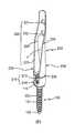
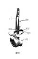
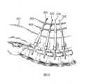
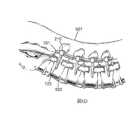
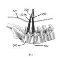
圖1描繪根據本發明一種實施方式的骨釘的立體圖;圖2描繪根據本發明一種實施方式的骨釘在分解狀態下的立體圖;圖3描繪根據本發明一種實施方式的骨釘在組合狀態下的側視圖;圖4描繪根據本發明一種實施方式的鉤桿的立體圖;圖5A至5E描繪根據本發明一種實施方式的椎弓根固定系統的安裝,其中圖5A展示骨釘被植入且鎖入脊椎骨,圖5B展示鉤桿沿著校準套被導引至定位套的底部,圖5C展示鉤桿向外延伸穿過校準套的長形開口及導引開口且被鈎於椎弓峽部,圖5D展示鉤桿被鈎於椎弓峽部且固定至骨釘的固定座,及圖5E展示鉤桿被固定至骨釘的固定座的另一視圖;圖6A至6E描繪根據本發明另一實施方式的骨釘的安裝,其中圖6A展示複數個骨釘被植入脊椎骨中,圖6B展示圖6A的複數個骨釘藉由校準治具校準,圖6C展示圖6B的複數個骨釘藉由校準治具暫時固定且一連接桿定位在固定座中,圖6D展示連接桿已被固定至複數個骨釘的固定座且該等定位套的校準套已被移除,及圖6E展示連接桿被固定至複數個骨釘的固定座。1 depicts a perspective view of a bone nail according to an embodiment of the present invention; FIG. 2 depicts a perspective view of a bone nail according to an embodiment of the present invention in an exploded state; FIG. 3 depicts a bone nail according to an embodiment of the present invention in a combined state Figure 4A depicts a perspective view of a hook rod according to an embodiment of the present invention; Figures 5A to 5E depict the installation of a pedicle fixation system according to an embodiment of the present invention, wherein Figure 5A shows the bone screw implanted and locked Into the vertebrae, Fig. 5B shows that the hook rod is guided along the calibration sleeve to the bottom of the positioning sleeve, and Fig. 5C shows that the hook rod extends outward through the elongated opening and the guide opening of the calibration sleeve and is hooked to the vertebral arch isthmus, FIG. 5D shows the hook bar being hooked to the pedicle isthmus and fixed to the anchor of the bone screw, and FIG. 5E shows another view of the hook bar being fixed to the anchor of the bone screw; FIGS. 6A to 6E depict another The installation of the bone screw of the embodiment, wherein FIG. 6A shows that a plurality of bone screws are implanted in the vertebrae, FIG. 6B shows that the plurality of bone screws of FIG. 6A are calibrated by a calibration jig, and FIG. 6C shows that the plurality of bone screws of FIG. 6B are borrowed It is temporarily fixed by the calibration jig and a connecting rod is positioned in the fixing seat. FIG. 6D shows that the connecting rod has been fixed to the fixing seat of a plurality of bone screws and the calibration sleeves of these positioning sleeves have been removed, and FIG. 6E shows the connection. The rod is fixed to the fixing seat of a plurality of bone nails.
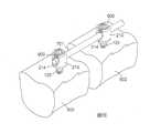
圖7A及7B描繪根據本發明另一實施方式的骨釘的安裝,其中圖7A展示複數個骨釘通過皮膚上的同一個小傷口被植入脊椎骨,及圖7B展示兩個骨釘的定位套的上部保留在皮膚上方且被堆疊在一起。7A and 7B depict the installation of bone nails according to another embodiment of the present invention, wherein7A shows that a plurality of bone nails are implanted into the vertebrae through the same small wound on the skin, and FIG. 7B shows that the upper parts of the positioning sleeves of the two bone nails remain above the skin and are stacked together.
以下說明中,參考所附圖式。應瞭解在不脫離本案揭露的範圍或精神下其他實施方式可被思及且可被完成,以下詳細說明係用以較佳地描述本發明,而非限制本發明為以下的說明。In the following description, reference is made to the attached drawings. It should be understood that other embodiments can be considered and can be completed without departing from the scope or spirit of the disclosure. The following detailed description is used to better describe the present invention, rather than limiting the present invention to the following description.
如圖1至3所示,骨釘包含定位套200及骨釘本體100,骨釘本體100包含螺桿120及球形頭部110;骨釘本體100可以通過校準套220且可選轉地連接至定位套200的一底部部分。球形頭部110具有大於螺桿120外徑的一外徑,定位套200包含固定座210及校準套220及穿過定位套形成的骨釘本體通道250,固定座210及校準套220兩者係一體地形成。固定座210的底部形成有沿著骨釘本體通道250的一通孔,其具有小於骨釘本體100的球形頭部110的一直徑。固定座210的壁具有彼此相對且朝向固定座210頂部開放的兩開口214,使得穿過固定座210的第一通道260形成在開口214之間且側向地穿過固定座210。固定座210進一步包含位在固定座210的底部部分的球形坑211及位於球形坑211上方經構形具有螺紋213的內表面。As shown in FIGS. 1 to 3, the bone nail includes a
校準套220具有壁部分228及體積減小部分229,壁部分228經形成具有一壁、與該等開口214中一者連通的一長形孔223及位於遠離固定座210的遠側末端的複數個校準開口221,222。校準套220進一步具有第二凹槽224,第二凹槽224在校準開口221,222的稍微下方處且環繞校準套220,使得具有校準開口221,222的部分可被輕易斷裂。體積減小部分229是具有壁的一部分被移除且因此自固定座210的外表面內縮的部分,導引開口225形成在該體積減小部分229中且與該等開口214中另一者連通。另一較佳實施方式係體積減小部分229的整個壁被移除,且因此體積減小部分229形成導引開口225。在一較佳實施方式中,該校準套的截面的內縮面積,自鄰近固定座210的一端朝向遠離固定座210的末端逐漸增加,且在長形孔223的遠側末端大於固定座210頂部的截面的面積的一半,定位套200較佳具有自85毫米至165毫米的軸向長度。The
此外,定位套200具有易斷裂部分,以促進校準套220的移除。舉例而言,環形槽230形成在校準套220及固定座210之間,以使校準套220可以藉由使環形槽230斷裂自定位套200被輕易地移除。另一種例子是,易斷裂部分為相對於固定座210的寬度或直徑具有明顯地減小校準套寬度或直徑的部分。易斷裂部分也可以是沿著校準套220及固定座210間的邊界形成的一系列的小孔。In addition, the
在圖2中,骨釘是在分解狀態中。骨釘本體100包含螺桿120及連接至螺桿120頂部部分的球形頭部110,球形頭部110具有接合槽112及止滑紋113,接合槽112符合驅動工具的形狀,止滑紋113用以增加球形頭部110外表面的摩擦力。螺桿120具有包含外螺紋121的桿體部分及尖端122,尖端122經形成有位在桿體部分末端的銳角。In Fig. 2, the bone nail is in an exploded state. The
在骨釘的組合狀態下,如圖1及3所示,骨釘本體100是可旋轉地連接至定位套200的底部部分,使得骨釘本體100的球形頭部110被設置在固定座210的球形坑211中(如圖2所示)。In the assembled state of the bone nail, as shown in FIGS. 1 and 3, the
圖5A至5E展示經皮微創椎弓根固定系統。經皮微創椎弓根固定系統包含如上所述的骨釘、鉤桿800及固定螺釘900。在此所述的弓根可能具有缺口或椎弓解離症(spondylolysis)的情況。如圖4所展示的鉤桿800具有彎鈎部802、桿801及位在桿801的後側端的多角形結構803,多角形結構803藉由工具促進鉤桿800的安裝角度及位置的調整。如圖5D所示的固定螺釘900,可被沿著在球形坑211上方的定位套200的內表面的螺紋213鎖固,以將鉤桿800與固定座210固定。Figures 5A to 5E show a percutaneous minimally invasive pedicle fixation system. The percutaneous minimally invasive pedicle fixation system includes the bone nail,
以下參閱圖5A至5E說明經皮微創椎弓根固定系統手術的一種例子。首先,驅動工具(圖中未展示)的前端抵靠骨釘本體100的球形頭部110的接合槽112,並進入定位套200以旋轉骨釘本體100及植入螺桿120至脊椎骨502中,如圖5A所示。在螺桿120被鎖固至骨頭中後,固定螺釘900沿著螺紋213被鎖固至固定座210的球形坑211中(如圖2所展示),以避免螺桿本體100退出,且校準套200的一部分仍然位在皮膚的傷口上方。接著,如圖5B至5C所示,鉤桿800被插入至定位套200且沿著定位套200被導引至定位套的底部,鉤桿800沿著校準套220的長形開口223及導引開口225移動,且藉由多邊形結構803及工具,鉤桿800的安裝角度及位置可被調整,因此,鉤桿800的彎鈎部802可以在一預定位置準確地與椎弓峽部(pars interarticularis)503固定。再者,如圖5D至5E所示,固定螺釘900沿著球形坑211上方的內表面的螺紋213被鎖固,以固定鉤桿800至固定座210。最後,施加一外力至定位套200的環形槽230,以斷裂該環形槽230,藉此,校準套220可以自固定座210被分離及移除,而自人體內取出。An example of minimally invasive percutaneous pedicle fixation system surgery is described below with reference to FIGS. 5A to 5Echild. First, the front end of the driving tool (not shown) abuts the
根據上述說明,本發明的經皮微創椎弓根固定系統可被用以鎖固椎弓峽部(pars interarticularis)503、增加脊椎骨穩定性及避免椎弓峽部(pars interarticularis)503惡化或轉變成椎弓解離症(spondylolysis)或脊椎滑脫症(spondylolisthesis)。According to the above description, the percutaneous minimally invasive pedicle fixation system of the present invention can be used to lock the vertebral arch isthmus (pars interarticularis) 503, increase the stability of the vertebral bone and avoid the deterioration or transformation of the vertebral arch isthmus (pars interarticularis) 503 Spondylolysis or spondylolisthesis.
以下參閱圖6A至6E說明一種微創手術中用於複數個脊椎骨的固定系統的安裝的例子。首先,如圖6A所示,骨釘200被置入皮膚501的傷口中,驅動工具(圖中未展示)抵靠骨釘本體100的球形頭部110的接合槽112並進入定位套200,以用於將螺桿120旋轉及植入至脊椎骨502中。在骨釘被植入至脊椎骨502後,由於定位套200具有大約100毫米的一長度且脊椎骨通常位於皮膚下方大約35毫米至50毫米的深度,因此定位套200的校準套220的一大部分保留在皮膚上方。特別是,壁部分228的校準開口221,222保留在皮膚上方,使得骨釘可以藉由校準治具600自皮膚上方被校準。如圖6A及6B所示,四個骨釘分別被植入至四個脊椎骨中,兩個校準治具600穿過校準套220的校準開口221,222,當骨釘的角度及位置經調整後,校準開口221,222被適當地定位以符合校準治具600的曲線。校準治具具有一曲線,其大約等同於固定系統所欲安裝的脊椎的曲線,換言之,在校準後,骨釘的位置大約符合脊椎的曲線。An example of the installation of a fixation system for a plurality of vertebrae in a minimally invasive surgery is described below with reference to FIGS. 6A to 6E. First, as shown in FIG. 6A, the
如圖6C所示,校準治具600中較低的一者被移除以促進連接桿701的插入。連接桿701被設置在固定座210的開口214中,並藉由固定螺釘900被固定至固定座210,其中固定螺釘900沿著球形坑211上方的內表面的螺紋213被鎖固。由於連接桿701具有類似校準治具600的曲線的一曲線,因此連接桿701可被準確地定位在定位套200的固定座210上。亦可適用的是,由於第二凹槽224促進移除的步驟,藉由施加一外力移除校準治具600兩者及校準套位在第二凹槽224上方的部分。As shown in FIG. 6C, the lower one of the calibration jigs 600 is removed to facilitate the insertion of the connecting
最後一步是移除校準治具600並藉由分離工具(圖中未展示)或手施加一外力以移除定位套210,由於定位套的環形槽230,校準套220可被輕易地斷裂且移除。因此,如圖6D及6E所示,定位套200的校準套220已自固定座210被分離且已自人體中被移除,微創手術中複數個脊椎骨的固定系統的安裝被完成。The last step is to remove the
在本發明的另一實施方式中,如圖7A及7B所示,兩個或兩個以上的骨釘彼此相鄰地被植入,而在插入複數個骨釘時僅需要小的患者傷口面積。由於定位套200的體積減小部分229,在安裝複數個骨釘時,一定位套200的壁部分可被部分地接收於另一定位套200的體積減小部分中,亦即具有體積減小部分229的一定位套200與另一定位套堆疊在一起,藉此,可相當地減小傷口501A的面積及所需治癒及恢復的時間。In another embodiment of the present invention, as shown in FIGS. 7A and 7B, two or more bone screws are implanted adjacent to each other, and only a small patient wound area is required when inserting a plurality of bone screws . Due to the
雖然以上關於本發明的特定實施方式進行說明,其他多種變化及修飾及其他使用可為所屬領域具有通常知識者所能清楚理解,因此,本發明較佳的是由所附申請專利範圍所界定,而非受到本案的具體說明限定。Although the specific embodiments of the present invention have been described above, there are many other variationsModifications and other uses can be clearly understood by those with ordinary knowledge in the field. Therefore, the present invention is preferably defined by the scope of the attached patent application, rather than being limited by the specific description of the case.
100‧‧‧骨釘本體100‧‧‧Bone nail body
110‧‧‧球形頭部110‧‧‧Spherical head
120‧‧‧螺桿120‧‧‧screw
121‧‧‧外螺紋121‧‧‧Male thread
122‧‧‧尖端122‧‧‧tip
200‧‧‧定位套200‧‧‧Positioning sleeve
210‧‧‧固定座210‧‧‧Fixed seat
213‧‧‧螺紋213‧‧‧Thread
214‧‧‧開口214‧‧‧ opening
220‧‧‧校準套220‧‧‧Calibration kit
221‧‧‧校準開口221‧‧‧Calibration opening
222‧‧‧校準開口222‧‧‧Calibration opening
223‧‧‧長形孔223‧‧‧Long hole
224‧‧‧第二凹槽224‧‧‧Second groove
225‧‧‧導引開口225‧‧‧Guide opening
228‧‧‧壁部分228‧‧‧ Wall part
229‧‧‧體積減小部分229‧‧‧Volume reduction
230‧‧‧環形槽230‧‧‧Annular groove
Claims (9)
Translated fromChineseApplications Claiming Priority (2)
| Application Number | Priority Date | Filing Date | Title |
|---|---|---|---|
| US14/713,334US9615855B2 (en) | 2015-05-15 | 2015-05-15 | Bone screw and percutaneous minimally invasive pedicle fixation system |
| US14/713,334 | 2015-05-15 |
Publications (2)
| Publication Number | Publication Date |
|---|---|
| TW201707654A TW201707654A (en) | 2017-03-01 |
| TWI695702Btrue TWI695702B (en) | 2020-06-11 |
Family
ID=57276401
Family Applications (1)
| Application Number | Title | Priority Date | Filing Date |
|---|---|---|---|
| TW105115078ATWI695702B (en) | 2015-05-15 | 2016-05-16 | Bone screw and percutaneous minimally invasive pedicle fixation system |
Country Status (3)
| Country | Link |
|---|---|
| US (1) | US9615855B2 (en) |
| CN (1) | CN106137369B (en) |
| TW (1) | TWI695702B (en) |
Families Citing this family (12)
| Publication number | Priority date | Publication date | Assignee | Title |
|---|---|---|---|---|
| CA2739431C (en) | 2008-10-01 | 2016-12-06 | Sherwin Hua | System and method for wire-guided pedicle screw stabilization of spinal vertebrae |
| US20190336182A1 (en)* | 2015-10-27 | 2019-11-07 | Ctl Medical Corporation | Modular rod reduction tower and related methods |
| CN105232134B (en)* | 2015-10-29 | 2017-11-07 | 创辉医疗器械江苏有限公司 | Minimally invasive spine surgical pitman in site measurement device |
| TWM566547U (en)* | 2018-03-21 | 2018-09-11 | 裕晟生物醫學股份有限公司 | Intramedullary nail structure |
| US11510709B2 (en)* | 2019-02-11 | 2022-11-29 | Carl P. Giordano | Methods and apparatus for treating spondylolysis |
| US11160580B2 (en)* | 2019-04-24 | 2021-11-02 | Spine23 Inc. | Systems and methods for pedicle screw stabilization of spinal vertebrae |
| US11224466B2 (en)* | 2019-05-13 | 2022-01-18 | Devin Datta | Devices and methods for treating spinal stress fractures |
| EP4065016A1 (en) | 2019-11-27 | 2022-10-05 | Spine23 Inc. | Systems, devices and methods for treating a lateral curvature of a spine |
| KR102145362B1 (en)* | 2019-11-29 | 2020-08-27 | 신 앤서니 | A Percutaneous screw fixing rod inserting Device for screw head alignment in minimally invasive surgery |
| TWI813158B (en)* | 2021-02-09 | 2023-08-21 | 尚品醫療器材股份有限公司 | Spinal fixation device |
| WO2022241140A1 (en) | 2021-05-12 | 2022-11-17 | Spine23 Inc. | Systems and methods for pedicle screw stabilization of spinal vertebrae |
| CN114129248A (en)* | 2021-11-30 | 2022-03-04 | 肖存款 | Chest-protecting lumbar vertebra nail fixing device |
Citations (4)
| Publication number | Priority date | Publication date | Assignee | Title |
|---|---|---|---|---|
| US20080019849A1 (en)* | 2006-07-19 | 2008-01-24 | Chien-Ming Huang | Pumping device |
| US20080154280A1 (en)* | 2006-12-22 | 2008-06-26 | Joerg Schumacher | Surgical instrument and osteosynthesis device |
| US20100023061A1 (en)* | 2008-07-24 | 2010-01-28 | Randol David S | Locking mechanism with two-piece washer |
| US20130172937A1 (en)* | 2011-12-19 | 2013-07-04 | Amendia, Inc. | Extended tab bone screw system |
Family Cites Families (14)
| Publication number | Priority date | Publication date | Assignee | Title |
|---|---|---|---|---|
| WO2007121271A2 (en)* | 2006-04-11 | 2007-10-25 | Synthes (U.S.A) | Minimally invasive fixation system |
| US8663292B2 (en)* | 2006-08-22 | 2014-03-04 | DePuy Synthes Products, LLC | Reduction sleeve |
| US8262662B2 (en)* | 2006-11-20 | 2012-09-11 | Depuy Spine, Inc. | Break-off screw extensions |
| US20080255619A1 (en)* | 2007-04-10 | 2008-10-16 | Schneiderman Gary A | Posterior spinal fixation with colinear facet screw |
| WO2011123580A1 (en)* | 2010-03-30 | 2011-10-06 | Sherwin Hua | Systems and methods for pedicle screw stabilization of spinal vertebrae |
| US20100094344A1 (en)* | 2008-10-14 | 2010-04-15 | Kyphon Sarl | Pedicle-Based Posterior Stabilization Members and Methods of Use |
| US8083780B2 (en)* | 2009-04-23 | 2011-12-27 | Custom Spine, Inc. | Spinal fixation mechanism |
| CN102843984A (en)* | 2010-04-23 | 2012-12-26 | 斯恩蒂斯有限公司 | Spine surgery instrument set and method |
| US8535318B2 (en)* | 2010-04-23 | 2013-09-17 | DePuy Synthes Products, LLC | Minimally invasive instrument set, devices and related methods |
| US9414862B2 (en)* | 2011-10-24 | 2016-08-16 | Warsaw Orthopedic, Inc. | Bone fastener for a spinal surgical system |
| CN103519876B (en)* | 2012-07-06 | 2015-07-15 | 常州市康辉医疗器械有限公司 | Internal fixing device for minimally-invasive percutaneous penetration |
| US10004543B2 (en)* | 2013-02-04 | 2018-06-26 | Genesys Spine | Minimally invasive pedicle screw extension sleeve system |
| TWM482369U (en)* | 2013-11-04 | 2014-07-21 | Baui Biotech Co Ltd | Bone screw of minimally invasive fixation device for lumbar |
| CN203935264U (en)* | 2014-06-26 | 2014-11-12 | 常州鼎健医疗器械有限公司 | Orthopedic pedicle nail combination |
- 2015
- 2015-05-15USUS14/713,334patent/US9615855B2/enactiveActive
- 2016
- 2016-05-16TWTW105115078Apatent/TWI695702B/enactive
- 2016-05-16CNCN201610324202.0Apatent/CN106137369B/enactiveActive
Patent Citations (4)
| Publication number | Priority date | Publication date | Assignee | Title |
|---|---|---|---|---|
| US20080019849A1 (en)* | 2006-07-19 | 2008-01-24 | Chien-Ming Huang | Pumping device |
| US20080154280A1 (en)* | 2006-12-22 | 2008-06-26 | Joerg Schumacher | Surgical instrument and osteosynthesis device |
| US20100023061A1 (en)* | 2008-07-24 | 2010-01-28 | Randol David S | Locking mechanism with two-piece washer |
| US20130172937A1 (en)* | 2011-12-19 | 2013-07-04 | Amendia, Inc. | Extended tab bone screw system |
Also Published As
| Publication number | Publication date |
|---|---|
| TW201707654A (en) | 2017-03-01 |
| CN106137369B (en) | 2021-05-18 |
| US9615855B2 (en) | 2017-04-11 |
| CN106137369A (en) | 2016-11-23 |
| US20160331410A1 (en) | 2016-11-17 |
Similar Documents
| Publication | Publication Date | Title |
|---|---|---|
| TWI695702B (en) | Bone screw and percutaneous minimally invasive pedicle fixation system | |
| US12004781B2 (en) | Lateral mass fixation implant | |
| CN101594832B (en) | Orthopedic Correction Connector | |
| EP1878394B1 (en) | Orthopaedic fixation plate having threaded guides | |
| US10111650B2 (en) | Pedicle mountable retractor system | |
| US8308783B2 (en) | Collapsible bone screw apparatus | |
| TWI536954B (en) | Trochanteric femoral nail augmentable | |
| CN100369588C (en) | Intramedullary nail system for fixation of bone fractures | |
| JP6297600B2 (en) | Sighting instrument | |
| JP6353248B2 (en) | System and method for percutaneous spinal fusion | |
| US8491590B2 (en) | System and method of manipulating spinal constructs | |
| ES2524816T3 (en) | Bone Anchor Sets | |
| JP4680267B2 (en) | Elongated insert angle stable mutual fixation device with bone fixation element | |
| US20090228052A1 (en) | Break-off screw extensions | |
| JP2016514506A (en) | Spine stabilization system and surgical fastening element for spinal stabilization system | |
| US9603632B1 (en) | Tulip bone screw assembly | |
| CN104013459A (en) | Instrument for inserting a bone anchoring element and system of such an instrument and a polyaxial bone anchoring element | |
| JP7573666B2 (en) | Spinal Implants | |
| AU2019204201B2 (en) | Self holding feature for a screw | |
| EP3092964B1 (en) | Bone screw and percutaneous minimally invasive pedicle fixation system | |
| IT201900005358A1 (en) | POLYAXIAL SURGICAL SCREW AND DEVICE FOR THE IMPLANTATION OF SAID SURGICAL SCREW |