TWI695564B - Temperature dependent current and pulse controlled charging method for a battery charger - Google Patents
Temperature dependent current and pulse controlled charging method for a battery chargerDownload PDFInfo
- Publication number
- TWI695564B TWI695564BTW108131731ATW108131731ATWI695564BTW I695564 BTWI695564 BTW I695564BTW 108131731 ATW108131731 ATW 108131731ATW 108131731 ATW108131731 ATW 108131731ATW I695564 BTWI695564 BTW I695564B
- Authority
- TW
- Taiwan
- Prior art keywords
- charging
- battery charger
- battery
- current
- voltage
- Prior art date
Links
Images


Classifications
- H—ELECTRICITY
- H02—GENERATION; CONVERSION OR DISTRIBUTION OF ELECTRIC POWER
- H02J—CIRCUIT ARRANGEMENTS OR SYSTEMS FOR SUPPLYING OR DISTRIBUTING ELECTRIC POWER; SYSTEMS FOR STORING ELECTRIC ENERGY
- H02J7/00—Circuit arrangements for charging or depolarising batteries or for supplying loads from batteries
- H02J7/0029—Circuit arrangements for charging or depolarising batteries or for supplying loads from batteries with safety or protection devices or circuits
- H02J7/00309—Overheat or overtemperature protection
- H—ELECTRICITY
- H01—ELECTRIC ELEMENTS
- H01M—PROCESSES OR MEANS, e.g. BATTERIES, FOR THE DIRECT CONVERSION OF CHEMICAL ENERGY INTO ELECTRICAL ENERGY
- H01M10/00—Secondary cells; Manufacture thereof
- H01M10/42—Methods or arrangements for servicing or maintenance of secondary cells or secondary half-cells
- H01M10/44—Methods for charging or discharging
- H01M10/443—Methods for charging or discharging in response to temperature
- H—ELECTRICITY
- H02—GENERATION; CONVERSION OR DISTRIBUTION OF ELECTRIC POWER
- H02J—CIRCUIT ARRANGEMENTS OR SYSTEMS FOR SUPPLYING OR DISTRIBUTING ELECTRIC POWER; SYSTEMS FOR STORING ELECTRIC ENERGY
- H02J7/00—Circuit arrangements for charging or depolarising batteries or for supplying loads from batteries
- H02J7/007—Regulation of charging or discharging current or voltage
- H02J7/00712—Regulation of charging or discharging current or voltage the cycle being controlled or terminated in response to electric parameters
- H02J7/00714—Regulation of charging or discharging current or voltage the cycle being controlled or terminated in response to electric parameters in response to battery charging or discharging current
- H—ELECTRICITY
- H02—GENERATION; CONVERSION OR DISTRIBUTION OF ELECTRIC POWER
- H02J—CIRCUIT ARRANGEMENTS OR SYSTEMS FOR SUPPLYING OR DISTRIBUTING ELECTRIC POWER; SYSTEMS FOR STORING ELECTRIC ENERGY
- H02J7/00—Circuit arrangements for charging or depolarising batteries or for supplying loads from batteries
- H02J7/007—Regulation of charging or discharging current or voltage
- H02J7/00712—Regulation of charging or discharging current or voltage the cycle being controlled or terminated in response to electric parameters
- H02J7/007182—Regulation of charging or discharging current or voltage the cycle being controlled or terminated in response to electric parameters in response to battery voltage
- H—ELECTRICITY
- H02—GENERATION; CONVERSION OR DISTRIBUTION OF ELECTRIC POWER
- H02J—CIRCUIT ARRANGEMENTS OR SYSTEMS FOR SUPPLYING OR DISTRIBUTING ELECTRIC POWER; SYSTEMS FOR STORING ELECTRIC ENERGY
- H02J7/00—Circuit arrangements for charging or depolarising batteries or for supplying loads from batteries
- H02J7/007—Regulation of charging or discharging current or voltage
- H02J7/007188—Regulation of charging or discharging current or voltage the charge cycle being controlled or terminated in response to non-electric parameters
- H02J7/007192—Regulation of charging or discharging current or voltage the charge cycle being controlled or terminated in response to non-electric parameters in response to temperature
- H—ELECTRICITY
- H02—GENERATION; CONVERSION OR DISTRIBUTION OF ELECTRIC POWER
- H02J—CIRCUIT ARRANGEMENTS OR SYSTEMS FOR SUPPLYING OR DISTRIBUTING ELECTRIC POWER; SYSTEMS FOR STORING ELECTRIC ENERGY
- H02J7/00—Circuit arrangements for charging or depolarising batteries or for supplying loads from batteries
- H02J7/02—Circuit arrangements for charging or depolarising batteries or for supplying loads from batteries for charging batteries from AC mains by converters
- H—ELECTRICITY
- H02—GENERATION; CONVERSION OR DISTRIBUTION OF ELECTRIC POWER
- H02J—CIRCUIT ARRANGEMENTS OR SYSTEMS FOR SUPPLYING OR DISTRIBUTING ELECTRIC POWER; SYSTEMS FOR STORING ELECTRIC ENERGY
- H02J2207/00—Indexing scheme relating to details of circuit arrangements for charging or depolarising batteries or for supplying loads from batteries
- H02J2207/20—Charging or discharging characterised by the power electronics converter
- H—ELECTRICITY
- H02—GENERATION; CONVERSION OR DISTRIBUTION OF ELECTRIC POWER
- H02J—CIRCUIT ARRANGEMENTS OR SYSTEMS FOR SUPPLYING OR DISTRIBUTING ELECTRIC POWER; SYSTEMS FOR STORING ELECTRIC ENERGY
- H02J7/00—Circuit arrangements for charging or depolarising batteries or for supplying loads from batteries
- H02J7/0068—Battery or charger load switching, e.g. concurrent charging and load supply
- H—ELECTRICITY
- H02—GENERATION; CONVERSION OR DISTRIBUTION OF ELECTRIC POWER
- H02J—CIRCUIT ARRANGEMENTS OR SYSTEMS FOR SUPPLYING OR DISTRIBUTING ELECTRIC POWER; SYSTEMS FOR STORING ELECTRIC ENERGY
- H02J7/00—Circuit arrangements for charging or depolarising batteries or for supplying loads from batteries
- H02J7/007—Regulation of charging or discharging current or voltage
- H02J7/00711—Regulation of charging or discharging current or voltage with introduction of pulses during the charging process
- H—ELECTRICITY
- H02—GENERATION; CONVERSION OR DISTRIBUTION OF ELECTRIC POWER
- H02J—CIRCUIT ARRANGEMENTS OR SYSTEMS FOR SUPPLYING OR DISTRIBUTING ELECTRIC POWER; SYSTEMS FOR STORING ELECTRIC ENERGY
- H02J7/00—Circuit arrangements for charging or depolarising batteries or for supplying loads from batteries
- H02J7/007—Regulation of charging or discharging current or voltage
- H02J7/007188—Regulation of charging or discharging current or voltage the charge cycle being controlled or terminated in response to non-electric parameters
- H02J7/007192—Regulation of charging or discharging current or voltage the charge cycle being controlled or terminated in response to non-electric parameters in response to temperature
- H02J7/007194—Regulation of charging or discharging current or voltage the charge cycle being controlled or terminated in response to non-electric parameters in response to temperature of the battery
- Y—GENERAL TAGGING OF NEW TECHNOLOGICAL DEVELOPMENTS; GENERAL TAGGING OF CROSS-SECTIONAL TECHNOLOGIES SPANNING OVER SEVERAL SECTIONS OF THE IPC; TECHNICAL SUBJECTS COVERED BY FORMER USPC CROSS-REFERENCE ART COLLECTIONS [XRACs] AND DIGESTS
- Y02—TECHNOLOGIES OR APPLICATIONS FOR MITIGATION OR ADAPTATION AGAINST CLIMATE CHANGE
- Y02E—REDUCTION OF GREENHOUSE GAS [GHG] EMISSIONS, RELATED TO ENERGY GENERATION, TRANSMISSION OR DISTRIBUTION
- Y02E60/00—Enabling technologies; Technologies with a potential or indirect contribution to GHG emissions mitigation
- Y02E60/10—Energy storage using batteries
Landscapes
- Engineering & Computer Science (AREA)
- Power Engineering (AREA)
- Manufacturing & Machinery (AREA)
- Chemical & Material Sciences (AREA)
- Chemical Kinetics & Catalysis (AREA)
- Electrochemistry (AREA)
- General Chemical & Material Sciences (AREA)
- Charge And Discharge Circuits For Batteries Or The Like (AREA)
Abstract
Description
Translated fromChinese本發明涉及一種充電器的控制策略,特別是一種用於電池充電器之常溫降流及高溫脈衝充電方法。The invention relates to a control strategy of a charger, in particular to a method for normal temperature down-flow and high-temperature pulse charging of a battery charger.
於充電過程中,如果電池過熱,應用於電池充電的充電器會的充電效率會降低並且會影響電池的壽命。目前的作法是利用溫度感測器偵測充電中的電子裝置,當充電中的電子裝置高於一設定溫度時就中斷充電、又或者於常溫時,採取降低充電電流的方式,以避免因溫度過高而損傷電子裝置或電動車輛中的電池。During the charging process, if the battery is overheated, the charging efficiency of the charger used for charging the battery will decrease and affect the life of the battery. The current method is to use a temperature sensor to detect the charging electronic device. When the charging electronic device is higher than a set temperature, the charging is interrupted, or at normal temperature, the charging current is reduced to avoid the temperature. Too high to damage batteries in electronic devices or electric vehicles.
常溫充電時降流策略雖然對於降低電子元件溫度有幫助,但是目前電器節能法規日趨嚴格。電池充電器,特別是應用在電動輔助車輛的充電器需要符合加州能源委員會(California Energy Commission;CEC)及北美康復工程和輔助技術學會(the Rehabilitation Engineering and Assistive Technology Society of North America;RESNA)7176所要求的8小時80%常溫充電效率規範。Although the current reduction strategy during normal temperature charging is helpful to reduce the temperature of electronic components, the current energy saving regulations of electrical appliances are becoming stricter. Battery chargers, especially those used in electric assisted vehicles, need to comply with California Energy Commission (CEC) and the Rehabilitation Engineering and Assistive Technology Society of North America (RESNA) 7176. The required 8-hour 80% normal temperature charging efficiency specification.
為了使充電器在常溫降流操作時降低內部零件溫度以增加充電器產品的可靠度,例如於50℃環境溫度下,大量減少散熱片以及散熱膠需求,所以常溫的降流設定需要考量元件溫度及充電效率這兩個部分來做調整,但是針對高溫的部分目前僅有充電器的降流對策是不夠的,有鑑於此,本發明提出充電器的降流對策以及於高溫充電時需要導入脈衝充電法來做進一步改善。In order to make the charger reduce the temperature of internal parts during normal temperature down-current operation to increase the reliability of the charger product, for example, at 50°C ambient temperature, the demand for heat sinks and heat-dissipating adhesives is greatly reduced, so the temperature drop setting at normal temperature needs to consider the component temperature Adjust the two parts of the charging efficiency and the charging efficiency, but for the high temperature part, the current countermeasures of the charger are not enough. In view of this, the present invention proposes the current countermeasures of the charger and the need to introduce pulses during high temperature charging The charging method is used for further improvement.
本發明藉由軟體的控制策略,在不增加充電器硬體成本的條件下可以將充電器變壓器以及其內部電晶體的溫度控制在降額規範內,使其能夠通過安規認證。The present invention uses software control strategies without increasing the cost of the charger hardwareThe temperature of the charger transformer and its internal transistors can be controlled within the derating specifications so that it can pass the safety certification.
本發明之目的是提供一種用於電池充電器之常溫降流及高溫脈衝充電方法,其包括:提供一電性耦接電池的電池充電器電路,該電路位於該電池充電器內;測量該電池充電內部元件的溫度;測量該電池充電器的輸出電壓;測量該電池充電器的輸出電流;若該溫度大於或等於一溫度預設值且持續一第一時間段,透過操作該電池充電器電路停止對該電池充電持續一第二時間段;若該輸出電壓小於一第一電壓臨界值且持續一第三時間段,則透過操作該電池充電器電路以一固定電流模式且以一第一固定電流值對該電池充電;若該輸出電壓介於一第一電壓臨界值與一第二電壓臨界值之間且持續一第四時間段,則透過操作該電池充電器電路以一固定電流模式且以一第二固定電流值對該電池充電;若輸出電壓大於或等於該第二電壓臨界值,則透過操作該電池充電器電路切換充電模式,以一固定電壓模式且以該第二臨界值電壓對該電池充電;及若該輸出電流小於一第一電流預設值且持續一第五時間段,則透過操作該電池充電器電路進入浮動充電檢測程序。The object of the present invention is to provide a normal temperature down-flow and high-temperature pulse charging method for a battery charger, which includes: providing a battery charger circuit electrically coupled to a battery, the circuit being located in the battery charger; measuring the battery Charging the temperature of internal components; measuring the output voltage of the battery charger; measuring the output current of the battery charger; if the temperature is greater than or equal to a temperature preset value for a first period of time, by operating the battery charger circuit Stop charging the battery for a second period of time; if the output voltage is less than a first voltage threshold for a third period of time, then operate the battery charger circuit in a fixed current mode and in a first fixed The current value charges the battery; if the output voltage is between a first voltage threshold and a second voltage threshold for a fourth period of time, the battery charger circuit operates in a fixed current mode and Charge the battery with a second fixed current value; if the output voltage is greater than or equal to the second voltage threshold, switch the charging mode by operating the battery charger circuit to use a fixed voltage mode and the second threshold voltage Charge the battery; and if the output current is less than a first current preset value and continues for a fifth period of time, enter a floating charging detection procedure by operating the battery charger circuit.
所述用於電池充電器之常溫降流及高溫脈衝充電方法,其中上述浮動充電檢測程序包括:若該輸出電流小於一第二電流預設值且持續一第六時間段,則透過操作該電池充電器電路切換充電模式,由上述定電壓充電模式進入浮動充電模式對該電池充電;及若該輸出電流小於一第三電流預設值且持續一第七時間段,則透過操作該電池充電器電路將該充電器由充電模式設定為停止充電模式,然後結束充電,否則回到該浮動充電檢測程序。The normal temperature down-flow and high-temperature pulse charging method for a battery charger, wherein the floating charging detection procedure includes: if the output current is less than a second current preset value and lasts for a sixth time period, then operate the battery The charger circuit switches the charging mode, enters the floating charging mode from the constant voltage charging mode to charge the battery; and if the output current is less than a third current preset value and lasts for a seventh period of time, by operating the battery charger The circuit sets the charger from the charging mode to the stop charging mode, and then ends the charging, otherwise it returns to the floating charging detection procedure.
所述電池充電器電路包括:其中該電池充電器電路包括:一功率轉換單元;及一充電控制電路電性地與該功率轉換單元耦合;其中該充電控制電路包含:一開關電路;一微控制單元,電性地連接至該開關電路;一定電壓/定電流迴路,電性地連接至該微控制器;提供電池電性地連接至該充電控制裝置,使該充電控制電路利用該功率轉換單元對該電池提供充電管理;及其中該微控制器可以偵測該電池充電器的輸出電壓、輸出電流、以及該電池充電器中內部元件的溫度電壓,並據以調整充電程序。The battery charger circuit includes: wherein the battery charger circuit includes: a power conversion unit; and a charging control circuit is electrically coupled with the power conversion unit; wherein the charging control circuit includes: a switching circuit; a micro control Unit, electrically connected to the switching circuit; a certain voltage/constant current loop, electrically connected to the microcontroller; providing a battery electrically connected to the charging control device, so that the charging control circuit uses the power conversion unit Provide charge management for the battery; andThe microcontroller can detect the output voltage, output current of the battery charger, and the temperature and voltage of the internal components in the battery charger, and adjust the charging procedure accordingly.
101、103:曲線101, 103: Curve
30:功率轉換單元30: Power conversion unit
31:充電控制電路31: Charge control circuit
301:EMI濾波與浪湧限制器(inrush limiter)301: EMI filtering and inrush limiter (inrush limiter)
303:返馳式轉換器(flyback converter)303: Flyback converter
303a:返馳式控制器(flyback controller)303a: Flyback controller
305:整流器305: Rectifier
307:背靠背開關電路307: Back-to-back switch circuit
309:微控制單元(MCU)309: Micro Control Unit (MCU)
311:定電壓/定電流(CC/CV)迴路311: Constant voltage/constant current (CC/CV) circuit
400:常溫降流及高溫脈衝充電方法的具體操作流程圖400: specific operation flow chart of normal temperature downflow and high temperature pulse charging method
401、403、405、407、409、411、411a、413、415、417、419、421、431、433、435、437、439:步驟401, 403, 405, 407, 409, 411, 411a, 413, 415, 417, 419, 421, 431, 433, 435, 437, 439: steps
430:浮動充電方法的具體操作流程圖430: Specific operation flowchart of the floating charging method
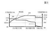
圖1描繪了根據本發明較佳實施例中,利用充電器常溫降流及高溫脈衝充電的方法,於一個完整充電過程之輸出電流(I_output)及輸出電壓(V_output)曲線。FIG. 1 depicts the output current (I_output) and output voltage (V_output) curves of a complete charging process using the method of normal temperature derating and high temperature pulse charging of a charger according to a preferred embodiment of the present invention.
圖2描繪了根據本發明較佳實施例所用充電器常溫降流及高溫脈衝充電的方法,設定轉態點(圖1),電壓25V、電流由2.5A至2.0A,經過8小時測試,其充電效率數據。Fig. 2 depicts the method of normal temperature drop and high temperature pulse charging of the charger used in accordance with the preferred embodiment of the present invention. The transition point is set (Fig. 1). The voltage is 25V and the current is from 2.5A to 2.0A. After 8 hours of testing, Charge efficiency data.
圖3描繪了根據本發明較佳實施例中用於操作圖2測試的充電器電路的功能方塊示意圖。FIG. 3 depicts a functional block diagram of the charger circuit for operating the test of FIG. 2 according to the preferred embodiment of the present invention.
圖4(A)描繪了根據本發明較佳實施例中所提出常溫降流及高溫脈衝充電方法的具體操作流程圖。FIG. 4(A) depicts a specific operation flowchart of the normal temperature down-flow and high-temperature pulse charging method according to the preferred embodiment of the present invention.
圖4(B)描繪了根據本發明較佳實施例中所提出常溫降流及高溫脈衝充電方法中浮動充電方法的具體操作流程圖。FIG. 4(B) depicts a specific operation flowchart of the floating charging method in the normal temperature down-flow and high-temperature pulse charging method according to the preferred embodiment of the present invention.
此處本發明將針對發明具體實施例及其觀點加以詳細描述,此類描述為解釋本發明之結構或步驟流程,其係供以說明之用而非用以限制本發明之申請專利範圍。因此,除說明書中之具體實施例與較佳實施例外,本發明亦可廣泛施行於其他不同的實施例中。以下藉由特定的具體實施例說明本發明之實施方式,熟悉此技術之人士可藉由本說明書所揭示之內容輕易地瞭解本發明之功效性與其優點。且本發明亦可藉由其他具體實施例加以運用及實施,本說明書所闡述之各項細節亦可基於不同需求而應用,且在不悖離本發明之精神下進行各種不同的修飾或變更。Herein, the present invention will be described in detail with respect to specific embodiments of the invention and their viewpoints. Such descriptions are used to explain the structure or step flow of the present invention, which are provided for illustrative purposes rather than to limit the scope of the patent application of the present invention. Therefore, in addition to the specific embodiments and preferred embodiments in the specification, the present invention can be widely implemented in other different embodiments. The following describes the implementation of the present invention by specific specific examples. Those familiar with this technology can easily understand the efficacy and advantages of the present invention through the contents disclosed in this specification. Moreover, the present invention can also be applied and implemented by other specific embodiments. The details described in this specification can also be applied based on different needs, and various modifications or changes can be made without departing from the spirit of the present invention.
如前所述,本發明提出一種常溫降流及高溫脈衝充電方法。具體軟體控制策略分為兩部分:(a)常溫兩段電流控制,其針對不同輸出的充電器設定不同的限流轉態點;(b)高溫脈衝充電法,其藉由充電器內部NTC(Negative Temperature Coefficient)熱敏電阻,即負溫度係數電阻,來偵測溫度,如果溫度超過設定值就會停止充電,以免充電器內部零件溫度過高。As mentioned above, the present invention proposes a normal temperature downflow and high temperature pulse charging method. The specific software control strategy is divided into two parts: (a) two-stage current control at normal temperature, which sets different current-limiting transition points for different output chargers; (b) high-temperature pulse charging method, which uses the NTC (Negative) inside the charger Temperature Coefficient) thermistor, that is, negative temperature coefficient resistor, to detect the temperature, if the temperature exceeds the set value, it will stop charging, so as not to overheat the internal parts of the charger.
具體以2.5A充電器為例子,先確認規格所需的鉛酸電池容量:BB廠牌電池、型號EB20-12、額定電池容量20AHr(C/10)、標準尺寸或電池類型2 cell。圖1顯示,充電器於一個完整充電過程之輸出電流(I_output)及輸出電壓(V_output)曲線,其中曲線101表示充電器之輸出電流(I_output)、曲線103表示充電器之輸出電壓(V_output)。整個充電程序依序包括:固定電流充電模式(constant current mode)、固定電壓模式(constant voltage mode)以及浮動充電模(float charg mode)式。根據前段敘述的方法,設定轉態點(圖1),電壓25V、電流由2.5A至2.0A,經過8小時測試,其效果如圖2所示,充電瓦數為442.984 Wh、電池瓦數為480 Wh,常溫充電效率為92.28%。Taking the 2.5A charger as an example, first confirm the lead acid battery capacity required by the specifications: BB brand battery, model EB20-12, rated battery capacity 20AHr (C/10), standard size or
圖3則顯示於操作上述測試時的電路功能方塊圖,其中AC輸入電壓(100~240Vac)經由EMI濾波與浪湧限制器(inrush limiter)301濾波整流後形成直流(DC)電壓再輸出至返馳式轉換器(flyback converter)303中的變壓器初級側的輸入端,並透過返馳式控制器(flyback controller)303a控制能量儲存,配合連接返馳式轉換器303中變壓器二次側的整流器305而可以將直流輸出(DC output)輸出,功率轉換單元30由上述EMI濾波與浪湧限制器(inrush limiter)301、返馳式轉換器(flyback converter)303、整流器305、以及返馳式控制器303a組合而成。直流輸出(DC output)輸出經由一背靠背開關電路307對電池充電,上述背靠背開關電路307是由微控制單元(MCU)309所偵測的電壓及溫度來控制電路的on/off以調節對電池輸出的電流,以一實施例而言,微控制單元309可以經由其相關腳位偵測到電池電壓、充電電流、充電器內部元件溫度等參數,以VADC、IADC等訊號饋入微控制單元309透過運算並對定電壓/定電流(CC/CV)迴路311輸出控制訊號Icon及Vcon。定電壓/定電流(CC/CV)迴路311包含低通濾波器以及CC/CV回授補償放大器(未顯示),接收由微控制單元309所輸出的控制訊號,Icon及Vcon,分別經過低通濾波器輸出至定電壓/定電流(CC/CV)迴路311中相應的電壓迴路迴授補償運算放大器與電流迴路迴授補償運算放大器(未顯示)作為輸入參考訊號,其參考輸入會與實際由整流器輸出的I、V訊號相減以得到誤差訊號,藉由負回授控制調整CP的準位,返馳式控制器303a根據CP大小調整返馳式轉換器303的輸出進而可以調節整流器305的DC輸出,上述背靠背開關電路307、微控制單元309、以及定電壓/定電流(CC/CV)迴路311組成充電控制電路31。Fig. 3 shows a functional block diagram of the circuit when operating the above test, in which the AC input voltage (100~240Vac) is filtered and rectified by EMI filtering and an inrush limiter (inrush limiter) 301 to form a direct current (DC) voltage and then output to the return The input terminal of the primary side of the transformer in the
為了更詳細說明本發明所提常溫降流及高溫脈衝充電策略,圖4(A)顯示本發明所提出常溫降流及高溫脈衝充電方法的具體操作流程圖400。流程圖400由步驟401開始,接著於步驟403(根據圖3,由微控制單元309偵測電池電壓)判斷是否完全充電,如果完全充電則停止充電程序。接著由步驟405(根據圖3,由微控制單元309偵測到的充電器元件溫度)判定充電器內部元件(晶片)的溫度是否高於100℃且持續3秒,如果高於100℃且持續3秒則進行步驟407,停止充電1分鐘,亦即高溫脈衝充電,(根據圖3,由微控制單元309控制背靠背開關電路307)然後再進行步驟409-判斷充電器電壓是否大於等於25V且持續1秒(即前面所提的限流轉態點),否則進行步驟411以定電流2.5A對電池充電(根據圖3,由微控制單元309控制定電壓/定電流迴路311以定電流模式充電),然後回到步驟405。於步驟409,如果判定充電器電壓大於等於25V且持續1秒,則進行步驟411a以定電流2.0A,亦即降流,對電池充電(根據圖3,由微控制單元309控制定電壓/定電流迴路311以定電流模式充電)。接著於步驟413,判斷充電器電壓是否大於等於29.6V且持續1秒(根據圖3,由微控制單元309偵測),否則回到步驟411a以定電流2.0A對電池充電,如果判定充電器電壓大於等於29.6V且持續1秒,則進行步驟415以定電壓29.6V對電池充電。接著於步驟417,判斷充電器電壓是否滿足浮動充電條件,即判斷充電器輸出電流IOUT_L是否大於800mA且持續60秒,如果滿足則回到步驟415繼續以定電壓29.6V對電池充電,否則進行步驟419以浮動充電檢測程序-P4對電池充電,然後於步驟421結束充電程序。In order to explain in more detail the normal temperature down-flow and high-temperature pulse charging strategy provided by the present invention, FIG. 4(A) shows a
圖4(B)顯示浮動充電方法的具體操作流程圖430,流程圖430由步驟431開始,接著於步驟433(根據圖3,微控制單元309偵測充電器輸出電流IOUT_L)判斷充電器輸出電流IOUT_L是否小於550mA且持續1秒,如果小於550mA且持續1秒則進行步驟435由定電壓充電模式轉換為浮動充電模式,接著於步驟437(根據圖3,微控制單元309偵測充電器輸出電流IOUT_L)判斷充電器輸出電流IOUT_L是否小於60mA且持續300微秒,否則就回到P5(即圖4A中步驟417)。於步驟437,如果判斷充電器輸出電流IOUT_L是小於60mA且持續300微秒則由微控制器設定停止充電模式(CHON=0),接著結束充電程序421。4(B) shows a
綜上所述,本發明所提出的常溫降流及高溫脈衝充電方法除了具有降低充電器零件溫度以及增加產品可靠度的優點外,最顯著的效果是在滿足50℃環境溫度要求上相對較為簡單,可以減少散熱片以及散熱膠需求。In summary, in addition to the advantages of reducing the temperature of the charger parts and increasing the reliability of the product, the method of normal temperature down-current and high-temperature pulse charging proposed by the present invention is relatively simple in meeting the requirement of 50°C ambient temperature , Can reduce the need for heat sink and heat dissipation glue.
在不脫離本文範疇之情況下,可對上述常溫降流及高溫脈衝充電方法做出改變。因此,應當注意,包含在以上描述中並且在附圖中示出之內容應當被解釋為說明性的而非限制性之意義。以下申請專利範圍旨在涵蓋本文中所描述之所有一般特徵及特定特徵,以及本發明常溫降流及高溫脈衝充電方法之範疇的所有陳述,其在語言上可被說成落在其間。Without departing from the scope of this article, changes can be made to the above normal temperature down-flow and high-temperature pulse charging methods. Therefore, it should be noted that the contents included in the above description and shown in the drawings should be interpreted as illustrative rather than limiting. The scope of the following patent applications is intended to cover all the general and specific features described in this document, as well as all statements in the scope of the normal temperature down-flow and high-temperature pulse charging method of the present invention, which can be said to fall in the language.
400‧‧‧常溫降流及高溫脈衝充電方法的具體操作流程圖400 ‧‧‧Normal temperature downflow and high temperature pulse charging method specific operation flowchart
401、403、405、407、409、411、411a、413、415、417、419、421‧‧‧步驟401, 403, 405, 407, 409, 411, 411a, 413, 415, 417, 419, 421‧‧‧ steps
Claims (9)
Translated fromChinesePriority Applications (3)
| Application Number | Priority Date | Filing Date | Title |
|---|---|---|---|
| TW108131731ATWI695564B (en) | 2019-09-03 | 2019-09-03 | Temperature dependent current and pulse controlled charging method for a battery charger |
| CN201910984423.4ACN112448438B (en) | 2019-09-03 | 2019-10-16 | Normal temperature drop current and high temperature pulse charging method of battery charger |
| US16/705,250US11349325B2 (en) | 2019-09-03 | 2019-12-06 | Temperature dependent current and pulse controlled charging method for a battery charger |
Applications Claiming Priority (1)
| Application Number | Priority Date | Filing Date | Title |
|---|---|---|---|
| TW108131731ATWI695564B (en) | 2019-09-03 | 2019-09-03 | Temperature dependent current and pulse controlled charging method for a battery charger |
Publications (2)
| Publication Number | Publication Date |
|---|---|
| TWI695564Btrue TWI695564B (en) | 2020-06-01 |
| TW202112027A TW202112027A (en) | 2021-03-16 |
Family
ID=72176090
Family Applications (1)
| Application Number | Title | Priority Date | Filing Date |
|---|---|---|---|
| TW108131731ATWI695564B (en) | 2019-09-03 | 2019-09-03 | Temperature dependent current and pulse controlled charging method for a battery charger |
Country Status (3)
| Country | Link |
|---|---|
| US (1) | US11349325B2 (en) |
| CN (1) | CN112448438B (en) |
| TW (1) | TWI695564B (en) |
Families Citing this family (1)
| Publication number | Priority date | Publication date | Assignee | Title |
|---|---|---|---|---|
| TW202137620A (en)* | 2020-03-25 | 2021-10-01 | 飛宏科技股份有限公司 | Dual port battery charging system for battery pack and the method thereof |
Citations (6)
| Publication number | Priority date | Publication date | Assignee | Title |
|---|---|---|---|---|
| WO2005015252A1 (en)* | 2003-06-27 | 2005-02-17 | The Furukawa Electric Co., Ltd. | Method for judging deterioration of accumulator, method for measuring secondary cell internal impedance, device for measuring secondary cell internal impedance, device for judging deterioration of secondary cell, and power source system |
| TW201803243A (en)* | 2016-02-05 | 2018-01-16 | 廣東歐珀移動通信有限公司 | System and method for charging terminal and power adapter |
| TW201832441A (en)* | 2017-02-24 | 2018-09-01 | 大陸商Oppo廣東移動通信有限公司 | Equalizing circuit, device to be charged and Charging control method |
| US20180295706A1 (en)* | 2006-03-28 | 2018-10-11 | Wireless Environment, Llc | Wireless lighting system with camera operation |
| TW201916565A (en)* | 2017-09-22 | 2019-04-16 | 大陸商Oppo廣東移動通信有限公司 | Power supply circuit, power supply device and control method |
| US20190121338A1 (en)* | 2016-05-09 | 2019-04-25 | Strong Force Iot Portfolio 2016, Llc | Systems and methods utilizing routing schemes to optimize data collection |
Family Cites Families (15)
| Publication number | Priority date | Publication date | Assignee | Title |
|---|---|---|---|---|
| JP3430264B2 (en)* | 1992-06-23 | 2003-07-28 | ソニー株式会社 | Charging device |
| JP3484251B2 (en)* | 1995-02-06 | 2004-01-06 | 本田技研工業株式会社 | Battery charging control device for electric vehicles |
| KR100406796B1 (en)* | 2001-10-17 | 2003-11-21 | 삼성에스디아이 주식회사 | Method to precisely estimate effective full-discharge capacity of secondary battery |
| US7834591B2 (en)* | 2006-02-16 | 2010-11-16 | Summit Microelectronics, Inc. | Switching battery charging systems and methods |
| JP4884045B2 (en)* | 2006-03-21 | 2012-02-22 | 三洋電機株式会社 | Rechargeable battery charging method |
| JP5131189B2 (en)* | 2006-03-24 | 2013-01-30 | 日本電気株式会社 | Charging system, charging control program and portable terminal |
| US9337684B2 (en)* | 2008-05-06 | 2016-05-10 | Johnson Controls Technology Company | Battery charging device and method |
| CN101931247B (en)* | 2009-06-26 | 2013-07-24 | 华硕电脑股份有限公司 | Charging system and battery power management method |
| CN102651565B (en)* | 2011-02-25 | 2015-05-13 | 凹凸电子(武汉)有限公司 | Battery pack charging management method and device, charger and battery pack managing system |
| US9035623B1 (en)* | 2013-01-23 | 2015-05-19 | Qnovo Inc. | Monitor and control circuitry for charging a battery/cell, and methods of operating same |
| US8907631B1 (en)* | 2013-07-31 | 2014-12-09 | Qnovo Inc. | Adaptive charging technique and circuitry for a battery/cell using multiple charge circuits and temperature data |
| US9853477B2 (en)* | 2013-11-12 | 2017-12-26 | Grenotek Integrated, Inc. | Systems and methods of adaptive battery charging |
| SE541171C2 (en)* | 2015-03-16 | 2019-04-23 | Ctek Sweden Ab | A method for operating a battery charger, and a battery charger |
| US9966781B2 (en)* | 2015-12-28 | 2018-05-08 | Silicon Laboratories Inc. | Apparatus for battery charger with controlled charge current and associated methods |
| US10063084B2 (en)* | 2015-12-28 | 2018-08-28 | Silicon Laboratories Inc. | Apparatus for digital battery charger and associated methods |
- 2019
- 2019-09-03TWTW108131731Apatent/TWI695564B/enactive
- 2019-10-16CNCN201910984423.4Apatent/CN112448438B/enactiveActive
- 2019-12-06USUS16/705,250patent/US11349325B2/enactiveActive
Patent Citations (6)
| Publication number | Priority date | Publication date | Assignee | Title |
|---|---|---|---|---|
| WO2005015252A1 (en)* | 2003-06-27 | 2005-02-17 | The Furukawa Electric Co., Ltd. | Method for judging deterioration of accumulator, method for measuring secondary cell internal impedance, device for measuring secondary cell internal impedance, device for judging deterioration of secondary cell, and power source system |
| US20180295706A1 (en)* | 2006-03-28 | 2018-10-11 | Wireless Environment, Llc | Wireless lighting system with camera operation |
| TW201803243A (en)* | 2016-02-05 | 2018-01-16 | 廣東歐珀移動通信有限公司 | System and method for charging terminal and power adapter |
| US20190121338A1 (en)* | 2016-05-09 | 2019-04-25 | Strong Force Iot Portfolio 2016, Llc | Systems and methods utilizing routing schemes to optimize data collection |
| TW201832441A (en)* | 2017-02-24 | 2018-09-01 | 大陸商Oppo廣東移動通信有限公司 | Equalizing circuit, device to be charged and Charging control method |
| TW201916565A (en)* | 2017-09-22 | 2019-04-16 | 大陸商Oppo廣東移動通信有限公司 | Power supply circuit, power supply device and control method |
Also Published As
| Publication number | Publication date |
|---|---|
| US20210066946A1 (en) | 2021-03-04 |
| CN112448438B (en) | 2023-02-03 |
| TW202112027A (en) | 2021-03-16 |
| US11349325B2 (en) | 2022-05-31 |
| CN112448438A (en) | 2021-03-05 |
Similar Documents
| Publication | Publication Date | Title |
|---|---|---|
| AU2017215242B2 (en) | Adaptor and charging control method | |
| CN102447283B (en) | Charging system and charging method | |
| US9479060B2 (en) | Control circuit, battery power supply device and control method | |
| Chen et al. | New digital-controlled technique for battery charger with constant current and voltage control without current feedback | |
| EP3258586B1 (en) | Power converter with load switch fault protection | |
| TWI411202B (en) | Controller for power converter and method for controlling power converter | |
| US11837887B2 (en) | Charging integrated circuit and operating method | |
| US11258281B2 (en) | Intelligence AC to DC maximum power management method of a battery charger | |
| JP5919506B2 (en) | Rechargeable electrical equipment | |
| CN110504728A (en) | A battery charging system, method, device, computer equipment and storage medium | |
| CN201266840Y (en) | DC power supply manager, power supply translation circuit and battery bag | |
| CN106786886B (en) | wireless charging system charging method based on load identification technology | |
| CN110571920A (en) | An emergency power switching main control circuit and charging method | |
| WO2018192485A1 (en) | Integrated circuit, for realizing zero power consumption standby, of switching power supply | |
| WO2005076099A1 (en) | Enabling circuit for avoiding negative voltage transients | |
| TWI695564B (en) | Temperature dependent current and pulse controlled charging method for a battery charger | |
| CN103457314B (en) | A kind of switching mode single lithium battery charging and step-up discharge control chip | |
| TWI683502B (en) | Charging device and operating method thereof | |
| US20170066339A1 (en) | Charging apparatus and vehicle | |
| CN102064566B (en) | Charging device, electronic device and charging method | |
| Dearborn | Charging Lithium-Ion Batteries: Not All Charging Systems Are Created Equal | |
| CN106787664A (en) | Soft starting circuit | |
| CN210273531U (en) | Charging circuit, charging equipment and terminal | |
| CN210327061U (en) | A lithium battery charger circuit control system | |
| CN203813495U (en) | A charger that can automatically shut down |