TWI691388B - Substrate processing tool - Google Patents
Substrate processing toolDownload PDFInfo
- Publication number
- TWI691388B TWI691388BTW106131822ATW106131822ATWI691388BTW I691388 BTWI691388 BTW I691388BTW 106131822 ATW106131822 ATW 106131822ATW 106131822 ATW106131822 ATW 106131822ATW I691388 BTWI691388 BTW I691388B
- Authority
- TW
- Taiwan
- Prior art keywords
- arm
- scara
- axis
- arms
- end effector
- Prior art date
Links
- 239000000758substrateSubstances0.000titleclaimsabstractdescription199
- 238000012545processingMethods0.000titleclaimsabstractdescription176
- 239000012636effectorSubstances0.000claimsabstractdescription198
- 210000000245forearmAnatomy0.000claimsdescription114
- 210000000707wristAnatomy0.000claimsdescription35
- 238000012546transferMethods0.000abstractdescription28
- 230000005540biological transmissionEffects0.000description109
- 230000033001locomotionEffects0.000description39
- 238000007789sealingMethods0.000description31
- 230000008878couplingEffects0.000description9
- 238000010168coupling processMethods0.000description9
- 238000005859coupling reactionMethods0.000description9
- 238000010586diagramMethods0.000description9
- 230000009471actionEffects0.000description6
- 238000000034methodMethods0.000description5
- 230000008569processEffects0.000description5
- 101100323157Arabidopsis thaliana LAP1 geneProteins0.000description4
- 238000009434installationMethods0.000description4
- 230000013011matingEffects0.000description4
- 210000000323shoulder jointAnatomy0.000description4
- 238000001514detection methodMethods0.000description3
- 101100476713Gallus gallus SAX1 geneProteins0.000description2
- 101000971703Homo sapiens Kinesin-like protein KIF1CProteins0.000description2
- 101000979579Homo sapiens NK1 transcription factor-related protein 1Proteins0.000description2
- 102100021525Kinesin-like protein KIF1CHuman genes0.000description2
- 101100460492Mus musculus Nkx1-2 geneProteins0.000description2
- 230000006698inductionEffects0.000description2
- 230000001939inductive effectEffects0.000description2
- 239000011261inert gasSubstances0.000description2
- 238000002955isolationMethods0.000description2
- 239000011553magnetic fluidSubstances0.000description2
- 239000000463materialSubstances0.000description2
- 230000003287optical effectEffects0.000description2
- 230000004308accommodationEffects0.000description1
- 238000009825accumulationMethods0.000description1
- 230000000903blocking effectEffects0.000description1
- 230000008859changeEffects0.000description1
- 238000004140cleaningMethods0.000description1
- 150000001875compoundsChemical class0.000description1
- 238000004320controlled atmosphereMethods0.000description1
- 230000009977dual effectEffects0.000description1
- 230000000694effectsEffects0.000description1
- 238000005530etchingMethods0.000description1
- 230000006870functionEffects0.000description1
- 230000002452interceptive effectEffects0.000description1
- 238000005468ion implantationMethods0.000description1
- 210000001503jointAnatomy0.000description1
- 230000007774longtermEffects0.000description1
- 238000005259measurementMethods0.000description1
- 230000007246mechanismEffects0.000description1
- 238000012986modificationMethods0.000description1
- 230000004048modificationEffects0.000description1
- 239000013618particulate matterSubstances0.000description1
- 238000005498polishingMethods0.000description1
- 230000002441reversible effectEffects0.000description1
- 239000004065semiconductorSubstances0.000description1
- 238000006467substitution reactionMethods0.000description1
Images


Classifications
- H—ELECTRICITY
- H01—ELECTRIC ELEMENTS
- H01L—SEMICONDUCTOR DEVICES NOT COVERED BY CLASS H10
- H01L21/00—Processes or apparatus adapted for the manufacture or treatment of semiconductor or solid state devices or of parts thereof
- H01L21/67—Apparatus specially adapted for handling semiconductor or electric solid state devices during manufacture or treatment thereof; Apparatus specially adapted for handling wafers during manufacture or treatment of semiconductor or electric solid state devices or components ; Apparatus not specifically provided for elsewhere
- H01L21/677—Apparatus specially adapted for handling semiconductor or electric solid state devices during manufacture or treatment thereof; Apparatus specially adapted for handling wafers during manufacture or treatment of semiconductor or electric solid state devices or components ; Apparatus not specifically provided for elsewhere for conveying, e.g. between different workstations
- H01L21/67703—Apparatus specially adapted for handling semiconductor or electric solid state devices during manufacture or treatment thereof; Apparatus specially adapted for handling wafers during manufacture or treatment of semiconductor or electric solid state devices or components ; Apparatus not specifically provided for elsewhere for conveying, e.g. between different workstations between different workstations
- H01L21/67706—Mechanical details, e.g. roller, belt
- H—ELECTRICITY
- H01—ELECTRIC ELEMENTS
- H01L—SEMICONDUCTOR DEVICES NOT COVERED BY CLASS H10
- H01L21/00—Processes or apparatus adapted for the manufacture or treatment of semiconductor or solid state devices or of parts thereof
- H01L21/67—Apparatus specially adapted for handling semiconductor or electric solid state devices during manufacture or treatment thereof; Apparatus specially adapted for handling wafers during manufacture or treatment of semiconductor or electric solid state devices or components ; Apparatus not specifically provided for elsewhere
- H01L21/677—Apparatus specially adapted for handling semiconductor or electric solid state devices during manufacture or treatment thereof; Apparatus specially adapted for handling wafers during manufacture or treatment of semiconductor or electric solid state devices or components ; Apparatus not specifically provided for elsewhere for conveying, e.g. between different workstations
- H01L21/67739—Apparatus specially adapted for handling semiconductor or electric solid state devices during manufacture or treatment thereof; Apparatus specially adapted for handling wafers during manufacture or treatment of semiconductor or electric solid state devices or components ; Apparatus not specifically provided for elsewhere for conveying, e.g. between different workstations into and out of processing chamber
- H01L21/67742—Mechanical parts of transfer devices
- B—PERFORMING OPERATIONS; TRANSPORTING
- B25—HAND TOOLS; PORTABLE POWER-DRIVEN TOOLS; MANIPULATORS
- B25J—MANIPULATORS; CHAMBERS PROVIDED WITH MANIPULATION DEVICES
- B25J11/00—Manipulators not otherwise provided for
- B25J11/0095—Manipulators transporting wafers
- B—PERFORMING OPERATIONS; TRANSPORTING
- B25—HAND TOOLS; PORTABLE POWER-DRIVEN TOOLS; MANIPULATORS
- B25J—MANIPULATORS; CHAMBERS PROVIDED WITH MANIPULATION DEVICES
- B25J18/00—Arms
- B25J18/02—Arms extensible
- B25J18/04—Arms extensible rotatable
- B—PERFORMING OPERATIONS; TRANSPORTING
- B25—HAND TOOLS; PORTABLE POWER-DRIVEN TOOLS; MANIPULATORS
- B25J—MANIPULATORS; CHAMBERS PROVIDED WITH MANIPULATION DEVICES
- B25J9/00—Programme-controlled manipulators
- B25J9/02—Programme-controlled manipulators characterised by movement of the arms, e.g. cartesian coordinate type
- B25J9/04—Programme-controlled manipulators characterised by movement of the arms, e.g. cartesian coordinate type by rotating at least one arm, excluding the head movement itself, e.g. cylindrical coordinate type or polar coordinate type
- B25J9/041—Cylindrical coordinate type
- B25J9/042—Cylindrical coordinate type comprising an articulated arm
- B25J9/043—Cylindrical coordinate type comprising an articulated arm double selective compliance articulated robot arms [SCARA]
- Y—GENERAL TAGGING OF NEW TECHNOLOGICAL DEVELOPMENTS; GENERAL TAGGING OF CROSS-SECTIONAL TECHNOLOGIES SPANNING OVER SEVERAL SECTIONS OF THE IPC; TECHNICAL SUBJECTS COVERED BY FORMER USPC CROSS-REFERENCE ART COLLECTIONS [XRACs] AND DIGESTS
- Y10—TECHNICAL SUBJECTS COVERED BY FORMER USPC
- Y10S—TECHNICAL SUBJECTS COVERED BY FORMER USPC CROSS-REFERENCE ART COLLECTIONS [XRACs] AND DIGESTS
- Y10S901/00—Robots
- Y10S901/14—Arm movement, spatial
- Y10S901/15—Jointed arm
- Y—GENERAL TAGGING OF NEW TECHNOLOGICAL DEVELOPMENTS; GENERAL TAGGING OF CROSS-SECTIONAL TECHNOLOGIES SPANNING OVER SEVERAL SECTIONS OF THE IPC; TECHNICAL SUBJECTS COVERED BY FORMER USPC CROSS-REFERENCE ART COLLECTIONS [XRACs] AND DIGESTS
- Y10—TECHNICAL SUBJECTS COVERED BY FORMER USPC
- Y10S—TECHNICAL SUBJECTS COVERED BY FORMER USPC CROSS-REFERENCE ART COLLECTIONS [XRACs] AND DIGESTS
- Y10S901/00—Robots
- Y10S901/27—Arm part
- Y—GENERAL TAGGING OF NEW TECHNOLOGICAL DEVELOPMENTS; GENERAL TAGGING OF CROSS-SECTIONAL TECHNOLOGIES SPANNING OVER SEVERAL SECTIONS OF THE IPC; TECHNICAL SUBJECTS COVERED BY FORMER USPC CROSS-REFERENCE ART COLLECTIONS [XRACs] AND DIGESTS
- Y10—TECHNICAL SUBJECTS COVERED BY FORMER USPC
- Y10T—TECHNICAL SUBJECTS COVERED BY FORMER US CLASSIFICATION
- Y10T74/00—Machine element or mechanism
- Y10T74/20—Control lever and linkage systems
- Y10T74/20207—Multiple controlling elements for single controlled element
- Y10T74/20305—Robotic arm
- Y10T74/20329—Joint between elements
Landscapes
- Engineering & Computer Science (AREA)
- Robotics (AREA)
- Mechanical Engineering (AREA)
- Condensed Matter Physics & Semiconductors (AREA)
- General Physics & Mathematics (AREA)
- Manufacturing & Machinery (AREA)
- Computer Hardware Design (AREA)
- Microelectronics & Electronic Packaging (AREA)
- Power Engineering (AREA)
- Physics & Mathematics (AREA)
- Container, Conveyance, Adherence, Positioning, Of Wafer (AREA)
- Manipulator (AREA)
- Polarising Elements (AREA)
- Manufacturing Of Printed Wiring (AREA)
- Cleaning Or Drying Semiconductors (AREA)
Abstract
Description
Translated fromChinese本申請案是西元2011年3月11日提出申請之美國專利臨時申請案第61/451,912號及西元2010年11月10提出申請之美國專利臨時申請案第61/412,218號的非臨時申請案,該上述案件的全部內容藉此參照併入本文。This application is a non-provisional application of US Patent Provisional Application No. 61/451,912 filed on March 11, 2011 and US Patent Provisional Application No. 61/412,218 filed on November 10, 2010. The entire contents of the above case are hereby incorporated by reference.
範例性實施例基本上是有關於基板處理裝置,特別是有關於基板輸送裝置。The exemplary embodiment basically relates to a substrate processing apparatus, and particularly relates to a substrate conveying apparatus.
一般而言,在基板處理系統中,具有多個手臂的輸送機器手臂的手臂的旋轉是互相連接在一起的,因此當一手臂旋轉時,其他的手臂也會跟著旋轉。輸送機器手臂的末端作用器通常是位在不同的平面上,因此常常會發生需要利用輸送機器手臂或固持站的Z軸能力來將基板快速地換至或移出固持位置(例如一末端作用器徑向通過另一末端作用器上方/下方,以使得在將一基板自一固持站取出 時,另一基板則同時放置至該固持站)。Generally speaking, in a substrate processing system, the rotations of the arms of a conveyor robot arm with multiple arms are connected to each other, so when one arm rotates, the other arms also follow. The end effector of the transport robot arm is usually located on a different plane, so it often happens that the Z axis capability of the transport robot arm or holding station is needed to quickly change the substrate to or out of the holding position (for example, an end effector diameter To pass above/below the other end effector, so that when one substrate is taken out from a holding station, the other substrate is simultaneously placed on the holding station).
將基板輸送機器手臂手臂的旋轉動作解構,以使得每一手臂能夠獨立運作,將會是很有用。It will be useful to deconstruct the rotation of the arm of the substrate transport robot arm so that each arm can operate independently.
所揭示之實施例的前述態樣及其他特點將會在下面的說明中配合所附圖式來解釋。The foregoing aspects and other features of the disclosed embodiments will be explained in conjunction with the accompanying drawings in the following description.
100‧‧‧基板處理裝置100‧‧‧Substrate processing device
100’‧‧‧群集式設備100’‧‧‧ cluster equipment
105‧‧‧氛圍段105‧‧‧Ambient Section
110‧‧‧氛圍密封段110‧‧‧ Atmosphere sealing section
115‧‧‧基板固持卡閘115‧‧‧Basic Card Holder
120‧‧‧氛圍機器手臂120‧‧‧Ambient Robot Arm
125‧‧‧處理模組125‧‧‧Processing module
130‧‧‧輸送機器手臂130‧‧‧Transport robot arm
135‧‧‧負載鎖135‧‧‧ load lock
140‧‧‧負載鎖140‧‧‧ load lock
150‧‧‧驅動段150‧‧‧Drive section
155A‧‧‧手臂155A‧‧‧arm
155B‧‧‧手臂155B‧‧‧arm
155EA‧‧‧末端作用器155EA‧‧‧End effector
155EB‧‧‧末端作用器155EB‧‧‧End effector
155EH‧‧‧末端作用器155EH‧‧‧End effector
155EV‧‧‧末端作用器155EV‧‧‧End effector
155FA‧‧‧前臂155FA‧‧‧Forearm
155FB‧‧‧前臂155FB‧‧‧Forearm
155LFA‧‧‧連桿組155LFA‧‧‧Link set
155LFB‧‧‧連桿組155LFB‧‧‧Link set
155LUA‧‧‧連桿組155LUA‧‧‧Link set
155LUB‧‧‧連桿組155LUB‧‧‧Link set
155UA‧‧‧上臂155UA‧‧‧ Upper arm
155UB‧‧‧上臂155UB‧‧‧ Upper arm
162‧‧‧對準器162‧‧‧Aligner
170‧‧‧控制器170‧‧‧Controller
173‧‧‧處理器173‧‧‧ processor
175‧‧‧中心腔室175‧‧‧ Central chamber
178‧‧‧記憶體178‧‧‧ memory
180‧‧‧開口180‧‧‧ opening
185‧‧‧開口185‧‧‧ opening
215‧‧‧基板215‧‧‧ substrate
300‧‧‧四同軸驅動軸桿總成300‧‧‧Four coaxial drive shaft assembly
301‧‧‧驅動軸桿301‧‧‧Drive shaft
302‧‧‧驅動軸桿302‧‧‧Drive shaft
303‧‧‧驅動軸桿303‧‧‧ drive shaft
304‧‧‧驅動軸桿304‧‧‧ drive shaft
310‧‧‧殼體310‧‧‧Housing
312‧‧‧Z軸馬達312‧‧‧Z axis motor
342‧‧‧馬達342‧‧‧Motor
342R‧‧‧轉子342R‧‧‧Rotor
342S‧‧‧定子342S‧‧‧Stator
344‧‧‧馬達344‧‧‧Motor
344R‧‧‧轉子344R‧‧‧Rotor
344S‧‧‧定子344S‧‧‧Stator
346‧‧‧馬達346‧‧‧Motor
346R‧‧‧轉子346R‧‧‧Rotor
346S‧‧‧定子346S‧‧‧Stator
348‧‧‧馬達348‧‧‧Motor
348R‧‧‧轉子348R‧‧‧Rotor
348S‧‧‧定子348S‧‧‧Stator
350‧‧‧軸承350‧‧‧bearing
351‧‧‧軸承351‧‧‧bearing
352‧‧‧軸承352‧‧‧bearing
353‧‧‧軸承353‧‧‧bearing
362‧‧‧套筒362‧‧‧Sleeve
371‧‧‧位置感應器371‧‧‧Position sensor
372‧‧‧位置感應器372‧‧‧Position sensor
373‧‧‧位置感應器373‧‧‧Position sensor
374‧‧‧位置感應器374‧‧‧Position sensor
380‧‧‧滑輪380‧‧‧Pulley
381‧‧‧桿381‧‧‧
382‧‧‧滑輪382‧‧‧Pulley
382S‧‧‧軸桿382S‧‧‧Shaft
383‧‧‧滑輪383‧‧‧Pulley
384‧‧‧滑輪384‧‧‧Pulley
385‧‧‧桿385‧‧‧
386‧‧‧滑輪386‧‧‧Pulley
387‧‧‧滑輪387‧‧‧Pulley
387S‧‧‧軸桿387S‧‧‧Shaft
388‧‧‧桿388‧‧‧
389‧‧‧滑輪389‧‧‧Pulley
390‧‧‧傳動構件390‧‧‧ Transmission components
391‧‧‧傳動構件391‧‧‧ Transmission components
392‧‧‧傳動構件392‧‧‧ Transmission components
393‧‧‧傳動構件393‧‧‧ Transmission components
398‧‧‧桿398‧‧‧
399‧‧‧滑輪399‧‧‧Pulley
400‧‧‧傳輸腔室400‧‧‧Transmission chamber
400P‧‧‧埠口400P‧‧‧port
530‧‧‧輸送機械手530‧‧‧Conveyor manipulator
555A‧‧‧手臂555A‧‧‧arm
555B‧‧‧手臂555B‧‧‧arm
555EA‧‧‧末端作用器555EA‧‧‧End effector
555EB‧‧‧末端作用器555EB‧‧‧End effector
555UA‧‧‧上臂555UA‧‧‧ Upper arm
555UB‧‧‧上臂555UB‧‧‧ Upper arm
555FA‧‧‧前臂555FA‧‧‧Forearm
555FB‧‧‧前臂555FB‧‧‧Forearm
582S‧‧‧軸桿582S‧‧‧Shaft
587S‧‧‧軸桿587S‧‧‧Shaft
634‧‧‧三軸驅動系統634‧‧‧Three-axis drive system
641‧‧‧驅動軸桿總成641‧‧‧Drive shaft assembly
642‧‧‧馬達642‧‧‧Motor
644‧‧‧馬達644‧‧‧Motor
646‧‧‧馬達646‧‧‧Motor
648A‧‧‧定子648A‧‧‧Stator
648B‧‧‧定子648B‧‧‧Stator
648C‧‧‧定子648C‧‧‧Stator
650A‧‧‧驅動軸桿650A‧‧‧Drive shaft
650B‧‧‧驅動軸桿650B‧‧‧Drive shaft
650C‧‧‧驅動軸桿650C‧‧‧Drive shaft
652‧‧‧殼體652‧‧‧Housing
660A‧‧‧轉子660A‧‧‧Rotor
660B‧‧‧轉子660B‧‧‧Rotor
660C‧‧‧轉子660C‧‧‧Rotor
662‧‧‧套筒662‧‧‧Sleeve
664‧‧‧位置感應器664‧‧‧Position sensor
670‧‧‧滑輪670‧‧‧Pulley
670A‧‧‧第一滑輪段670A‧‧‧The first pulley section
670B‧‧‧第二滑輪段670B‧‧‧Second pulley block
1001‧‧‧處理站1001‧‧‧ processing station
1002‧‧‧感應器1002‧‧‧Sensor
1003‧‧‧感應器1003‧‧‧sensor
1030E‧‧‧末端作用器1030E‧‧‧End effector
1030‧‧‧機器手臂1030‧‧‧Robot arm
1300‧‧‧驅動系統1300‧‧‧ drive system
1300H‧‧‧馬達殼體1300H‧‧‧Motor housing
1300X‧‧‧固定突緣1300X‧‧‧Fixed flange
1301‧‧‧偏置馬達配置1301‧‧‧Offset motor configuration
1310‧‧‧同軸式主軸配置1310‧‧‧Coaxial spindle configuration
1311‧‧‧驅動軸桿1311‧‧‧ drive shaft
1312‧‧‧驅動軸桿1312‧‧‧Drive shaft
1313‧‧‧驅動軸桿1313‧‧‧Drive shaft
1314‧‧‧驅動軸桿1314‧‧‧ drive shaft
1320‧‧‧軸承1320‧‧‧Bearing
1320A‧‧‧外軸承環1320A‧‧‧Outer bearing ring
1320B‧‧‧內軸承環1320B‧‧‧Inner bearing ring
1321‧‧‧軸承1321‧‧‧Bearing
1321A‧‧‧外軸承環1321A‧‧‧Outer bearing ring
1321B‧‧‧內軸承環1321B‧‧‧Inner bearing ring
1322‧‧‧軸承1322‧‧‧Bearing
1322A‧‧‧外軸承環1322A‧‧‧Outer bearing ring
1322B‧‧‧內軸承環1322B‧‧‧Inner bearing ring
1323‧‧‧軸承1323‧‧‧bearing
1323A‧‧‧外軸承環1323A‧‧‧Outer bearing ring
1323B‧‧‧內軸承環1323B‧‧‧Inner bearing ring
1403‧‧‧馬達1403‧‧‧Motor
1403R‧‧‧轉子1403R‧‧‧Rotor
1403S‧‧‧定子1403S‧‧‧Stator
1404‧‧‧馬達1404‧‧‧Motor
1404R‧‧‧轉子1404R‧‧‧Rotor
1404S‧‧‧定子1404S‧‧‧Stator
1501‧‧‧路徑1501‧‧‧ Path
1502‧‧‧路徑1502‧‧‧path
1610‧‧‧框架1610‧‧‧Frame
1610S‧‧‧配接段1610S‧‧‧Match section
1615‧‧‧舉升連桿1615‧‧‧Lift connecting rod
1615A‧‧‧孔洞1615A‧‧‧hole
1635‧‧‧驅動軸線接合部1635‧‧‧ drive axis joint
1666‧‧‧箭號1666‧‧‧Arrow
1669‧‧‧樞轉連桿1669‧‧‧Pivot link
1669E1‧‧‧第一末端1669E1‧‧‧The first end
1669E2‧‧‧第二末端1669E2‧‧‧second end
1669P1‧‧‧樞轉點1669P1‧‧‧ pivot point
1672‧‧‧基座構件段1672‧‧‧Base member section
1672’‧‧‧基座構件段1672’‧‧‧Base member section
1672S‧‧‧安裝段1672S‧‧‧Installation section
1673‧‧‧框架1673‧‧‧frame
1673S‧‧‧支座表面1673S‧‧‧Support surface
1678‧‧‧基座構件段1678‧‧‧Base member section
1678’‧‧‧基座構件段1678’‧‧‧ Base member section
1678”‧‧‧基座構件段1678”‧‧‧Base member section
1678A‧‧‧第一部位1678A‧‧‧The first part
1678B‧‧‧第二部位1678B‧‧‧Second part
1681A‧‧‧扣件孔1681A‧‧‧ fastener hole
1681B‧‧‧扣件孔1681B‧‧‧ fastener hole
1681F‧‧‧扣件1681F‧‧‧Fastener
1686‧‧‧Z驅動器1686‧‧‧Z drive
1686M‧‧‧連接構件1686M‧‧‧Connecting member
1687‧‧‧Z軸驅動器1687‧‧‧Z axis driver
1699‧‧‧驅動段1699‧‧‧Drive section
1699’‧‧‧驅動器1699’‧‧‧Drive
1750‧‧‧手臂1750‧‧‧arm
1751‧‧‧手臂1751‧‧‧arm
1760‧‧‧單軸驅動器1760‧‧‧single axis drive
1770‧‧‧肩滑輪1770‧‧‧Shoulder pulley
1770E‧‧‧延伸部1770E‧‧‧Extension
1775‧‧‧孔洞1775‧‧‧hole
1800‧‧‧處理設備1800‧‧‧ processing equipment
1801‧‧‧傳輸裝置1801‧‧‧Transmission device
1801D‧‧‧驅動段1801D‧‧‧Drive section
1810‧‧‧連桿組手臂1810‧‧‧Link arm
1850‧‧‧基座構件1850‧‧‧Base member
1860‧‧‧手臂1860‧‧‧arm
1861‧‧‧手臂1861‧‧‧arm
1900‧‧‧雙手臂輸送裝置1900‧‧‧Double arm conveyor
1901‧‧‧手臂1901‧‧‧arm
1901EE1‧‧‧末端作用器1901EE1‧‧‧End effector
1901EE2‧‧‧末端作用器1901EE2‧‧‧End effector
1901FA‧‧‧前臂1901FA‧‧‧Forearm
1901J‧‧‧接合部1901J‧‧‧Joint
1901P1‧‧‧滑輪1901P1‧‧‧Pulley
1901P2‧‧‧滑輪1901P2‧‧‧Pulley
1901P3‧‧‧滑輪1901P3‧‧‧ Pulley
1901P4‧‧‧滑輪1901P4‧‧‧Pulley
1901SJ‧‧‧肩接合部1901SJ‧‧‧Shoulder joint
1901UA‧‧‧上臂1901UA‧‧‧Upper arm
1902‧‧‧手臂1902‧‧‧arm
1902EE‧‧‧末端作用器1902EE‧‧‧End effector
1902FA‧‧‧前臂1902FA‧‧‧Forearm
1902P1‧‧‧滑輪1902P1‧‧‧Pulley
1902P2‧‧‧滑輪1902P2‧‧‧Pulley
1902UA‧‧‧上臂1902UA‧‧‧Upper arm
1910‧‧‧驅動系統1910‧‧‧Drive system
1911‧‧‧控制器1911‧‧‧Controller
1920‧‧‧馬達1920‧‧‧Motor
1920D1‧‧‧外側軸桿1920D1‧‧‧Outside shaft
1920D2‧‧‧內側軸桿1920D2‧‧‧Inner shaft
1930‧‧‧馬達1930‧‧‧Motor
1930D1‧‧‧外側軸桿1930D1‧‧‧Outside shaft
1930D2‧‧‧內側軸桿1930D2‧‧‧Inner shaft
1940‧‧‧舉升框架1940‧‧‧Lifting frame
1940D‧‧‧Z驅動器1940D‧‧‧Z drive
1960‧‧‧傳動裝置1960‧‧‧ Transmission
1961‧‧‧傳動裝置1961‧‧‧ Transmission
1962‧‧‧傳動裝置1962‧‧‧ Transmission
1963‧‧‧傳動裝置1963‧‧‧ Transmission
1990‧‧‧包容區域1990‧‧‧ Inclusive area
1998‧‧‧伸出/縮回軸線1998‧‧‧Extend/retract axis
1999‧‧‧箭號1999‧‧‧Arrow
2000‧‧‧基板處理裝置2000‧‧‧Substrate processing device
2005‧‧‧氛圍段2005‧‧‧Ambient Section
2010‧‧‧氛圍密封段2010‧‧‧Ambient Sealing Section
2015‧‧‧負載埠口2015‧‧‧Load port
2020‧‧‧機器手臂2020‧‧‧Robot
2025‧‧‧處理模組2025‧‧‧Processing module
2030‧‧‧傳輸裝置2030‧‧‧Transmission device
2035‧‧‧負載鎖2035‧‧‧ load lock
2040‧‧‧負載鎖2040‧‧‧ load lock
2050‧‧‧基座構件2050‧‧‧Base member
2050’‧‧‧基座構件2050’‧‧‧ Base member
2050”‧‧‧基座構件2050”‧‧‧Base member
2055A‧‧‧手臂2055A‧‧‧arm
2055B‧‧‧手臂2055B‧‧‧arm
2055UA‧‧‧上臂2055UA‧‧‧Upper arm
2055UB‧‧‧上臂2055UB‧‧‧ Upper arm
2055FA‧‧‧前臂2055FA‧‧‧Forearm
2055FB‧‧‧前臂2055FB‧‧‧Forearm
2055EA‧‧‧末端作用器2055EA‧‧‧End effector
2055EB‧‧‧末端作用器2055EB‧‧‧End effector
2060‧‧‧傳動裝置2060‧‧‧ Transmission
2062‧‧‧傳動裝置2062‧‧‧ Transmission
2070A‧‧‧傳動系統2070A‧‧‧ Transmission system
2070B‧‧‧傳動系統2070B‧‧‧ Transmission system
2075‧‧‧中心腔室2075‧‧‧Central chamber
2099‧‧‧二軸同軸式驅動系統2099‧‧‧Two-axis coaxial drive system
BL‧‧‧伸縮囊BL‧‧‧Bag
D1‧‧‧驅動軸桿D1‧‧‧Drive shaft
D2‧‧‧驅動軸桿D2‧‧‧Drive shaft
D3‧‧‧驅動軸桿D3‧‧‧Drive shaft
DM1‧‧‧驅動馬達DM1‧‧‧ drive motor
DM2‧‧‧驅動馬達DM2‧‧‧Drive motor
DP1‧‧‧驅動滑輪DP1‧‧‧Drive pulley
DP1’‧‧‧驅動滑輪DP1’‧‧‧Drive pulley
DP2‧‧‧驅動滑輪DP2‧‧‧Drive pulley
DP2’‧‧‧驅動滑輪DP2’‧‧‧Drive pulley
DP3‧‧‧驅動滑輪DP3‧‧‧Drive pulley
DP4‧‧‧驅動滑輪DP4‧‧‧Drive pulley
FS1‧‧‧密封部FS1‧‧‧Seal
FS2‧‧‧密封部FS2‧‧‧Sealing Department
FS3‧‧‧密封部FS3‧‧‧Sealing Department
FS4‧‧‧密封部FS4‧‧‧Sealing Department
FS5‧‧‧密封部FS5‧‧‧Sealing Department
FS6‧‧‧密封部FS6‧‧‧Sealing Department
FS7‧‧‧密封部FS7‧‧‧Sealing Department
FS8‧‧‧密封部FS8‧‧‧Sealing Department
EEXT‧‧‧延伸部EEXT‧‧‧Extension
ENC‧‧‧編碼器ENC‧‧‧Encoder
EXA‧‧‧肘軸線EXA‧‧‧Elbow axis
EXB‧‧‧肘軸線EXB‧‧‧Elbow axis
FA‧‧‧前臂FA‧‧‧Forearm
FEXT‧‧‧延伸部FEXT‧‧‧Extension
H‧‧‧高度H‧‧‧ Height
L1‧‧‧距離L1‧‧‧Distance
L2‧‧‧距離L2‧‧‧Distance
L2’‧‧‧距離L2’‧‧‧Distance
L3‧‧‧長度L3‧‧‧Length
L4‧‧‧長度L4‧‧‧Length
LB‧‧‧線性軸承配置LB‧‧‧Linear bearing configuration
LLM‧‧‧負載鎖模組LLM‧‧‧ load lock module
LX‧‧‧旋轉軸線LX‧‧‧Rotation axis
MS1‧‧‧手臂安裝表面MS1‧‧‧arm mounting surface
MS2‧‧‧手臂安裝表面MS2‧‧‧arm mounting surface
PM‧‧‧處理模組PM‧‧‧Processing module
PM1‧‧‧處理模組PM1‧‧‧Processing module
PM2‧‧‧處理模組PM2‧‧‧Processing module
PM3‧‧‧處理模組PM3‧‧‧Processing module
PM4‧‧‧處理模組PM4‧‧‧Processing module
PM5‧‧‧處理模組PM5‧‧‧Processing module
PM6‧‧‧處理模組PM6‧‧‧Processing module
PM21‧‧‧處理模組PM21‧‧‧Processing module
PM22‧‧‧處理模組PM22‧‧‧Processing module
PM23‧‧‧處理模組PM23‧‧‧Processing module
PM24‧‧‧處理模組PM24‧‧‧Processing module
PM25‧‧‧處理模組PM25‧‧‧Processing module
PM26‧‧‧處理模組PM26‧‧‧Processing module
RX‧‧‧軸線RX‧‧‧Axis
S‧‧‧基板S‧‧‧Substrate
SAX1‧‧‧肩軸線SAX1‧‧‧Shoulder axis
SAX2‧‧‧肩軸線SAX2‧‧‧Shoulder axis
SD‧‧‧手臂驅動軸桿SD‧‧‧arm drive shaft
SP1‧‧‧第一肩滑輪SP1‧‧‧The first shoulder pulley
SP2‧‧‧第二肩滑輪SP2‧‧‧Second shoulder pulley
SX‧‧‧肩軸線SX‧‧‧Shoulder axis
SX1‧‧‧肩軸線SX1‧‧‧Shoulder axis
SX2‧‧‧肩軸線SX2‧‧‧Shoulder axis
TC‧‧‧傳輸腔室TC‧‧‧Transmission chamber
TP‧‧‧輸送平面TP‧‧‧Conveying plane
TP1‧‧‧傳輸平面TP1‧‧‧Transmission plane
TP2‧‧‧傳輸平面TP2‧‧‧Transmission plane
TX‧‧‧旋轉軸線TX‧‧‧Rotation axis
UA‧‧‧上臂UA‧‧‧ Upper arm
UAF‧‧‧殼體/框架UAF‧‧‧Shell/Frame
UEXT‧‧‧延伸部UEXT‧‧‧Extension
W‧‧‧寬度W‧‧‧Width
WXA‧‧‧腕軸線WXA‧‧‧Wrist axis
WXB‧‧‧腕軸線WXB‧‧‧Wrist axis
XO‧‧‧偏置量XO‧‧‧Offset
YO‧‧‧偏置量YO‧‧‧Offset
第1圖顯示出根據所揭示實施例之一態樣的基板處理裝置的外觀圖。FIG. 1 shows an external view of a substrate processing apparatus according to one aspect of the disclosed embodiment.
第2圖是根據所揭示實施例之一態樣的基板輸送裝置。FIG. 2 is a substrate transfer device according to one aspect of the disclosed embodiment.
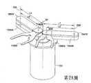
第2A圖顯示出根據所揭示實施例之一態樣的基板輸送裝置。Figure 2A shows a substrate transfer device according to one aspect of the disclosed embodiment.
第2B圖至第2J圖顯示出根據所揭示實施例之一態樣的基板輸送裝置。Figures 2B to 2J show a substrate transfer device according to one aspect of the disclosed embodiment.
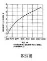
第2K圖及第2L圖是曲線圖,顯示出根據所揭示實施例之態樣的末端作用器的旋轉。Figures 2K and 2L are graphs showing the rotation of the end effector according to the disclosed embodiments.
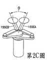
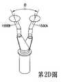
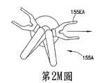
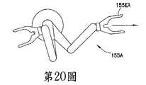
第2M圖至第2O圖顯示出根據所揭示實施例之一態樣的末端作用器的旋轉。Figures 2M through 20 show the rotation of the end effector according to one aspect of the disclosed embodiment.
第2P圖及第2Q圖顯示出根據所揭示實施例之態樣的末端作用器。Figures 2P and 2Q show the end effector according to the aspect of the disclosed embodiment.
第3圖、第3A圖、及第3B圖示意地顯示出根據所揭示 實施例之態樣的一驅動段及一基板輸送裝置的手臂。Figures 3, 3A, and 3B schematically show a driving section and an arm of a substrate conveying device according to the aspect of the disclosed embodiment.
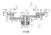
第3C圖至第3H顯示出圖根據所揭示實施例之一態樣的基板輸送裝置的一驅動段。FIGS. 3C to 3H show a driving section of the substrate transport apparatus according to one aspect of the disclosed embodiment.
第4A圖至第4H圖顯示出第2圖中根據一範例性實施例的基板輸送裝置的一範例件作業。FIGS. 4A to 4H show an example device operation of the substrate transfer apparatus in FIG. 2 according to an exemplary embodiment.
第4I圖顯示出根據所揭示實施例之一態樣的輸送腔室的側視圖。Figure 4I shows a side view of a delivery chamber according to one aspect of the disclosed embodiment.
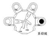
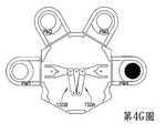
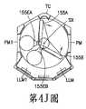
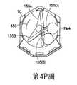
第4J圖至第4P圖顯示出根據所揭示實施例之態樣的輸送裝置的範例性作業。4J to 4P show exemplary operations of the conveying device according to the aspect of the disclosed embodiment.
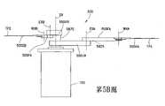
第5A圖及第5B圖顯示出根據所揭示實施例之一態樣的基板輸送裝置。FIGS. 5A and 5B show a substrate transfer device according to one aspect of the disclosed embodiment.
第6圖顯示出根據所揭示實施例之一態樣的基板輸送裝置的驅動段。FIG. 6 shows the driving section of the substrate transport device according to one aspect of the disclosed embodiment.
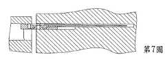
第7圖示意地顯示出根據一範例性實施例的範例性傳輸手臂延伸進入一處理模組。FIG. 7 schematically shows an exemplary transmission arm extending into a processing module according to an exemplary embodiment.
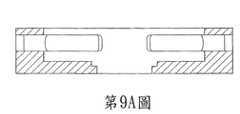
第8圖至第10圖是根據範例性實施例的傳輸腔室的示意圖。8 to 10 are schematic diagrams of the transmission chamber according to an exemplary embodiment.
第11圖顯示出根據所揭示實施例之一態樣的感應器系統。FIG. 11 shows an aspect of the sensor system according to the disclosed embodiment.
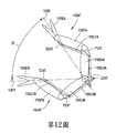
第12圖顯示出根據所揭示實施例之一態樣的基板輸送裝置。FIG. 12 shows a substrate transfer device according to one aspect of the disclosed embodiment.
第13圖是根據所揭示實施例之一態樣的基板處理系統的示意圖。FIG. 13 is a schematic diagram of a substrate processing system according to one aspect of the disclosed embodiment.
第14圖是第13圖中根據所揭示實施例之一態樣的基板 輸送裝置的示意圖。Fig. 14 is a schematic diagram of a substrate transport apparatus according to one aspect of the disclosed embodiment in Fig. 13;
第14A圖及第14B圖是第13圖中根據所揭示實施例之一態樣的基板輸送裝置的示意圖。FIGS. 14A and 14B are schematic diagrams of the substrate transport apparatus according to one aspect of the disclosed embodiment in FIG. 13.
第14C圖及第14D圖是根據所揭示實施例之態樣的基板輸送裝置驅動系統的示意圖。14C and 14D are schematic diagrams of the driving system of the substrate transport device according to the aspect of the disclosed embodiments.
第15A圖及第15B圖顯示出第13圖中根據所揭示實施例之一態樣的基板輸送裝置的手臂伸出及縮回路徑。FIGS. 15A and 15B show the extending and retracting paths of the arms of the substrate conveying device according to one aspect of the disclosed embodiment in FIG. 13.
第16A圖至第16G圖是根據所揭示實施例之一態樣的基板輸送裝置的部份的示意圖。16A to 16G are schematic diagrams of portions of a substrate transport apparatus according to one aspect of the disclosed embodiments.
第17A圖至第17C圖是根據所揭示實施例之一態樣的基板輸送裝置的部份的示意圖。FIGS. 17A to 17C are schematic diagrams of a portion of a substrate transport apparatus according to one aspect of the disclosed embodiment.
第18圖是根據所揭示實施例之一態樣的基板處理系統的示意圖。FIG. 18 is a schematic diagram of a substrate processing system according to one aspect of the disclosed embodiment.
第19A圖至第19E圖是根據所揭示實施例之一態樣的基板輸送裝置的示意圖。FIGS. 19A to 19E are schematic diagrams of a substrate transport apparatus according to one aspect of the disclosed embodiments.
第1圖顯示出一結合所揭示實施例之特點的基板處理裝置100的透視圖,並且顯示一基板215。雖然所揭示的實施例將會配合圖式來說明,但應瞭解到,該所揭示的實施例可以具有許多不同的形式。此外,任何適當尺寸、形狀、或型式的元件或材料均可使用。Figure 1 shows a perspective view of a
就本文中所描述的範例性實施例的目的而言,基板215可以是例如一半導體晶圓,例如200mm、300mm、 450mm或任何其他所需直徑的基板、任何其他型式適合由基板處理裝置100處理的基板、空白基板,或例如某些尺寸或特定質量之類等性質近似於基板的物體。基板處理裝置100是一種代表性的基板處理工具,其係顯示成具有一般成批處理之工具的架構。在其他的實施例中,該基板裝置可以是任何所需的型式,例如分類器、儲放器、度量工具等等。在本實施例中,裝置100基本上具有一氛圍段105,例如形成一迷你環境,以及一鄰接的氛圍隔離或密封(例如與外界氛圍隔離而密封)段(例如氛圍密封段)110,其可以例如設置成為一真空腔室。在其他的實施例中,氛圍密封段110可以保持住一惰性氣體(例如N2)或任何其他隔離開的氛圍。For the purpose of the exemplary embodiments described herein, the
在該範例性實施例的一態樣中,氛圍段105通常具有一個或多個基板固持卡匣115,以及一氛圍機器手臂120。氛圍機器手臂120可以是任何適當的機器手臂。就舉例而言,該氛圍機器手臂可以大致上類似於下文中會說明的輸送機器手臂130、530。氛圍機器手臂120可用以將基板輸送至氛圍段105內部的任何位置。例如,氛圍機器手臂120可將基板在基板固持卡匣115、負載鎖135、以及負載鎖140之間輸送。氛圍機器手臂120也可以將基板215送至及送出位在氛圍段105內的對準器162。In one aspect of this exemplary embodiment, the
氛圍密封段110可具有一個或多個處理模組PM1-PM6(在本文中將稱為處理模組125),以及一真空機器手臂130。處理模組125可以是任何的型式,例如材料積放、蝕 刻、烘烤、拋光、離子植入清潔等等。如可以理解的,每一處理模組125相對於所需之參考座標系,例如機器手臂參考座標系,的位置可記錄於控制器170內。在一範例性實施例中,基板處理裝置100內可有一個或多個處理模組對基板所進行的處理作業不同於其他處理模組所進行的處理作業。每一處理模組125相關的作業亦可記錄在控制器170。在其他的實施例中,處理模組可以進行相同的處理作業。氛圍密封段110亦可有一個或多個中間腔室,稱為負載鎖135、140。第1圖中所示的實施例設有二個負載鎖,但在其他的態樣中,氛圍密封段110可設有任何適當數量的負載鎖。負載鎖135及140的作用是如同界面一般,可讓基板通過氛圍段105與氛圍密封段110之間而不會破壞密封在氛圍密封段110內的任何真空或其他氛圍的完整性。根據該範例性實施例的一態樣,處理模組及/或負載鎖可以設置在共用的基板輸送平面上例如基板進入及離開該模組的傳輸路徑可以共平面)。The
基板處理裝置100通常包含一控制器170,用以控制基板處理裝置100的作業。控制器170具有一處理器173及一記憶體178。記憶體178可包含能施行基板處理裝置100之作業的電腦可讀取碼,以及其在本文中所描述的組件。例如,記憶體178可進一步包含處理參數,例如該裝置之處理模組及其他部位或段105、110之作業站的溫度及/或壓力、要處理的基板215的暫時資訊、以及基板的度量資訊。在所揭示之實施例的一態樣中,控制器170可具有群 集式架構,例如西元2005年7月11日提出申請之名稱為“Scalable Motion Control System”的美國專利申請案第11/178,615號中所描述者,該案的全部內容藉此參照併入本文。在其他的態樣中,控制器可具有任何適當的控制架構。The
參閱第2圖,在所揭示之實施例的一態樣中,輸送機器手臂130(其實質上是類似於氛圍機器手臂120)可包含一驅動段150及一個或多個手臂155A、155B。手臂155A、155B可附著至一驅動段150,該驅動段具有例如三軸或四軸驅動系統,將於下文中說明。手臂155A、155B,其在圖式中以例示方式顯示為三連桿SCARA(水平關節型機器手臂)手臂,可以同軸方式耦接至驅動段150,且可互相垂直堆疊於頂端上,以進行獨立的Theta(θ)運動(使用例如四軸驅動)或耦合式Theta運動(使用例如三軸驅動),該耦合式Theta運動是以機器手臂手臂做為一單元繞著肩軸線SX的旋轉,而實質上沒有伸出或縮回。每一手臂是由一對馬達驅動,並具有任何適當數量的驅動滑輪配置。在一態樣中,每一手臂的肩滑輪、肘滑輪、及腕滑輪間的直徑比值,就非限制性例示目的而言,可以是1:1:2的比值或2:1:2的比值。在伸出使用例如該1:1:2比值的手臂時,該對馬達中的每一馬達是大致上轉動相同及相反方向。在伸出使用例如2:1:2比值的手臂時,肩滑輪是大致上保持固定(例如大致上不轉動),而耦接上臂的馬達則轉動來伸出該手臂。Theta運動是透過讓馬達以大致上相同 的速度沿著相同的方向轉動來控制。當末端作用器如本文中所述是位在相同平面上時,每一手臂互相相對間的Theta運動會受到限制,但是如果手臂們是一起移動的話,則該臂在Theta軸上可以無限地移動。如可以理解的,當末端作用器並未位在相同平面上時,如下文所述,在每一手臂均是與其他手臂獨立驅動時,每一手臂均可在Theta軸上無限地移動,例如使用四軸驅動時。Referring to FIG. 2, in one aspect of the disclosed embodiment, the transport robot arm 130 (which is substantially similar to the atmospheric robot arm 120) may include a
應注意到,各手臂155A、155B的上臂155UA、155UB及前臂155FA、155FB在長度上可以大致上相等或是不相等。例如,上臂155UA、155UB可以比前臂155FA、155FB長或是相反過來。不同長度手臂的例子可參見西元2005年7月11日提出申請之名稱為“Unequal Link Scara Arm”的美國專利申請案第11/179,762號,該案的全部內容藉此參照併入本文。It should be noted that the upper arms 155UA, 155UB and the forearms 155FA, 155FB of each
以一非限制性的例子來說,參見第2圖(亦參見第4A圖),就大致上相等長度的手臂段而言,肩軸線SX與每一肘軸線EXA、EXB間的距離L1是大致上等於每一肘軸線EXA、EXB與相關腕軸線WXA、WXB間的距離L2。舉例來說,就不等長度的手臂段而言(參見第2A圖),肩軸線SX與每一肘軸線EXA、EXB間的距離L1可以大於或小於每一肘軸線EXA、EXB與各自之腕軸線WXA、WXB間的距離L2’(在第2A圖中距離L2’比較大)。可以理解的,當前臂段的長度大於相關上臂段長度時,腕軸線WXA、WXB可縮回的範圍會大於前臂及上臂具有大致上相同長度的情 形。例如,當末端作用器155EA、155EB是如本文中所述大致上位在相同平面上時,擺動半徑會受到基板直徑及腕部的限制,而不是例如手臂的肘部。將擺動半徑減至最小則手臂縮回的位置會是最小,因此在該機器手臂縮回位置時,晶圓中心會儘可能地靠近於機器手臂旋轉中心SX。讓例如前臂長度L2、L2’大於上臂的長度L1會讓每一大致上共平面的腕部能相對於具有大致上相同前臂及上臂長度的手臂更進一步地縮回。As a non-limiting example, see Figure 2 (also see Figure 4A), for an arm segment of substantially equal length, the distance L1 between the shoulder axis SX and each elbow axis EXA, EXB is approximately Up is equal to the distance L2 between each elbow axis EXA, EXB and the associated wrist axis WXA, WXB. For example, with regard to arm sections of unequal length (see FIG. 2A), the distance L1 between the shoulder axis SX and each elbow axis EXA, EXB may be greater or less than each elbow axis EXA, EXB and the respective wrist The distance L2' between the axes WXA and WXB (the distance L2' in Fig. 2A is relatively large). It can be understood that, when the length of the front arm segment is greater than the length of the relevant upper arm segment, the retractable range of the wrist axes WXA and WXB will be greater than that of the forearm and the upper arm having substantially the same length. For example, when the end effectors 155EA, 155EB are positioned substantially on the same plane as described herein, the swing radius is limited by the diameter of the substrate and the wrist, rather than the elbow of the arm, for example. When the swing radius is reduced to the minimum, the position where the arm is retracted will be the smallest. Therefore, when the robot arm is retracted, the wafer center will be as close as possible to the robot arm rotation center SX. For example, allowing the forearm lengths L2, L2' to be greater than the upper arm length L1 allows each substantially coplanar wrist to retract further relative to an arm having substantially the same length of the forearm and upper arm.
在所揭示之實施例的一態樣中(具有大致上等長或不等長的手臂連桿)可以讓基板中心實施自縮回位置至位在徑向位置上之工作站(例如相對於機器手臂肩軸線SX位在徑向位置上)的徑向路徑。應注意到基板沿著該徑向路徑旋轉的路可經由通過例如肘滑輪383、389(第3A圖)與各自之腕滑輪384、399(第3A圖)間的適當“齒輪”比而減低至最小。透過使用適當的滑輪比,基板旋轉在末端作用器路徑中止處的工作站可實質上消除掉。以不等長的上臂及前臂連桿舉例來說,並參閱第2K圖,其中顯示出例如2:1的肘/腕滑輪比時,末端作用器繞著基板中心旋轉的量(例如晶圓旋轉)。亦參閱第2L圖,其中顯示出例如1.7:1的肘/腕滑輪比時,末端作用器繞著基板中心旋轉的量。第2M圖至第2O圖顯示出手臂155A使用1.7:1的肘/腕比在完全縮回位置及完全伸出位置之間延伸,使得晶圓旋轉最大為例如2.5度。應注意到前述的滑輪直徑比值僅是舉例而已,應瞭解到該滑輪可以具有任何適當的直徑比 值。亦應注意到透過大致上類似於前面所述的方式,基板在延伸過程中的旋轉可相對於大致上具有相等長度之上臂及前臂減低至最小。In one aspect of the disclosed embodiment (with arm links of approximately equal or unequal length), the center of the substrate can be self-retracted to a workstation in a radial position (e.g., relative to the robot arm) The shoulder axis SX is in the radial position). It should be noted that the path of rotation of the substrate along this radial path can be reduced to a suitable "gear" ratio between, for example, elbow pulleys 383, 389 (Figure 3A) and respective wrist pulleys 384, 399 (Figure 3A) The smallest. By using an appropriate pulley ratio, the work station where the substrate rotates at the end of the end effector path can be substantially eliminated. Taking the unequal length of the upper arm and forearm links as an example, and referring to Figure 2K, which shows the amount of rotation of the end effector around the center of the substrate (for example, wafer rotation) at an elbow/wrist pulley ratio of, for example, 2:1 ). Also refer to Figure 2L, which shows the amount of rotation of the end effector about the center of the base plate at an elbow/wrist pulley ratio of, for example, 1.7:1. Figures 2M through 2O show that
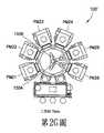
末端作用器可以任何適當方式建構,以固持住一個或多個基板215。例如,末端作用器155EA、155EB是顯示成具有單一板片來固持住單一片基板,但應瞭解到末端作用器可以具有多片板片,用以固持住多片基板。舉例來說,末端作用器155EH(第2P圖)可具有任何適當數量的基板固持板片BH1、BH2,水平排成一列,以邊靠邊的方式固持多片基板,或是末端作用器155EV(第2Q圖)可具有任何適當數量的基板固持板片BV1、BV2以堆疊方式垂直配置,以上下疊置方式固持住多片基板。在一例中,末端作用器155EA、155EB可以是邊緣抓持、真空抓持、主動抓持、或被動抓持式末端作用器。在該範例性實施例的一態樣中,末端作用器可耦接至上臂155UA、155UB及前臂155FA、155FB的各末端上,以使得末端作用器具有預定的角度關係。例如,參閱第2B圖至第2F圖,末端作用器之間的角度θ可以是任何適當的角度。在一態樣中,末端作用器155EA、155EB間的角度θ可以大致上等於群集式設備100’上徑向配置之處理模組,例如處理模組PM25、PM26,間的角度θ’。可以理解的,至少相對於當手臂是位可取用相鄰處理模組的位置時,當二手臂155A、155B均縮回(第2C圖及第2E圖)、當二手臂155A、155B均伸出(第2D圖)、以及當一手臂155B縮收而另一手臂155A 伸出(第2B圖)時,手臂155A、155B係可建構成能讓末端作用器155EA、155EB間的角度θ大致上維持住。可以理解的,當每一手臂均獨立繞著肩軸線SX轉動時,末端作用器的角度會符合於末端作用器伸入其內之各非相鄰處理模組(例如該非相鄰處理模組是由其他處理模組隔開的)的相關角度。第2G圖至第2J圖顯示出具有末端作用器155EA、155EB之手臂155A、155B的伸出,該末端作用器具有預定的角度θ,是大致上等於處理設備100’之處理模組PM21-PM26間的角度θ’。第2G圖顯示出二手臂155A、155B均縮回。第2H圖顯示出二手臂155A、155B分別伸入至處理模組PM26、PM25內。第2I圖顯示出手臂155B伸入至處理模組PM25內,而手臂155A縮回。第2J圖顯示出手臂155A伸入至處理模組PM26內而手臂155B縮回。The end effector may be constructed in any suitable manner to hold one or
驅動段150可接收來自例如控制器17的命令,並且因應之而進行手臂155A、155B的直接徑向運動、環周運動、升高運動、複合運動、以及其他的運動。手臂155A、155B可以任何適當方式裝設於驅動段150上。每一手臂155A、155B可包含以肩關節軸線SX可旋轉地裝設於驅動段上的上臂段155UA、155UB、以肘軸線EXA、EXB可旋轉地裝設於上臂段155UA、155UB上的前臂段155FA、155FB、以及以腕軸線WXA、WXB可旋轉地裝設於前臂段155FA、155FB上的末端作用器155EA、155EB。The
在所揭示之實施例的一態樣中,輸送機器手臂130可裝設於氛圍密封段110的中心腔室175內(參見第1圖)。 控制器170可作動來循環開口180、185並協調輸送機器手臂130的作動,以在處理模組125、負載鎖135、以及負載鎖140之間輸送基板。應瞭解到,雖然輸送機器手臂120、130是顯示並描述為具有SCARA型式機械臂,但這些輸送機器手臂可以包含任何適當的手臂架構,例如活節臂機器手臂、蛙腿式裝置、或雙對稱傳輸裝置。In one aspect of the disclosed embodiment, the
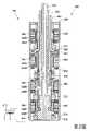
現在參閱第3圖,其中顯示出根據所揭示實施例之一態樣的一範例性驅動段150。在一態樣中,該驅動裝置可具有同軸驅動配置,而在其他的態樣中,該驅動段則可具有任何適當的驅動配置。適當的驅動段配置的例子可參見美國專利第6485250號、第5720590號、第5899658號、及第5813823號,其全部內容藉此參照併入本文。其他適當的驅動系統配置的例子則包括西元2008年6月27日提出申請而名稱為“Robot Drive with Magnetic Spindle Bearing”的美國專利申請案第12/163,996號中所描述者,該案的內容係全部併入本文內,以做為參考。在此例中,驅動段150包含一殼體310,以供至少部份地包覆一個四同軸驅動軸桿總成300,其具有四驅動軸桿301-304,以及四馬達342、344、346、348(例如一個四自由度馬達)。在該實施例的其他的態樣中,該驅動段150可以具有任何適當數量的驅動軸桿及馬達,例如二或三個同軸馬達或四個以上的同軸馬達,以及相關的驅動軸桿。第一馬達342包含一定子342S及一連接至外側軸桿304的轉子342R。第二馬達344包含一定子344S及一連接至軸桿303的轉子344R。 第三馬達346包含一定子346S及一連接至軸桿302的轉子346R。第四馬達348包含一定子348S及一連接至第四或內側軸桿301的轉子348R。該四個定子342S、344S、346S、348S是固定地附著至殼體310,上而位在殼體內的不同高度或位置處。每一定子342S、344S、346S、348S原則上包含一電磁線圈。每一轉子342R、344R、346R、348R原則上包含有永久磁鐵,但也可以包含不具有永久磁鐵的磁感應轉子。當輸送機器手臂130被應用於一密封環境內時,其係例如就非限制性舉例說明而言為一真空環境,可在轉子342R、344R、346R、348R及定子342S、344S、346S、348S之間設置套筒362,以使得該同軸驅動軸桿總成300是位在密封環境內,而定子則位在該密封環境外側。應認知到,如果輸送機器手臂130只是要使用在氛圍環境中的話,例如在基板處理裝置100的氛圍段105內(第1圖),則並不一定要設置套筒362。Referring now to FIG. 3, an
第四或內側軸桿301自底側或第四定子348S延伸出,並包含大致上對齊於定子348S的轉子348R。軸桿302自第三定子346S延伸出,並包含大致上對齊於定子346S的轉子346R。軸桿303自第二定子344S延伸出,並包含大致上對齊於定子344S的轉子344R。軸桿304自頂側或第一定子342S延伸出,並包含大致上對齊於定子342S的轉子342R。多個軸承350-353圍繞著軸桿301-304及殼體310設置,以使得每一軸桿301-304能夠互相相對及相對於殼體310獨立轉動。應注意到,每一軸桿均可設置一位置感應 器371-374。位置感應器371-374可用以提供有關於各軸桿301-304互相相對及/或相對於殼體310之旋轉位置的信號至任何適當的控制器,例如控制器170。感應器371-374可以是任何適當的感應器,例如以非限制例示而言,可以是光學或感應式感應器。The fourth or
亦參閱第2圖、第3A圖、及第3B圖,如前所述,輸送機器手臂130包含二手臂155A、155B。在所揭示之實施例的一態樣中,手臂155A的上臂155UA是固定地附著至外側軸桿304上,而使得該上臂155UA能隨著該軸桿304在一旋轉中心軸線(例如肩軸線SX)轉動。一滑輪380固定地附著至軸桿303上。上臂155UA包含一桿381及一可轉動地裝設於桿381上的滑輪382。桿381是固定地裝設於上臂155UA的一內側表面上。第一組傳動構件390延伸於滑輪380與滑輪382之間。應認知到,任何適當型式的傳動構件均可用來耦接至滑輪380、382上,例如皮帶、條帶、或鏈條。亦應認知到,雖然圖中顯示出二個傳動構件耦接至滑輪380、382上,但任何適當數量的傳動構件均可用來耦接至滑輪380、382上(例如多於或少於二個)。一軸桿382S固定地耦接至滑輪382上,以使得軸桿382S能隨著該滑輪繞著肘軸線EXA旋轉。軸桿382S可以以任何適當方式可轉動地支撐於地桿381上。前臂155FA是固定地裝設在軸桿382S上,以使得前臂155FA能隨著軸桿382S繞肘軸線EXA旋轉。前臂155FA包含一滑輪383,係可轉動地支撐於桿381的頂部末端。前臂155FA亦包含一桿385及一可轉動地 裝設在桿385上的滑輪384。第二組的傳動構件391(大致上類似於傳動構件390)延伸並耦接於滑輪383、384之間。末端作用器155EA是固定地裝設在滑輪384上,以使得該滑輪384及末端作用器155EA可繞著腕軸線WXA旋轉。如可以理解的,上臂155UA及前臂155FA係由各自之軸桿304、303獨立地驅動(例如轉動),以使得手臂155A能獨立旋轉T1及延伸R1,而末端作用器155EA的旋轉則跟從之,因此在該手臂沿著R1伸出及縮回時,末端作用器的縱向軸線可保持對齊於伸出及縮回軸線R1。在該實施例的其他態樣中,驅動段150可包含額外馬達及驅動軸桿,以使得末端作用器155EA亦能繞著腕軸線WXA獨立地旋轉。Also refer to FIG. 2, FIG. 3A, and FIG. 3B. As described above, the
手臂155B的臂155UB是固定地附著至內側軸桿301上,以使得上臂155UB能隨著軸桿301在一旋轉中心軸線(例如肩軸線SX)上轉動。一滑輪386固定地附著至軸桿302。上臂155UB包含一桿388及一可轉動地裝設在桿388上的滑輪387。桿388是固定地裝設在上臂155UB的一內側表面上。第一組傳動構件392(大致上類似於傳動構件390)延伸於滑輪386與滑輪387之間。一軸桿387S固定地耦接至滑輪387上,以使得軸桿387S能隨著該滑輪繞著肘軸線EXB轉動。軸桿387S可以任何適當方式可轉動地支撐於桿388上。前臂155FB固定地裝設至軸桿387S上,以使得前臂155FB能隨著軸桿387S繞肘軸線EXB轉動。前臂155FB包含一滑輪389,係可轉動地支撐於桿388的頂側末端上。前臂155FB亦包含一桿398及一可轉動地裝設在桿 398上的滑輪399。第二組傳動構件393(大致上類似於傳動構件390)延伸並耦接於滑輪389、399之間。末端作用器155EB是固定地裝設至滑輪399上,以使得滑輪399及末端作用器155EB可繞著腕軸線WXB轉動。如可以理解的,上臂155UB及前臂155FB係由各自之軸桿302、301獨立地驅動(例如轉動),以使得手臂155B能獨立旋轉T2及延伸R2,而末端作用器155EB的旋轉則跟從之,因此在該手臂沿著R2伸出及縮回時,末端作用器的縱向軸線可保持對齊於伸出及縮回軸線R2。在其他的實施例中,驅動段150可包含額外馬達及驅動軸桿,以使得末端作用器155EB亦能繞著腕軸線WXB獨立地旋轉。The arm 155UB of the
在另一態樣中,參閱第12圖,末端作用器繞著各自之腕軸線WXA、WXB的旋轉係以任何適當的方式,例如透過連桿組155LFA、155LUA、155LFB、155LUB,在伸出及縮回的過程中跟從於一個或多個上臂及前臂(例如並非獨立地驅動)。例如,參閱手臂155A,末端作用器155EA、前臂155FA、及上臂155UA每一者均分別具有各自的延伸部或耦接部EEXT、FEXT、UEXT。延伸部EEXT、FEXT、UEXT被建構成能將連桿組155LFA、155LUA、155LFB、155LUB耦接於各自的末端作用器155EA、前臂155FA、及上臂155UA。在此例中,連桿組155LUA的第一末端是耦接至上臂155UA的延伸部UEXT,連桿組155LUA的第二末端是耦接至前臂155FA的延伸部FEXT,使得連桿組155LUA在手臂155A的伸出及縮回過程 會大致上平行於上臂155UA。連桿組155LFA的第一末端是耦接至前臂155FA的延伸部FEXT,而連桿組155LFA的第二末端則耦接至末端作用器155EA的延伸部EEXT,使得連桿組155LFA在手臂155A的伸出及縮回過程會大致上平行於前臂155FA。可以理解的,當上臂155UA及前臂155FA旋轉以進行伸出及縮回時,連桿組155LUA、155LFA會將末端作用器保持於一預定方位(其在此例中是沿著線1200)上。應注意到,手臂155B’包含延伸部或耦接部EEXT、FEXT、UEXT及連桿組155LFB、155LUB,其等係類似於手臂155A’的延伸部及連桿組,因此在伸出及縮回過程,末端作用器155EB會維持沿著線1201。應注意到,桿組155LFA、155LUA、155LFB、155LUB可以應用至本文內所描述之根據所揭示實施例態樣的任何機器手臂架構上。In another aspect, referring to FIG. 12, the rotation of the end effector around the respective wrist axis WXA, WXB is in any suitable manner, for example, through the linkage set 155LFA, 155LUA, 155LFB, 155LUB The retraction process follows one or more upper arms and forearms (for example, not independently driven). For example, referring to
再次參閱第1圖、第2圖、第3A圖、及第3B圖,在此例中,軸桿382S、387S的尺寸是適當地設定,以使得末端作用器155EA、155EB的輸送平面TP是共平面的。末端作用器155EA、155EB的該共平面輸送平面可以讓基板在手臂155A、155B實質上沒有任何Z或垂直移動的情形下送入及送出基板固持站,例如處理模組125、負載鎖135、140、以及卡匣115。因此,該手臂可以對圍繞著輸送腔室而位在不同位置及方位上的一個以上的模組或負載鎖進行大致上同時的傳輸。在其他的實施例中,驅動段150可包含一Z移動馬達,用以進行手臂的Z動作。可以理解的,Z 運動可以建構於由該機器手臂服務的處理模組及/或負載鎖內,以使得基板可被提離或放置至末端作用器上(例如傳輸進入及離開末端作用器)。Referring again to Figure 1, Figure 2, Figure 3A, and Figure 3B, in this example, the dimensions of the
亦參閱第3C圖至第3H圖,其中顯示出根據所揭示實施例之一態樣的另一驅動系統1300。在此,驅動系統1300包含一同軸式主軸配置1310,由一偏置馬達配置1301驅動。可以理解的,馬達配置1301可以是任何適當的馬達,包括針對每一驅動軸線的實體上分離開的馬達(例如該馬達是沿著垂直及/或水平方向互相分隔的)或該馬達可以大致上類似於第3圖中所描述的馬達配置。在此例中,馬達配置1301可以位在處理裝置100的氛圍區域或馬達殼體1300H內,而驅動軸桿1311-1314用來驅動機器手臂手臂段的部位則位在處理裝置100的一密封及/或受控環境內。該馬達配置內的每一馬達能以任何適當方式耦接至各自的驅動滑輪DP1、DP2、DP3、DP4,例如透過板帶、線纜、齒輪、或任何其他適當的傳動構件。可以理解的,驅動系統1300亦可包含一Z軸馬達,大致上類似於第3圖中所描述的Z軸馬達312。Also refer to FIGS. 3C to 3H, which show another
如在第3E圖至第3H圖中最清楚看到的,同軸式主軸配置1310包含四個驅動軸桿1311-1314。可以理解的,驅動系統1300並不僅限於四個驅動軸桿(例如四軸驅動),也可以具有多於或少於四個驅動軸桿(及相關的驅動馬達)。最外側驅動軸桿1311是耦接至驅動滑輪DP1。驅動軸桿1312耦接至驅動滑輪DP2。驅動軸桿1313耦接至驅動 滑輪DP3。最內側驅動軸桿1314則耦接至驅動滑輪DP4。可以理解的,驅動軸桿與也們各自之滑輪間的耦接是可使得當一滑輪被驅動時,相關的驅動軸桿也會隨著該滑輪被驅動。在此,驅動軸桿1311-1314是受到包含有軸承1320-1323的巢套式軸承配置的徑向及軸向支撐,但亦可以任何其他適合的方式來支撐。軸承1320的外軸承環1320A是以任何適當的扣件,例如螺栓或螺釘,固定附著至例如殼體1300H的固定突緣1300X上。軸承1320的內軸承環1320B是以任何適當的方式,例如利用螺栓或螺釘,固定滑輪DP1及驅動軸桿1311。軸承1321的外軸承環1321A亦固定至軸承1320的內軸承環1320B,以使得軸承1321依靠於軸承1320的內軸承環1320B。軸承1321的內軸承環1321B可以固定至滑輪DP2及驅動軸1312。軸承1322的外軸承環1322A也固定至軸承1321的內軸承環1321B,以使得軸承1322依靠於軸承1321的內軸承環1321B。軸承1322的內軸承環1322B可以固定至滑輪DP3及驅動軸桿1313。軸承1323的外軸承環1323A可以任何適當的方式固定至驅動軸桿1313的內部,例如透過壓配/摩擦配合及/或設置於驅動軸桿1313底部的帽蓋。軸承1323的內軸承環1323B支撐並以任何適當的方式固定地附著至驅動軸桿1314上。軸承1323的內軸承環1323B也固定至驅動滑輪DP4(直接或透過軸桿1314),使得該滑輪亦由軸承1323的內軸承環1323B支撐。As best seen in Figures 3E through 3H, the
如前所述,驅動系統1300的馬達殼體1300H可以設置 在處理設備100的氛圍段,而驅動軸桿1311-1314中用以驅動手臂段的部位則設置在處理設備100的一密封及/或受控氛圍部份。合適的密封部,例如密封部FS1-FS8,可設置於驅動軸桿1311-1314之間及在驅動軸桿1311與突緣1300X之間。雖然圖中顯示出在每一驅動軸桿1311-1314之間及在突緣1300X與驅動軸桿1311之間設有二個密封部,但應瞭解到在這些區域內可以設置多於或少於二個的密封部。密封部FS1-FS8可以是磁性流體密封部,或任何其他能夠將殼體1300H的氛圍與處理設備100的氛圍密封隔開的密封部。密封部FS1-FS8可以任何適當的方式固持在定位,例如透過卡合環、夾扣、或壓配/干涉配合。As mentioned above, the
驅動系統1300的驅動軸桿1311-1314可以類似於前面配合第3圖及第3A圖所說明的方式耦接至各自的手臂段。例如,亦參閱第3A圖,手臂155A的上臂155UA是固定地附著至外側軸桿1311上,以使得上臂155UA可隨著軸桿1311在一旋轉中心軸線(例如肩軸線SX)上轉動。一滑輪380固定地附著至軸桿1312。上臂155UA包含一桿381及一可轉動地裝設在桿381上的滑輪382。桿381是固定地裝設在上臂155UA的內側表面上。第一組傳動構件390延伸於滑輪380與滑輪382之間。應認知到,任何適當型式的傳動構件均可用來耦接滑輪380、382,例如皮帶、條帶、或鏈條。亦應理解到,雖然圖中顯示出是以二個傳動構件來耦接滑輪380、382,但任何適當數量的傳動構件均可用來耦接滑輪380、382(例如多於或少於二個)。一軸桿382S固 定地耦接至滑輪382上,以使得軸桿382S能隨著該滑輪繞肘軸線EXA旋轉。軸桿382S是以任何適當方式可轉動地支撐於桿381上。前臂155FA是固定地裝設在軸桿382S上,以使得前臂155FA能隨著軸桿382S繞著肘軸線EXA旋轉。前臂155FA包含一滑輪383,係可轉動地被支撐於桿381的頂側末端。前臂155FA亦包含一桿385及一可轉動地裝設在桿385上的滑輪384。第二組傳動構件391(大致上類似於傳動構件390)延伸並耦接於滑輪383、384之間。末端作用器155EA是固定地裝設於滑輪384上,以使得滑輪384及末端作用器155EA能繞著腕軸線WXA旋轉。可以理解的,上臂155UA及前臂155FA是由各自之軸桿1311、1312獨立驅動(例如轉動),以讓手臂155A獨立旋轉T1及延伸R1,而末端作用器155EA的旋轉則跟從之,因此在手臂沿著R1伸出及縮回時,末端作用器的縱向軸線會保持大致上對齊於伸出及縮回R1的軸線。在其他的實施例中,驅動段150可包含額外的馬達及驅動軸桿,以使得末端作用器155EA亦能獨立地繞著腕軸線WXA旋轉。The drive shafts 1311-1314 of the
手臂155B的上臂155UB是固定地附著至內側軸桿1314上,使得上臂155UB能隨著軸桿1314繞一旋轉中心軸線(例如肩軸線SX)上轉動。一滑輪386固定地附著至軸桿1313。上臂155UB包含一桿388及一可轉動地裝設在桿388上的滑輪387。桿388是固定地裝設在上臂155UB的內側表面上。第一組傳動構件392(大致上類似於傳動構件390)延伸於滑輪386與滑輪387之間。一軸桿387S固定地耦接至 滑輪387上,以使得軸桿387S能隨著該滑輪繞肘軸線EXB旋轉。軸桿387S是以任何適當方式可轉動地支撐於桿388上。前臂155FB是固定地裝設在軸桿387S上,以使得前臂155FB能隨著軸桿387S繞著肘軸線EXB旋轉。前臂155FB包含一滑輪389,係可轉動地被支撐於桿388的頂側末端。前臂155FB亦包含一桿398及一可轉動地裝設在桿398上的滑輪399。第二組傳動構件393(大致上類似於傳動構件390)延伸並耦接於輪389、399之間。末端作用器155EB是固定地裝設於滑輪399上,以使得滑輪399及末端作用器155EB能繞著腕軸線WXB旋轉。可以理解的,上臂155UB及前臂155FB是由各自之軸桿1313、1314獨立驅動(例如轉動),以讓獨立旋轉T2及延伸R2,而末端作用器155EB的旋轉則跟從之,因此在手臂沿著R2伸出及縮回時,末端作用器的縱向軸線會保持大致上對齊於伸出及縮回R2的軸線。可以理解的,驅動段150可包含額外的馬達及驅動軸桿,以使得末端作用器155EB亦能獨立地繞著腕軸線WXB旋轉。The upper arm 155UB of the
參閱第4A圖至第4I圖,針對使用例如四軸線驅動的輸送機器手臂130的作動手臂155A說明。應瞭解到,手臂155B的作動是大致上類似於下文針對手臂155A所做的說明。在此例中,輸送機器手臂130是顯示為位在一傳輸腔室400內。第4I圖顯示出傳輸腔室400的側視圖。應注意到,該傳輸腔室包含可密封孔洞或埠口400P,其係可以任何適當的方式密封,例如使用門閥(未顯示)。埠口400P 的高度H及寬度W可最小化,以使得具有基板於其上的末端作用器155EA、155EB能在最小餘隙下通過該埠口。傳輸腔室400可以大致上類似於前面所描述的中心腔室175。此傳輸腔室包含有開口或門閥180,以供處理模組125(PM1-PM4)附著至其上。如前所述,手臂155A、155B的傳輸平面TP(例如末端作用器,以及前臂及腕部)(第3A圖)是共平面,因此手臂155A、155B的末端作用器155EA、155EB無法在不將輸送機器手臂的二個手臂155A、155B均繞著肩軸線SX轉動的情形下進出相同的處理模組。可以理解的,每一手臂155A、155B均能夠進出所有附著至傳輸腔室400上的處理模組(以及負載鎖-未顯示)。例如,在適當地旋轉一個或多個手臂時,每一手臂均能進出相鄰的處理模組、交錯分隔開的處理模組、以及大約180度分隔開的處理模組。Referring to FIGS. 4A to 4I, the
如第4A圖中所可看到的,手臂155A、155B是設置成能讓末端作用器155EA、155EB對齊於相鄰的處理模組PM1、PM2。若要伸出手臂155A以使得末端作用器155EA能進入處理模組PM2內,則馬達342要將軸桿304相對於軸桿303旋轉,而軸桿303則是大致上保持固定不動。但是,軸桿303在伸出及縮回的過程中可以在整個活動手臂總成155A啟動或結束時稍微地轉動,以加速傳輸的過程。在軸桿303(及滑輪380)保持固定不動而上臂155UA移動的情形下,滑輪382會被傳動構件390轉動。這接著則會將前臂155FA繞著軸線EXA轉動。由於滑輪383是固定地結合至桿 381上,且由於桿381是固定地附著至前臂155FA上,因此滑輪384會被傳動構件391相對於前臂155FA轉動。滑輪380、382、384互相相對間的大小是設定成可以讓末端作用器155EA沿著出/縮回軸線R1徑向平直地移進移出,如4B圖中所可看到。可以理解的,手臂155B的伸出及縮回是大致上類似的方式進行,其中是以馬達348將軸桿301相對於軸桿302轉動。As can be seen in FIG. 4A, the
轉動手臂155A(T1旋轉)而使該手臂自處理模組PM2移動至處理模組PM3是透過馬達342及344二者的運轉而使軸桿304、303大致上同時沿著相同的方向以大致上相同的速度轉動而達成的,如第4C圖所示。一旦手臂155A到達的位置是可使末端作用器155EA對齊於處理模組PM3時,該手臂即可以大致上類似於前面所述的方式進行伸出及縮回,如第4E圖所示。同樣的,要旋轉手臂155A(T1旋轉)來使該手臂自處理模組PM3移動至處理模組PM4,馬達342及344二者要進行運轉來使軸桿304、303大致上同時沿著相同的方向以大致上相同的速度轉動,如第4F圖所示。一旦手臂155A到達的位置是可使末端作用器155EA對齊於處理模組PM4時,該手臂即可以大致上類似於前面所述的方式進行伸出及縮回,如第4H圖所示。可以理解的,手臂155A在例如順時鐘方向上的轉動,如第4A圖至第4H圖所示,是受限於一個末端作用器因為例如傳輸平面TP、前臂155FA、155FB、以及腕部是位在相同平面上而大致上分隔開180度的旋轉點上。如此,輸送手臂的輸送路徑 R1、R2是互相相對成一角度,其中該角度的範圍是自相鄰的基板固持位置至大約180度相隔開的基板固持位置。Rotating the
可以理解的,在末端作用器155EA、155EB設置在大致上相同的傳輸平面TP(第3A圖)上而位在某些圓周上時,末端作用器155EA、155EB是無法互相通過的(亦即一手臂會擋住另一手臂的旋轉)。如此,個別手臂155A、155B的Theta運動會受到限制,或者僅部份獨立,其中手臂155A、155B必須要如同單一單元一樣一起繞著肩軸線SX轉動(例如長過程的移動)至要進出的“未阻擋”工作站。在其他的態樣中,手臂155EA、155EB可以互相獨立地移動,而能進出分隔開高達180度的工作站而不會讓一手臂阻擋另一手臂之進出工作站(例如負載鎖、處理模組等等)。例如,參閱第4J圖至第4L圖,其中顯示出具有處理模組PM及負載鎖模組LLM的範例性傳輸腔室TC。應瞭解到,傳輸腔室可以具有任何架構,包含任何適當數量的處理模組及負載鎖模組。如第4J圖至第4L圖中所可看到的,每一手臂155A、155B均可在不干擾到其他的手臂155A、155B的情形下移動自己的末端作用器155EA、155EB(例如短程移動),以出入分隔開達約180度的工作站。手臂155A、155B任一者各自進行之超過約180度的轉動會使得一手臂155A、155B試圖通過另一手臂155A、155B,如第4M圖至第4O圖所示,這在末端作用器位在相同平面TP上時是不可能的。為能進出超過180度的工作站,二手臂155A、155B必須要像一個單元一樣以相同速 度同時繞著肩軸線SX轉動。控制器,例如控制器170(第1圖),可以建構成能辨識那些工作站可透過短程移動來進出,以及那些工作站可透過長程移動來進出。在機器手臂的作業過程中,控制器170是建構成“不阻擋”要透過短程進出移動來出入的工作站(例如透過發出適當的命令給馬達驅動器來旋轉手臂)。例如,參閱第4J圖及第4M圖,如果末端作用器155EA要從處理模組PM1移動至處理模組PM4,則控制器170是建構成可認知到單獨移動手臂155A而不移動手臂155B來將末端作用器155EA移至處理模組PM4會造成手臂155A、155B間的碰觸。因此,如果會碰觸,則控制器不會單獨移動手臂155A,而是以會將手臂155A、155B當做一個單元來移動,例如沿著第4P圖中所示的方向450,以便不阻擋住對於處理模組PM4的進出,使末端作用器155EA得以進出處理模組PM4。It can be understood that when the end effectors 155EA and 155EB are arranged on substantially the same transmission plane TP (Figure 3A) and are located on certain circumferences, the end effectors 155EA and 155EB cannot pass each other (that is, one The arm will block the rotation of the other arm). In this way, the Theta movement of
現在參閱第5A圖及第5B圖,其中顯示出另一種根據範例性實施例的輸送機器手臂530。除了另外說明以外,輸送機器手臂530可以大致上類似於前面所描述的輸送機器手臂130。在此例中,輸送機器手臂530包含一驅動段150,其係大致上類似於前面針對第3圖及第3C圖至第3H圖所描述之驅動段或任何其他適當的驅動系統。可以理解的,驅動段150可包含一Z軸驅動器312(第3圖)。Z軸驅動器31可以任何適當方式連接至例如該驅動器150的殼體310。Z軸驅動器312可建構成能沿著Z方向驅動殼體310,包含任何連接至其上的手臂555A、555B,以使得每一手 臂555A、555B的末端作用器555EA,555EB能移動至不同的傳輸平面。Referring now to FIGS. 5A and 5B, another
在此例中,輸送機器手臂530包含二傳輸手臂555A、555B。傳輸手臂555A可以大致上類似於前面所描述的傳輸手臂155A,因此相同的結構會具有相同的參考編號(例如上臂555UA、前臂555FA、及末端作用器555EA)。傳輸手臂555A可以大致上類似於前面所描述的方式連接至該驅動段的軸桿304、303(第3圖)。傳輸手臂555B亦可大致上類似於前面所描述的傳輸手臂155B,因此相同的結構會具有相同的參考編號(例如上臂555UB、前臂555FB、及末端作用器555EB)。傳輸手臂555B可以大致上類似於前面所描述的方式連接至該驅動段的軸桿302、301(第3圖)。但是,在此例中,軸桿582S、587S(其等對應於第3圖中的軸桿382S、387S)的大小是可使得手臂555B可無限地大致上旋轉360度,而不會受到中斷且與手臂355A的旋轉獨立,反之亦然。此外,手臂555FB的前臂555FB可裝設在上臂555UB的底側(但在第2圖中,前臂155FB是裝設在上臂155UB的上側-例如垂直相對的前臂),因此末端作用器555EB的傳輸平面TP2是與末端作用器555EA的傳輸平面TP1接近但非共平面,以將利用不同手臂555A、555B來傳輸基板所需的Z運動的量實質上減至最小。此種非共平面的配置可以讓每一手臂獨立作動,而手臂的伸出及縮回R1、R2可互相相對呈一角度,且可在單一基板固持位置快速地交換基板。應注意 到,傳輸平面TP1、TP2間的間距可以是能讓該二末端作用器555EA、555EB在實質上沒有或最小的末端作用器的Z運動下插入至一傳輸埠口,例如400P(第4I圖)。可以理解的,當機器手臂530無法沿著Z軸移動手臂555A、555B時,該埠口會具有比埠口400P之高度H稍大的高度,及/或在機器手臂530所服務的處理模組及/或負載鎖必須內建Z移動。In this example, the
如前所述,該手臂,例如手臂155A、155B(具有大致上共平面的末端作用器),可由一個三軸驅動系統驅動,使得每一手臂之上臂155UA、155UB的Theta運動連結在一起(例如該上臂可旋轉成能在該上臂之間保持一預定角度)。參閱第6圖,三軸驅動系統634原則上包含一驅動軸桿總成641及三個馬達642、644、646。驅動軸桿總成641具有三驅動軸桿650A、650B、650C。可以理解的,該驅動系統並不侷限於三個馬達及三驅動軸桿。第一馬達642包含一定子648A及一連接至中間軸桿650A的轉子660A。第二馬達644包含一定子648B及一連接至外側軸桿650B的轉子660B。第三馬達646包含一定子648C及連接至內側軸桿650C的轉子660C。這三個定子648A、648B、648C是固定不動地附著至該管或殼體652上著該管的不同高度或位置處。僅就例示之目的而言,第一定子648A是中間定子,第二定子648B是頂側定子,而第三定子648C則是底側定子。每一定子基本上包含一電磁線圈。該三個軸桿650A、650B、及650C是設置成同軸心的軸桿。該三個 轉子660A、660B、660C最好是由永久磁鐵構成,但也可包含一不具有永久磁鐵的磁感應轉子。在轉子660與定子648之間取好設置套筒662,以供讓機器手臂能夠在驅動軸桿總成641位在真空環境內而定子648位在該真空環境外部的情形下應用於一真空環境內。但是,如果機器手臂只是供應用氛圍環境內,則不一定要設置套筒662。As previously mentioned, the arms, such as
第三軸桿650C是內側軸桿,自底側定子648C延伸出。此內側軸桿具有第三轉子660C,對齊於底側定子648C。中間軸桿650A自中間定子648A向上延伸。此中間軸桿具有第一轉子660A,對齊於第一定子648A。外側軸桿650B自頂側定子648B向上延伸。此外側軸桿具有第二轉子660B,對齊於頂側定子648B。多個軸承圍繞著650A-650C及管652設置,以使得每一軸桿能互相相對及相對於管662獨立旋轉。每一軸桿650A-650C可設置一位置感應器664。位置感應器664是用來通知控制器170(第1圖)軸桿650A-650C互相相對及/或相對於管652的旋轉位置。任何適當感應器均可使用,例如光學式或感應式。The
在此,上臂155UA是耦接至外側軸桿650B上,以使得在外側軸桿轉動時,上臂155UA會隨之轉動。上臂155UB是耦接至內側軸桿350C上,以使得在內側軸桿轉動時,上臂155UB會隨之轉動。具有第一或上滑輪段370A及第二或下滑輪段670B的滑輪670耦接至中間軸桿350A上,以使得在中間軸桿轉動時,滑輪670(及滑輪段670A、670B)會隨之轉動。可以理解的,滑輪670可以是單件式,或者該 二滑輪段670A、670B以任何適當方式互相固定在一起並固定至軸桿650A上。滑輪段670A是透過傳動裝置392耦接至手臂155B的滑輪387,而滑輪段670B則是透過傳動裝置390耦接至手臂155A的滑輪382。Here, the upper arm 155UA is coupled to the
該三個馬達642、644、646係可獨立地移動,以獨立地移動該二手臂155A、155B伸出及縮回。應注意到,該二手臂155A、155可以同時一起伸出、每次個別伸出一手臂、或一手臂伸出而另一手臂縮回。手臂155A、155B可移動而伸出及縮回該二末端作用器155EA、155EB,以供拾取及放置基板,而驅動器634則可將整個活動手臂總成(亦即二手臂155A、155B)做為一單元來一起繞著肩軸線SX旋轉,以將手臂155A、155B相對於處理模組、負載鎖及/或該手臂所處之處理設備的任何其他結構部重新定向。The three
要伸出及縮回手臂155A,馬達644會啟動而將外側軸桿650B相對於中間軸桿650A轉動。最好,中間軸桿650A在手臂155A伸出及縮回時是保持固定不動。但是,滑輪670在延伸或縮回的過程中可以在整個活動手臂總成啟動或結束時稍微地轉動,以加速傳輸的過程。在滑輪670保持固定不動而上臂155UA移動的情形下,滑輪382會被傳動構件390轉動。這接著則會將前臂155FA繞著肘軸線EXA轉動。由於滑輪383是固定地附著至桿381上,且由於該桿是固定地附著至上臂155UA上,因此滑輪384會被傳動構件391相對於前臂155FA轉動。應注意到,滑輪直徑比可 以是任何適當的比值,例如如同前面所描述者,以使得末端作用器(及其上的基板)能沿著徑向平直地移入及移出。To extend and retract the
要伸出及縮回手臂155B,馬達646會啟動而將內側軸桿650C相對於中間軸桿650A轉動。最好,中間軸桿650A在手臂155B伸出及縮回時是保持固定不動。但是,滑輪670在延伸或縮回的過程中可以在整個活動手臂總成啟動或結束時稍微地轉動,以加速傳輸的過程。在滑輪670保持固定不動而上臂155UB移動的情形下,滑輪387會被傳動構件392轉動。這接著則會將前臂155FB繞著肘軸線EXB轉動。由於滑輪389是固定地附著至桿388上,且由於桿388是固定地附著至上臂155UB上,因此滑輪399會被傳動構件393相對於前臂155FB轉動。應注意到,滑輪直徑比可以是任何適當的比值,例如如同前面所描述者,以使得末端作用器(及其上的基板)能沿著徑向平直地移入及移出。To extend and retract the
馬達642是配合於另外二個644、646使用,以將整個手臂總成繞著肩軸線SX轉動。馬達642係可旋轉來轉動中間軸桿650A,因之而轉動主滑輪670。馬達644、646可以和馬達642相同方向及速度移動,以使上臂155UA、155UB隨著滑輪670轉動。因此,傳動構件390、392不會轉動他們個別的滑輪382、387。因此,前臂155FA、155FB不會相對於他們個別的上臂155US、155UB轉動,而及滑輪384、399不會旋轉來轉動末端作用器155EA、155EB。可 以理解的,手臂155A、155B繞著肩軸線SX的旋轉是一種耦合旋轉(例如二手臂做為一單元一起旋轉,而上臂155UA、155UB間的角度則保持不變),而手臂的伸出及縮回則可個別或同時進行。亦可理解,一Z軸驅動器312(大致上類似於前面所描述者)可連接至驅動系統634,以沿著Z軸舉升及降下手臂155A、155B。The
可以理解的,本文中所描述的範例性輸送機器手臂130、530可供對基板進行依序處理,其中一個或多個處理模組125可對基板分別進行處理作業。例如,參閱第4A圖,一基板可利用手臂155A、155B放置於處理模組PM1內。在處理模組PM1內的處理完成後,手臂155A可自處理模組PM1內取出基板,並將其放置於處理模組PM2內。在與基板自處理模組PM1傳輸至處理模組PM2的同時,手臂155B可將另一基板自負載鎖135傳輸至處理模組PM1。此種配置可提供大致上連續的基板流,自例如負載鎖135通過處理模組PM1-PM4至負載鎖140。It can be understood that the exemplary
第7圖示意地顯示出輸送機器手臂130、530的手臂的範例性延伸進入至一處理模組內。應瞭解到,第7圖中所顯示的尺寸僅是例約略的例示,該尺寸可以大於或小於圖中所示者。在其他的實施例中,手臂可延伸進入位在任何適當水平距離及任何適當垂直位置的處理模組內。FIG. 7 schematically shows an exemplary extension of the arms transporting the
第8圖及第10圖是一傳輸腔室的範例頂視示意圖,例如傳輸腔室400。第9A圖及第9B圖是傳輸腔室400的示意側視圖,其中傳輸腔室的內部高度在輸送機器手臂包含一 Z驅動器時會加高。應瞭解到,第8圖至第10圖中所顯示的尺寸僅是例約略的例示,該尺寸可以大於或小於圖中所示者。應瞭解到傳輸腔室可具有任何適當的架構。8 and 10 are schematic top views of an example of a transmission chamber, such as the
參閱第11圖,本文中所描述的機器手臂可建構成,能配合控制器而在基板放置於一處理模組或工作站內時,來自動地將基板設置於中心。例如可將一個或多個感應器1002、1003設置於例如鄰近供一傳輸腔室與處理站1001之間的埠口旁邊。當機器手臂1030將攜帶一基板的末端作用器1030E伸出通過該埠口時,感應器1002、1003會偵測到該基板的一個或多個前緣及尾緣,並將對應於偵測到該基板之一個或多個前緣及尾緣的偵測信號輸送至控制器。控制器170可以任何適當方式使用該偵測信號來決定該基板相對於例如末端作用器1030E位置的位置。控制器170被建構成可在X及Y方向中的一者或多者上施用一偏置量XO、YO,以將基板置放在處理站1001預定的位置上。偏置量XO、YO可由控制器根據處理用組件(例如直接或間接與基板互動的組件)的熱膨脹量來計算,以使得該偏置量係為能夠補償該組件之熱成長的穩態偏置量。在範例實施例中,一個以上之處理模組及/或負載鎖(參見例如第1圖)的進出埠口可以具有類似的感應器配置。機器手臂1030可以類似於前面所描述的機器手臂。可以理解的,此機器手臂可以將二機器手臂末端作用器上的基板做大致上同時的自動多基板定心作業。Referring to FIG. 11, the robot arm described in this article can be constructed to automatically set the substrate at the center when the substrate is placed in a processing module or workstation with the controller. For example, one or
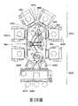
現在參閱第13圖,其中顯示出一基板處理裝置2000。 基板處理裝置2000可以是大致上類似於第1圖中的基板處理裝置100。例如,基板處理裝置2000基本具有一氛圍段2005,例如形成一迷你環境,以及一鄰接的氛圍隔離或密封(例如與外界氛圍密封)段(例如氛圍密封段)2010,其可以例如設置成為一真空腔室。在其他的實施例中,氛圍密封段110可以保持住一惰性氣體(例如N2)或任何其他隔離開的氛圍。該氛圍段可包含負載埠口2015、機器手臂2020,並且透過負載鎖2035、2040而耦接至氛圍密封段2010。氛圍密封段2010的型式可以是群集式設備,具有處理模組2025沿著徑向而圍繞著一中心腔室2075設置,其中每一處理模組均是互相相對呈一角度θ。中心腔室2075可包含有可將基板在負載鎖2035、2040之間傳輸的傳輸裝置2030及處理模組2025。在一態樣中,該傳輸裝置可大致上類似於西元2002年9月17日發證的美國專利第6,450,755號中所描述者,該案件的全部內容藉此參照併入本文。Referring now to FIG. 13, a
亦參閱第14圖,傳輸裝置2030可包含二個scara手臂2055A、2055B,大致上類似於前面所描述的手臂155A、155B,以及一動段。該傳輸裝置2030的驅動段可以是一個三軸同軸式驅動系統,大致上類似於前面配合第6圖所描述的三軸驅動系統634。在另一態樣中,傳輸裝置2030的驅動系統可以是大致上類似於前面配合第3C圖至第3H圖所描述之三軸同軸式驅動系統(具有例如驅動軸桿1314,或軸桿1311-1314中任一者,以及自該驅動取出之各自的滑輪/馬達組件)。一Z軸驅動器可耦接至該同軸式驅動 軸桿配置,以提供沿著Z方向的移動,以供以大致上類似於前面所描述的方式舉升及/或降低該手臂總成。Referring also to FIG. 14, the
每一手臂包含一上臂2055UA、2055UB、繞著肘軸線EXA、EXB裝設至上臂上的的一前臂2055FA、2055FB、以及繞著腕軸線WXA、WXB裝設至前臂2055FA、2055FB上的至少一末端作用器2055EA、2055EB。應注意到,在一態樣中,末端作用器2055EA、2055EB可以位在相同的傳輸平面TP上,以減少該手臂總成的Z運動量。在其他的態樣中,末端作用器可以位在不同的傳輸平面上。在此例中,手臂2055A、2055B繞著各自的肩軸線SX1、SX2裝設並被支撐於一基座構件2050上。例如,手臂2055A是繞著肩軸線SX1裝設至基座構件2050上,而手臂2055B則是繞著肩軸線SX2裝設至基座構件上。基座構件2050可具有任何適當的形狀及/或架構,並且及應注意到圖式中所顯示的三角形形狀其本質僅是例示之用而已。手臂2055A、2055B的末端作用器2055EA、2055EB可安排成能讓末端作用器2055EA、2055EB間互相相對呈一角度θ,以使得末端作用器2055EA、2055EB能以大致上類似於前面針對手臂155A、155B所描述的方式對齊於呈角度設置的處理模組2025中相鄰者。Each arm includes an upper arm 2055UA, 2055UB, a forearm 2055FA, 2055FB mounted on the upper arm around the elbow axis EXA, EXB, and at least one end mounted on the forearm 2055FA, 2055FB around the wrist axis WXA, WXB Actors 2055EA, 2055EB. It should be noted that in one aspect, the end effectors 2055EA and 2055EB may be located on the same transmission plane TP to reduce the amount of Z movement of the arm assembly. In other aspects, the end effector can be located on different transmission planes. In this example, the
基座構件2050可繞著驅動軸線TX(例如同軸驅動軸桿總成的轉動軸線)耦接至驅動段的一第一驅動軸D1(例如外側驅動軸桿),以使得在驅動軸桿D1旋轉時,基座構件2050會隨之旋轉。如第13圖中所可看到的,每一肩軸線 SX1、SX2可相對於驅動軸線TX設置,以使得該肩軸線是沿著各末端作用器2055EA、2055EB之伸出及縮回1501、1502的直線設置。一第一驅動滑輪DP1’耦接至驅動段的一第三驅動軸桿D3(例如內側驅動軸桿),使得在驅動軸桿D3旋轉時,滑輪DP1’會隨之旋轉。一第一肩滑輪SP1是裝設在繞著軸線SX1的軸上,其中第一肩滑輪SP1是以任何適當的方式耦接至第一驅動滑輪DP1,例如透過皮帶、條帶、齒輪、或任何其他適當的傳動裝置。肩滑輪SP1可以任何適當方式耦接至手臂2055A上,以供使該手臂沿著路徑1501伸出及縮回。在此例中,前臂2055FA及末端作用器2055EA的旋轉是以已知的方式透過任何適當的傳動系統2070A跟從於上臂2055UA的旋轉(例如利用2:1:1:2肩-肘-末端作用器滑輪比或任何其他適當的滑輪比),使得手臂2055A可僅使用單一驅動軸線來伸出及縮回,而腕軸線WXA及末端作用器2055EA在伸出及縮回的過程中則維持對齊於路徑1501(以類似於顯示在第15A圖及第15B圖而下文中將配合手臂2055B說明的方式)。應認知到,在其他的態樣中,可以在驅動段中設置另外的驅動軸桿/馬達,以使得手臂2055A的上臂、前臂、以及末端作用器中的二個或多個可以被個別地驅動。The
一第二驅動滑輪DP2’耦接至驅動段的第二驅動軸桿D2(例如中間驅動軸桿),以使得在驅動軸桿D2旋轉時,驅動滑輪DP2’會隨之旋轉。一第二肩滑輪是裝設在繞著軸線SX2的軸上,其中第二肩滑輪SP2是以任何適當的 方式耦接至第二驅動滑輪DP2,例如透過皮帶、條帶、齒輪、或任何其他適當的傳動裝置。肩滑輪SP2可以任何適當方式耦接至手臂2055B上,以供使該手臂沿著路徑1502伸出及縮回。在此例中,前臂2055FB及末端作用器2055EB的旋轉是以已知的方式透過任何適當的傳動系統2070B跟從於上臂2055UB的旋轉(例如利用2:1:1:2肩-肘-末端作用器滑輪比或任何其他適當的滑輪比),使得手臂2055B可僅使用單一驅動軸線來伸出及縮回,而腕軸線WXB及末端作用器2055EB在伸出及縮回的過程中則維持對齊於路徑1502,如第15A圖及第15B圖所示。應認知到,在其他的態樣中,可以在驅動段中設置另外的驅動軸桿/馬達,以使得手臂2055B的上臂、前臂、以及末端作用器中的二個或多個可以被個別地驅動。A second drive pulley DP2' is coupled to the second drive shaft D2 (e.g., intermediate drive shaft) of the drive section, so that when the drive shaft D2 rotates, the drive pulley DP2' will rotate accordingly. A second shoulder pulley is mounted on the axis around the axis SX2, wherein the second shoulder pulley SP2 is coupled to the second drive pulley DP2 in any suitable manner, such as through a belt, strap, gear, or any other Appropriate transmission. The shoulder pulley SP2 may be coupled to the
應注意到,第一及第二驅動滑輪DP1’、DP2’與相關肩滑輪SP1、SP2間的比值可以是1:1的比值。但是,在其他的實施例中,任何適當的比值均可應用於驅動滑輪與相關的肩滑輪之間。It should be noted that the ratio between the first and second drive pulleys DP1', DP2' and the associated shoulder pulleys SP1, SP2 may be a 1:1 ratio. However, in other embodiments, any suitable ratio may be applied between the drive pulley and the associated shoulder pulley.
參閱第14A圖至第14D圖,在所揭示之實施例的另一態樣中中,傳輸裝置2030可由一二軸同軸式驅動系統2099驅動,使得手臂2055A、2055B的伸出及縮回耦合在一起。應注意到,該二軸同軸式驅動系統可以大致上類似於配合第3圖、第3C圖至第3H圖、及第6圖所描述者,但僅有二驅動軸桿D1、D2及相關的馬達。例如,在第14C圖中顯示出一例示性二軸驅動系統(大致上類似於第3圖及第6 圖中所示的驅動系統),其具有第一及第二驅動軸桿D1、D2,分別由馬達1403、1404驅動,其中每一馬達包含一定子1403S、1404S及轉子1403R、1404R。另舉一例來說,另一範例性的二軸驅動系統(大致上類似於第3C圖至第3H圖中所示的驅動系統)顯示於第14D圖內,其具有第一及第二驅動軸桿1311(D1)、1312(D2)由各自之馬達(未顯示)透過滑輪DP1、DP2驅動。驅動軸桿中的第一個D1可大致上類似於前面所描述的方式耦接至基座構件2050。驅動軸桿中的第二D2可耦接至驅動滑輪DP1、DP2,使得在第二驅動軸桿D2旋轉時,驅動滑輪DP1、DP2會隨著驅動軸桿D2旋轉。在此例中,該驅動滑輪DP1、DP2之一者可以任何適當方式耦接至相關的肩滑輪SP1、SP2上,以使得該驅動滑輪及該肩滑輪以相同方向轉動(例如同為順時鐘或同為逆時鐘)。該驅動滑輪DP1、DP2的另一者則耦接至相關的肩滑輪SP1、SP2,以使得該驅動滑輪及該肩滑輪以相反的方向轉動(例如一滑輪順時鐘方向轉動,而另一滑輪逆時鐘方向轉動)。在此例中,驅動滑輪DP2及肩滑輪SP2是以任何適當的方式耦接在一起,例如透過皮帶、條帶、齒輪、或任何其他適當的傳動裝置2060,以使得滑輪DP2、SP2能沿著相同方向轉動。驅動滑輪DP1可以任何適當的方式耦接至肩滑輪SP1,例如透過皮帶、條帶、齒輪、或任何其他適當的傳動裝置2062,以使得滑輪DP1、SP1能沿著相反方向轉動。就例示的目的而言,第14B圖中的滑輪DP1、SP1是顯示成由一 “數字8”型式的皮帶/條帶配置來耦接,以使得在軸桿D2旋轉時,滑輪SP1、SP2是沿著相反方向旋轉。可以理解的,透過此種二軸同軸式驅動配置及被驅動滑輪DP1、DP2及相關肩滑輪SP1、SP2間相關的傳動,手臂2055A、2055B可以大致上同時延伸(例如二手臂透過該“數字8”型式的皮帶/條帶配置或任何其他適當的反向旋轉驅動架構而大致上同時伸入及退出基板固持位置),或者一手臂2055A、2055B伸出而另一手臂2055A、2055B縮回。在其他的態樣中,驅動軸桿D2與肩滑輪SP1、SP2間的耦接部可以是一種失動(Lost Motion)耦接部,大致上類似於西元2008年5月8日提出申請而名為“Substrate Transport Apparatus with Multiple Movable Arms Utilizing a Mechanical Swtich Mechanism”的美國專利申請案第12/117,415號及西元2007年4月6日提出申請而名稱為“Substrrate Transport Apparatus with Multiple Independently Movable Articulated Arms”的美國專利申請案第11/697,390號中所描述者,該案件的全部內容藉此參照併入本文。Referring to FIGS. 14A to 14D, in another aspect of the disclosed embodiment, the
在所揭示之實施例的另一態樣中,基座構件2050’,大致上類似於前面配合第13圖至第14A圖所描述的基座構件2050,係可調整的,以使得末端作用器2055EA、2055EB及相關手臂2055A、2055B可相對於驅動軸線TX做可調整的旋轉,以將末端作用器2055EA、2055EB對齊於基板固持位置(例如處理模組2025及負載鎖2035、2040) 間的角度α。例如,參閱第16A圖,基座構件2050’具有二個大致上相對的基座段1672、1678被建構成可分別支撐各自的手臂2055A、2055B。該段1672、1678互相接合在一起,在本實施例中是沿著基座構件2050’的驅動軸線接合部1635接合在一起。該段1672、1678是可以互相鎖固在一起,以使得基座構件2050’可做為一個單元來繞著驅動軸線TX旋轉。該大致上相對的基座段1672、1678也可以釋放,以供將該大致上相對的基座段1672、1678互相相對重新定位,以調整該基座段1672、1678間的角度。在所揭示實施例的其他的態樣中,基座構件2050’可包含任何所需數量的段,或者可以是單件式,具有可鎖固撓性接合部,以供將該段內的不同部位互相相對做位置調整。基座構件段1672大致上具有一中空框架或盒體,能夠包覆住將手臂2055A連接至驅動段中相關驅動軸桿的任何適當傳動裝置(參見例如前述的第14圖及第14A圖)。在其他的態樣中,基座構件段1672被建構成可包覆用來驅動手臂2055A的馬達。基座構件段1678也是大致上具有一中空框架或盒體,能夠包覆住將手臂2055B連接至驅動段中相關驅動軸桿的任何適當傳動裝置(參見例如前述的第14圖及第14A圖)。在其他的態樣中,基座構件段1678被建構成可包覆用來驅動手臂2055B的馬達。In another aspect of the disclosed embodiment, the base member 2050', which is substantially similar to the
如第16A圖及第16B圖所示,在本實施例中,該相對的段1672、1678被建構成讓手臂安裝表面MS1、MS2位在相同平面上,以使得手臂2055A、2055B大致上相同(但 互為鏡像),且末端作用器具有大致上相同的傳輸平面TP(參見第14圖及第14A圖)。在其他的態樣中,手臂安裝表面MS1、MS2互相相對間可以具有任何所需的架構。基座構件2050’的該安裝或耦接段1672S可由基座構件段1672的框架1673所構成。在一態樣中,框架1673圍繞著驅動段1699的同軸式軸桿總成(其可大致上類似於前面配合第14圖至第14D圖所描述者)延伸,以形成相對手臂段1678的一支座表面1673S。該表面1673S,其在此態樣中是大致上位在與基座構件段1672上表面位在相同平面上,針對基座構件段1678之垂直及水平定位於基座構件段1672具有定位結構。該相對基座構件段1678具有一框架1610,其具有一配接配接段1610S,係大致上針對安裝段1672S做相配合建構的,以使得配接段1610S可以裝設在安裝段1672S上。該定位結構是形成在支座表面1673S上的扣件孔1681A。同樣的,相對基座構件段1678的配接段1610S的支座表面亦具有扣件孔1681B。如下文中將會描述的,形成在各支座表面上的扣件孔1681A、1681B是散佈並分隔開,以提供用以標定手臂段1672、1678互相相對之位置所需的分度位置。扣件1681F,例如帽螺釘、螺栓、定位銷、或其等的任何組合,可穿過基座構件段1678的孔1681B進入另一基座構件段1672的相對應孔1681A內,而將基座構件2050’的二個基座構件段1672、1678互相鎖固在一起。該扣件係足供運動過程中傳輸力矩,因此基座構件段1678,其如前所述並非直接裝設至旋轉驅動器的外側軸桿(例如D1、 1311)上,例如配合第14圖至第14D圖所描述者(或本文中所描述的任何其他驅動器),會在相對基座構件段1672由外側軸桿D1在基座構件2050’之驅動軸線接合部1635處繞著共用旋轉軸線TX轉動時,與該基座構件段1672一起轉動。在所揭示之實施例的其他態樣中,任何其他適當的致能結構,例如栓槽、鍵/鍵槽,均可用來在該相對的基座構件段間進行定位及力矩傳輸。As shown in FIGS. 16A and 16B, in this embodiment, the opposing
定位孔1681A、1681B是環繞周邊等距離分佈於基座構件段1672、1678的各框架1673、1610上。任何適當數量的孔均可用來提供基座構件段1672、1678之間所需的增量調整間距,將說明於後。基座構件段的安裝段1673S、1610S上的定位孔的數量,當其一段1673S、1610S僅包含有供機械負載用的最小量孔時,其配接段上則會具有額外的孔,以供進行所需的位置調整或分度之用。例如,如果是使用四個扣件1681F來做機械結合之用,則一安裝段1673S、1610S會具有四個安裝孔1681A、1681B,而另一安裝段則可具有八個或十個或任何所需數量的孔,以配合基座構件段之間的調整動作。配接表面1673S、1610S可包含另外的嚙合結構,例如互鎖或交叉式唇部或邊緣(未顯示),其可在鎖定用扣件1681F取下時,將基座構件段穩定的固持在一起。因此,基座構件段1672、1678可在扣件1681F拆除後保持自我支撐,以進行位置調整,下文中將會說明。該嚙合結構可設有適當的滑動表面(未顯示),以允許基座構件段在進行位置調整時進行滑動運動,而不 會在該滑動表面上產生顆粒物質。在一態樣中,基座構件段的安裝段1673S、1610S是顯示成設置在基座構件2050’的驅動軸線接合部1635。在所揭示之實施例的其他態樣中,基座構件段之間的可調整連接可以設置在基座構件2050’上的任何其他位置上。The positioning holes 1681A and 1681B are distributed on the
在所揭示之實施例的其他態樣中,基座構件段1672、1678間的角度α可以做動態的調整。例如,參閱第16C圖,驅動器1699’可具有三個驅動軸桿D1-D3,其中外側驅動軸桿耦接至基座構件段1672上,以使得在該外側驅動軸桿旋轉時,基座構件段1672會隨之旋轉。內側驅動軸桿D3耦接至基座構件段1678,以使得在該內側驅動軸桿D3旋轉時,基座構件段1678會隨之旋轉。中間驅動軸桿D2耦接至滑輪SP1、SP2,以供以前面所述的方式伸出及縮回手臂2055A、2055B。一控制器(未顯示)連接至該驅動器1699’,以供動態地調整基座構件段1672、1678間的角度α。例如,要調整基座構件段1672、1678間的角度α,驅動軸桿D1及D3可互相相對旋轉所需之量,以使得該角度α能被動態地調整至任何所需角度。應注意到,驅動軸桿D1及D3可一起旋轉(例如以相同旋轉速度沿相同旋轉方向),使得基座構件2050’可做為一單元來轉動,而不會改變基座構件段1672、1678間的角度α。In other aspects of the disclosed embodiment, the angle α between the
基座構件2050、2050’亦可僅讓手臂2055A、2055B之一者進行獨立的Z移動。現在參閱第16D圖,基座構件2050”是顯示成具有基座構件段1672、1678’。基座構件段 1678’大致上相同於前面所述的基座構件段1678,但在所揭示之實施例的此態樣中,基座構件段1678’包含一第一部位1678A及一第二部位1678B。第一部位1678A是以大致上類似於前面所述的方式可調整地連接至基座構件段1672上,以供進行該基座構件段之間的分度定位。第二部位1678B可以任何適當的方式可移動地耦接至第一部位1678A,以使得第二部位1678B能在箭號1666的方向上沿著Z軸相對於第一部位1678A移動,將於下文中說明。在所揭示之實施例的此態樣中,驅動段1699可包含任何適當的主舉升或Z軸驅動器1687,其被建構成可將基座構件2050”(及手臂2055A、2055B)當做一個單元沿著方向或箭號1666舉升。但是,在某些例子中,當二手臂均被伸出來傳輸基板時,其會需要調整該基板之一者的最終放下位置,以使得一手臂沿著Z軸移動,而另一手臂則固定在Z上。在此例中,基座構件段1672及手臂2055A是由主要Z驅動器沿著Z軸定位,而基座構件段1678及手臂2055B可由驅動段1699中任何適當的次要Z驅動器1686另外沿著Z軸定位。應瞭解到,雖然基座構件段1678’是顯示成可由該次要Z驅動器1686沿著Z軸調整,但在所揭示之實施例的其他態樣中,另一基座構件段1672或是該二基座構件段1672、1678’被建構成能以本文中針對基座構件段1678’所描述之方式沿著Z軸獨立移動。The
參閱第16E圖,在所揭示之實施例的另一態樣中,基座構件段可建構成讓基座構件段1672’之一能由驅動段直 接支撐,而基座構件段1678”之另一者由一舉升連桿1615支撐,而該舉升連桿則是由基座構件段1672’適當地支撐並伸出其外。可以理解的,基座構件段1672’可具有一孔洞1615A,可供該舉升連桿穿過之,其係具有適當的形狀,以供將基座構件連桿1672’、78”互相相對分度定位並讓基座構件連桿1678”進行獨立的Z運動。在一態樣中,舉升連桿1615被建構成可提供支撐並導引基座構件段1678”的移動。在其他的態樣中,任何適當的導引軸承(說明於後)可提供基座構件段1678”的導引移動,並維持各手臂末端作用器的高度,以傳輸基板。Referring to FIG. 16E, in another aspect of the disclosed embodiment, the base member section may be constructed such that one of the base member sections 1672' can be directly supported by the driving section, and the other of the
現在參閱第16F圖來說明用以讓基座構件段(及相關手臂)之一者進行獨立垂直移動的舉升連桿組。應注意到,雖然該連桿組的作動及架構將配合第16D圖來說明,但該連桿組的作動及架構是大致上相同於第16E圖中所示的架構。在一態樣中,次要Z驅動器1686可以任何適當的方式樞轉地裝設於驅動段1699或基座構件段1672內。一樞轉連桿1669係繞著樞轉點1669P1樞轉地裝設於基座構件部位1678A內。樞轉連桿1669的第一末端1669E1是以任何適當的方式連接至次要Z驅動器1686上,例如透過一連接構件1686M,以使得當次要Z驅動器1686被致動時,該樞轉連桿會繞著點1669P1樞轉。樞轉連桿1669的第二末端1669E2是以任何適當的方式可移動地耦接至基座構件部位1678B上,以使得第二末端1669E2繞著樞轉點1669P1的旋轉運動能被轉換成基座構件部位1678B沿著Z軸的線性運 動。第二基座構件部位1678B係例如至少部份地透過一線性軸承配置LB可移動地耦接至並由第一基座構件部位1678A支撐,該線性軸承配置被建構成可導引第二基座構件部位1678B沿著Z軸的移動。應注意到,在手臂2055B的旋轉驅動器是位在驅動器1699上時,用以驅動手臂2055B的滑輪SP2係可移動地耦接至手臂驅動軸桿SD上,以使得在第二基座構件部位1678B沿著Z軸移動時,滑輪SP2能沿著軸桿SD做縱向滑動,而仍保持可旋轉地耦接於軸桿SD上。應瞭解到,此用來手臂2055B的滑輪配置可具有任何允許第二基座構件部位1678B沿著Z軸m之適當架構。一伸縮囊BL可設置於基座構件部位1678A、1678B之間,並係被建構成能包覆住一個或多個樞轉連桿1669及線性軸承LB。Reference is now made to Figure 16F to illustrate the set of lifting links used to allow one of the base member segments (and related arms) to move independently and vertically. It should be noted that although the operation and structure of the link group will be described in conjunction with FIG. 16D, the operation and structure of the link group are substantially the same as the structure shown in FIG. 16E. In one aspect, the
參閱第16G圖,在所揭示之實施例的另一態樣中,單軸驅動馬達可設置在基座構件的每一接合部。例如,單驅動馬達DM1設置在驅動接合部1635,以供將基座構件做為一個單元繞著軸線TX轉動。可以理解的,在基座構件部位可互相相對做動態調整時,一雙軸驅動器可設置於接合部1635,以供將基座構件段1672、1678”以大致上類似於前面所述的方式互相相對而個別地轉動。另一單軸驅動馬達DM2可繞著軸線SX2設置於基座構件段1678”內,以供驅動軸桿SD而使手臂2055B伸出及縮回。再另一個單軸驅動馬達(未顯示)可繞著軸線SX1設置於基座構件段1672內,以進行手臂2055A的伸出及縮回。應瞭解到,該單軸 驅動器DM1、DM2可大致上類似於前面配合第3圖、第3E圖至第3H圖、第6圖、第14C圖、及第14D圖所描述的驅動器,但僅包含單驅動馬達。亦應瞭解到,任何適當的編碼器ENC均可用來決定手臂及基座構件各個部位的位置。再者,雖然該位在基座段之每一接合部上的單軸驅動器是配合第16G圖來說明的,但應瞭解到該單軸驅動架構亦可應用於所揭示之實施例的任何態樣中。Referring to FIG. 16G, in another aspect of the disclosed embodiment, a single-axis drive motor may be provided at each joint of the base member. For example, the single drive motor DM1 is provided at the drive joint 1635 for rotating the base member as a unit around the axis TX. It can be understood that when the base member parts can be dynamically adjusted relative to each other, a dual-axis drive can be provided at the
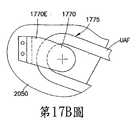
第17A圖至第17C圖顯示出一機器手臂的一部份,其中每一手臂1750、1751是由一遠方馬達或一位在手臂之肩部處的單軸馬達驅動。該遠方馬達及位在機器手臂之接合部處的馬達的例子係如前文所述。在所揭示之實施例的此態樣中,每一手臂包含一上臂UA、一連接至各自之上臂UA的前臂FA、以及一連接至各自之前臂FA的末端作用器(未顯示)。上臂UA是耦接至一肩驅動軸SD,用以將上臂UA繞著各自之肩旋轉軸線SX1、SX2轉動。在所揭示之實施例的此態樣中的手臂1750、1751是由一單軸驅動器1760以大致上類似於前面所述的方式驅動來伸出及縮回。手臂1750、1751的肩滑輪1770是固定在例如基座構件2050上,以使得該滑輪不會通過該肩接合部的中心。當每一上臂UA繞著各自軸線SX1、SX2轉動時,肩滑輪1770並不會轉動,使得手臂以跟從的方式配合該上臂的旋轉而伸出及縮回。在此,肩滑輪1770包含一延伸部1770E,其經由一孔洞1775伸出各上臂UA之殼體/框架UAF外。該延伸部1770E可以任何適當的方式固定至基座構件2050上,例如 透過任何適當的扣件、夾具等等。應注意到,上臂UA之殼體/框架UAF上的孔洞1775可具有適當的大小及形狀,以允許上臂UA旋轉來伸出及縮回手臂,而延伸部1770E則保持固定並相對於基座構件2050不動。應注意到,雖然該固定的肩滑輪1770是針對基座構件2050來說明的,但應瞭解到,第17A圖至第17C圖中的固定肩滑輪配置亦可應用至第16A圖至第16G圖或所揭示之實施例中任何其他適當態樣中的可調整的手臂段上。Figures 17A to 17C show a part of a robot arm, where each
參閱第18圖,第13圖至第17C圖中的基座構件/機器手臂手臂架構可裝設至一連桿組手臂1810上。例如,第18圖中所示的處理設備1800(其係大致上類似於前面所描述的設備100、2000)可包含一氛圍密封段2010及一氛圍段2005。氛圍段可包含負載埠口2015、機器手臂2020,並係透過負載鎖2035、2040耦接至氛圍密封段2010。氛圍密封段2010的型式可以是群集式設備,具有處理模組2025圍繞一中心腔室2075設置。中心腔室2075可包含一傳輸裝置1801,用以將基板在負載鎖2035、2040與處理模組2025間傳輸。該傳輸裝置1801包含在連桿組旋轉軸線LX處裝設至一驅動段1801D上的該連桿組手臂1810、繞著一基座構件旋轉軸線TX裝設至連桿組手臂1810上的一基座構件1850、以及繞著各自之肩軸線SX1、SX2裝設至基座構件1850上的手臂1860、1861。應注意到,構件1850可以大致上類似於前面所描述的基座構件2050或2050’。傳輸裝置1801可包含一驅動模組1801D,其係大致上類似於前面所 描述者,並設置在該連桿旋轉軸線LX處,用以旋轉驅動至少該連桿組手臂1810。在一態樣中,驅動模組1801D可包含一同軸式軸配置,其中一個軸驅動連桿組手臂1810的旋轉,一個軸驅動基座構件1850的旋轉,而一個或多個軸驅動手臂1860、1861之上臂UA的旋轉。該同軸式軸配置中的每一驅動軸桿可以任何適當的方式耦接至各自的連桿組手臂1810、基座構件1850、以及上臂UA上。例如,連桿組手臂1810可由其各自的驅動軸桿驅動,而基座構件1850及上臂UA則以大致上類似於前面所描述的方式透過適當的傳動裝置而耦接至他們各自的驅動軸桿。在另一態樣中,一單軸驅動器馬達可設置在旋轉軸線LX、TX、SX1、SX2的每一者處,以供以大致上類似於前面所描述的方式旋轉驅動傳輸裝置1801的相關部位。在此,連桿組手臂1810繞著軸線LX的旋轉可讓基座構件1850依所需定位而對齊於中心腔室2075的刻面角度。可以理解的,肩軸線SX1、SX2間的角度α係如前所述般可動態地調整,以使得手臂1860、186的末端作用器能對齊於該末端作用器要伸入其內的負載鎖2035、2040的處理模組2025。在其他的態樣中,可設置另外的馬達來個別地驅動每一手臂連桿(例如上臂、前臂、以及末端作用器係可個別地旋轉),以供進出處理模組2025、以及負載鎖2035、2040。Referring to FIG. 18, the base member/robot arm structure in FIGS. 13 to 17C can be mounted on a
參閱第19A圖至第19C圖,在所揭示之實施例的另一態樣中,一雙手臂輸送裝置1900被建構成具有雙SCARA手臂1901、1902及一驅動系統1910。驅動系統1910包含一串 接馬達配置,包含二個邊靠邊的馬達1920、1930。馬達1920、1930是同軸馬達(例如驅動軸桿是同軸設置),裝設於一共用的舉升框架1940。在一態樣中,馬達1920、1930是大致上類似於前面所描述的驅動系統。在另一態樣中馬達1920、1930是諧和式驅動器馬達。一Z驅動器1940D連接至舉升框架1940,用以在箭號1999的方向上沿著Z軸移動馬達1920、1930及機器手臂手臂1901、1902。一同軸式軸桿/滑輪配置被建構成可以大致上類似於前面配合第3C圖至第3H圖所描述的方式來支撐手臂總成。例如,馬達1920的一中空外側軸桿1920D1直接連接並支撐手臂1902的上臂1902UA。一內側軸桿192D2穿過該中空外側軸桿1902D1而耦接手臂1902的滑輪1902P1。適當的軸承可附著至外側軸桿1920D1上,並建構成能支撐內側軸桿1902D2及滑輪1901P2。滑輪1901P2是耦接至手臂1901的滑輪1901P3,並具有中空的中心或孔洞,可供外側軸桿1920D1穿過之。適當的軸承可附著至滑輪1901P2,並建構成能支撐直接耦接至手臂1901之上臂1901UA上的滑輪1901P1。滑輪1901P1亦可具有中空的中心或孔洞,可供滑輪1901P2穿過之來連接滑輪1901P3。滑輪1901P2可經由任何適當傳動裝置1960耦接至馬達1930的外側軸桿1930D1,例如皮帶、條帶、齒輪等等。滑輪1901P1可經由任何適當的傳動裝置1961耦接至馬達1930的內側軸桿1930D2,例如皮帶、條帶、齒輪等等。應注意到,馬達1930的內側軸桿及外側軸桿1903D1、1903D2可具有任何適當的滑輪裝設 至其上,以介接各自之傳動裝置1960、1961,並提供驅動軸桿1930D1、1930D2之旋轉與滑輪1901P1、1901P2之旋轉間的任何適當驅動比值。Referring to FIGS. 19A to 19C, in another aspect of the disclosed embodiment, a dual-
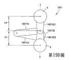
如第19A圖中所可看到的,手臂1901、1902二者均可繞共用軸線RX轉動。手臂1901、1902被建構成使該手臂之一者1902具有手臂連桿1902UA、1902FA,其等在長度上係短於另一手臂1901之手臂連桿1901UA、1901FA,以使得手臂1902能夠在手臂1901的肘擺動半徑內旋轉。這使得手臂1902能夠在縮回狀態下無限地繞著軸線RX旋轉,而不管手臂1901的位置為何。As can be seen in Figure 19A, both
手臂1901包含上臂1901UA、由一偏置量接合部1901J可轉動地耦接至上臂1901UA上的前臂1901FA,以及至少一末端作用器1901EE1、1901EE2。如前所述,上臂是由滑輪1901P1直接驅動。前臂1901FA是由滑輪1901P3驅動。滑輪1901P3是由任何適當的傳動裝置1963耦接至滑輪1901P4,而該滑輪則可轉動地耦接至前臂1901FA。該至少一末端作用器1901EE1、1901EE2係可做跟從動作,以使得在手臂1901伸出及縮回時,該至少一末端作用器1901EE1、1901EE2會保持對齊於一伸出/縮回軸線1998。在此例中,手臂1901包含二個相對的末端作用器1901EE1、1901EE2,其每一者被建構成可固持住一基板S。在一態樣中,在末端作用器做跟從動作時,手臂1901被建構成可在肩接合部1901SJ的任一側延伸出,以使得每一末端作用器1901EE1、1901EE2能將基板送入/送出基 板固持位置。在其他的態樣中,馬達1930上可加設一個或多個另外的驅動軸線及適當的傳動裝置,用以連接該驅動軸線至末端作用器上,以使得一個或多個末端作用器能獨立於上臂1901UA及前臂1901FA的旋轉而轉動。在其他的態樣中,手臂1901可包含任何適當數量的末端作用器。The
手臂1902包含上臂1902UA、可轉動地耦接至上臂1902UA上的前臂1902FA、以及末端作用器1902EE。如前所述,該上臂是由驅動軸桿1920D1直接驅動。前臂1902FA是由耦接至滑輪1902P1上的驅動軸桿1920D2驅動。滑輪1902P1可連接至滑輪1902P2,其係經由任何適當的傳動裝置1962可轉動地耦接至前臂1902FA上。在一態樣中,末端作用器1902EE係可做跟從動作,以使得在手臂1902伸出及縮回時,末端作用器1902EE會保持對齊於一伸出/縮回軸線1998。應注意到,雖然然圖式中僅顯示出一條伸出及縮回軸線1998,但應瞭解到,每一個別的可旋轉手臂1901、1902均可具有其自身的伸出及縮回軸線。在其他的態樣中,手臂1902可具有一個以上的末端作用器,其中該多個末端作用器可做跟從動作或獨立驅動。應注意到,在該多個末端作用器是個別驅動時,馬達1920可加設一個或多個另外的驅動軸線,以適當的傳動裝置,用以連接該驅動軸線至手臂1902的多個末端作用器上,以使得一個或多個末端作用器能獨立於上臂1902UA及前臂1902FA的旋轉而轉動。應注意到,雖然末端作用器1901EE1、1901EE2、1902EE是顯示為單一基板末端作用器,但在其 他的態樣中,末端作用器可建構成能以邊靠邊或上下疊置方式固持一個以上的基板(參見第2P圖、第2Q圖)。The
手臂1901的偏置量接合部1901J、上臂1901UA、及前臂1901FA可構成一個手臂1902的包容區域1990。例如,偏置量接合部1901J可具有足夠的長度或高度,以使得手臂1902的上臂1902UA、前臂1902FA、及末端作用器1902EE能套設於手臂1901的上臂1901UA與前臂1901FA之間。接合部中心至接合部中心的手臂長度或共用旋轉軸線RX與手臂1901之肩軸線SAX1間的距離L1亦可大於接合部中心至接合部中心的手臂長度或共用旋轉軸線RX與手臂1902之肩軸線SAX2間的距離L2,以使得手臂1902能夠在該包容區域1999內無限地自由轉動(至少在手臂1902處於縮回狀態下)而不會受到手臂1901的干涉。The offset
應注意到,末端作用器1901EE、1902EE1、1902EE2的長度可以是任何適當的長度,以使得二手臂1901、1902能夠到達每一處理模組、負載鎖、或其他由機器手臂1900服務的基板固持站。例如,作用器1902EE的長度L3可大於手臂1901的末端作用器1901EE1、1901EE2的長度L4,以補償較短長度的上臂1902UA及前臂1902FA。在其他的態樣中,末端作用器長度L3、L4可大致上相同,其中手臂1901、1902的旋轉中心RX是充份地靠近於基板固持站,以使得較長的手臂1901只能部份地延伸來將基板送至/送出該固持站。應注意到,在延伸進入基板固持站時,因為例如連桿長度或末端作用器長度上的差異之故,手臂1901 的手臂連桿1901FA、1901UA間的角度β是小於手臂1902之手臂連桿1902FA、1902UA間的角度μ(參見第19B圖)。一控制器1911可連接至輸送裝置1900上。該控制器可以大致上類似於前面所描述的控制器170。控制器1911可建構成能操控該輸送裝置,以使得當一手臂1901、1902輸送一基板至一基板固持站時,另一手臂可獨立地旋轉並對齊(未伸出手臂)於相同或不同的基板固持站,以預先進行或準備下一回的基板輸送。例如,參閱第1圖,如果傳輸裝置1900(第1圖中的輸送機器手臂130)要傳輸一基板至處理模組PM6,然後自負載鎖140拾取一基板,則手臂1901、1902中的第一個會伸入至處理模組PM6來輸送該基板,而手臂1901、1902中的第二個則獨立旋轉而使末端作用器對齊於負載鎖模組140,使得第二手臂1901、1902在第一手臂自處理模組PM6縮回後立即地伸入至負載鎖140內。It should be noted that the length of the end effectors 1901EE, 1902EE1, 1902EE2 may be any suitable length, so that the two
在所揭示之實施例的第一態樣中提供一基板處理裝置。該基板處理裝置包含一框架、一第一手臂耦接至該框架、及一第二手臂耦接至該框架。一驅動段耦接至該第一及第二手臂並被建構成能獨立延伸及旋轉該第一及第二手臂之每一者,其中該第一手臂的延伸軸線相對於該第二手臂的延伸軸線呈一角度。In the first aspect of the disclosed embodiment, a substrate processing apparatus is provided. The substrate processing apparatus includes a frame, a first arm coupled to the frame, and a second arm coupled to the frame. A driving section is coupled to the first and second arms and is constructed to independently extend and rotate each of the first and second arms, wherein the extension axis of the first arm is relative to the extension of the second arm The axis is at an angle.
根據所揭示之實施例的第一態樣,每一手臂包含一末端作用器,被建構成能固持住至少一基板,其中該末端作用器是位在一共用的傳輸平面上。According to the first aspect of the disclosed embodiment, each arm includes an end effector configured to hold at least one substrate, wherein the end effector is located on a common transmission plane.
根據所揭示之例示性實施例的第一態樣,每一手臂包含一末端作用器,被建構成能固持住至少一基板,其中該末端作用器是位在不同的傳輸平面上。According to the first aspect of the disclosed exemplary embodiment, each arm includes an end effector configured to hold at least one substrate, wherein the end effector is located on different transmission planes.
根據所揭示之例示性實施例的第一態樣,該驅動段包含一個四自由度驅動系統。According to the first aspect of the disclosed exemplary embodiment, the driving section includes a four-degree-of-freedom driving system.
根據所揭示之例示性實施例的第一態樣,該驅動段包含一同軸心式驅動軸桿配置。According to a first aspect of the disclosed exemplary embodiment, the drive section includes a coaxial drive shaft arrangement.
根據所揭示之實施例的第一態樣,該第一手臂包含沿一肩軸線連接至該驅動段的一上臂、沿一肘軸線連接至該上臂的一前臂、以及沿一腕軸線耦接至該前臂的一末端作用器。該第二手臂包含沿一肩軸線連接至該驅動段的一上臂、沿一肘軸線連接至該上臂的一前臂、以及沿一腕軸線耦接至該前臂的一末端作用器。該第一及第二手臂每一者的該肩軸線是一共用軸線。According to a first aspect of the disclosed embodiment, the first arm includes an upper arm connected to the driving section along a shoulder axis, a forearm connected to the upper arm along an elbow axis, and coupled to a wrist axis An end effector of the forearm. The second arm includes an upper arm connected to the driving section along a shoulder axis, a forearm connected to the upper arm along an elbow axis, and an end effector coupled to the forearm along a wrist axis. The shoulder axis of each of the first and second arms is a common axis.
根據所揭示之實施例的第一態樣,該前臂以一種相對的架構互相相對設置,使得該第一手臂的該前臂是位在一相關上臂的上表面上,而該第二手臂的該前臂則位在一相關上臂的底面上。According to the first aspect of the disclosed embodiment, the forearms are arranged opposite to each other in a relative structure, such that the forearm of the first arm is located on the upper surface of an associated upper arm, and the forearm of the second arm It is on the bottom surface of an associated upper arm.
根據所揭示之實施例的第一態樣,該驅動段包含一個三自由度驅動系統,連接至該第一及第二手臂,以使得在該手臂繞著一共用軸線轉動時,該第一手臂的一上臂與該第二手臂的一上臂間的角度大致上是固定的。According to a first aspect of the disclosed embodiment, the drive section includes a three-degree-of-freedom drive system connected to the first and second arms so that when the arm rotates about a common axis, the first arm The angle between the upper arm of and the upper arm of the second arm is substantially fixed.
根據所揭示之實施例的第一態樣,第一手臂以及第二手臂每一者包含一末端作用器,其中末端作用器係裝設至 他們各自的手臂上,以使得該末端作用器間的角度大致上相當於可由每一手臂進出之徑向相鄰基板固持站之間的角度。According to a first aspect of the disclosed embodiment, each of the first arm and the second arm includes an end effector, wherein the end effector is mounted on their respective arms so that the The angle is roughly equivalent to the angle between radially adjacent substrate holding stations that can be accessed by each arm.
根據所揭示之實施例的第一態樣,該基板輸送裝置包含一控制器及至少一感應器,該控制器被建構成可自該至少一感應器取得基板偵測信號,並施加一偏置量至該第一及第二手臂之一者的一末端作用器的位置上,其中該偏置量是根據至少該基板輸送裝置的熱膨脹量計算。According to a first aspect of the disclosed embodiment, the substrate transport device includes a controller and at least one sensor, the controller is constructed to obtain a substrate detection signal from the at least one sensor and apply a bias Measured to the position of an end effector of one of the first and second arms, wherein the offset is calculated based on at least the thermal expansion of the substrate transport device.
根據所揭示之實施例的一第二態樣,其提供一基板處理裝置。該基板處理裝置包含一驅動段、一第一手臂耦接至該驅動段、一第二手臂耦接至該驅動段,其中該第一及第二手臂每一者包含一末端作用器,且該末端作用器是設置在大致上相同的平面上。該處理裝置亦包含一控制器,連接至該驅動段,並係被建構成可控制該驅動段來繞著一肩軸線旋轉驅動該手臂,並伸出及縮回該手臂。該控制器係被建構成可個別地旋轉每一手臂,並可辨識該手臂的旋轉何時會造成該手臂間的碰觸及碰觸會發生在何處,該控制器係被建構成可將該手臂當做一個單元來繞著該肩軸線轉動。According to a second aspect of the disclosed embodiment, it provides a substrate processing apparatus. The substrate processing apparatus includes a driving section, a first arm coupled to the driving section, and a second arm coupled to the driving section, wherein each of the first and second arms includes an end effector, and the The end effectors are arranged on substantially the same plane. The processing device also includes a controller connected to the driving section, and is constructed to control the driving section to rotate and drive the arm around a shoulder axis, and extend and retract the arm. The controller is constructed to rotate each arm individually, and can recognize when the rotation of the arm will cause contact between the arms and where the contact will occur. The controller is constructed to rotate the arm Act as a unit to rotate around the shoulder axis.
根據所揭示之實施例的第二態樣,該驅動段是一個四自由度驅動器,具有四個同心的驅動軸桿。According to a second aspect of the disclosed embodiment, the drive section is a four-degree-of-freedom drive with four concentric drive shafts.
根據所揭示之實施例的第二態樣,該四個同心驅動軸桿受到巢套式軸承配置的徑向及軸向支撐,其中該軸承之一者的至少一部份是裝設在該軸承中另一者的一部份上。According to a second aspect of the disclosed embodiment, the four concentric drive shafts are supported radially and axially by a nested bearing arrangement, wherein at least part of one of the bearings is mounted on the bearing Part of the other.
根據所揭示之實施例的第二態樣,每一手臂包含一上臂連桿及一前臂連桿,其中該上臂連桿具有與該前臂連桿不同的長度。According to a second aspect of the disclosed embodiment, each arm includes an upper arm link and a forearm link, where the upper arm link has a different length than the forearm link.
根據所揭示之實施例的第二態樣,每一手臂包含一末端作用器,其係被建構成可支撐至少一基板。According to a second aspect of the disclosed embodiment, each arm includes an end effector that is constructed to support at least one substrate.
根據所揭示之實施例的一第三態樣,其提供一基板處理裝置。該基板處理裝置包含至少一輸送手臂及一驅動段。該驅動段包含一巢套式軸承配置及一同軸驅動軸桿總成,其中該巢套式軸承配置包含同心疊置的軸承,係被建構成可徑向及軸向支撐該驅動軸桿總成。According to a third aspect of the disclosed embodiment, it provides a substrate processing apparatus. The substrate processing device includes at least one conveying arm and a driving section. The drive section includes a nested bearing arrangement and a coaxial drive shaft assembly, wherein the nested bearing arrangement includes concentrically stacked bearings and is constructed to support the drive shaft assembly radially and axially .
根據所揭示之實施例的第三態樣,該軸承係被建構成能讓一軸承的至少一內軸承環耦接至另一軸承的一外軸承環。According to a third aspect of the disclosed embodiment, the bearing is constructed to allow at least one inner bearing ring of one bearing to be coupled to an outer bearing ring of another bearing.
根據所揭示之實施例的第三態樣,該驅動段是一個三自由度驅動系統。According to a third aspect of the disclosed embodiment, the driving section is a three-degree-of-freedom driving system.
根據所揭示之實施例的第三態樣,該驅動段是一個四自由度驅動段。According to a third aspect of the disclosed embodiment, the driving section is a four-degree-of-freedom driving section.
根據所揭示之實施例的第三態樣,其中該同心疊置軸承中的一最外側軸承的一外軸承環是耦接至該驅動系統的一殼體,並係被建構成可支撐該驅動軸總成及該同心疊置軸承中的其他軸承。According to a third aspect of the disclosed embodiment, an outer bearing ring of an outermost bearing in the concentric stacked bearings is coupled to a housing of the drive system and is constructed to support the drive The shaft assembly and other bearings in the concentric stacked bearing.
根據所揭示之實施例的第三態樣,磁性流體密封部設置於該驅動軸桿總成的該驅動軸桿之間,以將該驅動系統之一殼體內的氛圍密封而從其中設置著該第一和第二手臂 的氛圍隔離。According to a third aspect of the disclosed embodiment, a magnetic fluid seal is provided between the drive shafts of the drive shaft assembly to seal the atmosphere in one housing of the drive system from which the The atmosphere of the first and second arms is isolated.
根據所揭示之實施例的第三態樣,該至少一輸送手臂包含二輸送手臂,其每一者具有一末端作用器,其中該末端作用器設置於相同的平面上。According to a third aspect of the disclosed embodiment, the at least one conveying arm includes two conveying arms, each of which has an end effector, wherein the end effector is disposed on the same plane.
根據所揭示之實施例的第三態樣,該至少一輸送手臂包含二輸送手臂,其每一者具有一末端作用器,其中該末端作用器設置於不同的平面上。According to a third aspect of the disclosed embodiment, the at least one conveying arm includes two conveying arms, each of which has an end effector, wherein the end effector is disposed on different planes.
根據所揭示之實施例的一第四態樣,其提供一基板處理裝置。該基板處理裝置包含一驅動段;一大致上堅硬的基座構件,耦接至並被該驅動段繞著一第一旋轉軸線支撐;一第一輸送手臂,可轉動地裝設至並由該基座構件繞著一第二旋轉軸線支撐,該第一輸送手臂包含至少一末端作用器;一第二輸送手臂,可轉動地裝設至並由該基座構件繞著一第三輸送手臂支撐,該第二輸送手臂包含至少一末端作用器;其中該第一手臂的該至少一末端作用器及該第二手臂的該至少一末端作用器具有一共用的基板輸送平面,且該第一及第二輸送手臂裝設至該基座構件而使得該第一輸送手臂的延伸軸線相對於該第二輸送手臂的延伸軸線呈一角度。According to a fourth aspect of the disclosed embodiment, it provides a substrate processing apparatus. The substrate processing apparatus includes a driving section; a substantially rigid base member coupled to and supported by the driving section around a first axis of rotation; a first transport arm rotatably mounted to and supported by the The base member is supported around a second axis of rotation, the first conveyor arm includes at least one end effector; a second conveyor arm is rotatably mounted to and supported by the base member around a third conveyor arm , The second transport arm includes at least one end effector; wherein the at least one end effector of the first arm and the at least one end effector of the second arm have a common substrate transport plane, and the first and second The two conveying arms are mounted to the base member so that the extension axis of the first conveying arm is at an angle relative to the extension axis of the second conveying arm.
根據所揭示之實施例的第四態樣,該驅動段被建構成可將該基座構件及該第一及第二輸送手臂當做一單元來繞著該第一軸線旋轉,並且獨立地伸出及縮回該第一及第二輸送手臂之每一者。According to a fourth aspect of the disclosed embodiment, the driving section is constructed to rotate the base member and the first and second conveying arms as a unit around the first axis and extend independently And retract each of the first and second delivery arms.
根據所揭示之實施例的第四態樣,該驅動段被建構成 可將該基座構件及該第一及第二輸送手臂當做一單元來繞著該第一軸線旋轉,並且能同時伸出及縮回該第一及第二輸送手臂,以使得該第一輸送手臂的伸出及縮回耦合於該第二輸送手臂的伸出及縮回。According to a fourth aspect of the disclosed embodiment, the driving section is constructed to rotate the base member and the first and second conveying arms as a unit around the first axis and can simultaneously extend And retract the first and second conveying arms such that the extension and retraction of the first conveying arm are coupled to the extension and retraction of the second conveying arm.
根據所揭示之實施例的第四態樣,該驅動段是被建構成能沿著大致上平行於至少該第一旋轉軸線的方向來移動該基座構件及該第一及第二輸送手臂。According to a fourth aspect of the disclosed embodiment, the driving section is constructed to move the base member and the first and second conveying arms in a direction substantially parallel to at least the first axis of rotation.
根據所揭示之實施例的第四態樣,該基板處理裝置進一步包含基板固持站,其中該第一輸送手臂的延伸軸線與該第二輸送手臂的延伸軸線間的角度是大致上等於相鄰基板固持站間的角度。According to a fourth aspect of the disclosed embodiment, the substrate processing apparatus further includes a substrate holding station, wherein the angle between the extension axis of the first transfer arm and the extension axis of the second transfer arm is substantially equal to the adjacent substrate Hold the angle between the stations.
根據所揭示之實施例的第四態樣,該基座構件包含一第一基座連桿,具有第一及第二末端;以及一第二基座連桿,具有第一及第二末端;其中該第一基座連桿及該第二基座連桿的該第一末端藉由一可釋放耦接部繞著該第一旋轉軸線互相可釋放地耦接在一起,以構成該大致上堅硬的基座構件,使得該第一基座連桿及第二基座連桿在耦接在一起時,係可做為一單元繞著第一軸線旋轉,且該第一及第二基座連桿在釋放開時,其間的角度是可以調整,且其中該第一及第二輸送手臂之一者是可轉動地裝設在該第一基座連桿的該第二末端,而該第一及第二輸送手臂的另一者則是可轉動地裝設至該第二基座連桿的該第二末端。在一次態樣中,該驅動段包含至少一第一及第二驅動軸線,其包含該可釋放耦接部,其中該第一及第二驅動軸線在耦 接在一起時,可以沿著相同方向以大致上相同的速度被驅動,且在釋放開時,該第一及第二驅動軸線中至少一者係可獨立於該第一及第二驅動軸線中另一者被驅動。在另一次態樣中,該可釋放耦接部包含機械扣件。According to a fourth aspect of the disclosed embodiment, the base member includes a first base link with first and second ends; and a second base link with first and second ends; The first end of the first base link and the first end of the second base link are releasably coupled to each other around the first axis of rotation by a releasable coupling part to form the substantially A rigid base member, so that when the first base link and the second base link are coupled together, they can be used as a unit to rotate around the first axis, and the first and second bases When the connecting rod is released, the angle between it can be adjusted, and one of the first and second conveying arms is rotatably installed at the second end of the first base connecting rod, and the first The other of the first and second conveying arms is rotatably mounted to the second end of the second base link. In one aspect, the driving section includes at least a first and a second driving axis including the releasable coupling part, wherein the first and the second driving axis can be along the same direction when coupled together Driven at substantially the same speed, and when released, at least one of the first and second drive axes can be driven independently of the other of the first and second drive axes. In another aspect, the releasable coupling portion includes a mechanical fastener.
根據所揭示之實施例的第四態樣,該基板處理裝置進一步包含一延伸手臂,其中該延伸部手臂的一第一末端可轉動地耦接至該驅動段,而該基座構件則可轉動地耦接至該延伸手臂的一第二末端,並由其支撐。According to a fourth aspect of the disclosed embodiment, the substrate processing apparatus further includes an extension arm, wherein a first end of the extension arm is rotatably coupled to the driving section, and the base member is rotatable Is coupled to and supported by a second end of the extended arm.
根據所揭示之實施例的第四態樣,該驅動段包含一馬達,其係被建構成能以獨立於該第一及第二輸送手臂中另一者之移動的方式沿著大致上平行於第二及第三軸線中相關之一者的方向移動該第一及第二輸送手臂中之一者。在一次態樣中,該驅動段進一步包含一舉升馬達,其被建構成可將該基座構件及該第一及第二輸送手臂二者做為一單元沿著大致上平行於第二及第三軸線中相關之一者的方向來移動。According to a fourth aspect of the disclosed embodiment, the drive section includes a motor that is constructed to be substantially parallel to the movement of the other of the first and second conveying arms The direction of one of the second and third axes moves one of the first and second conveying arms. In one aspect, the driving section further includes a lift motor, which is constructed such that the base member and the first and second conveying arms can be taken as a unit along the direction parallel to the second and the first Move in the direction of the relevant one of the three axes.
根據所揭示之實施例的第四態樣,該驅動段包含單軸馬達,設置於該第一、第二、及第三軸線的每一者。According to a fourth aspect of the disclosed embodiment, the drive section includes a single-axis motor disposed on each of the first, second, and third axes.
根據所揭示之實施例的第四態樣,該第一及第二輸送手臂之每一者包含該第一及第二輸送手臂之每一者包含一上臂連桿,可轉動地裝設於該基座構件上,並連接至該驅動系統,以供轉動該上臂;一前臂連桿,可轉動地裝設於該上臂連桿上;以及該至少一末端作用器係可轉動地裝設於該前臂連桿,該至少一末端作用器透過一傳動系統跟從 於該上臂連桿的轉動,其中該傳動系統包含一滑輪,設置在該第二及第三軸線之相關一者上,且該滑輪係固定地耦接至該基座構件。According to a fourth aspect of the disclosed embodiment, each of the first and second conveyor arms includes each of the first and second conveyor arms includes an upper arm link that is rotatably mounted on the The base member is connected to the driving system for rotating the upper arm; a forearm link is rotatably mounted on the upper arm link; and the at least one end effector is rotatably mounted on the Forearm link, the at least one end effector follows the rotation of the upper arm link through a transmission system, wherein the transmission system includes a pulley, which is disposed on a related one of the second and third axes, and the pulley is Fixedly coupled to the base member.
根據所揭示之實施例的一第五態樣,其提供一基板處理裝置。該基板處理裝置包含一框架;一驅動段,連接至該框架,該驅動段具一旋轉驅動軸線;一第一手臂,包含連接至該驅動段以繞著該旋轉驅動軸線轉動的一上臂連桿、繞著一肘軸線可轉動地耦接至該上臂連桿的一前臂連桿、以及繞著一腕軸線可轉動地耦接至該前臂連桿的一末端作用器;以及一第二手臂,包含連接至該驅動段以繞著該旋轉驅動軸線轉動的一上臂連桿、繞著一肘軸線可轉動地耦接至該上臂連桿的一前臂連桿、以及繞著一腕軸線可轉動地耦接至該前臂連桿的一末端作用器;其中該第一手臂被建構成可讓該第二手臂在該第一手臂的該上臂及前臂間為一縮回狀態下以與該第一手臂之位置無關的方式繞著該旋轉驅動軸線轉動。According to a fifth aspect of the disclosed embodiment, it provides a substrate processing apparatus. The substrate processing apparatus includes a frame; a driving section connected to the frame, the driving section has a rotational drive axis; a first arm includes an upper arm link connected to the driving section to rotate about the rotational drive axis , A forearm link rotatably coupled to the upper arm link about an elbow axis, and an end effector rotatably coupled to the forearm link around a wrist axis; and a second arm, Includes an upper arm link connected to the drive section to rotate about the rotational drive axis, a forearm link rotatably coupled to the upper arm link about an elbow axis, and rotatably about a wrist axis An end effector coupled to the forearm link; wherein the first arm is constructed to allow the second arm to retract with the first arm in a retracted state between the upper arm and the forearm of the first arm It rotates around the rotation drive axis in a position-independent manner.
根據所揭示之實施例的第五態樣,該驅動段包含一同軸式軸配置,其被建構成將該第一及第二手臂連接至該驅動段。在第一次態樣中,該同軸式軸桿配置包含一內側軸桿、一外側軸桿,一第一中間軸桿、以及一第二中間軸桿;該內側軸桿及該第一中間軸桿驅動該第二手臂,而該第二中間軸桿及該外側軸桿驅動該第一手臂;以及該第一中間軸桿被建構成軸向支撐該第二中間軸桿,而該第二中間軸桿則建構成軸向支撐該外側軸桿。在第二次態樣中, 該驅動段進一步包含至少二個邊靠邊設置的馬達,耦接至該同軸式軸桿配置。在第三次態樣中,該至少個邊靠邊設置的馬達每一者包含一多自由度馬達。在第四次態樣中,該至少二個邊靠邊設置的馬達每一者為諧和式驅動器。According to a fifth aspect of the disclosed embodiment, the drive section includes a coaxial shaft configuration that is constructed to connect the first and second arms to the drive section. In the first aspect, the coaxial shaft arrangement includes an inner shaft, an outer shaft, a first intermediate shaft, and a second intermediate shaft; the inner shaft and the first intermediate shaft The rod drives the second arm, and the second intermediate shaft and the outer shaft drive the first arm; and the first intermediate shaft is constructed to axially support the second intermediate shaft, and the second intermediate The shaft is constructed to axially support the outer shaft. In the second aspect, the driving section further includes at least two side-by-side motors coupled to the coaxial shaft configuration. In the third aspect, each of the at least one side-by-side motor includes a multi-degree-of-freedom motor. In the fourth aspect, each of the at least two side-by-side motors is a harmonic drive.
根據所揭示之實施例的第五態樣,該基板處理裝置進一步包含有連接至該框架的基板固持位置及一控制器,該控制器被建構成可獨立旋轉該第一及第二手臂之一者,以將該第一及第二手臂之該一者的一末端作用器對齊於一基板固持站,而該第一及第二手臂的另一者則傳輸一基板至同一或不同的基板固持站,以預先進行後續的基板傳輸。According to a fifth aspect of the disclosed embodiment, the substrate processing apparatus further includes a substrate holding position connected to the frame and a controller configured to independently rotate one of the first and second arms In order to align an end effector of the one of the first and second arms to a substrate holding station, and the other of the first and second arms transmits a substrate to the same or different substrate holding Station to perform subsequent substrate transfer in advance.
應瞭解到,其次的說明僅是做為該實施例的示範而已。熟知此技術術之人士當可安排出多種不會脫離該實施例的變化及改良。因此,本實施例等係涵蓋所有落入下附申請專利範圍的該替代、修飾、及變化。It should be understood that the following description is only for demonstration of this embodiment. Those skilled in the art can arrange a variety of changes and improvements without departing from this embodiment. Therefore, this embodiment and the like cover all the substitutions, modifications, and changes that fall within the scope of the attached patent application.
100‧‧‧基板處理裝置100‧‧‧Substrate processing device
105‧‧‧氛圍段105‧‧‧Ambient Section
110‧‧‧氛圍密封段110‧‧‧ Atmosphere sealing section
115‧‧‧基板固持卡閘115‧‧‧Basic Card Holder
120‧‧‧氛圍機器手臂120‧‧‧Ambient Robot Arm
125‧‧‧處理模組125‧‧‧Processing module
130‧‧‧輸送機器手臂130‧‧‧Transport robot arm
135‧‧‧負載鎖135‧‧‧ load lock
140‧‧‧負載鎖140‧‧‧ load lock
162‧‧‧對準器162‧‧‧Aligner
170‧‧‧控制器170‧‧‧Controller
173‧‧‧處理器173‧‧‧ processor
175‧‧‧中心腔室175‧‧‧ Central chamber
178‧‧‧記憶體178‧‧‧ memory
180‧‧‧開口180‧‧‧ opening
185‧‧‧開口185‧‧‧ opening
215‧‧‧基板215‧‧‧ substrate
Claims (29)
Translated fromChineseApplications Claiming Priority (2)
| Application Number | Priority Date | Filing Date | Title |
|---|---|---|---|
| US201161451912P | 2011-03-11 | 2011-03-11 | |
| US61/451,912 | 2011-03-11 |
Publications (2)
| Publication Number | Publication Date |
|---|---|
| TW201811513A TW201811513A (en) | 2018-04-01 |
| TWI691388Btrue TWI691388B (en) | 2020-04-21 |
Family
ID=46796797
Family Applications (2)
| Application Number | Title | Priority Date | Filing Date |
|---|---|---|---|
| TW106131822ATWI691388B (en) | 2011-03-11 | 2012-03-12 | Substrate processing tool |
| TW101108322ATWI614831B (en) | 2011-03-11 | 2012-03-12 | Substrate processing tool |
Family Applications After (1)
| Application Number | Title | Priority Date | Filing Date |
|---|---|---|---|
| TW101108322ATWI614831B (en) | 2011-03-11 | 2012-03-12 | Substrate processing tool |
Country Status (6)
| Country | Link |
|---|---|
| US (7) | US8918203B2 (en) |
| JP (5) | JP6059156B2 (en) |
| KR (5) | KR102436038B1 (en) |
| CN (1) | CN103503127B (en) |
| TW (2) | TWI691388B (en) |
| WO (1) | WO2012125572A2 (en) |
Families Citing this family (79)
| Publication number | Priority date | Publication date | Assignee | Title |
|---|---|---|---|---|
| WO2012031635A1 (en)* | 2010-09-10 | 2012-03-15 | Abb Research Ltd. | Industrial robot |
| TWI691388B (en)* | 2011-03-11 | 2020-04-21 | 美商布魯克斯自動機械公司 | Substrate processing tool |
| KR20180128987A (en)* | 2011-09-16 | 2018-12-04 | 퍼시몬 테크놀로지스 코포레이션 | An apparatus for moving substrates |
| KR20130083857A (en)* | 2012-01-13 | 2013-07-23 | 노벨러스 시스템즈, 인코포레이티드 | Dual arm vacuum robot |
| US10363665B2 (en)* | 2012-07-10 | 2019-07-30 | Persimmon Technologies Corporation | Linear robot arm with multiple end effectors |
| JP5532110B2 (en)* | 2012-11-16 | 2014-06-25 | 株式会社安川電機 | Substrate transfer robot and substrate transfer method |
| US9190306B2 (en)* | 2012-11-30 | 2015-11-17 | Lam Research Corporation | Dual arm vacuum robot |
| US10224232B2 (en) | 2013-01-18 | 2019-03-05 | Persimmon Technologies Corporation | Robot having two arms with unequal link lengths |
| US9149936B2 (en) | 2013-01-18 | 2015-10-06 | Persimmon Technologies, Corp. | Robot having arm with unequal link lengths |
| WO2014143662A1 (en)* | 2013-03-15 | 2014-09-18 | Applied Materials, Inc | Substrate deposition systems, robot transfer apparatus, and methods for electronic device manufacturing |
| US9454158B2 (en) | 2013-03-15 | 2016-09-27 | Bhushan Somani | Real time diagnostics for flow controller systems and methods |
| US9842757B2 (en) | 2013-06-05 | 2017-12-12 | Persimmon Technologies Corporation | Robot and adaptive placement system and method |
| JP6229324B2 (en)* | 2013-06-14 | 2017-11-15 | セイコーエプソン株式会社 | ROBOT, ROBOT CONTROL DEVICE, AND ROBOT CONTROL METHOD |
| US10424498B2 (en)* | 2013-09-09 | 2019-09-24 | Persimmon Technologies Corporation | Substrate transport vacuum platform |
| SG2013069893A (en)* | 2013-09-13 | 2015-04-29 | Jcs Echigo Pte Ltd | Material handling system and method |
| JP2015076433A (en)* | 2013-10-07 | 2015-04-20 | 東京エレクトロン株式会社 | Substrate transfer method |
| US9761478B2 (en) | 2014-01-28 | 2017-09-12 | Brooks Automation, Inc. | Substrate transport apparatus |
| WO2015120369A1 (en) | 2014-02-10 | 2015-08-13 | Persimmon Technologies, Corp. | Robot having predetermined orientation |
| DE102014009892B4 (en)* | 2014-07-04 | 2018-05-30 | gomtec GmbH | Drive unit with magnetic interface |
| WO2016056119A1 (en)* | 2014-10-10 | 2016-04-14 | 川崎重工業株式会社 | Substrate conveyor robot and method for operating same |
| KR102000690B1 (en)* | 2014-12-26 | 2019-07-16 | 카와사키 주코교 카부시키 카이샤 | Articulated robot |
| KR101963334B1 (en)* | 2014-12-26 | 2019-03-28 | 카와사키 주코교 카부시키 카이샤 | Double-armed robot |
| EP3056320B1 (en)* | 2015-02-10 | 2018-12-05 | F. Hoffmann-La Roche AG | Robotic device and laboratory automation system comprising robotic device |
| CN107408526B (en) | 2015-03-12 | 2022-03-15 | 柿子技术公司 | Robot with driven end effector movement |
| US9866035B2 (en)* | 2015-03-27 | 2018-01-09 | Irobot Corporation | Rotatable coupling |
| JP6826044B2 (en)* | 2015-04-20 | 2021-02-03 | アプライド マテリアルズ インコーポレイテッドApplied Materials,Incorporated | Buffer chamber wafer heating mechanism and support robot |
| US10134623B2 (en) | 2015-07-13 | 2018-11-20 | Brooks Automation, Inc. | On the fly automatic wafer centering method and apparatus |
| WO2017041007A1 (en)* | 2015-09-04 | 2017-03-09 | Douglas Machine Inc. | Improved robotic article handling system & operations |
| CN106548970B (en)* | 2015-09-23 | 2019-10-11 | 北京北方华创微电子装备有限公司 | Lifting device and semiconductor processing equipment |
| US10124492B2 (en)* | 2015-10-22 | 2018-11-13 | Lam Research Corporation | Automated replacement of consumable parts using end effectors interfacing with plasma processing system |
| US9827677B1 (en) | 2016-05-16 | 2017-11-28 | X Development Llc | Robotic device with coordinated sweeping tool and shovel tool |
| US9827678B1 (en) | 2016-05-16 | 2017-11-28 | X Development Llc | Kinematic design for robotic arm |
| TWI724971B (en)* | 2016-06-28 | 2021-04-11 | 美商應用材料股份有限公司 | Dual robot including spaced upper arms and interleaved wrists and systems and methods including same |
| US11270904B2 (en)* | 2016-07-12 | 2022-03-08 | Brooks Automation Us, Llc | Substrate processing apparatus |
| JP6635888B2 (en)* | 2016-07-14 | 2020-01-29 | 東京エレクトロン株式会社 | Plasma processing system |
| JP6747136B2 (en)* | 2016-07-22 | 2020-08-26 | 東京エレクトロン株式会社 | Substrate processing equipment |
| US11065760B2 (en) | 2016-08-09 | 2021-07-20 | Inventec Appliances (Pudong) Corporation | Multiaxial robot with cover |
| CN106181982A (en)* | 2016-08-09 | 2016-12-07 | 英华达(上海)科技有限公司 | multi-axis robot |
| CA3026002C (en)* | 2016-09-06 | 2021-04-20 | Advanced Intelligent Systems Inc. | Mobile work station for transporting a plurality of articles |
| US10651067B2 (en) | 2017-01-26 | 2020-05-12 | Brooks Automation, Inc. | Method and apparatus for substrate transport apparatus position compensation |
| TWI815803B (en)* | 2017-01-26 | 2023-09-21 | 美商布魯克斯自動機械美國公司 | Method and apparatus for substrate transport apparatus position compensation, substrate transport empiric arm droop mapping apparatus, substrate transport apparatus, and substrate processing tool |
| US10580682B2 (en)* | 2017-02-15 | 2020-03-03 | Persimmon Technologies, Corp. | Material-handling robot with multiple end-effectors |
| US10983538B2 (en) | 2017-02-27 | 2021-04-20 | Flow Devices And Systems Inc. | Systems and methods for flow sensor back pressure adjustment for mass flow controller |
| US10629472B2 (en)* | 2017-08-17 | 2020-04-21 | Persimmon Technologies Corporation | Material handling robot |
| US11020852B2 (en)* | 2017-10-05 | 2021-06-01 | Brooks Automation, Inc. | Substrate transport apparatus with independent accessory feedthrough |
| CN107962550B (en)* | 2017-11-07 | 2020-12-11 | 大连理工大学 | A SCARA high-speed parallel manipulator with partial decoupling and dynamic balance |
| US10155309B1 (en)* | 2017-11-16 | 2018-12-18 | Lam Research Corporation | Wafer handling robots with rotational joint encoders |
| CN109994358B (en)* | 2017-12-29 | 2021-04-27 | 中微半导体设备(上海)股份有限公司 | Plasma processing system and operation method thereof |
| TWI815869B (en)* | 2018-03-16 | 2023-09-21 | 美商布魯克斯自動機械美國公司 | Substrate transport apparauts and method therefor |
| US11535460B2 (en)* | 2018-05-31 | 2022-12-27 | Brooks Automation Us, Llc | Substrate processing apparatus |
| US11192239B2 (en)* | 2018-10-05 | 2021-12-07 | Brooks Automation, Inc. | Substrate processing apparatus |
| TW202404753A (en)* | 2018-10-05 | 2024-02-01 | 美商布魯克斯自動機械美國公司 | Substrate processing apparatus and method of processing a substrate in a substrate processing apparatus |
| EP3672040A1 (en)* | 2018-12-17 | 2020-06-24 | Nexperia B.V. | Device for enabling a rotating and translating movement by means of a single motor; apparatus and system comprising such a device |
| US11583756B2 (en) | 2019-03-08 | 2023-02-21 | Infivention Technologies Pvt. Ltd. | Electronic game board |
| JP7597725B2 (en)* | 2019-03-11 | 2024-12-10 | パーシモン テクノロジーズ コーポレイション | Asymmetric Dual End Effector Robot Arm |
| JP6677366B1 (en)* | 2019-03-12 | 2020-04-08 | 日本精工株式会社 | Work changer, work transfer device, processing device, method for manufacturing ring bearing, method for manufacturing machine, method for manufacturing vehicle |
| US11850742B2 (en)* | 2019-06-07 | 2023-12-26 | Applied Materials, Inc. | Dual robot including splayed end effectors and systems and methods including same |
| US11633848B2 (en) | 2019-07-31 | 2023-04-25 | X Development Llc | Independent pan of coaxial robotic arm and perception housing |
| JP6880519B2 (en) | 2019-11-11 | 2021-06-02 | 株式会社安川電機 | Robot system, robot control method, semiconductor manufacturing system |
| US11569111B2 (en)* | 2019-12-02 | 2023-01-31 | Brooks Automation Us, Llc | Substrate processing apparatus |
| JP2021097162A (en)* | 2019-12-18 | 2021-06-24 | 東京エレクトロン株式会社 | Substrate processing device and mounting table |
| TWI851868B (en) | 2020-01-23 | 2024-08-11 | 美商布魯克斯自動機械美國公司 | Substrate transport apparatus |
| TWI776479B (en)* | 2020-04-22 | 2022-09-01 | 漢辰科技股份有限公司 | Ion implantation apparatus and mechanical arm |
| CN113838788B (en)* | 2020-06-24 | 2025-09-19 | 拓荆科技股份有限公司 | Automatic wafer bearing system and method for conveying wafers by adopting same |
| US12255089B2 (en)* | 2020-07-02 | 2025-03-18 | Applied Materials, Inc. | Robot apparatus, systems, and methods for transporting substrates in electronic device manufacturing |
| KR102272535B1 (en)* | 2020-12-14 | 2021-07-05 | (주)볼타오토메이션 | Robot having dual-type transfer-arm |
| US12208517B2 (en)* | 2021-03-18 | 2025-01-28 | Persimmon Technologies Corporation | Distributed-architecture robot with multiple linkages |
| US12163228B2 (en)* | 2021-05-18 | 2024-12-10 | Mellanox Technologies, Ltd. | CVD system with substrate carrier and associated mechanisms for moving substrate therethrough |
| KR102394121B1 (en)* | 2021-10-08 | 2022-05-04 | (주) 티로보틱스 | Travel robot for driving substrate transfer robot in chamber |
| US12142508B2 (en)* | 2021-10-12 | 2024-11-12 | Applied Materials, Inc. | Factory interface robots usable with integrated load locks |
| US12226896B2 (en) | 2021-10-22 | 2025-02-18 | Applied Materials, Inc. | Operations of robot apparatuses within rectangular mainframes |
| JP2025503951A (en)* | 2022-01-27 | 2025-02-06 | パーシモン テクノロジーズ コーポレイション | Traverse robot with multiple end effectors |
| KR102431679B1 (en)* | 2022-02-15 | 2022-08-12 | (주) 티로보틱스 | Transfer robot for transferring substrate in vaccum chamber |
| KR102431664B1 (en)* | 2022-02-15 | 2022-08-12 | (주) 티로보틱스 | Transfer robot for transferring substrate in vaccum chamber |
| US20240071802A1 (en)* | 2022-08-26 | 2024-02-29 | Applied Materials, Inc. | Operations of robot apparatuses within rectangular mainframes |
| CN116021551B (en)* | 2023-03-31 | 2023-06-02 | 成都思越智能装备股份有限公司 | Connecting rod type mechanical arm |
| CN116476106A (en)* | 2023-04-28 | 2023-07-25 | 中芯智达半导体科技(上海)有限公司 | Large-angle motion end effector and wafer robot without dead angle |
| WO2025050119A1 (en)* | 2023-09-01 | 2025-03-06 | Brooks Automation Us, Llc | Substrate processing apparatus |
| CN117593675B (en)* | 2024-01-18 | 2024-11-12 | 内蒙古工业大学 | An intelligent system for photovoltaic cleaning robots |
Citations (4)
| Publication number | Priority date | Publication date | Assignee | Title |
|---|---|---|---|---|
| US6547510B1 (en)* | 1998-05-04 | 2003-04-15 | Brooks Automation Inc. | Substrate transport apparatus with coaxial drive shafts and dual independent scara arms |
| US20040001750A1 (en)* | 2002-05-09 | 2004-01-01 | Izya Kremerman | Dual arm robot |
| US20040240971A1 (en)* | 2003-06-02 | 2004-12-02 | Tokyo Electron Limited | Substrate processing apparatus and substrate transferring method |
| US20070071581A1 (en)* | 2005-07-11 | 2007-03-29 | Ulysses Gilchrist | Process apparatus with on-the-fly workpiece centering |
Family Cites Families (101)
| Publication number | Priority date | Publication date | Assignee | Title |
|---|---|---|---|---|
| GB1309082A (en) | 1969-06-24 | 1973-03-07 | Plessey Co Ltd | Control of fluidic devices |
| US4365527A (en) | 1981-04-03 | 1982-12-28 | Gardner Bender, Inc. | Automatic wire connector attaching apparatus |
| US4597708A (en) | 1984-06-04 | 1986-07-01 | Tencor Instruments | Wafer handling apparatus |
| JPS63236342A (en)* | 1987-03-25 | 1988-10-03 | Matsushita Electric Ind Co Ltd | Wafer transfer device |
| US4823629A (en) | 1987-08-27 | 1989-04-25 | Ha Jin S | Automatic transmission system |
| JPH01133951A (en) | 1987-11-20 | 1989-05-26 | Olympus Optical Co Ltd | Method for molding optical element |
| JPH0825151B2 (en)* | 1988-09-16 | 1996-03-13 | 東京応化工業株式会社 | Handling unit |
| JP2808826B2 (en) | 1990-05-25 | 1998-10-08 | 松下電器産業株式会社 | Substrate transfer device |
| US5209765A (en) | 1991-05-08 | 1993-05-11 | Atlantic Richfield Company | Centrifugal separator systems for multi-phase fluids |
| JPH05109866A (en)* | 1991-10-16 | 1993-04-30 | Nec Corp | Wafer transfer robot |
| DE9207087U1 (en) | 1992-05-26 | 1992-11-26 | Kuechler, Jürgen, Dr., 3556 Weimar | Rotary piston machine |
| CN1046654C (en) | 1993-04-16 | 1999-11-24 | 布鲁克斯自动化公司 | Articulated arm transfer device |
| JP3369255B2 (en)* | 1993-05-28 | 2003-01-20 | 株式会社日立国際電気 | Semiconductor manufacturing method and semiconductor manufacturing apparatus |
| KR0129582B1 (en) | 1994-06-23 | 1998-04-06 | 김주용 | Multi-substrate transfer device |
| JPH0870033A (en)* | 1994-08-26 | 1996-03-12 | Kokusai Electric Co Ltd | Wafer transfer machine for semiconductor manufacturing equipment |
| JPH08330377A (en)* | 1995-05-29 | 1996-12-13 | Hitachi Ltd | Substrate transfer apparatus and semiconductor manufacturing method |
| US5765444A (en)* | 1995-07-10 | 1998-06-16 | Kensington Laboratories, Inc. | Dual end effector, multiple link robot arm system with corner reacharound and extended reach capabilities |
| US6360144B1 (en) | 1995-07-10 | 2002-03-19 | Newport Corporation | Self-teaching robot arm position method |
| JPH09162257A (en)* | 1995-12-05 | 1997-06-20 | Metsukusu:Kk | Thin-type substrate transfer device |
| US20040005211A1 (en)* | 1996-02-28 | 2004-01-08 | Lowrance Robert B. | Multiple independent robot assembly and apparatus and control system for processing and transferring semiconductor wafers |
| EP0960696A4 (en) | 1996-03-22 | 2000-02-02 | Komatsu Mfg Co Ltd | Robot for handling |
| JPH10329069A (en) | 1997-03-31 | 1998-12-15 | Daihen Corp | Control method for conveyance system |
| JPH1116981A (en) | 1997-06-20 | 1999-01-22 | Dainippon Screen Mfg Co Ltd | Substrate treatment equipment |
| JP3806812B2 (en)* | 1997-07-16 | 2006-08-09 | 株式会社ダイヘン | 2-arm type transfer robot |
| JP2002504744A (en)* | 1997-11-28 | 2002-02-12 | マットソン テクノロジイ インコーポレイテッド | System and method for handling non-workpieces subjected to vacuum processing with low contamination and high throughput |
| US6450755B1 (en) | 1998-07-10 | 2002-09-17 | Equipe Technologies | Dual arm substrate handling robot with a batch loader |
| JP2000072248A (en)* | 1998-08-27 | 2000-03-07 | Rorze Corp | Substrate transfer device |
| US20010033788A1 (en)* | 1998-09-03 | 2001-10-25 | Pietrantonio Antonio F. | Dual multitran robot arm |
| JP2000174091A (en) | 1998-12-01 | 2000-06-23 | Fujitsu Ltd | Transfer device and manufacturing device |
| US6256555B1 (en) | 1998-12-02 | 2001-07-03 | Newport Corporation | Robot arm with specimen edge gripping end effector |
| US6485250B2 (en) | 1998-12-30 | 2002-11-26 | Brooks Automation Inc. | Substrate transport apparatus with multiple arms on a common axis of rotation |
| US6486444B1 (en)* | 1999-06-03 | 2002-11-26 | Applied Materials, Inc. | Load-lock with external staging area |
| JP2002158272A (en) | 2000-11-17 | 2002-05-31 | Tatsumo Kk | Double-arm substrate transfer device |
| JP2002172570A (en) | 2000-12-05 | 2002-06-18 | Kawasaki Heavy Ind Ltd | Double arm and robot with it |
| JP4682378B2 (en) | 2000-12-05 | 2011-05-11 | 川崎重工業株式会社 | Double arm and robot with the same |
| US20020098072A1 (en) | 2001-01-19 | 2002-07-25 | Applied Materials, Inc. | Dual bladed robot apparatus and associated method |
| JP4628602B2 (en) | 2001-04-05 | 2011-02-09 | ナブテスコ株式会社 | Robot arm |
| US20030014155A1 (en) | 2001-07-12 | 2003-01-16 | Applied Material, Inc. | High temperature substrate transfer robot |
| US6663333B2 (en)* | 2001-07-13 | 2003-12-16 | Axcelis Technologies, Inc. | Wafer transport apparatus |
| US7578649B2 (en) | 2002-05-29 | 2009-08-25 | Brooks Automation, Inc. | Dual arm substrate transport apparatus |
| TW200403797A (en)* | 2002-07-22 | 2004-03-01 | Applied Materials Inc | High temperature substrate transfer robot |
| US6935486B2 (en) | 2002-08-28 | 2005-08-30 | Production Automation, Inc. | Bushing system for live roller conveyor |
| JP4245387B2 (en)* | 2003-03-19 | 2009-03-25 | 東京エレクトロン株式会社 | Substrate transport apparatus and substrate processing apparatus |
| JP2004288719A (en)* | 2003-03-19 | 2004-10-14 | Tokyo Electron Ltd | Substrate carrying system and substrate processing system |
| JP4294984B2 (en)* | 2003-03-19 | 2009-07-15 | 東京エレクトロン株式会社 | Substrate transport apparatus and substrate processing apparatus |
| US7244088B2 (en) | 2002-12-13 | 2007-07-17 | RECIF Société Anonyme | FOUP door transfer system |
| US7245989B2 (en)* | 2002-12-20 | 2007-07-17 | Brooks Automation, Inc. | Three-degree-of-freedom parallel robot arm |
| JP4513435B2 (en) | 2003-07-16 | 2010-07-28 | 東京エレクトロン株式会社 | Transport device |
| WO2005008769A1 (en)* | 2003-07-16 | 2005-01-27 | Tokyo Electron Limited | Transportation apparatus and drive mechanism |
| JP4493955B2 (en) | 2003-09-01 | 2010-06-30 | 東京エレクトロン株式会社 | Substrate processing apparatus and transfer case |
| US7458763B2 (en) | 2003-11-10 | 2008-12-02 | Blueshift Technologies, Inc. | Mid-entry load lock for semiconductor handling system |
| US20070269297A1 (en)* | 2003-11-10 | 2007-11-22 | Meulen Peter V D | Semiconductor wafer handling and transport |
| JP4262064B2 (en) | 2003-11-28 | 2009-05-13 | 株式会社ダイヘン | Transfer robot |
| KR100527669B1 (en) | 2003-12-19 | 2005-11-25 | 삼성전자주식회사 | Robot arm apparatus |
| JP2005189259A (en) | 2003-12-24 | 2005-07-14 | Konica Minolta Business Technologies Inc | Electrostatic charge image developing toner |
| JP5264171B2 (en) | 2004-06-09 | 2013-08-14 | ブルックス オートメーション インコーポレイテッド | Substrate transfer device |
| JP4732716B2 (en) | 2004-06-29 | 2011-07-27 | 株式会社アルバック | Conveying apparatus, control method therefor, and vacuum processing apparatus |
| CN1981371B (en) | 2004-07-09 | 2010-05-05 | 日商乐华股份有限公司 | Drive source and transportation robot |
| US8668422B2 (en) | 2004-08-17 | 2014-03-11 | Mattson Technology, Inc. | Low cost high throughput processing platform |
| JP4719010B2 (en)* | 2005-01-21 | 2011-07-06 | 日本電産サンキョー株式会社 | Industrial robot |
| KR101041685B1 (en) | 2005-02-12 | 2011-06-14 | 어플라이드 머티어리얼스, 인코포레이티드 | Multi-axis vacuum motor assembly |
| JP4732805B2 (en) | 2005-06-03 | 2011-07-27 | 株式会社エヌ・ティ・ティ・ドコモ | Service usage method and terminal |
| US7904182B2 (en)* | 2005-06-08 | 2011-03-08 | Brooks Automation, Inc. | Scalable motion control system |
| JP2007005582A (en)* | 2005-06-24 | 2007-01-11 | Asm Japan Kk | Substrate transfer apparatus and semiconductor substrate manufacturing apparatus mounted with the same |
| US8573919B2 (en)* | 2005-07-11 | 2013-11-05 | Brooks Automation, Inc. | Substrate transport apparatus |
| JP4534886B2 (en)* | 2005-07-15 | 2010-09-01 | 東京エレクトロン株式会社 | Processing system |
| JP4648161B2 (en) | 2005-11-14 | 2011-03-09 | 平田機工株式会社 | Double arm row type substrate transfer robot |
| WO2007061603A2 (en) | 2005-11-21 | 2007-05-31 | Applied Materials, Inc. | Methods and apparatus for transferring substrates during electronic device manufacturing |
| US8741096B2 (en)* | 2006-06-29 | 2014-06-03 | Wonik Ips Co., Ltd. | Apparatus for semiconductor processing |
| TWI381917B (en) | 2006-08-11 | 2013-01-11 | Applied Materials Inc | Methods and apparatus for a robot wrist assembly |
| US9117859B2 (en)* | 2006-08-31 | 2015-08-25 | Brooks Automation, Inc. | Compact processing apparatus |
| JP4851895B2 (en) | 2006-09-13 | 2012-01-11 | 新日鉄エンジニアリング株式会社 | Shredder dust melting method |
| JP4744427B2 (en)* | 2006-12-27 | 2011-08-10 | 大日本スクリーン製造株式会社 | Substrate processing equipment |
| JP4712731B2 (en)* | 2007-01-25 | 2011-06-29 | 株式会社アルバック | Transfer robot, vacuum device |
| US8950998B2 (en) | 2007-02-27 | 2015-02-10 | Brooks Automation, Inc. | Batch substrate handling |
| US7946800B2 (en) | 2007-04-06 | 2011-05-24 | Brooks Automation, Inc. | Substrate transport apparatus with multiple independently movable articulated arms |
| JP4970128B2 (en)* | 2007-04-27 | 2012-07-04 | 日本電産サンキョー株式会社 | Industrial robot and collective processing device |
| US9437469B2 (en)* | 2007-04-27 | 2016-09-06 | Brooks Automation, Inc. | Inertial wafer centering end effector and transport apparatus |
| US8267636B2 (en) | 2007-05-08 | 2012-09-18 | Brooks Automation, Inc. | Substrate transport apparatus |
| KR102121016B1 (en)* | 2007-05-08 | 2020-06-09 | 브룩스 오토메이션 인코퍼레이티드 | Substrate transport apparatus with multiple movable arms utilizing a mechanical switch mechanism |
| CN101678974A (en) | 2007-05-31 | 2010-03-24 | 应用材料股份有限公司 | Method and apparatus for extending SCARA robot arm connections |
| US8275681B2 (en) | 2007-06-12 | 2012-09-25 | Media Forum, Inc. | Desktop extension for readily-sharable and accessible media playlist and media |
| US8283813B2 (en)* | 2007-06-27 | 2012-10-09 | Brooks Automation, Inc. | Robot drive with magnetic spindle bearings |
| KR20090001050A (en)* | 2007-06-29 | 2009-01-08 | 삼성전자주식회사 | Substrate Transfer Robot |
| JP5102564B2 (en)* | 2007-08-31 | 2012-12-19 | 日本電産サンキョー株式会社 | Industrial robot |
| JP5268126B2 (en)* | 2008-07-15 | 2013-08-21 | 株式会社アルバック | Dual robot transfer system |
| JP5109866B2 (en) | 2008-08-13 | 2012-12-26 | カシオ計算機株式会社 | Imaging apparatus, imaging method, and program |
| JP5059729B2 (en)* | 2008-09-30 | 2012-10-31 | 株式会社日立ハイテクコントロールシステムズ | Wafer transfer robot and wafer transfer device |
| KR20100058984A (en)* | 2008-11-25 | 2010-06-04 | 세메스 주식회사 | A robot for transferring wafer |
| CN102326244B (en) | 2009-01-11 | 2014-12-17 | 应用材料公司 | Manipulator system, apparatus and method for transferring substrates in electronic device manufacturing |
| CN102349146B (en) | 2009-01-11 | 2013-09-18 | 应用材料公司 | Systems, apparatus and methods for making electrical connections to a robot and an electrical end effector of the robot |
| JP2010207938A (en)* | 2009-03-09 | 2010-09-24 | Yaskawa Electric Corp | Substrate transfer robot having multistage motor as drive source |
| CN102395449B (en)* | 2009-04-15 | 2014-10-29 | Abb研究有限公司 | Equipment for robotic arms |
| JP5424987B2 (en) | 2009-06-12 | 2014-02-26 | 三菱樹脂株式会社 | Laminated polyester film |
| JP5480562B2 (en)* | 2009-08-26 | 2014-04-23 | 日本電産サンキョー株式会社 | Industrial robot |
| JP5304601B2 (en) | 2009-11-10 | 2013-10-02 | 株式会社安川電機 | Arm mechanism and vacuum robot equipped with the same |
| US8408082B2 (en) | 2009-11-18 | 2013-04-02 | General Electric Company | Apparatus to measure fluids in a conduit |
| JP2011119556A (en) | 2009-12-07 | 2011-06-16 | Yaskawa Electric Corp | Horizontal multi-joint robot and transportation apparatus including the same |
| JP2011199121A (en)* | 2010-03-23 | 2011-10-06 | Ulvac Japan Ltd | Conveying apparatus |
| JP2012028659A (en)* | 2010-07-27 | 2012-02-09 | Hitachi High-Technologies Corp | Vacuum processing apparatus |
| TWI691388B (en)* | 2011-03-11 | 2020-04-21 | 美商布魯克斯自動機械公司 | Substrate processing tool |
- 2012
- 2012-03-12TWTW106131822Apatent/TWI691388B/enactive
- 2012-03-12KRKR1020197024110Apatent/KR102436038B1/enactiveActive
- 2012-03-12KRKR1020227013953Apatent/KR102618895B1/enactiveActive
- 2012-03-12KRKR1020217013580Apatent/KR102392186B1/enactiveActive
- 2012-03-12USUS13/417,837patent/US8918203B2/enactiveActive
- 2012-03-12KRKR1020137026717Apatent/KR102047033B1/enactiveActive
- 2012-03-12JPJP2013557942Apatent/JP6059156B2/enactiveActive
- 2012-03-12TWTW101108322Apatent/TWI614831B/enactive
- 2012-03-12KRKR1020237044547Apatent/KR20240005187A/enactivePending
- 2012-03-12WOPCT/US2012/028790patent/WO2012125572A2/enactiveApplication Filing
- 2012-03-12CNCN201280022639.9Apatent/CN103503127B/enactiveActive
- 2014
- 2014-12-22USUS14/579,067patent/US9230841B2/enactiveActive
- 2016
- 2016-01-05USUS14/988,256patent/US9852935B2/enactiveActive
- 2016-12-08JPJP2016238593Apatent/JP6571629B2/enactiveActive
- 2017
- 2017-12-20USUS15/849,002patent/US10325795B2/enactiveActive
- 2019
- 2019-06-18USUS16/444,225patent/US10600665B2/enactiveActive
- 2019-08-08JPJP2019146549Apatent/JP7294940B2/enactiveActive
- 2020
- 2020-03-20USUS16/825,663patent/US11195738B2/enactiveActive
- 2021
- 2021-09-22JPJP2021154527Apatent/JP7297363B2/enactiveActive
- 2021-12-07USUS17/544,844patent/US11978649B2/enactiveActive
- 2023
- 2023-06-08JPJP2023094975Apatent/JP7546726B2/enactiveActive
Patent Citations (4)
| Publication number | Priority date | Publication date | Assignee | Title |
|---|---|---|---|---|
| US6547510B1 (en)* | 1998-05-04 | 2003-04-15 | Brooks Automation Inc. | Substrate transport apparatus with coaxial drive shafts and dual independent scara arms |
| US20040001750A1 (en)* | 2002-05-09 | 2004-01-01 | Izya Kremerman | Dual arm robot |
| US20040240971A1 (en)* | 2003-06-02 | 2004-12-02 | Tokyo Electron Limited | Substrate processing apparatus and substrate transferring method |
| US20070071581A1 (en)* | 2005-07-11 | 2007-03-29 | Ulysses Gilchrist | Process apparatus with on-the-fly workpiece centering |
Also Published As
Similar Documents
| Publication | Publication Date | Title |
|---|---|---|
| TWI691388B (en) | Substrate processing tool | |
| US12263587B2 (en) | Dual arm robot |