TWI689351B - Liquid separation device and method of use - Google Patents
Liquid separation device and method of useDownload PDFInfo
- Publication number
- TWI689351B TWI689351BTW107110874ATW107110874ATWI689351BTW I689351 BTWI689351 BTW I689351BTW 107110874 ATW107110874 ATW 107110874ATW 107110874 ATW107110874 ATW 107110874ATW I689351 BTWI689351 BTW I689351B
- Authority
- TW
- Taiwan
- Prior art keywords
- liquid separation
- separation device
- piston
- push rod
- cone
- Prior art date
Links
- 239000007788liquidSubstances0.000titleclaimsabstractdescription57
- 238000000926separation methodMethods0.000titleclaimsabstractdescription52
- 238000000034methodMethods0.000titleclaimsdescription3
- 210000004369bloodAnatomy0.000claimsdescription31
- 239000008280bloodSubstances0.000claimsdescription31
- 210000002381plasmaAnatomy0.000claimsdescription23
- 210000001772blood plateletAnatomy0.000claimsdescription15
- 210000003743erythrocyteAnatomy0.000claimsdescription6
- 238000005119centrifugationMethods0.000claimsdescription3
- 239000003595mistSubstances0.000claims2
- 210000004623platelet-rich plasmaAnatomy0.000claims1
- 239000000306componentSubstances0.000description13
- 230000001965increasing effectEffects0.000description7
- 238000005516engineering processMethods0.000description4
- 230000009471actionEffects0.000description2
- 239000012503blood componentSubstances0.000description2
- 239000012141concentrateSubstances0.000description2
- 238000007796conventional methodMethods0.000description2
- 230000000149penetrating effectEffects0.000description2
- 241001391944Commicarpus scandensSpecies0.000description1
- 230000004308accommodationEffects0.000description1
- 238000013459approachMethods0.000description1
- 210000001188articular cartilageAnatomy0.000description1
- 238000004364calculation methodMethods0.000description1
- 238000011109contaminationMethods0.000description1
- 230000007423decreaseEffects0.000description1
- 238000010586diagramMethods0.000description1
- 230000001700effect on tissueEffects0.000description1
- 230000000694effectsEffects0.000description1
- 230000002708enhancing effectEffects0.000description1
- 239000000122growth hormoneSubstances0.000description1
- 230000006872improvementEffects0.000description1
- 208000015181infectious diseaseDiseases0.000description1
- 210000000265leukocyteAnatomy0.000description1
- 238000004519manufacturing processMethods0.000description1
- 238000012986modificationMethods0.000description1
- 230000004048modificationEffects0.000description1
- 229920001296polysiloxanePolymers0.000description1
- 230000008929regenerationEffects0.000description1
- 238000011069regeneration methodMethods0.000description1
- 230000001105regulatory effectEffects0.000description1
- 238000011160researchMethods0.000description1
Images


Landscapes
- External Artificial Organs (AREA)
- Centrifugal Separators (AREA)
Abstract
Translated fromChineseDescription
Translated fromChinese本發明屬於一種液體分離裝置,特別指一種應用於分離血液成分,增加液體分離效率,提高液體中成分的收集品質,並有效預防污染的分離裝置。The invention belongs to a liquid separation device, in particular to a separation device used for separating blood components, increasing liquid separation efficiency, improving the collection quality of the components in the liquid, and effectively preventing pollution.
人體血液主要包含有血漿、紅血球、白血球、血小板等多種成分,每種成分都具有不同的用途,以維持人體機能的正常運作,讓人體得以健康的生活。Human blood mainly contains plasma, red blood cells, white blood cells, platelets and other components. Each component has different uses to maintain the normal functioning of the human body and make people live a healthy life.
在一般的狀態下,富含多種成分的血液可以完整提供人體所需,但在醫療應用時,有時則需著重在血液中的單一成分。例如,血小板(Platelet)能分泌多種成長激素,對於關節軟骨等組織再生具有良好的輔助效果。因此,有必要對血液進行分離作業,以收集所需的成分。In a general state, blood rich in multiple components can provide the human body with complete needs, but in medical applications, sometimes it is necessary to focus on a single component in the blood. For example, platelets (Platelet) can secrete a variety of growth hormones, which have a good auxiliary effect on tissue regeneration such as articular cartilage. Therefore, it is necessary to separate the blood to collect the required components.
常見的血液分離技術,是將血液放入集血筒中,並以離心機對集血筒進行旋轉動作,受到離心力的作用,血液中的主要成分會分別集中在集血筒的上下三層;其中上層液體為淡黃色的血漿,下層液體為深紅色的紅血球,而上、下層交界的中層液體則為淡灰色具有高濃度血小板血漿(Platelet Rich Plasma,簡稱PRP)。The common blood separation technique is to put blood into the blood collection tube and rotate the blood collection tube with a centrifuge. Under the action of centrifugal force, the main components of the blood will be concentrated in the upper and lower three layers of the blood collection tube; The upper liquid is light yellow plasma, the lower liquid is dark red blood cells, and the middle liquid at the junction of the upper and lower layers is light gray with high concentration platelet plasma (PRP).
由於PRP具有醫療與商業上的價值,故對於如何提高PRP的收集效率與品質,即成為業界相當注重的課題。Because PRP has medical and commercial value, how to improve the collection efficiency and quality of PRP has become a topic that the industry attaches great importance to.
習知技術如中華民國專利第M483797號的「血液分離裝置」,其提供一種簡化結構的血液分離裝置,用來提高操作的便利性,以及增加血液分離的精準性,同時可以降低操作過程中血液之汙染風險。Known technologies such as the "Blood Separation Device" of the Republic of China Patent No. M483797, which provides a blood separation device with a simplified structure to improve the convenience of operation and increase the accuracy of blood separation, while reducing blood during operation Risk of pollution.
然而,該習知技術的套筒(30)為一般的筒狀結構,其本身對於收集PRP並無協助功效,而且該習知技術是以一推桿(11)推動槽體(13)移動來取得所需的PRP,此操作的精確性有限,所取得的PRP濃度也難以維持。However, the sleeve (30) of the conventional technique is a general cylindrical structure, which itself has no assistance in collecting PRP, and the conventional technique is that a push rod (11) pushes the groove body (13) to move To obtain the required PRP, the accuracy of this operation is limited, and the obtained PRP concentration is difficult to maintain.
另一習知技術如中華民國專利第I490493號的「離心管結構」,其同樣提供一簡化結構,增加操作便利性的血液分離裝置;該習知結構包括中間設置有頸縮部(21)的管體(2),操作時則以推桿(42)來推動活塞部(41)以將PRP集中在該頸縮部(21),再利用一細針(6)抽出PRP。Another conventional technology such as the "centrifuge tube structure" of the Republic of China Patent No. I490493, which also provides a simplified structure and increased convenience of operation of the blood separation device; the conventional structure includes a neck portion (21) provided in the middle The tube body (2), during operation, pushes the piston part (41) with a push rod (42) to concentrate the PRP in the necking part (21), and then uses a thin needle (6) to extract the PRP.
然而,該管體(2)的頸縮部(21)顯然結構脆弱,操作時容易斷裂而發生危險;其次,狹長的頸縮部(21)在進行離心機旋轉時,必然會妨礙血液的分離,導致作業時間增加以及降低品質;再者,以該細針(6)通過上層液體而抽取PRP的動作,也可能讓PRP混合上層液體而降低品質。However, the necked portion (21) of the tube body (2) is obviously fragile, and it is easy to break during operation, which is dangerous; secondly, when the narrowed necked portion (21) rotates the centrifuge, it will inevitably hinder the separation of blood , Resulting in increased working time and reduced quality; in addition, the action of using the thin needle (6) to draw PRP through the upper layer liquid may also allow the PRP to mix the upper layer liquid and reduce the quality.
由此可見,習知技術仍有改進空間,而亟待業界先進加以克服。This shows that there is still room for improvement in conventional technology, and it is urgently needed to be overcome by the advanced industry.
本案發明人鑑於上述習用技術所產生的各項問題,乃亟思加以改良創新,並經多年苦心孤詣潛心研究後,終於成功研發完成本件液體分離裝置。In view of the problems caused by the above-mentioned conventional technology, the inventor of the present case is eager to improve and innovate. After years of painstaking research, he finally successfully developed this liquid separation device.
本發明的主要自的在於提供一種液體分離裝置,其有效進行液體的分離,集中、提高分層液體的濃度,方便收集所需的液體,並提高收集液體的品質。The main purpose of the present invention is to provide a liquid separation device that effectively separates liquids, concentrates and increases the concentration of layered liquids, facilitates collection of required liquids, and improves the quality of collected liquids.
本發明的另一目的在於提供一種液體分離裝置,其結構密閉確實,操作時不會接觸到外部,可以杜絕污染,避免感染。Another object of the present invention is to provide a liquid separation device whose structure is airtight and does not touch the outside during operation, which can prevent pollution and avoid infection.
本發明的再一目的在於提供一種液體分離裝置,其可加速分離過程的進行,維持分離液體的新鮮,以發揮分離液體的功效。Still another object of the present invention is to provide a liquid separation device that can speed up the separation process, maintain the freshness of the separated liquid, and exert the effect of separating the liquid.
本發明所提供的一種液體分離裝置,主要包括有一管狀容器與活塞。The liquid separation device provided by the present invention mainly includes a tubular container and a piston.
該管狀容器內部具有容置空間,用來存放液體,以進行該離心機的離心力轉動作業;該管狀容器前端漸縮形成錐體,該錐體前端凸伸有一柱體,該柱體內部形成有一引道,該引道前端貫通該柱體形成有一管口;該容置空間後端貫通該管狀容器形成有一開口,該容置空間前端則延伸至該錐體內部,並與該引道進行連接,使該管狀容器前端的該管口與後端的該開口完全相連而貫通;該活塞由該開口置入該管狀容器中移動,該活塞為軟質彈性結構,受到壓力會擴張而迫緊該管狀容器,維持該容置空間內的氣密性,該活塞後端設置有固定柱,以方便施壓於該固定柱上來控制該活塞的移動。The tubular container has an accommodating space inside for storing liquid to perform the centrifugal force rotation operation of the centrifuge; the front end of the tubular container is tapered to form a cone, the front end of the cone protrudes a column, and a cylinder is formed inside the column A guide channel, a front end of the guide channel penetrating the cylinder to form a nozzle; a rear end of the accommodating space penetrating the tubular container to form an opening, and the front end of the accommodating space extends into the cone and is connected to the guide channel So that the nozzle at the front end of the tubular container and the opening at the rear end are completely connected and penetrate; the piston is moved into the tubular container from the opening, and the piston is a soft elastic structure, which will expand under pressure and force the tubular container In order to maintain the airtightness in the accommodating space, the rear end of the piston is provided with a fixed column, so as to facilitate the pressure on the fixed column to control the movement of the piston.
利用前述的結構,使用時先將血液置入該管狀容器內的該容置空間,然後將該管狀容器置入該離心機,開始進行離心作業;該血液受到離心力作用而分離為三層,上層為淡黃色的血漿,下層為深紅色的紅血球,而上、下層交界的中層為淡灰色的PRP;接著在該管狀容器前端銜接一注射筒,然後將該注射筒的內桿後拉,取出上層的該血漿,最後於該管狀容器前端銜接另一注射筒,然後施力推動該固定柱使該PRP進入該注射筒中,完成該PRP的收集。With the aforementioned structure, the blood is first put into the accommodating space in the tubular container, and then the tubular container is put into the centrifuge to start the centrifugation operation;After centrifugal force, it was separated into three layers, the upper layer was light yellow plasma, the lower layer was dark red blood cells, and the middle layer between the upper and lower layers was light gray PRP; The inner rod of the syringe is pulled back, the upper layer of plasma is taken out, and finally another syringe is connected to the front end of the tubular container, and then the fixed column is forced to push the PRP into the syringe to complete the collection of the PRP.
本發明由於該錐體的設置,當該PRP要導出該管狀容器進行收集時,該PRP會在該錐體處的該容置空間內產生聚集,因此該PRP的濃度大為增加,進而提升該PRP的收集率;該錐體的後端端面與該錐體的周圍壁面之間形成有錐體角度,該錐體角度傾斜有20度至85度。In the present invention, due to the arrangement of the cone, when the PRP is to be taken out of the tubular container for collection, the PRP will accumulate in the accommodating space at the cone, so the concentration of the PRP is greatly increased, thereby enhancing the PRP collection rate; a cone angle is formed between the rear end surface of the cone and the surrounding wall surface of the cone, and the cone angle is inclined from 20 degrees to 85 degrees.
而該柱體可與公規的該注射筒前端緊密結合,並在該柱體的外表面可設置有螺紋,用來與公規的該注射筒進行連接,使該注射筒的前端深入該引道而到達該錐體與該柱體的連接端,增加收集PRP時的濃度以及避免污染,該柱體前端也可連接三向閥以進行連接作業。The cylinder can be tightly combined with the front end of the syringe barrel, and the outer surface of the cylinder can be provided with a thread for connecting with the syringe barrel, so that the front end of the syringe barrel penetrates into the guide. In order to reach the connection end of the cone and the column, increase the concentration when collecting PRP and avoid pollution. The front end of the column can also be connected to a three-way valve for connection operation.
同樣的,該管口蓋與該底蓋同樣設置有螺紋,以相對於該柱體外表面的該螺紋以及該管狀容器外表面的螺紋進行連接,增加該管狀容器封閉時的密閉性。Similarly, the nozzle cover and the bottom cover are also provided with threads to connect with the threads on the outer surface of the column and the threads on the outer surface of the tubular container to increase the tightness of the tubular container when it is closed.
另外,本發明是在該底蓋中間穿置有一推桿,該推桿前端連接該固定柱,以推動該固定柱與該活塞移動;該推桿與該固定柱之間以螺紋方式連接,當該推桿與該固定柱以螺紋緊密結合,即可穩定的推動該活塞移動。In addition, in the present invention, a push rod is inserted in the middle of the bottom cover, and the front end of the push rod is connected to the fixed column to push the fixed column and the piston to move; the push rod and the fixed column are connected in a threaded manner when the The push rod and the fixed column are tightly combined with threads, so that the piston can be steadily pushed to move.
而該底蓋中間設置有一穿孔,讓該推桿穿過該穿孔而與該固定柱連接,利用該穿孔位置提供該推桿的支持,進一步在該推桿與該底蓋的該穿孔之間互設有螺紋,使該推桿利用該螺紋緩慢轉動該活塞,使該推桿更加穩定、精確的移動該活塞,提高該PRP收集的品質。A hole is provided in the middle of the bottom cover to allow the push rod to pass through the hole and connect with the fixed column. The position of the punch hole is used to provide support for the push rod, further between the push rod and the bottom coverThere are threads between the perforations, so that the push rod uses the thread to slowly turn the piston, so that the push rod moves the piston more stably and accurately, and improves the quality of the PRP collection.
其中,該推桿利用手動或電動方式轉動,使該活塞移動。Among them, the push rod is rotated manually or electrically to move the piston.
更進一步,該活塞為橡膠等軟質彈性結構,受到壓力時會擴張而迫緊該管狀容器,且該活塞與該固定柱之間設置具有一緩衝空間,使該活塞受到壓力時更容易擴張變形,維持該容置空間內的氣密性。Furthermore, the piston is a soft elastic structure such as rubber, which expands when pressed to press the tubular container, and a buffer space is provided between the piston and the fixed column, so that the piston is easier to expand and deform when pressed. Maintain the airtightness in the accommodating space.
再者,該管狀容器、錐體、柱體表面設置有刻度,可在集中PRP時即時觀察或計算收集的容量,並用該推桿控制該活塞停止位置,可以得到不同的該高濃度血小板血漿,包括多白血球-高濃度血小板血漿、低白細胞-高濃度血小板血漿。Furthermore, the surface of the tubular container, cone, and cylinder is provided with scales, which can immediately observe or calculate the collected volume when PRP is concentrated, and use the push rod to control the stop position of the piston, which can obtain different high-concentration platelet plasma. Including multiple white blood cells-high concentration platelet plasma, low white blood cells-high concentration platelet plasma.
又,該柱體上設置有一凸透鏡,該凸透鏡得以放大該血液各成分之間的連接端,以提高PRP的收集品質。In addition, a convex lens is arranged on the cylinder, and the convex lens can enlarge the connecting end of the blood components to improve the collection quality of PRP.
5-1~5-5‧‧‧步驟5-1~5-5‧‧‧Step
100‧‧‧液體分離裝置100‧‧‧liquid separation device
1‧‧‧管狀容器1‧‧‧tubular container
11‧‧‧容置空間11‧‧‧accommodation space
12‧‧‧錐體12‧‧‧Cone
13‧‧‧柱體13‧‧‧Cylinder
131‧‧‧螺紋131‧‧‧Thread
14‧‧‧引道14‧‧‧ Approach
15‧‧‧管口15‧‧‧ nozzle
16‧‧‧開口16‧‧‧ opening
161‧‧‧螺紋161‧‧‧Thread
17‧‧‧刻度17‧‧‧Scale
18‧‧‧凸透鏡18‧‧‧Convex lens
2‧‧‧活塞2‧‧‧ Piston
21‧‧‧緩衝空間21‧‧‧buffer space
3‧‧‧管口蓋3‧‧‧tube cover
31‧‧‧螺紋31‧‧‧Thread
4‧‧‧底蓋4‧‧‧Bottom cover
41‧‧‧螺紋41‧‧‧Thread
42‧‧‧螺紋42‧‧‧Thread
5‧‧‧固定柱5‧‧‧Fixed column
51‧‧‧螺紋51‧‧‧Thread
6‧‧‧推桿6‧‧‧Putter
61‧‧‧螺紋61‧‧‧Thread
7‧‧‧血液7‧‧‧blood
71‧‧‧血漿71‧‧‧Plasma
72‧‧‧紅血球72‧‧‧Red blood cells
73‧‧‧PRP73‧‧‧PRP
8、8'‧‧‧注射筒8, 8'‧‧‧ syringe
81‧‧‧內桿81‧‧‧Inner rod
θ‧‧‧錐體角度θ‧‧‧Cone angle
62‧‧‧螺紋62‧‧‧Thread
圖1是本發明的液體分離裝置的立體分解圖;圖2是該液體分離裝置的平面分解圖;圖3是該液體分離裝置的平面分解剖視圖;圖4是該液體分離裝置插置推桿的結構剖視圖;圖5是該液體分離裝置的操作流程圖;圖6A至圖6D是該液體分離裝置操作時的結構變化例圖;以及圖7是該液體分離裝置設置凸透鏡的結構示意圖。1 is a perspective exploded view of the liquid separation device of the present invention; FIG. 2 is a plan exploded view of the liquid separation device; FIG. 3 is a plan sectional anatomical view of the liquid separation device; FIG. 4 is a push rod of the
為了使本發明的目的、技術方案及優點更加清楚明白,下面結合附圖及實施例,對本發明進行進一步詳細說明。此處所描述的具體實施例僅用以解釋本發明,並不用於限定本發明。In order to make the objectives, technical solutions and advantages of the present invention clearer, the present invention will be further described in detail below with reference to the accompanying drawings and embodiments. The specific embodiments described herein are only used to explain the present invention, and are not intended to limit the present invention.
本發明提供一種液體分離裝置,主要用於血液的分離,以收集PRP進行各種應用。當然,也不限制在血液的分離,凡是可用於離心機進行液體成分分離的裝置,都屬於本發明的保護範圍。The invention provides a liquid separation device, which is mainly used for blood separation to collect PRP for various applications. Of course, it is not limited to the separation of blood. Any device that can be used in a centrifuge to separate liquid components falls within the protection scope of the present invention.
請參閱圖1至圖4所示,本發明所稱的一種液體分離裝置100,其主要包括有一管狀容器1與活塞2。Please refer to FIGS. 1 to 4. A
該管狀容器1內部具有容置空間11,用來存放液體,以進行該離心機的成分分離作業;該管狀容器1前端漸縮形成錐體12,該錐體12前端凸伸有一柱體13,該柱體13內部形成有一引道14,該引道14前端貫通該柱體13形成有一管口15;該容置空間11後端貫通該管狀容器1形成有一開口16,該容置空間11前端則延伸至該錐體12內部,並與該引道14進行連接,使該管狀容器1前端的該管口15與後端的該開口16完全相連而貫通;實際使用時,該柱體13的該管口15可以罩設有一管口蓋3,以及,該管狀容器1的該開口16也罩設有一底蓋4,以將該管狀容器1密閉進行離心作業;而該活塞2由該開口16置入該管狀容器1中移動,該活塞2為軟質彈性結構,受到壓力會擴張而迫緊該管狀容器1,維持該容置空間11內的氣密性,該活塞2後端設置有固定柱5,以方便以一推桿6施壓於該固定柱5上來控制該活塞2的移動。The tubular container 1 has an accommodating space 11 inside for storing liquid to separate the components of the centrifuge; the front end of the tubular container 1 is tapered to form a cone 12, and the front end of the cone 12 protrudes with a cylinder 13, A guide channel 14 is formed inside the column 13, a front end of the guide channel 14 passes through the column 13 to form a nozzle 15; a rear end of the accommodating space 11 penetrates the tubular container 1 to form an opening 16, and a front end of the accommodating space 11 It extends into the cone 12 and is connected to the guide channel 14 so that the nozzle 15 at the front end of the tubular container 1 and the opening 16 at the rear end are completely connected and penetrated; in actual use, the column 13 The spout 15 may be covered with a spout cover 3, and the opening 16 of the tubular container 1 is also covered with a bottom cover 4 to seal the tubular container 1 for centrifugal operation; and the piston 2 is inserted through the opening 16 When the tubular container 1 moves, the piston 2 is a soft elastic structure, which will expand under pressure and press the tubular container 1 to maintain the gas in the accommodating space 11For tightness, the rear end of the piston 2 is provided with a fixed column 5, so that a push rod 6 can be pressed on the fixed column 5 to control the movement of the piston 2.
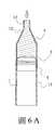
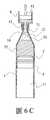
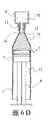
請參閱圖5至圖6D所示,前述結構應用於血液7分離以收集PRP 73的步驟簡述如下:5-1.首先,將血液7置入該管狀容器1內的該容置空間11(圖6A),然後將該管口蓋3與該底蓋4鎖緊,使該容置空間11成為密閉的結構;5-2.將該管狀容器1置入該離心機,開始進行離心作業,施加的離心力約為100g~4000g,時間約為5~20分鐘;5-3.此時該血液7分離為三層,上層為淡黃色的血漿71,下層為深紅色的紅血球72,而上、下層交界的中層為淡灰色的PRP 73(圖6B);5-4.將該管狀容器1前端銜接一注射筒8,然後將該注射筒8的內桿81後拉,造成該注射筒8內產生負壓,因此吸引該容置空間11上層的該血漿71往該注射筒8內移動,取出上層的該血漿71(圖6C);以及5-5.將該注射筒8移除,於該管狀容器1前端銜接另一注射筒8',然後將該推桿6插入該固定柱5,並對該推桿6施力推動該固定柱5使該活塞2在該管狀容器1內前進,因而將該PRP 73推入該注射筒8’中,完成該PRP 73的收集(圖6D)。Please refer to FIG. 5 to FIG. 6D, the steps of the aforementioned structure applied to the separation of
由前述結構與步驟得知,本發明同時具有該注射筒8、8'抽取血液7成分或是以該活塞2擠出血液7成分的方式,可視需要靈活調度,以更為方便且精確的取得所需的PRP 73。It is known from the foregoing structure and steps that the present invention also has a method of drawing
請復參閱圖1、圖2所示,本發明的重要特徵,在於該錐體12的設置,當該PRP 73要導出該管狀容器1進行收集時,由於該管狀容器1的前端逐漸縮減,該PRP 73會在該錐體12處的該容置空間11內產生聚集,因此該PRP 73的濃度大為增加,進而提升該PRP 73的收集率。Please refer to FIG. 1 and FIG. 2 again. The important feature of the present invention lies in the arrangement of the
而該錐體12的後端端面與該錐體的周圍壁面之間形成有錐體角度θ,為取得較佳的該錐體角度θ,發明人根據不同的錐體角度θ分別實驗,取得該PRP 73的收集率如下表:

由上表得知,該PRP 73的收集率的收集率會隨著該錐體12的該錐體角度θ增加而提高,本發明的較佳該錐體角度θ設定為25度至85度。It can be known from the above table that the collection rate of the collection rate of the
請復參閱圖6C、圖6D,本發明的該柱體13也可便於收集該PRP 73,該柱體13可與公規的該注射筒8前端緊密結合,並使該注射筒8的前端深入該引道14而到達該錐體12與該柱體13的連接端,增加收集PRP 73時的濃度以及避免污染,該柱體13前端也可連接三向閥(圖未示出)以進行連接作業。Please refer to FIG. 6C and FIG. 6D again. The
同樣的,如圖1至圖3,圖6C至圖6D所示,該柱體13的外表面可設置有螺紋131,用來與公規的該注射筒8進行連接,然後利用該螺紋131方式增加連接的緊密性。Similarly, as shown in FIGS. 1 to 3 and FIGS. 6C to 6D, the outer surface of the
再參圖1至圖3所示,該管口蓋3與該底蓋4同樣設置有螺紋31、41,以相對於該柱體13外表面的該螺紋131以及該管狀容器1的該開口16外表面的螺紋161進行連接,增加該管狀容器1封閉時的密閉性。Referring again to FIGS. 1 to 3, the
請參閱圖圖3、圖4、圖6D所示,該推桿6前端連接該固定柱5,以推動該固定柱5與該活塞2移動,為避免該推桿6連接該固定柱5不確實而造成抖動,影響收集該PRP 73的品質,故在該推桿6與該固定柱5之間以螺紋51、61方式連接,當該推桿6與該固定柱5以螺紋51、61緊密結合,即可穩定的推動該活塞2移動,提高該PRP 73收集的品質。Please refer to FIG. 3, FIG. 4 and FIG. 6D, the front end of the
又如圖4所示,該推桿6為細長的結構,即使以螺紋61方式連接,仍有可以因左右擺動而影響該PRP 73的收集,故本發明在該底蓋4中間設置有一穿孔,讓該推桿6穿過該穿孔而與該固定柱5連接,利用該穿孔位置提供該推桿6的支持,該推桿6無需依靠該螺紋51、61即可直接推動該固定柱5,使該推桿6推動時更加穩定,提高該PRP 73收集的品質。As shown in FIG. 4 again, the
或者,進一步在該推桿6與該底蓋4的該穿孔之間互設有螺紋62、42,使該推桿6利用該螺紋62、42緩慢轉動該活塞2,使該推桿6更加穩定、精確的移動該活塞2,提高該PRP 73收集的品質。Alternatively,
另外,請參圖3、圖4所示,該活塞2為軟質彈性結構,例如橡膠、矽膠,受到壓力時會擴張而迫緊該管狀容器1;而本發明進一步在該活塞2與該固定柱5之間設置具有一緩衝空間21,使該活塞2受到壓力時更容易擴張變形,維持該容置空間11內的氣密性。In addition, please refer to Figure 3 and Figure 4, the
更進一步,如圖1所示,為方便計算所收集的PRP 73成分容量,該管狀容器1、錐體12、柱體13表面設置有刻度17,可在集中PRP 73時即時計算收集的容量;利用該液體分離裝置100表面的刻度17,並用該推桿6控制該活塞2停止位置,可以得到不同的該高濃度血小板血漿,包括多白血球-高濃度血小板血漿、低白細胞-高濃度血小板血漿。Furthermore, as shown in FIG. 1, in order to facilitate calculation of the collected
或如圖7所示,該柱體13上設置有一凸透鏡18,該凸透鏡18得以放大該血液7各成分之間的連接端,以提高PRP 73的收集品質。Or, as shown in FIG. 7, a
利用前述本發明的液體分離裝置100,經實際操作時,確實可以增加收集該PRP 73的便利性,增加工作的效率,同時大幅增加該PRP 73收集的品質,使該PRP 73的使用更能符合需求,同時減少污染的可能性,也能進一步提高安全性。With the aforementioned
以上該僅為本發明之較佳實施例,並非用來限定本發明之實施範圍;如果不脫離本發明之精神和範圍,對本發明進行修改或者等同替換,均應涵蓋在本發明申請專利範圍的保護範圍當中。The above are only preferred embodiments of the present invention and are not intended to limit the scope of implementation of the present invention; if modifications or equivalent replacements of the present invention are made without departing from the spirit and scope of the present invention, they should be covered in the patent application scope of the present invention. In the scope of protection.
100‧‧‧液體分離裝置100‧‧‧liquid separation device
1‧‧‧管狀容器1‧‧‧tubular container
12‧‧‧錐體12‧‧‧Cone
13‧‧‧柱體13‧‧‧Cylinder
131‧‧‧螺紋131‧‧‧Thread
15‧‧‧管口15‧‧‧ nozzle
161‧‧‧螺紋161‧‧‧Thread
17‧‧‧刻度17‧‧‧Scale
2‧‧‧活塞2‧‧‧ Piston
3‧‧‧管口蓋3‧‧‧tube cover
4‧‧‧底蓋4‧‧‧Bottom cover
41‧‧‧螺紋41‧‧‧Thread
5‧‧‧固定柱5‧‧‧Fixed column
Claims (9)
Translated fromChinesePriority Applications (1)
| Application Number | Priority Date | Filing Date | Title |
|---|---|---|---|
| TW107110874ATWI689351B (en) | 2018-03-29 | 2018-03-29 | Liquid separation device and method of use |
Applications Claiming Priority (1)
| Application Number | Priority Date | Filing Date | Title |
|---|---|---|---|
| TW107110874ATWI689351B (en) | 2018-03-29 | 2018-03-29 | Liquid separation device and method of use |
Publications (2)
| Publication Number | Publication Date |
|---|---|
| TW201941832A TW201941832A (en) | 2019-11-01 |
| TWI689351Btrue TWI689351B (en) | 2020-04-01 |
Family
ID=69184487
Family Applications (1)
| Application Number | Title | Priority Date | Filing Date |
|---|---|---|---|
| TW107110874ATWI689351B (en) | 2018-03-29 | 2018-03-29 | Liquid separation device and method of use |
Country Status (1)
| Country | Link |
|---|---|
| TW (1) | TWI689351B (en) |
Families Citing this family (2)
| Publication number | Priority date | Publication date | Assignee | Title |
|---|---|---|---|---|
| TWI769760B (en)* | 2021-03-25 | 2022-07-01 | 國立臺灣大學 | Sampling device, semi-automatic sample feeding device and test paper detection system |
| CN117223795A (en)* | 2023-09-26 | 2023-12-15 | 青岛逢时宠科生物技术有限公司 | Pet feed prepared from antarctic krill oil and preparation method thereof |
Citations (1)
| Publication number | Priority date | Publication date | Assignee | Title |
|---|---|---|---|---|
| TWM546229U (en)* | 2017-04-25 | 2017-08-01 | Perfect Medical Industry Co Ltd | Injection syringe with safety needle cover |
- 2018
- 2018-03-29TWTW107110874Apatent/TWI689351B/enactive
Patent Citations (1)
| Publication number | Priority date | Publication date | Assignee | Title |
|---|---|---|---|---|
| TWM546229U (en)* | 2017-04-25 | 2017-08-01 | Perfect Medical Industry Co Ltd | Injection syringe with safety needle cover |
Also Published As
| Publication number | Publication date |
|---|---|
| TW201941832A (en) | 2019-11-01 |
Similar Documents
| Publication | Publication Date | Title |
|---|---|---|
| JP6324377B2 (en) | A device that extracts, stores and / or processes blood or other substances of human or animal origin and applies blood compounds or other biological compounds | |
| US3181529A (en) | Valved body-fluid sampling tubes | |
| US20190343261A1 (en) | Dropper-Type Cosmetics Container | |
| ES2675824B1 (en) | CONTAINER DEVICE FOR THE COLLECTION, STORAGE AND PROCESSING OF BLOOD OR A BLOOD COMPOUND | |
| JP3213458U (en) | Versatile sample collector | |
| JPWO2006132041A1 (en) | Sample collection liquid container | |
| TWI689351B (en) | Liquid separation device and method of use | |
| CN206675532U (en) | Multipurpose sample collector | |
| CN110433969A (en) | Liquid separating appts and its application method | |
| CN204618909U (en) | a sputum collector | |
| CN211583178U (en) | Disposable peripheral blood collector | |
| CN204394536U (en) | A kind of visible blood-back blood taking needle | |
| CN206583673U (en) | A kind of medical use liquid sample attracts collector | |
| US20190374939A1 (en) | Liquid separation device and its method of usage | |
| CN208017874U (en) | Molten syringe | |
| CN209137486U (en) | A kind of storage that blood circulation uses and filter device | |
| CN219104437U (en) | Sealed sampling mechanism | |
| CN204274477U (en) | Novel negative pressure blood collection and conservator | |
| CN208049128U (en) | A kind of straight type remaining needle of operation | |
| TWM506604U (en) | Container structure | |
| CN205598353U (en) | Bottle stopper puncture device | |
| CN210863239U (en) | A semen collection cup for convenient sampling and detection | |
| CN205868298U (en) | Can prolong formula rubber head drip tube | |
| CN104840223B (en) | A kind of saliva sample collection container | |
| CN204744195U (en) | Container structure |