TWI689277B - Charging base of electric vacuum cleaner - Google Patents
Charging base of electric vacuum cleanerDownload PDFInfo
- Publication number
- TWI689277B TWI689277BTW107107435ATW107107435ATWI689277BTW I689277 BTWI689277 BTW I689277BTW 107107435 ATW107107435 ATW 107107435ATW 107107435 ATW107107435 ATW 107107435ATW I689277 BTWI689277 BTW I689277B
- Authority
- TW
- Taiwan
- Prior art keywords
- vacuum cleaner
- electric vacuum
- nozzle
- extension tube
- standard
- Prior art date
Links
- 239000000428dustSubstances0.000description39
- 238000004140cleaningMethods0.000description26
- 239000000758substrateSubstances0.000description13
- 244000007853Sarothamnus scopariusSpecies0.000description12
- NJPPVKZQTLUDBO-UHFFFAOYSA-NnovaluronChemical compoundC1=C(Cl)C(OC(F)(F)C(OC(F)(F)F)F)=CC=C1NC(=O)NC(=O)C1=C(F)C=CC=C1FNJPPVKZQTLUDBO-UHFFFAOYSA-N0.000description9
- 230000005484gravityEffects0.000description7
- 238000010586diagramMethods0.000description5
- 238000012423maintenanceMethods0.000description3
- 230000003068static effectEffects0.000description3
- 238000005452bendingMethods0.000description2
- 210000000078clawAnatomy0.000description2
- 239000002245particleSubstances0.000description2
- 238000003825pressingMethods0.000description2
- HBBGRARXTFLTSG-UHFFFAOYSA-NLithium ionChemical compound[Li+]HBBGRARXTFLTSG-UHFFFAOYSA-N0.000description1
- 238000010276constructionMethods0.000description1
- 238000001035dryingMethods0.000description1
- 210000004247handAnatomy0.000description1
- 229910001416lithium ionInorganic materials0.000description1
- 230000003340mental effectEffects0.000description1
- 229910052751metalInorganic materials0.000description1
- 239000002184metalSubstances0.000description1
- 238000000034methodMethods0.000description1
- 238000012856packingMethods0.000description1
- 230000000630rising effectEffects0.000description1
- 239000004576sandSubstances0.000description1
- 238000007790scrapingMethods0.000description1
- 238000000926separation methodMethods0.000description1
- 238000009751slip formingMethods0.000description1
- 238000005406washingMethods0.000description1
- 210000000707wristAnatomy0.000description1
Images


Classifications
- A—HUMAN NECESSITIES
- A47—FURNITURE; DOMESTIC ARTICLES OR APPLIANCES; COFFEE MILLS; SPICE MILLS; SUCTION CLEANERS IN GENERAL
- A47L—DOMESTIC WASHING OR CLEANING; SUCTION CLEANERS IN GENERAL
- A47L9/00—Details or accessories of suction cleaners, e.g. mechanical means for controlling the suction or for effecting pulsating action; Storing devices specially adapted to suction cleaners or parts thereof; Carrying-vehicles specially adapted for suction cleaners
- A47L9/28—Installation of the electric equipment, e.g. adaptation or attachment to the suction cleaner; Controlling suction cleaners by electric means
- A47L9/2868—Arrangements for power supply of vacuum cleaners or the accessories thereof
- A47L9/2873—Docking units or charging stations
- A—HUMAN NECESSITIES
- A47—FURNITURE; DOMESTIC ARTICLES OR APPLIANCES; COFFEE MILLS; SPICE MILLS; SUCTION CLEANERS IN GENERAL
- A47L—DOMESTIC WASHING OR CLEANING; SUCTION CLEANERS IN GENERAL
- A47L9/00—Details or accessories of suction cleaners, e.g. mechanical means for controlling the suction or for effecting pulsating action; Storing devices specially adapted to suction cleaners or parts thereof; Carrying-vehicles specially adapted for suction cleaners
- H—ELECTRICITY
- H02—GENERATION; CONVERSION OR DISTRIBUTION OF ELECTRIC POWER
- H02J—CIRCUIT ARRANGEMENTS OR SYSTEMS FOR SUPPLYING OR DISTRIBUTING ELECTRIC POWER; SYSTEMS FOR STORING ELECTRIC ENERGY
- H02J7/00—Circuit arrangements for charging or depolarising batteries or for supplying loads from batteries
- H02J7/0042—Circuit arrangements for charging or depolarising batteries or for supplying loads from batteries characterised by the mechanical construction
Landscapes
- Engineering & Computer Science (AREA)
- Mechanical Engineering (AREA)
- Power Engineering (AREA)
- Robotics (AREA)
- Electric Vacuum Cleaner (AREA)
- Electric Suction Cleaners (AREA)
Abstract
Translated fromChineseDescription
Translated fromChinese本發明係有關一種電動吸塵器之充電座。The invention relates to a charging base of an electric vacuum cleaner.
專利文獻1中,記載有一種不用電線類型之電動吸塵器、及可將該電動吸塵器充電之充電座Patent Literature 1 describes an electric vacuum cleaner that does not use electric wires, and a charging stand that can charge the electric vacuum cleaner
[專利文獻1]日本特開2015-119879號公報[Patent Document 1] Japanese Patent Laid-Open No. 2015-119879
且說專利文獻1中所記載之電動吸塵器,其吸塵器本體之前部安裝有延長管,藉而可以桿式之狀態使用,而藉由自吸塵器本體卸下該延長管則可以手持狀態使用。如此般之將重心之位置設於手邊之位置的電動吸塵器已有各種提案。此種電動吸塵器,在充電之情形下,係將連接有吸嘴之延長管自本體卸下,而與本體各自分別地設定於充電座。於此一情形下,本體佔據之空間與連接有吸嘴之延長管佔據之空間乃成為必要,因此必須將置放充電座之空間確保為寬廣。Furthermore, the electric vacuum cleaner described in Patent Document 1 has an extension tube installed at the front of the vacuum cleaner body, so that it can be used in a rod state, and can be used in a hand-held state by removing the extension tube from the vacuum cleaner body. Various proposals have been made for electric vacuum cleaners with the center of gravity at the position at hand. In such an electric vacuum cleaner, in the case of charging, the extension tube connected with the suction nozzle is detached from the main body, and is separately set on the charging base with the main body. In this case, the space occupied by the body and the connection have suctionThe space occupied by the extension tube of the mouth is necessary, so the space for placing the charging base must be wide.
本發明之目的係在提供一種充電時可節省空間的電動吸塵器之充電座。The purpose of the present invention is to provide a charging base of an electric vacuum cleaner which can save space when charging.
本發明之構成上之特徵在於:具備載置於地板面之底座部、與自上述底座部立起之支座部;上述支座部具有可保持管之保持部,可收納連接有標準吸嘴之延長管,當將電動吸塵器以手持狀態充電之情形下,其收納位置在正視下落於標準吸嘴之左右寬×延長管之高所佔的區域內。The structure of the present invention is characterized by a base part placed on the floor surface and a stand part standing up from the base part; the stand part has a holding part capable of holding a tube, and a standard suction nozzle can be stored and connected When the electric vacuum cleaner is charged in a hand-held state, its storage position is in the area occupied by the left and right width of the standard suction nozzle × the height of the extension tube.
根據本發明,可提供在充電時節省空間的電動吸塵器之充電座。According to the present invention, it is possible to provide a charging stand for an electric vacuum cleaner that saves space during charging.
1:吸塵器本體1: Vacuum cleaner body
2:集塵盒2: dust box
3:蓄電池3: battery
10:本體部10: Body part
40:電動送風機40: Electric blower
50:本體基板(控制基板)50: main body substrate (control substrate)
70:充電座70: charging stand
71:底座部71: Base part
71e:延出部71e: Extension Department
72:支座部72: Support
72c:連結保持部72c: Link holding part
73:第1充電端子73: The first charging terminal
100:電動吸塵器100: electric vacuum cleaner
300:延長管300: Extension tube
400:標準吸嘴400: Standard nozzle
500、500A、500B:間隙吸嘴(應用吸嘴體)500, 500A, 500B: gap nozzle (application nozzle body)
600:小型吸嘴(應用吸嘴體)600: small nozzle (use nozzle body)
700:掃帚型吸嘴(應用吸嘴體)700: Broom nozzle (application nozzle body)
800:延長軟管(應用吸嘴體)800: Extension hose (use nozzle body)
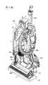
第1圖為於本實施方式之充電座安裝電動吸塵器等之狀態的立體圖。FIG. 1 is a perspective view of a state where an electric vacuum cleaner or the like is attached to the charging stand of this embodiment.
第2圖(a)為第1圖的俯視圖,(b)為第1圖的左側視圖,(c)為第1圖的正視圖,(d)為第1圖的右側視圖。Figure 2 (a) is a top view of Figure 1, (b) is a left side view of Figure 1, (c) is a front view of Figure 1, (d) is a right side view of Figure 1.
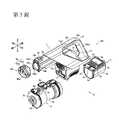
第3圖為電動吸塵器的分解立體圖。Figure 3 is an exploded perspective view of the electric vacuum cleaner.
第4圖為電動吸塵器的立體圖。Fig. 4 is a perspective view of an electric vacuum cleaner.
第5圖為電動吸塵器的縱剖視圖。Fig. 5 is a longitudinal sectional view of the electric vacuum cleaner.
第6圖為顯示電動吸塵器之充電座的立體圖。Fig. 6 is a perspective view showing a charging base of an electric vacuum cleaner.
第7圖(a)為第6圖的俯視圖,(b)為第6圖的左側視圖,(c)為第6圖的正視圖,(d)為第6圖的右側視圖。Figure 7 (a) is a top view of Figure 6, (b) is a left side view of Figure 6, (c) is a front view of Figure 6, (d) is a right side view of Figure 6.
第8圖為顯示電動吸塵器之充電座的分解立體圖。Fig. 8 is an exploded perspective view showing the charging base of the electric vacuum cleaner.
第9圖(a)為第8圖的俯視圖,(b)為第8圖的左側視圖,(c)為第8圖的正視圖,(d)為第8圖的右側視圖。Figure 9 (a) is a top view of Figure 8, (b) is a left side view of Figure 8, (c) is a front view of Figure 8, (d) is a right side view of Figure 8.
第10圖為顯示電動吸塵器之充電座之第1充電端子的放大立體圖。FIG. 10 is an enlarged perspective view showing the first charging terminal of the charging base of the electric vacuum cleaner.
第11圖為顯示將與充電座之第1充電端子連接的電動吸塵器之本體端子部,自集塵盒側仰視之狀態的立體圖。FIG. 11 is a perspective view showing a state in which the body terminal portion of the electric vacuum cleaner connected to the first charging terminal of the charging stand is viewed from the dust box side.
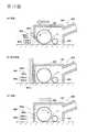
第12圖為顯示安裝有開閉構件之標準吸嘴的剖視圖,其中(a)為前進時,(b)為撞及壁面時,(c)為後退時。Fig. 12 is a cross-sectional view showing a standard nozzle equipped with an opening and closing member, wherein (a) is when it is advancing, (b) is when it hits a wall surface, and (c) is when it is receding.
第13圖顯示各種之應用吸嘴體,其中(a)為顯示間隙吸嘴的立體圖,(b)為顯示小型吸嘴的立體圖,(c)為顯示掃帚型吸嘴的立體圖。Figure 13 shows various application nozzle bodies, of which (a) is a perspective view showing a gap nozzle, (b) is a perspective view showing a small nozzle, and (c) is a perspective view showing a broom nozzle.
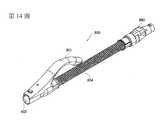
第14圖為顯示延長軟管的立體圖。Fig. 14 is a perspective view showing an extension hose.
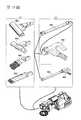
第15圖為附屬之附屬品之一覽與連接的組合圖。Figure 15 is a combined diagram of the list and connection of the attached accessories.
第16圖為顯示於本實施方式之充電座安裝電動吸塵器等之狀態的圖,其中(a)為立體圖,(b)為俯視圖,(c)為左側視圖,(d)為正視圖,(e)為右側視圖。FIG. 16 is a diagram showing a state where an electric vacuum cleaner or the like is mounted on the charging stand of the present embodiment, where (a) is a perspective view, (b) is a plan view, (c) is a left side view, (d) is a front view, (e ) Is the right side view.
第17圖為顯示安裝於充電座之狀態的圖,其中(a)為立體圖,(b)為俯視圖,(c)為左側視圖,(d)為正視圖,(e)為右側視圖。Figure 17 is a diagram showing the state of being mounted on the charging stand, where (a) is a perspective view, (b) is a top view, (c) is a left side view, (d) is a front view, and (e) isRight side view.
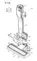
第18圖為利用桿式狀態之電動吸塵器清掃地板面時的使用形態圖。Fig. 18 is a view of the usage form when the floor surface is cleaned by the electric vacuum cleaner in the rod state.
第19圖為利用桿式狀態之電動吸塵器清掃高的場所時的使用形態圖。Fig. 19 is a view of the use form when cleaning a high place with a rod-type electric vacuum cleaner.
以下,針對用以實施本發明之方式(以下稱為「實施方式」),參照適當圖面詳細進行說明。Hereinafter, a mode for implementing the present invention (hereinafter referred to as an "embodiment") will be described in detail with reference to appropriate drawings.
第1圖為於本實施方式之充電座安裝電動吸塵器等之狀態的立體圖。第2圖(a)為第1圖的俯視圖,(b)為第1圖的左側視圖,(c)為第1圖的正視圖,(d)為第1圖的右側視圖。第16圖為顯示於本實施方式之充電座安裝電動吸塵器等之狀態的圖,其中(a)為立體圖,(b)為俯視圖,(c)為左側視圖,(d)為正視圖,(e)為右側視圖。第17圖為顯示安裝於充電座之狀態的圖,其中(a)為立體圖,(b)為俯視圖,(c)為左側視圖,(d)為正視圖,(e)為右側視圖。FIG. 1 is a perspective view of a state where an electric vacuum cleaner or the like is attached to the charging stand of this embodiment. Figure 2 (a) is a top view of Figure 1, (b) is a left side view of Figure 1, (c) is a front view of Figure 1, (d) is a right side view of Figure 1. FIG. 16 is a diagram showing a state where an electric vacuum cleaner or the like is mounted on the charging stand of the present embodiment, where (a) is a perspective view, (b) is a plan view, (c) is a left side view, (d) is a front view, (e ) Is the right side view. FIG. 17 is a diagram showing a state of being mounted on a charging stand, wherein (a) is a perspective view, (b) is a top view, (c) is a left side view, (d) is a front view, and (e) is a right side view.
第1圖係於電動吸塵器100之充電座70將電動吸塵器100等以手持狀態豎立充電的狀態。電動吸塵器100之前部直接安裝有間隙/毛刷切換嘴110。充電座70上安裝有延長管300、延長軟管800、及小型吸嘴600。又,標準吸嘴400安裝於延長管300之前端。FIG. 1 shows a state where the charging stand 70 of the
第3圖為電動吸塵器的分解立體圖。第4圖為電動吸塵器的立體圖。第5圖為電動吸塵器的縱剖視圖。Figure 3 is an exploded perspective view of the electric vacuum cleaner. Fig. 4 is a perspective view of an electric vacuum cleaner. Fig. 5 is a longitudinal sectional view of the electric vacuum cleaner.
再者,第2圖中表示之方向係電動吸塵器100之朝向。In addition, the direction shown in FIG. 2 is the direction of the
如第2圖所示,電動吸塵器100係具備吸塵器本體1、集塵盒2(集塵裝置)及蓄電池3而構成。As shown in FIG. 2, the
吸塵器本體1係具備本體部10、馬達箱部11、及手把部12而構成。The cleaner body 1 includes a
本體部10上形成有供延長管300(參見第1圖)或標準吸嘴400連接之連接口10a。又,本體部10上固定脫離自如地安裝有集塵盒2,且具備將自連接口10a吸入之含有塵埃之空氣送入集塵盒2的導入管14。The
馬達箱部11中內含電動送風機40(參見第5圖)與本體基板50(參見第5圖)。又,馬達箱部11之前面,形成有吸入由集塵盒2所集塵後的潔淨空氣的圓形吸入口11a。另外,馬達箱部11之前面,較吸入口11a更下部,設有與充電座70(參見第1圖)連接之本體端子部17。The
手把部12係設於本體部10之後方,具有形成為大致L字形之把持部12a。把持部12a具有於前後方向直線狀延伸之第1把持部12a1、及於大致上下方向直線狀延伸之第2把持部12a2。第1把持部12a1較第2把持部12a2配置於上部。第2把持部12a2相對上下方向以上部朝向前方之方式傾斜。又,第1把持部12a1與第2把持部12a2大致成棒狀且連續形成。如此,藉由將第1把持部12a1與第2把持部12a2分別構成為直線狀,而使得使用者易於辨識手把之位置。The
另外,於手把部12設有用以鎖定蓄電池3(電池盒)之蓄電池鎖定構件13。此一蓄電池鎖定構件13係形成為大致L字形之板狀,以一端旋動自如地連結於手把部12。In addition, a
又,手把部12之第1把持部12a1的上面,設有操作按鈕12b。操作按鈕12b,例如係以「強」、「標準」、「切斷」之3個按鈕構成。In addition, an
本體部10之前端,設有在卸下延長管300(參見第1圖)或標準吸嘴400(參見第1圖)時供操作之解除按鈕18。藉由按下操作此一解除按鈕18,可卸下延長管300、標準吸嘴400。The front end of the
又,本體部10之前端,安裝有旋轉式之毛刷90。此一毛刷90在構成上具有:凹凸嵌合於連接口10a之外面而固定的大致圓弧形狀之固定座部90a、旋動自如地連結於此固定座部90a之旋轉部90b、及植設於此旋轉部90b之刷毛部90c。刷毛部90c在構成上於收納時係朝後、於使用時係朝前旋動。In addition, a
集塵盒2係旋風分離方式者,具有將自導入管14吸入之含有塵埃的空氣分離為塵埃與空氣,並將塵埃收集之功能。又,集塵盒2於馬達箱部11之前方以軸向為前後方向地配置,具有大致圓柱形狀之收容部2a。此外,集塵盒2之上面(側面),形成有與導入管14相連之大致矩形之流入口2b。流入此一流入口2b之含有塵埃的空氣,於集塵盒2內經分離為塵埃與空氣後,塵埃經分離之空氣自集塵盒2之後部(背面)排出。The
又,集塵盒2之前面上,經由鉸鍊部2d而旋動自如地支持有將集塵盒2內積留之塵埃廢棄時供開閉的蓋2c。此外,蓋2c之上部,設有用以解除蓋2c之鎖定的蓋鎖定機構2e。另外,有關集塵盒2之內部之機構,可基於日本特開2016-137165號公報而構成。Also, the front surface of the
如第4圖所示,電動吸塵器100中,集塵盒2係安裝於本體部10之下方且馬達箱部11之前方。此一情形下,若將集塵盒2裝設於吸塵器本體1,則蓋鎖定機構2e將隱蔽於吸塵器本體1側。其原因在於,在將蓋鎖定機構2e設於相反側(外側)之情況下,在清掃中蓋鎖定機構2e會有解除之顧慮,但若藉由使蓋鎖定機構2e隱蔽於吸塵器本體1側,則可防止錯誤動作。例如,若以桿式狀態清掃沙發下或床下時等,會有將吸塵器本體1相對地板面水平接近之情況。此時,於蓋鎖定機構2e設於表側之情況下,會有與地板面接觸而蓋鎖定機構2e遭解除的可能性。蓋鎖定機構2e與鉸鍊部2d之位置不限於此,也可相對於吸塵器本體1設於左右。As shown in FIG. 4, in the
又,於集塵盒2中,固定脫離自如地設有維護毛刷2s。此一維護毛刷2s係配置於在集塵盒2裝設於吸塵器本體1時自外部不易看到的位置。因此,在運轉中不易脫落,而且也無將維護毛刷2s預予保管於與電動吸塵器100不同之場所的必要。In addition, in the
如第5圖所示,本體部10之馬達箱部11中收容有電動送風機40。於馬達箱部11內,在電動送風機40之下方,收容有控制吸塵器本體1之本體基板50(控制基板)。As shown in FIG. 5, an
電動送風機40係以旋轉驅動軸40a朝向前後方向之方式配置成橫置型。又,自電動送風機40排出之空氣,係流至電動送風機40之下方配置的本體基板50,而將本體基板50冷卻。The
本體基板50係上下分割而配置成2段,主要是在對向面上安裝零件。自電動送風機40排出之幾乎所有空氣,係以將各本體基板50之對向配置的零件(發熱零件)冷卻的方式流動。The
另外,電動送風機40與本體基板50係以上下方向重疊的方式配置。因此,可將前後方向之尺寸設為短。又,電動送風機40及本體基板50,係位於手把部12之第1把持部12a1之下方。藉此,使用者在握持把持部12a1而進行操作的情形下,電動吸塵器100之重心將成為第1把持部12a1之下方附近,因此在將電動吸塵器100之前部朝上而使用的情況下,可將電動吸塵器100穩定地保持。In addition, the
又,第1把持部12a1與馬達箱部11之上面11c之間,形成有供手插入之寬度尺寸H1的間隙12c。而且第2把持部12a2與馬達箱部11之背面11d之間,形成有較寬度尺寸H1為寬廣之寬度尺寸H2的間隙12d。如此,在把持第1把持部12a1進行清掃之情形下,可以伸出手臂之狀態予以保持,因此可在不強力握持第1把持部12a1下,將電動吸塵器100前後移動。此外,在把持第2把持部12a2進行清掃之情形下,由於有於間隙12d中深深地插入手(指)強力地握住之必要,因此藉由將寬度尺寸H2設為較寬度尺寸H1寬廣,可穩定地把持第2把持部12a2。In addition, between the first grip portion 12a1 and the
又,第1把持部12a1之厚度T1形成為薄,第2把持部12a2之厚度T2形成為較厚度T1為厚。亦即,第1把持部12a1形成為細,第2把持部12a2形成為粗。如此,在握持第2把持部12a2進行清掃之情形下,藉由將第2把持部12a2之厚度T2設為厚,除易於緊密握住之外,還可提高第2把持部12a2之強度。In addition, the thickness T1 of the first grip portion 12a1 is formed to be thin, and the thickness T2 of the second grip portion 12a2 is formed to be thicker than the thickness T1. That is, the first grip portion 12a1 is formed to be thin, and the second grip portion 12a2 is formed to be thick. In this way, in the case of cleaning by holding the second grip portion 12a2, by making the thickness T2 of the second grip portion 12a2 thick, the strength of the second grip portion 12a2 can be increased in addition to easy gripping.
蓄電池3例如可以能源效率高的鋰離子電池構成。又,蓄電池3係配置於手把部12之第2把持部12a2的下方。如此,藉由將蓄電池3設置於電動吸塵器100之後端,手把部12之重心將變成接近第2把持部12a2,因此在將電動吸塵器100之前部而朝上使用之情形下,可使操作感輕便。The
蓄電池鎖定構件13,其自由端側形成有與蓄電池3鎖定之爪部13a。另,蓄電池鎖定構件13在構成上係以將蓄電池3之背面自上端至下端包圍之方式配置,而於蓄電池3之後端下面,爪部13a與蓄電池3之下面鎖定。The
如是,藉由將蓄電池3設為裝卸式,與蓄電池不可裝卸式者相比,蓄電池3之更換變得容易。而且,藉由選擇性地準備預備之蓄電池3、及可將預備之蓄電池3充電之充電箱,在電動吸塵器100之本體側的蓄電池蓄電耗盡之情形下,可與預備之蓄電池3直接更換,藉而可延長清掃時間。藉由如是般之構成,例如在清掃店舖等之廣大的地板面之情形下有效。If so, by setting the
集塵盒2內,於收容部2a之軸向的後端收容有過濾器5。此一過濾器5係彎折成摺狀而構成者,除可增大過濾器面積外,還可降低過濾器5所導致之壓力損失。In the
再者,過濾器5例如可由高密度之HEPA過濾器(High Efficiency Particulate Air Filter,高效率微粒空氣過濾器)構成。HEPA過濾器係指具有在額定風量下相對粒徑0.3μm之粒子具有99.97%以上之粒子捕集率、且初始壓力損失為245Pa以下之性能的空氣過濾器。Furthermore, the
根據如是構成之電動吸塵器100,使用者若操作設於手把部12之操作按鈕12b(參見第4圖)而開始運轉,則電動送風機40(參見第5圖)自蓄電池3(參見第4圖)被供電。而後,電動送風機40驅動而吸入空氣。吸入之空氣係經由導入管14(參見第5圖),經過流入口2b(參見第3圖)而流入集塵盒2內。而後,流入之含有塵埃的空氣將會成為旋流,對於塵埃作用以離心力,而塵埃與空氣被分離。之後,空氣通過過濾器5,再經由電動送風機40、本體基板50(參見第5圖),而自排氣口排出至吸塵器本體1之外部。According to the
第6圖為顯示電動吸塵器之充電座的立體圖。又,第9圖中所示之充電座70,係將電氣吸塵器100及所有之應用吸嘴體(附屬品)卸除之狀態。Fig. 6 is a perspective view showing a charging base of an electric vacuum cleaner. In addition, the charging
如第6圖所示,充電座70在構成上具備底座部71及支座部72。As shown in FIG. 6, the charging
底座部71具有供載置標準吸嘴400(參見第1圖)之大致矩形狀之載置面71a。又,底座部71於寬度方向(左右方向)之中央,具有向後方延伸之延出部71b。此一延出部71b之左右的側方,設有用以供將後述應用吸嘴體安裝而預予保管之側部保管部71c、71d。The
第7圖(a)為第6圖的俯視圖,(b)為第6圖的左側視圖,(c)為第6圖的正視圖,(d)為第6圖的右側視圖。Figure 7 (a) is a top view of Figure 6, (b) is a left side view of Figure 6, (c) is a front view of Figure 6, (d) is a right side view of Figure 6.
如第7圖所示,右側之側部保管部71c在構成上具有:自延出部71b朝右側方延出而與地板面相接之台座部71c1、以及自該台座部71c1之上面朝上方突出的圓柱形狀之突起部71c2。左側之側部保管部71d在構成上具有:自延出部71b朝左側方延出而與地板面相接之台座部71d1、以及自該台座部71d1之上面朝上方突出的圓柱形狀之突起部71d2。As shown in FIG. 7, the right
又,延出部71b中,朝後方延出之延出部71e係與底座部71一體形成。此一延出部71e,具有在電動吸塵器100充電時,防止電動吸塵器100朝後方傾倒之功能。又,延出部71e具有:與地板面相接之台座部71e1、及自該台座部71e1之上面朝上方突出之圓柱形狀之吸嘴保管部71e2。再者,台座部71e1係朝左右方向延出而寬廣地構成。另外,台座部71e1之左右方向的兩端,係較上述台座部71c1、71d1之前端更位於內側(參見第10圖)。如此,延出部71e不僅具有防止電氣吸塵器100之傾倒之功能,還具有供安裝應用吸嘴體而預予保管之保管功能。In the
如第7圖所示,支座部72係自延出部71b之後端部朝鉛直方向(上下方向)往上延伸。又,支座部72係形成為自上下方向之中央,上部較下部更於前後方向具有厚度。As shown in FIG. 7, the
支座部72之上面72a之上,設有在將手持狀態之電動吸塵器100(參見第1圖)充電時使用之第1充電端子73。第1充電端子73係與吸塵器本體1(參見第2圖)電性連接。又,第1充電端子73係將蓄電池3充電之端子,且形成為自支座部72之上面72a朝鉛直方向之上方突出。Above the
第8圖為顯示電動吸塵器之充電座的分解立體圖。第9圖(a)為第8圖的俯視圖,(b)為第8圖的左側視圖,(c)為第8圖的正視圖,(d)為第8圖的右側視圖。Fig. 8 is an exploded perspective view showing the charging base of the electric vacuum cleaner. Figure 9 (a) is a top view of Figure 8, (b) is a left side view of Figure 8, (c) is a front view of Figure 8, (d) is a right side view of Figure 8.
如第8圖所示,充電座70在構成上,支座部72相對底座部71係固定脫離自如。又,底座部71與支座部72也可非為固定脫離自如,但為了提升收納性暨捆包性,較佳的是固定脫離自如。As shown in FIG. 8, the charging
底座部71在後面具有電源電線76,在內部具有充電基板74。又,底座部71之內部設有配重75,使得在充電座70裝設電動吸塵器100時充電座70不易傾倒。The
支座部72上設有連接插腳72b,底座部71上設有接納連接插腳72b之連接端子71f,藉由於底座部71裝設支座部72,連接插腳72b與連接端子71f電性連接。又,連接插腳72b與第1充電端子73,係經由圖未示之電線連接。The
第10圖為顯示電動吸塵器之充電座之第1充電端子的放大立體圖。FIG. 10 is an enlarged perspective view showing the first charging terminal of the charging base of the electric vacuum cleaner.
如第10圖所示,第1充電端子73具有自支座部72之上面72a朝上方突出之大致長方體形狀之端子台73a。此一端子台73a係形成為左右方向細長。又,端子台73a上,於左右兩端形成有以前面及上面開放之方式切缺成之凹部73b、73b。各凹部73b內設有端子73c。端子73c在支座部72內係以螺釘固定。As shown in FIG. 10, the first charging
端子台73a上,於端子73c與端子73c之間,形成有以前面及上面開放之方式切缺成之大致長方體形狀之凹入部73d、73d。On the
端子73c係藉由彎折細長金屬板而構成,於凹部73b內係以可於前後方向撓曲變形之方式配置。又,端子73c係經由引線(圖未示)與上述之連接插腳72b電性連接。The terminal 73c is formed by bending an elongated metal plate, and is arranged in the
第11圖為顯示將與充電座之第1充電端子連接的電動吸塵器之本體端子部,自集塵盒側仰視之狀態的立體圖。FIG. 11 is a perspective view showing a state in which the body terminal portion of the electric vacuum cleaner connected to the first charging terminal of the charging stand is viewed from the dust box side.
第11圖所示,吸塵器本體1之本體端子部17上,形成有供充電座70之端子台73a(參見第10圖)嵌合的嵌合凹部17a。嵌合凹部17a內,配置有與充電座70之端子73c(參見第10圖)連接的本體端子17b。此一本體端子17b係與蓄電池3(參見第2圖)經由電線而電性連接。又,嵌合凹部17a內,形成有與充電座70之凹入部73d(參見第10圖)嵌合之嵌合突起17c。As shown in FIG. 11, the
於本體端子部17嵌合於第1充電端子73時,本體端子17d與端子73c接觸,進而本體端子17d之緣部17f下降,藉此端子73c朝後方撓曲變形。端子73c由於具有朝前方彈推之彈性,因此於吸塵器本體1裝設於充電座70之期間,本體端子17d與端子73c維持於接觸之狀態,使得對於蓄電池3(參見第3圖)之充電繼續。When the
又,第1充電端子73係與本體端子部17凹凸嵌合,因此例如充電中即使使用者接觸了吸塵器本體1,本體端子17d與端子73c之導通狀態(接觸狀態)不會解除。In addition, since the first charging
如此構成之充電座70中,由於第1充電端子73形成於支座部72之上面72a,因此在將第1充電端子73與本體端子部17對接時,乃位於與使用者之視線接近的位置,故而本體端子部17易於插入第1充電端子73,使得易於將吸塵器本體1設定於充電座70。In the charging
又,充電座70中,第1充電端子73係形成於支座部72之上面72a。亦即,第1充電端子73形成於較地板面為高的位置,因此垃圾不易堆積於第1充電端子73,而且可減少塵埃自地板面揚起而附著之情事。In the charging
又,設定於充電座70之電動吸塵器100中,在近於電動吸塵器100之重心的位置(電動送風機40及蓄電池3之位置),有第1充電端子73位於該處,因此其重心附近係由第1充電端子73承受,藉而在充電中可將吸塵器本體1穩定地保持於充電座70。In addition, in the
又,由於將電動吸塵器100應用於充電座70,可在將集塵盒2卸下之狀態下充電,因此在將集塵盒2洗淨、乾燥之過程中亦可充電。In addition, since the
又,第1充電端子73係構成為朝上,且本體端子部17自上方與第1充電端子73連接。藉此,可將電動吸塵器100之本身重量重點地作用於第1充電端子73,因此可將本體端子部17與第1充電端子73確實地連接。In addition, the first charging
又,充電座70中,於電動吸塵器100連接有標準吸嘴400的狀態下進行充電之情形下,可利用底座部71之載置面71a予以支持,因此可將電動吸塵器100由第1充電端子73與標準吸嘴400之2個部位支持,而可將電動吸塵器100穩定地保持於充電座70。In addition, in the charging
第18圖為利用桿式狀態之電動吸塵器清掃地板面時的使用形態圖。Fig. 18 is a view of the usage form when the floor surface is cleaned by the electric vacuum cleaner in the rod state.
如第18圖所示,將電動吸塵器100設為桿式狀態,將電動吸塵器100較使用者更朝前方突出而清掃地板面的情形下,使用者一面把持手把部12之第2把持部12a2,一面使電動吸塵器100前後移動。又,圖中並未表示的是,在電動吸塵器100位於使用者之腋下的狀態下進行地板面的清掃之情形下,使用者乃一面把持手把部12之第1把持部12a1,一面使電動吸塵器100前後移動。如此,在使用者清掃地板面之情形下,係改換手把部12之持拿位置進行清掃。As shown in FIG. 18, when the
第19圖為利用桿式狀態之電動吸塵器清掃高的場所時的使用形態圖。Fig. 19 is a view of the use form when cleaning a high place with a rod-type electric vacuum cleaner.
且說在設為桿式狀態時,重心位於前端側之電動吸塵器(參見專利文獻1)中,將電動吸塵器100在較地板面為高的場所進行清掃之情形下,使用者有必要將電動吸塵器100的前部朝上舉起,而易於對手腕施加負擔。Moreover, when the rod-type state is set, the center of gravity is located at the front end of the electric vacuum cleaner (see Patent Document 1), and the
為此,由於電動吸塵器100之重物即電動送風機40(參見第5圖)與蓄電池3係位於接近手把部12之位置(近於手邊之位置),因此電動吸塵器100之重心G變得接近使用者之手邊。藉此,即便將電動吸塵器100設為桿式狀態,以電動吸塵器100清掃較地板面為高的場所之情形下,清掃也屬容易,可提升使用便利性。第19圖中,係以清掃階梯之情形舉例說明,但在將電動吸塵器100舉起而清掃空調之面板等的情形下也屬有效。For this reason, since the electric blower 40 (see FIG. 5), which is the heavy object of the
其次,針對連接於電動吸塵器100之各種應用吸嘴體進行說明。可在上述電動吸塵器100上,作為附屬品更換連接之各種應用吸嘴體進行清掃。Next, various application nozzle bodies connected to the
第12圖為顯示安裝有開閉構件之標準吸嘴的剖視圖,其中(a)為前進時,(b)為撞及壁面時,(c)為後退時。又,第12圖中,省略驅動旋轉毛刷之馬達與控制旋轉毛刷之基板的圖示。Fig. 12 is a cross-sectional view showing a standard nozzle equipped with an opening and closing member, wherein (a) is when it is advancing, (b) is when it hits a wall surface, and (c) is when it is receding. In addition, in FIG. 12, illustrations of the motor driving the rotating brush and the substrate controlling the rotating brush are omitted.
如第12圖(a)所示,標準吸嘴400在構成上具有:吸嘴外殼401、由馬達(未圖示)驅動之第1毛刷402、藉由與地板面間之摩擦而旋轉之第2毛刷403。As shown in FIG. 12(a), the
吸嘴外殼401其下面開放,且具有收容第1毛刷402及第2毛刷403之空間。第2毛刷403係於第1毛刷402之後方隔開間隙而配置。The
又,吸嘴外殼401之前面設有開閉構件404。開閉構件404具有旋動軸404a。另,開閉構件404具有:以與旋動軸404a之軸向正交之方式延伸的突起體404b、及自旋動軸404a朝與突起體404b相反方向延伸的開閉體404c。突起體404b係由硬質之板狀構件構成。開閉體404c係由前側之刷毛部404c1與後側之橡膠製之片材404c2前後重合而構成。In addition, an opening and closing
如第12圖(a)所示,在使標準吸嘴400前進之情形下,藉由刷毛部404c1與地板面間之摩擦力、及電動送風機40之吸入力,使得開閉體404c朝反時鐘方向旋動,而吸嘴外殼401之前面下部成為開放狀態。如是,藉由開閉體404c開放,變得可吸入位於標準吸嘴400之前方的大型垃圾(塵埃)。As shown in FIG. 12(a), when the
如第12圖(b)所示,標準吸嘴400撞及壁面之情形下,首先突起體404b之前端(上端)撞及壁面。而後,若標準吸嘴400朝壁面進一步被按壓,則藉由此時之壓入力,開閉構件404朝時鐘方向旋動而開閉體404c朝前動作。藉由開閉體404c朝前動作,吸嘴外殼401之前面下部之開口401a被關閉。藉由如此般之構成,可吸入極靠近壁面(隅部)之垃圾而予除去。而且,藉由將標準吸嘴400於左右方向移動,可進一步確實除去極靠近壁面之垃圾。As shown in FIG. 12(b), when the
如第12圖(c)所示,於使標準吸嘴400後退之情形下,藉由刷毛部404c1與地板面間之摩擦力,開閉體404c朝時鐘方向旋動而開閉體404c朝前動作。藉此,吸嘴外殼401內之靜壓上升,據此可確實吸入垃圾。As shown in FIG. 12(c), when the
又,不用電線之電動吸塵器100,其吸入力較自家庭用之插座被供給電力之電動吸塵器為弱。因此,根據標準吸嘴400,在前進時(參見第12圖(a))吸嘴外殼401之前面(開口401a)開放,因此可減輕操作力,也可吸取大型垃圾。又,在後退時(參見第12圖(c)),開閉構件404關閉,靜壓升高,可確實吸入例如地毯中之砂粒垃圾等。另,標準吸嘴400在構成上係較自家庭用插座供給電力的電動吸塵器上所連接之吸嘴為小,據此可減小自標準吸嘴400之空氣的洩漏,且靜壓易於普遍性地均等。In addition, the
第13圖顯示各種之應用吸嘴體,其中(a)為顯示間隙吸嘴的立體圖,(b)為顯示小型吸嘴的立體圖,(c)為顯示掃帚型吸嘴的立體圖。Figure 13 shows various application nozzle bodies, of which (a) is a perspective view showing a gap nozzle, (b) is a perspective view showing a small nozzle, and (c) is a perspective view showing a broom nozzle.
如第13圖(a)所示,間隙吸嘴500係用以吸取在傢俱之間、或傢俱與壁面之間隙等處積留之垃圾。而且,間隙吸嘴500具有在基端連接於電動吸塵器100之圓管狀本體連接口501、及在前端朝向吸入對象物之寬度狹窄的吸入口502。As shown in FIG. 13(a), the
如第13圖(b)所示,小型吸嘴(迷你動力頭)600係較上述標準吸嘴400為略小型者,為了清掃與標準吸嘴400所使用之場所相同的場所,可適用於具有精神上抗拒感之場所(沙發、寢具等)。As shown in FIG. 13(b), the small nozzle (mini power head) 600 is slightly smaller than the
又,小型吸嘴600具有:較標準吸嘴400寬度狹窄之吸嘴外殼601、以馬達M旋轉之旋轉毛刷602、及圓筒狀之刮取毛刷603。又,小型吸嘴600具備連接口604,此連接口604具有與電動吸塵器100電性連接之端子。The
如第13圖(c)所示,掃帚型吸嘴700係用以清掃窗框之軌道、收納小物品之抽屜內部等,具有:用以清掃垃圾之刷毛體701、及用以吸入垃圾之橡膠製管子702。管子702可撓曲變形,具有無法吸入小物品之口徑的吸入口。又,掃帚型吸嘴700在構成上具有複數個管子702,其等於俯視下呈直線狀配置,且於管子702之兩側具有刷毛體701。As shown in FIG. 13(c), the
另,掃帚型吸嘴700具有:與電動吸塵器100連接之連接口703、以及可變更刷毛體701與管子702之朝向之關節部704、705。In addition, the
第14圖為顯示延長軟管800的立體圖。延長軟管800係由手邊操作部801、吸入部802、安裝部803及軟管部804構成。FIG. 14 is a perspective view showing the
第15圖顯示附屬之附屬品之一覽,其中(a)為具有吸入塵埃之吸入口的吸嘴體,(b)為將上述吸嘴體與吸塵器本體1連接之連接體。所有之吸嘴體均可與吸塵器本體1直接連接。藉由與吸塵器本體1直接連接而進行清掃,在清掃中可由未持拿吸塵器本體1的手一面移動小物品等一面進行清掃。Fig. 15 shows a list of attached accessories, wherein (a) is a nozzle body having a suction port for sucking dust, and (b) is a connecting body connecting the above nozzle body to the cleaner body 1. All the nozzle bodies can be directly connected with the vacuum cleaner body 1. The cleaning is performed by directly connecting to the cleaner body 1, and during the cleaning, the hand without holding the cleaner body 1 can be cleaned while moving small items.
也可經由作為連接體之延長管300與軟管組800連接吸嘴體。藉由利用介置延長管300之吸嘴體進行清掃,可在清掃地板面以舒適之姿勢進行清掃、或是可容易地清掃手搆不到的電視或傢俱之背側、高的場所。而且,藉由利用介置軟管組之吸嘴體進行清掃,無須移動吸塵器本體1,且可使清掃之手的動作輕簡化,可減輕使用者之負擔,而且沿著沙發或車子之座椅等的傾斜面也屬容易。再者,也可在軟管組800上連接延長管300進行清掃。藉由以如是之構成進行清掃,與只利用延長管300之清掃相比,可使手的動作輕簡化,可提升使用便利性。The nozzle body can also be connected to the hose set 800 via an
又,可僅將延長管300或軟管組800連接於吸塵器本體1進行清掃,也可於連接有延長管300與軟管組800之狀態下進行清掃。In addition, only the
如是,附屬品之組合多種多樣,使用者可根據清掃場所選擇易於使用之附屬品之組合。If so, there are various combinations of accessories, and users can choose combinations of accessories that are easy to use according to the cleaning location.
可在充電座70上安裝間隙吸嘴500、小型吸嘴600、掃帚型吸嘴700及延長軟管800。亦即,在構成上,間隙吸嘴500可安裝於側部保管部71d(參見第9圖)保管,小型吸嘴600可安裝於延出部71e保管,掃帚型吸嘴700可安裝於側部保管部71c保管。另外,間隙吸嘴500、小型吸嘴600、掃帚型吸嘴700之位置不限於本實施方式,而可適當變更。A
如是,可於充電座70將作為各種應用吸嘴體之間隙吸嘴500、小型吸嘴600、掃帚型吸嘴700、延長軟管800預予保管。藉此,可在無須將間隙吸嘴500、小型吸嘴600、掃帚型吸嘴700、延長軟管800預予收納於房間之其他場所下,迅速地更換使用,使用便利性提升。If so, the
如以上所說明,本實施方式之電動吸塵器之充電座70具有:載置於地板面之底座部71、及自底座部71立起之支座部72,支座部72具有將電動吸塵器100以手持狀態充電之第1充電端子73。As explained above, the electric vacuum cleaner of this embodiment hasThe charging
又,於本實施方式中,底座部71具有夾著支座部72設於與該底座部71為相反側之延出部71e,延出部71e具有用以保管對於電動吸塵器100裝卸使用之應用吸嘴體(小型吸嘴600)的吸嘴保管部71e2。據此,利用延出部71e,可抑制充電座70朝後方傾倒,且可將應用吸嘴體預予保管。In addition, in the present embodiment, the
充電座70在構成上具有:載置於地板面之底座部71、及自底座部71立起之支座部72,支座部72具有可保持延長管300之保持部,可收納連接有標準吸嘴400之延長管300;電動吸塵器100以手持狀態充電之情形下,其收納位置在正視下落於標準吸嘴400之左右寬×標準吸嘴400+延長管300之高所佔的區域內。The charging
充電座70在構成上具有:載置於地板面之底座部71、及自底座部71立起之支座部72,支座部72具有可保持延長管300之保持部,可收納連接有標準吸嘴400之延長管300,電動吸塵器100以手持狀態充電之情形下,其收納位置在側視下落於標準吸嘴400+延長管300之前後寬×標準吸嘴400+延長管300之高所佔的區域內。The charging
再者,於底座部71具有收容部,該收容部可收容能夠與電動吸塵器100連接使用之各種應用吸嘴體500、600、700、800,該收容部位於電動吸塵器100之下部,其收容應用吸嘴體500、600、700、800之位置亦是在正視下落於位於標準吸嘴400之左右寬×標準吸嘴400+延長管300之高所佔的區域內。Furthermore, the
再者,於底座部71具有收容部,該收容部可收容能夠與電動吸塵器100連接使用之各種應用吸嘴體500、600、700、800,該收容部位於電動吸塵器100之下部,其收容應用吸嘴體500、600、700、800之位置亦是在側視下位於標準吸嘴400+延長管300之前後寬×標準吸嘴400+延長管300之高所佔的區域內。Furthermore, the
又,可行的構成是,於底座部71具有收容部,該收容部可收容能夠與電動吸塵器100連接使用之各種應用吸嘴體500、600、700、800,該收容部位於在正視下以延長管300為軸之電動吸塵器100之相反側,其收容應用吸嘴體500、600、700、800之位置亦是在正視下落於位於標準吸嘴400之左右寬×標準吸嘴400+延長管300之高所佔的區域內。In addition, a feasible configuration is that the
又,可行的構成是,於底座部71具有收容部,該收容部可收容能夠與電動吸塵器100連接使用之各種應用吸嘴體500、600、700、800,該收容部位於在正視下以延長管300為軸之電動吸塵器100之相反側,其收容應用吸嘴體500、600、700、800之位置亦是在側視下落於標準吸嘴400+延長管300之前後寬×標準吸嘴400+延長管300之高所佔的區域內。In addition, a feasible configuration is that the
另外,可行的構成是,支座部72具有即使將可連接於電動吸塵器100使用之各種應用吸嘴體500、600、700、800連接於電動吸塵器100本體的狀態下亦可收容之高度,於該狀態下,其收容位置在正視下落於位於標準吸嘴400之左右寬×標準吸嘴400+延長管300之高所佔的區域內。In addition, a feasible configuration is that the
另外,可行的構成是,支座部72具有即使將可連接於電動吸塵器100使用之各種應用吸嘴體500、600、700、800連接於電動吸塵器100本體的狀態下亦可收容之高度,於該狀態下,其收容位置在側視下落於標準吸嘴400+延長管300之前後寬×標準吸嘴400+延長管300之高所佔的區域內。In addition, a feasible configuration is that the
藉由以上構成,可提供在充電時節省空間的電動吸塵器之充電座。With the above structure, it is possible to provide a charging stand for an electric vacuum cleaner that saves space during charging.
1‧‧‧吸塵器本體1‧‧‧Vacuum cleaner body
3‧‧‧蓄電池3‧‧‧ battery
12‧‧‧手把部12‧‧‧Handlebar Department
13‧‧‧蓄電池鎖定構件13‧‧‧Battery lock component
70‧‧‧充電座70‧‧‧Charging base
71‧‧‧底座部71‧‧‧Base
72‧‧‧支座部72‧‧‧Support
90‧‧‧毛刷90‧‧‧brush
100‧‧‧電動吸塵器100‧‧‧Electric vacuum cleaner
110‧‧‧間隙/毛刷切換嘴110‧‧‧gap/brush switch mouth
300‧‧‧延長管300‧‧‧Extension tube
400‧‧‧標準吸嘴400‧‧‧standard nozzle
600‧‧‧小型吸嘴(應用吸嘴體)600‧‧‧Small nozzle (application nozzle body)
700‧‧‧掃帚型吸嘴(應用吸嘴體)700‧‧‧Broom nozzle (applicable nozzle body)
800‧‧‧延長軟管(應用吸嘴體)800‧‧‧Extended hose (application nozzle body)
Claims (8)
Translated fromChineseApplications Claiming Priority (2)
| Application Number | Priority Date | Filing Date | Title |
|---|---|---|---|
| JP2017-152858 | 2017-08-08 | ||
| JP2017152858AJP6710186B2 (en) | 2017-08-08 | 2017-08-08 | Electric vacuum cleaner charging stand |
Publications (2)
| Publication Number | Publication Date |
|---|---|
| TW201909813A TW201909813A (en) | 2019-03-16 |
| TWI689277Btrue TWI689277B (en) | 2020-04-01 |
Family
ID=65416456
Family Applications (1)
| Application Number | Title | Priority Date | Filing Date |
|---|---|---|---|
| TW107107435ATWI689277B (en) | 2017-08-08 | 2018-03-06 | Charging base of electric vacuum cleaner |
Country Status (3)
| Country | Link |
|---|---|
| JP (1) | JP6710186B2 (en) |
| CN (1) | CN109381118B (en) |
| TW (1) | TWI689277B (en) |
Families Citing this family (7)
| Publication number | Priority date | Publication date | Assignee | Title |
|---|---|---|---|---|
| KR102485723B1 (en)* | 2018-05-29 | 2023-01-09 | 삼성전자주식회사 | Stand for Cleaner and Cleaning device having the same |
| GB2588437A (en)* | 2019-10-24 | 2021-04-28 | Techtronic Cordless Gp | A docking station |
| CN112869629A (en)* | 2019-11-29 | 2021-06-01 | 江苏美的清洁电器股份有限公司 | Storage seat and dust collector assembly with same |
| CN113749558B (en)* | 2020-06-03 | 2023-05-02 | 尚科宁家(中国)科技有限公司 | Cleaning equipment |
| JP7344852B2 (en)* | 2020-07-14 | 2023-09-14 | 日立グローバルライフソリューションズ株式会社 | vacuum cleaner charging stand |
| CN113413104B (en)* | 2021-03-08 | 2022-09-13 | 杭州博乐工业设计股份有限公司 | Charging device for steam mop |
| CN215078018U (en)* | 2021-04-29 | 2021-12-10 | 深圳市小摩科技有限公司 | Dust collector charging seat and dust collector assembly |
Citations (3)
| Publication number | Priority date | Publication date | Assignee | Title |
|---|---|---|---|---|
| CN1323564A (en)* | 2000-05-17 | 2001-11-28 | 株式会社日立制作所 | Electric suction cleaner |
| CN201821128U (en)* | 2010-09-13 | 2011-05-04 | 莱克电气股份有限公司 | Vacuum cleaner charging stand with accessory holder |
| TWI603703B (en)* | 2015-01-14 | 2017-11-01 | 三菱電機股份有限公司 | Vacuum cleaner system |
Family Cites Families (6)
| Publication number | Priority date | Publication date | Assignee | Title |
|---|---|---|---|---|
| JP2001321310A (en)* | 2000-05-16 | 2001-11-20 | Hitachi Ltd | Electric vacuum cleaner |
| JP2016123746A (en)* | 2015-01-06 | 2016-07-11 | 株式会社東芝 | Vacuum cleaning device |
| JP6435204B2 (en)* | 2015-01-28 | 2018-12-05 | 日立アプライアンス株式会社 | Electric vacuum cleaner |
| CN205162975U (en)* | 2015-12-16 | 2016-04-20 | 苏州爱建电器有限公司 | Hand vacuum cleaner's support and hand vacuum cleaner |
| US9980616B2 (en)* | 2016-01-08 | 2018-05-29 | Omachron Intellectual Property Inc. | Hand carryable surface cleaning apparatus |
| CN206211613U (en)* | 2016-12-01 | 2017-05-31 | 苏州尚垒电器有限公司 | A kind of rechargeable dust collector |
- 2017
- 2017-08-08JPJP2017152858Apatent/JP6710186B2/enactiveActive
- 2018
- 2018-03-06TWTW107107435Apatent/TWI689277B/enactive
- 2018-03-06CNCN201810182795.0Apatent/CN109381118B/enactiveActive
Patent Citations (3)
| Publication number | Priority date | Publication date | Assignee | Title |
|---|---|---|---|---|
| CN1323564A (en)* | 2000-05-17 | 2001-11-28 | 株式会社日立制作所 | Electric suction cleaner |
| CN201821128U (en)* | 2010-09-13 | 2011-05-04 | 莱克电气股份有限公司 | Vacuum cleaner charging stand with accessory holder |
| TWI603703B (en)* | 2015-01-14 | 2017-11-01 | 三菱電機股份有限公司 | Vacuum cleaner system |
Also Published As
| Publication number | Publication date |
|---|---|
| CN109381118B (en) | 2021-03-19 |
| JP2019030455A (en) | 2019-02-28 |
| JP6710186B2 (en) | 2020-06-17 |
| CN109381118A (en) | 2019-02-26 |
| TW201909813A (en) | 2019-03-16 |
Similar Documents
| Publication | Publication Date | Title |
|---|---|---|
| TWI689277B (en) | Charging base of electric vacuum cleaner | |
| TWI690294B (en) | Electric vacuum cleaner | |
| EP1795105B1 (en) | Vacuum cleaner | |
| TWI711421B (en) | vacuum cleaner | |
| JP6940324B2 (en) | Vacuum cleaner suction tool | |
| JP7225342B2 (en) | Vacuum cleaner and vacuum cleaner rack | |
| JP2012090762A (en) | Vacuum cleaner | |
| JP2023024828A (en) | vacuum cleaner set | |
| JP6731358B2 (en) | Electric vacuum cleaner charging station | |
| JP7414387B2 (en) | vacuum cleaner suction tool | |
| JP2019146876A (en) | Vacuum cleaner | |
| JP7157017B2 (en) | vacuum cleaner | |
| JP2023010908A (en) | vacuum cleaner | |
| JP2019187581A (en) | Vacuum cleaner | |
| JP6918622B2 (en) | Vacuum cleaner | |
| CN115379785A (en) | Charging seat of electric dust collector | |
| CN115103618A (en) | Suction port body of electric vacuum cleaner and electric vacuum cleaner having the same | |
| CN111436856A (en) | electric vacuum cleaner | |
| JP2021003271A (en) | Vacuum cleaner | |
| JP2019187580A (en) | Vacuum cleaner | |
| JP2022076019A (en) | Vacuum cleaner | |
| JP2022060812A (en) | Vacuum cleaner | |
| JP2021019758A (en) | Electric cleaner |