TWI687795B - A hinge module for the foldable type device - Google Patents
A hinge module for the foldable type deviceDownload PDFInfo
- Publication number
- TWI687795B TWI687795BTW107134205ATW107134205ATWI687795BTW I687795 BTWI687795 BTW I687795BTW 107134205 ATW107134205 ATW 107134205ATW 107134205 ATW107134205 ATW 107134205ATW I687795 BTWI687795 BTW I687795B
- Authority
- TW
- Taiwan
- Prior art keywords
- pivot
- sliding
- lever
- shell
- linking
- Prior art date
Links
Images


Classifications
- F—MECHANICAL ENGINEERING; LIGHTING; HEATING; WEAPONS; BLASTING
- F16—ENGINEERING ELEMENTS AND UNITS; GENERAL MEASURES FOR PRODUCING AND MAINTAINING EFFECTIVE FUNCTIONING OF MACHINES OR INSTALLATIONS; THERMAL INSULATION IN GENERAL
- F16C—SHAFTS; FLEXIBLE SHAFTS; ELEMENTS OR CRANKSHAFT MECHANISMS; ROTARY BODIES OTHER THAN GEARING ELEMENTS; BEARINGS
- F16C11/00—Pivots; Pivotal connections
- F16C11/04—Pivotal connections
- G—PHYSICS
- G06—COMPUTING OR CALCULATING; COUNTING
- G06F—ELECTRIC DIGITAL DATA PROCESSING
- G06F1/00—Details not covered by groups G06F3/00 - G06F13/00 and G06F21/00
- G06F1/16—Constructional details or arrangements
- G06F1/1613—Constructional details or arrangements for portable computers
- G06F1/1615—Constructional details or arrangements for portable computers with several enclosures having relative motions, each enclosure supporting at least one I/O or computing function
- G06F1/1616—Constructional details or arrangements for portable computers with several enclosures having relative motions, each enclosure supporting at least one I/O or computing function with folding flat displays, e.g. laptop computers or notebooks having a clamshell configuration, with body parts pivoting to an open position around an axis parallel to the plane they define in closed position
- G—PHYSICS
- G06—COMPUTING OR CALCULATING; COUNTING
- G06F—ELECTRIC DIGITAL DATA PROCESSING
- G06F1/00—Details not covered by groups G06F3/00 - G06F13/00 and G06F21/00
- G06F1/16—Constructional details or arrangements
- G06F1/1613—Constructional details or arrangements for portable computers
- G06F1/1633—Constructional details or arrangements of portable computers not specific to the type of enclosures covered by groups G06F1/1615 - G06F1/1626
- G06F1/1675—Miscellaneous details related to the relative movement between the different enclosures or enclosure parts
- G06F1/1681—Details related solely to hinges
- G—PHYSICS
- G09—EDUCATION; CRYPTOGRAPHY; DISPLAY; ADVERTISING; SEALS
- G09F—DISPLAYING; ADVERTISING; SIGNS; LABELS OR NAME-PLATES; SEALS
- G09F9/00—Indicating arrangements for variable information in which the information is built-up on a support by selection or combination of individual elements
- G09F9/30—Indicating arrangements for variable information in which the information is built-up on a support by selection or combination of individual elements in which the desired character or characters are formed by combining individual elements
- G09F9/301—Indicating arrangements for variable information in which the information is built-up on a support by selection or combination of individual elements in which the desired character or characters are formed by combining individual elements flexible foldable or roll-able electronic displays, e.g. thin LCD, OLED
Landscapes
- Engineering & Computer Science (AREA)
- Theoretical Computer Science (AREA)
- Computer Hardware Design (AREA)
- Physics & Mathematics (AREA)
- General Physics & Mathematics (AREA)
- General Engineering & Computer Science (AREA)
- Human Computer Interaction (AREA)
- Mathematical Physics (AREA)
- Mechanical Engineering (AREA)
- Telephone Set Structure (AREA)
Abstract
Description
Translated fromChinese本發明係有關於一種轉軸,尤指一種折疊式電子裝置的轉軸模組。The invention relates to a rotating shaft, in particular to a rotating shaft module of a folding electronic device.
傳統折疊式電子裝置,例如折疊式顯示器,主要是透過對開式轉軸或是多軸式轉軸分別接連各個顯示器單元支撐件側邊以形成樞設,藉以使可撓性顯示器或各個顯示器單元能相對翻轉掀起或閉合。而由於現在的電子裝置主要是朝向薄型化的方向設計以便於攜帶,因此,在兩個機體之間能留給轉軸容置的間距即愈來愈窄,轉軸在厚度方面的尺寸要求也就勢必隨之縮減。Conventional foldable electronic devices, such as foldable displays, are mainly connected to the sides of each display unit support through a split shaft or a multi-axis shaft to form a pivot, so that the flexible display or each display unit can be relatively turned over Lift or close. Since the current electronic devices are mainly designed in the direction of thinness to facilitate carrying, therefore, the spacing between the two bodies that can be reserved for the rotating shaft is getting narrower and narrower, and the size requirements of the rotating shaft in terms of thickness are inevitable It shrinks accordingly.
因此,如中華人民共和國發明公布第CN105788452 A號之「可折疊顯示器」專利案所示,即顯示了一種轉軸之折疊結構,其主要是以鉸接件之第一主體、第三主體分別與第一支撐件和第二支撐件彼此連接,並使第一支撐件及第二支撐件結合一柔性顯示模組,藉以在第一主體、第三主體相對於第二主體轉動之後,讓第一支撐件和第二支撐件上的柔性顯示模組折疊在一起。惟,上述轉軸折疊結構之第一主體及第三主體係以第二主體之兩端做為轉動之基準,其由於需要在第二主體上設置可以讓第一、第三主體轉動之結構,而無法有效縮減兩個機體之間能留給轉軸容置的間距,此種設計將使得整體之體積變大,不但不利於電子裝置之整體設計,且不符合整體體積逐漸趨向輕、薄的市場需求。Therefore, as shown in the patent case of "Foldable Display" No. CN105788452 A of the People's Republic of China Invention Publication, a folding structure of a rotating shaft is shown, which is mainly composed of the first body, the third body and the first body of the hinge The support member and the second support member are connected to each other, and the first support member and the second support member are combined with a flexible display module, so that after the first body and the third body rotate relative to the second body, the first support member Fold together with the flexible display module on the second support. However, the first body and the third main system of the above-mentioned rotating shaft folding structure use the two ends of the second body as a reference for rotation. Due to the need to provide a structure on the second body that can rotate the first and third bodies, and Can not effectively reduce the space between the two bodies that can be reserved for the shaft. This design will make the overall volume larger, which is not conducive to the overall design of the electronic device and does not meet the market demand for the overall volume to become lighter and thinner. .
而如CN103576775A、CN106205385A及US9250733B三件專利案所示,則是分別以雙軸式轉軸或是近似雙軸式的結構使兩個機體形成相對開闔;且這三件專利案的「支撐結構」都是將其中一端部透過「實體軸」形成樞接而另一端部活動,在整個「折疊式裝置」閉合時,兩機體中的各個支撐結構均會受到另一施力件,例如:彈簧、拉簧、吸鐵、扭簧之帶動,在內部讓出一個容置空間,供容納撓性顯示器之彎曲狀中間部位,並在整個折疊式裝置展平時,以各個支撐結構分別支撐撓性顯示器之展平狀中間部位。再如中華人民共和國發明公布第CN106255935A號「折疊式設備」專利案及第CN103034293B號「顯示系統」專利案二件專利案,則是分別以一或二連桿組成連桿組,以推動被「實體軸」樞接的「支撐結構」產生位移,使達到縮減間距以容納「柔性屏彎曲部位」之效果。As shown in the three patent cases of CN103576775A, CN106205385A, and US9250733B, the two bodies are relatively opened and closed with a two-axis rotating shaft or an approximately two-axis structure; and the "support structure" of these three patent cases All one end is pivotally connected through the "solid shaft" and the other end is movable. When the entire "folding device" is closed, each support structure in the two bodies will be subjected to another urging member, such as: spring, Driven by tension springs, iron suction, and torsion springs, an internal accommodating space is provided for accommodating the curved middle part of the flexible display, and when the entire folding device is flattened, each support structure separately supports the flexible display Flatten the middle part. Another example is the invention of the People's Republic of China, which published the patent case No. CN106255935A "Foldable Equipment" and the patent case No. CN103034293B "Display System", which consisted of one or two connecting rods to form a connecting rod group to promote The "supporting structure" pivotally connected to the "solid axis" generates displacement, which reduces the spacing to accommodate the "flexible screen bending part" effect.
惟,CN103576775A、CN106205385A、US9250733B、CN106255935A及CN103034293B等五件專利案的「支撐結構」,均透過「實體軸」作為樞接構件,其為了達到傳動作用卻要讓出組裝空間,容易使整體厚度增加,所以無法有效縮減整體體積,即使縮減厚度,也會受限於「實體軸」的存在而影響整體外觀平整。有鑑於此,為了提供一種有別於習用技術之結構,並改善上述之缺點,發明人積多年的經驗及不斷的研發改進,遂有本發明之產生。However, the "support structure" of the five patent cases, such as CN103576775A, CN106205385A, US9250733B, CN106255935A and CN103034293B, all use the "physical shaft" as a pivoting member. In order to achieve the transmission function, they have to give up assembly space, which is easy to increase the overall thickness. Therefore, the overall volume cannot be effectively reduced. Even if the thickness is reduced, it will be limited by the existence of the "solid axis" and affect the overall appearance. In view of this, in order to provide a structure different from the conventional technology and to improve the above-mentioned shortcomings, the inventor has accumulated many years of experience and continuous research and development improvements, and the invention has been produced.
本發明之一目的在提供一種轉軸模組,藉由在整體折疊過程中,經由四連桿機構、齒輪組及撥桿以推動滑蓋及殼體使產生位移,而可產生行程路徑與長度的補償轉換,以補償撓性顯示器之彎折部位所形成的曲率半徑與兩殼體間的曲率半徑之間的差異,同時帶動支撐部偏移以容納撓性顯示器彎曲部位之結構,俾能解決習用轉軸折疊結構之整體體積大而不利於整體設計的問題,而能有效縮減兩個機體之間於閉合時的間距,以縮小整體體積使有利於設計,達到整體體積薄型化之市場需求,並在整體厚度縮減後的結構體中,能形成穩定的傳動效果。而本案之支撐件係採用類似蹺蹺板的結構,無需以實體軸樞接,更可以能在整體彎摺時,能讓出容置空間以容納撓性顯示器之彎曲狀中間部位,在整體展平時,又能支撐撓性顯示器之展平狀中間部位。An object of the present invention is to provide a rotating shaft module, which can generate a stroke path and a length by displacing the sliding cover and the housing through a four-link mechanism, a gear set, and a lever during the overall folding process. Compensation conversion to compensate for the difference between the radius of curvature formed by the bent portion of the flexible display and the radius of curvature between the two housings, and at the same time drive the support portion to shift to accommodate bending of the flexible displayThe structure of the part can solve the problem that the overall volume of the conventional rotating shaft folding structure is large and not conducive to the overall design, and can effectively reduce the distance between the two bodies when they are closed, so as to reduce the overall volume to facilitate the design and achieve the overall volume The market demand for thinner, and in the structure after the overall thickness is reduced, can form a stable transmission effect. The supporting member of this case adopts a seesaw-like structure, which does not need to be pivotally connected with a solid axis, and can also allow a room for accommodating the curved middle part of the flexible display when it is bent in its entirety. It can also support the flat middle part of the flexible display.
為達上述之目的,本發明所設之折疊式裝置的轉軸模組之一端面同時連接一撓性顯示器,使撓性顯示器相對彎折;轉軸模組包括一基座及一第一滑移機構,基座之一端具有一第一樞接孔及一第二樞接孔;而第一滑移機構包括一第一滑蓋、一支撐件、一四連桿機構以及一擺動件。其中,第一滑蓋之一端具有一限位空間,第一滑蓋之另一端具有一第一限位部;支撐件之一端係以可相對弧形滑動之方式彈性限位於限位空間之中,支撐件之另一端具有一支撐部;四連桿機構包括一第一連動件、一第二連動件及一第三連動件,第一連動件之一端以第一樞軸樞接第一樞接孔,第二連動件之一端以第二樞軸樞接第二樞接孔,第二連動件之另一端以第三樞軸樞接第三連動件之一端,第三連動件之另一端以第四樞軸樞接第一連動件之另一端;擺動件係以同步轉動之方式連結第三連動件,擺動件之一端具有一第一撥桿,第一撥桿穿過第一連動件並連接第一滑蓋之第一限位部;藉以在第一滑移機構及基座相對翻轉而使該四連桿機構作動時,連動第一滑蓋,讓支撐件之支撐部偏移一角度,以容納撓性顯示器之彎曲部位。To achieve the above purpose, one end face of the rotating shaft module of the folding device provided by the present invention is simultaneously connected to a flexible display to bend the flexible display relatively; the rotating shaft module includes a base and a first sliding mechanism , One end of the base has a first pivot hole and a second pivot hole; and the first sliding mechanism includes a first sliding cover, a support member, a four-bar linkage mechanism and a swinging member. Wherein, one end of the first sliding cover has a limiting space, and the other end of the first sliding cover has a first limiting portion; one end of the supporting member is elastically limited in the limiting space in a manner that can slide relative to the arc , The other end of the supporting member has a supporting portion; the four-link mechanism includes a first linking member, a second linking member and a third linking member, one end of the first linking member is pivotally connected to the first pivot with a first pivot Connecting hole, one end of the second linking member pivotally connects the second pivoting hole with the second pivot, the other end of the second linking member pivotally connects one end of the third linking member with the third pivot, and the other end of the third linking member The other end of the first linking member is pivotally connected with a fourth pivot; the swinging member is connected to the third linking member in a synchronous rotation manner. One end of the swinging member has a first lever, and the first lever passes through the first linking member And connected to the first limiting portion of the first sliding cover; thereby, when the first sliding mechanism and the base are relatively turned over to activate the four-bar linkage mechanism, the first sliding cover is linked to shift the supporting portion of the supporting member by one Angle to accommodate the bend of the flexible display.
實施時,該轉軸模組之另一端面分別連接一第一殼體及一第二殼體,供連動該第一殼體及該第二殼體,使該第一殼體及該第二殼體相對翻轉;該基座係位於該第一殼體及該第二殼體之間;該四連桿機構係為一左四連桿機構,該第一滑蓋係連接該第一殼體;藉以在該第一滑移機構及該基座相對旋轉而使左四連桿機構作動時,連動該第一滑蓋而使該第一殼體同步作動。During implementation, the other end surface of the rotating shaft module is connected to a first shell and a second shell, respectively, for linking the first shell and the second shell to make the first shell and the second shell The body is relatively turned over; the base is located between the first shell and the second shell; the four-bar linkage mechanism is a left four-bar linkage machineStructure, the first slide cover is connected to the first housing; thereby, when the first sliding mechanism and the base are relatively rotated to activate the left four link mechanism, the first slide cover is connected to make the first The housing moves synchronously.
實施時,第一滑蓋包括一第一蓋體及一第一滑塊,第一蓋體連接第一殼體,第一滑塊具有限位空間,限位空間包括相互連通之限位槽及弧形導槽,限位槽內具一彈性件,而支撐件具有第一弧形結構,供對應容納於弧形導槽之中以相對弧形滑動,第一弧形結構之一端連結支撐部,第一弧形結構之另一端具有勾部,供抵壓限制彈性件,該第一連動件係進一步以一連接塊連接一第一殼罩,提供空間及保護該左四連桿機構及擺動件的動作;藉以在該第一滑移機構及該基座相對旋轉而使該左四連桿機構作動時,使該第一殼罩與該第一殼體形成相對滑移。In implementation, the first sliding cover includes a first cover body and a first slider, the first cover body is connected to the first housing, the first slider has a limiting space, and the limiting space includes mutually communicating limiting grooves and The arc-shaped guide groove has an elastic member in the limiting groove, and the support member has a first arc-shaped structure for slidingly sliding relative to the arc-shaped guide groove, and one end of the first arc-shaped structure is connected to the support portion , The other end of the first arc-shaped structure has a hook portion for resisting and restricting the elastic member, and the first linking member is further connected to a first shell with a connecting block to provide space and protect the left four link mechanism and swing The action of the piece; by the relative rotation of the first sliding mechanism and the base to make the left four link mechanism actuate, the first shell and the first shell form a relative slip.
實施時,第一滑蓋之另一端具有一第一導軌,供第四樞軸穿過以導引第四樞軸。In practice, the other end of the first slide cover has a first guide rail for the fourth pivot to pass through to guide the fourth pivot.
實施時,擺動件係以第五樞軸樞接第一連動件,第五樞軸穿過第一導軌以導引第五樞軸。During implementation, the swinging member pivotally connects the first linking member with a fifth pivot, and the fifth pivot passes through the first guide rail to guide the fifth pivot.
實施時,擺動件具有與第五樞軸同軸之第一齒合部,第三連動件具有與第四樞軸同軸之第二齒合部,第二齒合部齒合第一齒合部,供第三連動件與擺動件同步轉動。In practice, the swinging member has a first toothed portion coaxial with the fifth pivot, and the third linking member has a second toothed portion coaxial with the fourth pivot, the second toothed portion meshes with the first toothed portion, The third linking member and the swinging member rotate synchronously.
實施時,基座之一側邊具有一階級部,供限制支撐部偏移一角度。In practice, one side of the base has a stepped portion for restricting the supporting portion from being shifted by an angle.
實施時,第一連動件之另一端具有第一弧形軌道,供容納並限位擺動件之第一撥桿。In practice, the other end of the first linking member has a first arc-shaped track for accommodating and limiting the first lever of the swinging member.
實施時,本發明更包括一第二限位部、一右四連桿機構及一第二撥桿,第二限位部位於第一滑蓋之另一端;右四連桿機構包括一第一連動桿及一第二連動桿,第一連動桿之一端以第六樞軸樞接第一樞接孔,第二連動桿之一端以第七樞軸樞接第二樞接孔,第二連動桿之另一端以第八樞軸樞接第三連動件之一端,第三連動件之另一端以第九樞軸樞接第一連動桿之另一端,第九樞軸與第四樞軸同軸;第二撥桿位於擺動件之一端,第二撥桿與第一撥桿同軸,第二撥桿穿過第一連動桿並連接第一滑蓋之第二限位部。During implementation, the present invention further includes a second limit portion, a right four-link mechanism and a second lever, the second limit portion is located at the other end of the first slide cover; the right four-link mechanism includes a first A linking lever and a second linking lever, one end of the first linking lever is pivotally connected to the first pivoting hole with a sixth pivot, and the second linking leverOne end of the moving rod is pivotally connected to the second pivot hole with a seventh pivot, the other end of the second link is pivotally connected to one end of the third link member with an eighth pivot, and the other end of the third link member is connected with a ninth pivot The other end of the first linkage rod is pivotally connected, the ninth pivot is coaxial with the fourth pivot; the second lever is located at one end of the swinging member, the second lever is coaxial with the first lever, and the second lever passes through the first The linkage rod is connected to the second limiting portion of the first sliding cover.
實施時,該轉軸模組之另一端面分別連接一第一殼體及一第二殼體,供連動該第一殼體及該第二殼體,使該第一殼體及該第二殼體相對翻轉;該基座係位於該第一殼體及該第二殼體之間;該四連桿機構係為一左四連桿機構,該另一四連桿機構係為一右四連桿機構,該第一滑蓋係連接該第一殼體;藉以在該第一滑移機構及該基座相對旋轉而使左、右四連桿機構作動時,能同步連動該第一滑蓋而使該第一殼體同步作動。During implementation, the other end surface of the rotating shaft module is connected to a first shell and a second shell, respectively, for linking the first shell and the second shell to make the first shell and the second shell The body is relatively turned over; the base is located between the first housing and the second housing; the four-bar linkage is a left four-bar linkage, and the other four-bar linkage is a right four-bar linkage A lever mechanism, the first sliding cover is connected to the first housing; thereby, when the first sliding mechanism and the base are relatively rotated to activate the left and right four link mechanisms, the first sliding cover can be synchronously linked Therefore, the first casing is synchronously operated.
實施時,該第一滑蓋包括一第一蓋體及一第一滑塊,該第一蓋體連接該第一殼體,該第一滑塊具有該限位空間,該限位空間包括相互連通之一限位槽及一弧形導槽,該限位槽內具一彈性件,而該支撐件係具有一第一弧形結構,供對應容納於該弧形導槽之中以相對弧形滑動,該第一弧形結構之一端連結該支撐部,該第一弧形結構之另一端具有一勾部,供抵壓限制該彈性件,該第一連動桿及該第一連動件係進一步共同以一連接塊連接一第一殼罩,提供空間及同時保護該左四連桿機構、右四連桿機構及擺動件的動作;藉以在該第一滑移機構及該基座相對旋轉而使左、右四連桿機構作動時,同步使該第一殼罩與該第一殼體形成相對滑移。In implementation, the first slide cover includes a first cover body and a first slider, the first cover body is connected to the first housing, the first slider has the limiting space, and the limiting space includes A limiting slot and an arc-shaped guide slot are connected, the limit slot has an elastic member, and the support member has a first arc-shaped structure for accommodating correspondingly in the arc-shaped guide slot for relative arc Sliding, one end of the first arc-shaped structure is connected to the support portion, the other end of the first arc-shaped structure has a hook portion for resisting and restricting the elastic member, the first linking rod and the first linking member are Further, a connecting block is connected to a first shell together to provide space and protect the movement of the left four-bar linkage mechanism, right four-bar linkage mechanism and swinging member at the same time; thereby relatively rotating the first sliding mechanism and the base When the left and right four-bar linkages are actuated, the first shell and the first shell are formed to slide relatively.
實施時,第一滑蓋之一端具有第二導軌,供第九樞軸穿過以導引第九樞軸。In practice, one end of the first slide cover has a second guide rail for the ninth pivot to pass through to guide the ninth pivot.
實施時,擺動件係以第N樞軸樞接第一連動桿,第N樞軸與第五樞軸同軸,第N樞軸穿過第二導軌以導引第N樞軸。In implementation, the swinging member pivotally connects the first link lever with the Nth pivot, the Nth pivot is coaxial with the fifth pivot, and the Nth pivot passes through the second guide rail to guide the Nth pivot.
實施時,第一連動桿之另一端具有第二弧形軌道,供容納並限位擺動件之第二撥桿。During implementation, the other end of the first linkage rod has a second arc-shaped track for accommodating and limitingThe second lever of the swing member.
實施時,第六樞軸同軸連接一第一齒輪。In practice, the sixth pivot is coaxially connected to a first gear.
實施時,本發明更包括一第二滑移機構,第二滑移機構與第一滑移機構具有相對應之結構,並相對稱設置於基座之兩端,第二滑移機構具有一第二齒輪,供齒合第一齒輪,讓第二滑移機構與第一滑移機構相對翻轉。During implementation, the present invention further includes a second sliding mechanism. The second sliding mechanism has a corresponding structure to the first sliding mechanism and is symmetrically disposed at both ends of the base. The second sliding mechanism has a first sliding mechanism. The two gears are used for engaging the first gear, so that the second sliding mechanism and the first sliding mechanism are relatively turned over.
為進一步了解本發明,以下舉較佳之實施例,配合圖式、圖號,將本發明之具體構成內容及其所達成的功效詳細說明如下。In order to further understand the present invention, the following provides preferred embodiments, in conjunction with the drawings and drawing numbers, and describes in detail the specific components of the present invention and the achieved effects as follows.
1:折疊式裝置的轉軸模組1: hinge module of folding device
2:基座2: base
21:第一樞接孔21: The first pivot hole
22:第二樞接孔22: Second pivot hole
23:階級部23: Class Department
3:第一滑移機構3: The first sliding mechanism
31:第一齒輪31: First gear
32:第一滑蓋32: First slider
321:第一蓋體321: the first cover
322:第一滑塊322: First slider
323:限位空間323: Limit space
324:限位槽324: limit slot
325:弧形導槽325: Curved guide groove
326:彈性件326: Elastic piece
327:第二導軌327: Second rail
328:第二限位部328: Second limit
329:第一導軌329: First rail
320:第一限位部320: the first limit
33:支撐件33: Support
331:第一弧形結構331: The first arc structure
332:支撐部332: Support
333:勾部333: Hook
34:左四連桿機構34: Left four link mechanism
341:第一連動件341: The first link
3411:第一樞軸3411: The first pivot
3412:第一弧形軌道3412: The first arc track
342:第二連動件342: Second linkage
3421:第二樞軸3421: Second pivot
3422:第三樞軸3422: Third pivot
343:第三連動件343: Third linkage
3431:第四樞軸3431: Fourth pivot
3432:第二齒合部3432: Second toothed part
3433:第九樞軸3433: The ninth pivot
35:右四連桿機構35: right four link mechanism
351:第一連動桿351: The first linkage
3511:第六樞軸3511: Sixth pivot
3512:第二弧形軌道3512: Second arc track
352:第二連動桿352: Second linkage
3521:第七樞軸3521: Seventh pivot
3522:第八樞軸3522: Eighth pivot
36:擺動件36: Swing piece
361:第一撥桿361: The first lever
362:第五樞軸362: Fifth pivot
363:第二撥桿363: Second lever
364:第N樞軸364: Nth pivot
365:第一齒合部365: The first tooth joint
37:連接塊37: Connection block
4:第二滑移機構4: Second sliding mechanism
41:第二齒輪41: Second gear
411:中間齒輪411: intermediate gear
91:第一殼體91: First shell
92:第二殼體92: Second shell
93:撓性顯示器93: Flexible display
94:容置空間94: accommodating space
95:第一殼罩95: The first shell
96:第二殼罩96: second shell
第1圖係為本發明轉軸模組之較佳實施例連結第一殼體及第二殼體時之立體外觀示意圖。FIG. 1 is a schematic perspective view of the preferred embodiment of the hinge module of the present invention when the first housing and the second housing are connected.
第2圖係為本發明轉軸模組之較佳實施例之部份元件分解圖。FIG. 2 is an exploded view of some components of a preferred embodiment of the hinge module of the present invention.
第3圖係為本發明轉軸模組之較佳實施例之部份元件分解圖。FIG. 3 is an exploded view of some components of a preferred embodiment of the hinge module of the present invention.
第4圖係為本發明轉軸模組之較佳實施例在展平時之俯視圖。FIG. 4 is a top view of the preferred embodiment of the hinge module of the present invention when it is flattened.
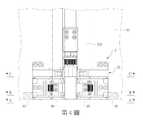
第5圖係為第4圖之A-A’剖面圖。Figure 5 is a cross-sectional view taken along line A-A' of Figure 4.
第6圖係為第4圖之B-B’剖面圖。Figure 6 is a cross-sectional view taken along the line B-B' of Figure 4.
第7圖係為第4圖之C-C’剖面圖。Figure 7 is a C-C' cross-sectional view of Figure 4.
第8圖係為第7圖之本發明在彎摺之後的剖面圖。Figure 8 is a cross-sectional view of the invention of Figure 7 after bending.
第9圖係為第5圖之本發明在彎摺之後的剖面圖。FIG. 9 is a cross-sectional view of the invention of FIG. 5 after bending.
第10圖係為第6圖之本發明在彎摺之後的剖面圖。FIG. 10 is a cross-sectional view of the invention of FIG. 6 after bending.
第11圖係為本發明轉軸模組之較佳實施例在彎摺之後的立體外觀示意圖。FIG. 11 is a schematic perspective view of the preferred embodiment of the hinge module of the present invention after bending.
請參閱第1圖所示,本發明折疊式裝置的轉軸模組1之一端面同時連接一撓性顯示器93之兩半部,轉軸模組1之另一端面分別連接一第一殼體91及一第二殼體92,供連動第一殼體91及第二殼體92,使第一殼體91及第二殼體92相對翻轉;藉以使撓性顯示器93能相對翻轉彎摺或展平,並在整體彎摺時,能如第8圖所示,在第一殼體91及第二殼體92之交接位置讓出一容置空間94,以容納撓性顯示器93之彎曲狀中間部位。As shown in FIG. 1, one end face of the
如第2圖所示,其為本發明折疊式裝置的轉軸模組1之較佳實施例,係包括一基座2、一第一滑移機構3及一第二滑移機構4,其中,基座2位於第一殼體91及第二殼體92之間,基座2之一端具有一第一樞接孔21及一第二樞接孔22,基座2之另一端具有與第一樞接孔21及第二樞接孔22反向之二個樞接孔,基座2之兩側邊分別具有一階級部23。第一滑移機構3樞接第一樞接孔21及第二樞接孔22,第二滑移機構4樞接另外二個樞接孔,藉以使第一滑移機構3與第二滑移機構4相對稱設置於基座2之兩端。另,第一滑移機構3具有一第一齒輪31,第二滑移機構4具有一第二齒輪41,這兩個齒輪可以相互嚙合同動,也可透過第二齒輪41經由一組中間齒輪411(例如正齒輪組、螺旋齒輪組、傘/冠齒輪組)以齒合第一齒輪31,讓第二滑移機構4與第一滑移機構3相對翻轉。而在本實施例中,第一滑移機構3與第二滑移機構4具有相同之結構,謹以第一滑移機構3為例提出以下說明。As shown in FIG. 2, it is a preferred embodiment of the
如第3~7圖所示,該第一滑移機構3包括一第一滑蓋32、一支撐件33、一左四連桿機構34、一右四連桿機構35以及一擺動件36。第一滑蓋32包括一第一蓋體321及一第一滑塊322,第一蓋體321連接第一殼體91,第一滑塊322連接於第一蓋體321之一側,第一滑塊322具有一限位空間323,限位空間323包括相互連通之一限位槽324及一弧形導槽325,限位槽324內具有一壓縮彈簧,該壓縮彈簧做為彈性件326;第一蓋體321之兩端分別為立板,其中一端立板上具有一第二導軌327及一橫向貫穿槽,該橫向貫穿槽做為第二限位部328;第一蓋體321另一端立板上具有一第一導軌329及與第二限位部328同軸之另一橫向貫穿槽,該另一橫向貫穿槽做為第一限位部320,第一導軌329平行第二導軌327。As shown in FIGS. 3-7, the first sliding
該支撐件33係為與第一滑塊322厚度概略相同之板體,支撐件33具有一第一弧形結構331,第一弧形結構331對應容納於第一滑塊322的弧形導槽325之中,藉以讓第一弧形結構331相對於弧形導槽325進行弧形滑動;第一弧形結構331之一端連結一長板,該長板做為支撐部332;第一弧形結構331之另一端具有一勾部333,勾部333伸入限位槽324內以抵壓限制彈性件326。The supporting
該左四連桿機構34係包括一第一連動件341、一第二連動件342及一第三連動件343。其中,第一連動件341係為長條形板體,第一連動件341之一端以一第一樞軸3411樞接基座2之第一樞接孔21,第一連動件341另一端之板面上具有一第一弧形軌道3412。第二連動件342係為長條形板塊,第二連動件342之一端以一第二樞軸3421樞接基座2之第二樞接孔22,第二連動件342之另一端以一第三樞軸3422樞接第三連動件343之一端,第三連動件343之另一端以一第四樞軸3431樞接第一連動件341之另一端,第四樞軸3431再穿過第一滑蓋32之第一導軌329,以於第一導軌329內移動,第三連動件343具有與第四樞軸3431同軸之數個齒,該數個齒做為第二齒合部3432;其中第一及第二樞軸也可以設在基座,第一及第二樞接孔也可以分別設在第一連動件及第二連動件,而這三個連動件之間的樞接處也不限於以樞軸實施,採用相互對應的凹凸結構也具有等同功效。The fourth
該右四連桿機構35包括一第一連動桿351及一第二連動桿352,第一連動桿351之一端以一第六樞軸3511樞接第一樞接孔21,第六樞軸3511同軸連接第一齒輪31,第一連動桿351另一端之板面上具有一第二弧形軌道3512。第二連動桿352之一端以一第七樞軸3521樞接第二樞接孔22,第二連動桿352之另一端以一第八樞軸3522樞接第三連動件343之一端,第三連動件343之另一端以一第九樞軸3433樞接第一連動桿351之另一端,第九樞軸3433與第四樞軸3431同軸,且第九樞軸3433再穿過第一滑蓋32之第二導軌327,以於第二導軌327內移動;其中第一及第二樞軸也可以設在基座,第一及第二樞接孔也可以分別設在第一連動桿及第二連動桿,而且這兩個連動桿分別與基座、第三連動件之間的樞接處也不限於以樞軸實施,採用相互對應的凹凸結構也具有等同功效。The right four
該第一連動件341係進一步以一連接塊37連接一第一殼罩95,提供空間及保護該左四連桿機構3及擺動件36的動作,也能使該第一連動桿351及該第一連動件341係進一步共同以該連接塊37連接該第一殼罩95,提供空間及同時保護該左四連桿機構34、右四連桿機構35及擺動件36的動作,藉以在該第一滑移機構3及該基座2相對旋轉而使左、右四連桿機構34,35作動時,同步使該第一殼罩95與該第一殼體91形成相對滑移;同理可證,該第二滑移機構4也透過其所包含的第一連動桿及該第一連動件,係進一步共同以該連接塊37連接該第二殼罩96,提供空間及同時保護該第二滑移機構42的左、右四連桿機構及擺動件的動作,藉以在該第二滑移機構4及該基座2相對旋轉而使第二滑移機構4的左、右四連桿機構作動時,同步使該第二殼罩96與該第二殼體92形成相對滑移。The
而該擺動件36之一端係具有一第一撥桿361及一第五樞軸362,第一撥桿361穿過第一連動件341的第一弧形軌道3412之後,再插入連接第一滑蓋32之第一限位部320,第五樞軸362樞接第一連動件341,使第一撥桿361以第五樞軸362為旋轉中心而沿著第一弧形軌道3412移動,又因第五樞軸362再穿過第一導軌329,會在第一撥桿361推動第一滑蓋32時,以於第一導軌329內移動。擺動件36之另一端具有一第二撥桿363及一第N樞軸364,第二撥桿363與第一撥桿361同軸,第二撥桿363穿過第一連動桿351的第二弧形軌道3512之後,再插入連接第一滑蓋32之第二限位部328;第N樞軸364與第五樞軸362同軸,第N樞軸364樞接第一連動桿351,使第二撥桿363以第N樞軸364為旋轉中心而沿著第二弧形軌道3512移動,又因第N樞軸364再穿過第二導軌327,會在第二撥桿363推動第一滑蓋32時,以於第二導軌327內移動。另,擺動件36之中間位置具有與第五樞軸362、第N樞軸364同軸之一第一齒合部365,第一齒合部365齒合第二齒合部3432,藉以讓擺動件36與第三連動件343同步轉動,並透過擺動件36同步沿著第一連動件341之第一弧形軌道3412及/或第一連動桿351之第二弧形軌道3512行進,如此即形成行程路徑與長度的補償轉換,而由於擺動件36兩端之第一撥桿361及第二撥桿363同時各自壓迫第一限位部320及第二限位部328,進而能夠一起推壓第一滑蓋32來形成穩定地連動效果,並使第一滑蓋32在翻轉的過程中還能同步進行直線滑移動作。And one end of the swinging
藉此,經由基座2兩側邊之階級部23,即可限制支撐部332之作動,以向上支撐該撓性顯示器93,並讓第一殼體91與第二殼體92呈現在展平狀態,此時,第一滑移機構3及第二滑移機構4之彈性件326分別為被壓縮以蓄積彈力。而如第8~11圖所示,當第一殼體91與第二殼體92相對翻轉時,經由二組左四連桿機構34及右四連桿機構35的同時作動,即可讓二個擺動件36轉動,同時帶動二個第一滑蓋移動32及二個支撐件33,而在二個第一滑蓋32反向移動之後,則可讓二個支撐部332分別脫離基座2兩側邊階級部23之限制,再經由二個彈性件326之彈力回復作用,讓兩個支撐件33產生類似蹺蹺板的作用,而使兩個支撐部332相對偏移一角度,形成容置空間94以容納撓性顯示器93之彎曲狀中間部位。Thereby, through the
因此,本發明具有以下之優點:Therefore, the present invention has the following advantages:
1、本發明在整體折疊過程中,係經由四連桿機構、齒輪組及撥桿以連續推動滑蓋及殼體使產生位移,並在位移及轉動時形成行程路徑與長度的補償轉換,以補償撓性顯示器之彎折部位所形成的曲率半徑與兩殼體間的曲率半徑之間的差異,同時帶動二個支撐部反向偏移以容納撓性顯示器之中間彎曲部位,因此,能有效縮減第一殼體與第二殼體之間於閉合時的間距,以縮小整體體積使有利於設計,達到整體體積薄型化之市場需求,並在整體厚度縮減後的結構體中,能形成穩定的傳動效果。1. In the overall folding process of the present invention, the sliding cover and the housing are continuously pushed through the four-link mechanism, gear set and dial lever to cause displacement, and the travel path and length are formed during the displacement and rotationCompensation conversion, to compensate for the difference between the radius of curvature formed by the bending part of the flexible display and the curvature radius between the two casings, and at the same time drive the two support parts to reversely offset to accommodate the middle bending part of the flexible display Therefore, it can effectively reduce the gap between the first and second shells when closed, to reduce the overall volume to facilitate design, to meet the market demand for thinner overall volume, and to reduce the overall thickness of the structure Medium, can form a stable transmission effect.
2、本發明之支撐件可以在整體彎摺及展平時,產生類似蹺蹺板的自由擺動作用,而無需如習用技術一般的以實體軸樞接,因此,在整體彎摺時,能讓出容置空間以容納撓性顯示器之彎曲狀中間部位,而在整體展平時,又能對撓性顯示器之展平狀中間部位形成穩定之支撐。2. The support member of the present invention can produce a free swinging action similar to a seesaw when the whole is bent and flattened, without the need to pivot with a solid axis as in the conventional technology, therefore, when the whole is bent, it can be accommodated The space can accommodate the curved middle part of the flexible display, and when the whole is flattened, it can form a stable support for the flat middle part of the flexible display.
本發明雖為實現上述目的而揭露了較佳的具體實施例,惟其並非用以限制本發明之構造特徵,任何該技術領域之通常知識者應知,在本發明的技術精神下,任何輕易思及之變化或修飾皆是可能的,且皆為本發明之申請專利範圍所涵蓋。Although the present invention discloses preferred specific embodiments for achieving the above purpose, it is not intended to limit the structural features of the present invention. Any person of ordinary knowledge in the technical field should know that, under the technical spirit of the present invention, any Changes and modifications are possible, and are covered by the patent application scope of the invention.
1:折疊式裝置的轉軸模組1: hinge module of folding device
2:基座2: base
21:第一樞接孔21: The first pivot hole
22:第二樞接孔22: Second pivot hole
23:階級部23: Class Department
3:第一滑移機構3: The first sliding mechanism
31:第一齒輪31: First gear
4:第二滑移機構4: Second sliding mechanism
41:第二齒輪41: Second gear
411:中間齒輪411: intermediate gear
Claims (17)
Translated fromChinesePriority Applications (3)
| Application Number | Priority Date | Filing Date | Title |
|---|---|---|---|
| TW107134205ATWI687795B (en) | 2018-09-27 | 2018-09-27 | A hinge module for the foldable type device |
| CN201811176602.7ACN109469680B (en) | 2018-09-27 | 2018-10-10 | Swivel Module for Folding Units |
| US16/405,768US10761573B2 (en) | 2018-09-27 | 2019-05-07 | Hinge module for a foldable type device |
Applications Claiming Priority (1)
| Application Number | Priority Date | Filing Date | Title |
|---|---|---|---|
| TW107134205ATWI687795B (en) | 2018-09-27 | 2018-09-27 | A hinge module for the foldable type device |
Publications (2)
| Publication Number | Publication Date |
|---|---|
| TW201921219A TW201921219A (en) | 2019-06-01 |
| TWI687795Btrue TWI687795B (en) | 2020-03-11 |
Family
ID=65663337
Family Applications (1)
| Application Number | Title | Priority Date | Filing Date |
|---|---|---|---|
| TW107134205ATWI687795B (en) | 2018-09-27 | 2018-09-27 | A hinge module for the foldable type device |
Country Status (3)
| Country | Link |
|---|---|
| US (1) | US10761573B2 (en) |
| CN (1) | CN109469680B (en) |
| TW (1) | TWI687795B (en) |
Cited By (3)
| Publication number | Priority date | Publication date | Assignee | Title |
|---|---|---|---|---|
| TWI766641B (en)* | 2021-04-09 | 2022-06-01 | 富世達股份有限公司 | Double axis hinge |
| TWI786551B (en)* | 2021-02-25 | 2022-12-11 | 仁寶電腦工業股份有限公司 | Display device |
| TWI810888B (en)* | 2022-04-12 | 2023-08-01 | 連鋐科技股份有限公司 | Pivot device capable of accommodating curved and flexible display panel and its support mechanism |
Families Citing this family (127)
| Publication number | Priority date | Publication date | Assignee | Title |
|---|---|---|---|---|
| CN112005187B (en)* | 2018-08-31 | 2024-09-17 | 惠普发展公司,有限责任合伙企业 | Suspension for display |
| KR102556654B1 (en)* | 2018-12-14 | 2023-07-19 | 삼성전자주식회사 | Electronic device including flexible display and hinge structure |
| TWI709025B (en)* | 2018-12-25 | 2020-11-01 | 仁寶電腦工業股份有限公司 | Electronic device |
| TWI791137B (en)* | 2019-01-18 | 2023-02-01 | 仁寶電腦工業股份有限公司 | Electronic device |
| KR102577249B1 (en)* | 2019-01-21 | 2023-09-12 | 삼성전자주식회사 | Electronic device including magnet and magnetic shielding member |
| TWI710308B (en)* | 2019-02-16 | 2020-11-11 | 兆利科技工業股份有限公司 | A hinge module for the foldable type device |
| CN111692196B (en)* | 2019-03-15 | 2021-10-22 | 华为技术有限公司 | A rotating shaft mechanism and mobile terminal |
| CN111726436B (en)* | 2019-03-23 | 2025-01-24 | 罗天珍 | Dual-synchronous axis lever card-type folding screen mobile phone |
| CN111734731B (en)* | 2019-03-25 | 2021-08-24 | 兆利科技工业股份有限公司 | Swivel Module for Folding Units |
| WO2021007750A1 (en)* | 2019-07-15 | 2021-01-21 | 深圳市柔宇科技有限公司 | Folding device and electronic apparatus |
| CN111833725A (en)* | 2019-04-18 | 2020-10-27 | 深圳市柔宇科技有限公司 | Folding device and electronic equipment |
| CN111866223B (en)* | 2019-04-25 | 2021-06-01 | Oppo广东移动通信有限公司 | Folding machine shell and electronic device |
| CN111862798B (en)* | 2019-04-25 | 2021-06-15 | Oppo广东移动通信有限公司 | Flexible display device and electronic device |
| CN110005695B (en)* | 2019-04-26 | 2023-11-28 | 深圳市富世达通讯有限公司 | Bendable support frame |
| KR102375556B1 (en)* | 2019-04-30 | 2022-03-17 | 삼성전자주식회사 | Structure of Hinge and electronic device including the same |
| CN109949707B (en)* | 2019-05-06 | 2021-05-07 | 惠州Tcl移动通信有限公司 | Foldable display device |
| KR102765038B1 (en)* | 2019-05-07 | 2025-02-12 | 삼성디스플레이 주식회사 | Display panel and method of manufacturing the same |
| TWI730758B (en)* | 2019-05-21 | 2021-06-11 | 仁寶電腦工業股份有限公司 | Seamless hinge and electronic deivce having the same |
| CN111984060B (en)* | 2019-05-22 | 2022-02-01 | 兆利科技工业股份有限公司 | Folding length difference compensation mechanism of multi-folding device |
| KR102709937B1 (en)* | 2019-05-23 | 2024-09-26 | 삼성디스플레이 주식회사 | Foldable display device |
| CN112081814B (en)* | 2019-06-12 | 2021-06-15 | 仁宝电脑工业股份有限公司 | Double-rotating-shaft module and folding electronic device |
| CN110176186B (en)* | 2019-06-14 | 2021-05-25 | 深圳市长盈精密技术股份有限公司 | Balanced control mechanism, folding display device and communication equipment |
| CN110310571B (en)* | 2019-06-18 | 2024-08-06 | 东莞市环力智能科技有限公司 | Flexible screen with inner folding rotating shaft |
| CN112153178A (en) | 2019-06-27 | 2020-12-29 | 华为技术有限公司 | Rotating shaft mechanism and foldable mobile terminal |
| TWI728801B (en)* | 2019-06-27 | 2021-05-21 | 兆利科技工業股份有限公司 | A hinge module and a foldable type device with the same |
| US11353931B2 (en)* | 2019-06-27 | 2022-06-07 | Jarlly Tec Co., Ltd. | Hinge device for a foldable device |
| JP6868064B2 (en)* | 2019-07-12 | 2021-05-12 | レノボ・シンガポール・プライベート・リミテッド | Portable information equipment |
| CN110594279B (en)* | 2019-08-26 | 2024-04-30 | 深圳市长盈精密技术股份有限公司 | Pitch-changing device and folding display device |
| CN110675746B (en)* | 2019-08-26 | 2021-07-02 | 深圳市长盈精密技术股份有限公司 | Folding display device and folding mobile phone |
| CN110599907A (en)* | 2019-09-05 | 2019-12-20 | 武汉华星光电半导体显示技术有限公司 | Foldable display device |
| KR20210048022A (en)* | 2019-10-22 | 2021-05-03 | 삼성디스플레이 주식회사 | Foldable display device and hinge device for the same |
| CN110735848B (en)* | 2019-11-13 | 2024-11-15 | 东莞市劲丰电子有限公司 | Two-axis cross-link outward folding synchronous rotation mechanism |
| CN110873117B (en)* | 2019-11-22 | 2024-11-15 | 东莞市劲丰电子有限公司 | U-shaped inward folding synchronous rotation mechanism with 180-degree support |
| KR102668216B1 (en)* | 2019-12-02 | 2024-05-23 | 삼성전자주식회사 | Foldable electronic device including hinge assembly |
| US11044825B1 (en)* | 2019-12-18 | 2021-06-22 | Wuhan China Star Optoelectronics Semiconductor Display Technology Co., Ltd. | Foldable display device |
| CN111010829B (en)* | 2019-12-26 | 2021-03-16 | 维沃移动通信有限公司 | Electronic device |
| CN111140590B (en)* | 2019-12-27 | 2021-04-13 | 北京空间飞行器总体设计部 | A highly integrated two-point locking hinge |
| CN111120501B (en)* | 2020-01-09 | 2024-11-15 | 东莞市劲丰电子有限公司 | Pop-up teardrop-shaped inward folding synchronous rotation mechanism |
| TWI727637B (en)* | 2020-01-31 | 2021-05-11 | 友達光電股份有限公司 | Bendable display device |
| KR102183555B1 (en)* | 2020-02-05 | 2020-11-26 | 노란 | Foldable structure for flexible display panel |
| CN113280033B (en)* | 2020-02-20 | 2022-07-29 | 北京小米移动软件有限公司 | Hinge, hinge assembly and folding electronic device |
| US20230103700A1 (en)* | 2020-03-17 | 2023-04-06 | Auflex Co., Ltd. | Hinge structure for in-folding type display device |
| CN111399593B (en)* | 2020-03-19 | 2022-03-29 | Oppo广东移动通信有限公司 | Folding assembly and electronic equipment |
| US11202382B2 (en)* | 2020-04-09 | 2021-12-14 | Wuhan China Star Optoelectronics Semiconductor Display Technology Co., Ltd. | Display device |
| CN113534890B (en)* | 2020-04-15 | 2024-06-11 | 华为技术有限公司 | Folding mechanism and terminal |
| CN113542456B (en)* | 2020-04-15 | 2022-09-23 | 华为技术有限公司 | Folding device and electronic equipment |
| CN111614806B (en)* | 2020-04-15 | 2021-04-09 | 华为技术有限公司 | Folding device and electronic equipment |
| CN113542457B (en)* | 2020-04-15 | 2022-10-11 | 华为技术有限公司 | Folding devices and electronic equipment |
| TWI770921B (en)* | 2020-04-16 | 2022-07-11 | 仁寶電腦工業股份有限公司 | Pivot structure and electronic deivce having the same |
| US11599155B2 (en)* | 2020-04-21 | 2023-03-07 | Microsoft Technology Licensing, Llc | Hinged device |
| US11435785B2 (en)* | 2020-04-22 | 2022-09-06 | Eum, Inc. | Foldable display device |
| CN115059684B (en)* | 2020-04-30 | 2024-05-10 | Oppo广东移动通信有限公司 | Spindle suite and electronic equipment |
| CN114962433B (en) | 2020-04-30 | 2023-03-31 | Oppo广东移动通信有限公司 | Electronic component and electronic device |
| CN213270695U (en)* | 2020-05-12 | 2021-05-25 | 杭州安费诺飞凤通信部品有限公司 | Be applied to motion at infolding flexible screen terminal |
| CN111609029B (en)* | 2020-05-22 | 2021-05-04 | 深圳市柔宇科技有限公司 | Folding device and flexible electronic equipment |
| CN111552353B (en)* | 2020-06-08 | 2024-11-15 | 东莞市劲丰电子有限公司 | Arc inward folding rotation mechanism for large-size flexible screen applications |
| CN111601484B (en)* | 2020-06-11 | 2021-08-27 | Oppo广东移动通信有限公司 | Synchronizer, foldable shell assembly and foldable electronic equipment |
| CN113805646B (en)* | 2020-06-15 | 2024-01-30 | 华为技术有限公司 | Folding devices and electronic equipment |
| KR102816913B1 (en)* | 2020-07-10 | 2025-06-10 | 삼성전자주식회사 | Electronic device including flexible display |
| US11181942B1 (en)* | 2020-07-22 | 2021-11-23 | Wuhan China Star Optoelectronics Semiconductor Display Technology Co., Ltd. | Foldable display device |
| KR20220013212A (en) | 2020-07-24 | 2022-02-04 | 삼성전자주식회사 | Hinge structure and electronic device including the same |
| CN114067674A (en)* | 2020-08-06 | 2022-02-18 | 深圳市柔宇科技股份有限公司 | Bendable supporting mechanism and flexible display device |
| US11615720B2 (en) | 2020-08-26 | 2023-03-28 | Samsung Display Co., Ltd. | Display device |
| KR102843631B1 (en)* | 2020-08-28 | 2025-08-08 | 삼성전자주식회사 | Electronic device including flexible display |
| CN111882996B (en)* | 2020-09-09 | 2025-03-18 | 京东方科技集团股份有限公司 | Foldable display device and electronic device |
| KR102849762B1 (en)* | 2020-09-14 | 2025-08-26 | 삼성전자주식회사 | Structure of Link Hinge and electronic device including the same |
| CN112901643B (en)* | 2020-09-14 | 2022-05-24 | 华为技术有限公司 | Folding devices and electronic equipment |
| CN112049861B (en)* | 2020-09-17 | 2024-06-04 | 东莞市劲丰电子有限公司 | Arc inner turning mechanism |
| CN114203028A (en)* | 2020-09-18 | 2022-03-18 | 深圳市柔宇科技股份有限公司 | Foldable structure and electronic equipment |
| KR102299989B1 (en)* | 2020-10-16 | 2021-09-08 | 이경희 | Foldable Hinge Structure for Flexible Display Panel |
| TWI746217B (en)* | 2020-10-20 | 2021-11-11 | 宏碁股份有限公司 | Hinge structure for flexible display and portable electronic device |
| CN115314576B (en)* | 2020-10-29 | 2023-08-04 | 华为技术有限公司 | Housing device and electronic equipment |
| JP7668516B2 (en)* | 2020-10-29 | 2025-04-25 | 株式会社ナチュラレーザ・ワン | Multi-axis hinge device and electronic device using the multi-axis hinge device |
| CN114449072B (en)* | 2020-10-31 | 2023-03-28 | 华为技术有限公司 | Folding mechanism and electronic equipment |
| TWI768530B (en)* | 2020-11-04 | 2022-06-21 | 富世達股份有限公司 | Hinge |
| CN112253611A (en)* | 2020-11-07 | 2021-01-22 | 东莞市劲丰电子有限公司 | Double-connecting-rod rotary U-shaped inward-folding rotary mechanism |
| CN112324795B (en)* | 2020-11-07 | 2024-06-04 | 东莞市劲丰电子有限公司 | U-shaped inner turning mechanism with curved slot |
| CN114576258B (en)* | 2020-12-02 | 2023-07-25 | 昆山科森科技股份有限公司 | Connecting rod type outward folding flexible screen rotating shaft mechanism |
| EP4175265B1 (en)* | 2020-12-28 | 2025-08-06 | Samsung Electronics Co., Ltd. | Hinge structure and foldable electronic device comprising same |
| KR102863277B1 (en)* | 2021-01-05 | 2025-09-24 | 삼성전자주식회사 | Electronic device including hinge structure |
| JP7364774B2 (en)* | 2021-01-05 | 2023-10-18 | サムスン エレクトロニクス カンパニー リミテッド | Electronic devices containing hinge structures |
| KR102863276B1 (en)* | 2021-01-12 | 2025-09-24 | 삼성전자주식회사 | Hinge Structure using a actuator and Foldable Electronic Device having the same |
| CN112908161B (en)* | 2021-01-20 | 2023-07-21 | 成都拓米电子装备制造有限公司 | Folding equipment with good protection effect on screen |
| US11385687B1 (en) | 2021-01-29 | 2022-07-12 | Samsung Electronics Co., Ltd. | Hinge structure and electronic device including the same |
| US11889007B2 (en) | 2021-01-29 | 2024-01-30 | Samsung Electronics Co., Ltd. | Hinge structure and electronic device including the same |
| CN114810800B (en)* | 2021-01-29 | 2024-08-09 | 三星电子株式会社 | Hinge structure and electronic device including the hinge structure |
| CN112682670A (en)* | 2021-02-02 | 2021-04-20 | 维沃移动通信有限公司 | Electronic device |
| CN214507124U (en) | 2021-02-08 | 2021-10-26 | 杭州安费诺飞凤通信部品有限公司 | Hinge and flexible screen mobile terminal of infolding |
| CN214507123U (en) | 2021-02-08 | 2021-10-26 | 杭州安费诺飞凤通信部品有限公司 | Novel hinge and flexible screen mobile terminal of infolding |
| KR102643878B1 (en)* | 2021-03-18 | 2024-03-08 | 주식회사 파인엠텍 | Hinge device for a portable terminal with a foldable structure |
| CN113067923B (en)* | 2021-03-19 | 2023-11-14 | 维沃移动通信有限公司 | Folding mechanism and electronic equipment |
| CN113067924B (en)* | 2021-03-19 | 2023-05-23 | 维沃移动通信有限公司 | Folding mechanism, support structure and electronic equipment |
| CN115314574B (en)* | 2021-05-08 | 2025-08-26 | 北京小米移动软件有限公司 | Hinge mechanism and folding terminal |
| CN115370655B (en)* | 2021-05-18 | 2024-06-25 | 北京小米移动软件有限公司 | Rotating modules and electronic devices |
| CN113194183B (en)* | 2021-05-21 | 2023-08-22 | 维沃移动通信有限公司 | Folding mechanism and electronic equipment |
| CN114449074B (en)* | 2021-05-27 | 2023-01-03 | 荣耀终端有限公司 | Slewing mechanism, strutting arrangement and electronic equipment |
| US20230014585A1 (en)* | 2021-07-16 | 2023-01-19 | Sinher Technology Inc. | Synchronous opening or closing thin hinge |
| US20230037174A1 (en)* | 2021-07-27 | 2023-02-02 | Tpk Advanced Solutions Inc. | Folding electronic device |
| CN113487974B (en)* | 2021-07-30 | 2022-07-12 | 武汉华星光电技术有限公司 | Folding display device |
| US12019482B2 (en) | 2021-07-30 | 2024-06-25 | Wuhan China Star Optoelectronics Semiconductor Display Technology Co., Ltd. | Flexible display panel, electronic device, and hinge |
| CN113314036B (en)* | 2021-07-30 | 2022-01-04 | 武汉华星光电半导体显示技术有限公司 | Flexible display panel, electronic device and hinge |
| US12164344B2 (en) | 2021-08-11 | 2024-12-10 | Apple Inc. | Hinges for folding display devices |
| CN115704419B (en)* | 2021-08-12 | 2025-04-22 | 北京小米移动软件有限公司 | Hinge assembly and electronic device |
| KR102579762B1 (en)* | 2021-08-24 | 2023-09-19 | 주식회사 이엠비 | Hinge device of foldable mobile device using flexible display panel |
| KR102505457B1 (en)* | 2021-08-31 | 2023-03-06 | 주식회사 에스코넥 | Foldable display apparatus with hinge device |
| CN117597647A (en)* | 2021-09-01 | 2024-02-23 | 三星电子株式会社 | Electronic device including hinge assembly |
| JP7658030B2 (en)* | 2021-09-07 | 2025-04-07 | グーグル エルエルシー | Foldable portable display device |
| CN115842883B (en)* | 2021-09-18 | 2023-10-24 | 荣耀终端有限公司 | Folding component of electronic equipment and electronic equipment |
| TWI784728B (en)* | 2021-09-24 | 2022-11-21 | 宏碁股份有限公司 | Foldable electronic device |
| JP2024534295A (en)* | 2021-09-27 | 2024-09-20 | 京東方科技集團股▲ふん▼有限公司 | Pivotable support device and display device |
| CN115995181B (en)* | 2021-10-19 | 2025-08-29 | 华为技术有限公司 | Foldable electronic device, hinge assembly, and housing device |
| CN114017436B (en)* | 2021-10-26 | 2023-06-27 | 武汉华星光电技术有限公司 | Hinge, flexible display panel and electronic device |
| US12368796B2 (en)* | 2021-11-12 | 2025-07-22 | Samsung Electronics Co., Ltd. | Accessory and electronic device including the same |
| CN114078390B (en) | 2021-11-15 | 2023-02-28 | 武汉华星光电半导体显示技术有限公司 | Folding display device |
| CN116168602A (en)* | 2021-11-24 | 2023-05-26 | 北京小米移动软件有限公司 | Connection device and terminal equipment |
| CN114283695A (en)* | 2022-01-29 | 2022-04-05 | Oppo广东移动通信有限公司 | foldable electronic device |
| CN116557406A (en)* | 2022-01-30 | 2023-08-08 | 华为技术有限公司 | A kind of rotating shaft mechanism and electronic equipment |
| CN116696925B (en)* | 2022-02-25 | 2025-05-30 | 富世达股份有限公司 | Synchronous module of hinge |
| CN116781807A (en)* | 2022-03-07 | 2023-09-19 | 北京小米移动软件有限公司 | Hinge, display module assembly and electronic equipment |
| CN114576525B (en)* | 2022-03-31 | 2023-07-21 | 联想(北京)有限公司 | Rotary connection structure and electronic equipment |
| CN116928201A (en)* | 2022-03-31 | 2023-10-24 | 北京小米移动软件有限公司 | Rotating shaft device and folding electronic equipment |
| CN114658753B (en)* | 2022-04-15 | 2023-02-03 | 维沃移动通信有限公司 | Hinge mechanism and electronic device |
| CN114726940B (en)* | 2022-06-06 | 2022-09-09 | 东莞市劲丰电子有限公司 | Lateral movement type bending hinge of flexible screen folding mobile phone |
| US11809240B1 (en)* | 2022-06-21 | 2023-11-07 | Guangdong Zhongqiang Elite Electronic Technology Co., Ltd. | Overturning and supporting rotating shaft for tablet computer |
| CN115234572B (en)* | 2022-07-22 | 2023-07-25 | 武汉华星光电半导体显示技术有限公司 | Hinge device and flexible display panel |
| CN117780769A (en)* | 2022-09-20 | 2024-03-29 | 荣耀终端有限公司 | Rotating mechanisms and foldable electronics |
| CN119860400A (en)* | 2023-10-19 | 2025-04-22 | 华为技术有限公司 | Hinge device, folding device and foldable electronic equipment |
Citations (3)
| Publication number | Priority date | Publication date | Assignee | Title |
|---|---|---|---|---|
| WO2016163852A1 (en)* | 2015-04-09 | 2016-10-13 | 삼성전자 주식회사 | Foldable device |
| CN106255935A (en)* | 2015-04-09 | 2016-12-21 | 三星电子株式会社 | folding device |
| CN107632662A (en)* | 2016-07-19 | 2018-01-26 | 联想(新加坡)私人有限公司 | Portable information device |
Family Cites Families (14)
| Publication number | Priority date | Publication date | Assignee | Title |
|---|---|---|---|---|
| EP3826278B1 (en) | 2011-07-11 | 2024-06-12 | Samsung Electronics Co., Ltd. | Flexible display with guided plates to support the display in the open position |
| US8971031B2 (en) | 2012-08-07 | 2015-03-03 | Creator Technology B.V. | Display system with a flexible display |
| US8804349B2 (en)* | 2012-10-19 | 2014-08-12 | Samsung Display Co., Ltd. | Foldable display device |
| KR101875855B1 (en)* | 2014-02-17 | 2018-07-06 | 삼성전자주식회사 | Hinge apparatus and foldable display apparatus having the same |
| KR102235171B1 (en)* | 2014-09-01 | 2021-04-02 | 엘지디스플레이 주식회사 | Foldable display apparatus |
| KR102233119B1 (en)* | 2014-09-23 | 2021-03-30 | 삼성디스플레이 주식회사 | Display device |
| KR102370015B1 (en)* | 2014-11-25 | 2022-03-07 | 삼성디스플레이 주식회사 | Display apparatus |
| KR102322377B1 (en) | 2014-12-31 | 2021-11-05 | 엘지디스플레이 주식회사 | Foldable display apparatus |
| KR102341879B1 (en) | 2015-01-14 | 2021-12-23 | 삼성디스플레이 주식회사 | Folderable display device |
| KR102421579B1 (en)* | 2015-11-16 | 2022-07-18 | 삼성디스플레이 주식회사 | Foldable display apparatus |
| CN205978043U (en)* | 2016-07-26 | 2017-02-22 | 杭州安费诺飞凤通信部品有限公司 | Hinge and interior flexible screen mobile terminal with flexible screen space in holding |
| US10863641B2 (en)* | 2017-12-04 | 2020-12-08 | Lg Display Co., Ltd. | Foldable display apparatus |
| KR102085235B1 (en)* | 2018-05-28 | 2020-03-05 | (주) 프렉코 | Foldable Display Device |
| CN110714976A (en)* | 2018-07-13 | 2020-01-21 | Oppo广东移动通信有限公司 | Folding electronic device and control method thereof |
- 2018
- 2018-09-27TWTW107134205Apatent/TWI687795B/enactive
- 2018-10-10CNCN201811176602.7Apatent/CN109469680B/enactiveActive
- 2019
- 2019-05-07USUS16/405,768patent/US10761573B2/enactiveActive
Patent Citations (3)
| Publication number | Priority date | Publication date | Assignee | Title |
|---|---|---|---|---|
| WO2016163852A1 (en)* | 2015-04-09 | 2016-10-13 | 삼성전자 주식회사 | Foldable device |
| CN106255935A (en)* | 2015-04-09 | 2016-12-21 | 三星电子株式会社 | folding device |
| CN107632662A (en)* | 2016-07-19 | 2018-01-26 | 联想(新加坡)私人有限公司 | Portable information device |
Cited By (3)
| Publication number | Priority date | Publication date | Assignee | Title |
|---|---|---|---|---|
| TWI786551B (en)* | 2021-02-25 | 2022-12-11 | 仁寶電腦工業股份有限公司 | Display device |
| TWI766641B (en)* | 2021-04-09 | 2022-06-01 | 富世達股份有限公司 | Double axis hinge |
| TWI810888B (en)* | 2022-04-12 | 2023-08-01 | 連鋐科技股份有限公司 | Pivot device capable of accommodating curved and flexible display panel and its support mechanism |
Also Published As
| Publication number | Publication date |
|---|---|
| TW201921219A (en) | 2019-06-01 |
| CN109469680A (en) | 2019-03-15 |
| US20200103935A1 (en) | 2020-04-02 |
| US10761573B2 (en) | 2020-09-01 |
| CN109469680B (en) | 2020-06-23 |
Similar Documents
| Publication | Publication Date | Title |
|---|---|---|
| TWI687795B (en) | A hinge module for the foldable type device | |
| CN109681521B (en) | Rotating shaft module of folding device | |
| TWI693500B (en) | A hinge module for a foldable type device | |
| TWI728801B (en) | A hinge module and a foldable type device with the same | |
| TWI710308B (en) | A hinge module for the foldable type device | |
| CN109654112B (en) | Rotating shaft module of folding device | |
| TWI679522B (en) | A hinge module for the foldable type device | |
| CN115492841B (en) | Folding device and electronic device | |
| CN110225161B (en) | A mobile phone structure with an outer flexible screen | |
| CN110007715B (en) | Rotating shaft module of folding device | |
| CN109814671B (en) | Display system | |
| CN109654113B (en) | Rotating shaft module of folding device | |
| WO2021068794A1 (en) | Hinge applied to inward-foldable flexible screen terminal and inward-foldable flexible screen terminal | |
| WO2019109858A1 (en) | Hinge for mobile terminal having inwardly bendable flexible screen, and mobile terminal having inwardly bendable flexible screen | |
| TWI693581B (en) | A hinge module for the foldable type device | |
| CN217152623U (en) | An inner folding hinge and terminal device applied to a mobile terminal | |
| CN219587959U (en) | Double-rotating shaft linkage structure | |
| TWI721711B (en) | A foldable type device | |
| CN214533998U (en) | Rotatable hinge mechanism suitable for carrying display screen and mobile terminal | |
| TW201921221A (en) | A hinge module for foldable type devices having a fourth sliding portion at an end of an intermediate transmission member slidably positioned on a second sliding portion of a transmission member to allow the transmission member and a transmission plate to move in opposite directions | |
| CN112112882B (en) | Hidden split hinge | |
| CN114697418A (en) | Limit action mechanism and electronic equipment | |
| TWM643004U (en) | Double shaft linkage structure | |
| CN211239891U (en) | Hinge applied to flexible screen terminal and hinge combination structure of internally-folded flexible screen terminal | |
| TWI866774B (en) | A rotating shaft structure (1) |