TWI686867B - Substrate processing method and substrate processing apparatus - Google Patents
Substrate processing method and substrate processing apparatusDownload PDFInfo
- Publication number
- TWI686867B TWI686867BTW107107149ATW107107149ATWI686867BTW I686867 BTWI686867 BTW I686867BTW 107107149 ATW107107149 ATW 107107149ATW 107107149 ATW107107149 ATW 107107149ATW I686867 BTWI686867 BTW I686867B
- Authority
- TW
- Taiwan
- Prior art keywords
- substrate
- mixed gas
- gas supply
- unit
- space
- Prior art date
Links
- 239000000758substrateSubstances0.000titleclaimsabstractdescription339
- 238000003672processing methodMethods0.000titleclaimsabstractdescription17
- CBENFWSGALASAD-UHFFFAOYSA-NOzoneChemical compound[O-][O+]=OCBENFWSGALASAD-UHFFFAOYSA-N0.000claimsabstractdescription102
- XLYOFNOQVPJJNP-UHFFFAOYSA-NwaterChemical compoundOXLYOFNOQVPJJNP-UHFFFAOYSA-N0.000claimsabstractdescription77
- 238000010438heat treatmentMethods0.000claimsdescription54
- 239000007788liquidSubstances0.000claimsdescription35
- 230000002093peripheral effectEffects0.000claimsdescription24
- 238000000034methodMethods0.000claimsdescription23
- 238000000354decomposition reactionMethods0.000claimsdescription21
- 238000003860storageMethods0.000claimsdescription20
- 230000001678irradiating effectEffects0.000claimsdescription9
- 238000002156mixingMethods0.000claimsdescription5
- 238000000859sublimationMethods0.000claimsdescription3
- 230000008022sublimationEffects0.000claimsdescription3
- 239000000203mixtureSubstances0.000claims1
- 230000005855radiationEffects0.000claims1
- 239000007921spraySubstances0.000claims1
- 239000007789gasSubstances0.000description233
- 238000010586diagramMethods0.000description20
- 230000004048modificationEffects0.000description11
- 238000012986modificationMethods0.000description11
- 230000008569processEffects0.000description11
- 239000001257hydrogenSubstances0.000description10
- 229910052739hydrogenInorganic materials0.000description10
- 230000003647oxidationEffects0.000description10
- 238000007254oxidation reactionMethods0.000description10
- TUJKJAMUKRIRHC-UHFFFAOYSA-NhydroxylChemical compound[OH]TUJKJAMUKRIRHC-UHFFFAOYSA-N0.000description9
- 239000000126substanceSubstances0.000description8
- 239000012530fluidSubstances0.000description6
- 230000001590oxidative effectEffects0.000description5
- 206010040844Skin exfoliationDiseases0.000description4
- 238000001816coolingMethods0.000description4
- 239000010408filmSubstances0.000description4
- 239000007800oxidant agentSubstances0.000description4
- 230000007723transport mechanismEffects0.000description4
- QTBSBXVTEAMEQO-UHFFFAOYSA-NAcetic acidChemical compoundCC(O)=OQTBSBXVTEAMEQO-UHFFFAOYSA-N0.000description3
- MUBZPKHOEPUJKR-UHFFFAOYSA-NOxalic acidChemical compoundOC(=O)C(O)=OMUBZPKHOEPUJKR-UHFFFAOYSA-N0.000description3
- 238000010521absorption reactionMethods0.000description3
- QVGXLLKOCUKJST-UHFFFAOYSA-Natomic oxygenChemical compound[O]QVGXLLKOCUKJST-UHFFFAOYSA-N0.000description3
- 230000015572biosynthetic processEffects0.000description3
- 238000001035dryingMethods0.000description3
- 230000000694effectsEffects0.000description3
- 238000005530etchingMethods0.000description3
- 230000006870functionEffects0.000description3
- 238000005304joiningMethods0.000description3
- 239000001301oxygenSubstances0.000description3
- 229910052760oxygenInorganic materials0.000description3
- 239000010409thin filmSubstances0.000description3
- CURLTUGMZLYLDI-UHFFFAOYSA-NCarbon dioxideChemical compoundO=C=OCURLTUGMZLYLDI-UHFFFAOYSA-N0.000description2
- 230000000903blocking effectEffects0.000description2
- 150000001735carboxylic acidsChemical class0.000description2
- 238000006243chemical reactionMethods0.000description2
- 239000003795chemical substances by applicationSubstances0.000description2
- 238000005401electroluminescenceMethods0.000description2
- 239000003480eluentSubstances0.000description2
- 239000005011phenolic resinSubstances0.000description2
- 238000000206photolithographyMethods0.000description2
- 239000004065semiconductorSubstances0.000description2
- 235000012431wafersNutrition0.000description2
- OKTJSMMVPCPJKN-UHFFFAOYSA-NCarbonChemical compound[C]OKTJSMMVPCPJKN-UHFFFAOYSA-N0.000description1
- YZCKVEUIGOORGS-IGMARMGPSA-NProtiumChemical compound[1H]YZCKVEUIGOORGS-IGMARMGPSA-N0.000description1
- XUIMIQQOPSSXEZ-UHFFFAOYSA-NSiliconChemical compound[Si]XUIMIQQOPSSXEZ-UHFFFAOYSA-N0.000description1
- 230000009471actionEffects0.000description1
- 230000004888barrier functionEffects0.000description1
- 230000005587bubblingEffects0.000description1
- 229910052799carbonInorganic materials0.000description1
- 239000001569carbon dioxideSubstances0.000description1
- 229910002092carbon dioxideInorganic materials0.000description1
- 239000000969carrierSubstances0.000description1
- 239000000919ceramicSubstances0.000description1
- 238000000576coating methodMethods0.000description1
- 238000005260corrosionMethods0.000description1
- 230000007797corrosionEffects0.000description1
- 238000011049fillingMethods0.000description1
- 239000004973liquid crystal related substanceSubstances0.000description1
- 238000011068loading methodMethods0.000description1
- 238000004519manufacturing processMethods0.000description1
- 230000007246mechanismEffects0.000description1
- QSHDDOUJBYECFT-UHFFFAOYSA-NmercuryChemical compound[Hg]QSHDDOUJBYECFT-UHFFFAOYSA-N0.000description1
- 229910052753mercuryInorganic materials0.000description1
- VUZPPFZMUPKLLV-UHFFFAOYSA-Nmethane;hydrateChemical compoundC.OVUZPPFZMUPKLLV-UHFFFAOYSA-N0.000description1
- 230000003287optical effectEffects0.000description1
- 150000002894organic compoundsChemical class0.000description1
- 235000006408oxalic acidNutrition0.000description1
- 238000007789sealingMethods0.000description1
- 229910052710siliconInorganic materials0.000description1
- 239000010703siliconSubstances0.000description1
- 238000009281ultraviolet germicidal irradiationMethods0.000description1
Images


Classifications
- H—ELECTRICITY
- H01—ELECTRIC ELEMENTS
- H01L—SEMICONDUCTOR DEVICES NOT COVERED BY CLASS H10
- H01L21/00—Processes or apparatus adapted for the manufacture or treatment of semiconductor or solid state devices or of parts thereof
- H01L21/02—Manufacture or treatment of semiconductor devices or of parts thereof
- H01L21/027—Making masks on semiconductor bodies for further photolithographic processing not provided for in group H01L21/18 or H01L21/34
- H01L21/0271—Making masks on semiconductor bodies for further photolithographic processing not provided for in group H01L21/18 or H01L21/34 comprising organic layers
- H01L21/0273—Making masks on semiconductor bodies for further photolithographic processing not provided for in group H01L21/18 or H01L21/34 comprising organic layers characterised by the treatment of photoresist layers
- G—PHYSICS
- G03—PHOTOGRAPHY; CINEMATOGRAPHY; ANALOGOUS TECHNIQUES USING WAVES OTHER THAN OPTICAL WAVES; ELECTROGRAPHY; HOLOGRAPHY
- G03F—PHOTOMECHANICAL PRODUCTION OF TEXTURED OR PATTERNED SURFACES, e.g. FOR PRINTING, FOR PROCESSING OF SEMICONDUCTOR DEVICES; MATERIALS THEREFOR; ORIGINALS THEREFOR; APPARATUS SPECIALLY ADAPTED THEREFOR
- G03F7/00—Photomechanical, e.g. photolithographic, production of textured or patterned surfaces, e.g. printing surfaces; Materials therefor, e.g. comprising photoresists; Apparatus specially adapted therefor
- G03F7/20—Exposure; Apparatus therefor
- G03F7/2002—Exposure; Apparatus therefor with visible light or UV light, through an original having an opaque pattern on a transparent support, e.g. film printing, projection printing; by reflection of visible or UV light from an original such as a printed image
- G03F7/2004—Exposure; Apparatus therefor with visible light or UV light, through an original having an opaque pattern on a transparent support, e.g. film printing, projection printing; by reflection of visible or UV light from an original such as a printed image characterised by the use of a particular light source, e.g. fluorescent lamps or deep UV light
- G—PHYSICS
- G03—PHOTOGRAPHY; CINEMATOGRAPHY; ANALOGOUS TECHNIQUES USING WAVES OTHER THAN OPTICAL WAVES; ELECTROGRAPHY; HOLOGRAPHY
- G03F—PHOTOMECHANICAL PRODUCTION OF TEXTURED OR PATTERNED SURFACES, e.g. FOR PRINTING, FOR PROCESSING OF SEMICONDUCTOR DEVICES; MATERIALS THEREFOR; ORIGINALS THEREFOR; APPARATUS SPECIALLY ADAPTED THEREFOR
- G03F7/00—Photomechanical, e.g. photolithographic, production of textured or patterned surfaces, e.g. printing surfaces; Materials therefor, e.g. comprising photoresists; Apparatus specially adapted therefor
- G03F7/26—Processing photosensitive materials; Apparatus therefor
- G03F7/38—Treatment before imagewise removal, e.g. prebaking
- G—PHYSICS
- G03—PHOTOGRAPHY; CINEMATOGRAPHY; ANALOGOUS TECHNIQUES USING WAVES OTHER THAN OPTICAL WAVES; ELECTROGRAPHY; HOLOGRAPHY
- G03F—PHOTOMECHANICAL PRODUCTION OF TEXTURED OR PATTERNED SURFACES, e.g. FOR PRINTING, FOR PROCESSING OF SEMICONDUCTOR DEVICES; MATERIALS THEREFOR; ORIGINALS THEREFOR; APPARATUS SPECIALLY ADAPTED THEREFOR
- G03F7/00—Photomechanical, e.g. photolithographic, production of textured or patterned surfaces, e.g. printing surfaces; Materials therefor, e.g. comprising photoresists; Apparatus specially adapted therefor
- G03F7/26—Processing photosensitive materials; Apparatus therefor
- G03F7/42—Stripping or agents therefor
- H—ELECTRICITY
- H01—ELECTRIC ELEMENTS
- H01L—SEMICONDUCTOR DEVICES NOT COVERED BY CLASS H10
- H01L21/00—Processes or apparatus adapted for the manufacture or treatment of semiconductor or solid state devices or of parts thereof
- H01L21/02—Manufacture or treatment of semiconductor devices or of parts thereof
- H01L21/02104—Forming layers
- H01L21/02107—Forming insulating materials on a substrate
- H01L21/02296—Forming insulating materials on a substrate characterised by the treatment performed before or after the formation of the layer
- H01L21/02299—Forming insulating materials on a substrate characterised by the treatment performed before or after the formation of the layer pre-treatment
- H01L21/02312—Forming insulating materials on a substrate characterised by the treatment performed before or after the formation of the layer pre-treatment treatment by exposure to a gas or vapour
- H—ELECTRICITY
- H01—ELECTRIC ELEMENTS
- H01L—SEMICONDUCTOR DEVICES NOT COVERED BY CLASS H10
- H01L21/00—Processes or apparatus adapted for the manufacture or treatment of semiconductor or solid state devices or of parts thereof
- H01L21/02—Manufacture or treatment of semiconductor devices or of parts thereof
- H01L21/04—Manufacture or treatment of semiconductor devices or of parts thereof the devices having potential barriers, e.g. a PN junction, depletion layer or carrier concentration layer
- H01L21/18—Manufacture or treatment of semiconductor devices or of parts thereof the devices having potential barriers, e.g. a PN junction, depletion layer or carrier concentration layer the devices having semiconductor bodies comprising elements of Group IV of the Periodic Table or AIIIBV compounds with or without impurities, e.g. doping materials
- H01L21/30—Treatment of semiconductor bodies using processes or apparatus not provided for in groups H01L21/20 - H01L21/26
- H01L21/324—Thermal treatment for modifying the properties of semiconductor bodies, e.g. annealing, sintering
- H—ELECTRICITY
- H01—ELECTRIC ELEMENTS
- H01L—SEMICONDUCTOR DEVICES NOT COVERED BY CLASS H10
- H01L21/00—Processes or apparatus adapted for the manufacture or treatment of semiconductor or solid state devices or of parts thereof
- H01L21/67—Apparatus specially adapted for handling semiconductor or electric solid state devices during manufacture or treatment thereof; Apparatus specially adapted for handling wafers during manufacture or treatment of semiconductor or electric solid state devices or components ; Apparatus not specifically provided for elsewhere
- H01L21/67005—Apparatus not specifically provided for elsewhere
- H01L21/67011—Apparatus for manufacture or treatment
- H01L21/67017—Apparatus for fluid treatment
Landscapes
- Engineering & Computer Science (AREA)
- Physics & Mathematics (AREA)
- General Physics & Mathematics (AREA)
- Condensed Matter Physics & Semiconductors (AREA)
- Manufacturing & Machinery (AREA)
- Computer Hardware Design (AREA)
- Microelectronics & Electronic Packaging (AREA)
- Power Engineering (AREA)
- Cleaning Or Drying Semiconductors (AREA)
- Container, Conveyance, Adherence, Positioning, Of Wafer (AREA)
- Exposure Of Semiconductors, Excluding Electron Or Ion Beam Exposure (AREA)
Abstract
Translated fromChineseDescription
Translated fromChinese本發明是有關於一種對基板進行處理的基板處理方法以及基板處理裝置。成為處理對象的基板中,例如包括半導體晶圓、液晶顯示裝置用基板、有機電致發光(Electroluminescence,EL)顯示裝置等平板顯示器(Flat Panel Display,FPD)用基板、光碟用基板、磁碟用基板、光磁碟用基板、光罩用基板、陶瓷基板、太陽電池用基板等基板。The invention relates to a substrate processing method and a substrate processing device for processing a substrate. The substrates to be processed include, for example, semiconductor wafers, substrates for liquid crystal display devices, organic electroluminescence (EL) display devices, flat panel display (FPD) substrates, optical disc substrates, magnetic disc substrates, etc. Substrates such as substrates, substrates for optomagnetic discs, substrates for photomasks, ceramic substrates, substrates for solar cells, etc.
於半導體元件等的製造步驟中,例如進行光微影(photolithography)處理,該光微影處理依序進行於基板上塗佈抗蝕劑液而形成抗蝕劑的抗蝕劑塗佈處理、將該抗蝕劑曝光成既定圖案的曝光處理、及對經曝光的抗蝕劑進行顯影的顯影處理。藉此,於基板上形成既定的抗蝕劑圖案。繼而,將該抗蝕劑圖案作為遮罩(mask),進行基板上的被處理膜的蝕刻處理。然後將抗蝕劑剝離,於基板的表面形成既定的圖案。In the manufacturing steps of semiconductor devices and the like, for example, a photolithography process is performed, and the photolithography process is sequentially performed by applying a resist solution on a substrate to form a resist, a resist coating process is performed This resist is exposed to a predetermined pattern, and a developing process is performed to develop the exposed resist.By this, a predetermined resist pattern is formed on the substrate. Then, using the resist pattern as a mask, etching processing of the film to be processed on the substrate is performed. Then, the resist is peeled off, and a predetermined pattern is formed on the surface of the substrate.
下述專利文獻1中揭示有一種藉由紫外線及臭氧的作用將形成於基板表面的抗蝕劑剝離的方法。詳細而言,該方法中對收容基板的腔室內供給含臭氧氣體(臭氧與氧氣的混合氣體),藉此將腔室內設定為臭氧環境。繼而,於臭氧環境中對基板照射紫外線,由此將臭氧分解。藉此,產生作為氧化力相對較高的活性氧的羥基自由基(OH自由基)等。藉由該羥基自由基而促進利用臭氧的抗蝕劑剝離。The following
[先前技術文獻][Prior Technical Literature]
[專利文獻][Patent Literature]
[專利文獻1]日本專利特開2000-286251號公報[Patent Document 1] Japanese Patent Laid-Open No. 2000-286251
[專利文獻2]美國專利申請公開第2017/252781號說明書[Patent Literature 2] US Patent Application Publication No. 2017/252781
羥基自由基容易因臭氧與氫自由基反應而產生。然而,專利文獻1所記載的方法中,無法對腔室內供給充分的氫自由基。因此,無法充分產生羥基自由基,故有無法充分促進抗蝕劑的剝離之虞。Hydroxyl radicals are easily generated by the reaction of ozone and hydrogen radicals. However, in the method described in
另一方面,於專利文獻2中揭示有一種於在基板表面形成有臭氧水等液體的膜(液膜)的狀態下對基板表面照射紫外線的方法。該方法中,可藉由紫外線而由水產生氫自由基。然而,紫外線被液膜吸收,故無法充分到達基板的表面附近,而有無法於基板的表面附近產生充分的氫自由基之虞。由此,無法於基板的表面附近產生充分的羥基自由基。因此,有無法充分促進抗蝕劑的剝離之虞。On the other hand,
因此,解決該些課題,良好地促進形成於基板表面的抗蝕劑的剝離是需要的。Therefore, it is necessary to solve these problems and promote the peeling of the resist formed on the surface of the substrate.
本發明的一個目的在於提供一種可將形成於基板表面的抗蝕劑良好地去除的基板處理方法以及基板處理裝置。An object of the present invention is to provide a substrate processing method and a substrate processing apparatus that can remove a resist formed on the surface of a substrate satisfactorily.
本發明的一實施形態提供一種基板處理方法,用於自基板的表面去除抗蝕劑,並且所述基板處理方法包括以下步驟:支持步驟,使支持構件水平地支持所述基板;混合氣體供給步驟,對所述基板的表面附近供給水蒸氣與臭氧氣體的混合氣體;以及紫外線照射步驟,對供給於所述基板的表面附近的混合氣體照射紫外線。An embodiment of the present invention provides a substrate processing method for removing a resist from a surface of a substrate, and the substrate processing method includes the following steps: a supporting step that allows the supporting member to horizontally support the substrate; a mixed gas supply step , A mixed gas of water vapor and ozone gas is supplied near the surface of the substrate; and an ultraviolet irradiation step, the mixed gas supplied near the surface of the substrate is irradiated with ultraviolet rays.
根據該方法,將使水蒸氣與臭氧氣體混合而成的混合氣體供給於經水平地支持的基板的表面附近。藉由對混合氣體照射紫外線,而將混合氣體中的水蒸氣分解。藉此,生成氫自由基。因此,藉由使氫自由基與臭氧反應,可於基板的表面附近產生充分量的羥基自由基。According to this method, a mixed gas obtained by mixing water vapor and ozone gas is supplied near the surface of the substrate supported horizontally. By irradiating the mixed gas with ultraviolet rays, the water vapor in the mixed gas is decomposed. This generates hydrogen radicals.Therefore, by reacting hydrogen radicals with ozone, a sufficient amount of hydroxyl radicals can be generated near the surface of the substrate.
進而,由於對基板的表面供給水蒸氣、即氣態水,故可抑制液態水附著於基板的表面。因此,可不受液態水吸收紫外線的妨礙而於基板的表面附近使臭氧分解。Furthermore, since water vapor, that is, gaseous water is supplied to the surface of the substrate, the adhesion of liquid water to the surface of the substrate can be suppressed. Therefore, ozone can be decomposed in the vicinity of the surface of the substrate without being hindered by the absorption of ultraviolet rays by liquid water.
結果,可將形成於基板表面的抗蝕劑良好地去除(剝離)。As a result, the resist formed on the substrate surface can be removed (stripped) well.
於本發明的一實施形態中,所述紫外線照射步驟包括以下步驟:藉由紫外線的照射而於所述基板的表面附近產生羥基自由基的步驟;以及藉由所述羥基自由基將所述抗蝕劑分解的步驟。因此,可利用藉由紫外線照射所產生的羥基自由基而將抗蝕劑可靠地分解。In one embodiment of the present invention, the ultraviolet irradiation step includes the following steps: a step of generating hydroxyl radicals near the surface of the substrate by ultraviolet irradiation; and the hydroxyl radicals Etching agent decomposition steps. Therefore, the hydroxyl radical generated by ultraviolet irradiation can reliably decompose the resist.
於本發明的一實施形態中,所述基板處理方法更包括第一加熱步驟,所述第一加熱步驟加熱所述基板且與所述混合氣體供給步驟同時實行。藉此,可將基板的表面附近的混合氣體加熱。因此,可抑制水蒸氣於基板的表面附近液化。In an embodiment of the present invention, the substrate processing method further includes a first heating step, and the first heating step heats the substrate and is performed simultaneously with the mixed gas supply step. By this, the mixed gas near the surface of the substrate can be heated. Therefore, liquefaction of water vapor near the surface of the substrate can be suppressed.
於本發明的一實施形態中,所述基板處理方法更包括第二加熱步驟,所述第二加熱步驟加熱所述基板且與所述紫外線照射步驟同時實行。藉此,將基板的表面附近所產生的抗蝕劑的分解物加熱。因此,可使抗蝕劑的分解物昇華而成為氣體狀態。故而可抑制抗蝕劑的分解物於基板的表面固化。因此,可將形成於基板表面的抗蝕劑良好地去除。In one embodiment of the present invention, the substrate processing method further includes a second heating step. The second heating step heats the substrate and is performed simultaneously with the ultraviolet irradiation step. By this, the decomposition product of the resist generated near the surface of the substrate is heated. Therefore, the decomposition product of the resist can be sublimated to a gas state. Therefore, curing of the decomposition product of the resist on the surface of the substrate can be suppressed. Therefore, the resist formed on the substrate surface can be removed well.
於本發明的一實施形態中,所述混合氣體供給步驟包括混合氣體噴出步驟,該混合氣體噴出步驟自噴出口向所述基板的表面噴出所述混合氣體。根據該方法,與從各別的噴出口向基板的表面噴出水蒸氣與臭氧氣體的構成相比較,可確保基板表面附近的水蒸氣與臭氧氣體的比例(比率)於基板的整個表面均等。In an embodiment of the present invention, the mixed gas supply step includes a mixed gas ejection step that ejects the mixed gas from the ejection port toward the surface of the substrate. According to this method, compared with the configuration in which water vapor and ozone gas are ejected from the respective ejection ports onto the surface of the substrate, it is possible to ensure that the ratio (ratio) of water vapor to ozone gas near the surface of the substrate is equal to the entire surface of the substrate.
於本發明的一實施形態中,所述基板處理方法更包括以下步驟:空間形成步驟,至少於所述紫外線照射步驟開始之前,形成收容所述基板且與外部阻斷的空間;以及排氣步驟,在所述紫外線照射步驟的實行中,對所述空間內進行排氣。In an embodiment of the invention, the substrate processing method further includes the following steps: a space forming step, at least before the ultraviolet irradiation step starts,Forming a space that houses the substrate and is blocked from the outside; and an exhaust step, during the execution of the ultraviolet irradiation step, exhausts the interior of the space.
藉此,可於對基板的表面附近的混合氣體照射紫外線之前,將基板收容於與外部阻斷的空間內。因此,可於使空間內(基板的表面附近的空間中)充滿混合氣體的狀態下照射紫外線。因此,可產生充分量的羥基自由基。另一方面,於紫外線的照射中,對收容基板的空間進行排氣。藉此,可將抗蝕劑的分解物於在基板的表面固化之前排出至空間的外部。With this, the substrate can be accommodated in a space blocked from the outside before the mixed gas near the surface of the substrate is irradiated with ultraviolet rays. Therefore, ultraviolet rays can be irradiated in a state in which the space (in the space near the surface of the substrate) is filled with the mixed gas. Therefore, a sufficient amount of hydroxyl radicals can be generated. On the other hand, during the irradiation of ultraviolet rays, the space for housing the substrate is exhausted. With this, the decomposition product of the resist can be discharged to the outside of the space before the surface of the substrate is cured.
於本發明的一實施形態中,所述基板處理方法更包括混合氣體形成步驟,該混合氣體形成步驟對儲罐中蓄積的液態水供給所述臭氧氣體,藉此形成所述混合氣體。因此,在準備混合氣體時,無需與臭氧氣體相區別而另準備水蒸氣後將臭氧氣體與水蒸氣混合。即,可簡單地準備混合氣體。In one embodiment of the present invention, the substrate processing method further includes a mixed gas forming step that supplies the ozone gas to the liquid water accumulated in the storage tank, thereby forming the mixed gas. Therefore, when preparing the mixed gas, it is not necessary to distinguish it from the ozone gas, and after preparing another steam, the ozone gas and the steam are mixed. That is, the mixed gas can be easily prepared.
於本發明的一實施形態中,提供一種基板處理裝置,用於自基板的表面去除抗蝕劑,並且所述基板處理裝置含有:支持構件,水平地支持所述基板;混合氣體供給單元,向所述基板的表面供給混合氣體;紫外線照射單元,向所述基板的表面照射紫外線;以及控制器,以實行混合氣體供給步驟及紫外線照射步驟的方式編程,所述混合氣體供給步驟自所述混合氣體供給單元對所述基板的表面附近供給所述混合氣體,所述紫外線照射步驟在將所述混合氣體供給於所述基板的表面附近的狀態下,使所述紫外線照射單元照射紫外線。In one embodiment of the present invention, a substrate processing apparatus for removing resist from a surface of a substrate is provided, and the substrate processing apparatus includes: a supporting member that horizontally supports the substrate; a mixed gas supply unit A mixed gas is supplied to the surface of the substrate; an ultraviolet irradiation unit irradiates ultraviolet light to the surface of the substrate; and a controller is programmed to perform a mixed gas supply step and an ultraviolet irradiation step, the mixed gas supply step is from the mixing The gas supply unit supplies the mixed gas to the vicinity of the surface of the substrate, and in the ultraviolet irradiation step, the ultraviolet irradiation unit is irradiated with ultraviolet rays while the mixed gas is supplied near the surface of the substrate.
根據該構成,對藉由支持構件水平地支持的基板的表面附近供給使水蒸氣與臭氧氣體混合而成的混合氣體。藉由自紫外線照射單元對混合氣體照射紫外線,而將混合氣體中的水蒸氣分解。藉此,生成氫自由基。因此,藉由使氫自由基與臭氧反應,可於基板的表面附近產生充分量的羥基自由基。According to this configuration, a mixed gas obtained by mixing water vapor and ozone gas is supplied to the vicinity of the surface of the substrate horizontally supported by the support member. By irradiating the mixed gas with ultraviolet rays from the ultraviolet irradiation unit, the water vapor in the mixed gas is decomposed. This generates hydrogen radicals. Therefore, by reacting hydrogen radicals with ozone, a sufficient amount of hydroxyl radicals can be generated near the surface of the substrate.
進而,由於對基板的表面供給水蒸氣、即氣態水,故可抑制液態水附著於基板的表面。因此,可不受液態水吸收紫外線的妨礙而於基板的表面附近使臭氧分解。Furthermore, since water vapor, that is, gaseous water is supplied to the surface of the substrate, the adhesion of liquid water to the surface of the substrate can be suppressed. Therefore, ozone can be decomposed in the vicinity of the surface of the substrate without being hindered by the absorption of ultraviolet rays by liquid water.
結果,可將形成於基板表面的抗蝕劑良好地去除。As a result, the resist formed on the substrate surface can be removed well.
於本發明的一實施形態中,所述控制器是以在所述紫外線照射步驟中實行以下步驟的方式編程:藉由紫外線的照射而於所述基板的表面附近產生羥基自由基的步驟;以及藉由所述羥基自由基將抗蝕劑分解的步驟。因此,可利用藉由紫外線照射所產生的羥基自由基而將抗蝕劑可靠地分解。In an embodiment of the present invention, the controller is programmed in the ultraviolet irradiation step by performing the following steps: a step of generating hydroxyl radicals near the surface of the substrate by ultraviolet irradiation; and The step of decomposing the resist by the hydroxyl radical. Therefore, the hydroxyl radical generated by ultraviolet irradiation can reliably decompose the resist.
於本發明的一實施形態中,所述基板處理裝置更含有加熱所述基板的第一基板加熱單元。而且,所述控制器是以實行第一加熱步驟的方式編程,所述第一加熱步驟於所述混合氣體供給步驟的同時,使所述第一基板加熱單元加熱所述基板。因此,可使用第一基板加熱單元將基板的表面附近的混合氣體加熱。因此,可抑制水蒸氣於基板的表面附近液化。In one embodiment of the present invention, the substrate processing apparatus further includes a first substrate heating unit that heats the substrate. Moreover, the controller is programmed in such a manner that a first heating step is performed, and the first heating step causes the first substrate heating unit to heat the substrate at the same time as the mixed gas supply step. Therefore, the mixed gas near the surface of the substrate can be heated using the first substrate heating unit. Therefore, liquefaction of water vapor near the surface of the substrate can be suppressed.
於本發明的一實施形態中,所述基板處理裝置更含有加熱所述基板的第二基板加熱單元。而且,所述控制器是以實行第二加熱步驟的方式編程,所述第二加熱步驟於所述紫外線照射步驟的同時,使所述第二基板加熱單元加熱所述基板。因此,可使用第二基板加熱單元將基板的表面附近所產生的抗蝕劑的分解物加熱。藉此,可使抗蝕劑的分解物昇華而成為氣體狀態。因此,可抑制抗蝕劑的分解物於基板的表面固化。因此,可將形成於基板表面的抗蝕劑良好地去除。In one embodiment of the present invention, the substrate processing apparatus further includes a second substrate heating unit that heats the substrate. Moreover, the controllerProgramming in the manner of two heating steps, the second heating step causes the second substrate heating unit to heat the substrate at the same time as the ultraviolet irradiation step. Therefore, the decomposition product of the resist generated near the surface of the substrate can be heated using the second substrate heating unit. As a result, the decomposition product of the resist can be sublimated into a gas state. Therefore, the decomposition products of the resist can be prevented from curing on the surface of the substrate. Therefore, the resist formed on the substrate surface can be removed well.
於本發明的一實施形態中,所述基板處理裝置更含有:空間形成單元,形成收容所述基板且與外部阻斷的空間;以及排氣單元,對所述空間進行排氣。而且,所述控制器是以進一步實行以下步驟的方式編程:空間形成步驟,至少於所述紫外線照射步驟開始之前,控制所述空間形成單元而形成空間;以及排氣步驟,於所述紫外線照射步驟的實行中,控制所述排氣單元而對所述空間進行排氣。In one embodiment of the present invention, the substrate processing apparatus further includes: a space forming unit that forms a space that houses the substrate and is blocked from the outside; and an exhaust unit that exhausts the space. Moreover, the controller is programmed in such a manner that the following steps are further performed: a space forming step, at least before the ultraviolet irradiation step starts, controlling the space forming unit to form a space; and an exhaust step, under the ultraviolet irradiation During the execution of the step, the exhaust unit is controlled to exhaust the space.
藉此,於對基板的表面附近的混合氣體照射紫外線之前,藉由空間形成單元而形成與外部阻斷的空間,並於該空間中收容基板。因此,可於使空間內(基板的表面附近的空間中)充滿混合氣體的狀態下,自紫外線照射單元照射紫外線。因此,可產生充分量的羥基自由基。另一方面,於紫外線的照射中,藉由排氣單元對收容基板的空間進行排氣。藉此,可將抗蝕劑的分解物於在基板的表面固化之前排出至空間的外部。Thereby, before the ultraviolet gas is irradiated to the mixed gas near the surface of the substrate, a space is formed by the space forming unit to block the outside, and the substrate is accommodated in the space. Therefore, ultraviolet rays can be irradiated from the ultraviolet irradiation unit in a state where the space (the space near the surface of the substrate) is filled with the mixed gas. Therefore, a sufficient amount of hydroxyl radicals can be generated. On the other hand, during the irradiation of ultraviolet rays, the space for housing the substrate is exhausted by the exhaust unit. With this, the decomposition product of the resist can be discharged to the outside of the space before the surface of the substrate is cured.
於本發明的一實施形態中,所述基板處理裝置更含有:儲罐,蓄積液態水;以及臭氧氣體供給單元,對所述儲罐中蓄積的液態水供給臭氧氣體。而且,所述控制器是以實行混合氣體形成步驟的方式編程,所述混合氣體形成步驟自所述臭氧氣體供給單元對所述儲罐中蓄積的液態水供給所述臭氧氣體,藉此形成所述混合氣體。根據該構成,藉由自臭氧氣體供給單元對儲罐中蓄積的液態水供給臭氧氣體而形成混合氣體。因此,在準備混合氣體時,無需與臭氧氣體相區別而另準備水蒸氣後將臭氧氣體與水蒸氣混合。即,可簡單地準備混合氣體。In an embodiment of the present invention, the substrate processing apparatus further includes: a storage tank that stores liquid water; and an ozone gas supply unit that stores the storage tankThe liquid water supplies ozone gas. Moreover, the controller is programmed to perform a mixed gas formation step that supplies the ozone gas from the ozone gas supply unit to the liquid water accumulated in the storage tank, thereby forming Said mixed gas. According to this configuration, a mixed gas is formed by supplying ozone gas from the ozone gas supply unit to the liquid water accumulated in the storage tank. Therefore, when preparing the mixed gas, it is not necessary to distinguish it from the ozone gas, and after preparing another steam, the ozone gas and the steam are mixed. That is, the mixed gas can be easily prepared.
本發明的所述或進而其他的目的、特徵及效果將參照隨附圖式藉由以下將述的實施形態的說明而闡明。The or other objects, features, and effects of the present invention will be clarified by the following description of the embodiments with reference to the accompanying drawings.
1:基板處理裝置1: substrate processing device
2:處理單元2: Processing unit
2D:乾式處理單元2D: Dry processing unit
2W:濕式處理單元2W: Wet processing unit
3:控制器3: controller
3A:處理器3A: processor
3B:記憶體3B: Memory
4:乾式腔室4: Dry chamber
5、10:擋閘5, 10: blocking gate
6:室內搬送機構6: Indoor transport mechanism
7:冷卻單元7: Cooling unit
8:氣體處理單元8: Gas processing unit
9:濕式腔室9: Wet chamber
11:自旋夾盤11: Spin chuck
12:化學藥液噴嘴12: Chemical liquid nozzle
13:淋洗液噴嘴13: Eluent nozzle
14:混合氣體供給單元14: Mixed gas supply unit
15:排氣單元15: Exhaust unit
16:紫外線照射單元16: UV irradiation unit
17:流體箱17: fluid tank
22:加熱器22: Heater
23:支持構件23: Support component
23a:突出部23a: protrusion
23b:底座部23b: Base part
23c:凸緣部23c: Flange
24:提升銷24: Lift pin
25:波紋管25: Bellows
26:提升銷升降單元26: Lifting pin lifting unit
27:底環27: bottom ring
28:O型環28: O-ring
29:罩升降單元29: Hood lifting unit
30:罩30: Hood
31:加熱器通電單元31: Heater power unit
40:混合氣體噴嘴40: mixed gas nozzle
40A:中心噴嘴40A: center nozzle
40B:外周噴嘴40B: Peripheral nozzle
40a、44a:噴出口40a, 44a: spout
41:混合氣體供給源41: Mixed gas supply source
41A:儲罐41A: storage tank
41B:臭氧氣體供給單元41B: Ozone gas supply unit
42:混合氣體供給管42: Mixed gas supply pipe
42A、52A:主配管42A, 52A: Main piping
42B、52B:分支配管42B, 52B: Branch piping
42C:合流配管42C: Confluence piping
42D:水蒸氣配管42D: Water vapor piping
42E:臭氧氣體配管42E: Ozone gas piping
42a:吸氣口42a: Inhalation port
43:混合氣體閥43: Mixed gas valve
43D、83:水蒸氣閥43D, 83: steam valve
43E、46、85:臭氧氣體閥43E, 46, 85: Ozone gas valve
44、81:臭氧氣體噴嘴44, 81: ozone gas nozzle
45:臭氧供給管45: Ozone supply pipe
50a:排出口50a: discharge port
52:排氣管52: Exhaust pipe
53:排氣閥53: Exhaust valve
54:過濾器54: filter
60:紫外線燈60: UV lamp
60A:中心燈60A: Center light
60B:外周燈60B: Peripheral lights
60C:棒狀燈60C: Rod light
61:燈通電單元61: Lamp power unit
80:水蒸氣噴嘴80: water vapor nozzle
80a、81a:噴出口80a, 81a: spout
82:水蒸氣供給管82: Water vapor supply pipe
84:臭氧氣體供給管84: ozone gas supply pipe
A1:旋轉軸線A1: axis of rotation
A2:鉛垂線A2: plumb line
C:載體C: carrier
CR:主搬送機械手CR: main transfer robot
H:手部H: hand
IR:分度機械手IR: Indexing robot
LP:負載埠LP: load port
PF、PR:圖案PF, PR: pattern
S:空間S: Space
SH:搬運梭SH: handling shuttle
S1~S5、T1~T12:步驟S1~S5, T1~T12: Steps
W:基板W: substrate
圖1為用以說明本發明的第一實施形態的基板處理裝置的內部佈局的示意性平面圖。FIG. 1 is a schematic plan view for explaining the internal layout of the substrate processing apparatus according to the first embodiment of the present invention.
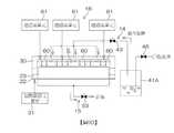
圖2為所述基板處理裝置所具備的氣體處理單元的示意圖。2 is a schematic diagram of a gas processing unit included in the substrate processing apparatus.
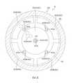
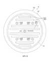
圖3為沿著圖2的III-III線的剖面的示意圖。FIG. 3 is a schematic diagram of a cross section taken along line III-III of FIG. 2.
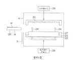
圖4為用以說明所述氣體處理單元所具備的混合氣體供給單元及排氣單元的構成的示意圖。4 is a schematic diagram for explaining the configuration of a mixed gas supply unit and an exhaust unit included in the gas processing unit.
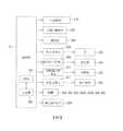
圖5為用以說明所述基板處理裝置的主要部分的電路構成的區塊圖。5 is a block diagram for explaining the circuit configuration of the main part of the substrate processing apparatus.
圖6為用以說明利用所述基板處理裝置的基板處理的一例的流程圖。6 is a flowchart for explaining an example of substrate processing using the substrate processing apparatus.
圖7為表示實行圖6所示的基板處理前後的基板剖面狀態的示意圖。7 is a diagram showing the cross-sectional state of the substrate before and after performing the substrate processing shown in FIG. 6Schematic.
圖8為表示圖6所示的乾式處理步驟(圖6的步驟S2)的一例的流程圖。FIG. 8 is a flowchart showing an example of the dry processing procedure shown in FIG. 6 (step S2 in FIG. 6).
圖9A為用以說明所述乾式處理步驟的示意圖。FIG. 9A is a schematic diagram illustrating the dry processing steps.
圖9B為用以說明所述乾式處理步驟的示意圖。9B is a schematic diagram illustrating the dry processing steps.
圖9C為用以說明所述乾式處理步驟的示意圖。FIG. 9C is a schematic diagram illustrating the dry processing steps.
圖9D為用以說明所述乾式處理步驟的示意圖。9D is a schematic diagram illustrating the dry processing steps.
圖10為用以將氧化劑的氧化電位與共價鍵的鍵能進行比較的圖表。FIG. 10 is a graph for comparing the oxidation potential of an oxidant with the bond energy of a covalent bond.
圖11為本實施形態的第一變形例的氣體處理單元的示意圖。FIG. 11 is a schematic diagram of a gas processing unit according to a first modification of this embodiment.
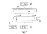
圖12為本實施形態的第二變形例的氣體處理單元的示意圖。12 is a schematic diagram of a gas processing unit according to a second modification of this embodiment.
圖13為從下方觀看本實施形態的第三變形例的氣體處理單元的罩的示意圖。FIG. 13 is a schematic view of a cover of a gas processing unit according to a third modification of this embodiment from below.
圖1為用以說明本發明的一實施形態的基板處理裝置1的內部佈局的圖解平面圖。FIG. 1 is a schematic plan view for explaining the internal layout of a
基板處理裝置1為對矽晶圓等基板W逐片進行處理的單片式裝置。基板處理裝置1含有:負載埠LP,分別保持收容基板W的多個載體C;以及多個處理單元2,以處理流體對自多個負載埠LP搬送來的基板W進行處理。處理流體中,包含對基板W進行處理的氣體即處理氣體、及對基板W進行處理的液體即處理液。The
基板處理裝置1含有:配置於從多個負載埠LP延伸至多個處理單元2的搬送路徑上的分度機械手(indexer robot)IR、搬運梭(shuttle)SH及主搬送機械手CR;以及控制基板處理裝置1的控制器3。The
分度機械手IR於多個負載埠LP與搬運梭SH之間搬送基板W。搬運梭SH於分度機械手IR與主搬送機械手CR之間搬送基板W。主搬送機械手CR於搬運梭SH與多個處理單元2之間搬送基板W。圖1所示的粗線的箭頭表示分度機械手IR的移動方向、或搬運梭SH的移動方向。The index robot IR transfers the substrate W between the load ports LP and the transfer shuttle SH. The transfer shuttle SH transfers the substrate W between the index robot IR and the main transfer robot CR. The main transfer robot CR transfers the substrate W between the transfer shuttle SH and the plurality of
多個處理單元2形成分別配置於水平地分離的四個位置的四個塔(tower)。各塔含有於上下方向上積層的多個處理單元2。於搬送路徑的兩側各配置有兩個塔。多個處理單元2包含保持基板W乾燥的狀態而對該基板W進行處理的多個乾式處理單元2D、及以處理液對基板W進行處理的多個濕式處理單元2W。負載埠LP側的兩個塔是由多個乾式處理單元2D構成。其餘兩個塔是由多個濕式處理單元2W構成。The plurality of
濕式處理單元2W含有:濕式腔室9,設有基板W通過的搬入搬出口;擋閘10,將濕式腔室9的搬入搬出口開閉;自旋夾盤11,在濕式腔室9內水平地保持基板W,並且使基板W繞通過基板W的中心部的旋轉軸線A1旋轉;以及多個噴嘴,向經自旋夾盤11保持的基板W噴出處理液。多個噴嘴中,包含噴出化學藥液的化學藥液噴嘴12及噴出淋洗液的淋洗液噴嘴13。The
乾式處理單元2D含有:乾式腔室4,設有基板W通過的搬入搬出口;擋閘5,將乾式腔室4的搬入搬出口開閉;以及氣體處理單元8,利用水蒸氣與臭氧氣體(O3氣體)的混合氣體對基板W進行處理。The
圖2為用以說明氣體處理單元8的構成例的示意圖。FIG. 2 is a schematic diagram for explaining a configuration example of the
氣體處理單元8含有:支持構件23,以基板W成為水平姿勢的方式自下方支持基板W;加熱器22,藉由加熱支持構件23而將經支持構件23支持的基板W加熱;罩30,自上方與支持構件23相向;以及罩升降單元29,使罩30相對於支持構件23及底環27而升降。氣體處理單元8更含有:底環27,自下方支持罩30;O型環28,將罩30與底環27之間密閉;多個提升銷24,於支持構件23與罩30之間水平地支持基板W;以及提升銷升降單元26,使多個提升銷24升降。The
加熱器22連接於對加熱器22供給電力的加熱器通電單元31。本實施形態中,加熱器22自下方鄰接於支持構件23,但亦可與本實施形態不同而配置於支持構件23的內部。The
支持構件23含有:配置於基板W的下方的圓板狀的底座部23b、自底座部23b的上表面向上方突出的多個半球狀的突出部23a、及自底座部23b的外周面向外側突出的圓環狀的凸緣部23c。底座部23b的上表面與基板W的下表面平行,且具有超出基板W的外徑的外徑。多個突出部23a在向上方遠離底座部23b的上表面的位置與基板W的下表面接觸。多個突出部23a以水平地支持基板W的方式配置於底座部23b的上表面內的多個位置。基板W是基板W的下表面在上方與底座部23b的上表面分離的狀態下受到水平支持。凸緣部23c上連結有底環27。The supporting
乾式處理單元2D亦可含有:將經加熱器22加熱的基板W於乾式腔室4內冷卻的冷卻單元7(參照圖1)、及於乾式腔室4內對經氣體處理單元8加熱的基板W進行搬送的室內搬送機構6(參照圖1)。The
多個提升銷24分別插入至貫通支持構件23的多個貫通孔中。藉由包圍提升銷24的波紋管25而防止流體從氣體處理單元8之外向貫通孔進入。對氣體處理單元8而言,代替波紋管25的亦可是除了波紋管25以外還具備O型環,該O型環將提升銷24的外周面與貫通孔的內周面之間的間隙密閉。提升銷24含有與基板W的下表面接觸的半球狀的上端部。多個提升銷24的上端部配置於相同高度。The plurality of lift pins 24 are inserted into the plurality of through holes of the through
提升銷升降單元26使多個提升銷24於鉛垂方向上於上位置與下位置之間移動,所述上位置為多個提升銷24的上端部位於較支持構件23更靠上方的位置(圖9A及圖9B所示的位置),所述下位置為多個提升銷24的上端部退避至支持構件23的內部的位置(圖2所示的位置)。提升銷升降單元26可為電動馬達或氣缸,或亦可為該些以外的致動器。The lifting
罩升降單元29使罩30於上位置(圖9A所示的位置)與下位置(圖2所示的位置)之間鉛垂地移動。上位置為罩30的下表面在上方與底環27的上表面分離的位置,以使基板W可於罩30的下表面與底環27的上表面之間通過。下位置為將罩30的下表面與底環27的上表面之間的間隙密閉而形成空間S的位置,所述空間S收容經支持構件23支持的基板W。罩升降單元29可為電動馬達或氣缸,或亦可為該等以外的致動器。The
氣體處理單元8更含有:混合氣體供給單元14,向基板W的上表面供給混合氣體;排氣單元15,對空間S進行排氣;以及紫外線照射單元16,向基板W的上表面照射紫外線。The
混合氣體供給單元14含有:多個混合氣體噴嘴40,向基板W的上表面噴出混合氣體;混合氣體供給管42,將來自混合氣體供給源41的混合氣體供給於多個混合氣體噴嘴40;以及混合氣體閥43,插入至混合氣體供給管42中。多個混合氣體噴嘴40具有在罩30的下表面中與基板W相向的位置開口的噴出口40a。混合氣體閥43切換是否向多個混合氣體噴嘴40供給混合氣體。The mixed
排氣單元15含有:排氣管52,具有在支持構件23的上表面開口的多個排出口50a,且排氣管52將空間S內的氣體引導至空間S外;以及排氣閥53,插入至排氣管52中,且對其流路進行開閉。The
紫外線照射單元16含有多個紫外線燈60、及連接於多個紫外線燈60的燈通電單元61。紫外線燈60藉由自燈通電單元61供電而發出紫外線。本實施形態中,對各紫外線燈60分別設置一個燈通電單元61,亦可對多個紫外線燈60設置共同的燈通電單元。多個紫外線燈60是安裝於罩30的下表面,且至少其一部分與基板W相向。紫外線燈60例如是由照射185nm的紫外線的低壓水銀燈所構成。The
圖3為沿著圖2的III-III線的剖面的示意圖。FIG. 3 is a schematic diagram of a cross section taken along line III-III of FIG. 2.
多個混合氣體噴嘴40中,包含中心噴嘴40A及多個外周噴嘴40B,所述中心噴嘴40A具有開口在與基板W的中心部相向的位置的噴出口40a,所述外周噴嘴40B具有開口在與基板W的外周部相向的位置的噴出口40a。所謂基板W的中心部,為俯視時位於基板W的中心的部分。所謂基板W的外周部,為俯視時基板W的中心部與基板W的周緣部之間的部分。多個外周噴嘴40B是圍繞通過基板W的中心部的鉛垂線A2而等間隔地配置。外周噴嘴40B例如是以90°間隔而設有共計四個。The plurality of
紫外線燈60包含與基板W的中心部附近相向的中心燈60A、及與基板W的外周部相向的多個外周燈60B。中心燈60A於俯視時將中心噴嘴40A包圍,且位於較多個外周噴嘴40B更靠鉛垂線A2側。多個外周燈60B是圍繞鉛垂線A2而等間隔地配置。多個外周燈60B例如是以90°間隔而設有共計四個。多個外周燈60B位於較多個外周噴嘴40B更靠與鉛垂線A2側相反之側。多個外周燈60B亦與基板W的周緣部相向。The
圖4為用以說明氣體處理單元8所具備的混合氣體供給單元14及排氣單元15的構成的示意圖。4 is a schematic diagram for explaining the configurations of the mixed
混合氣體供給源41含有:儲罐41A,蓄積有液態水;以及臭氧氣體供給單元41B,對儲罐41A中蓄積的液態水供給臭氧氣體。臭氧氣體供給單元41B含有:臭氧氣體噴嘴44,對儲罐41A內的水供給臭氧氣體;臭氧供給管45,將來自臭氧氣體供給源的臭氧氣體供給於臭氧氣體噴嘴44;以及臭氧氣體閥46,插入至臭氧供給管45中。臭氧氣體噴嘴44具有配置於儲罐41A內的水中的噴出口44a。臭氧氣體閥46切換是否向臭氧氣體噴嘴44供給臭氧氣體。The mixed
混合氣體供給單元14的混合氣體供給管42含有插入有混合氣體閥43的主配管42A、以及從主配管42A的另一端分支的多個分支配管42B。主配管42A具有設於儲罐41A內較水面更靠上方的位置的吸氣口42a。分支配管42B是以與混合氣體噴嘴40相同的數量而設置,各分支配管42B連結於對應的混合氣體噴嘴40。The mixed
排氣單元15的排氣管52含有插入有排氣閥53及過濾器54的主配管52A、以及從主配管52A分支的多個分支配管52B。各分支配管52B分別具有一個排出口50a(亦參照圖2)。過濾器54用於對從空間S中排出的氣體進行過濾。The
混合氣體閥43、臭氧氣體閥46、儲罐41A、排氣閥53及過濾器54是配置於與乾式腔室4鄰接的流體箱17內。The
圖5為用以說明基板處理裝置1的主要部分的電路構成的區塊圖。控制器3具備微電腦,按照既定的程式來控制基板處理裝置1所具備的控制對象。更具體而言,控制器3含有處理器(中央處理單元(Central Processing Unit,CPU))3A、及儲存有程式的記憶體3B,且以藉由處理器3A執行程式而實行用於基板處理的各種控制的方式構成。尤其控制器3控制分度機械手IR、主搬送機械手CR、搬運梭SH、提升銷升降單元26、罩升降單元29、加熱器通電單元31、燈通電單元61、氣體閥43、臭氧氣體閥46、排氣閥53以及濕式處理單元2W等的動作。FIG. 5 is a block diagram for explaining the circuit configuration of the main part of the
圖6為表示藉由基板處理裝置1所實行的基板W的處理的一例的步驟圖,主要表示藉由控制器3執行程式而實現的處理。圖7為表示實行圖6所示的基板W的處理的一例之前與實行處理之後的基板W的剖面的示意圖。FIG. 6 is a step diagram showing an example of the processing of the substrate W performed by the
如圖7的左側所示,利用基板處理裝置1進行處理的基板W為進行蝕刻處理步驟後的基板,所述蝕刻處理步驟對經抗蝕劑的圖案PR覆蓋的薄膜進行蝕刻,形成薄膜的圖案PF。即,將收容有此種基板W的載體C置於負載埠LP上。如以下將說明般,於利用基板處理裝置1的基板處理中,將位於薄膜的圖案PF上的抗蝕劑的圖案PR去除(抗蝕劑去除步驟)。圖7的右側表示進行抗蝕劑去除步驟後的基板W的剖面。As shown on the left side of FIG. 7, the substrate W processed by the
在利用基板處理裝置1對基板W進行處理時,分度機械手IR、搬運梭SH及主搬送機械手CR將置於負載埠LP上的載體C內的基板W搬送至乾式處理單元2D(圖6的步驟S1)。在乾式處理單元2D中,進行利用混合氣體對基板W進行處理的乾式處理步驟(圖6的步驟S2)。然後,主搬送機械手CR將乾式處理單元2D內的基板W搬入至濕式處理單元2W中(圖6的步驟S3)。When processing the substrate W by the
在濕式處理單元2W中,進行一面使基板W旋轉一面對基板W的上表面供給處理液的濕式處理步驟(圖6的步驟S4)。具體而言,進行一面使基板W旋轉,一面使化學藥液噴嘴12向基板W的上表面噴出化學藥液的化學藥液供給步驟。然後,進行一面使基板W旋轉,一面使淋洗液噴嘴13向基板W的上表面噴出淋洗液的淋洗液供給步驟。其後,進行藉由使基板W高速旋轉而使基板W乾燥的乾燥步驟。繼而,分度機械手IR、搬運梭SH及主搬送機械手CR將濕式處理單元2W內的基板W搬送至置於負載埠LP上的載體C上(圖6的步驟S5)。In the
圖8為表示乾式處理步驟(圖6的步驟S2)的一例的流程圖。圖9A~圖9D為用以說明乾式處理步驟(圖6的步驟S2)的示意圖。8 is a flowchart showing an example of a dry processing procedure (step S2 in FIG. 6). 9A-9D are schematic diagrams for explaining the dry processing steps (step S2 of FIG. 6).
如圖9A所示,於將基板W搬入至乾式處理單元2D中時,罩升降單元29使罩位於上位置,提升銷升降單元26使多個提升銷24位於上位置。於該狀態下,主搬送機械手CR一面以手部H支持基板W,一面使手部H進入乾式腔室4內。然後,將已使作為元件形成面的表面朝上的基板W置於多個提升銷24上。主搬送機械手CR將手部H上的基板W交給乾式處理單元2D後,使手部H移動至乾式腔室4之外。其後,關閉乾式腔室4的搬入搬出口。如此,向乾式腔室4內的基板W的搬入完成(步驟T1)。基板W可藉由主搬送機械手CR的手部H而置於多個提升銷24上,亦可藉由室內搬送機構6(參照圖1)而置於多個提升銷24上。As shown in FIG. 9A, when the substrate W is carried into the
如圖9B所示,罩升降單元29使罩30移動至下位置(步驟T2)。藉此,於罩30與支持構件23之間形成收容基板W的空間S(空間形成步驟)。罩30及支持構件23具有作為收容基板W的空間形成單元的功能。然後,提升銷升降單元26使多個提升銷24移動至下位置。於多個提升銷24移動至下位置的過程中,基板W由支持構件23承接,自多個提升銷24交付至支持構件23。藉此,基板W經支持構件23支持(支持步驟)。As shown in FIG. 9B, the
從基板W經支持構件23支持之前開始,加熱器通電單元31對加熱器22進行通電。因此,支持構件23是從基板W經支持構件23支持之前開始由加熱器22加熱。支持構件23維持於較室溫高的溫度(例如100℃以上)。若基板W經支持構件23支持,則開始加熱基板W(步驟T3)。The
接著,如圖9C所示,打開臭氧氣體閥46,將臭氧氣體送入儲罐41A內的水中。詳細而言,藉由起泡而使臭氧氣體的氣泡於儲罐41A內的水中通過。藉此,於氣泡內產生水蒸氣,該水蒸氣與臭氧氣體混合而形成混合氣體(混合氣體形成步驟)。繼而,打開混合氣體閥43,經由儲罐41A及混合氣體供給管42,自多個混合氣體噴嘴40的噴出口40a噴出混合氣體(步驟T4)。即,實行混合氣體噴出步驟。藉此,對空間S內供給混合氣體。Next, as shown in FIG. 9C, the
繼而,打開排氣閥53(步驟T5)。藉此,利用混合氣體將空間S內的空氣擠出至空間S的外部。藉由繼續向空間S供給混合氣體,而於空間S內充滿混合氣體。藉由在空間S內充滿混合氣體,而對基板W的上表面附近亦充分供給混合氣體(混合氣體供給步驟)。Then, the
另外,於對基板W的上表面附近供給混合氣體的期間中,亦藉由加熱器22將基板W加熱(第一加熱步驟)。即,第一加熱步驟是與混合氣體供給步驟同時進行。加熱器22具有作為加熱基板W的第一加熱單元的功能。In addition, during the period when the mixed gas is supplied near the upper surface of the substrate W, the substrate W is also heated by the heater 22 (first heating step). That is, the first heating step is performed simultaneously with the mixed gas supply step. The
繼而,如圖9D所示,於將混合氣體供給於基板W的上表面附近的狀態下,對紫外線燈60進行通電,藉此自紫外線燈60照射紫外線(步驟T6)。藉此,對基板W的上表面附近的混合氣體照射紫外線(紫外線照射步驟)。Next, as shown in FIG. 9D, in a state where the mixed gas is supplied near the upper surface of the substrate W, the
於開始對基板W的上表面附近的混合氣體照射紫外線之前(紫外線照射步驟之前),已形成有空間S。另外,於對基板W的上表面附近的混合氣體照射紫外線的期間中,亦將排氣閥53維持於打開狀態。因此,對空間S進行排氣的排氣步驟是在紫外線照射步驟的實行中進行。Before starting to irradiate the mixed gas near the upper surface of the substrate W with ultraviolet rays (before the ultraviolet irradiation step), the space S has been formed. In addition, the
另外,於對基板W的上表面附近的混合氣體照射紫外線的期間中,亦藉由加熱器22將基板W加熱(第二加熱步驟)。即,第二加熱步驟是與紫外線照射步驟同時進行。加熱器22具有作為加熱基板W的第二加熱單元的功能。本實施形態中,藉由加熱器22加熱基板W,而同時實行第一加熱步驟與第二加熱步驟。In addition, during the period in which the mixed gas near the upper surface of the substrate W is irradiated with ultraviolet rays, the substrate W is also heated by the heater 22 (second heating step).That is, the second heating step is performed simultaneously with the ultraviolet irradiation step. The
下文中將詳細描述,藉由對基板W的上表面附近的混合氣體照射紫外線,而將形成於基板W的上表面的抗蝕劑氧化並加以分解。結果,將抗蝕劑的圖案PR自基板W的上表面去除。As will be described in detail below, by irradiating the mixed gas near the upper surface of the substrate W with ultraviolet rays, the resist formed on the upper surface of the substrate W is oxidized and decomposed. As a result, the pattern PR of the resist is removed from the upper surface of the substrate W.
繼而,進行既定時間的紫外線照射之後,自基板W的上表面停止燈通電單元61對紫外線燈60的通電(步驟T7)。然後,關閉混合氣體閥43,停止向空間S供給混合氣體(步驟T8)。繼而,關閉排氣閥53,停止空間S的排氣(步驟T9)。其後,藉由多個提升銷24將支持構件23上的基板W提起(步驟T10),罩升降單元29使罩30上升至上位置(步驟T11)。Then, after performing ultraviolet irradiation for a predetermined time, the energization of the
於基板W經冷卻單元7(參照圖1)冷卻之後,主搬送機械手CR以手部H承接基板W。其後,主搬送機械手CR將手部H上的基板W搬入至濕式處理單元2W中。如此,乾式腔室4內的基板W的搬出完成(步驟T12)。After the substrate W is cooled by the cooling unit 7 (see FIG. 1 ), the main transport robot CR receives the substrate W with the hand H. Thereafter, the main transfer robot CR transfers the substrate W on the hand H into the
根據本實施形態,對藉由支持構件23水平地支持的基板W的上表面附近,供給使水蒸氣與臭氧氣體混合而成的混合氣體。而且,藉由自紫外線照射單元16對混合氣體照射紫外線而產生羥基自由基(.OH)。詳細而言,首先藉由紫外線的照射,如下述化1式般將水蒸氣(H2O)分解,產生羥基自由基(.OH)及氫自由基(.H)。According to this embodiment, a mixed gas obtained by mixing water vapor and ozone gas is supplied to the vicinity of the upper surface of the substrate W horizontally supported by the
[化1]化1 H2O→‧OH+‧H[化1]化1 H2 O→‧OH+‧H
繼而,如下述化2式般,氫自由基(.H)與臭氧(O3)反應而產生羥基自由基(.OH)及氧(O2)。Then, as shown in the following
[化2]化2 ‧H+O3→‧OH+O2[化2]化2 ‧H+O3 →‧OH+O2
因此,可藉由水蒸氣(H2O)的分解、及氫自由基(.H)與臭氧(O3)的反應而產生充分量的羥基自由基(.OH)。Therefore, a sufficient amount of hydroxyl radicals (.OH) can be generated by the decomposition of water vapor (H2 O) and the reaction of hydrogen radicals (.H) with ozone (O3 ).
進而,由於對基板W的上表面供給水蒸氣(氣體水),故可抑制水滴(液態水)附著於基板W的上表面。因此,可不受液態水吸收紫外線的妨礙而於基板W的上表面附近使臭氧分解。Furthermore, since water vapor (gas water) is supplied to the upper surface of the substrate W, the adhesion of water droplets (liquid water) to the upper surface of the substrate W can be suppressed. Therefore, ozone can be decomposed in the vicinity of the upper surface of the substrate W without being hindered by the absorption of ultraviolet rays by liquid water.
藉由如此般產生的羥基自由基及臭氧將構成抗蝕劑的酚樹脂氧化。藉此,將酚樹脂分解成乙酸或草酸等低級羧酸。繼而,藉由羥基自由基及臭氧將該些低級羧酸進一步氧化,分解成二氧化碳與水。如此般藉由羥基自由基及臭氧將抗蝕劑分解。The hydroxyl radicals and ozone generated in this way oxidize the phenol resin constituting the resist. By this, the phenol resin is decomposed into lower carboxylic acids such as acetic acid or oxalic acid. Subsequently, these lower carboxylic acids are further oxidized by hydroxyl radicals and ozone to be decomposed into carbon dioxide and water. In this way, the resist is decomposed by hydroxyl radicals and ozone.
如以上般,藉由充分量的羥基自由基將形成於基板W的上表面的抗蝕劑分解,故而可將抗蝕劑自基板W的表面良好地去除。As described above, the resist formed on the upper surface of the substrate W is decomposed by a sufficient amount of hydroxyl radicals, so the resist can be removed from the surface of the substrate W satisfactorily.
再者,羥基自由基的壽命為1.0×10⁻⁶sec,而根據本實施形態的構成(方法),可於基板W的上表面附近產生羥基自由基。因此,可於羥基自由基消失之前使分解抗蝕劑的羥基自由基的量增大。In addition, the lifetime of the hydroxyl radical is 1.0×10⁻⁶ sec. According to the configuration (method) of this embodiment, the hydroxyl radical can be generated near the upper surface of the substrate W. Therefore, the amount of hydroxyl radicals that decompose the resist can be increased before the hydroxyl radicals disappear.
換言之,本實施形態中,紫外線照射步驟包括以下步驟:藉由紫外線的照射而於基板W的上表面附近產生羥基自由基的步驟;以及藉由羥基自由基將抗蝕劑分解的步驟。因此,可利用藉由自紫外線照射單元16照射紫外線而產生的羥基自由基將抗蝕劑確實地分解。In other words, in the present embodiment, the ultraviolet irradiation step includes the following steps: a step of generating hydroxyl radicals near the upper surface of the substrate W by irradiation of ultraviolet rays; and a step of decomposing the resist by hydroxyl radicals. Therefore, the hydroxyl radicals generated by irradiating ultraviolet rays from the
此處,對抗蝕劑的分解機制進行說明。構成形成於基板W的表面的抗蝕劑的分子內,含有碳彼此的雙鍵(C=C),藉由氧化將該雙鍵切斷,由此將抗蝕劑分解。Here, the decomposition mechanism of the resist will be described. The molecules constituting the resist formed on the surface of the substrate W contain a double bond (C=C) between carbons, and the double bond is broken by oxidation, thereby decomposing the resist.
圖10為用以將氧化劑的氧化電位與共價鍵的鍵能進行比較的圖表。圖10所示的圖表的右半部分中,示出將有機化合物所含的代表性共價鍵切斷所需要的鍵能。圖10所示的圖表的左半部分中,作為代表性氧化劑的氧化能力的指標而示出氧化電位。於氧化劑的氧化電位高於共價鍵的鍵能的情形時,藉由氧化將共價鍵切斷。如圖10所示,碳彼此的雙鍵(C=C)的鍵能為1.5V。另一方面,臭氧(O3)的氧化電位為2.07V,羥基自由基(.OH)的氧化電位為2.81V。因此,臭氧(O3)及羥基自由基(.OH)均將碳彼此的雙鍵(C=C)氧化。由於羥基自由基(.OH)的氧化電位高於臭氧(O3)的氧化電位,故而藉由更多地產生羥基自由基,可將碳彼此的雙鍵(C=C)有效率地氧化。即,可將抗蝕劑有效率地分解。FIG. 10 is a graph for comparing the oxidation potential of an oxidant with the bond energy of a covalent bond. The right half of the graph shown in FIG. 10 shows the bond energy required to cut the representative covalent bond contained in the organic compound. The left half of the graph shown in FIG. 10 shows the oxidation potential as an index of the oxidation ability of a representative oxidant. When the oxidation potential of the oxidant is higher than the bond energy of the covalent bond, the covalent bond is cut by oxidation. As shown in FIG. 10, the bond energy of the double bond (C=C) between carbons is 1.5V. On the other hand, the oxidation potential of ozone (O3 ) is 2.07V, and the oxidation potential of hydroxyl radical (.OH) is 2.81V. Therefore, both ozone (O3 ) and hydroxyl radical (.OH) oxidize the double bond (C=C) of carbon. Since the oxidation potential of hydroxyl radicals (.OH) is higher than that of ozone (O3 ), the double bond (C=C) between carbons can be efficiently oxidized by generating more hydroxyl radicals. That is, the resist can be efficiently decomposed.
另外,根據本實施形態,實行加熱基板W的第一加熱步驟與混合氣體供給步驟同時並行。因此,藉由加熱器22將基板W的上表面附近的混合氣體加熱。因此,可抑制水蒸氣於基板W的上表面附近液化。In addition, according to this embodiment, the first heating of the heating substrate W is performedThe step is parallel to the mixed gas supply step. Therefore, the mixed gas near the upper surface of the substrate W is heated by the
另外,根據本實施形態,實行加熱基板W的第二加熱步驟與紫外線照射步驟同時並行。因此,藉由加熱器22將基板W的上表面附近所產生的抗蝕劑的分解物加熱。藉此,可使抗蝕劑的分解物昇華而成為氣體狀態。因此,可抑制抗蝕劑的分解物於基板W的上表面固化。故而可將形成於基板W的表面的抗蝕劑良好地去除。藉由實行加熱基板W的第二加熱步驟與紫外線照射步驟同時並行,於紫外線照射步驟中亦可抑制水蒸氣於基板W的上表面附近液化。In addition, according to the present embodiment, the second heating step of heating the substrate W and the ultraviolet ray irradiation step are performed simultaneously. Therefore, the
另外,根據本實施形態,於混合氣體供給步驟中,自噴出口40a向基板W的上表面噴出混合氣體(混合氣體噴出步驟)。藉此,混合氣體是自噴出口40a向基板W的上表面噴出。因此,與從各別的噴出口向基板W的上表面噴出水蒸氣與臭氧氣體的構成相比較,可於基板W的整個上表面,確保基板W的上表面附近的水蒸氣與臭氧氣體的比例(比率)均等。In addition, according to the present embodiment, in the mixed gas supply step, the mixed gas is ejected from the
另外,根據本實施形態,於紫外線照射步驟開始之前形成空間S(空間形成步驟),且於紫外線照射步驟的實行中對空間S內進行排氣(排氣步驟)。In addition, according to this embodiment, the space S is formed before the start of the ultraviolet irradiation step (space formation step), and the inside of the space S is exhausted during the execution of the ultraviolet irradiation step (exhaust step).
藉此,於對基板W的上表面附近的混合氣體照射紫外線之前,將基板W收容於與外部阻斷的空間S內。因此,可於使空間S內(基板W的上表面附近的空間中)充滿混合氣體的狀態下照射紫外線。因此,可產生充分量的羥基自由基。另一方面,於紫外線的照射中,對空間S進行排氣。藉此,可於抗蝕劑的分解物於基板W的上表面固化之前,將抗蝕劑的分解物排出至空間S的外部。Thereby, before irradiating the mixed gas near the upper surface of the substrate W with ultraviolet rays, the substrate W is accommodated in the space S blocked from the outside. Therefore, it can be usedThe space S (in the space near the upper surface of the substrate W) is irradiated with ultraviolet rays while being filled with the mixed gas. Therefore, a sufficient amount of hydroxyl radicals can be generated. On the other hand, during the irradiation of ultraviolet rays, the space S is exhausted. Thereby, before the decomposition product of the resist is cured on the upper surface of the substrate W, the decomposition product of the resist can be discharged to the outside of the space S.
另外,根據本實施形態,自臭氧氣體供給單元41B對儲罐41A中蓄積的液態水供給臭氧氣體,藉此形成混合氣體(混合氣體形成步驟)。因此,於準備混合氣體時,無需與臭氧氣體相區別而另準備水蒸氣後將臭氧氣體與水蒸氣混合。即,和與臭氧氣體相區別而另準備水蒸氣的情形相比較,可簡單地準備混合氣體。In addition, according to the present embodiment, ozone gas is supplied from the ozone
圖11為本實施形態的第一變形例的氣體處理單元8的示意圖。第一變形例的氣體處理單元8中,對各混合氣體噴嘴40分別連結一根混合氣體供給管42。混合氣體供給管42包含:合流配管42C,連結於混合氣體噴嘴40;水蒸氣配管42D,將自水蒸氣供給源供給的水蒸氣供給於合流配管42C;以及臭氧氣體配管42E,將自臭氧氣體供給源供給的臭氧氣體供給於合流配管42C。水蒸氣配管42D內的水蒸氣與臭氧氣體配管42E內的臭氧氣體於合流配管42C內混合。自混合氣體噴嘴40供給在合流配管42C內經混合的混合氣體。而且,於水蒸氣配管42D中插入有對其流路進行開閉的水蒸氣閥43D。於臭氧氣體配管42E中插入有對其流路進行開閉的臭氧氣體閥43E。FIG. 11 is a schematic diagram of the
第一變形例的基板處理裝置1亦可實行與本實施形態的基板處理裝置1相同的基板處理。另外,第一變形例亦發揮與本實施形態相同的效果。另外,第一變形例中,藉由調整水蒸氣閥43D及臭氧氣體閥43E的開度,可調整混合氣體中的水蒸氣與臭氧氣體的成分比率(比例)。例如,若混合氣體中所含的水蒸氣過多,則水滴容易附著於基板W的上表面。另一方面,若混合氣體中所含的水蒸氣過少,則未充分產生羥基自由基。藉由調整混合氣體中的水蒸氣的比例,可充分產生羥基自由基並且抑制水滴對基板W的上表面的附著。The
圖12為本實施形態的第二變形例的氣體處理單元8的示意圖。第二變形例的氣體處理單元8是以從各別的噴出口80a、81a噴出水蒸氣與臭氧氣體的方式構成。混合氣體供給單元14含有噴出水蒸氣的水蒸氣噴嘴80及噴出臭氧氣體的臭氧氣體噴嘴81來代替混合氣體噴嘴40。水蒸氣噴嘴80具有噴出口80a。臭氧氣體噴嘴81具有噴出口81a。混合氣體供給單元14含有:水蒸氣供給管82,將來自水蒸氣供給源的水蒸氣供給於水蒸氣噴嘴80;水蒸氣閥83,插入到水蒸氣供給管82中,且對其流路進行開閉;臭氧氣體供給管84,將來自臭氧氣體供給源的臭氧氣體供給於臭氧氣體噴嘴81;以及臭氧氣體閥85,插入至臭氧氣體供給管84中,且對其流路進行開閉。將自水蒸氣噴嘴80噴出的水蒸氣與自臭氧氣體噴嘴81噴出的臭氧氣體於空間S內混合,藉此形成混合氣體。藉由在空間S內形成混合氣體,而對基板W的上表面附近供給混合氣體。FIG. 12 is a schematic diagram of a
第二變形例的基板處理裝置1亦實行與本實施形態的基板處理裝置1相同的基板處理。另外,第二變形例亦發揮與本實施形態相同的效果。The
本發明不限定於以上所說明的實施形態,可進而以其他形態實施。The present invention is not limited to the embodiments described above, and can be implemented in other forms.
例如,所述實施形態中,同時實行混合氣體供給步驟與紫外線照射步驟。然而,亦可與所述實施形態不同,停止供給混合氣體之後開始照射紫外線。即,圖8中,亦可於開始照射紫外線(步驟T6)之前停止供給混合氣體(步驟T8)。For example, in the above embodiment, the mixed gas supply step and the ultraviolet irradiation step are simultaneously performed. However, it may be different from the above-mentioned embodiment in that the supply of the mixed gas is stopped and the irradiation of ultraviolet rays is started. That is, in FIG. 8, the supply of the mixed gas may be stopped (step T8) before starting the ultraviolet ray irradiation (step T6).
於此種情形時,於第一加熱步驟結束後開始第二加熱步驟。因此,可於在混合氣體供給步驟中加熱基板W的第一加熱步驟、與在紫外線照射步驟中加熱基板W的第二加熱步驟中,變更加熱器22的溫度。例如,於抗蝕劑的分解物的昇華溫度、與不使水滴附著於基板W的表面所需要的溫度不同的情形時,可分別對應地變更第一加熱步驟中的基板W的溫度與第二加熱步驟中的基板W的溫度。另外,於第一加熱步驟結束後開始第二加熱步驟的情形時,亦可設置於第一加熱步驟中加熱基板W的第一加熱器及於第二加熱步驟中加熱基板W的第二加熱器來代替加熱器22。In this case, the second heating step starts after the end of the first heating step. Therefore, the temperature of the
另外,所述實施形態中,在開始供給混合氣體之前使罩30下降而形成空間S。然而,亦可與所述實施形態不同,開始供給混合氣體之後形成空間S。即,圖8中,亦可於罩下降(步驟T2)之前開始供給混合氣體(步驟T4)。In addition, in the above embodiment, the
另外,亦可與所述實施形態不同,排氣單元15含有連結於排氣管52且經由排出口50a對空間S進行排氣的真空泵等排氣泵(未圖示)。Also, unlike the above embodiment, the
另外,亦可與所述實施形態不同,如圖13所示,紫外線燈60含有直線狀地延伸的棒狀燈60C來代替中心燈60A及外周燈60B(參照圖3)。紫外線燈60不限定於該些形態,為了遍及基板W的整個表面產生羥基自由基,較佳為以與整個基板W相向的方式設置。In addition, it may be different from the above-mentioned embodiment. As shown in FIG. 13, the
另外,亦可如圖3中以二點鏈線所示,將混合氣體噴嘴40的多個外周噴嘴40B排列配置於與通過基板W的中心部的鉛垂線A2正交的徑向上。另外,於徑向上排列配置的多個外周噴嘴40B的列亦可繞鉛垂線A2而等間隔地配置。In addition, as shown by a two-dot chain line in FIG. 3, the plurality of outer
對本發明的實施形態詳細進行了說明,但該些說明僅為用於闡明本發明的技術內容的具體例,本發明不應限定於該些具體例而解釋,本發明的範圍是僅由隨附的申請專利範圍限定。The embodiments of the present invention have been described in detail, but these descriptions are only specific examples for clarifying the technical content of the present invention. The present invention should not be limited to these specific examples and explained, the scope of the present invention is only provided by the accompanying The scope of patent application is limited.
本申請案與2017年3月24日向日本專利廳提出申請的日本專利申請案2017-060073號對應,將該申請案揭示的所有內容以引用的方式併入至本文中。This application corresponds to Japanese Patent Application No. 2017-060073 filed with the Japanese Patent Office on March 24, 2017, and all contents disclosed in the application are incorporated herein by reference.
1:基板處理裝置1: substrate processing device
2:處理單元2: Processing unit
2D:乾式處理單元2D: Dry processing unit
2W:濕式處理單元2W: Wet processing unit
3:控制器3: controller
4:乾式腔室4: Dry chamber
5:擋閘5: blocking gate
6:室內搬送機構6: Indoor transport mechanism
7:冷卻單元7: Cooling unit
8:氣體處理單元8: Gas processing unit
9:濕式腔室9: Wet chamber
10:擋閘10: Brake
11:自旋夾盤11: Spin chuck
12:化學藥液噴嘴12: Chemical liquid nozzle
13:淋洗液噴嘴13: Eluent nozzle
17:流體箱17: fluid tank
A1:旋轉軸線A1: axis of rotation
C:載體C: carrier
CR:主搬送機械手CR: main transfer robot
H:手部H: hand
IR:分度機械手IR: Indexing robot
LP:負載埠LP: load port
SH:搬運梭SH: handling shuttle
W:基板W: substrate
Claims (10)
Translated fromChineseApplications Claiming Priority (2)
| Application Number | Priority Date | Filing Date | Title |
|---|---|---|---|
| JP2017060073AJP2018163980A (en) | 2017-03-24 | 2017-03-24 | Substrate processing method and substrate processing apparatus |
| JP2017-060073 | 2017-03-24 |
Publications (2)
| Publication Number | Publication Date |
|---|---|
| TW201838034A TW201838034A (en) | 2018-10-16 |
| TWI686867Btrue TWI686867B (en) | 2020-03-01 |
Family
ID=63585277
Family Applications (1)
| Application Number | Title | Priority Date | Filing Date |
|---|---|---|---|
| TW107107149ATWI686867B (en) | 2017-03-24 | 2018-03-05 | Substrate processing method and substrate processing apparatus |
Country Status (5)
| Country | Link |
|---|---|
| JP (1) | JP2018163980A (en) |
| KR (1) | KR20190112093A (en) |
| CN (1) | CN110366769A (en) |
| TW (1) | TWI686867B (en) |
| WO (1) | WO2018173525A1 (en) |
Families Citing this family (1)
| Publication number | Priority date | Publication date | Assignee | Title |
|---|---|---|---|---|
| JP7441620B2 (en)* | 2019-08-29 | 2024-03-01 | 株式会社Screenホールディングス | Substrate processing method |
Citations (2)
| Publication number | Priority date | Publication date | Assignee | Title |
|---|---|---|---|---|
| JPH04302145A (en)* | 1991-03-29 | 1992-10-26 | Hitachi Ltd | Cleaning method |
| JP2005136439A (en)* | 1999-12-03 | 2005-05-26 | Mitsubishi Electric Corp | Substrate processing method |
Family Cites Families (13)
| Publication number | Priority date | Publication date | Assignee | Title |
|---|---|---|---|---|
| JP3150509B2 (en)* | 1992-11-27 | 2001-03-26 | 株式会社日立製作所 | Organic matter removal method and apparatus for using the method |
| JP3671389B2 (en)* | 1999-12-03 | 2005-07-13 | 三菱電機株式会社 | Substrate processing method and apparatus |
| JP2000286251A (en) | 1999-03-31 | 2000-10-13 | Japan Storage Battery Co Ltd | Ultraviolet treatment device |
| JP4320982B2 (en)* | 2000-07-04 | 2009-08-26 | セイコーエプソン株式会社 | Substrate processing equipment |
| JP2002018379A (en)* | 2000-07-04 | 2002-01-22 | Seiko Epson Corp | Thin film peeling method, thin film peeling apparatus, and method of manufacturing electronic device |
| JP2001144080A (en)* | 2000-08-09 | 2001-05-25 | Hitachi Ltd | Surface treatment method and surface treatment device |
| JP3756092B2 (en)* | 2001-09-06 | 2006-03-15 | 大日本スクリーン製造株式会社 | Substrate processing equipment |
| JP2003273059A (en)* | 2002-03-19 | 2003-09-26 | Mitsubishi Electric Corp | Substrate processing method and apparatus |
| JP2004327610A (en)* | 2003-04-23 | 2004-11-18 | Mitsubishi Electric Corp | Method for removing photoresist from semiconductor wafer |
| JP5019741B2 (en)* | 2005-11-30 | 2012-09-05 | 東京エレクトロン株式会社 | Semiconductor device manufacturing method and substrate processing system |
| DE102009058962B4 (en) | 2009-11-03 | 2012-12-27 | Suss Microtec Photomask Equipment Gmbh & Co. Kg | Method and device for treating substrates |
| JP5782279B2 (en)* | 2011-01-20 | 2015-09-24 | 株式会社Screenホールディングス | Substrate processing method and substrate processing apparatus |
| JP2016219656A (en)* | 2015-05-22 | 2016-12-22 | ウシオ電機株式会社 | Optical processing apparatus and optical processing method |
- 2017
- 2017-03-24JPJP2017060073Apatent/JP2018163980A/enactivePending
- 2018
- 2018-02-07KRKR1020197025385Apatent/KR20190112093A/ennot_activeCeased
- 2018-02-07WOPCT/JP2018/004149patent/WO2018173525A1/ennot_activeCeased
- 2018-02-07CNCN201880013272.1Apatent/CN110366769A/enactivePending
- 2018-03-05TWTW107107149Apatent/TWI686867B/enactive
Patent Citations (2)
| Publication number | Priority date | Publication date | Assignee | Title |
|---|---|---|---|---|
| JPH04302145A (en)* | 1991-03-29 | 1992-10-26 | Hitachi Ltd | Cleaning method |
| JP2005136439A (en)* | 1999-12-03 | 2005-05-26 | Mitsubishi Electric Corp | Substrate processing method |
Also Published As
| Publication number | Publication date |
|---|---|
| TW201838034A (en) | 2018-10-16 |
| KR20190112093A (en) | 2019-10-02 |
| WO2018173525A1 (en) | 2018-09-27 |
| CN110366769A (en) | 2019-10-22 |
| JP2018163980A (en) | 2018-10-18 |
Similar Documents
| Publication | Publication Date | Title |
|---|---|---|
| TWI529795B (en) | Substrate treatment method and substrate treatment apparatus | |
| KR102741646B1 (en) | Substrate processing apparatus and a substrate processing method | |
| KR102827831B1 (en) | Rework of metal-containing photoresist | |
| CN102725440A (en) | Photoresist removing processor and methods | |
| US10991603B2 (en) | Apparatus and method for treating substrate | |
| JP6222818B2 (en) | Substrate processing method and substrate processing apparatus | |
| JP2008294453A (en) | Method and equipment for processing substrate, and computer-readable recording medium | |
| JP2012023366A (en) | Systems and methods for etching silicon nitride | |
| CN109478500B (en) | Substrate processing method and substrate processing apparatus | |
| JP2007273598A (en) | Substrate processor and substrate processing method | |
| TWI805354B (en) | Substrate processing method and substrate processing apparatus | |
| TWI818297B (en) | Substrate processing method and substrate processing device | |
| TWI686867B (en) | Substrate processing method and substrate processing apparatus | |
| JP2009188411A (en) | Silylation processing method, silylation processing apparatus, and etching processing system | |
| KR102847044B1 (en) | Apparatus for treating substrate | |
| JP2007103732A (en) | Method and apparatus for processing substrate | |
| JP2007109724A (en) | Method for removing resist film, control program, computer readable storage medium | |
| TWI898209B (en) | Substrate processing method and substrate processing device | |
| JP2021086993A (en) | Substrate processing method and substrate processing device | |
| TW202401514A (en) | Substrate processing method and substrate processing apparatus | |
| JP2005353978A (en) | Method and device for silylation processing | |
| JP2006286830A (en) | Method and apparatus for removing resist |