TWI686735B - Integrated touch display device and driving method thereof - Google Patents
Integrated touch display device and driving method thereofDownload PDFInfo
- Publication number
- TWI686735B TWI686735BTW107141320ATW107141320ATWI686735BTW I686735 BTWI686735 BTW I686735BTW 107141320 ATW107141320 ATW 107141320ATW 107141320 ATW107141320 ATW 107141320ATW I686735 BTWI686735 BTW I686735B
- Authority
- TW
- Taiwan
- Prior art keywords
- touch
- display
- light
- signal
- driving
- Prior art date
Links
Images


Classifications
- G—PHYSICS
- G06—COMPUTING OR CALCULATING; COUNTING
- G06V—IMAGE OR VIDEO RECOGNITION OR UNDERSTANDING
- G06V40/00—Recognition of biometric, human-related or animal-related patterns in image or video data
- G06V40/10—Human or animal bodies, e.g. vehicle occupants or pedestrians; Body parts, e.g. hands
- G06V40/12—Fingerprints or palmprints
- G06V40/13—Sensors therefor
- G06V40/1318—Sensors therefor using electro-optical elements or layers, e.g. electroluminescent sensing
Landscapes
- Engineering & Computer Science (AREA)
- Human Computer Interaction (AREA)
- Physics & Mathematics (AREA)
- General Physics & Mathematics (AREA)
- Multimedia (AREA)
- Theoretical Computer Science (AREA)
- Image Input (AREA)
- User Interface Of Digital Computer (AREA)
Abstract
Description
Translated fromChinese本揭示內容係關於一種整合型觸控顯示裝置,特別是一種兼具顯示、觸控偵測及指紋辨識之裝置。The present disclosure relates to an integrated touch display device, particularly a device that combines display, touch detection and fingerprint identification.
隨著科技的發展,「資訊安全」成為消費者在使用電子裝置時的一大重要考量。因此,許多電子裝置設計有使用者認證機制(Authentication),以控制資料的存取。在各種認證機制中,又以「指紋辨識」最為常見,因為「指紋辨識」易於整合在電子裝置中,且是根據生物特徵進行辨識,具有較高的安全性。With the development of technology, "information security" has become an important consideration for consumers when using electronic devices. Therefore, many electronic devices are designed with a user authentication mechanism (Authentication) to control data access. Among various authentication mechanisms, "fingerprint identification" is the most common, because "fingerprint identification" is easy to be integrated in electronic devices, and is identified based on biological characteristics, which has high security.
目前,顯示裝置上常需要具備觸控功能或指紋辨識功能,因此,需要針對市場的需求,設計顯示裝置之結構及其驅動方法。At present, the display device often needs to have a touch function or a fingerprint recognition function. Therefore, it is necessary to design the structure of the display device and its driving method in response to market demand.
本揭示內容之一態樣係一種整合型觸控顯示裝置。整合型觸控顯示裝置包含顯示面板、觸控電路及光感電路。顯示面板包含複數個資料線及複數個掃描線。該些資料線電性連接於資料驅動單元,該些掃描線電性連接於掃描驅動單元,使得顯示面板用以根據顯示驅動訊號於一幀週期間更新顯示畫面。觸控電路設置於顯示面板之第一基板上,電性連接於觸控偵測單元,用以根據觸控驅動訊號執行觸控偵測。光感電路設置於顯示面板之第二基板上,電性連接於指紋辨識單元,用以根據光感驅動訊號執行指紋辨識。整合型觸控顯示裝置根據觸控驅動訊號或/及顯示驅動訊號決定是否致能光感驅動訊號。One aspect of the disclosure is an integrated touch display device. The integrated touch display device includes a display panel, a touch circuit and a light sensing circuit. The display panel includes a plurality of data lines and a plurality of scan lines. SomeThe data lines are electrically connected to the data driving unit, and the scanning lines are electrically connected to the scanning driving unit, so that the display panel is used to update the display frame during a frame period according to the display driving signal. The touch circuit is disposed on the first substrate of the display panel and is electrically connected to the touch detection unit for performing touch detection according to the touch driving signal. The light-sensing circuit is disposed on the second substrate of the display panel, and is electrically connected to the fingerprint recognition unit for performing fingerprint recognition according to the light-sensing driving signal. The integrated touch display device determines whether to enable the light-sensing drive signal according to the touch drive signal or/and the display drive signal.
本揭示內容之另一態樣係一種驅動方法,應用於一整合型觸控顯示裝置。驅動方法包含下列步驟:透過顯示面板,根據顯示驅動訊號更新顯示畫面。透過觸控電路,根據觸控驅動訊號進行觸控偵測。根據觸控驅動訊號或/及顯示驅動訊號,致能光感驅動訊號,以透過光感電路掃描指紋辨識區域。在顯示驅動訊號或觸控驅動訊號處於致能準位時,禁能光感驅動訊號。Another aspect of the present disclosure is a driving method applied to an integrated touch display device. The driving method includes the following steps: updating the display screen according to the display driving signal through the display panel. Through the touch circuit, touch detection is performed according to the touch drive signal. According to the touch driving signal or/and the display driving signal, the light-sensing driving signal is enabled to scan the fingerprint recognition area through the light-sensing circuit. When the display driving signal or the touch driving signal is in the enabling level, the light-sensing driving signal is disabled.
如此,由於整合型觸控顯示裝置能在確認觸控驅動訊號與顯示驅動訊號之當前狀態後,判斷觸控驅動訊號與顯示驅動訊號是否會對光感驅動訊號造成干擾,再根據判斷結果致能光感驅動訊號,因此,能確保指紋辨識的精確度。In this way, the integrated touch display device can determine whether the touch drive signal and the display drive signal will cause interference to the light-sensing drive signal after confirming the current state of the touch drive signal and the display drive signal, and then enable according to the judgment result The light-sensing driving signal can therefore ensure the accuracy of fingerprint recognition.
100‧‧‧整合型觸控顯示裝置100‧‧‧Integrated touch display device
110‧‧‧顯示面板110‧‧‧Display panel
111‧‧‧第一基板111‧‧‧The first substrate
112‧‧‧第二基板112‧‧‧Second substrate
112a‧‧‧第一控制器112a‧‧‧First controller
112b‧‧‧第二控制器112b‧‧‧Second controller
113‧‧‧驅動層113‧‧‧Drive layer
113a‧‧‧畫素電極113a‧‧‧Pixel electrode
114‧‧‧液晶層114‧‧‧Liquid crystal layer
120‧‧‧觸控電路120‧‧‧Touch circuit
130‧‧‧光感電路130‧‧‧Light sensing circuit
140‧‧‧處理電路140‧‧‧ processing circuit
141‧‧‧資料驅動單元141‧‧‧Data drive unit
142‧‧‧掃描驅動單元142‧‧‧ Scan drive unit
143‧‧‧觸控偵測單元143‧‧‧Touch detection unit
144‧‧‧指紋辨識單元144‧‧‧fingerprint identification unit
150‧‧‧背光元件150‧‧‧Backlight components
Sc‧‧‧光感驅動訊號Sc‧‧‧Light drive signal
Sd‧‧‧顯示驅動訊號Sd‧‧‧Display drive signal
St‧‧‧觸控驅動訊號St‧‧‧Touch drive signal
Se‧‧‧增強訊號Se‧‧‧Enhanced signal
Sy‧‧‧同步訊號Sy‧‧‧Sync signal
stv‧‧‧開始訊號stv‧‧‧Start signal
ckv‧‧‧時脈訊號ckv‧‧‧clock signal
ckv_w‧‧‧時脈訊號ckv_w‧‧‧clock signal
oe‧‧‧致能訊號oe‧‧‧Enable signal
TP‧‧‧觸控訊號TP‧‧‧Touch signal
VCOM‧‧‧電極訊號VCOM‧‧‧electrode signal
P1‧‧‧顯示期間P1‧‧‧ display period
P2‧‧‧觸控期間P2‧‧‧During touch
P3‧‧‧掃描期間P3‧‧‧ during scanning
S01~S05‧‧‧步驟S01~S05‧‧‧Step
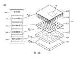
第1圖為根據本揭示內容之部分實施例所繪示的整合式觸控顯示裝置的示意圖。Figure 1 is an integrated diagram according to some embodiments of the present disclosureA schematic diagram of a touch display device.
第2圖為根據本揭示內容之部分實施例所繪示的顯示面板之局部示意圖。FIG. 2 is a partial schematic diagram of a display panel according to some embodiments of the present disclosure.
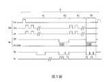
第3圖為本揭示內容之部分實施例中,整合式觸控顯示裝置的時序示意圖。FIG. 3 is a timing diagram of an integrated touch display device in some embodiments of the disclosure.
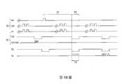
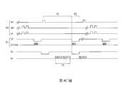
第4A~4E圖為根據本揭示內容之不同實施例,整合式觸控顯示裝置的時序圖。4A~4E are timing diagrams of the integrated touch display device according to different embodiments of the present disclosure.
第5圖為根據本揭示內容之部分實施例的驅動方法流程圖。FIG. 5 is a flowchart of a driving method according to some embodiments of the present disclosure.
以下將以圖式揭露本案之複數個實施方式,為明確說明起見,許多實務上的細節將在以下敘述中一併說明。然而,應瞭解到,這些實務上的細節不應用以限制本案。也就是說,在本揭示內容部分實施方式中,這些實務上的細節是非必要的。此外,為簡化圖式起見,一些習知慣用的結構與元件在圖式中將以簡單示意的方式繪示之。In the following, a plurality of embodiments of the case will be disclosed in a diagram. For the sake of clarity, many practical details will be described together in the following description. However, it should be understood that these practical details should not be used to limit the case. That is to say, in some embodiments of the present disclosure, these practical details are unnecessary. In addition, in order to simplify the drawings, some conventional structures and elements will be shown in a simple schematic manner in the drawings.
於本文中,當一元件被稱為「連接」或「耦接」時,可指「電性連接」或「電性耦接」。「連接」或「耦接」亦可用以表示二或多個元件間相互搭配操作或互動。此外,雖然本文中使用「第一」、「第二」、…等用語描述不同元件,該用語僅是用以區別以相同技術用語描述的元件或操作。除非上下文清楚指明,否則該用語並非特別指稱或暗示次序或順位,亦非用以限定本發明。In this article, when an element is referred to as "connected" or "coupled", it can be referred to as "electrically connected" or "electrically coupled." "Connected" or "coupled" can also be used to indicate that two or more components interact or interact with each other. In addition, although terms such as "first", "second", etc. are used herein to describe different elements, the terms are only used to distinguish elements or operations described in the same technical terms. Unless the context clearly dictates, the term does not specifically refer to or imply order or order, nor is it intended to limit the present invention.
請參閱第1圖所示,係根據本揭示內容之部分實施例所繪示之一種整合型觸控顯示裝置100示意圖。整合型觸控顯示裝置100包含顯示面板110、觸控電路120及光感電路130。在本實施例中,顯示面板110用以根據一影像資料,顯示出一顯示畫面。觸控電路120用以偵測使用者之觸控位置。光感電路130用以掃描一指紋辨識區域,以偵測使用者之指紋等生物資訊。其中觸控電路120可以是內嵌式觸控顯示面板(in cell touch display panel)。Please refer to FIG. 1, which is a schematic diagram of an integrated
請搭配第2圖所示,第2圖係根據本揭示內容之部分實施例的顯示面板110局部示意圖。顯示面板110包含複數個資料線DL及複數個掃描線GL。該些資料線DL電性連接於資料驅動單元141,該些掃描線GL電性連接於掃描驅動單元142。在部分實施例中,資料驅動單元141及掃描驅動單元142設於處理電路140中,且處理電路140用以產生顯示驅動訊號Sd。顯示面板110用以根據顯示驅動訊號Sd,在每一幀週期內更新顯示畫面。Please refer to FIG. 2, which is a partial schematic view of the
在部分實施例中,顯示面板110包含第一基板111及第二基板112。觸控電路120設置於顯示面板110之第一基板111上,且電性連接於處理電路140內的觸控偵測單元143,用以根據觸控驅動訊號St執行觸控偵測。光感電路130設置於顯示面板110之第二基板112,且電性連接於處理電路140內之指紋辨識單元144,用以根據光感驅動訊號Sc執行指紋辨識。根據觸控驅動訊號St或/及顯示驅動訊號Sd的致能與否,整合型觸控顯示裝置100能決定是否致能光感驅動訊號Sc,以執行指紋辨識。在部分實施例中,第二基板112可以包含多個光感電路130,光感電路130中具有複數個光感元件,可以根據外界的光線強度產生變化。舉例而言,光感元件可以是受光強度而變化之光學膜,或者是電容式光學層,或者是具有二極體串接之電晶體形成之電容元件等,本揭示內容並不以此為限。In some embodiments, the
如此,由於整合型觸控顯示裝置100能先判斷觸控驅動訊號St與顯示驅動訊號Sd是否被致能,或判斷觸控驅動訊號St與顯示驅動訊號Sd的當前狀態是否會干擾到光感驅動訊號Sc,再根據判斷結果致能光感驅動訊號Sc,因此,可確保觸控偵測單元143在進行觸控偵測時,不會因為其他訊號的干擾造成偵測上的誤差,從而提升了指紋辨識的精準度。In this way, since the integrated
為便於理解本揭示內容之實施方式,在此詳細說明顯示面板110之結構組成如後。請參閱第1~2圖所示,在部分實施例中,第一基板111與第二基板112的材質可以為大體上透明之玻璃或塑膠材質。此外,顯示面板110還包含驅動層113及液晶層114。驅動層113及液晶層114係位於第一基板111及第二基板112之間。驅動層113上包含複數個以陣列形式排列之畫素電極113a,用以產生電場,以改變液晶層114中液晶的偏轉角度。在部分實施例中,觸控電路120包括複數個觸控感測電極,該些觸控感測電極間保持有預定間隔,用以檢測使用者之手部的觸摸,並識別該觸摸對應於顯示面板110上的對應座標。其中顯示面板110之多個畫素電路所需的電晶體元件係形成於驅動層113,於一實施例中,觸控電路120所需要之元件係與畫素電路之元件共同形成於驅動層113上,觸控電路120所需之元件可以包含有電晶體及電容等,本揭示內容並不以此為限。To facilitate understanding of the embodiments of the present disclosure, the structural composition of the
在部分實施例中,資料驅動單元141、掃描驅動單元142、觸控偵測單元143及指紋辨識單元144可為整合型觸控顯示裝置100內的整合型晶片。In some embodiments, the
在部分實施例中,如第2圖所示,處理電路140能根據觸控驅動訊號St及顯示驅動訊號Sd先產生同步訊號Sy,如此,指紋辨識單元144即可根據同步訊號Sy,得知觸控驅動訊號St及顯示驅動訊號Sd之即時狀態,並選擇致能或禁能光感驅動訊號Sc。舉例而言,如第2圖所示,觸控偵測單元143及指紋辨識單元144可被實施為第二基板112上之第一控制器112a及第二控制器112b,用以產生觸控驅動訊號St及光感驅動訊號Sc(如:第一控制器112a用以產生「垂直方向」觸控驅動訊號St及光感驅動訊號Sc,第二控制器112b則用以產生「水平方向」觸控驅動訊號St及光感驅動訊號Sc)。資料驅動單元141或掃描驅動單元142能將顯示驅動訊號Sd傳遞給第二控制器112b,以確認顯示驅動訊號Sd之當前狀態,同時,第二控制器112b能一併確認觸控驅動訊號St之當前狀態,以產生同步訊號Sy,進而判斷是否適合致能光感驅動訊號Sc。在部分實施例中,觸控偵測單元143、指紋辨識單元144、第一控制器112a及第二控制器112b可被整合在同一個控制裝置內(如第1圖所示之處理電路)。In some embodiments, as shown in FIG. 2, the
請參閱第1~3圖所示,其中第3圖為本揭示內容之部分實施例中,整合型觸控顯示裝置100的時序圖。在部分實施例中,顯示面板110在一幀週期F內更新顯示畫面。幀週期F包含至少一次的顯示期間P1及觸控期間P2。顯示面板110係在顯示期間P1時更新顯示畫面,觸控電路120則在觸控期間P2時執行觸控偵測。在其他部分實施例中,顯示期間P1及觸控期間P2可為複數個,亦即,顯示面板110可分段更新畫面或分段執行觸控偵測。如第3圖所示,在部分實施例中,顯示驅動訊號Sd包含開始訊號stv、時脈訊號ckv及致能訊號oe。觸控驅動訊號St包含觸控訊號TP及電極訊號VCOM。開始訊號stv為每一幀週期F的起始同步訊號,用以作為致能幀週期F的通知訊號之功能。時脈訊號ckv用以當掃描驅動單元142致能時,使顯示面板110據以驅動掃描線GL,在幀週期F內反覆具有高低位準之交流訊號。致能訊號oe為資料驅動單元141致能時之同步訊號,在幀週期F內反覆具有高低位準之交流訊號。觸控訊號TP用以致能觸控電路120,在本實施例中,觸控訊號TP為低電位時,觸控電路120據以執行觸控檢測。電極訊號VCOM在幀週期F內反覆具有高低位準之交流訊號,使觸控電路120據以依序偵測每個觸控感測電極的當前狀態(例如:電容變化)。由於本領域人士能理解觸控面板的顯示原理及觸控原理,故在此即不贅述顯示驅動訊號Sd、觸控驅動訊號St之運作細節。Please refer to FIGS. 1 to 3, where FIG. 3 is a timing diagram of the integrated
在部分實施例中,整合型觸控顯示裝置100選擇在複數個幀週期F中的其中一個幀週期F來執行指紋辨識。在部分實施例中,當顯示驅動訊號Sd或觸控驅動訊號St處於致能準位時,指紋辨識單元144將會禁能光感驅動訊號Sc,避免禁能光感驅動訊號Sc受到干擾。根據不同的驅動方式,辨識期間P3可位於觸控期間P1或觸控期間P2,詳情將於後文詳述。In some embodiments, the integrated
在此以第4A~4E圖為例,說明本揭示內容的各種驅動方法如後。請參閱第4A圖所示,在部分實施例中,整合型觸控顯示裝置100係選擇其中一個幀週期F,並在此一幀週期F中,停止更新顯示畫面及停止觸控偵測,以避免顯示驅動訊號Sd或觸控驅動訊號St干擾到光感驅動訊號Sc。如第4A圖所示,在幀週期F中,資料驅動單元141及掃描驅動單元142禁能顯示驅動訊號Sd,且觸控偵測單元143禁能該觸控驅動訊號St。此時,同步訊號Sy將可於此一幀週期F中出現一致能準位(如:低電壓準位),以表示此一幀週期F中可進行指紋辨識。亦即,指紋辨識單元144可於此一幀週期F中的任何時刻進行指紋辨識。Here, taking FIGS. 4A to 4E as an example, various driving methods of the disclosure are described as follows. Please refer to FIG. 4A. In some embodiments, the integrated
在部分實施例中,整合型觸控顯示裝置100選擇其中一個幀週期F,並在此一幀週期F中,停止執行觸控偵測,以便於觸控期間P2中進行指紋辨識。如第4B圖所示,於觸控期間P2內,觸控偵測單元143禁能觸控驅動訊號St,使指紋辨識單元144於觸控期間P2致能光感驅動訊號Sc。亦即,指紋辨識單元144可於此一幀週期F中觸控期間P2內的任何時刻進行指紋辨識。In some embodiments, the integrated
在部分實施例中,整合型觸控顯示裝置100選擇其中一個幀週期F,並在此一幀週期F中,停止更新顯示畫面,以便於顯示期間P1中進行指紋辨識。由於一幀週期F的時間極短,因此顯示畫面的顯示效果並不會因此降低。如第4C圖所示,在顯示期間P1內,資料驅動單元141及掃描驅動單元142禁能顯示驅動訊號Sd,使指紋辨識單元144於顯示期間P1致能光感驅動訊號Sc。亦即,指紋辨識單元144可於此一幀週期F中顯示期間P1內的任何時刻進行指紋辨識。In some embodiments, the integrated
在部分實施例中,整合型觸控顯示裝置100選擇其中一個幀週期F,並在此一幀週期F的觸控期間P2內進行指紋辨識。由於觸控偵測單元143係依序掃描顯示畫面上的不同位置,以偵測使用者的手部位置,因此,只要指紋辨識區域能避開觸控電路120之偵測區域,光感驅動訊號Sc即不會受到干擾。請參閱第1及4D圖所示,其中ckv_w係觸控偵測單元143發送之時脈訊號,用以與觸控驅動訊號St相搭配。指紋辨識單元144在觸控期間P2內致能光感驅動訊號Sc。處理電路140能判斷觸控電路120當前偵測之偵測區域,以產生同步訊號Sy,當觸控電路120之偵測區域對應於指紋辨識區域時,同步訊號Sy為高電壓準位,指紋辨識單元144會暫時禁能光感驅動訊號Sc。當觸控電路120之偵測區域並未對應於指紋辨識區域時,同步訊號Sy為低電壓準位,此時指紋辨識單元144致能光感驅動訊號Sc。In some embodiments, the integrated
在部分實施例中,整合型觸控顯示裝置100選擇其中一個幀週期F,並在此一幀週期F的顯示期間P1內進行指紋辨識。由於在顯示期間P1時,顯示面板110係依序驅動每一列的畫素電極113,因此,只要顯示面板110當前的驅動區域避開觸控電路120之偵測區域,光感驅動訊號Sc即不會受到干擾。如第4E圖所示,指紋辨識單元144係在顯示期間P1內致能光感驅動訊號Sc。處理電路140能判斷顯示面板110當前驅動之驅動區域,當顯示面板110之驅動區域對應於指紋辨識區域時,同步訊號Sy係被控制於低電壓準位,且指紋辨識單元144禁能該光感驅動訊號Sc。當顯示面板110之驅動區域並未對應於指紋辨識區域時,同步訊號係被控制於高電壓準位,且指紋辨識單元144致能光感驅動訊號Sc。In some embodiments, the integrated
在部分實施例中,整合型觸控顯示裝置還可以包含背光元件150。背光元件150係設置於整合型觸控顯示裝置100中對應於顯示面板110之位置,例如:設於第一基板111之下方,在指紋辨識單元144致能光感驅動訊號Sc前,處理電路140會先傳送增強訊號Se給背光元件150,使背光元件150根據增強訊號Se對指紋辨識區域130a投射背光光線。如此,能確保指紋辨識單元144能清楚地辨識使用者之指紋。In some embodiments, the integrated touch display device may further include a
請參閱第5圖所示,係本揭示內容之部分實施例中,整合型觸控顯示裝置100的驅動方法。驅動方法包括下列步驟:首先,在步驟S01中,顯示面板110根據顯示驅動訊號Sd更新顯示畫面,且觸控電路120根據觸控驅動訊號St進行觸控偵測。在步驟S02中,處理電路140根據觸控驅動訊號St及顯示驅動訊號Sd的當前狀態,產生同步訊號Sy。Please refer to FIG. 5, which is a driving method of the integrated
接著,在步驟S03中,指紋辨識單元144根據同步訊號Sy致能光感驅動訊號Sc,以掃描顯示面板110上之指紋辨識區域。在步驟S04中,處理電路140判斷顯示驅動訊號Sd或觸控驅動訊號St是否處於致能準位?若是,則在步驟S05中,指紋辨識單元144將禁能光感驅動訊號Sc;若否,則回到步驟S03,以完成指紋掃描。Next, in step S03, the
如第4A~4E圖之實施例所述,在部分實施例中,整合型觸控顯示裝置100之驅動方法包含至少五種致能光感驅動訊號Sc的方式。As described in the embodiments of FIGS. 4A to 4E, in some embodiments, the driving method of the integrated
第一種實施例係使光感驅動訊號Sc完全避開顯示驅動訊號Sd或觸控驅動訊號St。亦即,在部分實施例中,處理電路140於一幀週期F中禁能顯示驅動訊號Sd及觸控驅動訊號St,同時在幀週期F中,致能光感驅動訊號Sc。The first embodiment makes the light-sensitive driving signal Sc completely avoid the display driving signal Sd or the touch driving signal St. That is, in some embodiments, the
第二種實施例係使光感驅動訊號Sc完全避開觸控驅動訊號St。亦即,在部分實施例中,處理電路140於一觸控期間P2內禁能觸控驅動訊號St,且於觸控期間P2內致能光感驅動訊號Sc。The second embodiment makes the light-sensitive driving signal Sc completely avoid the touch driving signal St. That is, in some embodiments, the
第三種實施例係使光感驅動訊號Sc完全避開顯示驅動訊號Sd。亦即,在部分實施例中,處理電路140於一顯示期間P1內禁能顯示驅動訊號Sd,且於顯示期間P1致能光感驅動訊號Sc。The third embodiment makes the light-sensitive driving signal Sc completely avoid the display driving signal Sd. That is, in some embodiments, the
第四種實施例係使光感驅動訊號Sc選擇性地避開觸控驅動訊號St。亦即,在部分實施例中,處理電路140於觸控期間P2內致能光感驅動訊號Sc。同時,處理電路140將判斷觸控電路120之偵測區域是否對應於光感電路130之指紋辨識區域?若是,則禁能光感驅動訊號Sc。The fourth embodiment makes the light-sensitive driving signal Sc selectively avoid the touch driving signal St. That is, in some embodiments, the
第五種實施例係使光感驅動訊號Sc選擇性地避開顯示驅動訊號Sd。亦即,在部分實施例中,處理電路140於顯示期間P1內致能光感驅動訊號Sc。同時,處理電路140能判斷顯示面板110之驅動區域是否對應於指紋辨識區域?若是,則禁能光感驅動訊號Sc。The fifth embodiment makes the light-sensitive driving signal Sc selectively avoid the display driving signal Sd. That is, in some embodiments, the
在本揭示內容之各實施例中,處理電路140能根據觸控驅動訊號St及顯示驅動訊號Sd的當前狀態產生同步訊號Sy,使指紋辨識單元144致能或禁能光感訓號。而根據不同的實施方式,處理電路140能選擇在顯示期間P1或觸控期間P2進行指紋掃描,並使光感電路130避開觸控驅動訊號St及顯示驅動訊號Sd的干擾,因此,整合型觸控顯示裝置100的指紋掃描精確度將能因此大幅提昇。In the embodiments of the present disclosure, the
雖然本揭示內容已以實施方式揭露如上,然其並非用以限定本發明內容,任何熟習此技藝者,在不脫離本發明內容之精神和範圍內,當可作各種更動與潤飾,因此本發明內容之保護範圍當視後附之申請專利範圍所界定者為準。Although the present disclosure has been disclosed as above by way of implementation, it is not intended to limit the content of the present invention. Anyone who is familiar with this skill can make various changes and modifications within the spirit and scope of the present content, so the present invention The protection scope of the content shall be deemed as defined by the scope of the attached patent application.
100‧‧‧整合型觸控顯示裝置100‧‧‧Integrated touch display device
110‧‧‧顯示面板110‧‧‧Display panel
111‧‧‧第一基板111‧‧‧The first substrate
112‧‧‧第二基板112‧‧‧Second substrate
113‧‧‧驅動層113‧‧‧Drive layer
113a‧‧‧畫素電極113a‧‧‧Pixel electrode
114‧‧‧液晶層114‧‧‧Liquid crystal layer
120‧‧‧觸控電路120‧‧‧Touch circuit
130‧‧‧光感電路130‧‧‧Light sensing circuit
140‧‧‧處理電路140‧‧‧ processing circuit
141‧‧‧資料驅動單元141‧‧‧Data drive unit
142‧‧‧掃描驅動單元142‧‧‧ Scan drive unit
143‧‧‧觸控偵測單元143‧‧‧Touch detection unit
144‧‧‧指紋辨識單元144‧‧‧fingerprint identification unit
150‧‧‧背光元件150‧‧‧Backlight components
Sc‧‧‧光感驅動訊號Sc‧‧‧Light drive signal
Sd‧‧‧顯示驅動訊號Sd‧‧‧Display drive signal
St‧‧‧觸控驅動訊號St‧‧‧Touch drive signal
Se‧‧‧增強訊號Se‧‧‧Enhanced signal
Claims (15)
Translated fromChinesePriority Applications (2)
| Application Number | Priority Date | Filing Date | Title |
|---|---|---|---|
| TW107141320ATWI686735B (en) | 2018-11-20 | 2018-11-20 | Integrated touch display device and driving method thereof |
| CN201811608309.3ACN109685020B (en) | 2018-11-20 | 2018-12-27 | Integrated touch display device and driving method thereof |
Applications Claiming Priority (1)
| Application Number | Priority Date | Filing Date | Title |
|---|---|---|---|
| TW107141320ATWI686735B (en) | 2018-11-20 | 2018-11-20 | Integrated touch display device and driving method thereof |
Publications (2)
| Publication Number | Publication Date |
|---|---|
| TWI686735Btrue TWI686735B (en) | 2020-03-01 |
| TW202020638A TW202020638A (en) | 2020-06-01 |
Family
ID=66188502
Family Applications (1)
| Application Number | Title | Priority Date | Filing Date |
|---|---|---|---|
| TW107141320ATWI686735B (en) | 2018-11-20 | 2018-11-20 | Integrated touch display device and driving method thereof |
Country Status (2)
| Country | Link |
|---|---|
| CN (1) | CN109685020B (en) |
| TW (1) | TWI686735B (en) |
Families Citing this family (6)
| Publication number | Priority date | Publication date | Assignee | Title |
|---|---|---|---|---|
| KR20220145904A (en)* | 2020-04-29 | 2022-10-31 | 에지스 테크놀러지 인코포레이티드 | Electronic device with fingerprint detection function |
| TWM615933U (en) | 2020-07-21 | 2021-08-21 | 神亞科技股份有限公司 | Fingerprint sensing device |
| CN114093329B (en)* | 2020-07-31 | 2023-05-23 | 京东方科技集团股份有限公司 | Driving method and driving device of display panel and display device |
| CN112051941B (en)* | 2020-09-28 | 2023-12-12 | 京东方科技集团股份有限公司 | Method, circuit and device for synchronizing touch signals during on-screen fingerprint identification |
| CN112363642B (en)* | 2020-12-08 | 2023-10-17 | 深圳市华星光电半导体显示技术有限公司 | Light-sensitive display circuit and display panel |
| TWI819527B (en)* | 2021-05-20 | 2023-10-21 | 元太科技工業股份有限公司 | Display device and display device driving method |
Citations (5)
| Publication number | Priority date | Publication date | Assignee | Title |
|---|---|---|---|---|
| CN104850292A (en)* | 2015-06-01 | 2015-08-19 | 京东方科技集团股份有限公司 | Embedded touch screen, driving method of embedded touch screen and display device |
| US20160132176A1 (en)* | 2014-11-12 | 2016-05-12 | Crucialtec Co., Ltd. | Display Apparatus Capable of Image Scanning and Driving Method Thereof |
| TW201723783A (en)* | 2015-12-18 | 2017-07-01 | 麥克思商務咨詢(深圳)有限公司 | Fingerprint recognizing device and methods |
| US20170351364A1 (en)* | 2014-11-12 | 2017-12-07 | Crucialtec Co., Ltd. | Method of Driving Display Device Capable of Scanning Image |
| TW201837780A (en)* | 2017-03-29 | 2018-10-16 | 大陸商上海耕岩智能科技有限公司 | Fingerprint recognition-based synchronous application starting method and device |
Family Cites Families (17)
| Publication number | Priority date | Publication date | Assignee | Title |
|---|---|---|---|---|
| JP2003280759A (en)* | 2002-03-26 | 2003-10-02 | Gunze Ltd | Information terminal unit with individual authentication function |
| TWI370399B (en)* | 2007-07-18 | 2012-08-11 | Quanta Comp Inc | Electronic apparatus equipped with touch panel capable of identifying fingerprint |
| CN102645999B (en)* | 2012-03-02 | 2015-10-28 | 华映光电股份有限公司 | Touch control display apparatus |
| CN103177683B (en)* | 2013-04-02 | 2016-02-03 | 华映视讯(吴江)有限公司 | Display device and displaying panel driving method thereof |
| CN105824449B (en)* | 2015-01-09 | 2019-11-05 | 南京瀚宇彩欣科技有限责任公司 | Touch control display apparatus and its driving method |
| TWI601301B (en)* | 2015-07-31 | 2017-10-01 | 友達光電股份有限公司 | Optical detecting device and manufacturing method thereof |
| CN105139793A (en)* | 2015-08-28 | 2015-12-09 | 京东方科技集团股份有限公司 | Array substrate, driving method therefor, display panel, and display device |
| TWI591548B (en)* | 2016-04-12 | 2017-07-11 | 友達光電股份有限公司 | Fingerprint detector |
| KR102526290B1 (en)* | 2016-05-30 | 2023-04-28 | 엘지디스플레이 주식회사 | Display device having sensor screen and driving method thereof |
| WO2018049639A1 (en)* | 2016-09-17 | 2018-03-22 | 深圳市汇顶科技股份有限公司 | Pressure detection apparatus and intelligent terminal |
| US10664677B2 (en)* | 2016-12-16 | 2020-05-26 | Lg Display Co., Ltd. | Display device, display panel, fingerprint-sensing method, and circuit for sensing fingerprint |
| WO2018119566A1 (en)* | 2016-12-26 | 2018-07-05 | 深圳市汇顶科技股份有限公司 | Method and device for guiding fingerprint recognition |
| CN107122116A (en)* | 2017-04-28 | 2017-09-01 | 广东欧珀移动通信有限公司 | Fingerprint recognition region display methods and Related product |
| CN107608549B (en)* | 2017-09-08 | 2020-08-25 | 京东方科技集团股份有限公司 | Induction panel, display device and driving method thereof |
| CN107831945A (en)* | 2017-11-30 | 2018-03-23 | 北京集创北方科技股份有限公司 | Electronic equipment, display system and its integrated control device, safe verification method |
| CN108279803A (en)* | 2018-01-24 | 2018-07-13 | 厦门凌阳华芯科技有限公司 | A kind of touch-control display panel and display device |
| CN108664895B (en)* | 2018-04-12 | 2021-05-14 | 厦门天马微电子有限公司 | Display device and fingerprint identification method thereof |
- 2018
- 2018-11-20TWTW107141320Apatent/TWI686735B/enactive
- 2018-12-27CNCN201811608309.3Apatent/CN109685020B/enactiveActive
Patent Citations (6)
| Publication number | Priority date | Publication date | Assignee | Title |
|---|---|---|---|---|
| US20160132176A1 (en)* | 2014-11-12 | 2016-05-12 | Crucialtec Co., Ltd. | Display Apparatus Capable of Image Scanning and Driving Method Thereof |
| US20170351364A1 (en)* | 2014-11-12 | 2017-12-07 | Crucialtec Co., Ltd. | Method of Driving Display Device Capable of Scanning Image |
| CN104850292A (en)* | 2015-06-01 | 2015-08-19 | 京东方科技集团股份有限公司 | Embedded touch screen, driving method of embedded touch screen and display device |
| CN104850292B (en) | 2015-06-01 | 2017-09-29 | 京东方科技集团股份有限公司 | A kind of In-cell touch panel, its driving method and display device |
| TW201723783A (en)* | 2015-12-18 | 2017-07-01 | 麥克思商務咨詢(深圳)有限公司 | Fingerprint recognizing device and methods |
| TW201837780A (en)* | 2017-03-29 | 2018-10-16 | 大陸商上海耕岩智能科技有限公司 | Fingerprint recognition-based synchronous application starting method and device |
Also Published As
| Publication number | Publication date |
|---|---|
| TW202020638A (en) | 2020-06-01 |
| CN109685020A (en) | 2019-04-26 |
| CN109685020B (en) | 2021-03-09 |
Similar Documents
| Publication | Publication Date | Title |
|---|---|---|
| TWI686735B (en) | Integrated touch display device and driving method thereof | |
| US9489076B2 (en) | Touch sensitive display device having auxiliary lines supplying an auxiliary drive signal | |
| JP5665957B2 (en) | Touch screen integrated display | |
| US9507460B2 (en) | Touch sensing device, touch sensing circuit, data driving circuit, and display device driving method | |
| KR101319340B1 (en) | Liquid Crystal Display Device | |
| US9058072B2 (en) | Touch sensing apparatus and driving method thereof | |
| US9870075B2 (en) | Touch screen device | |
| KR101374104B1 (en) | Display apparatus having multi-touch recognizing function and driving method thereof | |
| US9081435B2 (en) | Display apparatus | |
| CN106933410A (en) | Display device | |
| CN105390093A (en) | Organic light emitting display device with touch sensing function | |
| KR20100000409A (en) | Liquid crystal display device | |
| CN104036736A (en) | Driver Ic And Display-input Device | |
| US20190163322A1 (en) | Touch sensing device and image display device using the same | |
| KR20160093750A (en) | Touch screen display device including fingerprint sensor | |
| US9524697B2 (en) | Capacitive touch screen display system including circuitry to address display perturbations induced by panel sensing | |
| KR102440812B1 (en) | Touch sensing device and driving method thereof | |
| CN104076984A (en) | Embedded touch display screen, drive display method thereof and display device | |
| KR101495347B1 (en) | Liquid crystal display | |
| KR101723879B1 (en) | Display device with integrated touch screen | |
| KR101773971B1 (en) | Touch sensing device and method for transmitting data therefrom | |
| JP4788232B2 (en) | Display device and display method | |
| KR102506658B1 (en) | Touch screen device and its driving method | |
| KR101717903B1 (en) | Panel driving circuit | |
| KR20200054424A (en) | A touch implement method using display device |