Movatterモバイル変換


[0]ホーム

URL:


TWI683733B - Driving tool - Google Patents

Driving tool
Download PDF

Info

Publication number
TWI683733B
TWI683733BTW103128950ATW103128950ATWI683733BTW I683733 BTWI683733 BTW I683733BTW 103128950 ATW103128950 ATW 103128950ATW 103128950 ATW103128950 ATW 103128950ATW I683733 BTWI683733 BTW I683733B
Authority
TW
Taiwan
Prior art keywords
push rod
contact
unit
compressed air
housing
Prior art date
Application number
TW103128950A
Other languages
Chinese (zh)
Other versions
TW201527054A (en
Inventor
石澤禎紀
大內治彥
Original Assignee
日商工機控股股份有限公司
Priority date (The priority date is an assumption and is not a legal conclusion. Google has not performed a legal analysis and makes no representation as to the accuracy of the date listed.)
Filing date
Publication date
Application filed by 日商工機控股股份有限公司filedCritical日商工機控股股份有限公司
Publication of TW201527054ApublicationCriticalpatent/TW201527054A/en
Application grantedgrantedCritical
Publication of TWI683733BpublicationCriticalpatent/TWI683733B/en

Links

Images

Classifications

Landscapes

Abstract

In a driving tool, a push lever plunger is moved upward by a push lever unit when the push lever unit is disposed at an uppermost position. The push lever unit includes a first protruding part and a second protruding part. The first protruding part is configured to contact a first contact part of a housing when the push lever unit is disposed at the uppermost position. The second protruding part is configured to contact a second contact part of the housing when the push lever unit is disposed at the uppermost position. A compressed air control unit, the second protruding part, and an ejection channel are disposed within an imaginary plane extending in an approximate vertical direction. The compressed air control unit is disposed on a side opposite to the second protruding part with respect to the ejection channel in a horizontal direction.

Description

Translated fromChinese
驅動工具Drive tool

本發明係有關於一種諸如打釘工具(nail-driving tool)之類的驅動工具,它使用壓縮空氣,將扣件(fasteners)驅動至工件中。The present invention relates to a driving tool such as a nail-driving tool that uses compressed air to drive fasteners into a workpiece.

在此項技藝中已知有使用壓縮空氣將釘子驅動至工件中之打釘工具。一些打釘工具被設計成以快速連續方式來實施打釘操作。日本未審查專利申請案公開第2012-111017號顯示了此類型之打釘工具。In this art, there are known nailing tools that use compressed air to drive nails into a workpiece. Some nailing tools are designed to perform nailing operations in a fast and continuous manner. Japanese Unexamined Patent Application Publication No. 2012-111017 shows this type of nailing tool.

一種可理解的打釘工具,具有推桿及推桿柱塞,其中當該推桿向上移動時,便啟動該推桿柱塞。然而,會因推桿之鬆弛或磨損而使推桿傾斜。推桿之傾斜造成這樣的問題:推桿被向上移動之同時,推桿無法接觸推桿柱塞。當推桿變成鬆弛或磨損且無法適當地啟動推桿柱塞時,此打釘工具可能無法適當地工作。換句話說,很難生產一種在推桿變成鬆弛或磨損後仍可持續使用的驅動工具。An understandable nailing tool has a push rod and a push rod plunger, wherein when the push rod moves upward, the push rod plunger is activated. However, the push rod may tilt due to slack or wear of the push rod. The tilt of the push rod causes such a problem that the push rod cannot contact the push rod plunger while being moved upward. When the push rod becomes loose or worn and the push rod plunger cannot be properly activated, the nailing tool may not work properly. In other words, it is difficult to produce a driving tool that can be used continuously after the push rod becomes slack or worn.

再者,該推桿通常是由複數個組裝在一起之零件所構成。這些零件本身可能因它們的尺寸的變動及用以將它們連接在一起之手段,而造成鬆弛不合。這樣的鬆弛亦可能造成推桿之傾斜。Moreover, the push rod is usually composed of a plurality of parts assembled together. These parts themselves may cause slack due to changes in their dimensions and the means used to connect them together. Such slack may also cause tilting of the putter.

當使推桿重複地做垂直往復運動時,推桿滑座亦易傾向於磨損,而且,此磨損可能進一步增加它的組件之鬆弛。推桿亦可能隨時間而變形。因此,當此打釘工具之使用已持續很久,上述問題會變得特別明顯。When the push rod is repeatedly reciprocated vertically, the push rod slide is also easy to tiltTo wear, and this wear may further increase the slack of its components. The putter may also deform over time. Therefore, when the use of this nailing tool has been going on for a long time, the above problems will become particularly obvious.

有鑑於前面所述,本發明之目的為提供一種具有解決上述問題之結構的驅動工具。In view of the foregoing, the object of the present invention is to provide a driving tool having a structure that solves the above problems.

為了達到上述及其它目的,本發明提供一種驅動工具,其可以包括:外殼、推桿單元、壓縮空氣控制單元、及驅動單元。該外殼可以具有鼻端,此鼻端係固定至該外殼且設置有用以導引扣件之彈射通道。該彈射通道可以被界定在該鼻端內側且朝垂直方向延伸。該推桿單元可以配置成相對於該外殼而朝垂直方向在一個最下面位置與一個最上面位置之間移動。該壓縮空氣控制單元可以配置成用以控制壓縮空氣之供應,且包括一推桿柱塞。該推桿柱塞可以配置成向上及向下移動。當該推桿單元係位處在最上面位置時,該推桿單元可以使該推桿柱塞向上移動。該驅動單元可以配置成在接收該壓縮空氣控制單元所供應的壓縮空氣時,將扣件驅動至工件中。該外殼可以包括第一接觸部位及第二接觸部位。該推桿單元可以包括第一突出部位及第二突出部位。該第一突出部位可以配置成當該推桿單元位處在最上面位置時,接觸到該第一接觸部位。該第二突出部位可以配置成當該推桿單元位處在最上面位置時,接觸到該第二接觸部位。該壓縮空氣控制單元、該第二突出部位、及該彈射通道,可以位處在一個以逼近垂直方向延伸的假想平面上。該壓縮空氣控制單元可以在水平方向上相對於該彈射通道位處在第二突出部位之對面一側上。In order to achieve the above and other objects, the present invention provides a driving tool, which may include: a housing, a push rod unit, a compressed air control unit, and a driving unit. The casing may have a nose end which is fixed to the casing and provided with an ejection channel for guiding the fastener. The ejection channel may be defined inside the nose end and extend in a vertical direction. The pusher unit may be configured to move vertically between a lowermost position and an uppermost position relative to the housing. The compressed air control unit may be configured to control the supply of compressed air and include a push rod plunger. The push rod plunger can be configured to move up and down. When the push rod unit is in the uppermost position, the push rod unit can move the push rod plunger upward. The driving unit may be configured to drive the fastener into the workpiece when receiving the compressed air supplied by the compressed air control unit. The housing may include a first contact location and a second contact location. The push rod unit may include a first protruding part and a second protruding part. The first protruding portion may be configured to contact the first contact portion when the push rod unit is at the uppermost position. The second protruding portion may be configured to contact the second contact portion when the push rod unit is at the uppermost position. The compressed air control unit, the second protruding part, and the ejection channel may be located on an imaginary plane extending in a direction approaching the vertical direction. The compressed air control unit may be located on the side opposite to the second protrusion in the horizontal direction with respect to the ejection passage.

較佳地,當該推桿單元從最下面位置移動至最上面位置之同時,該第二突出部位可以配置成在該第一突出部位接觸到該第一接觸部位之前,接觸到該第二接觸部位。Preferably, while the pusher unit moves from the lowermost position to the uppermost position, the second protruding part may be configured to contact the second contact before the first protruding part contacts the first contacting part Location.

較佳地,該第二接觸部位可以具有一個斜面。此斜面可以定位在一個遠離於該彈射通道的位置上,且向下突出。Preferably, the second contact portion may have a slope. The inclined surface can be positioned at a position away from the ejection channel and protrudes downward.

較佳地,該第二接觸部位可以具有一個斜面,而此斜面之法線係導向該鼻端。Preferably, the second contact portion may have a slope, and the normal of the slope is directed to the nose.

較佳地,該驅動工具可以進一步包括一個在該外殼上所設置的板機桿。較佳地,當操作該板機桿時,可以向上推動該推桿柱塞。該壓縮空氣控制單元可以供應壓縮空氣,而且,該驅動單元可以使用已供應的壓縮空氣,將扣件驅動至工件中。Preferably, the driving tool may further include a trigger lever provided on the housing. Preferably, when the trigger lever is operated, the push rod plunger can be pushed upward. The compressed air control unit can supply compressed air, and the drive unit can use the supplied compressed air to drive the fastener into the workpiece.

依據另一態樣,本發明提供一種驅動工具,其可以包括:外殼、鼻端、驅動葉片、驅動機構、板機桿、及推桿單元。該外殼可以具有固定至該外殼且設置有用以導引扣件的彈射通道的鼻端。該彈射通道可以位處在該鼻端內側且朝垂直方向延伸。該鼻端可以具有一個下端部位。該驅動葉片可以配置成用以在該彈射通道中往復運動並驅動扣件。該驅動機構可以位處在該外殼中,且配置成用以驅動該驅動葉片。該板機桿可以設置在該外殼上。該推桿單元可以配置成相對於該鼻端而朝垂直方向向上及向下移動。該推桿單元可以具有:下端部分,位處在一個較靠近該鼻端之下端部位而非該板機桿的位置上;上端部分,位處在一個較靠近該板機桿而非該鼻端之下端部位的位置上;以及,接觸部位,配置成接觸於該外殼。該接觸部位可以在水平方向上相對於該彈射通道位處在該上端部分之對面一側上。該下端部分、該上端部分、及該接觸部位,可以位處在單一的假想平面上。According to another aspect, the present invention provides a driving tool, which may include: a housing, a nose, a driving blade, a driving mechanism, a trigger lever, and a push rod unit. The housing may have a nose fixed to the housing and provided with an ejection channel to guide the fastener. The ejection channel may be located inside the nose and extend vertically. The nose can have a lower end. The driving blade may be configured to reciprocate and drive the fastener in the ejection channel. The driving mechanism may be located in the housing and configured to drive the driving blade. The trigger lever can be arranged on the housing. The push rod unit may be configured to move upward and downward in a vertical direction relative to the nose. The push rod unit may have: a lower end portion located at a position closer to the lower end portion of the nose end than the trigger lever; an upper end portion located at a position closer to the trigger lever than the nose end The position of the lower end portion; and, the contact portion is configured to contact the housing. The contact portion may be located on the side opposite to the upper end portion with respect to the ejection passage position in the horizontal direction. The lower end portion, the upper end portion, and the contact portion,It can be located on a single imaginary plane.

在假設鼻端係定位在外殼下方、及驅動葉片係朝垂直方向延伸的情況下,使用該等術語「垂直」、「水平」、「最下面」、「最上面」、「向上」、「向下」、「上」及「下」。Under the assumption that the nose end system is positioned below the casing and the drive blade system extends vertically, the terms "vertical", "horizontal", "bottom", "topmost", "upward", and "direction" are used "Down", "up" and "down".

本發明之特別形體及優點以及其它目的,從下面配合所附圖式所做之描述,將得以明瞭。The special shape, advantages and other objects of the present invention will be apparent from the following description made in conjunction with the accompanying drawings.

10‧‧‧汽缸;驅動機構10‧‧‧ cylinder; drive mechanism

11‧‧‧外殼11‧‧‧Housing

12‧‧‧活塞;驅動機構12‧‧‧piston; drive mechanism

13‧‧‧驅動葉片;驅動單元13‧‧‧Drive blade; drive unit

13a‧‧‧葉尖13a‧‧‧Yijian

14‧‧‧鼻端14‧‧‧ Nose

14A‧‧‧鼻尖;下端部位14A‧‧‧tip of nose; lower part

14B‧‧‧彈射孔14B‧‧‧Ejection hole

14C‧‧‧彈射通道14C‧‧‧Ejection channel

15‧‧‧推桿單元15‧‧‧Push unit

16‧‧‧板機桿16‧‧‧Board lever

17‧‧‧空氣塞17‧‧‧Air plug

18‧‧‧儲藏室;驅動機構18‧‧‧storage room; drive mechanism

19‧‧‧空氣通道19‧‧‧Air channel

20‧‧‧主閥室20‧‧‧Main valve room

21‧‧‧彈簧21‧‧‧Spring

22‧‧‧排氣閥;驅動機構22‧‧‧ exhaust valve; drive mechanism

23‧‧‧回流室23‧‧‧Reflow room

24‧‧‧空氣通道24‧‧‧Air channel

25‧‧‧氣孔25‧‧‧Blowhole

26‧‧‧止回閥26‧‧‧Check valve

27‧‧‧活塞緩衝器27‧‧‧ Piston buffer

28‧‧‧主閥;驅動機構28‧‧‧Main valve; drive mechanism

29A‧‧‧第一接觸部位29A‧‧‧First contact part

29B‧‧‧第二接觸部位29B‧‧‧Second contact part

29X‧‧‧(第二接觸部位)斜面29X‧‧‧(second contact part) slope

29Y‧‧‧(第二接觸部位)水平面29Y‧‧‧(second contact part) horizontal plane

50‧‧‧壓縮空氣控制單元50‧‧‧Compressed air control unit

51‧‧‧空氣通道51‧‧‧Air channel

52‧‧‧推桿柱塞52‧‧‧Push rod plunger

53‧‧‧板機柱塞53‧‧‧Plug

54‧‧‧板機閥54‧‧‧trigger valve

55‧‧‧閥擋55‧‧‧ Valve stop

60‧‧‧匣盒60‧‧‧Box

61‧‧‧饋送器61‧‧‧Feeder

75‧‧‧推桿單元75‧‧‧Push unit

79A‧‧‧第一接觸部位79A‧‧‧First contact part

79B‧‧‧第二接觸部位79B‧‧‧Second contact part

100‧‧‧打釘工具100‧‧‧ nailing tool

141‧‧‧錨銷141‧‧‧Anchor pin

151‧‧‧推桿體151‧‧‧Push rod body

151A‧‧‧(推桿體)下端部分151A‧‧‧(putter body) lower part

152‧‧‧推桿彈簧152‧‧‧Push rod spring

153‧‧‧調節器153‧‧‧ Regulator

154‧‧‧推桿154‧‧‧Putter

154A‧‧‧第一突出部位;(推桿單元)上端部分154A‧‧‧First protruding part; (push bar unit) upper part

154B‧‧‧第二突出部位;(推桿單元)接觸部位154B‧‧‧Second protruding part; (push bar unit) contact part

155‧‧‧螺栓155‧‧‧bolt

156‧‧‧棒桿156‧‧‧ stick

200‧‧‧打釘工具200‧‧‧ nailing tool

711‧‧‧外殼711‧‧‧Housing

751‧‧‧推桿體751‧‧‧Push rod body

752‧‧‧推桿彈簧752‧‧‧Push rod spring

753‧‧‧調節器753‧‧‧ Regulator

754‧‧‧推桿754‧‧‧Putter

754A‧‧‧第一突出部位754A‧‧‧The first protruding part

754B‧‧‧第二突出部位754B‧‧‧Second protruding part

755‧‧‧螺栓755‧‧‧bolt

756‧‧‧棒桿756‧‧‧stick

A‧‧‧方向A‧‧‧Direction

B‧‧‧方向B‧‧‧ direction

L‧‧‧垂直距離L‧‧‧Vertical distance

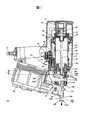
圖1係顯示依據本發明之具體例的驅動工具之結構的剖面圖;圖2係圖1所示之驅動工具之底面圖。FIG. 1 is a cross-sectional view showing the structure of a driving tool according to a specific example of the present invention; FIG. 2 is a bottom view of the driving tool shown in FIG. 1.

圖3概略地描述圖1所示之驅動工具之推桿單元之結構。FIG. 3 schematically describes the structure of the pusher unit of the driving tool shown in FIG. 1. FIG.

圖4係顯示圖1所示之驅動工具之接觸部位之形狀之剖面圖。4 is a cross-sectional view showing the shape of the contact portion of the driving tool shown in FIG. 1.

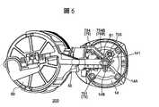
圖5係顯示打釘工具之比較實例的剖面圖。5 is a cross-sectional view showing a comparative example of a nailing tool.

圖6係圖5所示之打釘工具之底面圖。Fig. 6 is a bottom view of the nailing tool shown in Fig. 5.

圖7概略地描述圖5所示之打釘工具之推桿單元之結構。FIG. 7 schematically describes the structure of the pusher unit of the nailing tool shown in FIG. 5. FIG.

將參考圖1至4來描述依據本發明之具體例的驅動工具。在假設此驅動工具係位處在意欲被使用之方位下,在整個說明中使用術語「向上」、「向下」、「上」、「下」、「上方」、「下方」、「右」、「左」等。在使用中,此驅動工具係如圖1所示放置。A driving tool according to a specific example of the present invention will be described with reference to FIGS. 1 to 4. Assuming that the driving tool is in the orientation intended to be used, the terms "up", "down", "up", "down", "up", "down", "right" are used throughout the description , "Left", etc. In use, this drive tool is placed as shown in Figure 1.

將描述一個打釘工具100,作為驅動工具之實例。圖1係顯示此打釘工具100之結構的剖面圖,圖2則係此打釘工具100之底面圖。打釘工具100在圖1中係配置成向下驅動釘子。Anailing tool 100 will be described as an example of the driving tool. Fig1 is a cross-sectional view showing the structure of thenailing tool 100, and FIG. 2 is a bottom view of thenailing tool 100. Thenailing tool 100 is configured to drive nails downward in FIG. 1.

打釘工具100包括:外殼11、汽缸10、活塞12、驅動葉片13、推桿單元15、板機桿16、主閥28、壓縮空氣控制單元50、匣盒60、及饋送器61。外殼11係打釘工具100之本體,且配置成用以支撐並覆蓋住所有的內部零件。Thenailing tool 100 includes ahousing 11, acylinder 10, apiston 12, adriving blade 13, apusher unit 15, atrigger rod 16, amain valve 28, a compressedair control unit 50, acassette 60, and afeeder 61. Thehousing 11 is the body of thenailing tool 100 and is configured to support and cover all internal parts.

外殼11界定出一個配置成用以儲存高壓壓縮空氣的儲藏室18。儲藏室18係設置在汽缸10上方。空氣塞17藉由空氣軟管(未顯示)而連接至儲藏室18。高壓壓縮空氣經由空氣塞17及空氣軟管而被引入至儲藏室18。Thehousing 11 defines astorage chamber 18 configured to store high-pressure compressed air. Thestorage room 18 is provided above thecylinder 10. Theair plug 17 is connected to thestorage compartment 18 by an air hose (not shown). High-pressure compressed air is introduced into thestorage chamber 18 via theair plug 17 and the air hose.

汽缸10係位處在外殼11內側且具有一個朝垂直方向延伸的中心軸線。汽缸10係配置成在外殼11內向上及向下移動。將彈簧21纏繞在汽缸10之外周圍表面上。彈簧21以其一端固定至外殼11而另一端固定至汽缸10。彈簧21推動該汽缸10向上。在汽缸10之下側形成空氣通道24,以允許回流室23與下方室(在汽缸10中之活塞12下面所形成的空間)間之相通。回流室23在外殼11中係形成於汽缸10之周圍。Thecylinder 10 is located inside thecasing 11 and has a central axis extending in the vertical direction. Thecylinder 10 is configured to move upward and downward within thehousing 11. Thespring 21 is wound on the outer peripheral surface of thecylinder 10. Thespring 21 is fixed to thehousing 11 at one end thereof and to thecylinder 10 at the other end. Thespring 21 pushes thecylinder 10 upward. Anair passage 24 is formed below thecylinder 10 to allow communication between thereturn chamber 23 and the lower chamber (the space formed under thepiston 12 in the cylinder 10). Thereturn chamber 23 is formed around thecylinder 10 in thehousing 11.

在汽缸10以一指定高度處形成複數個氣孔25。此等氣孔25係位在比空氣通道24為高的位置處,且間隔地形成於汽缸10之周圍。該等氣孔25允許汽缸10之內部與回流室23間之相通。止回閥26分別耦接至該等氣孔25。此等止回閥26允許空氣從汽缸10之內部只朝一個方向流入回流室23。A plurality ofair holes 25 are formed in thecylinder 10 at a specified height. These air holes 25 are located at a position higher than theair passage 24 and are formed around thecylinder 10 at intervals. The air holes 25 allow communication between the inside of thecylinder 10 and thereturn chamber 23. Thecheck valves 26 are respectively coupled to the air holes 25. Thesecheck valves 26 allow air to flow into thereturn chamber 23 from the inside of thecylinder 10 in only one direction.

活塞12係設置在該汽缸10內側且能在其內垂直地滑動。活塞12將汽缸10內側之空間分隔成上方室及下方室。該上方室係形成於活塞12上方。該下方室則係形成於活塞12下方。活塞12係配置成當壓縮空氣被供應且被注入至汽缸10中之活塞12上方所界定的空間(上方室)時,向下快速地移動。活塞12在一個大於汽缸10之移動範圍的範圍內,在汽缸10內側垂直地移動。在初始狀態中,汽缸10係處於它的上方位置,而且,活塞12係處於它的上死點(top dead center)。Thepiston 12 is arranged inside thecylinder 10 and can slide vertically in it. Thepiston 12 divides the space inside thecylinder 10 into an upper chamber and a lower chamber. The topThe chamber system is formed above thepiston 12. The lower chamber is formed below thepiston 12. Thepiston 12 is configured to quickly move downward when compressed air is supplied and injected into the space (upper chamber) defined above thepiston 12 in thecylinder 10. Thepiston 12 moves vertically inside thecylinder 10 within a range larger than the movement range of thecylinder 10. In the initial state, thecylinder 10 is in its upper position, and thepiston 12 is in its top dead center.

驅動葉片13係設置在活塞12之底部,且配置成在彈射通道14C中往復運動,以驅動釘子。驅動葉片13係與活塞12一體成形,且從那裏向下垂直地延伸。驅動葉片13之下端構成葉尖13a。葉尖13a係配置成當壓縮空氣之壓力使活塞12向下移動並以強的衝擊力向下驅動釘子時,接觸到釘子之頭部。換句話說,該驅動葉片13係配置成在接收從壓縮空氣控制元50所供應的壓縮空氣後,立即將釘子驅動至工件中。驅動葉片13係充當作驅動單元之一個實例。Thedriving blade 13 is disposed at the bottom of thepiston 12, and is configured to reciprocate in theejection channel 14C to drive the nail. Thedriving blade 13 is integrally formed with thepiston 12 and extends vertically downward from there. The lower end of thedriving blade 13 constitutes ablade tip 13a. Theblade tip 13a is configured to contact the head of the nail when the pressure of the compressed air moves thepiston 12 downward and drives the nail downward with a strong impact force. In other words, thedriving blade 13 is configured to drive the nail into the workpiece immediately after receiving the compressed air supplied from the compressedair control element 50. Thedriving blade 13 serves as an example of a driving unit.

外殼11進一步包括鼻端14。特別地,鼻端14係固定至外殼11之主體之底部。鼻端14具有一個稱為鼻尖14A的窄尖端部分。鼻尖14A係充當作該鼻端之下端部位之一個實例。在鼻尖14A之下端中形成有彈射孔14B。用以導引諸如釘子之類的扣件的彈出通道14C,係被界定於鼻尖14A內側且朝垂直方向延伸。錨銷(anchoring pin)141固定至鼻端14之鼻尖14A側。Thehousing 11 further includes anose 14. In particular, thenose 14 is fixed to the bottom of the main body of thehousing 11. Thenose 14 has a narrow tip portion called anose tip 14A. Thetip 14A serves as an example of the lower end of the nose. Anejection hole 14B is formed in the lower end of thenose tip 14A. Theejection channel 14C for guiding a fastener such as a nail is defined inside thenose tip 14A and extends in a vertical direction. Ananchoring pin 141 is fixed to thetip 14A side of thenose end 14.

葉尖13a係配置成用以準確地且不動搖地朝垂直方向沿著鼻端14向下驅動釘子。特別地,驅動葉片13在鼻尖14A中之彈射通道14C內垂直地向下移動。結果,在彈射通道14C中可靠地向下驅動釘子,且使之經由在鼻尖14A之底部中所形成的彈射孔14B彈射出來。Theblade tip 13a is configured to accurately and unwaveringly drive the nail down thenose 14 in the vertical direction. Specifically, thedriving blade 13 vertically moves downward in theejection channel 14C in thetip 14A. As a result, the nail is reliably driven downward in theejection channel 14C and passes through the ejection hole formed in the bottom of thenose tip 14A14B ejected.

在汽缸10之底部中靠近活塞12之下死點處設置有活塞緩衝器27。此活塞緩衝器27係由彈性材料所製成,且在活塞12撞擊釘子之後,用以吸收活塞12所保有的殘餘能量。Apiston bumper 27 is provided in the bottom of thecylinder 10 near the dead center below thepiston 12. Thepiston bumper 27 is made of an elastic material, and is used to absorb the residual energy retained by thepiston 12 after thepiston 12 hits the nail.

在活塞12上方及在外殼11中設置有排氣閥22。此排氣閥22係配置成用以允許及阻擋該上方室(在汽缸10中之活塞12上方的空間)與外部空氣間之通道,且係配置成用以從該上方室排放空氣。Anexhaust valve 22 is provided above thepiston 12 and in thehousing 11. Theexhaust valve 22 is configured to allow and block the passage between the upper chamber (the space above thepiston 12 in the cylinder 10) and outside air, and is configured to exhaust air from the upper chamber.

外殼11進一步界定出內部放置有主閥28的主閥室20。此主閥室20係形成於汽缸10之頂部周圍。主閥28係配置成與稍後所述之板機閥54相聯結地操作。設置有空氣通道19,以便從儲藏室18將空氣引入主閥室20。Thehousing 11 further defines amain valve chamber 20 in which amain valve 28 is placed. Thismain valve chamber 20 is formed around the top of thecylinder 10. Themain valve 28 is configured to operate in conjunction with thetrigger valve 54 described later. Anair passage 19 is provided to introduce air from thestorage chamber 18 into themain valve chamber 20.

板機桿16係設置在外殼11上。更特別地,板機桿16在圖1中係經由一個設置在它右端的軸桿(未顯示)而安裝在外殼11中。板機桿16能繞著此軸桿而旋轉。Thetrigger lever 16 is provided on thehousing 11. More specifically, thetrigger lever 16 is installed in thehousing 11 in FIG. 1 via a shaft (not shown) provided at its right end.Trigger lever 16 can rotate around this shaft.

匣盒60係位處在鼻端14之左側,且配置成用以容納在打釘操作中所使用之釘子。饋送器61係配置成用以在釘子之頭部位在上方的情況下從匣盒60供應該等釘子至彈射通道14C中。Thecassette 60 is located on the left side of thenose 14 and is configured to receive nails used in the nailing operation. Thefeeder 61 is configured to supply the nails from thecassette 60 into theejection channel 14C with the head portion of the nails above.

推桿單元15係安裝在鼻尖14A周圍。推桿單元15係配置成相對於外殼11(鼻端14)朝垂直方向在一個最下面位置與一個最上面位置之間移動,同時,在鼻尖14A之外表面上滑動。Thepush rod unit 15 is installed around thetip 14A. Thepusher unit 15 is configured to move vertically between a lowermost position and an uppermost position relative to the housing 11 (nose end 14), while sliding on the outer surface of thenose tip 14A.

推桿單元15係由已組裝在一起的複數個構件所配置而成,包括:推桿體151、推桿彈簧152、調節器153、推桿154、及螺栓155。Thepush rod unit 15 is configured by a plurality of components assembled together, including: apush rod body 151, apush rod spring 152, anadjuster 153, apush rod 154, and abolt 155.

推桿體151具有整體上圓筒形形狀。推桿體151之下端部分151A覆蓋住鼻尖14A。該下端部分151A係位處在一個較靠近鼻尖14A而非板機桿16的位置。推桿體151係配置成在鼻尖14A之側表面上滑動。推桿體151係夾在錨銷141與鼻尖14A之側表面之間,而在這些零件之間形成有微小間隙,以便推桿體151可在鼻尖14A之側表面上垂直地滑動。當操作員放置鼻尖14A之下端成而與工件相接觸時,推桿單元15(推桿體151)便沿著鼻端14(鼻尖14A)向上移動。Thepush rod body 151 has an overall cylindrical shape. Thelower end portion 151A of thepush rod body 151 covers thenose tip 14A. Thelower end portion 151A is located at a position closer to thetip 14A than thetrigger lever 16. Thepush rod body 151 is configured to slide on the side surface of thenose tip 14A. Thepush rod body 151 is sandwiched between theanchor pin 141 and the side surface of thenose tip 14A, and a slight gap is formed between these parts so that thepush rod body 151 can slide vertically on the side surface of thenose tip 14A. When the operator places the lower end of thenose tip 14A into contact with the workpiece, the push rod unit 15 (push rod body 151) moves upward along the nose tip 14 (nose tip 14A).

推桿彈簧152係配置成向下推動推桿單元15,以致於,當沒有施加外力至推桿體151之下端時(當該推桿體151之底緣沒有與工件或類似者相接觸時),下端部分151A之下端比鼻尖14A之下端向下突出更遠。Thepusher spring 152 is configured to push thepusher unit 15 downward, so that when no external force is applied to the lower end of the pusher body 151 (when the bottom edge of thepusher body 151 is not in contact with the workpiece or the like) The lower end of thelower end portion 151A protrudes further downward than the lower end of thenose tip 14A.

推桿154藉由螺栓155而被固定至推桿體151。推桿154藉由螺栓155而被固定至適當位置。圖1中之推桿154之左上部分朝壓縮空氣控制單元50延伸,使推桿154之上端靠近板機桿16。調節器153被插置於螺栓155之頭部與推桿154之間。調節器153之上方內部具有螺紋,以便與推桿154鎖固在一起。藉由旋轉調節器153,操作員可調整推桿體151與推桿154之相對垂直位置,以便調整釘子之驅動深度。Thepush rod 154 is fixed to thepush rod body 151 bybolts 155. Thepush rod 154 is fixed in place bybolts 155. The upper left portion of thepush rod 154 in FIG. 1 extends toward the compressedair control unit 50 so that the upper end of thepush rod 154 is close to thetrigger rod 16. Theadjuster 153 is interposed between the head of thebolt 155 and thepush rod 154. The upper part of theadjuster 153 is internally threaded so as to be locked with thepush rod 154. By rotating theadjuster 153, the operator can adjust the relative vertical position of thepush rod body 151 and thepush rod 154 in order to adjust the driving depth of the nail.

推桿154在圖1之左側上具有第一突出部位154A,而在圖1之右側上具有第二突出部位154B。第一突出部位154A在一個用於接觸稍後所述之第一接觸部位29A的位置處向上突出。第二突出部位154B則在一個用於接觸稍後所述之第二接觸部位29B的位置處向上突出。第一突出部位154A係位處在一個較靠近板機桿16而非鼻尖14A的位置。第一突出部位154A係充當作推桿單元之上端部分之一個實例。在推桿單元15從其最下面位置移動至最上面位置之同時,第二突出部位154B係配置成在第一突出部位154A接觸於第一接觸部位29A之前,接觸到第二接觸部位29B。第二突出部位154B係充當作推桿單元之接觸部位之一個實例。Thepush rod 154 has a first protrudingportion 154A on the left side of FIG. 1 and a second protrudingportion 154B on the right side of FIG. 1. The first protrudingportion 154A protrudes upward at a position for contacting thefirst contact portion 29A described later. The second protrudingportion 154B protrudes upward at a position for contacting thesecond contact portion 29B described later. The firstprotruding part 154A is located closer to the triggerThe position of therod 16 instead of thetip 14A. The first protrudingportion 154A serves as an example of the upper end portion of the putter unit. While thepusher unit 15 moves from its lowermost position to its uppermost position, the second protrudingportion 154B is configured to contact thesecond contact portion 29B before the first protrudingportion 154A contacts thefirst contact portion 29A. The second protrudingportion 154B serves as an example of a contact portion serving as a push rod unit.

圖3概略地描述圖1之推桿單元15之結構。在圖3中,推桿單元15被顯示為單一的整體單元。注意到,雖然圖3所示之閥擋(valve guard)55(描述於後)、棒桿156(描述於後)、及推桿單元15之形狀被描述成不同於圖1所述之那些零件的形狀,但是,圖3所示之閥擋55、棒桿156、及推桿單元15分別表示圖1所示之那些零件。FIG. 3 schematically describes the structure of thepush rod unit 15 of FIG. In FIG. 3, theputter unit 15 is shown as a single integral unit. Note that although the shapes of the valve guard 55 (described in the back), the rod 156 (described in the back), and thepush rod unit 15 shown in FIG. 3 are described as different from those described in FIG. 1 However, thevalve stop 55, therod 156, and thepush rod unit 15 shown in FIG. 3 represent those parts shown in FIG. 1, respectively.

如圖3所示,第一突出部位154A及第二突出部位154B係位在推桿體151之相對側上。換句話說,第二突出部位154B係在水平方向上相對於彈射通道14C位處在第一突出部位154A之對面一側上。當推桿單元15向上移動時,該第一突出部位154A及第二突出部位154B便定位成接觸於該外殼11。As shown in FIG. 3, the first protrudingportion 154A and the second protrudingportion 154B are located on opposite sides of thepush rod body 151. In other words, the second protrudingportion 154B is located on the side opposite to the first protrudingportion 154A in the horizontal direction with respect to theejection passage 14C. When thepush rod unit 15 moves upward, the first protrudingportion 154A and the second protrudingportion 154B are positioned to contact thehousing 11.

如圖1所示,外殼11進一步包括一個固定至壓縮空氣控制單元50之閥擋55。此閥擋55係配置成用以保護壓縮空氣控制單元50。As shown in FIG. 1, thehousing 11 further includes avalve stop 55 fixed to the compressedair control unit 50. Thevalve stop 55 is configured to protect the compressedair control unit 50.

壓縮空氣控制單元50係沿著汽缸10之一側而設置在外殼11中。特別是,壓縮空氣控制單元50係設置在外殼11之較靠近於匣盒60的一側上。壓縮空氣控制單元50係配置成用以控制壓縮空氣從儲藏室18至該上方室(在汽缸10中之活塞12上方所形成的空間)之供應。換句話說,壓縮空氣控制單元50係配置成用以供應壓縮空氣至主閥室20中。如圖2所示,壓縮空氣控制單元50係位處在一個朝匣盒60之方向遠離於鼻尖14A的位置上(在圖2中沿著水平方向之鼻尖14A之左側)。The compressedair control unit 50 is provided in thecasing 11 along one side of thecylinder 10. In particular, the compressedair control unit 50 is provided on the side of thecasing 11 closer to thecassette 60. The compressedair control unit 50 is configured to control the supply of compressed air from thestorage chamber 18 to the upper chamber (the space formed above thepiston 12 in the cylinder 10). In other words, the compressedair control unit 50 is configured toCompressed air is supplied into themain valve chamber 20. As shown in FIG. 2, the compressedair control unit 50 is located at a position away from thenose tip 14A in the direction of the cassette 60 (left side of thenose tip 14A along the horizontal direction in FIG. 2 ).

該壓縮空氣控制單元50在圖2中被饋送器61等所掩蔽。推桿154在圖2中從被螺栓155所錨定的一端朝左上側延伸(在圖1之較近的左側上)。從此一延伸部分之左端開始,推桿154在圖2中在被饋送器61等所掩蔽的區域中向下(朝圖1之遠側)延伸。推桿154之此後述部分構成了第一突出部位154A。The compressedair control unit 50 is masked by thefeeder 61 and the like in FIG. 2. Thepush rod 154 extends from the end anchored by thebolt 155 toward the upper left side in FIG. 2 (on the closer left side in FIG. 1 ). Starting from the left end of this extended portion, thepush rod 154 extends downward (toward the far side of FIG. 1) in the area masked by thefeeder 61 or the like in FIG. 2. Thepush rod 154 described later constitutes a first protrudingportion 154A.

該壓縮空氣控制單元50具有形成於其內的空氣通道51。此空氣通道51係配置成與空氣通道19及儲藏室18相連通。經由用以向上移動推桿單元15的動作(1),在空氣通道51與空氣通道19之間建立連通。The compressedair control unit 50 has anair passage 51 formed therein. Theair channel 51 is configured to communicate with theair channel 19 and thestorage chamber 18. Via the action (1) to move thepusher unit 15 upward, communication is established between theair passage 51 and theair passage 19.

壓縮空氣控制單元50亦包括:推桿柱塞52、板機柱塞53及板機閥54。The compressedair control unit 50 also includes apush rod plunger 52, atrigger plunger 53, and atrigger valve 54.

板機柱塞53在圖1中係位處在推桿柱塞52之左側,以便能向上及向下移動。板機閥54係定位在板機柱塞53上方。Thetrigger plunger 53 is located on the left side of thepush rod plunger 52 in FIG. 1 so as to be able to move upward and downward. Thetrigger valve 54 is positioned above thetrigger plunger 53.

推桿柱塞52係配置成向上及向下移動。當推桿柱塞52被向上移動時,暴露出一個推桿閥(未顯示),允許空氣通道51與空氣通道19間之相連通。更特別地,棒桿156在圖1中係設置在推桿154之上方靠近左側並從那裏向上延伸。當推桿單元15(推桿154)向上移動時,棒桿156便接觸到推桿柱塞52,且向上推動推桿柱塞52。換句話說,當推桿單元15係位處在該最上面位置時,推桿單元15便會經由棒桿156使推桿柱塞52向上移動。推桿柱塞52之位移開啟了該推桿閥,以便在壓縮空氣控制單元50中建立空氣通道51與空氣塞17間之相連通。以下,此操作將稱為「啟動該推桿柱塞52」。Thepush rod plunger 52 is configured to move upward and downward. When thepush rod plunger 52 is moved upward, a push rod valve (not shown) is exposed, allowing communication between theair passage 51 and theair passage 19. More specifically, therod 156 is disposed above thepush rod 154 in FIG. 1 near the left side and extends upward therefrom. When the push rod unit 15 (push rod 154) moves upward, therod 156 contacts thepush rod plunger 52 and pushes thepush rod plunger 52 upward. In other words, when thepush rod unit 15 is in the uppermost position, thepush rod unit 15 will move thepush rod plunger 52 upward through therod 156. The displacement of thepush rod plunger 52 opens the push rod valve in order to establish air in the compressedair control unit 50Theair passage 51 communicates with theair plug 17. Hereinafter, this operation will be referred to as "activating theplunger plunger 52".

另一方面,經由操作員拉動板機桿16之動作(2),建立空氣通道51與儲藏室18間之相連通。當操作員向上拉動及操作板機桿16時,板機桿16在圖1中呈順時鐘旋轉,向上推動該板機柱塞53。板機柱塞53轉而向上推動板機閥54。當被向上推動時,開啟板機閥54,允許空氣通道51與儲藏室18間之相連通。因此,此一拉動板機桿16之操作,建立了空氣通道51與儲藏室18間之相連通。On the other hand, through the action of the operator pulling the trigger lever 16 (2), the communication between theair passage 51 and thestorage room 18 is established. When the operator pulls and operates thetrigger lever 16, thetrigger lever 16 rotates clockwise in FIG. 1, pushing thetrigger plunger 53 upward. Thetrigger plunger 53 turns to push thetrigger valve 54 upward. When pushed upward, thetrigger valve 54 is opened, allowing communication between theair passage 51 and thestorage chamber 18. Therefore, this operation of pulling thetrigger lever 16 establishes the communication between theair passage 51 and thestorage compartment 18.

藉上述構造,打釘工具100係配置成在操作員拉動板機桿16、同時鼻尖14A接觸到工件或類似物時,執行打釘操作。換句話說,壓縮空氣控制單元50供應壓縮空氣,而且,驅動葉片13使用已供應的壓縮空氣,將釘子驅動至工件中。能夠以約每秒3支之速率實施打釘操作,如此需要活塞12及推桿單元15快速地向上及向下移動。在此向上移動期間,推桿單元15啟動推桿柱塞52。With the above configuration, thenailing tool 100 is configured to perform the nailing operation when the operator pulls thetrigger bar 16 while thenose tip 14A contacts the workpiece or the like. In other words, the compressedair control unit 50 supplies compressed air, and thedriving blade 13 uses the supplied compressed air to drive the nail into the workpiece. The nailing operation can be performed at a rate of about 3 per second, which requires thepiston 12 and thepush rod unit 15 to move up and down quickly. During this upward movement, thepusher unit 15 activates thepusher plunger 52.

接下來,將描述推桿單元15與外殼11間之接觸。為了確保當實施此快速往復運動時推桿單元15呈穩定,推桿154係建構成當移動至它的最上面位置時,從下方兩個不同於推桿柱塞52的位置處,貼接於外殼11。外殼11上的這兩個位置稱為第一接觸部位29A及第二接觸部位29B。Next, the contact between thepush rod unit 15 and thehousing 11 will be described. In order to ensure that thepusher unit 15 is stable when performing this rapid reciprocating motion, thepusher 154 is constructed so that when it moves to its uppermost position, it is attached to the two different positions of thepusher plunger 52 from below壳11。 Thecasing 11. These two positions on thehousing 11 are called afirst contact portion 29A and asecond contact portion 29B.

特別地,第一接觸部位29A係閥擋55之一個部位,且相鄰於棒桿156及推桿柱塞52二者。第一接觸部位29A係處於一個要被第一突出部位154A所接觸的位置,以便,第一突出部位154A在接觸第一接觸部位29A之前接觸到棒桿156,且經由棒桿156而啟動推桿柱塞52。換句話說,第一突出部位154A係配置成當推桿單元15位處在該最上面位置時,接觸到第一接觸部位29A。In particular, thefirst contact portion 29A is a portion of thevalve stop 55 and is adjacent to both therod 156 and thepush rod plunger 52. Thefirst contact portion 29A is at a position to be contacted by the first protrudingportion 154A, so that the first protrudingportion 154A contacts therod 156 before contacting thefirst contact portion 29A, and via therod156而动推推杆 Plunger 52. In other words, the first protrudingportion 154A is configured to contact thefirst contact portion 29A when thepusher unit 15 is at the uppermost position.

第二接觸部位29B係配置成靠近於鼻尖14A。第二接觸部位29B在鼻尖14A之右側上構成外殼11之下表面之一部分,以便,第二突出部位154B接觸於第二接觸部位29B。換句話說,第二突出部位154B係配置成當推桿單元15位處在該最上面位置時,接觸到第二接觸部位29B。當在第一突出部位154A接觸於第一接觸部位29A之後而推桿154向上移動時,第二突出部位154B係建構在一個接觸到第二接觸部位29B的高度處。注意到,連續接觸之間的實際時間間隔係極短的。實際上,當第一突出部位154A及第二突出部位154B分別接觸於第一接觸部位29A及第二接觸部位29B時,推桿154可因作用在推桿154上的大衝擊力而撓曲。然而,即使在此情況下,在接觸到第一接觸部位29A之前,第一突出部位154A仍啟動推桿柱塞52。Thesecond contact portion 29B is arranged close to thetip 14A. Thesecond contact portion 29B constitutes a part of the lower surface of thehousing 11 on the right side of thenose tip 14A so that the second protrudingportion 154B contacts thesecond contact portion 29B. In other words, the second protrudingportion 154B is configured to contact thesecond contact portion 29B when thepusher unit 15 is at the uppermost position. When thepush rod 154 moves upward after the first protrudingportion 154A contacts thefirst contact portion 29A, the second protrudingportion 154B is constructed at a height that contacts thesecond contact portion 29B. Note that the actual time interval between successive contacts is extremely short. In fact, when the first protrudingportion 154A and the second protrudingportion 154B are in contact with thefirst contact portion 29A and thesecond contact portion 29B, respectively, thepush rod 154 may flex due to the large impact force acting on thepush rod 154. However, even in this case, the first protrudingportion 154A still activates thepush rod plunger 52 before contacting thefirst contact portion 29A.

圖4係顯示第二接觸部位29B之實例的剖面圖。第二接觸部位29B在其水平方向之外側部分上係形成為向下彎曲。換句話說,第二接觸部位29B之下表面包括水平面29Y及斜面29X。水平面29Y係水平地延伸,致使,水平面29Y之法線平行於推桿154之移動方向。斜面29X則係定位在一個遠離於彈射通道14C的位置,且向下突出。斜面29X具有一條指向鼻端14的法線。FIG. 4 is a cross-sectional view showing an example of thesecond contact portion 29B. Thesecond contact portion 29B is formed to be curved downward on the outer side portion in the horizontal direction. In other words, the lower surface of thesecond contact portion 29B includes ahorizontal plane 29Y and aslope 29X. Thehorizontal plane 29Y extends horizontally, so that the normal of thehorizontal plane 29Y is parallel to the moving direction of thepush rod 154. Theinclined surface 29X is positioned at a position away from theejection channel 14C and protrudes downward. Theslope 29X has a normal line pointing to thenose 14.

因此,當推桿154未變形時,第二突出部位154B接觸於第二接觸部位29B之水平面29Y。斜面29X之表面係與水平面29Y連續地形成並傾斜,以便使斜面29X之法線指向鼻尖14A。Therefore, when thepush rod 154 is not deformed, the second protrudingportion 154B contacts thehorizontal surface 29Y of thesecond contact portion 29B. The surface of theinclined surface 29X is continuously formed and inclined with thehorizontal plane 29Y so that the normal of theinclined surface 29X points to thetip 14A of the nose.

即使當在推桿單元15中存有晃動時,上述推桿154及外殼11之結構仍可確保推桿單元15可靠地操作壓縮空氣控制單元50(啟動推桿柱塞52)。Even when there is sway in thepusher unit 15, theabove pusher 154And the structure of thehousing 11 can still ensure that thepusher unit 15 can reliably operate the compressed air control unit 50 (starting the pusher plunger 52).

接下來,將描述打釘工具100之操作。Next, the operation of thenailing tool 100 will be described.

藉上述配置,當一起實施下面兩個動作時,從儲藏室18供應壓縮空氣至該上方室(在活塞12上方之空間)中:動作(1)操作員將鼻尖14A之下端放置成與工件或類似物相接觸,促使推桿單元15向上移動,及動作(2)操作員拉動板機桿16。操作員以手指拉動板機桿16,以執行打釘操作。With the above configuration, when the following two actions are performed together, compressed air is supplied from thestorage chamber 18 to the upper chamber (the space above the piston 12): Action (1) The operator places the lower end of thenose tip 14A in contact with the workpiece or The contact of the analogs causes thepusher unit 15 to move upward, and the action (2) the operator pulls thetrigger lever 16. The operator pulls thetrigger lever 16 with his fingers to perform the nailing operation.

當一起實施該等操作動作(1)及(2)時,壓縮空氣控制單元50實施將壓縮空氣從儲藏室18引入該上方室之操作。儲藏室18、汽缸10等與主閥28一起充當作一個配置成用以驅動驅動葉片13的驅動機構之實例。作為利用壓縮空氣的驅動機構之替代例,可以使用一個利用電動馬達或來自氣體燃燒之能量的驅動機構,作為驅動機構。When these operation actions (1) and (2) are performed together, the compressedair control unit 50 performs an operation of introducing compressed air from thestorage chamber 18 into the upper chamber. Thestorage chamber 18, thecylinder 10, and the like together with themain valve 28 serve as an example of a driving mechanism configured to drive the drivingblade 13. As an alternative to a drive mechanism using compressed air, a drive mechanism using an electric motor or energy from gas combustion can be used as the drive mechanism.

如果在汽缸10及活塞12處於初始狀態之同時啟動壓縮空氣控制單元50,則儲藏室18中之壓縮空氣經由空氣通道19而被引入主閥室20。被彈簧21向上推動的汽缸10,因壓縮空氣之壓力而向下移動,以抵抗此推動力,而且,活塞12與汽缸10一起向下移動。經由此操作,排氣閥22阻擋了活塞12上方之空間(汽缸10中之上方室)與外部空氣間之通道,以及,將儲藏室18中之壓縮空氣引入該上方室。當活塞12移動至諸氣孔25之高度下方時,該上方室中之壓縮空氣之一部分便經由該等氣孔25被供應至回流室23中。If the compressedair control unit 50 is activated while thecylinder 10 and thepiston 12 are in the initial state, the compressed air in thestorage chamber 18 is introduced into themain valve chamber 20 via theair passage 19. Thecylinder 10 pushed upward by thespring 21 moves downward due to the pressure of the compressed air to resist the pushing force, and thepiston 12 moves downward together with thecylinder 10. Through this operation, theexhaust valve 22 blocks the passage between the space above the piston 12 (the upper chamber in the cylinder 10) and the outside air, and introduces compressed air in thestorage chamber 18 into the upper chamber. When thepiston 12 moves below the height of the air holes 25, a part of the compressed air in the upper chamber is supplied to thereturn chamber 23 through the air holes 25.

活塞12下面之空間(汽缸10中之下方室)中的空氣,經由空氣通道24而流入回流室23。藉此構造,活塞12及驅動葉片13在汽缸10中可快速地向下移動至一個下死點,以便驅動釘子。然後,在活塞12撞擊釘子之後,活塞12接觸於活塞緩衝器27。The air in the space below the piston 12 (the lower chamber in the cylinder 10),It flows into thereturn chamber 23 via theair passage 24. With this configuration, thepiston 12 and thedriving blade 13 can quickly move down to a bottom dead center in thecylinder 10 in order to drive the nail. Then, after thepiston 12 hits the nail, thepiston 12 contacts thepiston bumper 27.

接著,反向地實施上述程序。壓縮空氣控制單元50從主閥室20釋放壓縮空氣,以及,汽缸10因彈簧21之彈力而向上移動回原處。同時,開啟排氣閥22,使汽缸10中之上方室返回至大氣壓力。再者,因為壓縮空氣經由上述操作累積在回流室23中,所以,此壓縮空氣從回流室23通過空氣通道24並施加壓力至活塞12之底部,使活塞12朝它的上死點移動回原處。以此方式,汽缸10返回至它的上方位置,而且,活塞12返回至它的上死點(初始狀態)。隨後,饋送器61從匣盒60供應下一個待驅動釘子,至鼻端14中所形成的彈射通道14C中。當再次啟動壓縮空氣控制單元50時,此下一個釘子將經由彈射通道14C而被驅動出來。Next, the above procedure is reversed. The compressedair control unit 50 releases compressed air from themain valve chamber 20, and thecylinder 10 moves upward back to the original position due to the elastic force of thespring 21. At the same time, theexhaust valve 22 is opened to return the upper chamber in thecylinder 10 to atmospheric pressure. Furthermore, since the compressed air is accumulated in thereturn chamber 23 through the above operation, this compressed air passes from thereturn chamber 23 through theair passage 24 and applies pressure to the bottom of thepiston 12, causing thepiston 12 to move back to its original top dead center Office. In this way, thecylinder 10 returns to its upper position, and thepiston 12 returns to its top dead center (initial state). Subsequently, thefeeder 61 supplies the next nail to be driven from thecassette 60 into theejection channel 14C formed in thenose end 14. When the compressedair control unit 50 is activated again, the next nail will be driven out through theejection channel 14C.

如上所述,當一起實施下面兩個動作時,壓縮空氣控制單元50只實施將壓縮空氣供應至主閥室20中之操作:動作(1)操作員將鼻尖14A之下端放置成與工件或類似物相接觸,促使推桿單元15向上移動,及動作(2)操作員拉動板機桿16。As described above, when the following two actions are performed together, the compressedair control unit 50 only performs the operation of supplying compressed air into the main valve chamber 20: Action (1) The operator places the lower end of thenose tip 14A to be similar to the workpiece or the like The objects come into contact, and thepusher unit 15 is caused to move upward, and the operator (2) the operator pulls thetrigger lever 16.

將說明本發明之效果,同時,比較依據具體例之打釘工具100與充當比較技藝之實例的打釘工具200。The effect of the present invention will be explained, and at the same time, thenailing tool 100 according to the specific example is compared with thenailing tool 200 serving as an example of the comparison technique.

圖5-7顯示打釘工具200。圖5係顯示打釘工具200之結構的剖面圖。圖6係打釘工具200之底面圖(面對要驅入釘子的工件之一側的視圖)。Figure 5-7 shows thenailing tool 200. FIG. 5 is a cross-sectional view showing the structure of thenailing tool 200. FIG. 6 is a bottom view of the nailing tool 200 (a view facing one side of the workpiece to be driven into the nail).

打釘工具200包括對應於前具體例之外殼11及推桿單元15的外殼711及推桿單元75。推桿單元75包括推桿體751及推桿754。推桿754設有第一突出部位754A、及在第一突出部位754A之右側上第二突出部位754B。Thenailing tool 200 includes ahousing 711 and apusher unit 75 corresponding to thehousing 11 and thepusher unit 15 of the previous specific example. Theputter unit 75 includes aputter body 751Andputter 754. Thepush rod 754 is provided with a first protrudingportion 754A and a second protrudingportion 754B on the right side of the first protrudingportion 754A.

在圖6之底面圖中,壓縮空氣控制單元50係位處在圖5之左側,且被饋送器61等所掩蔽。在圖6之視圖中,推桿754從它一個被螺栓755所固定的部分斜對角地朝左上方延伸(在圖5之較近的左側上)。在此延伸部分之左端附近,推桿754在圖6中於被饋送器61等所掩蔽的區域內向下(朝圖5之遠側)延伸。推桿754之後者部分構成為第一突出部位754A。因此,第一突出部位754A係定位在圖6中鼻尖14A之左側,而第二突出部位754B係定位在圖6中鼻尖14A及壓縮空氣控制單元50上方(圖5中這些零件的近側上)。In the bottom view of FIG. 6, the compressedair control unit 50 is located on the left side of FIG. 5 and is covered by thefeeder 61 and the like. In the view of FIG. 6, thepush rod 754 extends diagonally diagonally upward and leftward from its part fixed by the bolt 755 (on the nearer left side of FIG. 5 ). Near the left end of this extended portion, thepush rod 754 extends downward (toward the far side of FIG. 5) in the area masked by thefeeder 61 or the like in FIG. 6. The latter part of thepush rod 754 is configured as a first protrudingportion 754A. Therefore, the first protrudingportion 754A is positioned on the left side of thenose tip 14A in FIG. 6, and the second protrudingportion 754B is positioned above thenose tip 14A and the compressedair control unit 50 in FIG. 6 (on the proximal side of these parts in FIG. 5) .

當推桿754上升時,第一突出部位754A先向上推動棒桿756,致使,棒桿756接觸且啟動推桿柱塞52,接著,接觸到第一接觸部位79A。之後,第二突出部位754B係配置成接觸於第二接觸部位79B。When thepush rod 754 rises, the first protrudingportion 754A first pushes therod 756 upward, so that therod 756 contacts and activates thepush rod plunger 52, and then, contacts thefirst contact portion 79A. After that, the second protrudingportion 754B is arranged to contact thesecond contact portion 79B.

圖7概略地顯示在操作推桿單元75時之推桿單元75之附近的打釘工具200之結構。推桿單元75在此實例中被顯示為一個整體單元。FIG. 7 schematically shows the structure of thenailing tool 200 in the vicinity of thepusher unit 75 when thepusher unit 75 is operated. Thepusher unit 75 is shown as an integral unit in this example.

在打釘工具200中,推桿體751係可滑動地位處在鼻尖14A與錨銷141之間,而在相鄰的零件之間形成有微小間隙。藉此配置,推桿體751傾向於具有允許推桿體751如圖7之虛線所示般樞轉之鬆動,使整個推桿單元75傾斜。因此,在第一突出部位754A接觸到推桿柱塞52之前,圖7之結構可以允許第二突出部位754B接觸到第二接觸部位79B。如果此時一力量作用在推桿單元75上以向上推動推桿體751,則推桿單元75將繞著第二突出部位754B(第二接觸部位79B)以圖7所示之方向A(逆時針方向)旋轉。此旋轉阻止了推桿單元75(第一突出部位754A)向上推動及啟動推桿柱塞52。雖然推桿754在打釘工具200中係配置成接觸於兩個接觸部位79A及79B,但是,其旋轉現象之發生將無關於接觸部位之數目。In thenailing tool 200, thepush rod body 751 is slidably positioned between thenose tip 14A and theanchor pin 141, and a slight gap is formed between adjacent parts. With this configuration, thepush rod body 751 tends to have looseness that allows thepush rod body 751 to pivot as shown by the dotted line in FIG. 7, so that the entirepush rod unit 75 is inclined. Therefore, before the first protrudingportion 754A contacts thepush rod plunger 52, the structure of FIG. 7 may allow the second protrudingportion 754B to contact thesecond contact portion 79B. If a force acts on the putter unit at thistime75 to push thepusher body 751 upward, thepusher unit 75 will rotate around the second protrudingportion 754B (second contact portion 79B) in the direction A (counterclockwise direction) shown in FIG. 7. This rotation prevents the pusher unit 75 (the first protrudingportion 754A) from pushing up and activating thepusher plunger 52. Although thepush rod 754 is configured to contact the twocontact parts 79A and 79B in thenailing tool 200, its rotation phenomenon will not be related to the number of contact parts.

因此,當推桿單元75因推桿單元75之零件之鬆弛或磨損而傾斜時,推桿單元75便無法適當地啟動推桿柱塞52,因而,打釘工具200無法適當地發揮作用。Therefore, when thepusher unit 75 is tilted due to the looseness or wear of the parts of thepusher unit 75, thepusher unit 75 cannot properly activate thepusher plunger 52, and therefore, thenailing tool 200 cannot function properly.

接下來,將關連於會造成推桿單元15傾斜的推桿單元15鬆弛現象,說明依據具體例之打釘工具100的結構。當推桿單元15係鬆弛不合或擺動時,第一突出部位154A之上表面與第二突出部位154B之上表面之間的垂直距離L(圖1),將會變動。使用圖3中之虛線來表示由這樣的鬆弛所造成的推桿單元15之移動。如同圖7所示之比較實例一樣,鬆弛所造成的推桿單元15之傾斜,會實際地減少在此具體例之結構中的距離L。當此情況發生時,可能在第一突出部位154A啟動推桿柱塞52之前,第二突出部位154B接觸到第二接觸部位29B。Next, the structure of thenailing tool 100 according to a specific example will be described in relation to the slack phenomenon of thepusher unit 15 that causes thepusher unit 15 to tilt. When thepush rod unit 15 loosens or swings, the vertical distance L (FIG. 1) between the upper surface of the first protrudingportion 154A and the upper surface of the second protrudingportion 154B will vary. The broken line in FIG. 3 is used to indicate the movement of thepusher unit 15 caused by such slack. As in the comparative example shown in FIG. 7, the tilt of thepusher unit 15 caused by slack actually reduces the distance L in the structure of this specific example. When this happens, it is possible that the second protrudingportion 154B contacts thesecond contact portion 29B before the first protrudingportion 154A activates thepush rod plunger 52.

然而,不像圖7之比較實例,當施加力量至推桿體151以便向上推動推桿體151時,扭矩會作用該推桿單元15,造成推桿單元15繞著第二突出部位154B(第二接觸部位29B)朝圖3中之方向B(順時鐘方向)旋轉。此旋轉會向上移動第一突出部位154A,實際地增加該距離L。因此,縱使當第二突出部位154B接觸到第二接觸部位29B時,未啟動推桿柱塞52,第一突出部位154A仍可向上推動推桿柱塞52,以啟動推桿柱塞52。However, unlike the comparative example of FIG. 7, when a force is applied to thepusher body 151 to push thepusher body 151 upward, torque will act on thepusher unit 15, causing thepusher unit 15 to wrap around the second protrudingportion 154B ( Thesecond contact portion 29B) rotates in the direction B (clockwise direction) in FIG. 3. This rotation will move the first protrudingportion 154A upwards, actually increasing the distance L. Therefore, even when the second protrudingportion 154B contacts thesecond contact portion 29B, thepush rod plunger 52 is not activated, and the first protrudingportion 154AThepush rod plunger 52 can still be pushed upward to activate thepush rod plunger 52.

換句話說,即使當在推桿單元15中存有晃動時,推桿單元15仍能夠可靠地啟動推桿柱塞52。作為替代構造,推桿單元15可配置成:當推桿單元15上升時,第一突出部位154A先啟動推桿柱塞52,第二突出部位154B接著接觸到第二接觸部位29B,最後,第一突出部位154A接觸到該第一接觸部位29A。In other words, thepusher unit 15 can reliably activate thepusher plunger 52 even when there is sway in thepusher unit 15. As an alternative configuration, thepusher unit 15 may be configured such that when thepusher unit 15 is raised, the first protrudingportion 154A first activates thepusher plunger 52, the second protrudingportion 154B then contacts thesecond contact portion 29B, and finally, the firstA protruding portion 154A contacts thefirst contact portion 29A.

當使用圖7所示之推桿單元75時,例如,在推桿單元75中所發生的鬆弛、變形或類似者,可能造成第一突出部位754A及第二突出部位754B以不正確的順序接觸於外殼711,以致於,縱使針對推桿單元75之設計而適當地實施啟動推桿柱塞52之操作,仍無法正確地啟動推桿柱塞52。相較下,即使當第一突出部位154A及第二突出部位154B因推桿單元15中之鬆弛、變形或類似情形而以不正確的順序接觸於外殼11時,具體例之推桿單元15仍能夠可靠地啟動推桿柱塞52。When thepusher unit 75 shown in FIG. 7 is used, for example, slack, deformation, or the like occurring in thepusher unit 75 may cause the first protrudingportion 754A and the second protrudingportion 754B to contact in an incorrect order In thehousing 711, even if the operation of activating theplunger plunger 52 is properly implemented for the design of theplunger unit 75, theplunger plunger 52 cannot be properly activated. In contrast, even when the first protrudingportion 154A and the second protrudingportion 154B contact thehousing 11 in an incorrect order due to slack, deformation, or the like in thepusher unit 15, thepusher unit 15 of the specific example is still Thepush rod plunger 52 can be activated reliably.

如圖2所示,像在打釘工具200中一般,打釘工具100之壓縮空氣控制單元50係朝匣盒60之方向位處在一個遠離於鼻尖14A的位置上(圖2中沿著水平方向的鼻尖14A之左側)。因此,在具體例之打釘工具100中,壓縮空氣控制單元50(或第一突出部位154A及第一接觸部位29A)、鼻尖14A(或其中所形成的彈射通道14C)、及第二突出部位154B(或第二接觸部位29B),全部朝圖2之水平方向對準排列。換句話說,這些零件係全部位處在相同逼近的平面(單一垂直平面)上。特別地,推桿體151之下端部分151A、第一突出部分154A、及第二突出部分154B,係位處在單一的假想平面上。壓縮空氣控制單元50、第二突出部位154A、及彈射通道14C,係位處在一個以逼近垂直方向延伸的假想平面上。此種位處在推桿單元15實施上述操作時達成推桿單元15之良好平衡,且抑制了推桿單元15中之不均勻磨損,藉此,抑制了推桿單元15中晃動之發生。僅專注於推桿單元15,推桿單元15之下端、上端、及諸接觸部位,全部位在同一平面上。As shown in FIG. 2, as in thenailing tool 200, the compressedair control unit 50 of thenailing tool 100 is located in a direction away from the tip of thenose 14A in the direction of the cassette 60 (in FIG. 2 along the horizontal The left side of thenose tip 14A). Therefore, in thenailing tool 100 of the specific example, the compressed air control unit 50 (or the first protrudingportion 154A and thefirst contact portion 29A), thetip 14A (or theejection channel 14C formed therein), and the second protrudingportion 154B (or thesecond contact portion 29B) are all aligned in the horizontal direction of FIG. 2. In other words, these parts are all on the same approaching plane (single vertical plane). In particular, thelower end portion 151A, the first protrudingportion 154A, and the second protrudingportion 154B of thepush rod body 151 are positioned on a single imaginary plane. Compressedair control unit 50, second protrudingpart 154A, andejection channel14C, the system is located on an imaginary plane extending close to the vertical direction. Such a position achieves a good balance of thepush rod unit 15 when thepush rod unit 15 performs the above operation, and suppresses uneven wear in thepush rod unit 15, thereby suppressing occurrence of wobbling in thepush rod unit 15. Focusing only on thepusher unit 15, the lower end, the upper end, and the contact parts of thepusher unit 15 are all located on the same plane.

藉由扭轉調節器153,操作員可調整推桿154與推桿體151間之垂直位置關係,藉以調整釘子之驅動深度。然而,即使當改變此位置關係時,仍可同樣地實施上述操作。By twisting theadjuster 153, the operator can adjust the vertical positional relationship between thepush rod 154 and thepush rod body 151, thereby adjusting the driving depth of the nail. However, even when this positional relationship is changed, the above operation can be carried out in the same way.

推桿單元15可能隨時間經由使用而變形,但是,如果例如操作員意外地使打釘工具100掉落,則壓縮空氣控制單元50亦可能變形。以此打釘工具100,縱使如虛線所描繪,推桿154在圖4中順時針方向地傾斜、或該第二突出部位154B在圖4中向右變形(遠離於鼻尖14A),仍可如圖3所述,可靠地實施啟動推桿柱塞52之操作。這是因為,第二接觸部位29B具有水平面29Y及斜面29X。當第二突出部位154B變形或傾斜時,第二突出部位154B接觸於斜面29X。當如圖4之實線所描繪,第二突出部位154B從下方沿著水平面29Y之法線接觸到第二接觸部位29B時,可正確地執行圖3所述之操作。換句話說,當第二突出部位154B係正確地放置且沒有變形時,第二突出部位154B便接觸於水平面29Y。然而,在習知技藝中,因為第二突出部位154B可能無法接觸第二接觸部位29B,所以,可能無法正確地執行啟動推桿柱塞52之操作。Thepusher unit 15 may be deformed through use over time, but if, for example, an operator accidentally drops thenailing tool 100, the compressedair control unit 50 may also be deformed. With thisnailing tool 100, even if thepush rod 154 is tilted clockwise in FIG. 4 or the second protrudingportion 154B is deformed to the right in FIG. 4 (away from thenose tip 14A) as depicted by the broken line, it can still be as As shown in FIG. 3, the operation of activating thepush rod plunger 52 is reliably performed. This is because thesecond contact portion 29B has ahorizontal plane 29Y and aslope 29X. When the second protrudingportion 154B is deformed or inclined, the second protrudingportion 154B contacts theinclined surface 29X. When the second protrudingportion 154B contacts thesecond contact portion 29B along the normal line of thehorizontal plane 29Y from below as depicted by the solid line in FIG. 4, the operation described in FIG. 3 can be correctly performed. In other words, when the second protrudingportion 154B is correctly placed without deformation, the second protrudingportion 154B contacts thehorizontal plane 29Y. However, in the conventional art, since the second protrudingportion 154B may not be able to contact thesecond contact portion 29B, the operation of activating thepush rod plunger 52 may not be performed correctly.

因此,即使當推桿單元15之安裝有晃動時、或當推桿單元15本身產生變形或係由複數個在它們的連接上已呈鬆弛的零件所配置而成時,具有上述構造的打釘工具100仍可適當地實施壓縮空氣控制單元50之控制。於是,此具體例之結構提高了打釘工具100之可靠性。Therefore, even when thepush rod unit 15 is installed with sway, or when thepush rod unit 15 itself is deformed or by a plurality of them that have been loosened in their connectionWhen the parts are configured, thenailing tool 100 having the above-mentioned structure can still properly control the compressedair control unit 50. Therefore, the structure of this specific example improves the reliability of thenailing tool 100.

修改:modify:

雖然已參考具體例來詳細描述本發明,但是熟習此項技藝者將明瞭,可以在不脫離本發明之精神下實施各種變更及修改。Although the present invention has been described in detail with reference to specific examples, those skilled in the art will understand that various changes and modifications can be implemented without departing from the spirit of the present invention.

在上述具體例之結構中,第一接觸部位29A係設置在外殼11之閥擋55上,以及,第二接觸部位29B係設置在外殼11上。然而,該等第一及第二接觸部位可設置在任何固定至外殼的零件上,而在該推桿接觸到該等接觸部位時,不會構成問題。例如,第二接觸部位29B可以設置在鼻端14上。In the structure of the above specific example, thefirst contact portion 29A is provided on the valve stop 55 of thehousing 11, and thesecond contact portion 29B is provided on thehousing 11. However, the first and second contact parts can be provided on any part fixed to the housing, and when the push rod contacts the contact parts, it does not pose a problem. For example, thesecond contact site 29B may be provided on thenose 14.

雖然係以壓縮空氣提供上述具體例中之驅動工具100動力,但是,假設當推桿係處於它的上位置時實施驅動,本發明仍可適用於其它類型之驅動工具,包括:以電動馬達提供動力的電動驅動工具、及內燃機動力驅動工具。Although compressed air is used to provide power to thedriving tool 100 in the above specific example, assuming that the driving is performed when the push rod is in its upper position, the present invention can still be applied to other types of driving tools, including: provided by an electric motor Powered electric drive tools, and internal combustion engine power drive tools.

上述具體例中之驅動工具100係用以驅動釘子至工件或類似物中的打釘工具。然而,應該明瞭的是,任何用以驅動扣件之使用相似的推桿單元及板機桿的驅動工具,皆可獲得在具體例中所述之相同效果。Thedriving tool 100 in the above specific example is used to drive a nail to a nailing tool in a workpiece or the like. However, it should be understood that any driving tool that uses a similar pusher unit and trigger lever to drive the fastener can obtain the same effect as described in the specific example.

在具體例中,推桿單元15具有該斜面29X。然而,在第二接觸部件29B附近的外殼11仍可具有另一形狀,以致於,即使當這樣的變形發生時,仍可適當地實施其操作。In a specific example, thepusher unit 15 has thisslope 29X. However, thehousing 11 near thesecond contact member 29B may still have another shape, so that even when such a deformation occurs, its operation can be appropriately performed.

14‧‧‧鼻端14‧‧‧ Nose

14A‧‧‧鼻尖;下端部位14A‧‧‧tip of nose; lower part

15‧‧‧推桿單元15‧‧‧Push unit

16‧‧‧板機桿16‧‧‧Board lever

29A‧‧‧第一接觸部位29A‧‧‧First contact part

29B‧‧‧第二接觸部位29B‧‧‧Second contact part

55‧‧‧閥擋55‧‧‧ Valve stop

151‧‧‧推桿體151‧‧‧Push rod body

154‧‧‧推桿154‧‧‧Putter

154A‧‧‧第一突出部位;(推桿單元)上端部分154A‧‧‧First protruding part; (push bar unit) upper part

154B‧‧‧第二突出部位;(推桿單元)接觸部位154B‧‧‧Second protruding part; (push bar unit) contact part

156‧‧‧棒桿156‧‧‧ stick

Claims (6)

Translated fromChinese
一種驅動工具,包括:外殼(11),具有鼻端(14),此鼻端設有用以導引扣件之彈射通道(14C),而該彈射通道係被界定在該鼻端內側且朝垂直方向延伸;推桿單元(15),其配置成相對於該外殼而朝垂直方向在一個最下面位置與一個最上面位置之間移動;壓縮空氣控制單元(50),配置成用以控制壓縮空氣之供應,且包括推桿柱塞(52),而該推桿柱塞係配置成向上及向下移動,當該推桿單元位處在該最上面位置時,該推桿單元便使該推桿柱塞向上移動;以及驅動單元(13),配置成在接收該壓縮空氣控制單元所供應的壓縮空氣時,將扣件驅動至工件中,其特徵在於:該外殼包括第一接觸部位(29A)及第二接觸部位(29B);該推桿單元包括第一突出部位(154A)及第二突出部位(154B),而該第一突出部位係配置成當該推桿單元位處在該最上面位置時,接觸到該第一接觸部位,該第二突出部位則係配置成當該推桿單元位處在該最上面位置時,接觸到該第二接觸部位;該壓縮空氣控制單元、該第二突出部位及該彈射通道,係位處在一個以逼近垂直方向延伸的假想平面上;以及該壓縮空氣控制單元係在水平方向上相對於該彈射通道位處在該第二突出部位之對面一側上。A driving tool includes: a housing (11) having a nose end (14), the nose end is provided with an ejection channel (14C) for guiding a fastener, and the ejection channel is defined inside the nose end and facing vertically Direction extension; push rod unit (15), which is configured to move vertically relative to the housing between a lowermost position and an uppermost position; a compressed air control unit (50), configured to control compressed air Supply, and includes the push rod plunger (52), and the push rod plunger is configured to move up and down, when the push rod unit is located at the uppermost position, the push rod unit makes the push rod The rod plunger moves upward; and a drive unit (13) configured to drive the fastener into the workpiece when receiving compressed air supplied by the compressed air control unit, characterized in that the housing includes a first contact portion (29A ) And a second contact portion (29B); the push rod unit includes a first protruding portion (154A) and a second protruding portion (154B), and the first protruding portion is configured such that when the push rod unit is located at the most In the upper position, the first contact portion is contacted, and the second protruding portion is configured to contact the second contact portion when the pusher unit is in the uppermost position; the compressed air control unit, the The second protruding part and the ejection channel are located on an imaginary plane extending close to the vertical direction; and the compressed air control unit is opposite to the second protruding part in the horizontal direction relative to the ejection channel location On one side.如申請專利範圍第1項之驅動工具,其中,該推桿單元從該最下面位置移動至該最上面位置之同時,該第二突出部位係配置成在該第一突出部位接觸到該第一接觸部位之前,接觸到該第二接觸部位。A driving tool as claimed in item 1 of the patent scope, wherein, while the pusher unit moves from the lowermost position to the uppermost position, the second protruding part is configured to contact the first protruding part at the first protruding part Before contacting the site, the second contact site is contacted.如申請專利範圍第1項之驅動工具,其中,該第二接觸部位具有斜面(29X),而該斜面係定位在一個遠離於該彈射通道的位置上,且向下突出。The driving tool as claimed in item 1 of the patent scope, wherein the second contact portion has an obliqueSurface (29X), and the inclined surface is located at a position away from the ejection channel, and protrudes downward.如申請專利範圍第1項之驅動工具,其中,該第二接觸部位具有斜面(29X),此斜面之法線係導向該鼻端。For example, in the driving tool of claim 1, the second contact part has a slope (29X), and the normal of the slope is directed to the nose.如申請專利範圍第1項之驅動工具,其中進一步包括:在該外殼上所設置的板機桿(16);其中,當操作該板機桿並向上推動該推桿柱塞時,該壓縮空氣控制單元便供應壓縮空氣,而且,該驅動單元使用已供應的壓縮空氣,將扣件驅動至工件中。The driving tool as claimed in item 1 of the patent scope further includes: a trigger lever (16) provided on the casing; wherein, when the trigger lever is operated and the plunger is pushed upward, the compressed air The control unit supplies compressed air, and the drive unit uses the supplied compressed air to drive the fastener into the workpiece.一種驅動工具,包括:外殼(11),具有一鼻端(14),此鼻端設有用以導引扣件之彈射通道,而該彈射通道係位處在該鼻端內側且朝垂直方向延伸;驅動葉片(13),配置成用以在該彈射通道中往復運動並驅動扣件;驅動機構(10、12、18、22、28),位處在該外殼中,且配置成用以驅動該驅動葉片;板機桿(16),設置在該外殼上;推桿單元(15),配置成相對於該鼻端而朝垂直方向向上及向下移動;以及壓縮空氣控制單元(50),配置成由該板機桿(16)與該推桿單元(15)操作以驅動扣件;其特徵在於:該推桿單元具有:第一接觸部位(154A),配置成根據推桿單元(15)之向上移動而接觸該外殼或該鼻端;以及第二接觸部位(154B),配置成接觸於該外殼或該鼻端,此第二接觸部位係在水平方向上相對於該彈射通道位處在該第一接觸部位之對面一側上;以及該第一接觸部位與該第二接觸部位中之一者配置成於該第一接觸部位與該第二接觸部位中之另一者接觸該外殼或該鼻端之前接觸該外殼或該鼻端。A driving tool, comprising: a casing (11), having a nose end (14), the nose end is provided with an ejection channel for guiding a fastener, and the ejection channel is located inside the nose end and extends in a vertical direction Drive blade (13), configured to reciprocate in the ejection channel and drive the fastener; drive mechanism (10, 12, 18, 22, 28), located in the housing, and configured to drive The driving blade; the trigger lever (16), which is provided on the housing; the pusher unit (15), which is configured to move upward and downward in a vertical direction relative to the nose; and the compressed air control unit (50), It is configured to be operated by the trigger lever (16) and the pusher unit (15) to drive the fastener; it is characterized in that the pusher unit has: a first contact portion (154A), which is configured according to the pusher unit (15 ) Moves upward to contact the housing or the nose; and the second contact portion (154B) is configured to contact the housing or the nose, the secondThe contact part is located on the side opposite to the first contact part relative to the ejection channel in the horizontal direction; and one of the first contact part and the second contact part is arranged at the first contact part Before contacting the housing or the nose with the other of the second contact sites, contact the housing or the nose.
TW103128950A2013-09-272014-08-22Driving toolTWI683733B (en)

Applications Claiming Priority (2)

Application NumberPriority DateFiling DateTitle
JP2013201968AJP6090086B2 (en)2013-09-272013-09-27 Driving machine
JP2013-2019682013-09-27

Publications (2)

Publication NumberPublication Date
TW201527054A TW201527054A (en)2015-07-16
TWI683733Btrue TWI683733B (en)2020-02-01

Family

ID=52739096

Family Applications (1)

Application NumberTitlePriority DateFiling Date
TW103128950ATWI683733B (en)2013-09-272014-08-22Driving tool

Country Status (4)

CountryLink
US (1)US9669529B2 (en)
JP (1)JP6090086B2 (en)
CN (1)CN104511881B (en)
TW (1)TWI683733B (en)

Families Citing this family (5)

* Cited by examiner, † Cited by third party
Publication numberPriority datePublication dateAssigneeTitle
JP6677317B2 (en)*2016-11-302020-04-08工機ホールディングス株式会社 Driving machine
JP6950424B2 (en)*2017-09-292021-10-13マックス株式会社 Driving tool
JP7043771B2 (en)*2017-09-292022-03-30マックス株式会社 Driving tool
DE112023000567T5 (en)2022-02-182025-01-30Milwaukee Electric Tool Corporation POWERED FASTENER DRIVER
CN117885067B (en)*2024-03-152024-05-28四川圣亚凯紧固器材有限公司Nail shooting firing device

Citations (3)

* Cited by examiner, † Cited by third party
Publication numberPriority datePublication dateAssigneeTitle
JPS60190580U (en)*1984-05-281985-12-17マックス株式会社 Nailer safety device
JPH0479070U (en)*1990-11-221992-07-09
JP2004351523A (en)*2003-05-262004-12-16Hitachi Koki Co Ltd Nailing machine

Family Cites Families (20)

* Cited by examiner, † Cited by third party
Publication numberPriority datePublication dateAssigneeTitle
US3762620A (en)*1972-05-151973-10-02Fastener CorpSafety assembly for fastener driving tool
US4260092A (en)*1979-07-021981-04-07Duo-Fast CorporationSafety assembly for a tool for driving fasteners
US4346831A (en)*1980-01-091982-08-31Haytayan Harry MPneumatic fastening tools
JPS59156782U (en)*1983-03-311984-10-20日立工機株式会社 Fastener driving depth adjustment device for fastener driving machine
US4630766A (en)*1983-06-011986-12-23Senco Products, Inc.Fastener driving apparatus and methods and fastener supply
US5551620A (en)*1994-08-101996-09-03Stanley-Bostitch, Inc.Convertible contact/sequential trip trigger
US6045024A (en)*1997-12-312000-04-04Porter-Cable CorporationInternal combustion fastener driving tool intake reed valve
US5911351A (en)*1998-01-021999-06-15Stanley Fastening Systems, L.P.Pneumatic fastening device having improved nose sealing arrangement
JP3558884B2 (en)*1998-08-102004-08-25株式会社マキタ Nailing machine
JP2003074278A (en)*2001-08-312003-03-12Shikoku Chem CorpGate door device
JP3859126B2 (en)*2001-10-262006-12-20日立工機株式会社 Driving depth adjusting device for driving machine
JP2004154870A (en)*2002-11-012004-06-03Hitachi Koki Co Ltd Driving depth adjustment device for nailing machine
JP2004279354A (en)*2003-03-192004-10-07Sharp Corp Weight measuring device
US7255256B2 (en)*2005-03-032007-08-14Stanley Fastening Systems, L.P.Finish nailer with contoured contact trip foot
JP4992199B2 (en)*2005-05-252012-08-08マックス株式会社 Driving tool contact mechanism
JP4720656B2 (en)*2006-07-122011-07-13日立工機株式会社 Driving machine
US8800835B2 (en)*2008-07-172014-08-12Stanley Fastening Systems, LpFastener driving device with mode selector and trigger interlock
US8336748B2 (en)*2009-09-152012-12-25Robert Bosch GmbhFastener driver with driver assembly blocking member
JP5664154B2 (en)*2010-11-152015-02-04スズキ株式会社 Trigger structure of link-type pedal retraction suppression mechanism
JP5585418B2 (en)2010-11-262014-09-10日立工機株式会社 Driving machine

Patent Citations (3)

* Cited by examiner, † Cited by third party
Publication numberPriority datePublication dateAssigneeTitle
JPS60190580U (en)*1984-05-281985-12-17マックス株式会社 Nailer safety device
JPH0479070U (en)*1990-11-221992-07-09
JP2004351523A (en)*2003-05-262004-12-16Hitachi Koki Co Ltd Nailing machine

Also Published As

Publication numberPublication date
TW201527054A (en)2015-07-16
CN104511881A (en)2015-04-15
JP2015066617A (en)2015-04-13
CN104511881B (en)2018-04-03
US20150090758A1 (en)2015-04-02
JP6090086B2 (en)2017-03-08
US9669529B2 (en)2017-06-06

Similar Documents

PublicationPublication DateTitle
TWI683733B (en)Driving tool
JP6819045B2 (en) Driving machine
CN102642193A (en)Dry fire lockout with bypass for fastener driving device
JP2018130817A (en) Driving tool
US12365072B2 (en)Powered fastener driver
JP4761257B2 (en) Fastener driving machine
CN104275678A (en)Fastener driving tool
TWI672201B (en)Driving machine
JP2014028422A (en)Driving machine
JP2017119330A (en) Driving machine
JP2014231133A (en)Driving machine
US20250319578A1 (en)Powered fastener driver
JP2018089715A (en) Driving machine
CN219854401U (en)Power fastener driver
JP4877464B2 (en) Offset structure in contact of driving tool
JP2006026785A (en) Driving machine
CN114619404B (en)Nail gun trigger safety mechanism and pneumatic nail gun
JP5299755B2 (en) Driving machine
JPH0549278U (en) Nail driving depth adjustment device for nailer for loose nails
JP2016120573A (en)Implantation tool
JP2011194543A (en)Driving machine
JP2015226944A (en)Placing machine
JP2016049604A (en)Drive machine
JP2549592Y2 (en) Nail escape device for nailing machine for loose nails
JP2015142954A (en)Placing tool

[8]ページ先頭

©2009-2025 Movatter.jp