TW202502592A - Adjustable air oil pressure device - Google Patents
Adjustable air oil pressure deviceDownload PDFInfo
- Publication number
- TW202502592A TW202502592ATW112124641ATW112124641ATW202502592ATW 202502592 ATW202502592 ATW 202502592ATW 112124641 ATW112124641 ATW 112124641ATW 112124641 ATW112124641 ATW 112124641ATW 202502592 ATW202502592 ATW 202502592A
- Authority
- TW
- Taiwan
- Prior art keywords
- oil
- tube
- valve seat
- piston
- piston rod
- Prior art date
Links
Images


Classifications
- B—PERFORMING OPERATIONS; TRANSPORTING
- B62—LAND VEHICLES FOR TRAVELLING OTHERWISE THAN ON RAILS
- B62J—CYCLE SADDLES OR SEATS; AUXILIARY DEVICES OR ACCESSORIES SPECIALLY ADAPTED TO CYCLES AND NOT OTHERWISE PROVIDED FOR, e.g. ARTICLE CARRIERS OR CYCLE PROTECTORS
- B62J1/00—Saddles or other seats for cycles; Arrangement thereof; Component parts
- B62J1/08—Frames for saddles; Connections between saddle frames and seat pillars; Seat pillars
- B62J2001/085—Seat pillars having mechanisms to vary seat height, independently of the cycle frame
Landscapes
- Engineering & Computer Science (AREA)
- Mechanical Engineering (AREA)
- Actuator (AREA)
- Fluid-Pressure Circuits (AREA)
Abstract
Description
Translated fromChinese本發明係關於氣油壓裝置,特別是指具有總行程調整功能的氣油壓裝置。The present invention relates to a gas-hydraulic device, and in particular to a gas-hydraulic device with a total stroke adjustment function.
為符合騎乘者身高不同之需求,自行車之座墊高度需要設計為可調整。習用自行車座墊的升降裝置主要分為機械式、氣油壓式及混合式,透過將升降裝置安裝在自行車的座管與座墊支撐管之間,藉由使套管之間相對線性位移,使座管與座墊支撐管兩者相對位置產生變化進而調整座墊高度,達到滿足不同身高的使用者或是在不同地勢進行騎乘時對於調節座管高度的需求。In order to meet the needs of riders of different heights, the seat height of a bicycle needs to be designed to be adjustable. Common bicycle seat lifting devices are mainly divided into mechanical, gas-hydraulic and hybrid types. By installing the lifting device between the seat tube and the seat support tube of the bicycle, the relative positions of the seat tube and the seat support tube are changed by making the sleeves linearly displace relative to each other, thereby adjusting the seat height, so as to meet the needs of users of different heights or when riding in different terrains to adjust the seat tube height.
值得注意的是,習用自行車座墊的氣油壓式升降裝置不具有記憶功能,無法在收縮後回復至前次調整好的高度,而必須每次收縮後重新調整,導致使用經驗不甚理想,有待進一步改進。It is worth noting that the gas-hydraulic lifting device of the conventional bicycle seat does not have a memory function and cannot return to the last adjusted height after being retracted. Instead, it must be readjusted after each retraction, resulting in a less than ideal user experience and needs further improvement.
為解決前述自行車氣油壓裝置不具有升降記憶功能的問題,本發明提供一種行程可調氣油壓裝置,主要透過裝置內部的氣油壓力平衡,配合控制油道導通或阻斷,從而使與座墊組接之作動管的外露總行程可被調整,形成具有行程記憶功能的氣油壓裝置,藉此,提升座墊的使用經驗,同時更符合自行車的騎乘及收納需求。In order to solve the problem that the aforementioned bicycle air-oil pressure device does not have a lifting memory function, the present invention provides a stroke-adjustable air-oil pressure device, which mainly balances the air-oil pressure inside the device and controls the conduction or blocking of the oil channel, so that the total exposed stroke of the actuator tube connected to the seat cushion can be adjusted, forming an air-oil pressure device with a stroke memory function, thereby improving the seat cushion usage experience and better meeting the riding and storage requirements of the bicycle.
基於上述目的,本發明係在於提供一行程可調氣油壓裝置,其係包含一缸體,包含一外管、一內管及一油封;該油封密封固設於該外管及該內管的頂端,該油封的軸心貫設一軸孔;一作動管,與該油封密封結合地活動穿設於該軸孔,以相對該內管軸向移動;一第一閥組,密封固設於該外管及該內管的底端,該外管的內面、該內管的外面與該油封、該第一閥組之間共同形成一油氣混合室;該第一閥組內部設有一第一油道連通該油氣混合室及該內管的內腔;一第二閥組,固設於該作動管的底端並與該內管的內面密封結合,該內管的內面、該作動管的外面與該油封、該第二閥組的頂部之間共同形成一上油室,該內管的內面與該第二閥組的底端、該第一閥組之間共同形成一下油室;該第二閥組內部設有一第二油道連通該上油室及該下油室;藉此,該第一閥組透過關閉或開啟該第一油道以阻斷或導通該油氣混合室與該下油室,該第二閥組透過關閉或開啟該第二油道以阻斷或導通該上油室與該下油室。Based on the above purpose, the present invention provides a stroke-adjustable gas-oil pressure device, which includes a cylinder body, an outer tube, an inner tube and an oil seal; the oil seal is fixedly mounted on the top ends of the outer tube and the inner tube, and an axial hole is penetrated through the axis of the oil seal; an actuating tube is movably mounted in the axial hole in combination with the oil seal to move axially relative to the inner tube; a first valve group is sealed and fixedly mounted on the bottom ends of the outer tube and the inner tube, and an oil-gas mixing chamber is formed between the inner surface of the outer tube, the outer surface of the inner tube, the oil seal and the first valve group; a first oil passage is arranged inside the first valve group to connect the oil-gas mixing chamber and the inner tube. an inner cavity; a second valve group, fixedly arranged at the bottom end of the actuating tube and sealedly combined with the inner surface of the inner tube; an upper oil chamber is formed between the inner surface of the inner tube, the outer surface of the actuating tube, the oil seal and the top of the second valve group; a lower oil chamber is formed between the inner surface of the inner tube, the bottom end of the second valve group and the first valve group; a second oil passage is arranged inside the second valve group to connect the upper oil chamber and the lower oil chamber; thereby, the first valve group blocks or conducts the oil-gas mixing chamber and the lower oil chamber by closing or opening the first oil passage, and the second valve group blocks or conducts the upper oil chamber and the lower oil chamber by closing or opening the second oil passage.
進一步,如上述的行程可調氣油壓裝置,其中,該油封的底部蓋設於該內管的頂端上,該內管的頂緣密封抵設於該軸孔的周側平面上;該第一閥組包含一油封閥座及一第一活塞桿,其中,該油封閥座密封固設於該外管及該內管的底端,該外管的內面、該內管的外面與該油封、該油封閥座之間共同形成該油氣混合室;該油封閥座的軸心處成形為一軸管部,該軸管部與該內管連通處形成一第一閥口,該軸管部的周壁開設有複數個孔道連通至該油氣混合室;該第一活塞桿,活動穿置於該油封閥座的該軸管部中以關閉或開啟該第一閥口,使該第一油道阻斷或導通;該第二閥組包含一活塞閥座及一第一活塞桿,其中,該活塞閥座固設於該作動管的底端並與該內管的內面密封結合,該內管的內面、該作動管的外面與該油封、該活塞閥座的頂端之間共同形成該上油室,該內管的內面與該活塞閥座的底端、該油封閥座之間共同形成該下油室;該活塞閥座的軸心處成形為一軸管部,該軸管部與該內管連通處形成一第二閥口,該軸管部的周壁開設有複數個孔道連通至該上油室;該第二活塞桿,活動穿置於該活塞閥座的該軸管部中以關閉或開啟該第二閥口,使該第二油道阻斷或導通。Furthermore, in the above-mentioned stroke-adjustable gas-oil pressure device, the bottom cover of the oil seal is arranged on the top end of the inner tube, and the top edge of the inner tube is sealed against the circumferential plane of the shaft hole; the first valve group includes an oil seal valve seat and a first piston rod, wherein the oil seal valve seat is sealed and fixed to the bottom ends of the outer tube and the inner tube, and the inner surface of the outer tube and the outer surface of the inner tube are in contact with the outer tube. The oil seal and the oil seal valve seat together form the oil-gas mixing chamber; the axis of the oil seal valve seat is formed into a shaft tube portion, and the shaft tube portion and the inner tube are connected to form a first valve port, and the peripheral wall of the shaft tube portion is provided with a plurality of channels connected to the oil-gas mixing chamber; the first piston rod is movably inserted into the shaft tube portion of the oil seal valve seat to close or open the first valve port, so that the The first oil passage is blocked or connected; the second valve assembly includes a piston valve seat and a first piston rod, wherein the piston valve seat is fixed to the bottom end of the actuating tube and is sealed with the inner surface of the inner tube, the inner surface of the inner tube, the outer surface of the actuating tube, the oil seal, and the top end of the piston valve seat together form the upper oil chamber, and the inner surface of the inner tube and the bottom end of the piston valve seat and the oil seal are sealed. The valve seats together form the lower oil chamber; the axis of the piston valve seat is formed into an axial tube portion, and the connection between the axial tube portion and the inner tube forms a second valve port, and the peripheral wall of the axial tube portion is provided with a plurality of channels connected to the upper oil chamber; the second piston rod is movably inserted in the axial tube portion of the piston valve seat to close or open the second valve port, so that the second oil channel is blocked or conducted.
進一步,如上述的行程可調氣油壓裝置,其中,該缸體的該油封的底部蓋設於該內管的頂端上,該內管的頂緣密封抵設於該軸孔的周側平面上;該第一閥組包含一油封閥座及一第一活塞桿,其中,該油封閥座,密封固設於該外管及該內管的底端,該外管的內面、該內管的外面與該油封、該油封閥座之間共同形成一油氣混合室;該油封閥座的軸心處成形為一軸管部,該軸管部與該內管連通處形成一第一閥口,該軸管部的周壁開設有複數個孔道連通至該油氣混合室;該第一活塞桿,活動穿置於該油封閥座的該軸管部中以關閉或開啟該第一閥口,使該第一油道阻斷或導通;該第二閥組包含一活塞閥座及一第二活塞桿,其中,該活塞閥座,中段成形為一活塞部,該活塞閥座的頂底兩端分別收縮形成一連軸部及一閥座部;該活塞部的外面與該內管的內面密封結合,該內管的內面、該作動管的外面與該油封、該活塞閥座之間共同形成該上油室,該內管的內面與該活塞閥座、該油封閥座之間共同形成該下油室;該活塞部和該連軸部的內部貫設有一軸道,該連軸部與該作動管的底端固接,該軸道貫穿該活塞閥座頂端與該作動管的內部連通,該活塞閥座於該軸道的周壁開設有複數通道連通至該上油室;該閥座部的內部自該軸道擴張形成一槽道,該閥座部的於該槽道的周壁開設有複數第二閥口連通至該下油室;該閥座部的末端固設有一彈簧;該第二活塞桿活動穿置於該活塞閥座的該軸道與該槽道中以關閉或開啟該第二閥口,使該第二油道阻斷或導通。Furthermore, in the above-mentioned stroke-adjustable gas-oil pressure device, the bottom cover of the oil seal of the cylinder body is arranged on the top end of the inner tube, and the top edge seal of the inner tube is arranged on the peripheral plane of the shaft hole; the first valve group includes an oil seal valve seat and a first piston rod, wherein the oil seal valve seat is sealed and fixed to the bottom ends of the outer tube and the inner tube, and the inner surface of the outer tube, the outer surface of the inner tube and the oil seal, and the oil seal valve seat together form an oil-gas mixing chamber; the oil seal valve The axis of the seat is formed into a shaft tube portion, and the connection between the shaft tube portion and the inner tube forms a first valve port. The peripheral wall of the shaft tube portion is provided with a plurality of channels connected to the oil-gas mixing chamber; the first piston rod is movably inserted into the shaft tube portion of the oil seal valve seat to close or open the first valve port, so that the first oil channel is blocked or connected; the second valve group includes a piston valve seat and a second piston rod, wherein the piston valve seat is formed into a piston portion in the middle section, and the piston valve seat The two ends of the top and bottom are respectively contracted to form a connecting shaft and a valve seat; the outer surface of the piston part is sealed and combined with the inner surface of the inner tube, the inner surface of the inner tube, the outer surface of the actuating tube, the oil seal and the piston valve seat together form the upper oil chamber, and the inner surface of the inner tube, the piston valve seat and the oil seal valve seat together form the lower oil chamber; an axial channel is provided inside the piston part and the connecting shaft, the connecting shaft is fixedly connected to the bottom end of the actuating tube, and the axial channel passes through the top end of the piston valve seat. The piston valve seat is connected to the inner part of the actuating tube, and a plurality of channels are opened on the peripheral wall of the shaft to connect to the upper oil chamber; the inner part of the valve seat portion expands from the shaft to form a groove, and a plurality of second valve ports are opened on the peripheral wall of the groove to connect to the lower oil chamber; a spring is fixedly provided at the end of the valve seat portion; the second piston rod is movably inserted into the shaft and the groove of the piston valve seat to close or open the second valve port, so that the second oil passage is blocked or conducted.
再進一步,如上述的行程可調氣油壓裝置,其中該油封的底部周緣沿軸向凸起形成一環凹壁,該環凹壁內面凹入嵌設有一墊圈;令該內管的頂端插置於該環凹壁界定形成的槽口中,且該內管的頂緣抵設於該軸孔的周側平面上,該環凹壁的內面與該內管的外面之間透過該墊圈密封結合,使該內管的內腔與外部於頂端處密封隔開而不連通。Furthermore, in the above-mentioned stroke-adjustable air-oil pressure device, the bottom periphery of the oil seal is axially protruded to form an annular concave wall, and a gasket is recessed and embedded in the inner surface of the annular concave wall; the top end of the inner tube is inserted into the groove defined by the annular concave wall, and the top edge of the inner tube is abutted against the circumferential plane of the axial hole, and the inner surface of the annular concave wall and the outer surface of the inner tube are sealed and combined through the gasket, so that the inner cavity of the inner tube is sealed and separated from the outside at the top end and is not connected.
再進一步,如上述的行程可調氣油壓裝置,其中該第一活塞桿的中段收束形成一收縮部;該油封閥座的該軸管部的內面與該第一活塞桿的收縮部之間共同形成一下油腔;該油封閥座的該第一閥口、該下油腔與該孔道共同形成該第一油道。Furthermore, in the above-mentioned stroke-adjustable gas-oil pressure device, the middle section of the first piston rod is converged to form a contraction portion; the inner surface of the shaft tube portion of the oil seal valve seat and the contraction portion of the first piston rod jointly form a lower oil chamber; the first valve port of the oil seal valve seat, the lower oil chamber and the channel jointly form the first oil channel.
再進一步,如上述的行程可調氣油壓裝置,其中該第二活塞桿的中段收束形成一收縮部;該活塞閥座的該軸管部的內面與該第二活塞桿的收縮部之間共同形成一上油腔;該活塞閥座的第二閥口、該上油腔與該孔道共同形成該第二油道。Furthermore, in the above-mentioned stroke-adjustable gas-oil pressure device, the middle section of the second piston rod is converged to form a contraction portion; an upper oil chamber is formed between the inner surface of the shaft tube portion of the piston valve seat and the contraction portion of the second piston rod; the second valve port of the piston valve seat, the upper oil chamber and the channel together form the second oil channel.
再進一步,如上述的行程可調氣油壓裝置,其中該第二活塞桿的中段收束形成一桿身;該第二活塞桿的桿身與該活塞閥座的該軸道及該槽道的內面之間共同形成一上油腔;該活塞閥座的該第二閥口、該上油腔與該通道共同形成該第二油道。Furthermore, in the above-mentioned stroke-adjustable gas-oil pressure device, the middle section of the second piston rod is converged to form a rod body; the rod body of the second piston rod and the inner surface of the shaft and groove of the piston valve seat together form an upper oil chamber; the second valve port of the piston valve seat, the upper oil chamber and the channel together form the second oil channel.
更進一步,如上述的行程可調氣油壓裝置,其中,該第二活塞桿的底端成形為一活塞頭;該活塞閥座另包含一外套件卡扣套置於該閥座部的外部,該外套件具有相對的封閉端及開放端,該外套件的內部於封閉端形成一槽部,該彈簧安裝於該槽部及該第二活塞桿的該活塞頭之間;該第二活塞桿的該活塞頭自其底部端面軸向開設一油孔道,該油孔道的底端與該外套件的該槽部連通,該油孔道的頂端沿徑向開設有複數油孔與該上油腔連通;該槽部、該油孔道與該油孔共同形成平衡油道。Furthermore, in the above-mentioned stroke-adjustable gas-oil pressure device, the bottom end of the second piston rod is formed into a piston head; the piston valve seat further includes an outer sleeve clip sleeve disposed on the outside of the valve seat, the outer sleeve having a relatively closed end and an open end, the interior of the outer sleeve forming a groove at the closed end, the spring being installed between the groove and the piston head of the second piston rod; the piston head of the second piston rod has an oil channel axially opened from its bottom end face, the bottom end of the oil channel is connected to the groove of the outer sleeve, and the top end of the oil channel is radially opened with a plurality of oil holes connected to the upper oil chamber; the groove, the oil channel and the oil holes together form a balanced oil channel.
進一步,如上述的行程可調氣油壓裝置,其中該作動管係在該第二活塞桿關閉該第二閥口且該第一活塞桿開啟該第一閥口的狀態下相對該缸體軸向位移進行無段升降調整;該作動管係在該第二活塞桿關閉該第二閥口且該第一活塞桿關閉該第一閥口的狀態下相對該缸體定位。Furthermore, in the above-mentioned stroke-adjustable gas-oil pressure device, the actuating tube is steplessly raised and lowered relative to the axial displacement of the cylinder body when the second piston rod closes the second valve port and the first piston rod opens the first valve port; the actuating tube is positioned relative to the cylinder body when the second piston rod closes the second valve port and the first piston rod closes the first valve port.
進一步,如上述的行程可調氣油壓裝置,其中該作動管係在該第一活塞桿開啟該第一閥口且該第二活塞桿開啟該第二閥口的狀態下相對該缸體軸向位移調整該作動管的外露總行程;該第二活塞桿在調整該缸體的外露總行程後關閉該第二閥口,令該作動管在無施加外力狀態下相對該缸體定位。Furthermore, in the above-mentioned stroke-adjustable gas-oil pressure device, the actuating tube adjusts the total exposed stroke of the actuating tube relative to the axial displacement of the cylinder body when the first piston rod opens the first valve port and the second piston rod opens the second valve port; the second piston rod closes the second valve port after adjusting the total exposed stroke of the cylinder body, so that the actuating tube is positioned relative to the cylinder body without applying external force.
關於本發明之其他目的、優點及特徵,將可由以下較佳實施例的詳細說明並參照所附圖式來了解。Other objects, advantages and features of the present invention will be understood from the following detailed description of the preferred embodiments with reference to the attached drawings.
為能詳細瞭解本發明的技術特徵及實用功效,並且能依照說明書的內容來實現,茲進一步以圖1至圖10所示的第一實施例和圖11至圖13所示的第二實施例詳細說明如後。In order to understand the technical features and practical effects of the present invention in detail and to implement it according to the contents of the specification, the first embodiment shown in Figures 1 to 10 and the second embodiment shown in Figures 11 to 13 are further described in detail as follows.
於本發明實施例中,方向性用語如「頂」、「頂端」係指本發明裝置於圖面中的上側或頂側,「底」、「底端」係指本發明裝置於圖面中的下側或底側,前述方向性用語不用於限制本發明裝置於實際使用之方向。In the embodiments of the present invention, directional terms such as "top" and "top end" refer to the upper side or top side of the device of the present invention in the drawing, and "bottom" and "bottom end" refer to the lower side or bottom side of the device of the present invention in the drawing. The above-mentioned directional terms are not used to limit the direction of the device of the present invention in actual use.
於本發明實施例中,「軸向」係指沿該行程可調氣油壓裝置伸縮延伸之方向,「徑向」係指以該軸向為中心輻射之方向。In the embodiment of the present invention, "axial direction" refers to the direction of extension and retraction of the stroke-adjustable air-oil pressure device, and "radial direction" refers to the direction radiating from the axial direction.
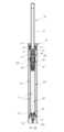
如圖1至圖5所示,本發明第一實施例的行程可調氣油壓裝置主要包含一缸體10以及設於其中的一作動管20、一第一閥組100及一第二閥組200;其中,該第一閥組100包括一油封閥座30及一第一活塞桿50並設於該缸體10的底端,該第二閥組200包括一活塞閥座40及一第二活塞桿60並設於該缸體10的頂端。As shown in FIGS. 1 to 5 , the stroke-adjustable gas-oil pressure device of the first embodiment of the present invention mainly comprises a
其中,如圖1,該缸體10包含一外管11、一內管12及一油封13;該油封13密封固設於該外管11及該內管12的頂端,該油封13的軸心貫設一軸孔131,該油封13的底部蓋設於該內管12的頂端上,該內管12的頂緣密封抵設於該軸孔131的周側平面上。As shown in FIG1 , the
於本發明第一實施例中,如圖4、圖5所示,該油封13成形為多階圓柱體,該油封13的頂部形成圓餅狀與該外管11的頂端管口嵌合固定,該油封13的中段自該頂部收縮形成並於周面嵌設有二墊圈與該外管11的內面密封結合,該油封13的底部周緣沿軸向凸起形成一環凹壁132,該環凹壁132內面凹入嵌設有一墊圈;令該內管12的頂端插置於該環凹壁132界定形成的槽口中,且該內管12的頂緣抵設於該軸孔131的周側平面上,該環凹壁132的內面與該內管12的外面之間透過該墊圈密封結合,使該內管12的內腔與外部於頂端處密封隔開而不連通。In the first embodiment of the present invention, as shown in FIG. 4 and FIG. 5, the
於本發明第一實施例中,如圖4、圖5所示,設於該油封13中段周面的二墊圈為圓形剖面墊圈;設於該環凹壁132內凹處的墊圈為圓形剖面墊圈。In the first embodiment of the present invention, as shown in FIG. 4 and FIG. 5 , the two washers disposed on the middle circumference of the
於本發明第一實施例中,「密封結合」係指透過設置密封墊圈以使封閉構件表面之間的空隙,並使兩構件之間迫緊結合,且當施予其中一構件的外力大於迫緊結合之摩擦力時,被施予外力之該構件可相對另一構件活動位移。例如,如圖4、圖5所示,所述作動管20的外表面與該油封13軸孔131的孔壁之間設有二墊圈;當該作動管20未受外力時,該作動管20透過其外表面與該二墊圈之間的摩擦力而被定位;當該作動管20受到的軸向外力大於該作動管20表面與該墊圈之間摩擦力時,該作動管20被該軸向外力制動而下降收縮至該缸體10內,或者上升外伸至該缸體10外。In the first embodiment of the present invention, "sealed bonding" refers to the provision of a sealing gasket to close the gap between the surfaces of the components and to make the two components tightly bonded, and when the external force applied to one of the components is greater than the friction force of the tight bonding, the component to which the external force is applied can move relative to the other component. For example, as shown in FIGS. 4 and 5 , two washers are provided between the outer surface of the
其中,如圖1、圖4、圖5所示,該作動管20內部設有軸孔貫穿兩端,該軸孔內設有由下往上收縮孔徑之一收縮孔段21,該作動管20的軸孔於該收縮孔段以下形成一插孔段22,供密封結合地套置於該活塞閥座40的連軸部42外部,該作動管20的軸孔於該收縮孔段以上形成一組接孔段23,供設置一制動開關(圖未示)以牽引該第二活塞桿60下壓開啟或復位關閉該活塞閥座40的第二閥口47。As shown in FIGS. 1 , 4 and 5 , the actuating
其中,如圖2、圖3所示,該油封閥座30成形為多階圓柱體,其軸心處成形為一軸管部31,該軸管部31的頂端外部擴張形成一大徑部32及一小徑部33,該大徑部32的周面透過墊圈與該外管11的內面密封結合,該小徑部33位於該軸管部31的末端,該小徑部33的周面透過墊圈與該內管12的內面密封結合;該軸管部31與該內管12連通處形成一第一閥口34;藉此,該外管11的內面、該內管12的外面與該油封13、該油封閥座30之間共同形成一油氣混合室R1,該軸管部31的周壁開設有複數個孔道35與該油氣混合室R1連通。As shown in FIG. 2 and FIG. 3 , the oil
於本發明第一實施例中,如圖2、圖3所示,該外管11的底端內面設有一環凹槽111,一C形扣36嵌設於該環凹槽111,該油封閥座30透過該C形扣36限位而封設於該外管11及該內管12的底端。In the first embodiment of the present invention, as shown in FIG. 2 and FIG. 3 , the inner surface of the bottom end of the
於本發明第一實施例中,如圖2、圖3所示,該油封閥座30的孔道35係自該軸管部31沿徑向開設形成於該大徑部32及該小徑部33之間。根據本發明實施例,該油封閥座30的孔道35數量可為兩個以上,較佳為偶數個,更佳為六個,但不限於此。In the first embodiment of the present invention, as shown in FIG. 2 and FIG. 3 , the
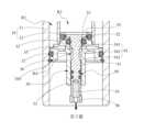
其中,如圖4、圖5所示,該活塞閥座40成形為中空軸桿,其中段成形為一活塞部41,該活塞閥座40的頂底兩端分別收縮形成一連軸部42及一閥座部43;該連軸部42與該作動管20的底端固接;該活塞部41的外面透過嵌設若干墊圈與該內管12的內面密封結合,該內管12的內面、該作動管20的外面與該油封13、該活塞閥座40的活塞部41之間共同形成一上油室R2,該內管12的內面與該活塞閥座40的活塞部41、該油封閥座30之間共同形成一下油室R3。As shown in FIGS. 4 and 5 , the
該活塞閥座40於該活塞部41和該連軸部42的內部貫設有一軸道44,該軸道44貫穿該連軸部42與該作動管20的內部連通,該活塞閥座40於該軸道44的周壁開設有複數通道46連通至該上油室R2;該閥座部43的內部自該軸道44擴張形成一槽道45,該槽道45自該軸道44延伸成形有一外擴段451及一組接段452,該閥座部43於該外擴段451開設有複數第二閥口47連通至該下油室R3。The
於本發明第一實施例中,如圖4、圖5所示,該閥座部43的外部另設有一外套件48封閉該槽道45的開口。該外套件48成形為中空圓柱形套件,具有相對的封閉端及開放端,該外套件48的內部於封閉端形成一槽部481,該外套件48自該槽部481朝向開放端擴張形成一套接部482,該套接部482的末端內面設有一環凸肋483,該活塞閥座40的閥座部43外面設有一環槽431,該環槽431內嵌設有一墊圈;令該外套件48卡扣套置於該活塞閥座40的閥座部43底端外部,該套接部482套置固定於該閥座部43的外面,該外套件48透過該環凸肋483與該閥座部43的環槽431凹凸卡扣而固定結合,該外套件48的末端周緣經該墊圈與該閥座部43的外面密封結合;該閥座部43的末端位於該槽部481與該套接部482鄰接處,且該槽部481的槽口與該閥座部43的槽道45末端開口對應連通;該彈簧49一端安裝於該外套件48的槽部481中,另一端抵壓於該第二活塞桿60的活塞頭63底部端面上,以提供該第二活塞桿60上升復位的外力。In the first embodiment of the present invention, as shown in FIG. 4 and FIG. 5 , an
於本發明第一實施例中,如圖4、圖5所示,該活塞閥座40的通道46係自該軸道44沿徑向開設形成於該活塞部41及該連軸部42之間。根據本發明實施例,該活塞閥座40的通道46數量可為兩個以上,較佳為偶數個,更佳為六個,但不限於此。In the first embodiment of the present invention, as shown in FIG. 4 and FIG. 5 , the
於本發明第一實施例中,如圖4、圖5所示,該活塞閥座40的第二閥口47係自該槽道45沿徑向開設形成於該槽道45的外擴段451。根據本發明實施例,該活塞閥座40的第二閥口47數量可為兩個以上,較佳為偶數個,更佳為六個,但不限於此。In the first embodiment of the present invention, as shown in FIG. 4 and FIG. 5 , the
於本發明第一實施例中,如圖4、圖5所示,該作動管20的軸孔自該插孔段22底端擴張形成一擴槽24;該活塞閥座40的連軸部42與該活塞部41鄰接處凸出形成一環肩部421;令該活塞閥座40的連軸部42插置於該作動管20的插孔段22中,該連軸部42的末端抵制限位於該作動管20的收縮孔段21下緣上,且該環肩部421與該擴槽24之間設有一墊圈密封結合。In the first embodiment of the present invention, as shown in FIG. 4 and FIG. 5 , the axial hole of the
於本發明第一實施例中,如圖4、圖5所示,該活塞閥座40的活塞部41的外面環設有一上凹槽及一下凹槽,該上凹槽中設有三個剖面呈方形的墊圈,該下凹槽中設有一個剖面概呈膠囊形狀的圓筒狀墊圈。該活塞部41與該內管12內面之間透過前述四個墊圈密封結合。In the first embodiment of the present invention, as shown in Fig. 4 and Fig. 5, the outer ring of the
其中,如圖2、圖3所示,該第一活塞桿50的兩端部分別成形為一軸部51及一活塞頭52,該軸部51及該活塞頭52之間收束形成一收縮部54,該收縮部54具有透過直徑變化而分別與該軸部51及該活塞頭52一體連接的一下過渡段542及一上過渡段541,該上過渡段541與該下過渡段542之間成形為直徑固定的一頸段543。該第一活塞桿50活動穿置於該油封閥座30的軸管部31中,該軸管部31的內面與該第一活塞桿50的收縮部54之間共同形成一下油腔R4;該油封閥座30的該第一閥口34、該下油腔R4與該孔道35共同形成第一油道。藉此,該油封閥座30的該軸管部31末端開口經擴張形成該第一閥口34,該第一活塞桿50的該活塞頭52末端擴張形成一圓餅狀的擋止部53;該第一油道透過該活塞頭52及該擋止部53活動地嵌合或退離該油封閥座30的該軸管部31末端開口及該第一閥口34而封閉或開啟。As shown in FIGS. 2 and 3 , the two ends of the
於本發明第一實施例中,該油封閥座30的該軸管部31在該第一閥口34至該孔道35的內面嵌設一墊圈。如圖2,該第一活塞桿50嵌合封閉該第一油道時,該擋止部53封嵌於該第一閥口34上,該活塞頭52嵌入該油封閥座30的軸管部31內,且該活塞頭52的外面與該軸管部31的內面之間透過該墊圈密封結合而阻斷該第一油道。如圖3,該第一活塞桿50退離開啟該第一油道時,該擋止部53及部分的該活塞頭52伸入至該下油室R3中,該活塞頭52的外面完全退離該軸管部31內面的墊圈,令該收縮部54與該軸管部31之間的下油腔R4上下導通,使該第一油道連通該油氣混合室R1及該下油室R3。In the first embodiment of the present invention, the
具體地,如圖3,該下油腔R4上下導通時,該第一活塞桿50的收縮部54的該上過渡段541、該頸段543及該下過渡段542分別對應於該油封閥座30的第一閥口34與該軸管部31開口轉接處、該軸管部31內面的墊圈及該孔道35開口。Specifically, as shown in FIG3 , when the lower oil chamber R4 is connected up and down, the
於本發明第一實施例中,如圖2、圖3所示,該軸部51的外面嵌設二墊圈以和該軸管部31的底端內面密封結合;該二墊圈為圓形剖面墊圈。In the first embodiment of the present invention, as shown in FIG. 2 and FIG. 3 , two washers are embedded on the outer surface of the
於本發明第一實施例中,如圖2、圖3所示,該第一活塞桿50的底端還軸向凹設一安裝槽55供固設一連動件56,該連動件56用以和一制動開關(圖未示)組接,以牽引該第一活塞桿50關閉或開啟該油封閥座30的第一閥口34。In the first embodiment of the present invention, as shown in FIGS. 2 and 3 , a mounting
其中,如圖4、圖5所示,該第二活塞桿60的兩端分別成形為一組接軸頭62及一活塞頭63,該組接軸頭62及該活塞頭63之間收束形成一桿身61。該第二活塞桿60活動穿置於該活塞閥座40的該軸道44與該槽道45中,該組接軸頭62的外面嵌設墊圈與該軸道44的內面密封結合,該活塞頭63的外面兩端嵌設有二墊圈631與該槽道45的組接段452內面密封結合;該第二活塞桿60的桿身61與活塞閥座40的軸道44及槽道45的內面之間共同形成一上油腔R5;該活塞閥座40的該第二閥口47、該上油腔R5與該通道46共同形成第二油道。As shown in FIG. 4 and FIG. 5 , two ends of the
如圖4,該第二活塞桿60受該彈簧49抵壓,令該活塞頭63常態上頂於該軸道44與該槽道45鄰接處,使該活塞頭63位於該槽道45的外擴段451且該二墊圈631阻斷該第二閥口47與該上油腔R5連通。如圖5,當該第二活塞桿60受外力向下位移壓縮該彈簧49時,使該活塞頭63位移至該槽道45的組接段452內,且該二墊圈631下移錯開該第二閥口47,使該第二閥口47與該上油腔R5連通。As shown in FIG4 , the
此外,於本發明第一實施例中,如圖4、圖5,該第二活塞桿60的活塞頭63自其底部端面另軸向開設一油孔道64,該油孔道64的底端與該外套件48的槽部481連通,該油孔道64的頂端沿徑向開設有複數油孔65與該上油腔R5連通;該槽部481、該油孔道64與該油孔65共同形成平衡油道,以使該第二活塞桿60在具有復位能力進行軸向位移時,保持該槽部481與該上油腔R5之間的壓力平衡。In addition, in the first embodiment of the present invention, as shown in Figures 4 and 5, the
於本發明第一實施例中,如圖4、圖5所示,該第二活塞桿60的組接軸頭62外面嵌設一個圓形剖面墊圈,該活塞頭63外面的二墊圈631分別為圓形剖面墊圈。In the first embodiment of the present invention, as shown in FIG. 4 and FIG. 5 , a circular cross-section gasket is embedded outside the
於本發明第一實施例中,該油氣混合室R1的下部填充油體A,上部根據使用需求填充具特定壓力範圍的氣體B;該上油室R2、該下油室R3以及該第一油道(包含該第一閥口34、該下油腔R4、該孔道35)、該第二油道(包含該第二閥口47、該上油腔R5、該通道46)、該平衡油道(包含該外套件48的槽部481空間、該第二活塞桿60的油孔道64和油孔65)內部充滿油體A。藉此,本發明實施例透過在缸體10內部的密封空間及流道中填充油體A及氣體B形成內壓,配合第一活塞桿50及/或第二活塞桿60關閉阻斷或開啟導通油道,以改變該缸體10的內壓,達到控制該作動管20相對缸體10進行下壓收縮或上提復位。In the first embodiment of the present invention, the lower part of the oil-gas mixing chamber R1 is filled with oil body A, and the upper part is filled with gas B with a specific pressure range according to the use requirements; the upper oil chamber R2, the lower oil chamber R3 and the first oil channel (including the
如圖6、圖7,本發明行程可調氣油壓裝置的無段升降調整,是在該第二活塞桿60關閉該第二閥口47(即第二油道被阻斷)的狀態下,透過控制該第一活塞桿50使該作動管20能夠相對該缸體10升降後定位完成。其中,如圖6至圖7,該第一活塞桿50被開啟而導通該第一油道後,施予外力使該作動管20下壓內縮至缸體10中,該活塞閥座40隨之在該外管11內往下位移而擠壓該下油室R3的油體A,使油體A經該第一油道自該下油室R3流入該油氣混合室R1中;此時,該油氣混合室R1中的氣體B被壓縮而形成與該外力平衡的內壓;當該外力被持續施予該作動管20時,該作動管20保持下壓內縮於缸體10中;當該外力被移除時,透過氣體B被壓縮形成的內壓使油氣混合室R1中的油體A回流至下油室R3中,從而使該活塞閥座40被頂升位移並帶動該作動管20上提復位。As shown in Fig. 6 and Fig. 7, the stepless lifting and lowering adjustment of the stroke-adjustable gas-oil pressure device of the present invention is completed by controlling the
此外,於本發明第一實施例中,在開啟該第一閥口34並關閉該第二閥口47進行無段升降操作時,該上油室R2形成密封空間,因此,該上油室R2內部隨該活塞閥座40往下位移而擴大容積形成負壓,該負壓在該外力被移除時,隨該活塞閥座40復位而解除。In addition, in the first embodiment of the present invention, when the
如圖8、圖9、圖10,本發明行程可調氣油壓裝置的作動管20外露總行程調整,係如圖8在該第一活塞桿50開啟該第一閥口34且該第二活塞桿60開啟該第二閥口47(即第一油道和第二油道同時被導通)的狀態下,使該作動管20能夠相對該缸體10升降至所需位置,此時,藉由該第二油道導通使油體A流入擴大的上油室R2中達到壓力平衡(不形成負壓);接著,如圖9透過控制該第二活塞桿60關閉該第二閥口47(即第二油道被阻斷),使該作動管20在無施加外力時被定位於所需位置,從而達到調整該作動管20外露總行程之目的。進而,如圖9至圖10,該作動管20能夠透過控制該第一活塞桿50,而在被施加外力時相對該缸體10在調整後總行程長度內進行無段升降調整後定位。此外,當外力移除時,由於該第二油道關閉,使該上油室R2內的油體A無法被壓縮擠出,因此,該作動管20的外露長度將上提復位至調整後總行程的最大長度,使本發明實施例形成具有升降高度記憶功能的行程可調氣油壓裝置。As shown in Figs. 8, 9 and 10, the total exposed stroke of the
本發明透過該第二閥口47的開啟與否使得該上油室R2依據該第二閥口47的開啟/關閉以選擇性的形成密封空間或與該第二油道導通<以使得本發明行程可調氣油壓裝置應用於自行車時。可以配合使用者之高度習慣呈現多種調整模式(無段升降調整以及外露總行程調整)以達成具備記憶功能之自行車座墊。The present invention selectively forms a sealed space or communicates with the second oil passage according to the opening/closing of the
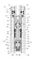
如圖11至圖13所示,本發明第二實施例的行程可調氣油壓裝置與第一實施例的結構大致相同,第二實施例與第一實施例的區別主要在於該第二閥組200的結構。具體地,本發明第二實施例的行程可調氣油壓裝置同樣包括該缸體10、該作動管20,由該油封閥座30及該第一活塞桿50構成的第一閥組100,該第二閥組200則包括一活塞閥座70及一第二活塞桿80。As shown in FIGS. 11 to 13 , the stroke-adjustable gas-oil pressure device of the second embodiment of the present invention is substantially the same in structure as the first embodiment, and the difference between the second embodiment and the first embodiment mainly lies in the structure of the
於本發明第二實施例中,該活塞閥座70成形為多階圓柱體,其軸心處成形為一軸管部71,該軸管部71的頂端外部擴張形成一小徑部72及一大徑部73,該小徑部72的周面透過墊圈與該作動管20插孔段22的內面密封結合,該大徑部73位於該軸管部71的末端,該大徑部73的周面透過墊圈與該內管12的內面密封結合;該軸管部71與該內管12連通處形成一第二閥口74;該內管12的內面、該作動管20的外面與該油封13、該活塞閥座70的頂端之間共同形成該上油室R2,該內管12的內面與該活塞閥座70的底端、該油封閥座30之間共同形成該下油室R3。藉此,該活塞閥座70的軸管部71的周壁開設有複數個孔道75連通至該上油室R2;該第二活塞桿80活動穿置於該活塞閥座70的該軸管部71中以關閉或開啟該第二閥口74,使該第二油道阻斷或導通。In the second embodiment of the present invention, the
於本發明第二實施例中,如圖12、圖13所示,該活塞閥座70的孔道75係自該軸管部71沿徑向開設形成於該小徑部72及該大徑部73之間。根據本發明實施例,該活塞閥座70的孔道75數量可為兩個以上,較佳為偶數個,更佳為六個,但不限於此。In the second embodiment of the present invention, as shown in FIG. 12 and FIG. 13 , the
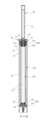
於本發明第二實施例中,該第二活塞桿80的兩端部分別成形為一軸部81及一活塞頭82,該軸部81及該活塞頭82之間收束形成一收縮部84,該收縮部84具有透過直徑變化而分別與該軸部81及該活塞頭82一體連接的一下過渡段及一上過渡段,該上過渡段與該下過渡段之間成形為直徑固定的一頸段。該第二活塞桿80活動穿置於該活塞閥座70的軸管部71中,該軸管部71的內面與該第二活塞桿80的收縮部84之間共同形成該上油腔R5;該活塞閥座70的該第二閥口74、該上油腔R5與該孔道75共同形成本發明第二實施例的第二油道。藉此,該活塞閥座70的該軸管部71末端開口經擴張形成該第二閥口74,該第二活塞桿80的該活塞頭82末端擴張形成一圓餅狀的擋止部83;該第二油道透過該活塞頭82及該擋止部83活動地嵌合或退離該活塞閥座70的該軸管部71末端開口及該第二閥口74而封閉或開啟。In the second embodiment of the present invention, the two end portions of the
於本發明第二實施例中,該活塞閥座70的該軸管部71在該第二閥口74至該孔道75的內面嵌設一墊圈。如圖12,該第二活塞桿80嵌合封閉該第二油道時,該擋止部83封嵌於該第二閥口74上,該活塞頭82嵌入該活塞閥座70的軸管部71內,且該活塞頭82的外面與該軸管部71的內面之間透過該墊圈密封結合而阻斷該第二油道。如圖13,該第二活塞桿80退離開啟該第二油道時,該擋止部83及部分的該活塞頭82伸入至該下油室R3中,該活塞頭82的外面完全退離該軸管部71內面的墊圈,令該收縮部84與該軸管部71之間的上油腔R5上下導通,使該第二油道連通該上油室R2及該下油室R3。In the second embodiment of the present invention, the
本發明第二實施例的行程可調氣油壓裝置的操作與第一實施例相同;當需要進行無段升降調整時,透過控制該第一活塞桿50開啟該第一油道以及控制該第二活塞桿80關閉該第二油道,以使填充於該下油室R3的油體A隨壓縮或拉伸該作動管20而經由第一油道流入或流出油氣混合室R1,實現作動管20的升降調整。在作動管20調整至所需高度後,透過控制該第一活塞桿50關閉該第一油道,阻斷油體A流動,即可使作動管20定位於調整後的高度位置,實現作動管20進行無段升降調整後定位之目的。The operation of the stroke-adjustable gas-oil pressure device of the second embodiment of the present invention is the same as that of the first embodiment; when stepless lifting adjustment is required, the
當需要進行作動管20外露總行程調整時,可先透過控制該第一活塞桿50開啟該第一油道以及控制該第二活塞桿80開啟該第二油道,以使填充於該下油室R3的油體A隨作動管20的壓縮或拉伸,而同時經由該第一油道流入或流出該油氣混合室R1以及經由該第二油道流入或流出該上油室R2,並在作動管20調整至所需外露總行程時,透過控制該第二活塞桿80關閉該第二油道,阻斷油體A於第二油道流動,即可固定作動管20的外露總行程。When the total exposed stroke of the
以上所述,僅是本發明的較佳實施例,並非對本發明任何形式上的限制,任何所屬技術領域中具有通常知識者,若在不脫離本發明所提技術方案的範圍內,利用本發明所揭示技術內容所作出局部更動或修飾的等效實施例,並且未脫離本發明的技術方案內容,均仍屬本發明的技術方案的範圍內。The above is only the preferred embodiment of the present invention and does not limit the present invention in any form. Any person with ordinary knowledge in the relevant technical field, if within the scope of the technical solution proposed by the present invention, makes partial changes or modifications to the technical content disclosed by the present invention, and does not deviate from the technical solution content of the present invention, all equivalent embodiments still fall within the scope of the technical solution of the present invention.
20:作動管 21:收縮孔段 22:插孔段 23:組接孔段 24:擴槽 10:缸體 11:外管 111:環凹槽 12:內管 13:油封 131:軸孔 20:作動管 21:收縮孔段 22:插孔段 23:組接孔段 24:擴槽 30:油封閥座 31:軸管部 32:大徑部 33:小徑部 34:第一閥口 35:孔道 36:C形扣 40:活塞閥座 41:活塞部 42:連軸部 421:環肩部 43:閥座部 431:環槽 44:軸道 45:槽道 451:外擴段 452:組接段 46:通道 47:第二閥口 48:外套件 481:槽部 482:套接部 483:環凸肋 49:彈簧 50:第一活塞桿 51:軸部 52:活塞頭 53:擋止部 54:收縮部 541:上過渡段 542:下過渡段 543:頸段 55:安裝槽 56:連動件 60:第二活塞桿 61:桿身 62:組接軸頭 63:活塞頭 631:墊圈 64:油孔道 65:油孔 70:活塞閥座 71:軸管部 72:小徑部 73:大徑部 74:第二閥口 75:孔道 80:第二活塞桿 81:軸部 82:活塞頭 83:擋止部 84:收縮部 A:油體 B:氣體 R1:油氣混合室 R2:上油室 R3:下油室 R4:下油腔 R5:上油腔20: Actuating tube21: Reduction hole section22: Insertion hole section23: Assembly hole section24: Expansion groove10: Cylinder body11: Outer tube111: Ring groove12: Inner tube13: Oil seal131: Shaft hole20: Actuating tube21: Reduction hole section22: Insertion hole section23: Assembly hole section24: Expansion groove30: Oil seal valve seat31: Shaft tube section32: Large diameter section33: Small diameter section34: First valve port35: Hole36: C-shaped buckle40: Piston valve seat41: Piston section42: Connecting shaft section421: Ring shoulder section43: Valve seat431: Ring groove44: Shaft45: Groove451: External expansion section452: Assembly section46: Channel47: Second valve port48: External assembly481: Groove482: Sleeve section483: Ring rib49: Spring50: First piston rod51: Shaft52: Piston head53: Stopper54: Contraction section541: Upper transition section542: Lower transition section543: Neck section55: Mounting groove56: Linkage60: Second piston rod61: Rod body62: Assembly shaft63: Piston head631: Gasket64: Oil channel65: Oil hole70: Piston valve seat71: Shaft tube72: Small diameter73: Large diameter74: Second valve port75: Channel80: Second piston rod81: Shaft82: Piston head83: Stopper84: ContractionA: Oil bodyB: GasR1: Oil-gas mixing chamberR2: Upper oil chamberR3: Lower oil chamberR4: Lower oil chamberR5: Upper oil chamber
圖1是本發明第一實施例的整體結構剖視示意圖。 圖2是本發明第一實施例的第一閥組呈關閉狀態的剖視示意圖。 圖3是本發明第一實施例的第一閥組呈開啟狀態的剖視示意圖。 圖4是本發明第一實施例的第二閥組呈關閉狀態的剖視示意圖。 圖5是本發明第一實施例的第二閥組呈開啟狀態的剖視示意圖。 圖6至圖7是本發明第一實施例的第一閥組呈關閉狀態下,調整作動管無段升降的動作示意圖。 圖8至圖10是本發明第一實施例先調整固定作動管的最終總行程(圖8至圖9),後於該最終總行程內進行無段升降(圖9、圖10)的動作示意圖。 圖11是本發明第二實施例的整體結構剖視示意圖。 圖12是本發明第二實施例的第二閥組呈開啟狀態的剖視示意圖。 圖13是本發明第二實施例的第二閥組呈關閉狀態的剖視示意圖。Figure 1 is a schematic cross-sectional view of the overall structure of the first embodiment of the present invention.Figure 2 is a schematic cross-sectional view of the first valve group of the first embodiment of the present invention in a closed state.Figure 3 is a schematic cross-sectional view of the first valve group of the first embodiment of the present invention in an open state.Figure 4 is a schematic cross-sectional view of the second valve group of the first embodiment of the present invention in a closed state.Figure 5 is a schematic cross-sectional view of the second valve group of the first embodiment of the present invention in an open state.Figures 6 to 7 are schematic views of the action of adjusting the stepless lifting of the actuating pipe when the first valve group of the first embodiment of the present invention is in a closed state.Figures 8 to 10 are schematic diagrams of the first embodiment of the present invention, in which the final total stroke of the fixed actuating tube is first adjusted (Figures 8 to 9), and then stepless lifting (Figures 9 and 10) is performed within the final total stroke.Figure 11 is a schematic cross-sectional diagram of the overall structure of the second embodiment of the present invention.Figure 12 is a schematic cross-sectional diagram of the second valve group of the second embodiment of the present invention in an open state.Figure 13 is a schematic cross-sectional diagram of the second valve group of the second embodiment of the present invention in a closed state.
10:缸體10: Cylinder body
11:外管11: External pipe
12:內管12: Inner tube
13:油封13: Oil seal
131:軸孔131: Axle hole
20:作動管20: Actuator tube
21:收縮孔段21: Contraction hole section
22:插孔段22: Jack section
23:組接孔段23: Assembly hole section
30:油封閥座30: Oil seal valve seat
34:第一閥口34: First valve
35:孔道35: Kongdao
40:活塞閥座40: Piston valve seat
46:通道46: Channel
47:第二閥口47: Second valve
50:第一活塞桿50: First piston rod
60:第二活塞桿60: Second piston rod
R1:油氣混合室R1: Oil-gas mixing chamber
R2:上油室R2: Oiling room
R3:下油室R3: Lower oil chamber
R4:下油腔R4: Lower oil chamber
R5:上油腔R5: Oiling cavity
A:油體A: Oil body
B:氣體B: Gas
Claims (10)
Translated fromChinesePriority Applications (4)
| Application Number | Priority Date | Filing Date | Title |
|---|---|---|---|
| TW112124641ATW202502592A (en) | 2023-06-30 | 2023-06-30 | Adjustable air oil pressure device |
| CN202321967203.9UCN220298641U (en) | 2023-06-30 | 2023-07-25 | Stroke adjustable pneumatic and hydraulic device |
| DE202023104757.2UDE202023104757U1 (en) | 2023-06-30 | 2023-08-21 | Stroke-adjustable pneumatic-hydraulic device |
| US18/453,752US12384480B2 (en) | 2023-06-30 | 2023-08-22 | Adjustable pneumatic-hydraulic pressure unit for stroke control |
Applications Claiming Priority (1)
| Application Number | Priority Date | Filing Date | Title |
|---|---|---|---|
| TW112124641ATW202502592A (en) | 2023-06-30 | 2023-06-30 | Adjustable air oil pressure device |
Publications (1)
| Publication Number | Publication Date |
|---|---|
| TW202502592Atrue TW202502592A (en) | 2025-01-16 |
Family
ID=88414569
Family Applications (1)
| Application Number | Title | Priority Date | Filing Date |
|---|---|---|---|
| TW112124641ATW202502592A (en) | 2023-06-30 | 2023-06-30 | Adjustable air oil pressure device |
Country Status (4)
| Country | Link |
|---|---|
| US (1) | US12384480B2 (en) |
| CN (1) | CN220298641U (en) |
| DE (1) | DE202023104757U1 (en) |
| TW (1) | TW202502592A (en) |
Family Cites Families (20)
| Publication number | Priority date | Publication date | Assignee | Title |
|---|---|---|---|---|
| US9422018B2 (en)* | 2008-11-25 | 2016-08-23 | Fox Factory, Inc. | Seat post |
| US8833786B2 (en)* | 2011-08-24 | 2014-09-16 | Trek Bicycle Corporation | Automatic drop seatpost |
| US9073592B2 (en)* | 2011-10-12 | 2015-07-07 | Jung Yu Hsu | Height adjustable seat tube with oil storage unit |
| TWM532004U (en)* | 2016-01-13 | 2016-11-11 | J D Components Co Ltd | Bicycle hydraulic/pneumatic lifting seat-tube assembly |
| US20170227082A1 (en)* | 2016-02-04 | 2017-08-10 | Kind Shock Hi-Tech Co., Ltd. | Flow adjustment and oil path separation structure of shock absorber |
| TWI570012B (en)* | 2016-02-24 | 2017-02-11 | 台灣穗高工業股份有限公司 | Bicycle seat height adjustment mechanism |
| US10549803B2 (en)* | 2017-06-30 | 2020-02-04 | Sram, Llc | Seat post assembly |
| US11180212B2 (en)* | 2018-07-17 | 2021-11-23 | Shimano Inc. | Fluid flow control structure for a telescopic apparatus of a human powered vehicle |
| CH716006A2 (en)* | 2019-03-28 | 2020-09-30 | Bmc Switzerland Ag | Adjustable seat post assembly. |
| US11548580B2 (en)* | 2020-01-08 | 2023-01-10 | Shimano Inc. | Telescopic apparatus for human-powered vehicle |
| TW202216518A (en)* | 2020-05-04 | 2022-05-01 | 加拿大商綠房控股有限公司 | Device for adjusting a seat position of a bicycle seat |
| US11661129B2 (en)* | 2020-06-30 | 2023-05-30 | Sram, Llc | Pneumatic only height adjust seat post assembly |
| US12103624B2 (en)* | 2020-08-04 | 2024-10-01 | Shimano Inc. | Rider-posture changing device and control system of human-powered vehicle |
| US12030575B2 (en)* | 2020-10-27 | 2024-07-09 | Shimano Inc. | Rider-posture changing device and control system of human-powered vehicle |
| TWM609894U (en)* | 2020-11-13 | 2021-04-01 | 董菁 | Bicycle seat tube lifting structure |
| US20220210650A1 (en)* | 2020-12-28 | 2022-06-30 | Fox Factory, Inc. | Wireless switch for an active component |
| TWM616687U (en)* | 2021-01-25 | 2021-09-11 | 久鼎金屬實業股份有限公司 | Gas hydraulic control valve |
| EP4108557B1 (en)* | 2021-06-24 | 2025-05-14 | Fox Factory, Inc. | Electronically actuated dropper seatpost |
| US12179870B2 (en)* | 2022-02-18 | 2024-12-31 | Sram, Llc | Seat post assembly with an adjustable stroke |
| TWM640748U (en)* | 2022-04-27 | 2023-05-11 | 凱薩克科技股份有限公司 | Seat height adjustment device |
- 2023
- 2023-06-30TWTW112124641Apatent/TW202502592A/enunknown
- 2023-07-25CNCN202321967203.9Upatent/CN220298641U/enactiveActive
- 2023-08-21DEDE202023104757.2Upatent/DE202023104757U1/enactiveActive
- 2023-08-22USUS18/453,752patent/US12384480B2/enactiveActive
Also Published As
| Publication number | Publication date |
|---|---|
| DE202023104757U1 (en) | 2023-10-04 |
| US20250002101A1 (en) | 2025-01-02 |
| CN220298641U (en) | 2024-01-05 |
| US12384480B2 (en) | 2025-08-12 |
Similar Documents
| Publication | Publication Date | Title |
|---|---|---|
| TWI589475B (en) | Adjustable seat tube structure and bicycle thereof | |
| US4960188A (en) | Single-tube vibration damper of variable damping force | |
| US7540362B2 (en) | Adjustable-length gas spring | |
| JP2003166585A (en) | Damping force adjustable hydraulic shock absorber | |
| CN105805218B (en) | A magneto-rheological valve-controlled damping controllable shock absorber | |
| TWM562805U (en) | Bicycle seat tube lifting device | |
| TWM532004U (en) | Bicycle hydraulic/pneumatic lifting seat-tube assembly | |
| TWM649991U (en) | Lifting device with adjustable stroke | |
| TW202502592A (en) | Adjustable air oil pressure device | |
| CN210634677U (en) | Adjustable Overall Length Pneumatic Dropper Seatpost | |
| CN208021596U (en) | Seat tube lifting device of bicycle | |
| JPS6216545Y2 (en) | ||
| TW202506476A (en) | Adjustable air oil pressure device | |
| TWM649594U (en) | Stroke adjustable pneumatic and hydraulic device | |
| US4832318A (en) | Lifting telescoping tube | |
| TWI638740B (en) | Bicycle seat tube lifting device | |
| CN216949950U (en) | Arbitrary position stopper | |
| CN212359448U (en) | Hydraulic stepless positioner | |
| TWM648998U (en) | Stroke adjustable pneumatic and hydraulic device | |
| CN215043290U (en) | Pneumatic-hydraulic type automatic lifting device | |
| TWI872610B (en) | Lifting device with adjustable stroke | |
| TWM589738U (en) | Gas-hydraulic lifting seatpost with adjustable total length | |
| CN209925496U (en) | Pressure bar | |
| JPH0245540Y2 (en) | ||
| US20240240686A1 (en) | Lockable gas spring |