TW202448540A - Patient interface - Google Patents
Patient interfaceDownload PDFInfo
- Publication number
- TW202448540A TW202448540ATW113106585ATW113106585ATW202448540ATW 202448540 ATW202448540 ATW 202448540ATW 113106585 ATW113106585 ATW 113106585ATW 113106585 ATW113106585 ATW 113106585ATW 202448540 ATW202448540 ATW 202448540A
- Authority
- TW
- Taiwan
- Prior art keywords
- nasal
- gas
- prong
- interface
- flow
- Prior art date
Links
Images


Classifications
- A—HUMAN NECESSITIES
- A61—MEDICAL OR VETERINARY SCIENCE; HYGIENE
- A61M—DEVICES FOR INTRODUCING MEDIA INTO, OR ONTO, THE BODY; DEVICES FOR TRANSDUCING BODY MEDIA OR FOR TAKING MEDIA FROM THE BODY; DEVICES FOR PRODUCING OR ENDING SLEEP OR STUPOR
- A61M16/00—Devices for influencing the respiratory system of patients by gas treatment, e.g. ventilators; Tracheal tubes
- A61M16/06—Respiratory or anaesthetic masks
- A61M16/0666—Nasal cannulas or tubing
- A—HUMAN NECESSITIES
- A61—MEDICAL OR VETERINARY SCIENCE; HYGIENE
- A61M—DEVICES FOR INTRODUCING MEDIA INTO, OR ONTO, THE BODY; DEVICES FOR TRANSDUCING BODY MEDIA OR FOR TAKING MEDIA FROM THE BODY; DEVICES FOR PRODUCING OR ENDING SLEEP OR STUPOR
- A61M16/00—Devices for influencing the respiratory system of patients by gas treatment, e.g. ventilators; Tracheal tubes
- A61M16/0003—Accessories therefor, e.g. sensors, vibrators, negative pressure
- A—HUMAN NECESSITIES
- A61—MEDICAL OR VETERINARY SCIENCE; HYGIENE
- A61B—DIAGNOSIS; SURGERY; IDENTIFICATION
- A61B5/00—Measuring for diagnostic purposes; Identification of persons
- A61B5/145—Measuring characteristics of blood in vivo, e.g. gas concentration or pH-value ; Measuring characteristics of body fluids or tissues, e.g. interstitial fluid or cerebral tissue
- A61B5/14542—Measuring characteristics of blood in vivo, e.g. gas concentration or pH-value ; Measuring characteristics of body fluids or tissues, e.g. interstitial fluid or cerebral tissue for measuring blood gases
- A—HUMAN NECESSITIES
- A61—MEDICAL OR VETERINARY SCIENCE; HYGIENE
- A61M—DEVICES FOR INTRODUCING MEDIA INTO, OR ONTO, THE BODY; DEVICES FOR TRANSDUCING BODY MEDIA OR FOR TAKING MEDIA FROM THE BODY; DEVICES FOR PRODUCING OR ENDING SLEEP OR STUPOR
- A61M16/00—Devices for influencing the respiratory system of patients by gas treatment, e.g. ventilators; Tracheal tubes
- A61M16/06—Respiratory or anaesthetic masks
- A61M16/0605—Means for improving the adaptation of the mask to the patient
- A—HUMAN NECESSITIES
- A61—MEDICAL OR VETERINARY SCIENCE; HYGIENE
- A61M—DEVICES FOR INTRODUCING MEDIA INTO, OR ONTO, THE BODY; DEVICES FOR TRANSDUCING BODY MEDIA OR FOR TAKING MEDIA FROM THE BODY; DEVICES FOR PRODUCING OR ENDING SLEEP OR STUPOR
- A61M16/00—Devices for influencing the respiratory system of patients by gas treatment, e.g. ventilators; Tracheal tubes
- A61M16/06—Respiratory or anaesthetic masks
- A61M16/0666—Nasal cannulas or tubing
- A61M16/0672—Nasal cannula assemblies for oxygen therapy
- A—HUMAN NECESSITIES
- A61—MEDICAL OR VETERINARY SCIENCE; HYGIENE
- A61M—DEVICES FOR INTRODUCING MEDIA INTO, OR ONTO, THE BODY; DEVICES FOR TRANSDUCING BODY MEDIA OR FOR TAKING MEDIA FROM THE BODY; DEVICES FOR PRODUCING OR ENDING SLEEP OR STUPOR
- A61M16/00—Devices for influencing the respiratory system of patients by gas treatment, e.g. ventilators; Tracheal tubes
- A61M16/08—Bellows; Connecting tubes ; Water traps; Patient circuits
- A61M16/0866—Passive resistors therefor
- A—HUMAN NECESSITIES
- A61—MEDICAL OR VETERINARY SCIENCE; HYGIENE
- A61M—DEVICES FOR INTRODUCING MEDIA INTO, OR ONTO, THE BODY; DEVICES FOR TRANSDUCING BODY MEDIA OR FOR TAKING MEDIA FROM THE BODY; DEVICES FOR PRODUCING OR ENDING SLEEP OR STUPOR
- A61M16/00—Devices for influencing the respiratory system of patients by gas treatment, e.g. ventilators; Tracheal tubes
- A61M16/10—Preparation of respiratory gases or vapours
- A61M16/1075—Preparation of respiratory gases or vapours by influencing the temperature
- A—HUMAN NECESSITIES
- A61—MEDICAL OR VETERINARY SCIENCE; HYGIENE
- A61B—DIAGNOSIS; SURGERY; IDENTIFICATION
- A61B5/00—Measuring for diagnostic purposes; Identification of persons
- A61B5/02—Detecting, measuring or recording for evaluating the cardiovascular system, e.g. pulse, heart rate, blood pressure or blood flow
- A61B5/024—Measuring pulse rate or heart rate
- A—HUMAN NECESSITIES
- A61—MEDICAL OR VETERINARY SCIENCE; HYGIENE
- A61B—DIAGNOSIS; SURGERY; IDENTIFICATION
- A61B5/00—Measuring for diagnostic purposes; Identification of persons
- A61B5/02—Detecting, measuring or recording for evaluating the cardiovascular system, e.g. pulse, heart rate, blood pressure or blood flow
- A61B5/026—Measuring blood flow
- A61B5/0295—Measuring blood flow using plethysmography, i.e. measuring the variations in the volume of a body part as modified by the circulation of blood therethrough, e.g. impedance plethysmography
- A—HUMAN NECESSITIES
- A61—MEDICAL OR VETERINARY SCIENCE; HYGIENE
- A61B—DIAGNOSIS; SURGERY; IDENTIFICATION
- A61B5/00—Measuring for diagnostic purposes; Identification of persons
- A61B5/08—Measuring devices for evaluating the respiratory organs
- A61B5/0816—Measuring devices for examining respiratory frequency
- A—HUMAN NECESSITIES
- A61—MEDICAL OR VETERINARY SCIENCE; HYGIENE
- A61B—DIAGNOSIS; SURGERY; IDENTIFICATION
- A61B5/00—Measuring for diagnostic purposes; Identification of persons
- A61B5/08—Measuring devices for evaluating the respiratory organs
- A61B5/097—Devices for facilitating collection of breath or for directing breath into or through measuring devices
- A—HUMAN NECESSITIES
- A61—MEDICAL OR VETERINARY SCIENCE; HYGIENE
- A61M—DEVICES FOR INTRODUCING MEDIA INTO, OR ONTO, THE BODY; DEVICES FOR TRANSDUCING BODY MEDIA OR FOR TAKING MEDIA FROM THE BODY; DEVICES FOR PRODUCING OR ENDING SLEEP OR STUPOR
- A61M16/00—Devices for influencing the respiratory system of patients by gas treatment, e.g. ventilators; Tracheal tubes
- A61M16/06—Respiratory or anaesthetic masks
- A61M16/0683—Holding devices therefor
- A—HUMAN NECESSITIES
- A61—MEDICAL OR VETERINARY SCIENCE; HYGIENE
- A61M—DEVICES FOR INTRODUCING MEDIA INTO, OR ONTO, THE BODY; DEVICES FOR TRANSDUCING BODY MEDIA OR FOR TAKING MEDIA FROM THE BODY; DEVICES FOR PRODUCING OR ENDING SLEEP OR STUPOR
- A61M16/00—Devices for influencing the respiratory system of patients by gas treatment, e.g. ventilators; Tracheal tubes
- A61M16/08—Bellows; Connecting tubes ; Water traps; Patient circuits
- A61M16/0816—Joints or connectors
- A—HUMAN NECESSITIES
- A61—MEDICAL OR VETERINARY SCIENCE; HYGIENE
- A61M—DEVICES FOR INTRODUCING MEDIA INTO, OR ONTO, THE BODY; DEVICES FOR TRANSDUCING BODY MEDIA OR FOR TAKING MEDIA FROM THE BODY; DEVICES FOR PRODUCING OR ENDING SLEEP OR STUPOR
- A61M16/00—Devices for influencing the respiratory system of patients by gas treatment, e.g. ventilators; Tracheal tubes
- A61M16/08—Bellows; Connecting tubes ; Water traps; Patient circuits
- A61M16/0875—Connecting tubes
- A—HUMAN NECESSITIES
- A61—MEDICAL OR VETERINARY SCIENCE; HYGIENE
- A61M—DEVICES FOR INTRODUCING MEDIA INTO, OR ONTO, THE BODY; DEVICES FOR TRANSDUCING BODY MEDIA OR FOR TAKING MEDIA FROM THE BODY; DEVICES FOR PRODUCING OR ENDING SLEEP OR STUPOR
- A61M16/00—Devices for influencing the respiratory system of patients by gas treatment, e.g. ventilators; Tracheal tubes
- A61M16/10—Preparation of respiratory gases or vapours
- A61M16/1005—Preparation of respiratory gases or vapours with O2 features or with parameter measurement
- A—HUMAN NECESSITIES
- A61—MEDICAL OR VETERINARY SCIENCE; HYGIENE
- A61M—DEVICES FOR INTRODUCING MEDIA INTO, OR ONTO, THE BODY; DEVICES FOR TRANSDUCING BODY MEDIA OR FOR TAKING MEDIA FROM THE BODY; DEVICES FOR PRODUCING OR ENDING SLEEP OR STUPOR
- A61M16/00—Devices for influencing the respiratory system of patients by gas treatment, e.g. ventilators; Tracheal tubes
- A61M16/10—Preparation of respiratory gases or vapours
- A61M16/1075—Preparation of respiratory gases or vapours by influencing the temperature
- A61M16/1085—Preparation of respiratory gases or vapours by influencing the temperature after being humidified or mixed with a beneficial agent
- A—HUMAN NECESSITIES
- A61—MEDICAL OR VETERINARY SCIENCE; HYGIENE
- A61M—DEVICES FOR INTRODUCING MEDIA INTO, OR ONTO, THE BODY; DEVICES FOR TRANSDUCING BODY MEDIA OR FOR TAKING MEDIA FROM THE BODY; DEVICES FOR PRODUCING OR ENDING SLEEP OR STUPOR
- A61M16/00—Devices for influencing the respiratory system of patients by gas treatment, e.g. ventilators; Tracheal tubes
- A61M16/10—Preparation of respiratory gases or vapours
- A61M16/1075—Preparation of respiratory gases or vapours by influencing the temperature
- A61M16/1095—Preparation of respiratory gases or vapours by influencing the temperature in the connecting tubes
- A—HUMAN NECESSITIES
- A61—MEDICAL OR VETERINARY SCIENCE; HYGIENE
- A61M—DEVICES FOR INTRODUCING MEDIA INTO, OR ONTO, THE BODY; DEVICES FOR TRANSDUCING BODY MEDIA OR FOR TAKING MEDIA FROM THE BODY; DEVICES FOR PRODUCING OR ENDING SLEEP OR STUPOR
- A61M16/00—Devices for influencing the respiratory system of patients by gas treatment, e.g. ventilators; Tracheal tubes
- A61M16/10—Preparation of respiratory gases or vapours
- A61M16/14—Preparation of respiratory gases or vapours by mixing different fluids, one of them being in a liquid phase
- A61M16/16—Devices to humidify the respiration air
- A—HUMAN NECESSITIES
- A61—MEDICAL OR VETERINARY SCIENCE; HYGIENE
- A61M—DEVICES FOR INTRODUCING MEDIA INTO, OR ONTO, THE BODY; DEVICES FOR TRANSDUCING BODY MEDIA OR FOR TAKING MEDIA FROM THE BODY; DEVICES FOR PRODUCING OR ENDING SLEEP OR STUPOR
- A61M16/00—Devices for influencing the respiratory system of patients by gas treatment, e.g. ventilators; Tracheal tubes
- A61M16/20—Valves specially adapted to medical respiratory devices
- A—HUMAN NECESSITIES
- A61—MEDICAL OR VETERINARY SCIENCE; HYGIENE
- A61M—DEVICES FOR INTRODUCING MEDIA INTO, OR ONTO, THE BODY; DEVICES FOR TRANSDUCING BODY MEDIA OR FOR TAKING MEDIA FROM THE BODY; DEVICES FOR PRODUCING OR ENDING SLEEP OR STUPOR
- A61M2202/00—Special media to be introduced, removed or treated
- A61M2202/02—Gases
- A61M2202/0208—Oxygen
- A—HUMAN NECESSITIES
- A61—MEDICAL OR VETERINARY SCIENCE; HYGIENE
- A61M—DEVICES FOR INTRODUCING MEDIA INTO, OR ONTO, THE BODY; DEVICES FOR TRANSDUCING BODY MEDIA OR FOR TAKING MEDIA FROM THE BODY; DEVICES FOR PRODUCING OR ENDING SLEEP OR STUPOR
- A61M2205/00—General characteristics of the apparatus
- A61M2205/33—Controlling, regulating or measuring
- A61M2205/3331—Pressure; Flow
- A—HUMAN NECESSITIES
- A61—MEDICAL OR VETERINARY SCIENCE; HYGIENE
- A61M—DEVICES FOR INTRODUCING MEDIA INTO, OR ONTO, THE BODY; DEVICES FOR TRANSDUCING BODY MEDIA OR FOR TAKING MEDIA FROM THE BODY; DEVICES FOR PRODUCING OR ENDING SLEEP OR STUPOR
- A61M2206/00—Characteristics of a physical parameter; associated device therefor
- A61M2206/10—Flow characteristics
- A61M2206/14—Static flow deviators in tubes disturbing laminar flow in tubes, e.g. archimedes screws
- A—HUMAN NECESSITIES
- A61—MEDICAL OR VETERINARY SCIENCE; HYGIENE
- A61M—DEVICES FOR INTRODUCING MEDIA INTO, OR ONTO, THE BODY; DEVICES FOR TRANSDUCING BODY MEDIA OR FOR TAKING MEDIA FROM THE BODY; DEVICES FOR PRODUCING OR ENDING SLEEP OR STUPOR
- A61M2206/00—Characteristics of a physical parameter; associated device therefor
- A61M2206/10—Flow characteristics
- A61M2206/20—Flow characteristics having means for promoting or enhancing the flow, actively or passively
- A—HUMAN NECESSITIES
- A61—MEDICAL OR VETERINARY SCIENCE; HYGIENE
- A61M—DEVICES FOR INTRODUCING MEDIA INTO, OR ONTO, THE BODY; DEVICES FOR TRANSDUCING BODY MEDIA OR FOR TAKING MEDIA FROM THE BODY; DEVICES FOR PRODUCING OR ENDING SLEEP OR STUPOR
- A61M2210/00—Anatomical parts of the body
- A61M2210/06—Head
- A61M2210/0618—Nose
Landscapes
- Health & Medical Sciences (AREA)
- Pulmonology (AREA)
- Life Sciences & Earth Sciences (AREA)
- Emergency Medicine (AREA)
- General Health & Medical Sciences (AREA)
- Veterinary Medicine (AREA)
- Engineering & Computer Science (AREA)
- Biomedical Technology (AREA)
- Heart & Thoracic Surgery (AREA)
- Public Health (AREA)
- Animal Behavior & Ethology (AREA)
- Anesthesiology (AREA)
- Hematology (AREA)
- Otolaryngology (AREA)
- Physics & Mathematics (AREA)
- Optics & Photonics (AREA)
- Biophysics (AREA)
- Pathology (AREA)
- Medical Informatics (AREA)
- Molecular Biology (AREA)
- Surgery (AREA)
- Respiratory Apparatuses And Protective Means (AREA)
Abstract
Description
Translated fromChinese本申請要求2023年2月24日提交的發明名稱為「Patient Interface[患者介面]」的美國專利臨時申請案號63/486,795的優先權,該申請的全部內容特此通過引用併入。This application claims priority to U.S. Patent Provisional Application No. 63/486,795, filed on February 24, 2023, and entitled “Patient Interface,” the entire contents of which are hereby incorporated by reference.
本揭露總體上關於一種用於向患者的氣道輸送呼吸氣體的患者介面。The present disclosure generally relates to a patient interface for delivering breathing gas to the airway of a patient.
使用增濕器來向患者提供經增濕的呼吸氣體。氣體經由患者介面被輸送到患者。患者介面的示例包括口罩、鼻罩、鼻插管、口罩與鼻罩的組合、等等。A humidifier is used to provide humidified breathing gases to the patient. The gases are delivered to the patient via a patient interface. Examples of patient interfaces include a mouth mask, a nasal mask, a nasal cannula, a combination of a mouth mask and a nasal mask, and the like.
包括鼻介面的患者介面可以用於向患者輸送高流量氣體。將鼻輸送鼻叉或元件插入到患者的鼻子中以輸送所需的療法。鼻輸送鼻叉可能需要在鼻子處密封或半密封、或者可能不需要在鼻子處密封,來輸送治療。鼻高流量典型地是通過鼻介面向患者輸送相對高體積流量的非密封治療,該流量可能足以滿足或超過患者的吸氣流速。A patient interface including a nasal interface can be used to deliver high flow gases to a patient. A nasal delivery prong or element is inserted into the patient's nose to deliver the desired therapy. The nasal delivery prong may need to seal or semi-seal at the nose, or may not need to seal at the nose, to deliver the therapy. Nasal high flow is typically a non-sealed therapy that delivers a relatively high volume flow to a patient through the nasal interface, which may be sufficient to meet or exceed the patient's inspiratory flow rate.
本文揭露了一種鼻介面,該鼻介面具有允許鼻介面向患者提供不對稱流量的特徵。鼻介面可以被配置成輸送鼻高流量。不對稱流量可以對患者提供上氣道中增大的死腔清理。本文所揭露的鼻介面的允許鼻介面在患者的鼻孔處實現不對稱流量的一個或多個特徵可以減小穿過鼻介面的流的(整體)阻力,該鼻介面可以使用較低的背壓和/或流量發生裝置的較低馬達速度來實現期望的流量。A nasal interface is disclosed herein having features that allow the nasal interface to provide an asymmetric flow to a patient. The nasal interface can be configured to deliver a nasal high flow. The asymmetric flow can provide the patient with increased dead space clearance in the upper airway. One or more features of the nasal interface disclosed herein that allow the nasal interface to achieve an asymmetric flow at the patient's nostrils can reduce the (overall) resistance of the flow through the nasal interface, and the nasal interface can use a lower back pressure and/or a lower motor speed of the flow generating device to achieve the desired flow.
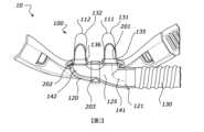
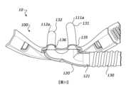
根據本文所揭露的實施方式中的至少一個的某些特徵、方面和優點,提供了一種鼻介面,該鼻介面包括:第一鼻叉,該第一鼻叉具有第一基部和第一終端端部;第二鼻叉,該第二鼻叉具有第二基部和第二終端端部;氣體歧管,該氣體歧管包括歧管腔室和氣體入口;以及定位在第一鼻叉、第二鼻叉或歧管腔室內的至少一個元件,其中,該至少一個元件被配置成增加行進通過第一鼻叉、第二鼻叉或歧管腔室中的至少一個的氣體流的阻力,並且其中,氣體入口與或被配置成與氣體輸送導管流體連通。In accordance with certain features, aspects, and advantages of at least one of the embodiments disclosed herein, a nasal interface is provided, comprising: a first nasal prong having a first base and a first terminal end; a second nasal prong having a second base and a second terminal end; a gas manifold comprising a manifold chamber and a gas inlet; and at least one element positioned within the first nasal prong, the second nasal prong, or the manifold chamber, wherein the at least one element is configured to increase resistance to gas flow traveling through at least one of the first nasal prong, the second nasal prong, or the manifold chamber, and wherein the gas inlet is in fluid communication with or is configured to be in fluid communication with a gas transport duct.
根據本文所揭露的實施方式中的至少一個的某些特徵、方面和優點,提供了一種鼻介面,該鼻介面包括:第一鼻叉,該第一鼻叉具有第一基部和第一終端端部;第二鼻叉,該第二鼻叉具有第二基部和第二終端端部;氣體歧管,該氣體歧管包括歧管腔室和氣體入口;以及定位在第二鼻叉內的第二鼻叉元件,其中,該第二鼻叉元件被配置成增加行進通過第二鼻叉的氣體流的流動阻力,並且其中,氣體入口與或被配置成與氣體輸送導管流體連通。According to certain features, aspects and advantages of at least one of the embodiments disclosed herein, a nasal interface is provided, comprising: a first nasal prong having a first base and a first terminal end; a second nasal prong having a second base and a second terminal end; a gas manifold comprising a manifold chamber and a gas inlet; and a second nasal prong element positioned within the second nasal prong, wherein the second nasal prong element is configured to increase the flow resistance of a gas flow traveling through the second nasal prong, and wherein the gas inlet is in fluid communication with or is configured to be in fluid communication with a gas transport duct.
根據本文所揭露的實施方式中的至少一個的某些特徵、方面和優點,提供了一種鼻介面,該鼻介面包括:第一鼻叉,該第一鼻叉具有第一基部和第一終端端部;第二鼻叉,該第二鼻叉具有第二基部和第二終端端部;氣體歧管,該氣體歧管包括歧管腔室和氣體入口;以及定位在歧管腔室內的歧管元件,其中,該歧管元件被配置成增加行進通過歧管腔室並到達第一鼻叉或第二鼻叉中的至少一個的氣體流的阻力,並且其中,氣體入口與或被配置成與氣體輸送導管流體連通。In accordance with certain features, aspects, and advantages of at least one of the embodiments disclosed herein, a nasal interface is provided, comprising: a first nasal prong having a first base and a first terminal end; a second nasal prong having a second base and a second terminal end; a gas manifold comprising a manifold chamber and a gas inlet; and a manifold element positioned within the manifold chamber, wherein the manifold element is configured to increase resistance to a gas flow traveling through the manifold chamber and reaching at least one of the first nasal prong or the second nasal prong, and wherein the gas inlet is in fluid communication with or is configured to be in fluid communication with a gas transport duct.
在一些組態中,氣體流的阻力的增加被配置成引起第一鼻叉和第二鼻叉處的不對稱氣體流。In some configurations, the increase in resistance to gas flow is configured to cause asymmetric gas flow at the first nasal prong and the second nasal prong.
在一些組態中,第一鼻叉、第二鼻叉、歧管腔室和氣體入口彼此流體連通。In some configurations, the first nasal prong, the second nasal prong, the manifold chamber, and the gas inlet are fluidly connected to each other.
在一些組態中,該至少一個元件係定位在第二鼻叉內的第二鼻叉元件。In some configurations, the at least one element is a second nose fork element positioned within the second nose fork.
在一些組態中,第二鼻叉元件被配置成增加行進通過第二鼻叉的氣體流的阻力。In some configurations, the second nose prong element is configured to increase resistance to gas flow traveling through the second nose prong.
在一些組態中,第二鼻叉元件定位在第二基部處。In some configurations, the second nose fork element is positioned at the second base.
在一些組態中,第二鼻叉的基部包括由第二鼻叉的壁形成的流動通路的入口。In some configurations, the base of the second nasal prong includes an entrance to a flow passage formed by a wall of the second nasal prong.
在一些組態中,鼻介面包括歧管元件,其中,該歧管元件定位在氣體歧管的歧管腔室內。In some configurations, the nasal interface includes a manifold element, wherein the manifold element is positioned within a manifold chamber of the gas manifold.
在一些組態中,歧管元件被配置成增加行進通過歧管腔室的氣體流的流動阻力。In some configurations, the manifold element is configured to increase flow resistance to a gas flow traveling through the manifold chamber.
在一些組態中,氣體流係基本上沿從氣體歧管入口穿過氣體歧管腔室並進入第一鼻叉和/或第二鼻叉的流動通路中的方向。In some configurations, the gas flow is substantially in a direction from the gas manifold inlet through the gas manifold chamber and into the flow path of the first nose prong and/or the second nose prong.
在一些組態中,歧管元件基本上定位在歧管腔室的中心。In some configurations, the manifold element is positioned substantially in the center of the manifold chamber.
在一些組態中,鼻介面包括第一鼻叉元件,其中,該第一鼻叉元件定位在第一鼻叉內。In some configurations, the nasal interface includes a first nasal prong element, wherein the first nasal prong element is positioned within the first nasal prong.
在一些組態中,第一鼻叉元件被配置成增加行進通過第一鼻叉的氣體流的流動阻力。In some configurations, the first nasal prong element is configured to increase flow resistance to a gas flow traveling through the first nasal prong.
在一些組態中,第一鼻叉元件定位在第一鼻叉的基部處。In some configurations, the first nasal fork element is positioned at the base of the first nasal fork.
在一些組態中,第一鼻叉元件提供的氣體流的阻力與第二鼻叉元件提供的氣體流的阻力不同。In some configurations, the resistance to gas flow provided by the first nose prong element is different from the resistance to gas flow provided by the second nose prong element.
在一些組態中,氣體輸送導管位於患者導管與氣體入口之間。In some configurations, the gas delivery catheter is located between the patient catheter and the gas inlet.
在一些組態中,氣體歧管與氣體輸送導管一體地形成或聯接至氣體輸送導管。In some configurations, the gas manifold is integrally formed with or coupled to the gas delivery conduits.
在一些組態中,氣體歧管包括歧管寬度,並且其中,該歧管寬度與第一鼻叉或第二鼻叉中的至少一個的內直徑一樣大或大於該內直徑。In some configurations, the gas manifold includes a manifold width, and wherein the manifold width is the same as or greater than an inner diameter of at least one of the first nasal prong or the second nasal prong.
在一些組態中,鼻介面包括插管本體,該插管本體包括第一鼻叉和第二鼻叉,並且其中,該插管本體的在第一鼻叉與第二鼻叉之間的外表面包括凹陷部(dip),以容納患者的鼻子的一部分並減小所容納部分的底側上的壓力。In some configurations, the nasal interface includes a cannula body comprising a first nasal prong and a second nasal prong, and wherein an outer surface of the cannula body between the first nasal prong and the second nasal prong includes a dip to accommodate a portion of the patient's nose and reduce pressure on the bottom side of the accommodated portion.
在一些組態中,第一鼻叉或第二鼻叉中的至少一個的大小被確定為在該至少一個鼻叉的外表面與患者的皮膚之間維持足夠的間隙,以避免密封鼻介面與患者之間的氣體路徑。In some configurations, at least one of the first nasal prong or the second nasal prong is sized to maintain a sufficient gap between an outer surface of the at least one nasal prong and the patient's skin to avoid sealing a gas path between the nasal interface and the patient.
在一些組態中,至少第一鼻叉或第二鼻叉由彈性材料製成,該彈性材料使得第一鼻叉能夠在使用中響應於溫度和與患者的鼻孔的接觸而變形並設定其形狀。In some configurations, at least the first nasal prong or the second nasal prong is made of an elastic material that enables the first nasal prong to deform and set its shape in response to temperature and contact with the patient's nostrils during use.
在一些組態中,第一鼻叉或第二鼻叉中的至少一個不是由矽樹脂製成的。In some configurations, at least one of the first nasal prong or the second nasal prong is not made of silicone.
在一些組態中,第一鼻叉或第二鼻叉中的至少一個由熱塑性彈性體制成。In some configurations, at least one of the first nasal prong or the second nasal prong is made of a thermoplastic elastomer.
在一些組態中,鼻介面被配置成在患者的鼻孔處引起不對稱氣體流。In some configurations, the nasal interface is configured to induce asymmetric gas flow at the patient's nostrils.
在一些組態中,氣體歧管包括流動通道,該流動通道的氣體流動方向基本上垂直於穿過第一鼻叉和第二鼻叉的氣體流動路徑。In some configurations, the gas manifold includes a flow channel having a gas flow direction substantially perpendicular to a gas flow path through the first nose prong and the second nose prong.
在一些組態中,歧管元件包括用於使氣體流通過的歧管孔口,其中,所述歧管孔口的截面開口小於用於氣體流的歧管腔室。In some configurations, the manifold element includes a manifold orifice for passing gas therethrough, wherein the cross-sectional opening of the manifold orifice is smaller than the manifold chamber for the gas flow.
在一些組態中,第二鼻叉包括用於使氣體流通過的第二孔口,其中,所述第二孔口的截面開口小於用於氣體流的第二鼻叉。In some configurations, the second nasal prong includes a second orifice for passing gas therethrough, wherein the cross-sectional opening of the second orifice is smaller than that of the second nasal prong for gas flow.
在一些組態中,歧管孔口和/或第二孔口形成在板或壁中。In some configurations, the manifold port and/or the second port are formed in a plate or a wall.
在一些組態中,板或壁具有入口表面和出口表面,其中歧管孔口和/或第二歧管形成在該入口表面與該出口表面之間。In some configurations, the plate or wall has an inlet surface and an outlet surface, wherein a manifold aperture and/or a second manifold is formed between the inlet surface and the outlet surface.
在一些組態中,氣體流係沿從入口表面穿過歧管孔口和/或第二孔口到達出口表面的方向。In some configurations, the gas flow is in a direction from the inlet surface through the manifold orifice and/or the second orifice to the outlet surface.
在一些組態中,出口表面與歧管孔口和/或第二孔口之間的過渡部係錐形的。In some configurations, the transition between the outlet surface and the manifold orifice and/or the second orifice is tapered.
在一些組態中,入口表面與歧管孔口和/或第二孔口之間的過渡部係基本上直角的。In some configurations, the transition between the inlet surface and the manifold orifice and/or the second orifice is substantially right angled.
在一些組態中,入口表面與歧管孔口和/或第二孔口之間的過渡部係錐形的,其中,出口表面的錐角大於入口表面的錐角。In some configurations, the transition between the inlet surface and the manifold orifice and/or the second orifice is tapered, wherein the taper angle of the outlet surface is greater than the taper angle of the inlet surface.
在一些組態中,入口表面與歧管孔口和/或第二孔口之間的過渡部係基本上尖角。In some configurations, the transition between the inlet surface and the manifold orifice and/or the second orifice is substantially sharp.
在一些組態中,該至少一個歧管孔口和/或第二孔口係豎直地縱長延伸穿過板或壁的間隙、切口或狹縫。In some configurations, the at least one manifold opening and/or the second opening extends vertically through a gap, cutout or slit in a plate or wall.
在一些組態中,該至少一個歧管孔口和/或第二孔口係水平地縱長延伸穿過板或壁的間隙、切口或狹縫。In some configurations, the at least one manifold opening and/or the second opening extends horizontally and longitudinally through a gap, cutout or slit in a plate or wall.
在一些組態中,該至少一個歧管孔口和/或第二孔口係基本上圓形的穿孔。In some configurations, the at least one manifold opening and/or the second opening is a substantially circular through-hole.
在一些組態中,該至少一個歧管孔口和/或第二孔口包括穿孔圖案。In some configurations, the at least one manifold port and/or the second port comprises a perforated pattern.
在一些組態中,該至少一個歧管孔口和/或第二孔口的板或壁包括多孔介質。In some configurations, the plate or wall of at least one manifold port and/or the second port comprises a porous medium.
在一些組態中,第二鼻叉元件和/或歧管元件和/或第一鼻叉元件中的任何一個或多個包括閥。In some configurations, any one or more of the second nose fork element and/or the manifold element and/or the first nose fork element includes a valve.
在一些組態中,閥被配置成僅在閾值壓力或流速下打開。In some configurations, the valve is configured to open only at a threshold pressure or flow rate.
在一些組態中,閥被配置成向流動路徑中提供限定的壓降。In some configurations, the valve is configured to provide a defined pressure drop into the flow path.
在一些組態中,閥係鴨嘴閥。In some configurations, the valve is a duckbill valve.
在一些組態中,第二鼻叉元件和/或歧管元件和/或第一鼻叉元件中的任何一個或多個包括噴嘴。In some configurations, any one or more of the second nose fork element and/or the manifold element and/or the first nose fork element includes a nozzle.
在一些組態中,噴嘴被配置成向流動路徑中提供限定的壓降。In some configurations, the nozzle is configured to provide a defined pressure drop into the flow path.
在一些組態中,歧管元件被配置成經由手動致動進行調節,以增加或減小該元件的限制程度。In some configurations, the manifold element is configured to be adjusted via manual actuation to increase or decrease the degree of restriction of the element.
在一些組態中,歧管元件被配置成可沿上游-下游方向可滑動地移動。In some configurations, the manifold element is configured to be slidably movable in an upstream-downstream direction.
在一些組態中,其中,歧管元件包括帶有螺旋螺紋的可旋轉件。In some configurations, the manifold element includes a rotatable member having a helical thread.
在一些組態中,歧管元件進一步包括在鼻介面的氣體歧管外部的一部分。In some configurations, the manifold element further includes a portion of the gas manifold external to the nasal interface.
在一些組態中,歧管元件被配置成可旋轉地移動,使得當旋轉外部部分時,歧管元件豎直地平移進入或離開歧管腔室流動路徑,由此分別增加或減小所述流動路徑中的流量限制程度。In some configurations, the manifold element is configured to be rotationally movable such that when the outer portion is rotated, the manifold element translates vertically into or out of the manifold chamber flow path, thereby increasing or decreasing the degree of flow restriction in the flow path, respectively.
在一些組態中,氣體歧管包括位於壁處的開口,該開口與歧管的氣體入口近似相對和/或與第二鼻叉的第二基部近似相對。In some configurations, the gas manifold includes an opening located in the wall that is approximately opposite the gas inlet of the manifold and/or approximately opposite the second base of the second nose prong.
在一些組態中,該開口包括一個或多個孔口。In some configurations, the opening includes one or more orifices.
在一些組態中,其中,所述孔口的數量和直徑被配置成提供限定的壓降。In some configurations, the number and diameter of the orifices are configured to provide a defined pressure drop.
在一些組態中,歧管的壁中的開口氣動地連接至被配置成提供限定的壓降的部件。In some configurations, the openings in the wall of the manifold are pneumatically connected to components configured to provide a defined pressure drop.
在一些組態中,該部件係多孔介質、噴嘴、壓力釋放閥或氣泡式CPAP鼓泡腔室中的至少一個。In some configurations, the component is at least one of a porous media, a nozzle, a pressure release valve, or a bubble CPAP bubbling chamber.
在一些組態中,氣體入口的軸線相對於第一鼻叉或第二鼻叉中的至少一個的軸線係同軸的。In some configurations, the axis of the gas inlet is coaxial with respect to the axis of at least one of the first nose prong or the second nose prong.
在一些組態中,氣體入口的軸線的角度相對於第一鼻叉或第二鼻叉中的至少一個的軸線係成直角的。In some configurations, the angle of the axis of the gas inlet is at right angles to the axis of at least one of the first nose prong or the second nose prong.
在一些組態中,鼻介面包括輔助氣體入口,以引起或促成第一鼻叉和第二鼻叉處的不對稱氣體流。In some configurations, the nasal interface includes an auxiliary gas inlet to induce or facilitate asymmetric gas flow at the first nasal prong and the second nasal prong.
在一些組態中,輔助氣體入口終止於第一鼻叉或第二鼻叉中。In some configurations, the auxiliary gas inlet terminates in the first nose prong or the second nose prong.
在一些組態中,輔助氣體導管包括入口並終止於第一鼻叉或第二鼻叉中的入口處。In some configurations, the auxiliary gas conduit includes an inlet and terminates at an inlet in the first nasal prong or the second nasal prong.
在一些組態中,輔助氣體入口與輔助氣體輸送導管流體連通。In some configurations, the auxiliary gas inlet is in fluid communication with the auxiliary gas delivery conduit.
在一些組態中,氣體入口或氣體輸送導管中的至少一個包括具有第一內部截面積的管腔,並且輔助氣體入口或輔助氣體輸送導管中的至少一個包括具有第二內部截面積的管腔。In some configurations, at least one of the gas inlet or the gas delivery conduit includes a lumen having a first internal cross-sectional area, and at least one of the auxiliary gas inlet or the auxiliary gas delivery conduit includes a lumen having a second internal cross-sectional area.
在一些組態中,第一內部截面積和第二內部截面積中的一個或兩個係基本上圓形的。In some configurations, one or both of the first interior cross-sectional area and the second interior cross-sectional area are substantially circular.
在一些組態中,第一內部截面積和第二內部截面積係不同的。In some configurations, the first interior cross-sectional area and the second interior cross-sectional area are different.
在一些組態中,第二內部截面積小於第一鼻叉或第二鼻叉的內部截面積。In some configurations, the second internal cross-sectional area is smaller than the internal cross-sectional area of the first nose fork or the second nose fork.
在一些組態中,氣體輸送導管和輔助氣體輸送導管設置在歧管腔室的同一側上。In some configurations, the gas delivery conduit and the auxiliary gas delivery conduit are disposed on the same side of the manifold chamber.
在一些組態中,輔助氣體輸送導管定位在氣體輸送導管中。In some configurations, an auxiliary gas delivery conduit is positioned within the gas delivery conduit.
在一些組態中,氣體入口或氣體輸送導管中的至少一個包括第一長度,並且輔助氣體入口或輔助氣體輸送導管中的至少一個包括第二長度。In some configurations, at least one of the gas inlet or the gas delivery conduit includes a first length, and at least one of the auxiliary gas inlet or the auxiliary gas delivery conduit includes a second length.
在一些組態中,第一長度和第二長度係不相等的,以引起或促成第一鼻叉和第二鼻叉處的不對稱氣體流。In some configurations, the first length and the second length are unequal to cause or facilitate asymmetric gas flow at the first nasal prong and the second nasal prong.
在一些組態中,第一長度長於第二長度,以引起或促成第一鼻叉和第二鼻叉處的不對稱氣體流。In some configurations, the first length is longer than the second length to cause or promote asymmetric gas flow at the first nose prong and the second nose prong.
在一些組態中,第一長度短於第二長度,以引起或促成第一鼻叉和第二鼻叉處的不對稱氣體流。In some configurations, the first length is shorter than the second length to cause or promote asymmetric gas flow at the first nasal prong and the second nasal prong.
在一些組態中,氣體輸送導管與第一氣體流連通,並且輔助氣體輸送導管與第二氣體流連通。In some configurations, the gas delivery conduit is in communication with a first gas flow, and the auxiliary gas delivery conduit is in communication with a second gas flow.
在一些組態中,第一氣體流的流速不同於第二氣體流的流速。In some configurations, the flow rate of the first gas flow is different from the flow rate of the second gas flow.
在一些組態中,氣體歧管與第一氣體流之間的所得流動方向係不同於氣體歧管與第二氣體流之間的所得流動方向的流動方向。In some configurations, a resulting flow direction between the gas manifold and the first gas flow is a flow direction different from a resulting flow direction between the gas manifold and the second gas flow.
在一些組態中,第一氣體流或第二氣體流中的一個係吸入流。In some configurations, one of the first gas flow or the second gas flow is an intake flow.
在一些組態中,第一氣體流的氣體壓力不同於第二氣體流的氣體壓力。In some configurations, the gas pressure of the first gas flow is different from the gas pressure of the second gas flow.
在一些組態中,相對於環境的負氣體壓力由第一氣體流或第二氣體流形成。In some configurations, a negative gas pressure relative to the environment is formed by the first gas flow or the second gas flow.
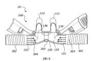
根據本文所揭露的實施方式中的至少一個的某些特徵、方面和優點,提供了一種鼻介面,該鼻介面包括:第一鼻叉,該第一鼻叉具有第一基部和第一終端端部;第二鼻叉,該第二鼻叉具有第二基部和第二終端端部;以及氣體歧管,該氣體歧管包括:歧管腔室;第一氣體入口;以及第二氣體入口,其中,第一氣體入口和第二氣體入口設置在歧管腔室的相對端部上並且分別與第一氣體輸送導管和第二氣體輸送導管流體連通。According to certain features, aspects and advantages of at least one of the embodiments disclosed herein, a nasal interface is provided, which includes: a first nasal fork having a first base and a first terminal end; a second nasal fork having a second base and a second terminal end; and a gas manifold, which includes: a manifold chamber; a first gas inlet; and a second gas inlet, wherein the first gas inlet and the second gas inlet are arranged on opposite ends of the manifold chamber and are respectively connected to the first gas transport duct and the second gas transport duct fluid.
根據本文所揭露的實施方式中的至少一個的某些特徵、方面和優點,提供了一種鼻介面,該鼻介面包括:第一鼻叉,該第一鼻叉具有第一基部和第一終端端部;第二鼻叉,該第二鼻叉具有第二基部和第二終端端部;以及氣體歧管,該氣體歧管包括:歧管腔室;第一氣體入口;第二氣體入口,其中,第一氣體入口和第二氣體入口分別與第一氣體輸送導管和第二氣體輸送導管流體連通,其中,鼻介面被配置成引起第一鼻叉和第二鼻叉處的不對稱氣體流。According to certain features, aspects and advantages of at least one of the embodiments disclosed herein, a nasal interface is provided, comprising: a first nasal fork having a first base and a first terminal end; a second nasal fork having a second base and a second terminal end; and a gas manifold comprising: a manifold chamber; a first gas inlet; a second gas inlet, wherein the first gas inlet and the second gas inlet are fluidly connected to a first gas transport duct and a second gas transport duct, respectively, wherein the nasal interface is configured to cause asymmetric gas flow at the first nasal fork and the second nasal fork.
在一些組態中,第一氣體入口和第二氣體入口設置在歧管腔室的相對側上。In some configurations, the first gas inlet and the second gas inlet are disposed on opposite sides of the manifold chamber.
在一些組態中,第一氣體入口比第二入口更靠近第一鼻叉,並且其中,第二入口比第一入口更靠近第二鼻叉。In some configurations, the first gas inlet is closer to the first nasal prong than the second inlet, and wherein the second inlet is closer to the second nasal prong than the first inlet.
在一些組態中,第一氣體入口和第一氣體輸送導管中的至少一個形成為整體結構,或者第二氣體入口和第二氣體輸送導管形成為整體結構。In some configurations, at least one of the first gas inlet and the first gas delivery conduit is formed as an integral structure, or the second gas inlet and the second gas delivery conduit is formed as an integral structure.
在一些組態中,第一氣體輸送導管與第一氣體流連通,並且第二氣體輸送導管與第二氣體流連通。In some configurations, the first gas delivery conduit is in communication with a first gas flow, and the second gas delivery conduit is in communication with a second gas flow.
在一些組態中,第一氣體流的流速不同於第二氣體流的流速。In some configurations, the flow rate of the first gas flow is different from the flow rate of the second gas flow.
在一些組態中,氣體歧管與第一氣體流之間的所得流動方向係不同於氣體歧管與第二氣體流之間的所得流動方向的流動方向。In some configurations, a resulting flow direction between the gas manifold and the first gas flow is a flow direction different from a resulting flow direction between the gas manifold and the second gas flow.
在一些組態中,第一氣體流或第二氣體流中的一個係吸入流。In some configurations, one of the first gas flow or the second gas flow is an intake flow.
在一些組態中,第一氣體流的氣體壓力不同於第二氣體流的氣體壓力。In some configurations, the gas pressure of the first gas flow is different from the gas pressure of the second gas flow.
在一些組態中,相對於環境的負氣體壓力由第一氣體流或第二氣體流形成。In some configurations, a negative gas pressure relative to the environment is formed by the first gas flow or the second gas flow.
在一些組態中,第一鼻叉、第二鼻叉、歧管腔室、第一氣體入口和第二氣體入口彼此流體連通。In some configurations, the first nasal prong, the second nasal prong, the manifold chamber, the first gas inlet, and the second gas inlet are fluidly connected to each other.
在一些組態中,鼻介面包括流量變更特徵,該流量變更特徵被配置成引起第一鼻叉和第二鼻叉處的不對稱氣體流。In some configurations, the nasal interface includes a flow changing feature configured to cause asymmetric gas flow at the first nasal prong and the second nasal prong.
在一些組態中,其中,第一入口和/或第一氣體輸送導管包括具有第一內部截面積的管腔,並且第二入口和/或第二氣體輸送導管包括具有第二內部截面積的管腔,以引起第一鼻叉和第二鼻叉處的不對稱氣體流。In some configurations, wherein the first inlet and/or the first gas delivery conduit comprises a lumen having a first internal cross-sectional area, and the second inlet and/or the second gas delivery conduit comprises a lumen having a second internal cross-sectional area, to induce asymmetric gas flow at the first nasal prong and the second nasal prong.
在一些組態中,第一內部截面積和第二內部截面積中的那一個或兩個係基本上圓形的。In some configurations, one or both of the first interior cross-sectional area and the second interior cross-sectional area are substantially circular.
在一些組態中,第一內部截面積和第二內部截面積中的那一個或兩個係基本上非圓形的。In some configurations, one or both of the first interior cross-sectional area and the second interior cross-sectional area are substantially non-circular.
在一些組態中,第一內部截面積和第二內部截面積係不相等的,以引起第一鼻叉和第二鼻叉處的不對稱氣體流。In some configurations, the first internal cross-sectional area and the second internal cross-sectional area are unequal to cause asymmetric gas flow at the first nose prong and the second nose prong.
在一些組態中,第一內部截面積大於第二內部截面積,以引起第一鼻叉和第二鼻叉處的不對稱氣體流。In some configurations, the first internal cross-sectional area is larger than the second internal cross-sectional area to cause asymmetric gas flow at the first nose prong and the second nose prong.
在一些組態中,第一內部截面積小於第二內部截面積,以引起第一鼻叉和第二鼻叉處的不對稱氣體流。In some configurations, the first internal cross-sectional area is smaller than the second internal cross-sectional area to cause asymmetric gas flow at the first nose prong and the second nose prong.
在一些組態中,第一入口和/或第一氣體輸送導管包括第一長度,並且第二入口和/或第二氣體輸送導管包括第二長度,以引起第一鼻叉和第二鼻叉處的不對稱氣體流。In some configurations, the first inlet and/or the first gas delivery conduit includes a first length, and the second inlet and/or the second gas delivery conduit includes a second length to cause asymmetric gas flow at the first nasal prong and the second nasal prong.
在一些組態中,第一長度和第二長度係不相等的,以引起第一鼻叉和第二鼻叉處的不對稱氣體流。In some configurations, the first length and the second length are unequal to cause asymmetric gas flow at the first nasal prong and the second nasal prong.
在一些組態中,第一長度長於第二長度,以引起第一鼻叉和第二鼻叉處的不對稱氣體流。In some configurations, the first length is longer than the second length to cause asymmetric gas flow at the first nasal prong and the second nasal prong.
在一些組態中,第一長度短於第二長度,以引起第一鼻叉和第二鼻叉處的不對稱氣體流。In some configurations, the first length is shorter than the second length to cause asymmetric gas flow at the first nasal prong and the second nasal prong.
在一些組態中,第一入口和/或第一氣體輸送導管的內表面包括第一浮雕特徵圖案。In some configurations, the inner surface of the first inlet and/or the first gas delivery conduit includes a first relief feature pattern.
在一些組態中,第二入口和/或第二氣體輸送導管的內表面包括第二浮雕特徵圖案。In some configurations, the inner surface of the second inlet and/or the second gas delivery conduit includes a second embossed feature pattern.
在一些組態中,第一浮雕特徵圖案比第二浮雕特徵圖案顯著更粗糙,以引起第一鼻叉和第二鼻叉處的不對稱氣體流。In some configurations, the first relief feature pattern is significantly rougher than the second relief feature pattern to induce asymmetric gas flow at the first nasal prong and the second nasal prong.
在一些組態中,其中,第一浮雕特徵圖案比第二浮雕特徵圖案顯著更光滑,以引起第一鼻叉和第二鼻叉處的不對稱氣體流。In some configurations, the first relief feature pattern is significantly smoother than the second relief feature pattern to induce asymmetric gas flow at the first nasal prong and the second nasal prong.
在一些組態中,浮雕特徵圖案包括以下中的一個或多個:凹坑、突起、肋和/或翅片。In some configurations, the relief feature pattern includes one or more of: dimples, protrusions, ribs, and/or fins.
在一些組態中,第一氣體入口和第二氣體入口中的那一個或兩個的軸線相對於第一鼻叉或第二鼻叉中的至少一個的軸線係同軸的。In some configurations, the axis of one or both of the first gas inlet and the second gas inlet is coaxial with respect to the axis of at least one of the first nose prong or the second nose prong.
在一些組態中,第一氣體入口和/或第二氣體入口的軸線的角度相對於第一鼻叉或第二鼻叉中的至少一個的軸線係成直角的。In some configurations, the angle of the axis of the first gas inlet and/or the second gas inlet is at right angles to the axis of at least one of the first nose prong or the second nose prong.
在一些組態中,鼻介面包括以下各者中的至少一個:(i) 第一鼻叉元件,其定位在第一鼻叉內;(ii) 第二鼻叉元件,其定位在第二鼻叉內;(iii) 歧管元件,其定位在歧管腔室中並且在第一鼻叉的第一基部與第二鼻叉的第二基部之間;(iv) 第一氣體入口元件,其定位在氣體歧管的第一氣體入口處;或 (v) 第二氣體入口元件,其定位在氣體歧管的第二氣體入口處,其中,第一鼻叉元件、第二鼻叉元件、歧管元件、第一氣體入口元件和/或第二氣體入口元件均被配置成增加進入所述相應元件的氣體流的流動阻力,以引起第一鼻叉和第二鼻叉處的不對稱氣體流。In some configurations, the nasal interface includes at least one of the following: (i) a first nasal prong element positioned within the first nasal prong; (ii) a second nasal prong element positioned within the second nasal prong; (iii) a manifold element positioned in the manifold chamber and between a first base of the first nasal prong and a second base of the second nasal prong; (iv) a first gas inlet element positioned at a first gas inlet of the gas manifold; or (v) a second gas inlet element positioned at a second gas inlet of the gas manifold, wherein the first nasal prong element, the second nasal prong element, the manifold element, the first gas inlet element and/or the second gas inlet element are each configured to increase the flow resistance of the gas flow entering the corresponding element to cause asymmetric gas flow at the first nasal prong and the second nasal prong.
在一些組態中,鼻介面包括第一氣體入口元件和第二氣體入口元件,該第一氣體入口元件和該第二氣體入口元件均被配置成增加分別穿過第一氣體入口和第二氣體入口進入歧管的氣體流的流動阻力。In some configurations, the nasal interface includes a first gas inlet element and a second gas inlet element, each of which is configured to increase flow resistance to a gas flow entering the manifold through the first gas inlet and the second gas inlet, respectively.
在一些組態中,鼻介面包括第一鼻叉元件和第二鼻叉元件,該第一鼻叉元件和該第二鼻叉元件均被配置成增加分別進入第一鼻叉和第二鼻叉的氣體流的流動阻力。In some configurations, the nasal interface includes a first nasal prong element and a second nasal prong element, and the first nasal prong element and the second nasal prong element are both configured to increase the flow resistance of the gas flow entering the first nasal prong and the second nasal prong, respectively.
在一些組態中,鼻介面包括歧管元件和第一氣體入口元件,該歧管元件和該第一氣體入口元件均被配置成增加分別穿過歧管元件和第一氣體入口元件在歧管腔室內和進入歧管的氣體流的流動阻力。In some configurations, the nasal interface includes a manifold element and a first gas inlet element, each of which is configured to increase flow resistance to gas flow passing through the manifold element and the first gas inlet element within the manifold chamber and into the manifold, respectively.
在一些組態中,鼻介面包括歧管元件和第二氣體入口元件,該歧管元件和該第二氣體入口元件均被配置成增加分別穿過歧管元件和第二氣體入口元件在歧管腔室內和進入歧管的氣體流的流動阻力。In some configurations, the nasal interface includes a manifold element and a second gas inlet element, each of which is configured to increase flow resistance to gas flow passing through the manifold element and the second gas inlet element within the manifold chamber and into the manifold, respectively.
在一些組態中,第一鼻叉元件、第二鼻叉元件、歧管元件、第一氣體入口元件或第二氣體入口元件中的至少一個包括用於減少氣體流的通過的孔口。In some configurations, at least one of the first nasal prong element, the second nasal prong element, the manifold element, the first gas inlet element, or the second gas inlet element includes an orifice for reducing the passage of gas flow.
在一些組態中,其中,所述孔口的截面開口小於用於第一鼻叉、第二鼻叉或歧管腔室的流動通道或者用於氣體流的第一管腔或第二管腔中的至少一個。In some configurations, the cross-sectional opening of the orifice is smaller than the flow channel for the first nasal prong, the second nasal prong, or the manifold chamber, or at least one of the first lumen or the second lumen for gas flow.
在一些組態中,孔口形成在板或壁中。In some configurations, the orifice is formed in a plate or wall.
在一些組態中,板或壁具有入口表面和出口表面,其中孔口形成在該入口表面與該出口表面之間。In some configurations, the plate or wall has an inlet surface and an outlet surface, wherein an orifice is formed between the inlet surface and the outlet surface.
在一些組態中,氣體流係沿從入口表面穿過孔口到達出口表面的方向。In some configurations, gas flow is in a direction from the inlet surface through the orifice to the outlet surface.
在一些組態中,出口表面與孔口之間的過渡部係錐形的。In some configurations, the transition between the outlet surface and the orifice is tapered.
在一些組態中,入口表面與孔口之間的過渡部係基本上直角的。In some configurations, the transition between the inlet surface and the orifice is substantially right angled.
在一些組態中,入口表面與孔口之間的過渡部係錐形的,其中,出口表面的錐角大於入口表面的錐角。In some configurations, the transition between the inlet surface and the orifice is tapered, wherein the taper angle of the outlet surface is greater than the taper angle of the inlet surface.
在一些組態中,入口表面與孔口之間的過渡部係基本上尖角。In some configurations, the transition between the inlet surface and the orifice is substantially sharp.
在一些組態中,該至少一個孔口係豎直地縱長延伸穿過板或壁的間隙、切口或狹縫。In some configurations, the at least one aperture extends vertically through a gap, cut or slit in a plate or wall.
在一些組態中,該至少一個孔口係水平地縱長延伸穿過板或壁的間隙、切口或狹縫。In some configurations, the at least one aperture extends horizontally and longitudinally through a gap, cutout or slit in a plate or wall.
在一些組態中,該至少一個孔口係基本上圓形的穿孔。In some configurations, the at least one orifice is a substantially circular through-hole.
在一些組態中,該至少一個孔口包括穿孔圖案。In some configurations, the at least one aperture comprises a perforated pattern.
在一些組態中,該至少一個孔口的板或壁包括多孔介質。In some configurations, the plate or wall of the at least one orifice comprises a porous medium.
在一些組態中,第一鼻叉元件、第二鼻叉元件、歧管元件、第一氣體元件或第二氣體元件中的至少一個包括閥。In some configurations, at least one of the first nasal prong element, the second nasal prong element, the manifold element, the first gas element, or the second gas element includes a valve.
在一些組態中,閥被配置成僅在閾值壓力或流速下打開。In some configurations, the valve is configured to open only at a threshold pressure or flow rate.
在一些組態中,閥被配置成向流動路徑中提供限定的壓降。In some configurations, the valve is configured to provide a defined pressure drop into the flow path.
在一些組態中,閥係鴨嘴閥。In some configurations, the valve is a duckbill valve.
在一些組態中,第一鼻叉元件、第二鼻叉元件、歧管元件、第一氣體元件或第二氣體元件中的至少一個包括噴嘴。In some configurations, at least one of the first nose prong element, the second nose prong element, the manifold element, the first gas element, or the second gas element includes a nozzle.
在一些組態中,噴嘴被配置成向流動路徑中提供限定的壓降。In some configurations, the nozzle is configured to provide a defined pressure drop into the flow path.
在一些組態中,第一鼻叉元件、第二鼻叉元件、歧管元件、第一氣體元件或第二氣體元件中的至少一個被配置成經由手動致動進行調節,以增加或減小該元件的限制程度。In some configurations, at least one of the first nasal prong element, the second nasal prong element, the manifold element, the first gas element, or the second gas element is configured to be adjusted via manual actuation to increase or decrease the degree of restriction of the element.
在一些組態中,該元件被配置成可沿上游-下游方向可滑動地移動。In some configurations, the element is configured to be slidably movable in an upstream-downstream direction.
在一些組態中,該元件包括帶有螺旋螺紋的可旋轉件。In some configurations, the element includes a rotatable member having a helical thread.
在一些組態中,該元件進一步包括在鼻介面外部的一部分。In some configurations, the element further includes a portion external to the nasal interface.
在一些組態中,該元件被配置成可旋轉地移動,使得當旋轉外部部分時,該元件豎直地平移進入或離開流動路徑,由此分別增加或減小所述流動路徑中的流量限制程度。In some configurations, the element is configured to be rotationally movable such that when the outer portion is rotated, the element translates vertically into or out of the flow path, thereby increasing or decreasing the degree of flow restriction in the flow path, respectively.
根據本文所揭露的實施方式中的至少一個的某些特徵、方面和優點,提供了一種鼻介面,該鼻介面包括:第一鼻叉和第二鼻叉;氣體歧管,該氣體歧管包括歧管腔室和氣體入口,該氣體入口與或被配置成與氣體輸送導管流體連通;以及至少一個導流元件,其中,該至少一個導流元件被配置成將氣體流從氣體入口引導至第一鼻叉或第二鼻叉中的一個以產生不對稱的氣體流。According to certain features, aspects and advantages of at least one of the embodiments disclosed herein, a nasal interface is provided, comprising: a first nasal prong and a second nasal prong; a gas manifold comprising a manifold chamber and a gas inlet, the gas inlet being connected to or configured to be connected to a gas transport duct fluid; and at least one flow-guiding element, wherein the at least one flow-guiding element is configured to guide the gas flow from the gas inlet to one of the first nasal prong or the second nasal prong to produce an asymmetric gas flow.
在一些組態中,該至少一個導流元件係氣體入口。In some configurations, the at least one flow-guiding element is a gas inlet.
根據本文所揭露的實施方式中的至少一個的某些特徵、方面和優點,提供了一種鼻介面,該鼻介面包括:第一鼻叉和第二鼻叉;氣體歧管,該氣體歧管包括歧管腔室和氣體入口,該氣體入口與或被配置成與氣體輸送導管流體連通;以及至少一個導流元件,該至少一個導流元件形成為歧管腔室、氣體入口或氣體輸送導管中的至少一個的一部分,其中,該至少一個導流元件被配置成將氣體流引導至第一鼻叉或第二鼻叉中的一個以產生不對稱的氣體流。According to certain features, aspects and advantages of at least one of the embodiments disclosed herein, a nasal interface is provided, comprising: a first nasal prong and a second nasal prong; a gas manifold comprising a manifold chamber and a gas inlet, the gas inlet being in fluid communication with or configured to be in fluid communication with a gas transport duct; and at least one flow-guiding element forming a part of at least one of the manifold chamber, the gas inlet or the gas transport duct, wherein the at least one flow-guiding element is configured to guide the gas flow to one of the first nasal prong or the second nasal prong to produce an asymmetric gas flow.
在一些組態中,第一鼻叉、第二鼻叉、歧管腔室和第一氣體入口彼此流體連通。In some configurations, the first nasal prong, the second nasal prong, the manifold chamber, and the first gas inlet are fluidly connected to each other.
在一些組態中,導流元件被配置成在使用中向第一鼻叉處提供較大的動態壓力並在使用中向第二鼻叉處提供較小的動態壓力,以產生不對稱的氣體流。In some configurations, the flow-guiding element is configured to provide a greater dynamic pressure to the first nasal prong during use and a smaller dynamic pressure to the second nasal prong during use to produce an asymmetric gas flow.
在一些組態中,第一鼻叉或第二鼻叉中的至少一個的大小被確定為在該至少一個鼻叉的外表面與患者的皮膚之間維持足夠的間隙,以避免密封鼻介面與患者之間的氣體路徑。In some configurations, at least one of the first nasal prong or the second nasal prong is sized to maintain a sufficient gap between an outer surface of the at least one nasal prong and the patient's skin to avoid sealing a gas path between the nasal interface and the patient.
在一些組態中,第一鼻叉和第二鼻叉與歧管腔室流體連通。In some configurations, the first nasal prong and the second nasal prong are in fluid communication with the manifold chamber.
在一些組態中,氣體入口定位在歧管腔室中、與第一鼻叉或第二鼻叉中的至少一個相對。In some configurations, the gas inlet is positioned in the manifold chamber opposite at least one of the first nasal prongs or the second nasal prongs.
在一些組態中,該至少一個導流元件定位在氣體歧管腔室內。In some configurations, the at least one flow directing element is positioned within the gas manifold chamber.
在一些組態中,該至少一個導流元件定位在氣體輸送導管內。In some configurations, the at least one flow-guiding element is positioned within the gas delivery conduit.
在一些組態中,該至少一個導流元件定位在氣體輸送導管內,其中氣體輸送導管與氣體入口相接。In some configurations, the at least one flow guiding element is positioned within a gas delivery conduit, wherein the gas delivery conduit is connected to the gas inlet.
在一些組態中,該至少一個導流元件包括至少一個傾斜突起,其中,該突起被配置成將氣體流從氣體入口引導朝向第一鼻叉或第二鼻叉中的一個。In some configurations, the at least one flow-guiding element comprises at least one inclined protrusion, wherein the protrusion is configured to direct the gas flow from the gas inlet toward one of the first nasal prong or the second nasal prong.
在一些組態中,該至少一個導流元件進一步包括第二傾斜突起,該第二傾斜突起在流動路徑中與第一突起相對定位並且同樣被配置成將氣體流從氣體入口引導朝向第一鼻叉或第二鼻叉中的一個。In some configurations, the at least one flow-guiding element further includes a second inclined protrusion that is positioned opposite the first protrusion in the flow path and is also configured to direct the gas flow from the gas inlet toward one of the first nasal prong or the second nasal prong.
在一些組態中,鼻介面包括第二導流元件,該第二導流元件定位在氣體歧管中位於第一鼻叉或第二鼻叉中的一個的入口處。In some configurations, the nasal interface includes a second flow-guiding element positioned in the gas manifold at an entrance to one of the first nasal prongs or the second nasal prongs.
在一些組態中,第二導流元件被配置成將氣體流從氣體入口引導朝向第一鼻叉或第二鼻叉中的一個。In some configurations, the second flow directing element is configured to direct the gas flow from the gas inlet toward one of the first nasal prong or the second nasal prong.
在一些組態中,第二導流元件被配置成將呼氣氣體流從第一鼻叉或第二鼻叉引導至相對的鼻叉。In some configurations, the second flow-directing element is configured to direct the flow of exhaled gas from the first nasal prong or the second nasal prong to the opposing nasal prong.
在一些組態中,第二導流元件包括至少一個傾斜突起,其中,該突起被配置成將氣體的氣體流從氣體入口朝向第一鼻叉或第二鼻叉中的一個引導,並且被配置成將呼氣氣體流從第一鼻叉或第二鼻叉引導至相對的鼻叉。In some configurations, the second flow-guiding element includes at least one inclined protrusion, wherein the protrusion is configured to direct the gas flow of gas from the gas inlet toward one of the first nasal prong or the second nasal prong, and is configured to direct the exhaled gas flow from the first nasal prong or the second nasal prong to the opposite nasal prong.
在一些組態中,氣體入口的軸線相對於第一鼻叉或第二鼻叉中的至少一個的軸線係同軸的。In some configurations, the axis of the gas inlet is coaxial with respect to the axis of at least one of the first nose prong or the second nose prong.
在一些組態中,氣體入口的軸線的角度相對於第一鼻叉或第二鼻叉中的至少一個的軸線係成直角的。In some configurations, the angle of the axis of the gas inlet is at right angles to the axis of at least one of the first nose prong or the second nose prong.
在一些組態中,氣體入口定位在歧管腔室中、在基本上居中地位於第一鼻叉與第二鼻叉之間的位置處。In some configurations, the gas inlet is positioned in the manifold chamber at a location substantially centrally located between the first and second nasal prongs.
在一些組態中,該至少一個導流元件定位在氣體歧管腔室內並且在第一鼻叉附近。In some configurations, the at least one flow directing element is positioned within the gas manifold chamber and proximate the first nose prong.
在一些組態中,該至少一個導流元件被配置成將氣體流從氣體輸送導管引導朝向第一鼻叉的入口。In some configurations, the at least one flow directing element is configured to direct the gas flow from the gas delivery conduit toward the inlet of the first nasal prong.
在一些組態中,第二導流元件被配置成將氣體流從第一鼻叉的入口引導至第一鼻叉流動通路中。In some configurations, the second flow-guiding element is configured to direct the gas flow from the inlet of the first nasal prong to the first nasal prong flow passage.
在一些組態中,該至少一個導流元件定位在氣體歧管腔室內並且在第二鼻叉附近。In some configurations, the at least one flow directing element is positioned within the gas manifold chamber and proximate the second nose prong.
在一些組態中,該至少一個導流元件被配置成將氣體流從氣體輸送導管引導朝向第二鼻叉的入口。In some configurations, the at least one flow directing element is configured to direct the gas flow from the gas delivery conduit toward the inlet of the second nasal prong.
在一些組態中,第二導流元件被配置成將氣體流從第二鼻叉的入口引導至第二鼻叉流動通路中。In some configurations, the second flow-guiding element is configured to direct the gas flow from the inlet of the second nasal prong to the second nasal prong flow passage.
在一些組態中,鼻介面包括以下各者中的至少一個:(i) 第一鼻叉元件,其定位在第一鼻叉內;(ii) 第二鼻叉元件,其定位在第二鼻叉內;(iii) 歧管元件,其定位在歧管腔室中並且在第一鼻叉的第一基部與第二鼻叉的第二基部之間;其中,該第一鼻叉元件、該第二鼻叉元件和/或該歧管元件均被配置成增加進入所述相應元件的氣體流的流動阻力。In some configurations, the nasal interface includes at least one of the following: (i) a first nasal prong element positioned within the first nasal prong; (ii) a second nasal prong element positioned within the second nasal prong; (iii) a manifold element positioned in the manifold chamber and between a first base of the first nasal prong and a second base of the second nasal prong; wherein the first nasal prong element, the second nasal prong element and/or the manifold element are each configured to increase the flow resistance of the gas flow entering the corresponding element.
在一些組態中,鼻介面包括第一鼻叉元件和第二鼻叉元件,該第一鼻叉元件和該第二鼻叉元件均被配置成增加分別進入第一鼻叉和第二鼻叉的氣體流的流動阻力。In some configurations, the nasal interface includes a first nasal prong element and a second nasal prong element, and the first nasal prong element and the second nasal prong element are both configured to increase the flow resistance of the gas flow entering the first nasal prong and the second nasal prong, respectively.
在一些組態中,鼻介面包括歧管元件和第二鼻叉元件,該歧管元件和該第二鼻叉元件均被配置成增加分別穿過第二鼻叉元件和歧管元件進入鼻叉和在歧管腔室內的氣體流的流動阻力。In some configurations, the nasal interface includes a manifold element and a second nasal prong element, both of which are configured to increase flow resistance to gas flow passing through the second nasal prong element and the manifold element into the nasal prong and within the manifold chamber, respectively.
在一些組態中,第一鼻叉元件、第二鼻叉元件和/或歧管元件中的至少一個包括用於減少氣體流的通過的孔口。In some configurations, at least one of the first nose prong element, the second nose prong element, and/or the manifold element includes an orifice for reducing the passage of gas flow.
在一些組態中,孔口的截面開口小於第一鼻叉、第二鼻叉或歧管腔室中的至少一個的流動通道的截面。In some configurations, the cross-sectional opening of the orifice is smaller than the cross-sectional opening of the flow channel of at least one of the first nasal prong, the second nasal prong, or the manifold chamber.
在一些組態中,第一鼻叉具有第一鼻叉長度,並且第二鼻叉具有第二鼻叉長度,並且其中,第一鼻叉長度不同於第二鼻叉長度。In some configurations, the first nasal prong has a first nasal prong length and the second nasal prong has a second nasal prong length, and wherein the first nasal prong length is different from the second nasal prong length.
在一些組態中,第一鼻叉長度長於第二鼻叉長度,以引起或促成第一鼻叉和第二鼻叉處的不對稱氣體流。In some configurations, the length of the first nasal prong is longer than the length of the second nasal prong to cause or promote asymmetric gas flow at the first nasal prong and the second nasal prong.
在一些組態中,第一鼻叉長度短於第二鼻叉長度,以引起或促成在第一鼻叉和第二鼻叉處的不對稱氣體流。In some configurations, the length of the first nasal prong is shorter than the length of the second nasal prong to cause or promote asymmetric gas flow at the first nasal prong and the second nasal prong.
在一些組態中,第一鼻叉具有第一鼻叉截面寬度,並且第二鼻叉具有第二鼻叉截面寬度,並且其中,第一鼻叉截面寬度不同於第二鼻叉截面寬度。In some configurations, the first nasal fork has a first nasal fork cross-sectional width, and the second nasal fork has a second nasal fork cross-sectional width, and wherein the first nasal fork cross-sectional width is different from the second nasal fork cross-sectional width.
在一些組態中,第一鼻叉截面寬度大於第二鼻叉截面寬度,以引起或促成第一鼻叉和第二鼻叉處的不對稱氣體流。In some configurations, the cross-sectional width of the first nose prong is greater than the cross-sectional width of the second nose prong to cause or promote asymmetric gas flow at the first nose prong and the second nose prong.
在一些組態中,第一鼻叉截面寬度小於第二鼻叉截面寬度,以引起或促成第一鼻叉和第二鼻叉處的不對稱氣體流。In some configurations, the cross-sectional width of the first nose prong is smaller than the cross-sectional width of the second nose prong to cause or promote asymmetric gas flow at the first nose prong and the second nose prong.
在一些組態中,第一鼻叉具有第一終端端部,並且第二鼻叉具有第二終端端部,並且其中,第一終端端部和第二終端端部的幾何形狀係不同的,以引起第一鼻叉處和第二鼻叉處的不對稱氣體流。In some configurations, the first nasal prong has a first terminal end and the second nasal prong has a second terminal end, and wherein the geometric shapes of the first terminal end and the second terminal end are different to cause asymmetric gas flow at the first nasal prong and the second nasal prong.
在一些組態中,第一終端端部或第二終端端部中的至少一個變窄或成錐形以形成噴嘴形狀。In some configurations, at least one of the first terminal end or the second terminal end is narrowed or tapered to form a nozzle shape.
在一些組態中,第一終端端部或第二終端端部中的至少一個變寬或成錐形以形成擴散器形狀。In some configurations, at least one of the first terminal end or the second terminal end widens or tapers to form a diffuser shape.
在一些組態中,第一鼻叉具有第一內表面,並且第二鼻叉具有第二內表面,其中,第一內表面或第二內表面中的至少一個具有被配置成實現該至少一個第一鼻叉或第二鼻叉的內部流動阻力的表面特徵。In some configurations, the first nasal prong has a first inner surface and the second nasal prong has a second inner surface, wherein at least one of the first inner surface or the second inner surface has surface features configured to achieve internal flow resistance of at least one of the first nasal prong or the second nasal prong.
在一些組態中,該等表面特徵係脊,該等脊形成為呈圍繞第一內表面或第二內表面的同心圖案的環、螺旋或條。In some configurations, the surface features are ridges formed as rings, spirals, or stripes in a concentric pattern around the first interior surface or the second interior surface.
在一些組態中,該等表面特徵係沿著第一表面或第二表面以基本上軸向方向圖案形成為線、條或棒的翅片。In some configurations, the surface features are fins formed as lines, strips, or rods in a substantially axially oriented pattern along the first surface or the second surface.
在一些組態中,當第一內表面和第二內表面上存在表面特徵時,該等表面特徵係不同的,以引起第一鼻叉和第二鼻叉處的不對稱氣體流。In some configurations, when surface features are present on the first inner surface and the second inner surface, the surface features are different so as to cause asymmetric gas flow at the first nasal prong and the second nasal prong.
在一些組態中,第一鼻叉和第二鼻叉中的至少一個係非圓形截面形狀,該非圓形截面形狀被配置成實現該至少一個第一鼻叉或第二鼻叉的內部流動阻力。In some configurations, at least one of the first nasal fork and the second nasal fork has a non-circular cross-sectional shape, and the non-circular cross-sectional shape is configured to achieve internal flow resistance of at least one of the first nasal fork or the second nasal fork.
在一些組態中,非圓形截面形狀被減小從中去除的圓形截面形狀的大小。In some configurations, the non-circular cross-sectional shape is reduced in size by the circular cross-sectional shape from which it is removed.
在一些組態中,非圓形截面形狀係基本上U形的。In some configurations, the non-circular cross-sectional shape is substantially U-shaped.
在一些組態中,非圓形截面形狀係基本上多邊形的。In some configurations, the non-circular cross-sectional shape is substantially polygonal.
在一些組態中,當第一鼻叉和第二鼻叉中的每一個上存在非圓形截面形狀時,非圓形截面形狀係不同的,以引起或促成第一鼻叉和第二鼻叉處的不對稱氣體流。In some configurations, when a non-circular cross-sectional shape is present on each of the first nasal prong and the second nasal prong, the non-circular cross-sectional shape is different so as to cause or contribute to asymmetric gas flow at the first nasal prong and the second nasal prong.
在一些組態中,第一鼻叉和第二鼻叉中的至少一個包括位於鼻叉的基部處的基部限制件,該基部限制件被配置成實現該至少一個第一鼻叉或第二鼻叉的內部流動阻力。In some configurations, at least one of the first nasal fork and the second nasal fork includes a base limiter located at the base of the nasal fork, and the base limiter is configured to achieve internal flow resistance of at least one of the first nasal fork or the second nasal fork.
在一些組態中,基部限制件係形成在鼻叉的基部處的噴嘴或擴散器。In some configurations, the base limiter is a nozzle or diffuser formed at the base of the nose fork.
在一些組態中,當第一鼻叉和第二鼻叉上存在基部限制件時,基部限制件係不同的,以引起或促成第一鼻叉和第二鼻叉處的不對稱氣體流。In some configurations, when base restraints are present on the first nasal prong and the second nasal prong, the base restraints are different to cause or promote asymmetric gas flow at the first nasal prong and the second nasal prong.
在一些組態中,第一鼻叉和第二鼻叉中的至少一個包括位於鼻叉內的閥,該閥被配置成實現該至少一個第一鼻叉或第二鼻叉的內部流動阻力。In some configurations, at least one of the first nasal prong and the second nasal prong includes a valve located within the nasal prong, which is configured to achieve internal flow resistance of at least one of the first nasal prong or the second nasal prong.
在一些組態中,閥被配置成在氣體流超過限定的壓力前限制或防止氣體流穿過。In some configurations, the valve is configured to restrict or prevent gas flow before the gas flow exceeds a defined pressure.
在一些組態中,閥係鴨嘴閥。In some configurations, the valve is a duckbill valve.
在一些組態中,閥係單向閥。In some configurations, the valve is a check valve.
在一些組態中,第一鼻叉和第二鼻叉中的每一個中存在該閥,閥具有不同的特性以引起第一鼻叉和第二鼻叉處的不對稱氣體流。In some configurations, the valve is present in each of the first nasal prong and the second nasal prong, and the valve has different characteristics to cause asymmetric gas flow at the first nasal prong and the second nasal prong.
在一些組態中,鼻介面進一步包括第三鼻叉,其中,第一鼻叉、第二鼻叉和第三鼻叉間隔開以作為鄰近對可接合到患者的鼻孔中,其中,第一鼻叉、第二鼻叉或第三鼻叉中的至少一個具有不同於其他叉的流動特性,以引起或促成相應鼻叉處的不對稱氣體流。In some configurations, the nasal interface further includes a third nasal prong, wherein the first nasal prong, the second nasal prong, and the third nasal prong are spaced apart to be engageable into the patient's nostrils as an adjacent pair, wherein at least one of the first nasal prong, the second nasal prong, or the third nasal prong has different flow characteristics from the other prongs to induce or promote asymmetric gas flow at the corresponding nasal prong.
在一些組態中,鼻介面進一步包括用於可釋放地防止氣體流穿過第一鼻叉、第二鼻叉或第三鼻叉的閉合件。In some configurations, the nasal interface further includes a closure for releasably preventing gas flow through the first nasal prong, the second nasal prong, or the third nasal prong.
根據本文所揭露的實施方式中的至少一個的某些特徵、方面和優點,提供了一種鼻介面,該鼻介面包括:第一鼻叉,該第一鼻叉具有第一基部和第一終端端部;第二鼻叉,該第二鼻叉具有第二基部和第二終端端部;氣體歧管;第一氣體入口;以及輔助氣體入口,其中,第一氣體入口和第二氣體入口分別與第一氣體輸送導管和第二氣體輸送導管流體連通,其中,鼻介面被配置成引起第一鼻叉和第二鼻叉處的不對稱氣體流。According to certain features, aspects and advantages of at least one of the embodiments disclosed herein, a nasal interface is provided, comprising: a first nasal fork having a first base and a first terminal end; a second nasal fork having a second base and a second terminal end; a gas manifold; a first gas inlet; and an auxiliary gas inlet, wherein the first gas inlet and the second gas inlet are fluidly connected to a first gas transport duct and a second gas transport duct, respectively, wherein the nasal interface is configured to cause asymmetric gas flow at the first nasal fork and the second nasal fork.
在一些組態中,第一氣體入口終止於氣體歧管中。In some configurations, the first gas inlet terminates in a gas manifold.
在一些組態中,輔助氣體入口終止於第一鼻叉或第二鼻叉中。In some configurations, the auxiliary gas inlet terminates in the first nose prong or the second nose prong.
在一些組態中,輔助氣體入口與輔助氣體輸送導管流體連通。In some configurations, the auxiliary gas inlet is in fluid communication with the auxiliary gas delivery conduit.
在一些組態中,氣體入口或氣體輸送導管中的該至少一者包括具有第一內部截面積的管腔,並且輔助氣體入口或輔助氣體輸送導管中的至少一個包括具有第二內部截面積的管腔。In some configurations, at least one of the gas inlet or the gas delivery conduit includes a lumen having a first internal cross-sectional area, and at least one of the auxiliary gas inlet or the auxiliary gas delivery conduit includes a lumen having a second internal cross-sectional area.
在一些組態中,第一內部截面積和第二內部截面積中的那一個或兩個係基本上圓形的。In some configurations, one or both of the first interior cross-sectional area and the second interior cross-sectional area are substantially circular.
在一些組態中,第一內部截面積和第二內部截面積係不同的。In some configurations, the first interior cross-sectional area and the second interior cross-sectional area are different.
在一些組態中,第二內部截面積小於第一鼻叉或第二鼻叉的內部截面積。In some configurations, the second internal cross-sectional area is smaller than the internal cross-sectional area of the first nose fork or the second nose fork.
在一些組態中,氣體輸送導管和輔助氣體輸送導管設置在氣體歧管的同一側上。In some configurations, the gas delivery conduit and the auxiliary gas delivery conduit are disposed on the same side of the gas manifold.
在一些組態中,輔助氣體輸送導管定位在氣體輸送導管中。In some configurations, an auxiliary gas delivery conduit is positioned within the gas delivery conduit.
在一些組態中,其中,氣體入口或氣體輸送導管中的至少一個包括第一長度,並且輔助氣體入口或輔助氣體輸送導管中的至少一個包括第二長度。In some configurations, at least one of the gas inlet or the gas delivery conduit comprises a first length and at least one of the auxiliary gas inlet or the auxiliary gas delivery conduit comprises a second length.
在一些組態中,其中,第一長度和第二長度係不相等的,以在第一鼻叉和第二鼻叉處引起不對稱氣體流。In some configurations, the first length and the second length are unequal to induce asymmetric gas flow at the first nasal prong and the second nasal prong.
在一些組態中,其中,第一長度長於第二長度,以在第一鼻叉和第二鼻叉處引起或促成不對稱氣體流。In some configurations, the first length is longer than the second length to induce or facilitate asymmetric gas flow at the first nasal prong and the second nasal prong.
在一些組態中,其中,第一長度短於第二長度,以在第一鼻叉和第二鼻叉處引起或促成不對稱氣體流。In some configurations, the first length is shorter than the second length to induce or facilitate asymmetric gas flow at the first nasal prong and the second nasal prong.
在一些組態中,其中,氣體輸送導管與第一氣體流連通,並且輔助氣體輸送導管與第二氣體流連通。In some configurations, the gas delivery conduit is in communication with a first gas flow, and the auxiliary gas delivery conduit is in communication with a second gas flow.
在一些組態中,其中,第一氣體流的流速不同於第二氣體流的流速。In some configurations, the flow rate of the first gas flow is different from the flow rate of the second gas flow.
在一些組態中,其中,氣體歧管與第一氣體流之間的所得流動方向係不同於氣體歧管與第二氣體流之間的所得流動方向的流動方向。In some configurations, a resulting flow direction between the gas manifold and the first gas flow is a flow direction different from a resulting flow direction between the gas manifold and the second gas flow.
在一些組態中,其中,第一氣體流或第二氣體流中的一個係吸入流。In some configurations, one of the first gas flow or the second gas flow is an intake flow.
在一些組態中,其中,第一氣體流的氣體壓力不同於第二氣體流的氣體壓力。In some configurations, the gas pressure of the first gas flow is different from the gas pressure of the second gas flow.
在一些組態中,其中,相對於環境的負氣體壓力由第一氣體流或第二氣體流形成。In some configurations, a negative gas pressure relative to the environment is formed by the first gas flow or the second gas flow.
根據本文所揭露的實施方式中的至少一個的某些特徵、方面和優點,提供了一種患者介面,該患者介面包括如本文所描述的鼻介面。In accordance with certain features, aspects, and advantages of at least one of the embodiments disclosed herein, a patient interface is provided, comprising a nasal interface as described herein.
在一些組態中,該患者介面進一步包括頭戴具以將鼻介面保持在患者的面部上。In some configurations, the patient interface further includes a headgear to hold the nasal interface on the patient's face.
在一些組態中,該患者介面進一步包括與氣體入口流體連通的氣體輸送導管。In some configurations, the patient interface further includes a gas delivery conduit in fluid communication with the gas inlet.
在一些組態中,其中,氣體輸送導管係透氣管。In some configurations, the gas delivery conduit is a vent tube.
在一些組態中,其中,氣體歧管與氣體輸送導管一體地形成或聯接至氣體輸送導管。In some configurations, the gas manifold is integrally formed with or connected to the gas delivery conduit.
在一些組態中,氣體輸送導管將氣體入口聯接至患者導管,該患者導管提供來自流量發生器的氣體。In some configurations, a gas delivery conduit connects the gas inlet to a patient conduit that provides gas from the flow generator.
在一些組態中,患者介面進一步包括氣體輸送導管保持夾具。In some configurations, the patient interface further includes a gas delivery tube retaining clamp.
根據本文所揭露的實施方式中的至少一個的某些特徵、方面和優點,提供了一種呼吸治療系統,該呼吸治療系統包括:呼吸治療設備,該呼吸治療設備包括:控制器;血氧飽和度感測器;環境空氣入口;氧氣入口;閥,該閥與氧氣入口流體連通以控制穿過氧氣入口的氧氣流量;以及氣體出口;其中,控制器被配置成基於來自血氧飽和度感測器的至少一個氧飽和度測量值來控制閥;以及如本文所描述的患者介面。In accordance with certain features, aspects, and advantages of at least one of the embodiments disclosed herein, a respiratory therapy system is provided, comprising: a respiratory therapy device, the respiratory therapy device comprising: a controller; a blood oxygen saturation sensor; an ambient air inlet; an oxygen inlet; a valve in fluid communication with the oxygen inlet to control the flow of oxygen through the oxygen inlet; and a gas outlet; wherein the controller is configured to control the valve based on at least one oxygen saturation measurement from the blood oxygen saturation sensor; and a patient interface as described herein.
來自一個或多個實施方式或組態的特徵可以與一個或多個其他實施方式或組態的特徵相組合。附加地,多於一個實施方式或組態可以在患者的呼吸支援過程期間一起用於呼吸支援系統中。Features from one or more implementations or configurations may be combined with features from one or more other implementations or configurations. Additionally, more than one implementation or configuration may be used together in a respiratory support system during a patient's respiratory support process.
如本文所使用的,名詞所附的詞語「(一個或多個)」意指該名詞的複數和/或單數形式。As used herein, the word "(one or more)" appended to a noun is intended to refer to the plural and/or singular forms of the noun.
如本文所使用的,術語「和/或」意指「和」或者「或」或者在上下文允許的情況下意指這兩者。As used herein, the term "and/or" means "and" or "or" or both as the context permits.
如本說明書中使用的術語「包括」意指「至少部分地由……組成」。當解釋本說明書中的包含術語「包括」的每條陳述時,也可能存在除該術語之後的那個或那些特徵以外的特徵。相關的術語(比如,「包括(comprise)」和「包括(comprises)」)將以相同的方式進行解釋。As used in this specification, the term "comprising" means "consisting at least in part of...". When interpreting each statement in this specification that includes the term "comprising", there may also be features other than the feature or features following the term. Related terms (e.g., "comprise" and "comprises") are to be interpreted in the same manner.
意圖係,提及本文所揭露的數字範圍(例如,1至10)也包含提及該範圍內的所有有理數(例如,1、1.1、2、3、3.9、4、5、6、6.5、7、8、9和10)以及還有該範圍內的任何有理數範圍(例如,2至8、1.5至5.5、以及3.1至4.7),且因此,本文明確揭露的所有範圍的所有子範圍都在此被明確地揭露。該等僅是具體意圖的示例,並且在所列舉的最小值與最大值之間的數值的所有可能組合將被認為在本申請中以類似的方式被明確地陳述。It is intended that reference to a numerical range disclosed herein (e.g., 1 to 10) also includes reference to all rational numbers within that range (e.g., 1, 1.1, 2, 3, 3.9, 4, 5, 6, 6.5, 7, 8, 9, and 10) and also any range of rational numbers within that range (e.g., 2 to 8, 1.5 to 5.5, and 3.1 to 4.7), and thus all sub-ranges of all ranges explicitly disclosed herein are expressly disclosed herein. These are merely examples of what is specifically intended, and all possible combinations of numerical values between the recited minimum and maximum values are to be considered to be expressly stated in this application in a similar manner.
本揭露還可以廣義地被說成係在於本申請的說明書中單個或共同地提及或指示的部分、元件和特徵,以及任何兩個或更多個所述部分、元件或特徵的任何或所有組合。The disclosure may also be broadly stated to consist in the parts, elements and features referred to or indicated in the specification of the application, either singly or collectively, and any or all combinations of any two or more of said parts, elements or features.
在本文提及具有本揭露內容所關於的領域中的已知等同物的特定整體的情況下,該等已知等同物被視為如同單獨闡述一樣併入本文。Where specific entities are mentioned herein that have known equivalents in the art to which the present disclosure pertains, such known equivalents are deemed to be incorporated herein as if individually set forth.
本揭露包括前述內容,並且還設想了多種構造,下文僅給出其示例。The present disclosure includes the foregoing, and also contemplates a variety of configurations, of which only examples are given below.
患者介面可以用於向患者的氣道輸送呼吸氣體。患者介面可以包括鼻介面,該鼻介面可以用於向患者輸送氣體流。鼻輸送元件(比如,鼻叉或鼻枕)插入到患者的鼻子中以輸送所需的療法。可能期望鼻輸送鼻叉在鼻子處密封以輸送療法。鼻輸送元件中的一個或多個可以包括鼻枕以在鼻子處密封。The patient interface can be used to deliver breathing gases to the patient's airway. The patient interface can include a nasal interface that can be used to deliver a flow of gas to the patient. A nasal delivery element (e.g., a nasal prong or nasal pillow) is inserted into the patient's nose to deliver the desired therapy. It may be desirable for the nasal delivery nasal prong to seal at the nose to deliver the therapy. One or more of the nasal delivery elements can include a nasal pillow to seal at the nose.
揭露了一種用以通過鼻介面向患者輸送氣體的系統。A system for delivering gas to a patient through a nasal passage is disclosed.
該系統向每個鼻孔提供不對稱氣體流,比如在鼻介面的第一和第二鼻叉處產生壓力差。如本文所描述的不對稱流量指代在鼻介面(比如,鼻叉)內或在鼻子內的流量不同(例如,鼻孔之間的流量不同)。以這種方式,每個鼻叉可以輸送不同的流量。不對稱流量還可以包括部分單向流量。The system provides an asymmetric gas flow to each nostril, such as creating a pressure difference at the first and second nasal prongs of the nasal interface. Asymmetric flow as described herein refers to a difference in flow within the nasal interface (e.g., nasal prongs) or within the nose (e.g., a difference in flow between nostrils). In this way, each nasal prong can deliver a different flow. Asymmetric flow can also include partial unidirectional flow.
輸送不對稱流量可以改善對上氣道中死腔的清理。如所描述的鼻介面被配置成經由限流元件產生這種不對稱流量。Delivering an asymmetric flow can improve the clearance of dead space in the upper airway. The nasal interface as described is configured to generate this asymmetric flow via a flow restriction element.
由呼吸治療產生的流量取決於穿過鼻介面的流量,而後者取決於每個鼻叉處的壓力。如果每個鼻叉處的壓力不同,則將產生不對稱的氣體流。The flow produced by the respiratory therapy depends on the flow across the nasal interface, which in turn depends on the pressure at each nasal prong. If the pressure at each nasal prong is different, an asymmetric gas flow will be produced.
如果在呼吸期間,穿過鼻介面的流量、洩漏、或流量與洩漏的組合係不對稱的,則穿過鼻子的流量可能變得不對稱。部分單向流量可以是不對稱流量的類型。部分單向流量可以在空氣從上氣道沖洗時提供對解剖學死腔的改善的清理。部分單向流量可以比總單向流量更舒適。本文的總單向流量包括通過鼻輸送鼻叉進入一個鼻孔以及經由另一鼻孔離開的全部流量。如本文所描述的部分單向流量包括可以經由兩個鼻孔進入鼻子並且從一個鼻孔離開鼻子的流量、可以穿過一個鼻孔進入鼻子並且經由兩個鼻孔離開鼻子的流量、或可以穿過兩個鼻孔進入鼻子的不同流量比例和/或可以穿過兩個鼻孔離開鼻子的不同流量比例、並且可以是可以經由兩個鼻孔進入鼻子並且從一個或兩個鼻孔離開鼻子並且視需要經由嘴離開的流量。如果在第一鼻叉與第二鼻叉之間存在壓力差,則在吸氣期間第一鼻叉相比第二鼻叉將從氣體入口接收到更多的氣體流。在呼氣期間,第二鼻孔或與第二鼻叉相關聯的鼻孔將比與第一鼻叉相關聯的第一鼻孔排出更多的氣體流。第一鼻叉與第二鼻叉之間的壓力差可以取決於患者的呼吸循環處於吸氣階段還是呼氣階段而改變。If during breathing, flow, leakage, or a combination of flow and leakage across the nasal interface is asymmetric, the flow through the nose may become asymmetric. Partial unidirectional flow can be a type of asymmetric flow. Partial unidirectional flow can provide improved clearing of anatomical dead space as air is flushed from the upper airway. Partial unidirectional flow can be more comfortable than total unidirectional flow. Total unidirectional flow herein includes all flow entering one nostril through the nasal delivery prongs and exiting through the other nostril. Partial unidirectional flow as described herein includes flow that can enter the nose through both nostrils and exit the nose from one nostril, flow that can enter the nose through one nostril and exit the nose through both nostrils, or different ratios of flow that can enter the nose through both nostrils and/or different ratios of flow that can exit the nose through both nostrils, and can be flow that can enter the nose through both nostrils and exit the nose from one or both nostrils and exit through the mouth as needed. If there is a pressure difference between the first nasal prong and the second nasal prong, the first nasal prong will receive more gas flow from the gas inlet during inspiration than the second nasal prong. During exhalation, the second nostril or the nostril associated with the second nasal prong will expel more gas flow than the first nostril associated with the first nasal prong. The pressure difference between the first nasal prong and the second nasal prong can change depending on whether the patient's breathing cycle is in the inhalation phase or the exhalation phase.
可以在適當的時段內應用不對稱流量評估。例如,可以在患者的一個呼吸循環內應用不對稱流量評估,或替代性地在患者的不同數量的呼吸循環內應用不對稱流量評估。The asymmetric flow assessment may be applied over an appropriate period of time. For example, the asymmetric flow assessment may be applied over one breathing cycle of a patient, or alternatively may be applied over a different number of breathing cycles of a patient.
部分單向流量可以減小患者鼻腔中的紊流,這樣可以改善舒適性。Partial unidirectional flow can reduce turbulence in the patient's nasal cavity, which can improve comfort.
圖1A至圖1D示出了示例性患者介面10,該患者介面包括具有第一鼻叉111和第二鼻叉112的鼻介面100。鼻介面包括氣體歧管120,該氣體歧管包括氣體入口121。1A-1D illustrate an
第一鼻叉111和第二鼻叉112通過歧管120與氣體入口121流體連通。氣體入口121定位在歧管120處,使得第一鼻叉111更靠近氣體入口121並且第二鼻叉112更遠離氣體入口121。氣體歧管120形成歧管腔室125以允許氣體穿過。因此,在一些組態中,氣體入口121位於氣體歧管120的一側處或以其他方式被偏置到該氣體歧管的一側。The first
第一鼻叉111和第二鼻叉112具有流動通路以允許氣體流穿過。第一鼻叉111和第二鼻叉112的流動通路由它們各自的內壁形成。歧管120與通過氣體入口121連接的氣體輸送導管300流體連通。氣體歧管120可以可移除地附接或一體地模制至氣體輸送導管300。The first
在所示的組態中,氣體流從輸送導管300穿過氣體入口121、穿過歧管腔室125到達第一鼻叉111和第二鼻叉112,並且穿過它們各自的流動通道到達患者的鼻孔。因此,來自氣體輸送導管300的氣體流方向限定了上游方向和下游方向。然而,應強調的是,氣體流並不限於一個方向。例如,患者呼氣可以沿相反方向提供氣體流,比如穿過第一鼻叉111和第二鼻叉112進入氣體歧管120中。然而,本文使用如上文所定義的上游和下游。In the configuration shown, gas flows from the
在所示的組態中,第一鼻叉111和第二鼻叉112可以形成為介面本體118的一部分。介面本體118係用於與患者的面部接合的面部安裝件。第一鼻叉111和第二鼻叉112與介面本體118一體地模制或可移除地附接至該介面本體。In the configuration shown, the first
介面本體118部分可以是可連接至氣體歧管部分120a或可與該氣體歧管部分接合的,或者可以與氣體歧管部分120a一體地形成或永久地接合。介面本體118和氣體歧管部分120a形成氣體歧管120。The
介面本體118可以由柔軟的柔性材料形成,比如矽樹脂、熱塑性彈性體或本領域已知的其他聚合物。第一鼻叉111和第二鼻叉112可以是柔韌的,並且可以由足夠薄的一層矽樹脂或其他合適的材料形成以便實現這一性質。介面本體118和鼻叉111、112可以例如由能夠確認患者的鼻孔和/或面頰的幾何形狀並提供有效的氣動密封的彈性材料形成。The
介面本體118包括從兩側側向向外延伸的兩個側臂。The
在所示的組態中,該等側臂包括從介面本體118的兩側側向延伸的翼部分113和114。翼部分113和114與介面本體118一體地形成,但可以替代性地是單獨的部分。In the configuration shown, the side arms include
在一些組態中,第一鼻叉111和第二鼻叉112從介面本體118大致向上和向後延伸。In some configurations, the
在一些組態中,第二鼻叉112更靠近氣體入口121並且第一鼻叉111更遠離氣體入口121。In some configurations, the
氣體入口121係氣體歧管120中的開口、孔或端口,其用於可釋放地或永久地連接至導管(比如,氣體輸送導管300)。在一些佈置中,氣體入口121可以形成從氣體歧管120延伸或作為該氣體歧管的一部分的管或通道。在一些佈置中,氣體入口121具有用於固定到導管的緊固或連接器件。The
氣體歧管120可以包括單個氣體入口121。The
在所示的組態中,第一鼻叉111在其梢端或終端端部131處具有開口以用於從氣體歧管120輸送氣體。被輸送穿過第一鼻叉111的氣體經由第一終端端部131離開第一鼻叉111。第一鼻叉111在第一鼻叉111的與第一終端端部131相對的端部處具有第一基部135。第一基部135係進一步的開口,並且連接至氣體歧管120並允許氣體從歧管腔室125流到第一鼻叉111。第一基部135可以與介面本體118一體地形成或可移除地連接至該介面本體。In the configuration shown, the first
第二鼻叉112在其梢端或終端端部132處具有開口以用於從氣體歧管120輸送氣體。被輸送穿過第二鼻叉112的氣體經由第二終端端部132離開第一鼻叉112。第二鼻叉112在第二鼻叉112的與第二終端端部132相對的端部處具有第二基部136。第二基部136係進一步的開口,其連接至氣體歧管120並允許氣體從歧管腔室125流到第二鼻叉112並穿過該第二鼻叉。第二基部136可以與介面本體118一體地形成或可移除地連接至該介面本體。The second
第一鼻叉111和第二鼻叉112可以具有任何合適的形狀,以與患者的鼻孔密封或插入患者的鼻孔中。例如,在一種組態中,第一鼻叉111和第二鼻叉112可以是基本上管狀的並且其大小可以被確定為大於患者的鼻孔,但可以是柔韌的或柔性的以便在插入到鼻孔中時變形並與鼻孔密封。在示例中,第一鼻叉111和/或第二鼻叉112係彎曲的,並且視需要在使用中彎曲以指向患者的後腦勺。第一鼻叉111和/或第二鼻叉112還可以被配置成使得其出口指向鼻介面100的中線平面。當鼻介面100在使用中時,該中線平面可以平行於患者的矢狀平面。換言之,當鼻介面100在使用中時,第一鼻叉111和/或第二鼻叉112的出口可以指向患者的矢狀平面。在一種組態中,第一鼻叉111和第二鼻叉112可以是柔韌的或柔性的以進行變形,並且大小被確定為與鼻孔形成非密封佈置。在一種組態中,第一鼻叉111和第二鼻叉112可能不進入鼻孔,而是定位在近側。在一些組態中,鼻叉111、112比介面本體118更柔韌或更具柔性。The first
鼻介面100為患者提供適合於向患者的鼻腔/鼻孔輸送高氣流、高濕度的氣體流的患者介面。在一些組態中,鼻介面100適於輸送寬流量範圍內的高流量氣體(例如,約8 lpm或更高,具體取決於其他治療應用,可能地比如10-50 lpm或更高)。在一些組態中,鼻介面100被適配為輸送相對低壓的氣體。The
氣體歧管部分120a可插入介面本體118以形成氣體歧管120。介面本體118可以包括通向基部部分或介面本體118的內部的至少一個基本上水平的側入口通路118a、118b,以用於將氣體歧管部分120a的出口可釋放地接收穿過。The gas manifold portion 120a may be inserted into the
視需要,氣體歧管部分120a可從兩個相對的水平方向中的任一者(即,或者從左側或者從右側)插入到介面本體118中。以這種方式,氣體流歧管部分120a的取向可相對於介面本體118係可重新配置的。換言之,用戶可以取決於最方便的情況(例如,取決於氣體源或通風機位於用戶的哪一側)來選擇使歧管部分120a(及從中延伸的導管300)的氣體入口121從鼻介面100的介面本體118的或者左側或者右側延伸。If desired, the gas manifold portion 120a can be inserted into the
介面本體118可以包括通向基部部分或介面本體118的內部的一對相反的側入口通路118a、118b,每個側入口通路被適配為將氣體歧管部分120a的出口可釋放地接收穿過。The
介面本體118被成形為大致遵循患者的面部在上唇區域周圍的廓形。介面本體118經模制或預成形,以便在插管將定位所在的面部區域中能夠符合和/或易曲折以適應、迎合用戶面部的廓形和/或與用戶面部的廓形對應。在一些組態中,介面本體118包括用以容納患者的鼻子的一部分並減少所容納部分的底側上的壓力的部分或凹陷部。The
頭戴具可以用於將鼻介面100保持在患者的面部上。該頭戴具包括頭部束帶200。頭部束帶200可以是單一連續的長度、並且被適配為在使用中沿著患者的面頰、在耳朵上方並且繞後腦勺延伸、可以是可調節的、和/或可以圍繞患者的頭部的其他部分延伸。A headgear can be used to hold the
在所示的示例性組態中,束帶200的主要端部部分2011和2021被適配為可釋放地連接鼻介面100的兩側上的相應形成物101和102以在使用期間將鼻介面100保持在適當位置。In the exemplary configuration shown, the main end portions 2011 and 2021 of the
在一種組態中,夾具部件設置在每個端部部分2011、2021處,該夾具部件能夠被接收並保持在對應的形成物101、102內。該夾具部件可以在相應的主要端部部分處聯接至束帶。此外,頭部束帶200的長度係可調的,以便幫助將束帶調節到佩戴者的頭部。束帶200可以由柔軟且可拉伸的/彈性材料(比如,對於佩戴者來說舒適的彈性的、紡織材料/織物)形成。替代性地,束帶200可以由基本上更剛性的、或柔性更小的材料(比如,硬塑膠材料)形成。In one configuration, a clip component is provided at each end portion 2011, 2021, which can be received and retained within the corresponding formation 101, 102. The clip component can be connected to the strap at the corresponding main end portion. In addition, the length of the
頭戴具可以進一步包括附加的束帶或聯接束帶200以便在使用中延伸越過患者頭頂的其他頭戴具部件。頭頂束帶或頭頂部件可以具有以下益處:在使用中將束帶200向上拉動並且拉到患者耳朵上方以便改善適配性和舒適性。The headgear may further include additional straps or other headgear components that connect the
總體上,但還參考圖1A至圖1C,在可調束帶200的一個示例性組態中,提供了呈一個或多個可插入/可移除束帶段或束帶延伸部2201的形式的調節機構。In general, but also referring to Figures 1A-1C, in one exemplary configuration of an
具有固定長度的束帶段2201可以可釋放地連接至主束帶210上以延長其長度。在此組態中,主束帶210包括一對中間或次要端部部分2031、2041,該等中間或次要端部部分係彼此可釋放地連接的,並且還是與束帶段2201的相應端部2211和2221可釋放地連接的。當次要端部部分2031和2041彼此連接時,主束帶210對於佩戴者來說具有連續的起始長度/大小。為了使束帶200的長度延長超過這個起始長度,主束帶210可以在次要端部部分2031/2041處斷開並且一個或多個附加的束帶段2201被連接在其間。A strap segment 2201 of fixed length may be releasably connected to the main strap 210 to extend its length. In this configuration, the main strap 210 includes a pair of intermediate or secondary end portions 2031, 2041 that are releasably connected to each other and to respective ends 2211 and 2221 of the strap segment 2201. When the secondary end portions 2031 and 2041 are connected to each other, the main strap 210 has a continuous starting length/size for the wearer. In order to extend the length of the
具有變化的預定長度的若干個束帶段2201可以被提供來提供替代性調節長度。例如,可以提供長度在約1 cm至約10 cm範圍內、或在約2 cm至約6 cm範圍內的一個或多個束帶段2201。該等束帶段220具有例如約2 cm、約4 cm或約6 cm的長度。將瞭解的是,該等示例並不旨在係限制性的,並且每個束帶段的長度可以具有任何大小,因為這取決於用戶和/或應用。Several strap segments 2201 having varying predetermined lengths may be provided to provide alternative adjustable lengths. For example, one or more strap segments 2201 may be provided having a length in the range of about 1 cm to about 10 cm, or in the range of about 2 cm to about 6 cm. The
此外,每個束帶段2201的每個端部2211、2221可以是可連接至另一個束帶段2201的相應端部2211、2221和/或主束帶210的相應的次要端部部分2031、2041的,由此使得用戶能夠將具有相同或變化長度的一個或多個束帶段2201組合起來,以便如所期望的那樣來調節延伸部的總體長度。Additionally, each end 2211, 2221 of each strap segment 2201 may be connectable to a corresponding end 2211, 2221 of another strap segment 2201 and/or a corresponding secondary end portion 2031, 2041 of the main strap 210, thereby enabling a user to combine one or more strap segments 2201 of the same or varying lengths to adjust the overall length of the extension as desired.
該等附加的束帶段可以由柔軟且可拉伸的/彈性材料(比如,對於佩戴者來說舒適的彈性的、紡織材料/織物)形成。例如,可以調節管狀針織類型的頭部束帶或頭部束帶210的多個區段,特別地為了在用戶的耳朵上方的舒適性。The additional strap segments may be formed of a soft and stretchable/elastic material (e.g., an elastic, textile/fabric that is comfortable for the wearer). For example, a tubular knit type head strap or multiple sections of the head strap 210 may be adjusted, particularly for comfort over the user's ears.
將瞭解的是,可以從頭部束帶中實現特別的舒適性,該頭部束帶能夠提供鼻介面100在用戶面部上的相對穩定位置中的合適定位,同時還提供繞用戶頭部的相對鬆動的配合或低張力配合。It will be appreciated that exceptional comfort can be achieved from a head strap that is capable of providing proper positioning of the
替代性地,該等附加的束帶段可以由基本上剛性的材料(比如,硬塑膠材料)形成。Alternatively, the additional strap segments may be formed from a substantially rigid material (eg, a hard plastic material).
在主束帶210的次要端部部分2031、2041和束帶段2201的相應端部部分2031、2041中的每一個處提供束帶連接器2301。A strap connector 2301 is provided at each of the secondary end portions 2031, 2041 of the main strap 210 and the corresponding end portions 2031, 2041 of the strap segment 2201.
每個連接器2301在一個端部處設置有束帶連接機構以聯接至束帶材料,並且在相對端部處甚至有聯接機構以可釋放地聯接類似連接器2301的相應端部。Each connector 2301 is provided with a strap connection mechanism at one end for connection to the strap material, and even a connection mechanism at the opposite end for releasably connecting to a corresponding end of a similar connector 2301.
在替代方案中,連接器2301可以是適合於調節頭部束帶區段210的長度或張力的各種不同形式的可調帶扣,該等頭部束帶區段將患者介面繞用戶的頭部保持在適當位置。In the alternative, connector 2301 may be a variety of different forms of adjustable buckles suitable for adjusting the length or tension of the head strap sections 210 that hold the patient interface in place around the user's head.
還將瞭解的是,連接器2301可以定位成以便從用戶後腦勺的中點偏移,或可以偏移到用戶的頭部的一側。這可能是有利的,以便避免碰撞到用戶的頭部的一部分上,否則這在一些位置中(比如,睡覺)可能使得用戶感到不適。It will also be appreciated that the connector 2301 may be positioned so as to be offset from the midpoint of the back of the user's head, or may be offset to one side of the user's head. This may be advantageous in order to avoid bumping into a portion of the user's head that may otherwise be uncomfortable for the user in some positions (e.g., sleeping).
在又進一步的組態中,該等束帶段可以具有不同的長度,以便不對稱地被提供或幫助在偏移的連接器2301位置下具有操作性。進一步地,兩個束帶段210也可能是這樣的,那些束帶中的一個的長度可以是可調的,而另一個則不可調。例如,一個束帶段210可以具有永久長度或永久地連接至連接器2301。In yet further configurations, the strap segments may have different lengths to provide for asymmetry or to aid in operability with offset connector 2301 positions. Further, the two strap segments 210 may also be such that one of those straps may be adjustable in length while the other is not. For example, one strap segment 210 may have a permanent length or be permanently connected to connector 2301.
在示例性組態中,束帶連接機構可以包括一系列內齒,該等內齒位於連接器的本體內以用於與束帶的相應端部建立摩擦配合接合。提供了本體的鉸接夾鉗,並且該鉸接夾鉗在齒上閉合以便將束帶的端部牢固地保持在齒上。另一端部處的可釋放聯接機構包括一對凸式構件和凹式構件(比如,分別為突起和孔口),凸式構件和凹式構件兩者被適配為連接至類似連接器230的對應的凸式構件和凹式構件。突起上的凸耳可以聯接凹式構件中的凹部以便在該等構件之間提供卡扣配合接合。將瞭解的是,在替代性組態中,任何其他合適的連接器組態都可以用於將束帶的次要端部部分可釋放地彼此連接、以及可釋放地連接至附加的束帶段的端部部分。In an exemplary configuration, the strap connection mechanism may include a series of internal teeth located within the body of the connector for establishing a friction fit engagement with corresponding ends of the strap. An articulated clamp of the body is provided and closes on the teeth to securely retain the end of the strap on the teeth. The releasable coupling mechanism at the other end includes a pair of male and female components (e.g., a protrusion and an orifice, respectively), both of which are adapted to connect to corresponding male and female components of a connector similar to 230. The lugs on the protrusions can engage the recesses in the female components to provide a snap fit engagement between the components. It will be appreciated that in alternative configurations any other suitable connector configuration may be used to releasably connect the secondary end portions of the strap to each other and to the end portions of additional strap segments.
插管連接器2401設置在主束帶210的主要端部部分2011和2021處。該等連接器2401具有與次要端部部分2031和2041的束帶連接器器2301類似的束帶連接機構,但在連接器2401的與束帶端部相對的端部處包括夾具構件(比如,推入配合夾具2411)。夾具2411被配置成可釋放地聯接鼻介面100的一側處的相應形成物101、102。夾具構件2411可以是可彎折部分(比如,塑膠部分),其相對於束帶形成了鉸接部分。夾具2411可以被預成形為沿著其長度具有彎曲形狀。在示例中,夾具2411可以被預成形為具有相對於彼此成角度的兩個或更多個部分,例如介於0度與20之間的角度。這種彎曲和/或角度允許夾具2411適配患者的面部在夾具2411區域中的廓形。The cannula connectors 2401 are disposed at the major end portions 2011 and 2021 of the main strap 210. The connectors 2401 have a strap connection mechanism similar to the strap connectors 2301 of the minor end portions 2031 and 2041, but include a clip member (e.g., a push-fit clip 2411) at the end of the connector 2401 opposite the strap end. The clip 2411 is configured to releasably couple to corresponding formations 101, 102 at one side of the
鼻介面100可以包括套筒270。每個套筒270可以被預成形為沿著其長度具有彎曲形狀。在示例中,每個套筒270可以被預成形為具有相對於彼此成角度的兩個或更多個部分,例如介於0度與20之間的角度。這種彎曲和/或角度允許套筒在使用中適配患者的面部或面頰在套筒區域中的廓形。替代性地,套筒270可以在與頭部束帶200的主要端部部分2011、2021或連接器2401接合時呈現彎曲套筒的形狀。The
套筒270提供具有相對較高摩擦表面材料的表面區域,以用於與用戶面部或面部皮膚摩擦地接合。這個表面區域將定位成用於與用戶的面部面頰皮膚摩擦性接合。該表面區域被至少局部化至束帶或束帶的將要定位在用戶的面頰上的區段。被提供有相對較高摩擦表面材料的表面區域可以具有在患者的皮膚上係平滑且舒適的材料。因此,套筒270或至少表面區域271由與連接器2401相比相對較軟的材料形成。The sleeve 270 provides a surface area with a relatively high friction surface material for frictionally engaging with the user's face or facial skin. This surface area will be positioned for frictional engagement with the user's facial cheek skin. The surface area is at least localized to the section of the strap or strap that will be positioned on the user's cheek. The surface area provided with a relatively high friction surface material can have a material that is smooth and comfortable on the patient's skin. Therefore, the sleeve 270 or at least the surface area 271 is formed of a relatively soft material compared to the connector 2401.
在一種組態中,表面區域271或套筒270由柔軟的熱塑性彈性體(TPE)形成,但可以替代性地由另一種塑膠材料(比如,矽樹脂)或任何其他生物相容性材料形成。In one configuration, the surface region 271 or sleeve 270 is formed from a soft thermoplastic elastomer (TPE), but may alternatively be formed from another plastic material (e.g., silicone) or any other biocompatible material.
表面區域271可以是與更遠離患者介面的表面積相比更鄰近於患者介面具有更寬表面積的表面。在一種組態中,套筒270沿延伸遠離連接器2401與鼻介面100之間的連接點的方向從相對較寬的表面積273到相對較小的表面積274成錐形。套筒在端部273處的寬度可以與介面本體118的對應翼部分113、114的錐形遠端部的寬度相同或類似。這在鼻介面100與頭戴具之間提供了平滑過渡。Surface area 271 can be a surface having a wider surface area closer to the patient interface than a surface area further from the patient interface. In one configuration, sleeve 270 tapers from a relatively wider surface area 273 to a relatively smaller surface area 274 in a direction extending away from the connection point between connector 2401 and
套筒270可以被著色以提供對鼻介面100的識別。例如,如本文所描述的,鼻介面可以以不同的大小(比如,小號、中號、和大號)來提供。具有該等大小中的每一種大小的套筒270可以包括不同的顏色以表示不同的大小。替代性地或附加地,該等套筒可以以特定的方式被著色以表示鼻叉111、112具有不對稱的鼻流量而不是對稱的。The sleeve 270 can be colored to provide identification of the
用於除了鼻插管之外的其他形式的介面的頭戴具可以在介面的頭戴具束帶的兩側端部處或附近包括如所描述或類似的面頰支撐件270,該等面頰支撐件連接至鼻介面,以用於與用戶面部摩擦接合以便使面部上的罩在面頰處穩定。此類頭戴具可以再次包括單個頭部束帶,該單個頭部束帶被適配為在使用中沿著患者面頰在耳朵上方並且繞後腦勺延伸,其中端部包括呈任何合適形式的夾具,該等夾具在兩側上聯接至鼻介面(或永久地附接至鼻介面)。Headgear for other forms of interfaces besides nasal cannulae may include cheek supports 270 as described or similar at or near the ends of the headset straps of the interface, connected to the nasal interface for frictional engagement with the user's face to stabilize the mask on the face at the cheeks. Such headgear may again include a single head strap adapted to extend along the patient's cheeks, over the ears and around the back of the head in use, with the ends including clips in any suitable form that couple to the nasal interface on both sides (or are permanently attached to the nasal interface).
參考圖1A至圖1C,在所示的組態中,患者介面10包括管保持夾具280。管保持夾具280可以從患者介面10的一部分支撐患者導管300或其他氣體供應管。通過從鼻介面100或其附近支撐患者導管300或其他氣體供應管,管保持夾具280將抵抗由於不對稱流量穿過第一鼻叉111和第二鼻叉112而施加到患者導管300或其他氣體供應管300的彎折力矩、和/或患者頭部的移動,由此增強患者舒適性。1A-1C , in the illustrated configuration, the
在所示的組態中,管保持夾具280包括管狀本體281以用於將患者導管300或其他氣體供應管的一部分接收並容納在其中。In the illustrated configuration, the
在所示的組態中,管保持夾具280從患者介面的頭戴具支撐患者導管300或其他氣體供應管。在替代性組態中,管保持夾具280可以從患者介面的鼻介面100的一部分支撐患者導管300或其他氣體供應管。例如,管保持夾具280可以從介面本體118支撐患者導管300或其他氣體供應管。在一些組態中,管保持夾具280可以從鼻介面100的翼部分114、115中的一個或任一個來支撐患者介面。In the illustrated configuration, the
鉤282從本體281突出以聯接束帶或頭戴具的其他部件。以這種方式,導管300可以在使用中聯接或系接至頭部束帶210或頭戴具。如果導管300被拉動,則力將被施加到頭部束帶210而不是直接施加在插管100上。力的這種重新定位將減小鼻介面100的鼻叉111和112猛然伸出患者的鼻孔的可能性。Hook 282 protrudes from body 281 to connect to a strap or other component of the headgear. In this way,
可以在頭戴具上獲得用於連接管保持夾具280的一個或多個系接點,其中較佳的是在頭戴具的兩側上有至少兩個對稱系接點以提高可用性。One or more tie points for connecting the
還將瞭解的是,管保持夾具280可以是從患者導管300或其他氣體供應管上可移除的、或者可以是其上的永久配件。It will also be appreciated that the
保持夾具280可以連接(可移除地或永久地)或保持到患者介面10的一部分,比如例如提供相對更剛性區域的介面部分(以便促進對患者導管300的支撐)。保持夾具還可以定位或附連在患者導管300上的特定位置處,例如,可以提供將保持夾具保持在位的預定位置。The retaining
在一些組態中,第一鼻叉111和第二鼻叉112中的一個或兩個確保鼻叉的外表面與患者的皮膚之間維持間隙,以避免鼻介面100與患者之間進行密封。這為鼻叉111、112外表面周圍的氣體流動提供了氣體路徑。In some configurations, one or both of the first
患者介面10可以具有在PCT公開案號WO 2014/182179或美國專利案號10,406,311中描述的特徵和功能中的任何一個或多個。那些說明書的內容通過引用以其整體併入本文。The
作為頭戴具的替代方案,患者介面可以包括在PCT公開案號WO 2012/053910或美國專利案號10,238,828中描述的類型的固定系統。那些說明書的內容通過引用以其整體併入本文。As an alternative to a headgear, the patient interface may include a securing system of the type described in PCT Publication No. WO 2012/053910 or U.S. Patent No. 10,238,828. The contents of those specifications are incorporated herein by reference in their entirety.
鼻介面可以具有關於美國專利案號10,918,818的鼻孔定位器所描述的特徵中的任何一個或多個。該說明書的內容通過引用以其整體併入本文。The nasal interface may have any one or more of the features described with respect to the nostril locator of U.S. Patent No. 10,918,818, the contents of which are incorporated herein by reference in their entirety.
參考圖2,示出了患者介面10,其具有如參考圖1所描述的鼻介面100。附加地,提供了至少一個元件,其被配置或佈置成增加穿過鼻介面或其一部分的氣體流的阻力。Referring to Fig. 2, a
圖2中示意性地示出了第一鼻叉元件201、第二鼻叉元件202和歧管元件203,它們被配置或佈置成增加穿過相應的第一鼻叉111、第二鼻叉112和歧管120的氣體流的阻力。Figure 2 schematically shows a first
通篇使用的元件201、202、203也可以被稱為限流件或限流器。As used throughout, the
雖然圖2示出了第一鼻叉元件201、第二鼻叉元件202和歧管元件203,但在不同組態中,如下文所詳述的,鼻介面100中可以存在單個元件201、202、203,或者可以存在兩個元件的任何組合,比如第二鼻叉元件202和歧管元件203。Although Figure 2 shows a first
當存在時,第二鼻叉元件202定位在第二鼻叉112內並且用於增加穿過第二鼻叉112的氣體流的流動阻力。第二元件202可以定位在第二基部136處或附近、第二終端端部132處或附近、或第二終端端部132與第二基部136之間的任何位置處。When present, the second
在一些組態中,由本文所描述的任何元件201、202、203提供的流動阻力可以使得准許極小流量(可忽略流量)或無流量穿過該元件。In some configurations, the flow resistance provided by any
當存在時,歧管元件203定位在歧管腔室125內並且用於增加穿過氣體歧管120的氣體流的流動阻力。歧管元件203定位在用於相應的第一鼻叉111和第二鼻叉112的流動通道之間的入口之間,比如第一基部135與第二基部136之間。因此,在氣體入口121定位在氣體歧管120的一側處的組態中,從氣體入口121穿過歧管腔室125的氣體流對於一個近側鼻叉來說係受限制的且對於另一鼻叉來說係不受限制的。具體地,在第一鼻叉111係在氣體入口121附近的情況下,氣體流並未被歧管元件203限制到第一基部135,因為氣體入口121和第一基部135流體連通,而氣體不穿過歧管元件203。從氣體入口121穿過歧管腔室125到達第二基部136的氣體流受到歧管元件203的限制,因為氣體入口121和第二基部136流體連通,並且氣體必須穿過歧管元件203。When present, the
當存在時,歧管元件203將歧管腔室125分割成在歧管元件203的兩側的上游部分141和下游部分142。上游部分141位於氣體歧管120的氣體入口121側上。When present, the
當存在時,第一鼻叉元件201定位在第一鼻叉111內並且用於增加穿過第一鼻叉111的氣體流的流動阻力。第一元件201可以定位在第一基部135處或附近、第一終端端部131處或附近、或第一終端端部131與第一基部135之間的任何位置處。When present, the first
當單獨存在於鼻介面100中時,元件201、202、203中的每一個在第一鼻叉111和第二鼻叉112處並因此在每個鼻孔處引起不對稱氣體流。不對稱流量在第一鼻叉111與第二鼻叉112之間產生壓力差,且因此在患者的鼻孔之間產生壓力差。因此,單個第一鼻叉元件201、第二鼻叉元件202或歧管元件203可以提供流量限制,以相應地在每個鼻叉111、112處引起不對稱氣體流。同樣,第二鼻叉元件202和歧管元件203的組合(沒有第一鼻叉元件201)將引起對第二鼻叉112的流量限制,這將產生不對稱流量。然而,第一鼻叉元件201和第二鼻叉元件202(或歧管元件203)(兩者都以類似的方式在每個第一鼻叉111和第二鼻叉112處限制氣體流)的存在將不產生不對稱氣體流。然而,在一些組態中,元件201、202、203可以被配置成以不同的幅度限制流量以提供不對稱流量,即使當存在對第一鼻叉111和第二鼻叉112兩者的組合限制流時。When present alone in the
在一些組態中,最靠近氣體入口121的鼻叉沒有限制,因為從氣體入口121到相應鼻叉的幾何形狀對氣體流的干擾最小。因此,就像圖2的情況那樣,第一鼻叉111可能不存在任何第一元件201。在一些組態中,當第一鼻叉元件201存在時,第二鼻叉112和氣體歧管120中的至少一個沒有任何元件或限流件。在一些組態中,當第二鼻叉元件202存在時,第一鼻叉111和氣體歧管120中的至少一個沒有任何元件或限流件。在一些組態中,當歧管元件203存在時,第一鼻叉111和第二鼻叉112中的至少一個沒有任何元件或限流件。如本文所描述的每種至少一個元件在患者的鼻孔處引起不對稱流量。在示例中,當向患者提供氣體流時,每種至少一個元件在患者的鼻孔處引起不對稱流量,視需要在患者的吸氣階段、患者的呼氣階段期間或在患者的整個呼吸循環中。在一些組態中,元件201、202、203被動地引起流量限制。In some configurations, the nasal prong closest to the
雖然元件201、202、203被示為矩形,但該等元件201、2020、203可以採取任何合適的形式。下文在這一點上提供示例。Although the
由元件201、202、203提供的流量限制可以採取不同形式,具體取決於鼻叉之間所期望的流量差異。參考圖3A至圖3C,元件201、202、203採取板或壁205的形式。板205定位或形成在鼻叉111、112或歧管腔室135中。板205跨越氣體所流過的通路定位。板205包括孔口207以允許氣體流穿過。形成在第一鼻叉元件201、第二鼻叉元件202或歧管元件203中的孔口207提供比流動通道更小的開口,並且限制氣體流穿過。The flow restriction provided by
在一些組態中,板205跨越氣體所流過的通路基本上居中地定位。In some configurations, the plate 205 is positioned substantially centrally across the passage through which the gas flows.
孔口207可以居中地位於板205中,或者在板內可以是偏心的。The aperture 207 may be centrally located in the plate 205, or may be off-center within the plate.
參考圖3B,板205具有面向來自入口121(例如,上游方向)的氣體流的表面。這就是入口表面211。板205具有面向與來自入口121的氣體流相反方向(例如,下游方向)的表面。這就是出口表面213。孔口207經形成為在該等表面之間延伸,使得板205具有一定厚度。3B , the plate 205 has a surface facing the gas flow from the inlet 121 (e.g., upstream direction). This is the inlet surface 211. The plate 205 has a surface facing the opposite direction (e.g., downstream direction) of the gas flow from the
入口表面211在面向流的表面至孔口207的形成部(比如,孔口207的壁)之間過渡。在圖3B中,入口表面211與孔口表面207之間的過渡部214係尖角過渡部214。尖角過渡部214可以基本上是在這兩個表面之間形成的直角。替代性地,它可以形成為圓角或倒角邊緣。從入口表面211到倒角的尖角過渡部214的等效圓角或倒角具有介於近似75°至110°之間的角度。尖角214引起對氣體流的干擾,以便引起紊流。這導致元件201、202、203引起對該流的附加干擾。The inlet surface 211 transitions between the surface facing the flow to the formation of the orifice 207 (e.g., the wall of the orifice 207). In FIG. 3B , the transition 214 between the inlet surface 211 and the orifice surface 207 is a sharp transition 214. The sharp transition 214 can be substantially a right angle formed between the two surfaces. Alternatively, it can be formed as a rounded or chamfered edge. The equivalent rounded or chamfered corner from the inlet surface 211 to the chamfered sharp transition 214 has an angle between approximately 75° and 110°. The sharp corner 214 causes interference with the gas flow so as to cause turbulence. This causes the
出口表面213在孔口207與尾流之間過渡。在圖3B中,孔口207與出口表面213之間的過渡部216係具有圓角或倒角邊緣的平滑角過渡部216。從出口表面213到倒角的平滑角過渡部216的等效圓角或倒角具有介於近似30°至75°之間的角度。平滑角216允許氣體流離開孔口207以越過元件201、202、203填充流動通道。The outlet surface 213 transitions between the orifice 207 and the wake. In FIG. 3B , the transition 216 between the orifice 207 and the outlet surface 213 is a smooth angle transition 216 with rounded or chamfered edges. The equivalent rounded or chamfered angle from the outlet surface 213 to the chamfered smooth angle transition 216 has an angle between approximately 30° and 75°. The smooth angle 216 allows the gas flow leaving the orifice 207 to fill the flow channel across the
參考圖3C,入口表面211與孔口表面207之間的過渡部215係平滑角入口過渡部215。因此,它類似於平滑角出口過渡部216。從入口表面211到倒角的平滑角過渡部215的等效圓角或倒角具有介於近似30°至75°之間的角度。3C, the transition 215 between the inlet surface 211 and the orifice surface 207 is a smooth angle inlet transition 215. Therefore, it is similar to the smooth angle outlet transition 216. The equivalent fillet or chamfer from the inlet surface 211 to the chamfered smooth angle transition 215 has an angle between approximately 30° to 75°.
在一些組態中,尖角入口過渡部214或平滑角入口過渡部215的角度或倒角大於平滑角出口過渡部216的角度或倒角。這確保了氣體流在進入孔口207時未受干擾。In some configurations, the angle or chamfer of the sharp-angle inlet transition 214 or the smooth-angle inlet transition 215 is greater than the angle or chamfer of the smooth-angle outlet transition 216. This ensures that the gas flow is not disturbed when entering the orifice 207.
平滑角過渡部215、216和尖角過渡部214的變化導致元件201、202、203的排放係數高於具有相同內直徑的孔口207的等效板205。The variation of smooth angle transitions 215, 216 and sharp angle transitions 214 results in the
出口表面213處的平滑角過渡部216可以確保穿過第一鼻叉111或第二鼻叉112(具有或者第一鼻叉元件201或者第二鼻叉元件202)朝向歧管腔室125的氣體流不太受限制,比如在患者呼氣期間。因此,避免氣體積聚在患者的任一鼻孔中。The smooth angle transition 216 at the outlet surface 213 can ensure that the gas flow through the first
在一些組態中,孔口207的直徑可以在一個位置處(比如,在出口表面213的附近)減小,使得截面的變化產生相對於直徑較大的入口表面211而增大的壓降,並因此更順暢地進入到元件201、202、203中。孔口207的這種直徑變化可以形成噴嘴。In some configurations, the diameter of the orifice 207 can decrease at one location (e.g., near the outlet surface 213) so that the change in cross-section produces an increased pressure drop relative to the larger diameter inlet surface 211 and thus smoother entry into the
當形成為孔時,孔口207可以是任何形狀,比如圓形、或者可以是三角形、正方形或任何多邊形形狀。多個孔口207可以形成在板205中。在一些示例中,可以提供具有一個或多個小間隙的非穿孔但非連續的板205,或者可以提供具有穿孔圖案的連續壁。多孔介質(比如,過濾器)可以用作板205。間隙、狹縫或切口可以形成在板205中,參考板205本身或者豎直地或者水平地縱長延伸。穿孔壁或板205可以具有減少噪音產生的益處。When formed as a hole, the orifice 207 can be any shape, such as a circle, or can be a triangle, square or any polygonal shape. A plurality of orifices 207 can be formed in the plate 205. In some examples, a non-perforated but non-continuous plate 205 with one or more small gaps can be provided, or a continuous wall with a perforated pattern can be provided. A porous medium (e.g., a filter) can be used as the plate 205. Gaps, slits or cuts can be formed in the plate 205, extending lengthwise either vertically or horizontally with reference to the plate 205 itself. The perforated wall or plate 205 can have the benefit of reducing noise generation.
在一些組態中,元件201、202、203可以在氣體流動路徑中具有變化的表面紋理,以提供穿過所述元件201、202、203的壓降。顯著更粗糙的區域可能具有增大的壓降。In some configurations, the
在一些組態中,第一鼻叉元件201、第二鼻叉元件202或歧管元件203可以呈閥的形式以引起壓降來限制流。參考圖4,示出了患者介面10,其具有如參考圖1和圖2所描述的鼻介面100。歧管元件203包括手動可調的限流器220。In some configurations, the first
在此組態中,氣體歧管120具有連接至或形成有限流器220調節機構的歧管元件203,該限流器調節結構可以從氣體歧管120外部被致動。In this configuration, the
在一些組態中,限流器220具有設置在氣體歧管120外部上的滑塊221,該滑塊用於調節限流器220的本體222在歧管腔室125內的位置。限制器本體222通過修改有多少流動路徑截面積「開放」或有效以及有多少氣體流穿過歧管元件203到達第二鼻叉112來提供穿過歧管腔室125的可變開口。在一些組態中,歧管腔室125在第一基部135與第二基部136之間逐漸變窄。限流器220可沿著歧管腔室125移動,比如沿朝向或背離氣體入口121的方向移動,使得改變歧管腔室125中在第一基部135與第二基部136之間的通道。在使用中,通過沿著氣體歧管120的外側致動滑塊221,將限流器220移動得更靠近第一鼻叉111以阻礙到第二鼻叉112的流量。取決於本體222的大小或高度,限制程度可能更加顯著/不太顯著。相反,將元件移向第二鼻叉112減少了對傳遞到該第二鼻叉112的流的限制作用,因為歧管腔室125中的氣體流動路徑不太受限制。In some configurations, the
在一些佈置中,限流器220可以進一步移入歧管腔室125中以提供較小的開口,比如豎直移動。因此,流動路徑的截面積因本體222而變化,從而為流動留下更小的有效孔口。該等運動可以兩者都應用於單個限流器220中。In some arrangements, the
參考圖5,示出了患者介面10,其具有如參考圖1、圖2和圖4所描述的鼻介面100。歧管元件203的限流器220替換為可旋轉限制器225。5, a
可旋轉限制器225佈置成延伸穿過氣體歧管120,使得內部部分定位在歧管腔室125內並且外部部分定位在氣體歧管120的外部處。可旋轉限制器225係可調的,以增加或減少在歧管元件203下游穿過歧管腔室125的氣體流。可旋轉限制器225係螺釘,以允許旋轉來將可旋轉限制器225進一步移入歧管腔室125中,從而有效地減小穿過其的流的孔口或增大穿過其的氣體流的孔口。該調節係通過旋轉可旋轉限制器的在氣體歧管120外部的外部部分來實現的。因此,來自入口121的氣體流在第二鼻叉112處通過可旋轉限制器225而受到限制,並且限制量可以改變。The
可旋轉限制器225的螺紋輔助將歧管元件203保持在位,從而允許臨床醫生安全地按需配置鼻介面100,而沒有歧管元件203在稍後時間點被碰撞或脫落的風險。The threads of the
歧管元件203的閥(比如,限流器220或可旋轉限制器225)可係以手動控制或電子控制的。The valves of the manifold element 203 (eg, the
雖然圖4和圖5中提及了歧管元件203,但第一鼻叉元件201或第二鼻叉元件202中的任一者均可以利用此類閥。此外,限流器220或可旋轉限制器225閥的滑動或旋轉功能可以相組合。Although the
參考圖6,示出了患者介面10,其具有鼻介面100。該佈置係如參考圖1所描述的那樣,並且視需要可以與貫穿此文獻所描述的其他組態相組合。6, a
在此組態中,歧管開口230形成在氣體歧管120壁中。歧管開口230允許一部分氣體穿過其而因此從歧管腔室125中出來。歧管開口230可以包括一個或多個孔口。In this configuration, a
在此組態中,存在歧管元件203,比如此文獻別處所描述的歧管元件。因此,歧管腔室125被分割成在歧管元件203的兩側的上游部分141和下游部分142。上游部分141位於歧管腔室125的氣體入口121側處。歧管開口230定位在下游部分142中。In this configuration, there is a
在一些組態中,歧管開口230定位在氣體歧管120的壁上、與氣體入口121大致相對。在其他組態中,歧管開口230定位在氣體歧管120的壁上與第二基部136大致相對。在一些組態中,該等位置可以是同一位置。In some configurations, the
歧管元件203係對氣體流的限制,如上文參考圖2所描述的。因此,上游部分141通常處於較高壓力下,因為歧管元件203限制了進入下游部分142中的流。在患者吸入時尤為如此。因此,與第二鼻叉112相比,更多的氣體流將行進通過無阻礙/無限制的第一鼻叉111。The
在患者呼氣時,氣體可能洩漏到第二鼻叉112不密封的周圍環境中。氣體也可能通過穿過第二鼻叉112傳遞回而回流到氣體歧管120中。在存在歧管元件203的情況下,這可能引起下游部分142中的壓力增加,因為氣體流可能被限制穿過歧管元件203。歧管開口230允許一些氣體排放到環境。以這種方式,在一些組態中,可以防止所經歷的壓力量達到鼻介面100中的不期望的水平。As the patient exhales, gas may leak into the surrounding environment where the second
可能引起下游部分142中的壓力增加的因素還包括患者的一個或多個鼻孔過度堵塞。在一些情況下,這可能是由於不恰當的介面大小選擇引起的。Factors that may cause increased pressure in the
歧管開口230可以充當呼氣排氣口。Manifold opening 230 may serve as an exhalation vent.
在吸入期間,可能發生一些氣體流穿過歧管開口230的排氣,使得並非從上游部分141傳遞到下游部分142的全部氣體都穿過第二鼻叉112。然而,即使一定量的氣體流沒有傳遞進入第二鼻叉112中而是穿過歧管開口230排放到環境,增加的壓力也將具有減少從與第二鼻叉112相關聯的鼻孔呼出的流量的作用。這樣做具有增加不對稱的益處,通過歧管元件203的定位也能實現該不對稱。During inhalation, some exhaust of gas flow through the
參考圖7,示出了患者介面10,其具有鼻介面100。該佈置係如參考圖6所描述的那樣,並且包括形成在氣體歧管120壁中的歧管開口230。7, a
在此組態中,歧管開口230被配置成連接至壓降部件232。部件232被配置成防止發生過壓。這在歧管腔室125的下游部分142中可能的過壓問題上進行輔助(比如,上文參考歧管開口230本身所描述)。In this configuration, the
對於部件232而言,若干種組態係可能的。在一種組態中,部件232係多孔介質,比如過濾器。在另一種組態中,部件232係噴嘴。產生通常已知壓降的其他部件232也是可用的。Several configurations are possible for
在一些組態中,部件232係輔助管。輔助管可以是鼻飼管,即延伸到第一鼻叉111或第二鼻叉112中的至少一個。In some configurations,
在進一步的組態中,部件232係閥。該閥可以是壓力釋放閥,其具有明確的壓力閾值,在該閾值下閥打開。在其他組態中,閥取決於流速以基於流量-壓力關係來增加流速。因此,下游部分142中的壓力受到控制並被允許以受控方式釋放,同時維持不對稱流量。In a further configuration,
為清楚起見,在一些組態中,歧管開口230和部件232可以相組合,使得歧管開口230係噴嘴、閥、多孔介質、輔助管或其他部件本身,而不是通向此類部件的開口。在一個示例中,歧管開口230和部件232係允許插入輔助管(例如,鼻飼管)的單向閥。單向閥可以是柔性閥。For clarity, in some configurations, the
部件232可以可手動或電子控制的。比如就閥而言,它可以是可控制的,以響應於壓力閾值而打開或閉合。
在一些組態中,部件232係氣泡式CPAP(BCPAP)起泡腔室,其被配置成控制壓力。氣泡式CPAP的使用允許指示觀察到的最小壓力。例如,如果在設定為2 cmH2O時存在起泡,則這指示呼氣末正壓(PEEP)。因此,臨床醫生或護理人員可以將部件232配置成更改壓力或流量。流量和壓力可以獨立地配置。In some configurations,
在一些組態中,在非密封鼻叉111、112處和/或歧管開口230處氣體洩漏或排放到環境中降低了呼氣末正壓(PEEP)。因此,治療輪廓由於排氣功能而變化。In some configurations, gas leakage or venting to the environment at the non-sealing
在圖6和圖7的組態中,已描述了歧管元件203。然而,如所描述的歧管元件203不需要存在。相反,在一些組態中,在向第一鼻叉111或第二鼻叉112提供優先流量的情況下,則仍可以實施歧管開口230,以在維持不對稱流量的同時輔助壓力。此外,在包括歧管開口230的一些組態中,可以存在第一鼻叉元件201或第二鼻叉元件202,或者存在其他特徵以引起不對稱流量,如貫穿此文獻所描述的。歧管開口230和視需要壓降部件232降低了壓力損傷的風險,比如不正確配件。In the configurations of Figures 6 and 7, a
參考圖8,示出了患者介面10,其具有鼻介面100。該佈置係如參考圖2所描述的那樣。Referring to Fig. 8, a
在這種佈置中,歧管元件203形成為單向閥204。因此,限流的一部分係防止在單向閥204閉合時來自下游部分142的流流過歧管元件203進入上游部分141中。In this arrangement, the
單向閥204也可以充當限流件,比如參考此文獻別處的歧管元件203所描述的。因此,閥可以提供流量方面的限制,比如與歧管腔室125的截面相比具有較小的開口,以減少從上游部分141到下游部分142的氣體流。因此,提供了第一鼻叉111與第二鼻叉112之間的不對稱流量。The check valve 204 may also act as a flow restriction, such as described elsewhere herein with reference to the
在一些組態中,單向閥204係鴨嘴閥。In some configurations, the check valve 204 is a duckbill valve.
由於通過實施單向閥204壓力可能積聚在歧管腔室125的下游部分142內,因此該佈置可以與如圖8中所示並且上文參考圖6所描述的歧管開口230相組合。同樣,也可以實施如參考圖7所描述的壓降部件232。Since pressure may build up in the
圖9示出了示例性患者介面10,其包括鼻介面100,該鼻介面具有第一鼻叉111和第二鼻叉112。患者介面10的部分類似於參考圖1所描述的內容,並且本文針對相似的特徵使用類似的參考符號。9 shows an
鼻介面包括氣體歧管120,該氣體歧管包括第一氣體入口121和第二氣體入口122。氣體歧管120形成歧管腔室125以允許氣體穿過。鼻介面100包括流量變更特徵以在鼻叉111、112中的一個處提供不對稱流量。The nasal interface includes a
第一鼻叉111和第二鼻叉112通過氣體歧管120與第一氣體入口121和第二氣體入口122流體連通。第一氣體入口121定位在氣體歧管120處,使得第一鼻叉111更靠近第一氣體入口121並且第二鼻叉112更遠離第一氣體入口121。第二氣體入口122定位在氣體歧管120處,使得第二鼻叉112更靠近第二氣體入口122並且第一鼻叉111更遠離第二氣體入口122。The first
在一些組態中,鼻叉的位置被顛倒,使得第二鼻叉112更靠近第一氣體入口121並且第一鼻叉111更靠近第二氣體入口122。In some configurations, the positions of the nose prongs are reversed so that the
在一些組態中,第一氣體入口121和第二氣體入口122位於氣體歧管120的相對側處。在其他組態中,第一氣體入口121和第二氣體入口122緊挨著彼此佈置。In some configurations, the
第一鼻叉111和第二鼻叉112具有流動通路以允許氣體流穿過。第一鼻叉111和第二鼻叉112的流動通路由它們各自的內壁形成。The
氣體歧管120與氣體輸送導管300流體連通,該氣體輸送導管穿過第一氣體入口121和第二氣體入口122連接至氣體歧管120。The
在一些組態中,氣體輸送導管300具有連接至第一氣體入口121的第一氣體輸送導管301、以及連接至第二氣體入口122的第二氣體輸送導管302。氣體輸送導管300可以被分割(比如,通過Y型件)成第一輸送導管301和第二輸送導管302。在一些其他組態中,第一氣體輸送導管301和第二氣體輸送導管302直接連接至(一個或多個)流量發生器。氣體歧管120可以可移除地附接或一體地模制至氣體輸送導管300、第一氣體輸送導管301或第二氣體輸送導管302。In some configurations, the
第一氣體入口121和第二氣體入口122係氣體歧管120中的開口、孔或端口,其用於可釋放地或永久地連接至導管(比如,第一氣體輸送導管301或第二氣體輸送導管302)。在一些佈置中,第一氣體入口121和第二氣體入口122可以形成從氣體歧管120延伸或作為該氣體歧管的一部分的管或通道。在一些佈置中,第一氣體入口121或第二氣體入口122具有用於固定到導管的緊固或連接器件。The
在所示的組態中,氣體流從第一氣體輸送導管301穿過氣體入口121、穿過歧管腔室125到達第一鼻叉111和第二鼻叉112,並且穿過它們各自的流動通道到達患者的鼻孔。氣體流也從第二氣體輸送導管302穿過氣體入口122、穿過歧管腔室125到達第二鼻叉112和第一鼻叉111,並且穿過它們各自的流動通道到達患者的鼻孔。然而,在一些組態中,氣體可能沿相反方向流動,比如在呼氣期間,其中來自患者的鼻孔的氣體流可以流過第一鼻叉111和第二鼻叉112進入氣體歧管120中。In the configuration shown, gas flows from the first
在所示的組態中,第一鼻叉111和第二鼻叉112可以形成為介面本體118的一部分。介面本體118係用於與患者的面部接合的面部安裝件。第一鼻叉111和第二鼻叉112與介面本體118一體地模制或可移除地附接至該介面本體。In the configuration shown, the first
介面本體118部分可以是可連接至氣體歧管120部分或可與該氣體歧管部分接合的,或者可與氣體歧管120部分一體地形成或永久地接合。The
介面本體118可以由柔軟的柔性材料形成,比如矽樹脂、熱塑性彈性體或本領域已知的其他聚合物。第一鼻叉111和第二鼻叉112可以是柔韌的,並且可以由足夠薄的一層矽樹脂或其他合適的材料形成以便實現這一性質。介面本體118和鼻叉111、112可以例如由能夠確認患者的鼻孔和/或面頰的幾何形狀並提供有效的氣動密封的彈性材料形成。The
介面本體118包括從兩側側向向外延伸的兩個側臂。在所示的組態中,該等側臂包括從介面本體118的兩側側向延伸的翼部分113和114。翼部分113和114與介面本體118一體地形成,但可以替代性地是單獨的部分。The
在一些組態中,第一鼻叉111和第二鼻叉112從介面本體118大致向上和向後延伸。In some configurations, the
在所示的組態中,第一鼻叉111在其梢端或終端端部131處具有開口以用於從氣體歧管120輸送氣體。被輸送穿過第一鼻叉111的氣體經由第一終端端部131離開第一鼻叉111。第一鼻叉111在第一鼻叉111的與第一終端端部131相對的端部處具有第一基部135。第一基部135係進一步的開口,並且連接至氣體歧管120並允許氣體從歧管腔室125流到第一鼻叉111。第一基部135可以與介面本體118一體地形成或可移除地連接至該介面本體。In the configuration shown, the first
第二鼻叉112在其梢端或終端端部132處具有開口以用於從氣體歧管120輸送氣體。被輸送穿過第二鼻叉112的氣體經由第二終端端部132離開第一鼻叉112。第二鼻叉112在第二鼻叉112的與第二終端端部132相對的端部處具有第二基部136。第二基部136係進一步的開口,其連接至氣體歧管120並允許氣體從歧管腔室125流到第二鼻叉112並穿過該第二鼻叉。第二基部136可以與介面本體118一體地形成或可移除地連接至該介面本體。The second
第一鼻叉111和第二鼻叉112可以具有任何合適的形狀,以與患者的鼻孔密封或插入患者的鼻孔中。例如,在一種組態中,第一鼻叉111和第二鼻叉112可以是基本上管狀的並且其大小可以被確定為大於患者的鼻孔,但可以是柔韌的或柔性的以便在插入到鼻孔中時變形並與鼻孔密封。在另一種組態中,第一鼻叉111和第二鼻叉112可以是柔韌的或柔性的以進行變形,並且大小被確定為與鼻孔形成非密封佈置。例如,第一鼻叉111和第二鼻叉112可能不進入鼻孔,而是定位在近側。在一些組態中,鼻叉111、112比介面本體118更柔韌或更具柔性。The first
第一氣體輸送導管301和第二氣體輸送導管302或者第一氣體入口121或第二氣體入口122可以被配置成向第一鼻叉111和第二鼻叉112提供不對稱流量。The first
在一些組態中,用以提供不對稱流量的流量變更特徵包括導管301、302或入口121、122具有不同(不等)的內部通路直徑(管腔),比如當通路為圓形時。直徑差異導致穿過第一氣體入口121和第二氣體入口122並因此到達相應的近側鼻叉111、112的氣體流的特性不同。In some configurations, the flow-changing feature used to provide asymmetric flow includes the
在一些組態中,第一氣體輸送導管301或第一氣體入口121的內部通路的直徑大於第二氣體輸送導管302或第二氣體入口122的內部通路的直徑。替代性地,第一氣體輸送導管301或第一氣體入口121的內部通路的直徑小於第二氣體輸送導管302或第二氣體入口122的內部通路的直徑。In some configurations, the diameter of the inner passage of the first
在一些組態中,用以提供不對稱流量的流量變更特徵包括導管301、302或入口121、122具有不同的內部通路截面(管腔),比如當通路為非圓形形狀時。雖然不限於此,但非圓形形狀包括卵形形狀、直邊形狀或任何多邊形形狀。也可以提供針對導管301、302或入口121、122中的一個的圓形內部通路以及針對導管301、302或入口121、122中的另一個的非圓形形狀的組合。導管301、302或入口121、122之間的截面差異導致穿過第一氣體入口121和第二氣體入口122並因此到達相應的近側鼻叉111、112的氣體流的特性不同。In some configurations, flow changing features used to provide asymmetric flow include the
在一些組態中,第一氣體輸送導管301或第一氣體入口121的內部通路的截面大於第二氣體輸送導管302或第二氣體入口122的內部通路的截面。替代性地,第一氣體輸送導管301或第一氣體入口121的內部通路的截面小於第二氣體輸送導管302或第二氣體入口122的內部通路的截面。In some configurations, the cross-section of the inner passage of the first
在一些組態中,用以提供不對稱流量的流量變更特徵包括導管301、302或入口121、122具有不同長度的內部通路(管腔)。例如,氣體輸送導管300可以在不同部分處進行分割,以提供第一氣體輸送導管301和第二氣體輸送導管302。替代性地或附加地,在一些組態中,對於第一氣體輸送導管301和第二氣體輸送導管302來說,從Y型件起的管道長度可以具有不同的長度。替代性地或附加地,第一氣體入口301和第二氣體入口302也可以形成為具有從氣體歧管120延伸的不同長度的管(連接至氣體輸送導管301、301)。長度差異導致穿過第一氣體入口121和第二氣體入口122並因此到達相應的近側鼻叉111、112的氣體流的特性不同。In some configurations, the flow changing feature for providing asymmetric flow includes the
在一些組態中,第一氣體輸送導管301或第一氣體入口121的長度長於第二氣體輸送導管302或第二氣體入口122的長度。替代性地,第一氣體輸送導管301或第一氣體入口121的長度短於第二氣體輸送導管302或第二氣體入口122的長度。In some configurations, the length of the first
在一些組態中,用以提供不對稱流量的流量變更特徵包括導管301、302或入口121、122包括內部流量修改元件或改變元件或浮雕特徵。此類元件可以包括但不限於翅片、擋板、突起、分隔件、葉片或任何其他限制件。流量修改元件可能在導管301、302或入口121、122之間係不同的,或者可能僅存在於導管301、302或入口121、122中的一個中。流量修改元件導致穿過第一氣體入口121和第二氣體入口122並因此到達相應的近側鼻叉111、112的氣體流的特性不同。流量修改元件可以是如此文獻別處所描述的元件,比如用於第一鼻叉111和第二鼻叉112的元件。In some configurations, flow modifying features to provide asymmetric flow include the
在一些組態中,第一氣體輸送導管301或第一氣體入口121的內部通路包括內部流量修改元件(或浮雕特徵),而第二氣體輸送導管302或第二氣體入口122的內部通路則不包括內部流量修改元件(或浮雕特徵)。替代性地,第一氣體輸送導管301或第一氣體入口121的內部通路不包括內部流量修改元件,而第二氣體輸送導管302或第二氣體入口122的內部通路則確實包括內部流量修改元件。替代性地,第一氣體輸送導管301或第一氣體入口121的內部通路包括對第二氣體輸送導管302或第二氣體入口122的內部通路的內部流量修改元件的流量影響較大的內部流量修改元件。替代性地,第一氣體輸送導管301或第一氣體入口121的內部通路包括對第二氣體輸送導管302或第二氣體入口122的內部通路的內部流量修改元件的流量影響較小的內部流量修改元件。In some configurations, the interior passage of the first
參考圖10,示出了患者介面10,其具有鼻介面100。該佈置係如參考圖9所描述的那樣,並且包括第一氣體入口121和第二氣體入口122。10 , a
附加地,在此組態中,第一氣體輸送導管301和第二氣體輸送導管302連接至不同的氣體流。因此,第一氣體輸送導管301和第二氣體輸送導管302不是從單個氣體輸送導管300進行分割的。Additionally, in this configuration, the first
第一氣體輸送導管301連接至第一氣體流303(即,與該第一氣體流流體連通),並且第二氣體輸送導管302連接至第二氣體流304(即,與該第二氣體流流體連通)。第一氣體流303和第二氣體流304具有作為流量變更特徵的不同的流動特性,比如不同的流速或甚至流動方向。因此,由於在第一鼻叉111和第二鼻叉112附近進入氣體歧管120的流量不同所致,第一氣體流303和第二氣體流304的不同的流動特性在第一鼻叉111和第二鼻叉112處產生不對稱流量。例如,在每個鼻叉111、112的入口(基部135、136)附近形成了不同的氣體壓力。在第一氣體流303或第二氣體流304中的一個具有負壓(比如,吸力)的情況下,在每個鼻叉111、112的入口(基部135、136)附近形成了不同的氣體壓力,從而產生不對稱流量。The first
在一些組態中,用以提供不對稱流量的流量變更特徵包括第一氣體流303以高於第二氣體流304的速率輸送氣體流並因此輸送到相應的近側鼻叉111、112。替代性地,第一氣體流303以低於第二氣體流304的速率輸送氣體流並因此輸送到相應的近側鼻叉111、112。In some configurations, the flow change feature used to provide an asymmetric flow includes the
在一些組態中,用以提供不對稱流量的流量變更特徵包括第一氣體流303具有處於正壓下的氣體流,並且第二氣體流304具有處於與環境壓力相關的負壓下的氣體流。替代性地,第一氣體流303具有處於負壓下的氣體流,並且第二氣體流304具有處於正壓下的氣體流。In some configurations, the flow change feature used to provide an asymmetric flow includes the
在一些組態中,為防止第一氣體流303和第二氣體流304的過度混合,可以在第一鼻叉111與第二鼻叉112之間並因此在第一入口121與第二入口122之間提供如此文獻別處所描述的歧管元件203。歧管元件203可以部分地限制流量,或者可以完全限制流量。In some configurations, to prevent excessive mixing of the
參考圖11,示出了患者介面10,其具有鼻介面100。該佈置係如參考圖9所描述的那樣,並且包括第一氣體入口121和第二氣體入口122。11 , a
附加地,在此組態中,提供了作為流量變更特徵的第一鼻叉元件201、第二鼻叉元件202、歧管元件203、第一氣體入口元件209和第二氣體入口元件208,以用於增加穿過其的氣體流的阻力。第一鼻叉元件201、第二鼻叉元件202和歧管元件203可以與此文獻別處所描述(比如,參考圖2所描述)的那些元件相同。Additionally, in this configuration, a first
雖然圖11示出了第一鼻叉元件201、第二鼻叉元件202、歧管元件203、第一(氣體)入口元件209和第二(氣體)入口元件208呈如下文詳述的組態,但單個元件201、202、203、208、209可以存在於鼻介面100中,或者可以存在元件的任何組合。Although Figure 11 shows the first
通篇使用的元件201、202、203、208、209也可以被稱為限流器或限流件。As used throughout,
當存在時,第二鼻叉元件202定位在第二鼻叉112內並且被配置成增加穿過第二鼻叉112的氣體流的阻力。第二元件202可以定位在第二基部136處或附近、第二終端端部132處或附近、或第二終端端部132與第二基部136之間的任何位置處。When present, the second
在一些組態中,由本文所描述的任何元件201、202、203、208、209提供的流動阻力可以使得准許極小流量(例如,可忽略流量)或無流量穿過該元件。In some configurations, the flow resistance provided by any
當存在時,歧管元件203定位在歧管腔室125內並且用於增加穿過氣體歧管120的氣體流的流動阻力。歧管元件203定位在用於相應的第一鼻叉111和第二鼻叉112的流動通道之間的入口之間,比如第一基部135與第二基部136之間。同樣,歧管元件203定位在第一氣體入口121與第二氣體入口122之間。因此,在第一氣體入口121基本上定位在氣體歧管120的在第一鼻叉111附近的一側處時,從第一氣體入口121穿過歧管腔室125的氣體流對於定位在歧管元件203的相對側上的第二鼻叉112來說將是受限制的,但對於在第一氣體入口121附近的另一個第一鼻叉111來說係不受限制的。同樣,在第二氣體入口122基本上定位在氣體歧管120的在第二鼻叉112附近的另一側處時,從第二氣體入口122穿過歧管腔室125的氣體流對於定位在歧管元件203的相對側上的第一鼻叉111來說將是受限制的,但對於在第二氣體入口122附近的第二鼻叉112來說係不受限制的。When present, the
當存在時,第一鼻叉元件201定位在第一鼻叉111內並且用於增加穿過第一鼻叉111的氣體流的流動阻力。第一元件201可以定位在第一基部135處或附近、第一終端端部131處或附近、或第一終端端部131與第一基部135之間的任何位置處。When present, the first
當存在時,第一氣體入口元件209定位在第一入口121附近並且用於增加穿過第一入口121(比如,從第一氣體輸送導管201進入歧管腔室125中)的氣體流的流動阻力。第一入口元件209可以定位在第一氣體輸送導管301與到氣體歧管120內的在第一基部135前的位置之間的任何位置處。在一些佈置中,在第一氣體入口121係管或通道的情況下,第一入口元件209定位在該通道內或該通道的端部處。When present, the first
當存在時,第二氣體入口元件208定位在第二入口122附近並且用於增加穿過第二入口122(比如,從第二氣體輸送導管302進入歧管腔室125中)的氣體流的流動阻力。第二入口元件208可以定位在第二氣體輸送導管302與到氣體歧管120內的在第二基部136前的位置之間的任何位置處。在一些佈置中,在第二氣體入口122係管或通道的情況下,第二入口元件208定位在該通道內或該通道的端部處。When present, the second
元件201、202、203、208、209中的每一個或者獨自地或者組合地穿過第一鼻叉111和第二鼻叉112並因此在每個鼻孔處引起不對稱氣體流。因此,單個第一鼻叉元件201、第二鼻叉元件202、歧管元件203、第二入口元件208、或第一入口元件209可以提供流量限制,以相應地穿過每個鼻叉111、112引起不對稱氣體流。在第二入口元件208或第一入口元件209的情況下,由單個元件208、209引起的流量限制與參考圖9所描述的流量限制以及不同的氣體輸送導管301、302或氣體入口121、122特性具有類似的效果。因此,穿過第一氣體入口121或第二氣體入口122的流量將不同於其他氣體入口,並因此導致不同的流量被提供給近側鼻叉111、112。Each of the
在一些組態中,存在單個元件201、202、203、208、209,並且其他元件不存在。因此,第一鼻叉111、第二鼻叉112、歧管腔室125、第一入口121或第二入口122中的至少一個不受限制地流動,例如不受元件201、202、203、208、209的限制。In some configurations, a
元件201、202、203、208、209中的兩個或更多個的組合也將引起對第一鼻叉111或第二鼻叉112中的至少一個的流量限制,這將產生不對稱流量。A combination of two or more of
雖然穿過元件201、202、203、208、209中的每一個的流量限制幅度的變化以各種組合允許鼻叉111、112處的流量不對稱,但對一些組合的非限制性解釋如下:While variations in the magnitude of flow restriction through each of
1) 第一入口元件209與第二入口元件208組合,均被配置成增加分別穿過第一氣體入口121和第二氣體入口122進入氣體歧管120的氣體流的流動阻力。第一入口元件209和第二入口元件208中的每一個具有不同的性質,以便以不同的方式影響流量。因此,到達每個鼻叉111、112並因此到達每個鼻孔的流量係不對稱的。1) The
在這種佈置中,在一些組態中,不存在第一鼻叉元件201、第二鼻叉元件202或歧管元件203。In this arrangement, in some configurations, there is no first
2) 第一入口元件209與歧管元件203組合,均被配置成增加穿過其的氣體流的流動阻力。因此,穿過第一氣體入口121到達第一鼻叉111的流受到第一入口元件209的限制。然而,歧管元件203還確保穿過第二氣體入口122跨越歧管腔室125到達第一鼻叉111的流也受到限制。從第二氣體入口122到第二鼻叉112不存在流動阻力(或流動阻力較小)。因此,到達每個鼻叉111、112並因此到達每個鼻孔的流量係不對稱的。2) The
在這種佈置中,在一些組態中,不存在第一鼻叉元件201、第二鼻叉元件202或第二入口元件208。In this arrangement, in some configurations, the first
3) 第二入口元件208與歧管元件203組合,均被配置成增加穿過其的氣體流的流動阻力。因此,穿過第二氣體入口122到達第一鼻叉112的流受到第二入口元件208的限制。然而,歧管元件203還確保穿過第一氣體入口121跨越歧管腔室125到達第二鼻叉112的流也受到限制。從第一氣體入口121到第一鼻叉111不存在流動阻力(或流動阻力較小)。因此,到達每個鼻叉111、112並因此到達每個鼻孔的流量係不對稱的。3) The
在這種佈置中,在一些組態中,不存在第一鼻叉元件201、第二鼻叉元件202或第一入口元件209。In this arrangement, in some configurations, the first
4) 第一鼻叉元件201和第二鼻叉元件202均被配置成增加分別進入第一鼻叉元件111和第二鼻叉元件112的氣體流的流動阻力。第一鼻叉元件201和第二鼻叉元件202中的每一個具有不同的性質,以便以不同的方式影響流量。因此,到達每個鼻叉111、112並因此到達每個鼻孔的流量係不對稱的。4) The first
在這種佈置中,在一些組態中,不存在第一入口元件209、第二入口元件208或歧管元件209。In this arrangement, in some configurations, there is no
5) 第一入口元件209與歧管元件203和第一鼻叉元件201組合,均被配置成增加穿過其的氣體流的流動阻力。因此,穿過第一氣體入口121到達第一鼻叉111的流受到第一入口元件209和第一鼻叉元件201的限制。然而,歧管元件203還確保穿過第二氣體入口122跨越歧管腔室125到達第一鼻叉111的流也受到限制。從第二氣體入口122到第二鼻叉112不存在流動阻力(或流動阻力較小)。因此,到達每個鼻叉111、112並因此到達每個鼻孔的流量係不對稱的。5) The
在這種佈置中,在一些組態中,不存在第二鼻叉元件202或第二入口元件208。在一些佈置中,可以移除歧管元件203,並且第一鼻叉元件201實施類似的功能。In this arrangement, in some configurations, there is no second
6) 第二元件208與歧管元件203和第二鼻叉元件202組合,均被配置成增加穿過其的氣體流的流動阻力。因此,穿過第二氣體入口122到達第二鼻叉112的流受到第二入口元件208和第二鼻叉元件202的限制。然而,歧管元件203還確保穿過第一氣體入口121跨越歧管腔室125到達第二鼻叉112的流受到限制。從第一氣體入口121到第一鼻叉111不存在流動阻力(或流動阻力較小)。因此,到達每個鼻叉111、112並因此到達每個鼻孔的流量係不對稱的。6) The
在這種佈置中,在一些組態中,不存在第一鼻叉元件201或第一入口元件209。在一些佈置中,可以移除歧管元件203,並且第二鼻叉元件202實施限制從第一氣體入口121到第二鼻叉112的流的類似功能。In this arrangement, in some configurations, there is no first
雖然元件201、202、203被示為矩形,但該等元件201、202、203、208、209可以採取如合適的任何形式。例如,該等元件可以是具有單個孔口的孔板、具有多個孔口的孔板、文丘裡喉管或噴嘴。貫穿本揭露提供了其他示例。Although
如參考圖11所描述的本組態可以與本揭露的任何其他部分相組合。例如,元件的形式(比如,孔口207形成在板或壁205中,如參考圖3A至圖3C所描述的)可以應用於本組態的元件201、202、203、208、209。同樣,手動限流件220(具有滑塊221或作為可旋轉限制器225,如參考圖4和圖5所描述的)可以同樣應用於本組態的元件201、202、203、208、209。來自第一氣體流303和第二氣體流304的流量變化可以與本組態結合應用。歧管開口230以及視需要如參考圖6至圖8所描述的壓降部件232可以同樣應用於本組態。The present configuration as described with reference to FIG. 11 may be combined with any other part of the present disclosure. For example, the form of the element (e.g., the orifice 207 is formed in the plate or wall 205, as described with reference to FIGS. 3A to 3C) may be applied to the
參考圖12,示出了患者介面10,其具有鼻介面100。該佈置係如參考圖1所描述的那樣。Referring to Fig. 12, a
附加地,在此組態中,氣體輸送導管300與第一氣體流303(比如,參考圖10所描述的第一氣體流)和第一氣體輸送導管301流體連通。第一氣體流303提供具有特定的一組特性(比如,流速或流動速度)的氣體流。Additionally, in this configuration, the
此組態的鼻介面100進一步包括輔助氣體輸送導管305。輔助氣體輸送導管305小於氣體輸送導管300,例如,輔助氣體輸送導管305的管腔的內直徑小於氣體輸送導管300的管腔的內直徑。輔助氣體輸送導管305小於第一鼻叉111。例如,輔助氣體輸送導管305的管腔的內直徑小於第一鼻叉111的流動通路的內直徑。The
輔助氣體輸送導管305連接至如參考圖10所描述的第二氣體流304(與該第二氣體流流體連通)。因此,第二氣體流304具有與第一氣體流303不同的特性。The auxiliary
輔助氣體輸送導管305定位在氣體輸送導管300中並延伸到歧管腔室125中。輔助氣體輸送導管305終止於第一鼻叉111中,且因此具有進入第一鼻叉111中的氣體出口。由於輔助氣體輸送導管305小於第一鼻叉111和氣體輸送導管300,因此它不會堵塞該等導管並允許第一氣體流303也流過該等導管。An auxiliary
穿過輔助氣體輸送導管305的第二氣體流304在第一鼻叉111和第二鼻叉112處產生不對稱流量,因為不同的氣體特性僅被引導至第一鼻叉111,並因此被引導至患者的單個鼻孔。來自第一氣體流303的氣體流被引導至第二鼻叉112而沒有任何流量限制。The
第一氣體流303和第二氣體流304的不同的氣體特性也可以是負壓,如參考圖10所描述的。因此,在鼻叉111、112中的一個處提供較低的動態壓力。The different gas characteristics of the
在一些組態中,輔助氣體輸送導管305定位在氣體輸送導管300外部和/或平行於氣體輸送導管300延伸。在一些組態中,輔助氣體輸送導管305在輸入端部處與流量發生器流體連通,在其他組態中,輔助氣體輸送導管305在輸入端部處與氣體輸送導管300流體連通,其中輔助氣體輸送導管305的特性導致在其輸出處與氣體輸送導管300的流量不同。在一些組態中,輔助氣體輸送導管305使其出口位於第一鼻叉111的第一終端端部131處,替代性地,輔助氣體輸送導管305延伸到第二鼻叉112並使其出口位於該處,因此在鼻叉111、112之間產生不對稱流量。In some configurations, the auxiliary
參考圖13,示出了患者介面10,其具有鼻介面100。該佈置類似於參考圖1所描述的佈置。13, a
在此組態中,鼻介面100包括導流元件240以向第一鼻叉111和第二鼻叉112提供不對稱氣體流。In this configuration, the
導流元件240形成在氣體入口121處或附近。導流元件240形成為子通道以將氣體流引導至第一鼻叉111。導流元件240將氣體流從氣體輸送導管300引導至第一鼻叉引導流243中。因此,來自氣體輸送導管300的大部分氣體流被引導至第一鼻叉111中並進入患者的鼻孔中。The
在本組態中,導流元件240形成為彎曲通道,其具有面向氣體輸送導管300的入口端部246、以及面向第一鼻叉111的第一終端端部131的出口端部247。入口端部246定位在氣體歧管120中、位於氣體入口121與第一基部135之間。出口端部247定位在第一鼻叉111中、位於第一基部135處或該第一基部與第一終端端部131之間。In this configuration, the
在一些組態中,導流元件240的入口端部246定位在氣體輸送導管300中或氣體入口121中。在一些組態中,導流元件240的出口端部247定位在氣體歧管120中並面向第一鼻叉111的第一基部135。In some configurations, the
導流元件240定位成在本身與第一鼻叉111的內壁之間提供第一鼻叉間隙242。因此,導流元件240的定位在第一鼻叉111中的部分(例如,出口端部247)的外部尺寸小於第一鼻叉111的內部尺寸。第一鼻叉間隙242提供第一歧管引導流245。第一歧管引導流245允許流沿第一鼻叉111向下(即,沿第一終端端部131到第一基部135方向)以部分地被引導穿過第一鼻叉間隙242。因此,患者的傳遞進入第一鼻叉111中的呼氣氣體可以作為第一歧管引導流245而至少部分地被引導穿過第一鼻叉間隙242並沿第二鼻叉112的方向流入氣體歧管120中。The flow-guiding
導流元件240的形狀可以被稱為具有傾斜突起。The shape of the
紊流式氣體流或與從導流元件240的出口端部247出現的患者呼氣流相互作用的流也可以在到達患者的鼻孔之前成為第一歧管引導流245。The turbulent gas flow or the flow interacting with the patient's exhaled air flow emerging from the
第一鼻叉間隙242的截面積小於導流元件240的出口端部247的截面積。然而,在一些組態中,第一鼻叉間隙242的截面積大於導流元件240的出口端部247的截面積。The cross-sectional area of the first
在一些組態中,導流元件240定位成在本身與氣體歧管120的內壁之間提供歧管間隙241。歧管間隙241提供第二歧管引導流244。第二歧管引導流244允許進入氣體歧管120中的氣體流(即,來自氣體輸送導管300)部分地被引導穿過歧管間隙241。因此,氣體流的進入氣體歧管120中的部分作為第二歧管引導流244而被引導穿過歧管間隙241並沿第二鼻叉112的方向流入氣體歧管120中。In some configurations, the
歧管間隙241的截面積小於導流元件240的入口端部246的截面積。然而,在一些組態中,歧管間隙241的截面積大於導流元件240的入口端部246的截面積。The cross-sectional area of the
因此,導流元件240將全部或大部分氣體流作為第一鼻叉引導流243從氣體輸送導管300引導至第一鼻叉111中。到第二鼻叉112的氣體流係穿過第一鼻叉間隙242的第一歧管引導流245和/或穿過歧管間隙241的第二歧管引導流244。Therefore, the
到達第一鼻叉111的氣體流在它穿過導流元件240時具有較少的方向變化。The gas flow reaching the
這種佈置在第一鼻叉處產生較大的動態壓力並在第二鼻叉112處產生較小的動態壓力。因此,向鼻叉111、112提供了不對稱流量。This arrangement produces a larger dynamic pressure at the first nose prong and a smaller dynamic pressure at the
參考圖14,示出了患者介面10,其具有鼻介面100。該佈置類似於參考圖1所描述的佈置,並且對於如參考圖13所描述的導流元件240具有不同的組態。14, a
在此組態中,導流元件240向第一鼻叉111和第二鼻叉112提供不對稱氣體流。In this configuration, the
導流元件240形成在氣體入口121處或附近。導流元件240包括第一傾斜突起248以將氣體流引導至第一鼻叉111。第一傾斜突起248形成為板或壁。來自氣體入口121的氣體流傳遞進入導流元件240中,並且第一傾斜突起248將流作為第一鼻叉引導流243引導朝向第一鼻叉111。因此,導流元件240和第一傾斜突起248通常將氣體流從氣體輸送導管300引導至第一鼻叉111。與第二鼻叉112相比,第一鼻叉111處的較大的動態壓力產生了不對稱流量。The
第一傾斜突起248定位在氣體歧管120內位於氣體入口121附近。因此,導流元件240和第一傾斜突起248可能不會阻塞或(完全)限制歧管腔室125中的流,而是依靠引導流以向鼻叉111、112中的一個提供不對稱流量。The first
到第二鼻叉112的流由第一歧管引導流245提供,使得來自患者的呼氣可以沿第一鼻叉111向下被引導返回,並且可以由第一傾斜突起248的相反側引導。附加地,一些流可能不會從氣體入口121完全被引導至第一鼻叉111中,而是流入歧管腔室125中並到達第二鼻叉112。The flow to the second
在一些組態中,為了輔助引導流,氣體入口121定位在氣體歧管120的壁上、與第一鼻叉111(或第二鼻叉112,根據需要)近似相對。因此,導流元件240和第一傾斜突起248被輔助通過氣體的進入歧管腔室125本身的入口將流引導至相關鼻叉111、112。這也可以被稱為前入式(front-entry)入口121。In some configurations, to assist in directing the flow, the
在一些組態中,導流元件包括第二傾斜突起249。第二傾斜突起249輔助第一傾斜突起248引導來自氣體入口121的流。第一傾斜突起248和第二傾斜突起249形成在氣體入口121的相對側上。第一傾斜突起248和第二傾斜突起249可以以噴嘴的形狀形成。In some configurations, the flow guide element includes a second
導流元件240可以定位成將流引導至第二鼻叉112而不是第一鼻叉111,以提供不對稱流量。The
參考圖15,示出了患者介面10,其具有鼻介面100。該佈置係如參考圖14所描述的那樣,並且包括導流元件240。15 , a
在本組態中,鼻介面100進一步包括附加導流元件250或第二導流元件250。In this configuration, the
第二導流元件250佈置在歧管腔室125內、在第一鼻叉111入口處或附近(即,第一基部135附近)。The second flow-guiding
除了導流元件240之外,附加導流元件250也將氣體流從氣體輸送導管300引導至第一鼻叉111中。因此,附加導流元件250進一步促進傳遞跨越歧管腔室125的第一鼻叉引導流243進入第一鼻叉111中。這確保了來自氣體輸送導管300的大部分氣體流被引導至第一鼻叉111中並進入患者的鼻孔中,且因此與第二鼻叉112相比提供了不對稱流量。In addition to the
附加導流元件250形成為傾斜板或壁(視需要,具有楔形形狀),因此在第一鼻叉111的入口處形成另外的噴嘴形狀以在將流引導到中。來自氣體入口121的氣體流傳遞進入導流元件240中並作為第一鼻叉引導流243被引導朝向第一鼻叉111,並且附加導流元件250引導已發散到第一鼻叉111中的任何流。與第二鼻叉112相比,第一鼻叉111處的較大的動態壓力產生了不對稱流量。The additional
到第二鼻叉112的流由第一歧管引導流245提供,使得來自患者的呼氣沿第一鼻叉111向下被引導返回。附加導流元件250形成第一歧管引導流245進入歧管腔室125中的方向通道。因此,呼氣流更多地被引導至歧管腔室125中並因此朝向第二鼻叉112引導。附加地,一些流可能不會從氣體入口121完全被引導至第一鼻叉111中,而是流入歧管腔室125中並到達第二鼻叉112。附加導流元件250還將一部分流的作為第二歧管引導流244進行引導。The flow to the second
附加導流元件250可以定位成將流引導至第二鼻叉112而不是第一鼻叉111,以提供不對稱流量。這可以與被引導至第二鼻叉112的導流元件240相組合。The additional
導流元件240和附加導流元件250可以與本文所討論的其他組態相組合。例如,可以利用第一鼻叉元件201、第二鼻叉元件202、歧管元件203、第一入口元件209和第二入口元件208來進一步限制流量。同樣,多個氣體輸送導管300也可以根據需要與一個或多個導流元件240和附加導流元件250一起使用,以在鼻叉111、112處產生不對稱流量。The
如本文所描述的導流元件240、250可以形成為氣體入口121、氣體歧管120或氣體輸送導管300的一部分。也就是說,導流元件240、250可以形成為氣體入口121、氣體歧管120或氣體輸送導管300的壁、部分或特徵。這樣的形成物可以是單獨的結構,其然後以其他方式與氣體入口121、氣體歧管120或氣體輸送導管300集成,或者可以形成在一起(比如,擠出或模制製程),或者可能是整體結構的一部分,比如用於氣體入口121的噴嘴形狀。術語「形成在一起」也可以理解為意指導流元件240、250並非可移除的或者與氣體入口121、氣體歧管120或氣體輸送導管300永久地集成。The flow guide
參考圖16,示出了患者介面10,其具有鼻介面100。該佈置係如參考圖1所描述的那樣,並且如將容易理解的,可以視需要與本文的任何揭露內容相組合,而無需對所描述的特徵進行任何修改。Referring to Figure 16, a
在本組態中,第一鼻叉111和第二鼻叉112被修改為具有不同的長度。因此,提供了長型第一鼻叉111a,其中第一終端端部131與第一基部135之間的距離長於短型第二鼻叉112a的第二終端端部132與第二基部136之間的距離。In this configuration, the
通過提供長型第一鼻叉111a和短型第二鼻叉112a,鼻叉111a和112a被修改為具有不同的(相對於彼此)內部流動阻力。因此,穿過每個鼻叉111a、112a的流的量不同,因為氣體流須進一步行進,且因此所得流量係不對稱的。一種方法係具有不同長度的鼻叉,值得注意的是,流動阻力也取決於流動路徑的長度。By providing a long
在一些組態中,長型第一鼻叉111a相對於第二鼻叉112被加長,使得短型第二鼻叉112a與如此文獻別處所描述的第二鼻叉112係長度相同的。替代性地,短型第二鼻叉112a相對於第一鼻叉111被縮短,使得長型第一鼻叉111a與如此文獻別處所描述的第一鼻叉111係長度相同的。然而,在其他佈置中,第一鼻叉111a和第二鼻叉112a兩者都使長度進行變更。相對長度的變化可以被改變,以提供所需的不對稱流量。In some configurations, the long
改變鼻叉111a、112a的長度可以假定內直徑相同。在一些組態中,內直徑可能不同,這導致不同的鼻叉111a、112a需要不同的長度。在嬰幼兒患者介面10中,由於鼻叉的高度和內直徑兩者都較小,因此鼻叉長度的影響更為明顯。因此,鼻叉長度的較小差異將對流動阻力並因此對不對稱流量具有相對較大的影響。Varying the length of the
在一些組態中,第二鼻叉112相對地長於第一鼻叉111。鼻叉長度111a、112a的變化可以與本文的任何揭露內容相組合,例如,可以利用第一鼻叉元件201、第二鼻叉元件202、歧管元件203、第一入口元件209和第二入口元件208來進一步限制流。In some configurations, the second
變化長度的鼻叉(例如,長型第一鼻叉111a和短型第二鼻叉112a或鼻叉111、112的長度的任何變化)可以與本文所描述的任何組態相組合,比如,在非限制性示例中與提供不對稱流量的其他特徵相組合。Probes of varying lengths (e.g., a long
參考圖17,示出了患者介面10,其具有鼻介面100。該佈置係如參考圖1所描述的那樣,並且可以與本文的任何揭露內容相組合。如將容易理解的,與本文的任何揭露內容的視需要組合將不要求需要對所描述的特徵進行任何修改。Referring to Fig. 17, a
在本組態中,第一鼻叉111和第二鼻叉112被修改為具有不同的端部幾何形狀。因此,提供了噴嘴型第一鼻叉111b,其中第一終端端部131在其梢端處成錐形或變窄以形成噴嘴。提供了擴散器型第二鼻叉112b,其中第二終端端部132在其梢端處擴展以形成為擴散器。In this configuration, the
在一些組態中,提供噴嘴型第一鼻叉111b或擴散器型第二鼻叉112b中的一個。In some configurations, one of a nozzle-type
通過提供噴嘴型第一鼻叉111b和擴散器型第二鼻叉112b,鼻叉111b和112b被修改為具有不同的(相對於彼此)內部流動阻力。因此,穿過每個鼻叉111b、112b的流的量係不同的,因為氣體流具有不同的出口輪廓,如係由終端端部131、132所確定的。By providing a nozzle-type
噴嘴型第一鼻叉111b表現得類似於噴嘴,從而誘導離開噴嘴型第一鼻叉111b的流與未經修改的鼻叉111、112相比具有較高的速度和窄的輪廓。因此,一個鼻叉處的較高氣體速度將產生不對稱流量。The nozzle-type
擴散器型第二鼻叉112b表現得類似於擴散器,從而誘導離開擴散器型第二鼻叉112b的流具有較寬的輪廓和較低的出口速度。因此,一個鼻叉處的較低氣體速度將產生不對稱流量。The diffuser-type
雖然擴散器的作用係產生較低的出口速度,但在一些組態中,使用擴散器型第二鼻叉112b的進一步作用係,擴散器端部可能堵塞患者的鼻孔,其中該等端部延伸以填充鼻孔。這可能導致流動阻力增加。然而,與未經修改的鼻叉111、112相比,這樣做具有產生不同氣體流的優點。因此,在鼻叉處形成了不對稱流量。While the effect of the diffuser is to produce a lower exit velocity, in some configurations, a further effect of using a diffuser-type second
擴散器型第二鼻叉112b的進一步優點係,與未經修改的鼻叉111、112或噴嘴型第一鼻叉111b相比,可以減弱噪音。通過較大開口離開的相同氣體流具有較低的速度及因此較小的聲音。A further advantage of the diffuser type
在一些組態中,噴嘴可以設置在第二鼻叉112處和/或擴散器可以設置在第一鼻叉111處。本文所描述的噴嘴型第一鼻叉111b和擴散器型第二鼻叉112b可以與本文所描述的任何其他組態相組合,並且視需要也與如參考圖16所描述的不同長度的鼻叉相組合。In some configurations, the nozzle may be disposed at the
參考圖18,示出了患者介面10,其具有鼻介面100。該佈置係如參考圖1所描述的那樣,並且可以與本文的任何揭露內容相組合。將理解的是,無需修改其他特徵就能與本文所描述的實施方式相組合。Referring to Fig. 18, a
在本組態中,第一鼻叉111被修改為具有內部脊。因此,提供了帶脊型第一鼻叉111c,其中脊260形成在帶脊型第一鼻叉111c的內表面上。In this configuration, the
通過帶脊型第一鼻叉111c和未經修改的第二鼻叉112(鼻叉111c、112)由於不同的內表面積所致而具有不同的(相對於彼此)內部流動阻力。因此,在氣體流在帶脊型第一鼻叉111c中被改變、受到抵抗或被干擾時,穿過每個鼻叉111c、112的流的量係不同的,並且所得流量係不對稱的。There are different internal flow resistances (relative to each other) through the ridged
為了增加表面積,脊260或者形成為帶脊型第一鼻叉111c的內表面中的凹槽,或者形成為帶脊型第一鼻叉111c的內表面上的突起。在一些組態中,脊260係通過從帶脊型第一鼻叉111c增加材料形成的,在其他組態中,脊260係通過從帶脊型第一鼻叉111c去除材料形成的。To increase the surface area, the
脊260可以在帶脊型第一鼻叉111c的內部上以基本上同心的圖案形成為環、螺旋或條。可以形成任何數量的脊260,比如單個脊260或多個脊260。脊260可以是等間距的,或者具有變化的間距。脊260的大小(比如,突出大小)對於所有脊260來說可以是相同的,或者可以被改變。The
在一些組態中,脊260可以形成在第二鼻叉112中。當形成在第二鼻叉112中時,脊260或者不存在於第一鼻叉111中,或者帶脊型第一鼻叉111c具有不同的脊260以產生不同的內部流動阻力,從而在鼻叉處提供不對稱流量。In some configurations, the
帶脊型第一鼻叉111c可以與本文所描述的其他組態相組合,並且還視需要與比如以下各者之類的組態相組合:如參考圖16所描述的不同長度的鼻叉和/或如參考圖17所描述的噴嘴型第一鼻叉111b/擴散器型第二鼻叉112b。The ridged
參考圖19,示出了患者介面10,其具有鼻介面100。該佈置係如參考圖1所描述的那樣,並且可以與本文的任何揭露內容相組合。將理解的是,無需修改其他特徵就能與本文所描述的實施方式相組合。Referring to Fig. 19, a
在本組態中,第一鼻叉111被修改為具有內部翅片261。因此,提供了帶翅片型第一鼻叉111d,其中翅片261形成在帶翅片型第一鼻叉111d的內表面上。In this configuration, the
帶翅片型第一鼻叉111d和未經修改的第二鼻叉112的組合(鼻叉111d、112)由於不同的內表面積所致而具有不同的(相對於彼此)內部流動阻力。因此,在氣體流在帶翅片型第一鼻叉111d中被改變、受到抵抗或被干擾時,穿過每個鼻叉111d、112的流的量係不同的,並且所得流量係不對稱的。The combination of the finned
為了增加表面積,翅片261或者形成為帶翅片型第一鼻叉111d的內表面中的凹槽,或者形成為帶翅片型第一鼻叉111d的內表面上的突起。在一些組態中,翅片261係通過從帶翅片型第一鼻叉111d增加材料形成的,在其他組態中,翅片261係通過從帶翅片型第一鼻叉111d去除材料形成的。To increase the surface area, the
翅片261可以在帶翅片型第一鼻叉111d的內部上形成為呈基本上軸向方向圖案的線、條或棒。可以形成任何數量的翅片261,比如一個翅片261或多個翅片261。翅片261可以是等間距的,或者具有變化的間距。翅片261的大小(比如,突出大小)對於所有翅片261來說可以是相同的,或者可以被改變。The
在一些組態中,翅片261可以形成在第二鼻叉112中。當形成在第二鼻叉112中時,翅片261或者不存在於第一鼻叉111中,或者帶翅片型第一鼻叉111d具有配置成不同(比如,不同的大小、佈置或數量)的翅片261以產生不同的內部流動阻力,從而在鼻叉處提供不對稱流量。In some configurations, the
參考圖18和圖19所描述的脊260或翅片261的特徵可以統稱為表面特徵。The features of the
帶翅片型第一鼻叉111d可以與如本文所描述的其他組態相組合,並且視需要還與比如以下各者之類的組態相組合:如參考圖16所描述的不同長度的鼻叉、如參考圖17所描述的噴嘴型第一鼻叉111b/擴散器型第二鼻叉112b、或者如參考圖18所描述的第一鼻叉111或第二鼻叉112中的任一個中的脊260。The finned first
參考圖20,示出了患者介面10,其具有鼻介面100。該佈置係如參考圖1所描述的那樣,並且可以與本文的任何揭露內容相組合。如將容易理解的,與本文的任何揭露內容的視需要組合將不要求需要對所描述的特徵進行任何修改。Referring to Fig. 20, a
在本組態中,第一鼻叉111被修改為具有非圓形截面或非圓形截面形狀。因此,提供了非圓形型第一鼻叉111e,其中非圓形型第一鼻叉111e的管腔的形狀與圓柱體或實質性圓柱體(如對於導管而言為通常的形狀)的形狀不同。In this configuration, the first
非圓形型第一鼻叉111e和未經修改的第二鼻叉112的組合導致鼻叉111e、112由於不同的內表面積所致而具有不同的(相對於彼此)內部流動阻力。因此,與第二鼻叉112的基本上圓形截面相比,在氣體流在非圓形型第一鼻叉111e中被改變、受到抵抗或被干擾時,穿過每個鼻叉111e、112的流的量係不同的,並且所得流量係不對稱的。The combination of the non-circular
為了增加或改變表面積,非圓形型第一鼻叉111e的輪廓可以採取各種形式。在非限制性示例中,當沿軸向方向觀察時,第一輪廓部111f具有圓形輪廓,其中附加的較小直徑的圓形輪廓形成在其壁上。因此,第一輪廓部的流動面積被減小較小直徑的圓的大小。在進一步的非限制性示例中,當沿軸向方向觀察時,第二輪廓部111g具有圓形輪廓,其中附加的較小等效直徑的U輪廓形成在其中的壁上。U形狀的彎曲部分突出到圓形輪廓的中心中。因此,第一輪廓部的流動面積被減小輪廓的U形狀的大小。在進一步的非限制性示例中,當沿軸向方向觀察時,第三輪廓部111h具有帶有彎曲拐角的三角形輪廓。因此,或者第一輪廓的流動面積被改變了第三輪廓部111h的大小,或者由第三輪廓部111h本身形成的通道形狀產生與圓形輪廓不同的流動特性。在一些組態中,可以使用與圓形截面不同的任何輪廓。In order to increase or change the surface area, the profile of the non-circular
非圓形型第一鼻叉111e可以沿著鼻叉的長度形成,或者可以部分地沿著鼻叉,比如在第一終端端部131和第一基部135中的一個處或在這兩者之間。輪廓形狀的大小和變化可以沿著鼻叉的長度被改變。The non-circular
在一些組態中,非圓形輪廓(比如,第一輪廓部111f、第二輪廓部111g或第三輪廓部111h)可以形成在第二鼻叉112中。當形成在第二鼻叉112中時,非圓形型第一鼻叉111e可以替換為非經修改的第一鼻叉111,或者非圓形型第一鼻叉111e具有不同於第二鼻叉112的截面輪廓的截面輪廓以產生不同的內部流動阻力,從而在鼻叉處提供不對稱流量。In some configurations, a non-circular profile (e.g., the
第一輪廓部111f、第二輪廓部111g和第三輪廓部111h可以作為鼻叉111、112沿任何方向定向。因此,任何特徵(比如,第一輪廓部111f或第二輪廓部111g的突出的U形狀、或第三輪廓部111h的三角形的平面)都可以向內面向患者的面部、向外背向患者的面部或向旁邊跨越患者的面部、或任何其他取向。The
在一些組態中,鼻叉輪廓的突出部分(比如,第一輪廓部111f或第二輪廓部111g的U形狀)用於容納輔助管,比如鼻飼管。此類輔助管可以定位在鼻叉111、112的內部或外部。In some configurations, the protruding portion of the nasal prong profile (e.g., the U-shape of the
在一些組態中,鼻叉111、112的變化的輪廓(比如,參考圖20所描述)或輪廓的任何其他變化可能僅存在於鼻叉111、112的終端端部131、132處。此類輪廓可以包括間隙或突起以容納如別處所描述的輔助管。此類輔助管可以設置在鼻叉111、112的外側或內側上。輔助管本身可以堵塞鼻孔,從而增加流動阻力並因此在鼻叉111、112(中的至少一個)處提供不對稱流量。In some configurations, the modified profile of the
非圓形型第一鼻叉111e可以與本文所描述的任何其他組態相組合,並且視需要與比如以下各者之類的組態相組合:如參考圖16所描述的不同長度的鼻叉、如參考圖17所描述的噴嘴型第一鼻叉111b/擴散器型第二鼻叉112b、如參考圖19所描述的第一鼻叉111或第二鼻叉112中的至少一個中的脊260、和/或如參考圖20所描述的形成在第一鼻叉111或第二鼻叉112中的至少一個中的翅片261。The non-circular first
在一些組態中,在替代方案中或除了本文所描述的情況之外,可以提供對第一鼻叉111或第二鼻叉112的進一步修改,以修改表面積或穿過其的流,比如參考圖2、圖11或圖16至圖20所描述的。在一種組態中,第一鼻叉111或第二鼻叉112中的至少一個具有相對於另一個而增加的壁厚。增加的壁厚導致第一鼻叉111或第二鼻叉112中的至少一個具有截面減小的流動面積,且因此較少的氣體流可以穿過。由於鼻叉111、112的內部流動阻力差異所致,這產生了不對稱流量。In some configurations, in an alternative or in addition to that described herein, further modifications to the first
在進一步的組態中,第一鼻叉111或第二鼻叉112中的至少一個在鼻叉111、112的終端端部131、132處具有限制件。該限制件係作為第一鼻叉元件201或第二鼻叉元件202的替代或補充。例如,在一些組態中,該限制件形成為鼻叉111、112本身的終端端部131、132的一部分,比如具有形成在其上的部分閉合件。In a further configuration, at least one of the first
在進一步的組態中,第一鼻叉111或第二鼻叉112中的至少一個在鼻叉111、112的第一基部135或第二基部136處具有基部限制件262。該限制件係作為第一鼻叉元件201或第二鼻叉元件202的替代或補充。圖21中提供了基部端部限制件262的示例性組態。在圖21中,示出了基部端部限制件262形成在第二鼻叉112的第二基部136處。基部端部限制件262形成為具有到第二鼻叉112的流干擾入口,比如具有平坦的面向流的表面,其尖銳邊緣通向第二鼻叉112的流動通道。相對於沒有任何基部端部限制件262的第一鼻叉111,此類佈置提供了流干擾以減少穿過基部端部限制件262的氣體流。因此,在該等鼻叉處提供不對稱流量。In a further configuration, at least one of the first
基部端部限制件262具有用於穿過第二鼻叉112的反向流的導流表面。因此,呼氣氣體並未以相同方式被限制穿過基部端部限制件262,以確保壓力不會積聚在患者的鼻孔處。The
在一些組態中,基部端部限制件262可以形成在第一鼻叉111中。當形成在第一鼻叉111中時,第二鼻叉112可以是非經修改的第二鼻叉112,或者可以具有提供不同的流動特性的基部端部限制件262。雖然提供了基部端部限制件262的示例,但其他變化係可能的。In some configurations, the
參考圖22,示出了患者介面10,其具有鼻介面100。該佈置係如參考圖1所描述的那樣,並且可以與本文的任何揭露內容相組合。如將容易理解的,與本文的任何揭露內容的視需要組合將不要求需要對所描述的特徵進行任何修改。Referring to Fig. 22, a
在本組態中,第一鼻叉111被修改為具有閥。因此,提供了帶閥型第一鼻叉111i,其中鴨嘴閥263形成在帶閥型第一鼻叉111i內。In this configuration, the
鴨嘴閥263沿某個方向定位在帶閥型第一鼻叉111i中,以允許氣體流基於鴨嘴閥263兩端的壓力差以變化的量從歧管腔室125穿過帶閥型第一鼻叉111i傳遞到患者的鼻孔。在一些組態中,鴨嘴閥263可能僅允許流在超過限定的壓力的情況下傳遞,之後氣體流基於此壓力差增加。為了以這種方式起作用,鴨嘴閥263處於閉合位置265直到實現限定的壓力,在該限定的壓力下,鴨嘴閥263開始打開以允許流動。流量/流速引起了壓力差,該壓力差進一步打開鴨嘴閥263直到它達到全開位置264。替代性地,鴨嘴閥263僅允許流在低壓力差的情況下傳遞通過,並且流量作為此壓力差的函數而變化,從而隨著壓力差的增加,流量增加。鴨嘴閥263充當單向閥,其防止氣體流從患者倒流。因此,帶閥型第一鼻叉111i的第一終端端部131與帶閥型第一鼻叉111i的第一基部135之間更大的壓力差迫使鴨嘴閥263到達閉合位置265。在這一點上,帶閥型第一鼻叉111i係非密封鼻叉,以確保壓力不會積聚在患者的鼻孔中。允許流穿過帶閥型第一鼻叉111i和鴨嘴閥263的壓力要求相對於未經修改的第二鼻叉112產生了不對稱流量。The duck-billed
在一些組態中,鴨嘴閥263可以形成在第二鼻叉112中。當形成在第二鼻叉112中時,第一鼻叉111可以是非經修改的第一鼻叉111,或者可以具有被配置成產生不同的流動特性的鴨嘴閥263。雖然提供了鴨嘴閥263的示例,但其他閥也是可用的。In some configurations, a
鴨嘴閥263可以與此處所描述的任何其他組態相組合。The
在一些組態中,當在使用中時,第一鼻叉111或第二鼻叉112中的至少一個參考鼻介面100的中線平面(視需要,參考患者的鼻中隔)而成角度。因此,第一鼻叉111的軸線可以與第二鼻叉112的軸線成不同的相對角度(參考鼻介面100的中線平面)。例如,一個鼻叉111、112可以是未經修改的,而另一鼻叉111、112「向外」成角度,例如朝向氣體歧管120的近側壁(或背離相對的鼻叉111、112),使得鼻叉111、112鄰接鼻孔壁。離開成角度的鼻叉111、112的氣體流可能遇到來自鼻孔壁的阻力,並在每個鼻叉終端端部131、132處產生不同的壓力,由此誘導不對稱流量。In some configurations, when in use, at least one of the first
在一些組態中,第一鼻叉111或第二鼻叉112中的至少一個「向內」成角度,例如朝向相對的鼻叉111、112。取決於角的度數,這可能產生不太受限制的流。In some configurations, at least one of the
參考圖23,示出了患者介面10,其具有鼻介面100。該佈置係如參考圖1所描述的那樣,並且可以與本文的任何揭露內容相組合。如將容易理解的,與本文的任何揭露內容的視需要組合將不要求需要對所描述的特徵進行任何修改。Referring to Fig. 23, a
在本組態中,鼻介面100包括第一鼻叉111和第二鼻叉112以及第三鼻叉115。第三鼻叉115係以與或者第一鼻叉111或者第二鼻叉112 112相同的方式形成的,該第三鼻叉具有流動通路以允許氣體流穿過。In this configuration, the
除了第一鼻叉111和第二鼻叉112之外,第三鼻叉也通過歧管120與氣體入口121流體連通。氣體入口121定位在歧管120處,使得第一鼻叉111更靠近氣體入口121並且第三鼻叉115更遠離氣體入口121,其中第二鼻叉112定位在其間。In addition to the first
第一鼻叉111、第二鼻叉112和第三鼻叉115間隔開,以便可作為鄰近對接合到患者的鼻孔中。因此,第一鼻叉111和第二鼻叉112可以如所描述的那樣以如本揭露中別處所描述的雙鼻叉111、112組態接合,或者第二鼻叉112和第三鼻叉115可以與患者的鼻孔接合。The first
因此,當在使用中時,此組態的鼻介面100要麼使第一鼻叉111要麼使第三鼻叉115未接合而對大氣開放。為了避免氣體歧管內的壓力和氣體流穿過接合的鼻叉111、115而損失,閉合件119可釋放地接合在未使用的鼻叉111、115內。因此,通過在以下兩者之間移動閉合件119可重新配置鼻介面100:第一組態,在該第一組態中,第一鼻叉111和第二鼻叉112允許氣體傳遞到患者的鼻孔;以及第二組態,在該第二組態中,第二鼻叉112和第三鼻叉115允許氣體傳遞到達患者的鼻孔。閉合件119被接合以防止氣體流分別在第一組態與第二組態之間穿過第三鼻叉115或第一鼻叉111。Thus, when in use, the
閉合件119可以是任何合適的形式,比如例如塞子或帽。此外,在一些組態中,閉合件119可由鼻介面100的進一步部分接合。例如,入口121或氣體輸送導管300可插入到氣體歧管120中以阻塞鼻叉111、112、115中的至少一個。因此,向未阻塞的鼻叉111、112、115提供了流。在此類組態中,閉合件119形成在鼻叉111、112、115的基部處。閉合件119可以是通過將例如氣體輸送導管300插入到氣體歧管120的相對側中(比如,在存在第二入口122的情況下)而可移動的。因此,在相應入口121、122附近的鼻叉被氣體輸送導管300阻塞。替代性地,閉合件119係根據氣體輸送導管300插入到氣體歧管120中的距離形成的,比如通過在不同位置處使導管中的開口與鼻叉開口或氣體歧管120內的開口對齊。鼻介面10的其他部分可以是可重新配置的,以產生如本文所描述的至少一個鼻叉111、112、115的閉合件。The
第一鼻叉111、第二鼻叉112和第三鼻叉115被配置成具有穿過其的不同的氣體流,以產生如貫穿此文獻所描述的不對稱流量。因此,作為非限制性示例,第一鼻叉111、第二鼻叉112或第三鼻叉115中的至少一個具有呈以下形式的限流件:第一鼻叉元件201、第二鼻叉元件202、歧管元件203、第一入口元件209和第二入口元件208、導流元件240、附加導流元件250、如參考圖16所描述的不同長度的鼻叉、如參考圖17所描述的噴嘴和擴散器、如參考圖19所描述的脊260、如參考圖20所描述的翅片261、如參考圖21所描述的基部端部限制件262、或如參考圖22所描述的鴨嘴閥263。此外,在一些組態中,第二入口122(比如,參考圖9所描述)與第一鼻叉111、第二鼻叉112和第三鼻叉115相組合,以允許氣體歧管120的兩側處都有氣體流。這提供了對不對稱流量的附加控制。The first
第一鼻叉111、第二鼻叉112和第三鼻叉115中的至少一個的限流件允許用戶在與第一鼻叉111和第二鼻叉112接合至與第二鼻叉112和第三鼻叉115接合之間移動他們的鼻孔,以具有經不同配置的不對稱流量。The flow restrictor of at least one of the first
在一些組態中,第一鼻叉111和第三鼻叉115被配置成具有穿過其的相同的氣體流,並且第二鼻叉112被配置成具有穿過其的不同的氣體流,以允許在左鼻孔與右鼻孔之間切換不對稱流量。因此,在第二鼻叉112處提供較大的動態壓力並且在第一鼻叉111與第三鼻叉115處提供較小的動態壓力,或者在第一鼻叉111和第三鼻叉115處提供較大的動態壓力並且在第二鼻叉112處提供較小的動態壓力。In some configurations, the first
在替代性組態中,第一鼻叉111和第二鼻叉112係模組化的,以允許移除叉類型並將其替換為不同的限流件。In an alternative configuration, the
可以在以下的方法中採用根據本文所描述的組態的具有鼻介面100的患者介面10:向有需要的患者的氣道輸送氣體、改善有需要的患者的通氣、減少有需要的患者的氣道容積內的解剖學死腔體積、和/或治療有需要的患者中的呼吸性情況。A
可以在用於向患者輸送氣體的呼吸治療系統中使用包括本文所揭露的類型的鼻介面100的患者介面10。A
在一些組態中,呼吸治療系統1000包括呼吸治療設備1100和患者介面10,該患者介面包括鼻介面100。In some configurations, the respiratory therapy system 1000 includes a respiratory therapy device 1100 and a
圖24中示出了示例性呼吸治療設備1100。An exemplary respiratory therapy device 1100 is shown in FIG. 24 .
呼吸治療設備1100包括主殼體1101,該主殼體含有呈馬達/葉輪佈置形式的流量發生器1011(例如,吹風機)、視需要的增濕器1012、控制器1013和用戶介面1014(包括例如顯示器和(一個或多個)輸入裝置,比如(一個或多個)按鈕、觸控式螢幕等等)。The respiratory therapy device 1100 includes a main housing 1101 containing a flow generator 1011 (e.g., a blower) in the form of a motor/impeller arrangement, an optional humidifier 1012, a controller 1013, and a user interface 1014 (including, for example, a display and (one or more) input devices, such as (one or more) buttons, a touch screen, etc.).
控制器1013可以被配置或程式設計為控制設備的操作。例如,控制器可以控制設備的部件,包括但不限於:操作流量發生器1011以產生用於輸送到患者的氣體流(各氣體的流);操作增濕器1012(如果存在的話)以對產生的氣體流進行增濕和/或加熱;控制進入流量發生器吹風機中的氧氣流量;從用戶介面1014接收用戶輸入以對設備1000進行重新配置和/或用戶定義的操作;以及向用戶輸出資訊(例如,在顯示器上)。The controller 1013 may be configured or programmed to control the operation of the device. For example, the controller may control components of the device, including but not limited to: operating the flow generator 1011 to generate a gas flow (flows of each gas) for delivery to the patient; operating the humidifier 1012 (if present) to humidify and/or heat the generated gas flow; controlling the flow of oxygen into the flow generator blower; receiving user input from the user interface 1014 to reconfigure and/or user-defined operations of the device 1000; and outputting information to the user (e.g., on a display).
用戶可以是患者、保健專業人士或對使用該設備感興趣的任何其他人。如本文所使用的,「氣體流」可以指代可以在呼吸輔助或呼吸裝置中使用的任何氣體流,比如環境空氣流、包括基本上100%氧氣的流、包括環境空氣和氧氣的某種組合的流、和/或等等。The user may be a patient, a healthcare professional, or any other person interested in using the device. As used herein, "gas flow" may refer to any gas flow that may be used in a respiratory assist or breathing apparatus, such as an ambient air flow, a flow comprising substantially 100% oxygen, a flow comprising some combination of ambient air and oxygen, and/or the like.
患者呼吸導管300在一個端部處聯接至呼吸治療設備1100的殼體1100中的氣體流出口1021。患者呼吸導管300在另一個端部處聯接至具有氣體歧管120和鼻叉111、112的鼻介面100。The
由呼吸治療設備1100產生的氣體流可以被增濕,並且經由患者導管300穿過鼻介面100被輸送到患者。患者導管300可以具有加熱器,以加熱穿過到達患者的氣體流。例如,患者導管300可以具有加熱絲300a,以加熱穿過到達患者的氣體流。加熱絲300a可以受控制器1013的控制。患者導管300和/或鼻介面100可以被認為係呼吸治療設備1100的一部分、或替代性地在其周邊。呼吸治療設備1100、呼吸導管300、以及包括鼻介面100的患者介面10一起可以形成呼吸治療系統1000。The gas flow generated by the respiratory therapy device 1100 can be humidified and delivered to the patient through the
控制器1013可以控制流量發生器1011以產生具有期望的流量的氣體流。控制器1013還可以控制補充氧氣入口以允許輸送補充氧氣,增濕器1012(如果存在的話)可以對氣體流進行增濕和/或將氣體流加熱到適當的水平、和/或等等。氣體流穿過患者導管300和鼻介面100被引導至患者。控制器1013還可以控制增濕器1012中的加熱元件和/或氣體輸送導管300中的加熱元件300a,以將氣體加熱到期望的溫度來實現患者的期望的治療水平和/或舒適水平。控制器1013可以被程式設計有氣體流的合適目標溫度或可以確定氣體流的合適目標溫度。在一些組態中,可以穿過補充氧氣入口來提供包括補充氧氣的氣體混合物組成物和/或治療藥物的施用。氣體混合物組成物可以包括氧氣、氦氧混合氣、氮氣、一氧化氮、二氧化碳、氬氣、氦氣、甲烷、六氟化硫、及它們的組合,和/或補充氣體可以包括霧化藥物。The controller 1013 can control the flow generator 1011 to generate a gas flow with a desired flow rate. The controller 1013 can also control the supplemental oxygen inlet to allow the delivery of supplemental oxygen, the humidifier 1012 (if present) can humidify the gas flow and/or heat the gas flow to an appropriate level, and/or the like. The gas flow is guided to the patient through the
氧氣入口端口1028可以包括閥1028a,加壓氣體可以穿過該閥進入流量發生器或吹風機。閥可以控制進入流量發生器吹風機中的氧氣流量。閥可以是任何類型的閥,包括比例閥或二位閥。氧氣源可以是氧氣罐或醫院氧氣供應源。醫療級別的氧氣的純度典型地在95%與100%之間。也可以使用較低純度的氧氣源。PCT公開案號WO 2018/074935和美國專利申請公開案號2019/0255276(這兩者的標題為「閥模組與過濾器」)中揭露了閥模組和過濾器的示例。那些說明書的內容通過引用以其整體併入本文。The oxygen inlet port 1028 may include a valve 1028a through which pressurized gas may pass into a flow generator or blower. The valve may control the flow of oxygen into the flow generator blower. The valve may be any type of valve, including a proportional valve or a two-position valve. The source of oxygen may be an oxygen tank or a hospital oxygen supply. The purity of medical grade oxygen is typically between 95% and 100%. Lower purity oxygen sources may also be used. Examples of valve modules and filters are disclosed in PCT Publication No. WO 2018/074935 and U.S. Patent Application Publication No. 2019/0255276 (both of which are entitled "Valve Module and Filter"). The contents of those specifications are incorporated herein by reference in their entirety.
呼吸治療設備1100可以測量和控制被輸送到患者的氣體的氧氣含量,且因此測量和控制被患者吸入的氣體的氧氣含量。在高流量治療期間,所輸送的氣體的高流量可以滿足或超過患者的峰值吸氣流量。這意味著,在吸氣期間由裝置輸送到患者的氣體的體積滿足或超過在吸氣期間被患者吸入的氣體的體積。因此,高流量治療有助於防止在患者呼入時夾帶環境空氣、以及沖洗掉患者氣道中的呼出氣體。如果輸送的氣體的流速滿足或超過患者的峰值吸氣流量,則可以防止裹挾環境空氣,並且由裝置輸送的氣體與患者呼入的氣體基本上相同。因而,在裝置中測得的氧氣濃度(輸送氧氣分數(FdO2))將與用戶所呼吸的氧氣濃度(吸入氧氣分數(FiO2))基本上相同,且因而此類術語可以被視為等效的。The respiratory therapy device 1100 can measure and control the oxygen content of the gas delivered to the patient, and therefore the oxygen content of the gas inhaled by the patient. During high flow therapy, the high flow of gas delivered can meet or exceed the patient's peak inspiratory flow. This means that the volume of gas delivered by the device to the patient during inspiration meets or exceeds the volume of gas inhaled by the patient during inspiration. Therefore, high flow therapy helps to prevent the entrainment of ambient air when the patient exhales, and to wash out the exhaled gas in the patient's airway. If the flow rate of the delivered gas meets or exceeds the patient's peak inspiratory flow, entrainment of ambient air can be prevented, and the gas delivered by the device is essentially the same as the gas exhaled by the patient. Thus, the oxygen concentration measured in the device (the fraction of oxygen delivered (FdO2)) will be substantially the same as the oxygen concentration breathed by the user (the fraction of inspired oxygen (FiO2)), and thus such terms may be considered equivalent.
操作感測器1003a、1003b、1003c(比如,流量感測器、溫度感測器、濕度感測器和/或壓力感測器)可以放置在呼吸治療設備1100中的各個位置中。附加感測器(例如,感測器1020、1025)可以放置在患者導管300和/或鼻介面100上的各個位置中(例如,可以在吸氣管的端部處或附近存在溫度感測器1029)。來自感測器的輸出可以由控制器1013接收,以輔助控制器以提供合適療法的方式來操作呼吸治療設備1100。在一些組態中,提供合適療法包括滿足患者的峰值吸氣流量。設備1100可以具有發射器和/或接收器1015,以使得控制器1013能夠從感測器接收信號1008和/或控制呼吸治療設備1100的各種部件,包括但不限於流量發生器1011、增濕器1012和加熱絲300a或者與呼吸治療設備1100相關聯的附件或周邊設備。附加地或替代性地,發射器和/或接收器1015可以向遠端伺服器輸送資料或實現對設備1100的遠端控制。Operational sensors 1003a, 1003b, 1003c (e.g., flow sensors, temperature sensors, humidity sensors, and/or pressure sensors) can be placed in various locations in the respiratory therapy device 1100. Additional sensors (e.g., sensors 1020, 1025) can be placed in various locations on the
在氧氣和環境空氣已完成混合之後,可以通過放置一個或多個氣體組成物感測器(比如,超音波換能器系統,也被稱為超音波感測器系統)來測量氧氣。該測量可以在裝置、輸送導管、患者介面內或在任何其他合適的位置處進行。After the oxygen and ambient air have been mixed, the oxygen can be measured by placing one or more gas composition sensors (e.g., an ultrasonic transducer system, also referred to as an ultrasonic sensor system). The measurement can be made within the device, delivery catheter, patient interface, or at any other suitable location.
呼吸治療設備1100可以包括患者感測器1026(比如,脈搏血氧儀或患者監測系統),以測量患者的一個或多個生理參數(比如,患者的血氧飽和度(SpO2)、心率、呼吸頻率、灌注指數)並提供信號品質的量度。Respiratory therapy device 1100 may include patient sensors 1026 (e.g., a pulse oximeter or patient monitoring system) to measure one or more physiological parameters of the patient (e.g., the patient's blood oxygen saturation (SpO2), heart rate, respiratory rate, perfusion index) and provide a measure of signal quality.
感測器1026可以通過有線連接或通過經感測器1026上的無線發射器進行的通訊來與控制器1013通訊。The sensor 1026 may communicate with the controller 1013 via a wired connection or via communication via a wireless transmitter on the sensor 1026.
感測器1026可以是被設計成連接至患者手指的一次性黏性感測器。感測器1026可以是非一次性感測器。Sensor 1026 can be a disposable adhesive sensor designed to be attached to a patient's finger. Sensor 1026 can be a non-disposable sensor.
針對不同年齡組設計並且將被連接至患者身上的不同位置的感測器係可獲得的,該等感測器可以與呼吸治療設備1100一起使用。Sensors designed for different age groups and to be connected to different locations on the patient are available and can be used with respiratory therapy device 1100.
脈搏血氧儀將附接至用戶(典型地在其手指處),不過其他位置(比如,耳垂)也是一個選項。脈搏血氧儀將連接至裝置中的處理器,並且將不斷地提供指示患者的血氧飽和度的信號。患者感測器1026可以是可熱插拔的裝置,其可以在呼吸治療設備1100的操作期間加以附接或互換。例如,患者感測器1026可以使用USB介面或使用無線通訊協定(比如例如,近場通訊、WiFi或Bluetooth®)連接至呼吸治療設備1100。當患者感測器1026在操作期間斷開時,呼吸治療設備1100可以在其先前的操作狀態下繼續操作限定的時間段。在限定的時間段之後,呼吸治療設備1100可以觸發警報、從自動模式轉變到手動模式、和/或完全退出控制模式(例如,自動模式或手動模式)。患者感測器1026可以是床旁監測系統或通過物理或無線介面與呼吸治療設備1100通訊的其他患者監測系統。The pulse oximeter will be attached to the user (typically at their finger), although other locations (e.g., earlobe) are also an option. The pulse oximeter will be connected to a processor in the device and will continuously provide a signal indicative of the patient's blood oxygen saturation. The patient sensor 1026 can be a hot-swappable device that can be attached or swapped during operation of the respiratory therapy device 1100. For example, the patient sensor 1026 can be connected to the respiratory therapy device 1100 using a USB interface or using a wireless communication protocol (such as, for example, near field communication, WiFi, or Bluetooth®). When the patient sensor 1026 is disconnected during operation, the respiratory therapy device 1100 can continue to operate in its previous operating state for a defined period of time. After a defined period of time, the respiratory therapy device 1100 can trigger an alarm, change from automatic mode to manual mode, and/or exit a control mode (e.g., automatic mode or manual mode) entirely. The patient sensor 1026 can be a bedside monitoring system or other patient monitoring system that communicates with the respiratory therapy device 1100 through a physical or wireless interface.
呼吸治療設備1100可以包括高流量治療設備。如本文所討論的高流量治療旨在被賦予如熟悉該項技術者所理解的其典型的普通含義,其通常指的是以下呼吸輔助系統,該呼吸輔助系統經由有意未密封的患者介面以總體上旨在滿足或超過患者的吸氣流量的流速來輸送目標流量的經增濕的呼吸氣體。典型的患者介面包括但不限於鼻或氣管患者介面。成人的典型流速的範圍常常為但不限於約十五升/分鐘(lpm)到約七十升/分鐘或更大。小兒患者(比如,新生兒、嬰兒和兒童)的典型流速的範圍常常為但不限於約一升/分鐘/千克患者體重到約三升/分鐘/千克患者體重或更大。高流量治療還可以視需要包括氣體混合物組成物,該等氣體混合物組成物包括補充氧氣和/或施用治療藥物。高流量治療常常被稱為經鼻高流量(NHF)、增濕高流量鼻插管(HHFNC)、高流量鼻氧氣(HFNO)、高流量治療(HFT)或氣管高流量(THF)以及其他常見名稱。用於實現「高流量」的流速可以是以下列出的流速中的任一者。例如,在一些組態中,對於成人患者,「高流量治療」可以是指以以下流速向患者輸送氣體:大於或等於約10升/分鐘(10 lpm),比如在約10 lpm與約100 lpm之間、或在約15 lpm與約95 lpm之間、或在約20 lpm與約90 lpm之間、在25 lpm與75 lpm之間、或在約25 lpm與約85 lpm之間、或在約30 lpm與約80 lpm之間、或在約35 lpm與約75 lpm之間、或在約40 lpm與約70 lpm之間、或在約45 lpm與約65 lpm之間、或在約50 lpm與約60 lpm之間。在一些組態中,對於新生兒、嬰兒或兒童患者,「高流量治療」可以是指以以下流速向患者輸送氣體:大於1 lpm,比如在約1 lpm與約25 lpm之間、或在約2 lpm與約25 lpm之間、或在約2 lpm與約5 lpm之間、或在約5 lpm與約25 lpm之間、或在約5 lpm與約10 lpm之間、或在約10 lpm與約25 lpm之間、或在約10 lpm與約20 lpm之間、或在約10 lpm與15 lpm之間、或在約20 lpm與25 lpm之間。用於成人患者、新生兒、嬰兒或兒童患者的高流量治療設備可以以約1 lpm與約100 lpm之間的流速或以上文列出的任一子範圍中的流速向患者輸送氣體。流量治療設備1000可以以約1 lpm與約100 lpm之間的任何流速輸送高達100%的任何濃度的氧氣(例如,FdO2)。在一些組態中,該等流速中的任一者都可以與約20%至30%、21%至30%、21%至40%、30%至40%、40%至50%、50%至60%、60%至70%、70%至80%、80%至90%和90%至100%的氧氣濃度(FdO2)相組合。在一些組合中,流量可以在約25 lpm與75 lpm之間並與約20%至30%、21%至30%、21%至40%、30%至40%、40%至50%、50%至60%、60%至70%、70%至80%、80%至90%和90%至100%的氧氣濃度(FdO2)相組合。在一些組態中,呼吸治療設備1100可以在以手動模式操作時包括安全閾值,該等安全閾值防止用戶將太多氧氣輸送到患者。The respiratory therapy device 1100 may include a high flow therapy device. High flow therapy as discussed herein is intended to be given its typical ordinary meaning as understood by those familiar with the art, which generally refers to a respiratory assistance system that delivers a target flow of humidified respiratory gas at a flow rate that is generally intended to meet or exceed the patient's inspiratory flow rate via an intentionally unsealed patient interface. Typical patient interfaces include, but are not limited to, nasal or tracheal patient interfaces. Typical flow rates for adults often range from, but are not limited to, about fifteen liters per minute (lpm) to about seventy liters per minute or more. Typical flow rates for pediatric patients (e.g., newborns, infants, and children) often range from, but are not limited to, about one liter per minute per kilogram of patient weight to about three liters per minute per kilogram of patient weight or more. High flow therapy may also include gas mixture compositions that include supplemental oxygen and/or administration of therapeutic medications, as needed. High flow therapy is often referred to as high nasal flow (NHF), humidified high flow nasal cannula (HHFNC), high flow nasal oxygen (HFNO), high flow therapy (HFT), or high tracheal flow (THF), among other common names. The flow rate used to achieve "high flow" may be any of the flow rates listed below. For example, in some configurations, for an adult patient, "high flow therapy" can refer to delivering gas to the patient at a flow rate greater than or equal to about 10 liters per minute (10 lpm), such as between about 10 lpm and about 100 lpm, or between about 15 lpm and about 95 lpm, or between about 20 lpm and about 90 lpm, between 25 lpm and 75 lpm, or between about 25 lpm and about 85 lpm, or between about 30 lpm and about 80 lpm, or between about 35 lpm and about 75 lpm, or between about 40 lpm and about 70 lpm, or between about 45 lpm and about 65 lpm, or between about 50 lpm and about 60 lpm. In some configurations, for a neonatal, infant, or pediatric patient, "high flow therapy" may refer to delivering gas to the patient at a flow rate greater than 1 lpm, such as between about 1 lpm and about 25 lpm, or between about 2 lpm and about 25 lpm, or between about 2 lpm and about 5 lpm, or between about 5 lpm and about 25 lpm, or between about 5 lpm and about 10 lpm, or between about 10 lpm and about 25 lpm, or between about 10 lpm and about 20 lpm, or between about 10 lpm and 15 lpm, or between about 20 lpm and 25 lpm. A high flow therapy device for an adult patient, a neonatal, infant, or pediatric patient may deliver gas to the patient at a flow rate between about 1 lpm and about 100 lpm, or in any of the subranges listed above. The flow therapy device 1000 can deliver any concentration of oxygen (e.g., FdO2) up to 100% at any flow rate between about 1 lpm and about 100 lpm. In some configurations, any of these flow rates can be combined with oxygen concentrations (FdO2) of about 20% to 30%, 21% to 30%, 21% to 40%, 30% to 40%, 40% to 50%, 50% to 60%, 60% to 70%, 70% to 80%, 80% to 90%, and 90% to 100%. In some combinations, the flow rate can be between about 25 lpm and 75 lpm and combined with an oxygen concentration (FdO2) of about 20% to 30%, 21% to 30%, 21% to 40%, 30% to 40%, 40% to 50%, 50% to 60%, 60% to 70%, 70% to 80%, 80% to 90%, and 90% to 100%. In some configurations, the respiratory therapy device 1100 can include safety thresholds when operating in manual mode that prevent the user from delivering too much oxygen to the patient.
在一些組態中,呼吸治療設備1100包括控制器1013;血氧飽和度感測器1026;環境空氣入口1027;氧氣入口1028;閥1028a,其與氧氣入口1028流體連通以控制穿過氧氣入口1028的氧氣流量;以及氣體出口1021;其中,控制器1013被配置成基於來自血氧飽和度感測器1026的至少一個氧飽和度測量值來控制閥1028a。In some configurations, the respiratory therapy device 1100 includes a controller 1013; a blood oxygen saturation sensor 1026; an ambient air inlet 1027; an oxygen inlet 1028; a valve 1028a, which is fluidly connected to the oxygen inlet 1028 to control the flow of oxygen through the oxygen inlet 1028; and a gas outlet 1021; wherein the controller 1013 is configured to control the valve 1028a based on at least one oxygen saturation measurement from the blood oxygen saturation sensor 1026.
在呼吸治療系統1000中與呼吸治療設備1100一起使用的患者介面10包括鼻介面100,該鼻介面包括:彼此不對稱的第一鼻叉111和第二鼻叉112;以及氣體歧管120,該氣體歧管包括氣體入口121,其中,第一鼻叉111和第二鼻叉112與氣體入口121流體連通。鼻介面100被配置成在患者的鼻孔處引起不對稱氣體流。The
第一鼻叉111和第二鼻叉112彼此不對稱、或彼此不是對稱的、或彼此在形狀和組態方面不同、或在彼此進行比較時係不對稱的。The
在一些組態中,鼻介面100包括介面本體118,該介面本體包括第一鼻叉111和第二鼻叉112。In some configurations, the
在一些組態中,氣體歧管120與介面本體118成一體、或者與介面本體118分開並可與之聯接。In some configurations, the
在一些組態中,第一鼻叉111和第二鼻叉112被配置成以未密封的方式與鼻道接合。In some configurations, the first
在一些組態中,第一鼻叉111和第二鼻叉112允許呼出的氣體逸出到第一鼻叉和第二鼻叉周圍。In some configurations, the first
在一些組態中,第一鼻叉111和第二鼻叉112被配置成向患者提供氣體,而不干擾患者的自主呼吸。In some configurations, the first
鼻介面100可以具有本文針對鼻介面100所描述的特徵和/或功能中的任何一個或多個。The
在一些組態中,呼吸治療設備1000包括流量發生器1011和增濕器1012。In some configurations, respiratory therapy device 1000 includes a flow generator 1011 and a humidifier 1012.
在一些組態中,呼吸治療系統包括具有加熱器300a的患者導管300。In some configurations, the respiratory therapy system includes a
在一些組態中,患者介面包括與氣體入口121流體連通的透氣管,並且患者介面進一步包括頭戴具以將鼻介面保持在患者的面部上。In some configurations, the patient interface includes a vent tube in fluid communication with the
患有各種健康狀況和疾病的患者可以從氧氣治療中受益。例如,患有慢性阻塞性肺疾病(COPD)、肺炎、哮喘、支氣管肺發育不良、心力衰竭、囊性纖維化、睡眠呼吸暫停、肺部疾病、呼吸系統創傷、急性呼吸窘迫、接受術前和術後氧氣輸送以及其他狀況或疾病的患者可以從氧氣治療中受益。解決此類問題的常用方式係通過向患者供應補充氧氣以防止其血氧飽和度(SpO2)下降得太低(例如,低於約90%)。然而,向患者供應太多的氧氣會使其血液過度充氧,並且也被認為係危險的。總體上,患者的SpO2被保持在約80%至約99%且較佳的是約92%至約96%的範圍內,不過該等範圍可能由於患者狀況所致而不同。由於各種因素所致,比如呼吸頻率、肺潮氣體積、心率、活動水平、身高、體重、年齡、性別和其他因素,沒有一種規定水平的補充氧氣可以一貫地針對每個患者實現有針對性的範圍內的SpO2響應。個體患者將定期需要監測和調節其輸送到患者的氧氣分數(FdO2),以確保他們接收到正確的FdO2來實現目標SpO2。實現正確和一致的SpO2係治療患有各種健康狀況或疾病的患者的重要因素。附加地,具有該等健康問題的患者可以從自動控制氧飽和度的系統中受益。本揭露適用於需要快速和準確的氧飽和度控制的各種各樣的患者。Patients with a variety of health conditions and diseases can benefit from oxygen therapy. For example, patients with chronic obstructive pulmonary disease (COPD), pneumonia, asthma, bronchopulmonary dysplasia, heart failure, cystic fibrosis, sleep apnea, lung disease, respiratory trauma, acute respiratory distress, receiving pre- and post-operative oxygen delivery, and other conditions or diseases can benefit from oxygen therapy. A common way to address such issues is to supply supplemental oxygen to the patient to prevent their blood oxygen saturation (SpO2) from dropping too low (e.g., below about 90%). However, supplying too much oxygen to the patient can over-oxygenate their blood and is also considered dangerous. In general, a patient's SpO2 is maintained within a range of about 80% to about 99% and preferably about 92% to about 96%, although such ranges may vary depending on the patient's condition. Due to various factors, such as respiratory rate, lung tidal volume, heart rate, activity level, height, weight, age, gender and other factors, there is no one prescribed level of supplemental oxygen that will consistently achieve a targeted range of SpO2 responses for every patient. Individual patients will periodically need to monitor and adjust the fraction of oxygen (FdO2) delivered to the patient to ensure they are receiving the correct FdO2 to achieve the target SpO2. Achieving a correct and consistent SpO2 is an important factor in treating patients with a variety of health conditions or diseases. Additionally, patients with these health problems may benefit from a system that automatically controls oxygen saturation. The present disclosure is applicable to a wide variety of patients who require fast and accurate oxygen saturation control.
參考圖24,控制器1013可以被程式設計有或被配置成執行閉環控制系統,以用於控制呼吸治療設備1100的操作。閉環控制系統可以被配置成確保患者的SpO2達到目標水平並始終保持處於或接近該水平。24, controller 1013 may be programmed with or configured to execute a closed-loop control system for controlling the operation of respiratory therapy device 1100. The closed-loop control system may be configured to ensure that the patient's SpO2 reaches a target level and remains at or near that level.
控制器1013可以從用戶接收可以由控制器1013用於執行閉環控制系統的(一個或多個)輸入。目標SpO2值可以是單個值或者是值範圍。(一個或多個)值可以是預設的、由臨床醫生選擇的、或基於患者類型確定的,其中患者類型可以是指當前的病痛和/或關於患者的資訊(比如,年齡、體重、身高、性別和其他患者特性)。類似地,目標SpO2可以是兩個值,每個值係以上文所描述的任何方式選擇的。這兩個值將代表針對患者的SpO2的可接受值的範圍。控制器可以將所述範圍內的一個值作為目標。目標值可以是範圍的中間值或者係範圍內的任何其他值,其可以是預設的或由用戶選擇的。替代性地,可以基於SpO2的目標值來自動設定範圍。控制器可以被配置成當患者的SpO2值移到範圍之外時具有一個或多個設定的響應。響應可以包括發出警報、改變為對FdO2的手動控制、將FdO2改變為特定值和/或其他響應。控制器可以具有一個或多個範圍,其中當值移到每個範圍之外時,發生一個或多個不同的響應。The controller 1013 may receive (one or more) inputs from a user that may be used by the controller 1013 to execute the closed-loop control system. The target SpO2 value may be a single value or a range of values. The (one or more) values may be preset, selected by a clinician, or determined based on a patient type, where the patient type may refer to a current ailment and/or information about the patient (e.g., age, weight, height, gender, and other patient characteristics). Similarly, the target SpO2 may be two values, each selected in any manner described above. The two values will represent a range of acceptable values for SpO2 for the patient. The controller may target a value within the range. The target value may be the middle of the range or any other value within the range, which may be preset or selected by the user. Alternatively, the range may be automatically set based on a target value for SpO2. The controller may be configured to have one or more set responses when the patient's SpO2 value moves outside of a range. The response may include sounding an alarm, changing to manual control of FdO2, changing FdO2 to a specific value, and/or other responses. The controller may have one or more ranges, with one or more different responses occurring when the value moves outside of each range.
總體上,SpO2將被控制在約80%與約100%之間、或在約80%與約90%之間、或在約88%與約92%之間、或在約90%與約99%之間、或在約92%與約96%之間。SpO2可以被控制在上述範圍中的任何兩個範圍的任何兩個合適值之間。目標SpO2可以在約80%與約100%之間、或在約80%與約90%之間、或在約88%與約92%之間、或在約90%與約99%之間、或在約92%與約96%之間、或約94%、或94%、或約90%、或90%、或約85%、或85%。SpO2目標可以是上述範圍中的任何兩個範圍的任何兩個合適值之間的任何值。對於限定的範圍,SpO2目標可以對應於SpO2的中間。In general, SpO2 will be controlled between about 80% and about 100%, or between about 80% and about 90%, or between about 88% and about 92%, or between about 90% and about 99%, or between about 92% and about 96%. SpO2 can be controlled between any two suitable values of any two ranges in the above ranges. The target SpO2 can be between about 80% and about 100%, or between about 80% and about 90%, or between about 88% and about 92%, or between about 90% and about 99%, or between about 92% and about 96%, or about 94%, or 94%, or about 90%, or 90%, or about 85%, or 85%. The SpO2 target can be any value between any two suitable values of any two ranges in the above ranges. For a limited range, the SpO2 target may correspond to the middle of the SpO2.
FdO2可以被配置成被控制在一定範圍內。如果流速滿足或超過患者的峰值吸氣流量,則在設備中測得的氧氣濃度(FdO2)可以與患者所呼吸的氧氣濃度(FiO2)基本上相同,且因而此類術語可以被視為等效的。每一個範圍界限可以是預設的、由用戶選擇的、或基於患者類型確定的,其中患者類型可以是指當前的病痛和/或關於患者的資訊(比如,年齡、體重、身高、性別和/或其他患者特性)。替代性地,可以選擇FdO2的單個值,並且可以至少部分地基於該值來確定範圍。例如,範圍可以高於和低於所選擇的FdO2某一設定量。所選擇的FdO2可以用作控制器的起點。如果控制器試圖將FdO2移到範圍之外,則系統可以具有一個或多個響應。該等響應可以包括發出警報、防止FdO2移到範圍之外、切換到對FdO2的手動控制、和/或切換到特定的FdO2。裝置可以具有一個或多個範圍,其中當裝置達到每個範圍的界限時,發生一個或多個不同的響應。FdO2 can be configured to be controlled within a range. If the flow rate meets or exceeds the patient's peak inspiratory flow, the oxygen concentration measured in the device (FdO2) can be substantially the same as the oxygen concentration breathed by the patient (FiO2), and thus such terms can be considered equivalent. Each range limit can be preset, selected by the user, or determined based on a patient type, where the patient type can refer to current ailments and/or information about the patient (e.g., age, weight, height, gender, and/or other patient characteristics). Alternatively, a single value of FdO2 can be selected, and the range can be determined at least in part based on that value. For example, the range can be above and below a certain set amount of the selected FdO2. The selected FdO2 can be used as a starting point for the controller. If the controller attempts to move the FdO2 outside of the range, the system can have one or more responses. The responses can include sounding an alarm, preventing the FdO2 from moving outside of the range, switching to manual control of the FdO2, and/or switching to a specific FdO2. The device can have one or more ranges, with one or more different responses occurring when the device reaches the limits of each range.
參考圖25,展示了閉環控制系統1500之示意圖。閉環控制系統可以利用兩個控制環路。第一控制環路可以由SpO2控制器來實施。SpO2控制器可以部分地基於目標SpO2和/或測得的SpO2來確定目標FdO2。如上文所討論的,目標SpO2值可以是單個值或者係可接受值的範圍。(一個或多個)值可以是預設的、由臨床醫生選擇的、或基於客戶特性自動確定的。總體上,在治療期之前或在治療期開始時接收或確定目標SpO2值,但是可以在治療期期間的任何時間接收目標SpO2值。在治療期期間,SpO2控制器還可以接收以下各者作為輸入:來自氣體組成物感測器的測得的(一個或多個)FdO2讀數、以及來自患者感測器的測得的(一個或多個)SpO2讀數和(一個或多個)信號品質讀數。在一些組態中,SpO2控制器可以接收目標FdO2作為輸入,在此類情況下,可以將SpO2控制器的輸出直接提供回到SpO2控制器以作為輸入。至少部分地基於該等輸入,SpO2控制器可以將目標FdO2輸出到第二控制環路。Referring to FIG. 25 , a schematic diagram of a closed-loop control system 1500 is shown. The closed-loop control system can utilize two control loops. The first control loop can be implemented by an SpO2 controller. The SpO2 controller can determine a target FdO2 based in part on a target SpO2 and/or a measured SpO2. As discussed above, the target SpO2 value can be a single value or a range of acceptable values. The (one or more) values can be preset, selected by the clinician, or automatically determined based on client characteristics. Generally, the target SpO2 value is received or determined prior to a treatment period or at the beginning of a treatment period, but the target SpO2 value can be received at any time during a treatment period. During a treatment period, the SpO2 controller may also receive as inputs: measured FdO2 reading(s) from the gas composition sensor, and measured SpO2 reading(s) and signal quality reading(s) from the patient sensor. In some configurations, the SpO2 controller may receive as input a target FdO2, in which case the output of the SpO2 controller may be provided directly back to the SpO2 controller as input. Based at least in part on the inputs, the SpO2 controller may output the target FdO2 to the second control loop.
在治療期期間,SpO2控制器和FdO2控制器可以繼續自動控制呼吸治療設備1100的操作,直到治療期結束或一個事件觸發從自動模式到手動模式的改變。During a treatment period, the SpO2 controller and the FdO2 controller may continue to automatically control the operation of the respiratory therapy device 1100 until the treatment period ends or an event triggers a change from automatic mode to manual mode.
由鼻介面100中的鼻叉111、112的不對稱引起的沖洗作用增大可以改善補充氧氣的有效性。當與對稱的鼻高流量相比時,對不對稱鼻介面100的閉環SpO2控制可以允許患者的SpO2維持在目標值或接近目標值,同時使用的氧氣量減少。這可以實現氧氣守恆。The increased flushing effect caused by the asymmetry of the
呼吸治療系統可以具有在PCT公開案號WO 2021/049954和美國臨時申請案號62/898,464中所描述的特徵和功能中的任何一個或多個。那些說明書的內容通過引用以其整體併入本文。The respiratory therapy system may have any one or more of the features and functions described in PCT Publication No. WO 2021/049954 and U.S. Provisional Application No. 62/898,464. The contents of those specifications are incorporated herein by reference in their entirety.
圖26示出了替代性示例性呼吸治療系統2000,其可以利用患者介面10,該患者介面包括鼻介面100。FIG. 26 illustrates an alternative exemplary
在所展示的組態中,呼吸治療系統2000包括呼吸治療設備2100。該呼吸治療設備可以包括流量發生器2101。In the configuration shown, the
所展示的流量發生器2101包括氣體入口2102和氣體出口2104。流量發生器2101可以包括吹風機2106。吹風機2106可以從氣體入口2102抽入氣體。在一些組態中,流量發生器2101可以包括壓縮氣體(例如,空氣、氧等)源或者容器。該容器可以包括閥,該閥可以被調節成控制離開容器的氣體流。在一些組態中,流量發生器2101可以使用這樣的壓縮氣體源和/或另一種氣體源來代替吹風機2106。在一些組態中,吹風機2106可以與另一個氣體源結合使用。在一些組態中,吹風機2106可以包括機動吹風機,或者可以包括波紋管佈置或能夠產生氣體流的某種其他結構。在一些組態中,流量發生器2101通過氣體入口2102抽入大氣氣體。在一些組態中,流量發生器2101被適配為通過氣體入口2102抽入大氣氣體並且被適配為通過同一氣體入口2102或不同的氣體入口來接受其他氣體(例如,氧氣、一氧化氮或二氧化碳等)。其他組態也是可能的。The
所展示的流量發生器2101包括用戶控制介面2108。用戶控制介面2108可以包括一個或多個按鈕、旋鈕、轉盤、開關、桿、觸控式螢幕、揚聲器、顯示器、和/或用戶可以用來將命令輸入到流量發生器2101中的其他輸入或輸出模組,從而查看資料、和/或控制流量發生器2101的操作、和/或控制呼吸治療系統2000的其他方面的操作。The illustrated
流量發生器2101可以引導氣體穿過氣體出口2104到達第一導管2110。在所展示的組態中,第一導管2110將氣體導通到氣體增濕器2112。氣體增濕器係視需要的。The
氣體增濕器2112用於使氣體中裹挾濕氣,以便提供經增濕的氣體流。所展示的氣體增濕器2112包括增濕器入口2116和增濕器出口2118。氣體增濕器2112可以包括、可以被配置成含有、或者可以含有水或另一種增濕或保濕劑(下文中被稱為水)。The
在一些組態中,氣體增濕器2112包括加熱元件(未示出)。加熱元件可以用於對氣體增濕器2112中的水進行加熱,從而促進水蒸發和/或將水裹挾在氣體流中和/或增加穿過氣體增濕器2112的氣體的溫度。加熱元件例如可以包括電阻金屬加熱板。然而,設想了其他加熱元件。例如,加熱元件可以包括塑膠導電加熱板或具有可控熱量輸出的化學加熱系統。In some configurations, the
在所展示的組態中,氣體增濕器2112包括用戶控制介面2120。用戶控制介面2120包括一個或多個按鈕、旋鈕、轉盤、開關、桿、觸控式螢幕、揚聲器、顯示器、和/或用戶可以用來將命令輸入到氣體增濕器2112中的其他輸入或輸出模組,從而查看資料、和/或控制氣體增濕器2112的操作、和/或控制呼吸治療系統2000的其他方面的操作。In the illustrated configuration, the
在一些組態中,流量發生器2101和氣體增濕器2112可以共用殼體2126。在一些組態中,氣體增濕器2112可以與流量發生器2101共用殼體2126的僅一部分。其他組態也是可能的。In some configurations, the
在所展示的組態中,氣體從增濕器出口2118行進至第二導管300。第二導管300可以包括關於圖24所描述的導管加熱器。導管加熱器可以用於對穿過第二導管300的氣體增加熱量。熱量可以減小或消除被裹挾在氣流中的水沿著第二導管300的壁凝結的可能性。導管加熱器可以包括位於第二導管300的壁中、壁上、壁周圍或附近的一根或多根電阻絲。在一種或多種組態中,此類一根或多根電阻絲可以位於任何氣體通路之外。在一種或多種組態中,此類一根或多根電阻絲沒有與穿過第二導管300的氣體直接接觸。在一種或多種組態中,第二導管300的壁或表面介於該一根或多根電阻絲與穿過第二導管300的氣體之間。In the illustrated configuration, the gas travels from the
穿過第二導管300的氣體可以被輸送到鼻介面100。鼻介面100可以將呼吸治療系統100氣動地連結至患者的氣道。在一些組態中,呼吸治療系統2000利用二支路系統,該二支路系統包括與患者的一根或多根氣道介面連接的單獨的吸氣氣體通路和呼氣氣體通路。Gas passing through the
在一些組態中,長度短的管道將鼻介面100連接至第二導管300。在一些組態中,長度短的管道可以具有平滑孔。例如,長度短的柔性管道可以將鼻介面連接至第二導管300。將鼻介面連接至第二導管300的長度短的管道可以是透氣的,使得它允許蒸氣穿過管壁傳輸。在一些組態中,長度短的管道可以結合有一個或多個加熱絲,如本文別處所描述的。平滑孔無論加熱與否都可以改善輸送霧化物質時的效率,如本文別處所描述的。In some configurations, a short length of tubing connects the
呼吸治療設備2100包括霧化器2128。在一些組態中,如果使用霧化器2128,則流量發生器2101、氣體增濕器2112和霧化器2128可以共用殼體2126。在一些組態中,霧化器2128與殼體2126分開。
霧化器2128可以連結至在流量發生器2101(可以包括氣體入口2102)與鼻介面100之間延伸的氣體通路的一部分,不過對於霧化器2128或另一個霧化器而言可以利用其他佈置。在一些組態中,霧化器2128並非串聯地定位在增濕器出口2118與鼻介面100之間的任何位置中。而是,霧化器2128定位在增濕器出口2118上游或通向第二導管2122的入口上游。在一些組態中,霧化器2128可以定位在通入增濕器的入口上游。在一些組態中,霧化器2128可以定位在氣體流源與腔室之間。The
霧化器2128可以包括可以被引入到氣體流中的物質(例如,醫用物質、示蹤氣體等)。物質可以被捲入氣體流中並且可以隨同呼吸氣體一起輸送到患者的氣道。霧化器2128可以通過傳送器2130連結至氣體通路的一部分,該傳送器可以包括導管或適配器。替代性地,霧化器2128可以與氣體通路直接介面連接,這可以使傳送器2130失去必要。The
呼吸治療設備2100可以包括控制器2113。控制器2113可以被配置或程式設計為控制設備的操作。例如,控制器2113可以控制設備的部件,包括但不限於:操作流量發生器2101以產生用於輸送到患者的氣體流(各氣體的流);操作增濕器2112(如果存在的話)以對產生的氣體流進行增濕和/或加熱;控制進入流量發生器吹風機中的氧氣流量;從用戶介面2108和/或2120接收用戶輸入以對設備2100進行重新配置和/或用戶定義的操作;以及向用戶輸出資訊(例如,在顯示器上)。
控制器2113可以控制流量發生器2101以產生具有期望的流量的氣體流。控制器2113還可以控制補充氧氣入口以允許輸送補充氧氣,增濕器2112(如果存在的話)可以對氣體流進行增濕和/或將氣體流加熱到適當的水平、和/或等等。控制器2113還可以操作霧化器2128。氣體流穿過患者導管300和鼻介面100被引導至患者。控制器2113還可以控制增濕器2112中的加熱元件和/或患者導管300中的加熱元件,以將氣體加熱到期望的溫度來實現患者的期望的治療水平和/或舒適水平。控制器2113可以被程式設計有氣體流的合適目標溫度或可以確定氣體流的合適目標溫度。在一些組態中,可以穿過補充氧氣入口來提供包括補充氧氣的氣體混合物組成物和/或治療藥物的施用。氣體混合物組成物可以包括氧氣、氦氧混合氣、氮氣、一氧化氮、二氧化碳、氬氣、氦氣、甲烷、六氟化硫、及它們的組合,和/或補充氣體可以包括來自霧化器2128的霧化藥物。The
在一些組態中,呼吸治療設備2100包括氣體入口2102、氣體出口2118、以及用以將一種或多個物質輸送到氣體流中的霧化器2128。在呼吸治療系統2000中與呼吸治療設備2100一起使用的鼻介面100包括:氣體入口121,其與氣體出口2118流體連通以接收來自呼吸治療設備的氣體和該一種或多種物質;第一鼻叉111和第二鼻叉112;以及氣體歧管120,該氣體歧管包括氣體入口121。第一鼻叉111和第二鼻叉112與氣體入口121流體連通。鼻介面100被配置成在患者的鼻孔處引起不對稱氣體流。In some configurations, the
呼吸治療系統2000可以包括導管300、320(下文描述了其示例)以接收來自呼吸治療設備2100的氣體和該一種或多種物質、並且將該等氣體和該一種或多種物質輸送到鼻介面100的氣體入口121。The
在所展示的組態中,呼吸治療系統2000可以如下操作。由於吹風機2106的馬達的葉輪旋轉所致,可以將氣體穿過氣體入口2102抽入到流量發生器2101中。氣體可以被推出氣體出口2104並且穿過第一導管2110。氣體穿過增濕器入口2116進入氣體增濕器2112。一旦在氣體增濕器2112中,氣體就在經過氣體增濕器2112中的水或在水附近時裹挾濕氣。水被加熱元件加熱,該加熱元件有助於對穿過氣體增濕器2112的氣體進行增濕和/或加熱。氣體穿過增濕器出口2118離開氣體增濕器2112並進入第二導管300。在進入第二導管300之前,氣體從霧化器128接收一種或多種物質。氣體從第二導管300傳遞到鼻介面100,氣體在此處進入患者的氣道中以有助於治療呼吸疾病。In the illustrated configuration, the
圖27示出了可以用於將氣體輸送到鼻介面100的示例性類型的管道或導管300。管道或導管300被展示為以平滑孔3021或無波紋孔為特徵。例如,這種類型的管道在美國專利申請公開案號2014/0202462(也作為PCT公開案號WO 2012/164407 A1公開)和PCT公開案號WO 2014/088430中被最佳地描述和展示。那些說明書的內容通過引用以其整體併入本文。如其中所描述的,管道由珠緣3041和小的管或泡狀物3061形成。一般來說,此類管道的峰谷表面粗糙度為大約0.15-0.25 mm。在一種組態中,導管或管道具有13-14 mm的內部孔直徑。這兩個部件3041、3061相組合以限定具有管腔的導管或管,該管腔具有最小的表面偏差。在一些組態中,珠緣304含有多根絲3081。該等絲中的一根或多根可以在不定位於由導管或管道300輸送的流內的情況下用於對導管的壁進行加熱。在所展示的組態中,珠緣3041含有四根絲3081。在一些組態中,珠緣304可以含有兩根絲3081。也可以使用其他數量的絲。FIG. 27 shows an exemplary type of tube or
圖28示出了可以用於將氣體輸送到鼻介面100的替代性示例性類型的管道或導管320。參考圖28,所展示的導管或管道320係波紋管道。在一種組態中,導管或管道320具有20-21 mm的內部孔直徑。波紋管道320包括沿著管道320的壁324的深溝322。在許多情況下,溝322導致了沿著由壁324限定的管腔的長度延伸的一個或多個螺旋障礙。因而,導管或管道的內表面與圖26中所展示的平滑孔管道300相比顯著地更加粗糙。一般來說,波紋導管或管道具有大約1.5-2.5 mm的峰谷表面粗糙度。在圖28的所展示的組態中,還可以將一根或多根加熱絲326捲繞和定位成與穿過管腔的氣體流直接接觸。當該等絲定位在氣體流動路徑內時,加熱絲增加了2-3 mm的增加的「表面粗糙度」,不過這僅是對定位在氣體流動路徑內的加熱絲效果的估算。FIG28 shows an alternative exemplary type of tube or
與使用比如在圖28中所展示的更加常規的加熱呼吸管320相比而言,使用比如在圖27中所展示的平滑孔加熱管300來用於從上文所描述的霧化器2128運輸藥品獲得了藥品運輸效率方面的顯著增加。據信,效率改善係由於大量地減少了被捕獲在更常規的加熱呼吸管320的溝322和曝露加熱絲326內的霧化藥品的量所致。例如,已估算的是,例如但非限制性地,由該等表面捕獲的霧化藥品與被保持在比如圖27中所示的平滑孔加熱呼吸管300內的霧化藥品相比多300%。據信,由於流動中有較少旋渦並且呈現有效粗糙度的障礙較少所致,沈積過程(比如,撞擊)有所減少。The use of a smooth bore
在一些組態中,當流速超過最佳流速時,已發現運輸效率會降低。換言之,在高於30 lpm的某些高流速下,該流速與霧化效率多少有些成反比(即,高的流速導致更多藥物被陷在回路中而不是被輸送到患者)。In some configurations, delivery efficiency has been found to decrease as flow rates exceed the optimal flow rate. In other words, at certain high flow rates above 30 lpm, the flow rate is somewhat inversely proportional to the atomization efficiency (i.e., high flow rates result in more drug being trapped in the circuit rather than being delivered to the patient).
利用具有鼻叉111、112的鼻插管100,進行等效死腔清理的流速減少可以是可能的,這可以改善對利用霧化藥物的呼吸治療的提供。霧化藥物可能不太可能「噴出」,其中一部分藥物沈積在流動路徑的內表面上而不是輸送到患者、或者由於更平滑的流動過渡撞擊在表面上而遭受其他損失。通過由鼻介面100提供的部分單向流量,當患者逆流呼氣時,與其他情況相比,更少的藥物被浪費。具有鼻叉111、112的鼻插管100的其他方面(包括鼻叉的截面積和那些截面積的關係)可以改善對利用霧化藥物的呼吸治療的提供。With a
呼吸治療系統2000中使用的患者介面10和鼻介面100可以具有本文針對鼻介面100所描述的特徵和/或功能中的任何一個或多個。The
呼吸治療系統2000可以具有在PCT公開案號WO 2016/085354或美國專利申請公開案號2017/0312472中所描述的系統的特徵和/或功能中的任何一個或多個。那些說明書的內容通過引用以其整體併入本文。
儘管已就某些實施方式對本揭露進行了描述,但是對熟悉該項技術者來說顯而易見的其他實施方式也在本揭露的範圍之內。因此,在不偏離本揭露的精神和範圍的情況下,可以作出各種變化和修改。例如,可以根據需要重新定位各個部件。來自所描述實施方式中的任一個的特徵可以彼此組合,和/或設備可以包括上文所描述的實施方式的特徵中的一個、多個或所有特徵。此外,並非所有該等特徵、方面和優點皆為實踐本揭露所必不可少的。因此,本揭露的範圍旨在僅由所附申請專利範圍限定。Although the present disclosure has been described with respect to certain embodiments, other embodiments that are apparent to those skilled in the art are also within the scope of the present disclosure. Therefore, various changes and modifications may be made without departing from the spirit and scope of the present disclosure. For example, various components may be repositioned as desired. Features from any of the described embodiments may be combined with one another, and/or an apparatus may include one, more than one, or all of the features of the embodiments described above. Furthermore, not all of such features, aspects, and advantages are essential to practicing the present disclosure. Therefore, the scope of the present disclosure is intended to be limited solely by the scope of the appended patent applications.
出於清晰的目的,在本揭露中,相同的附圖標記在附圖中被用來識別類似的元件。然而,為方便起見,在本揭露的一些圖中存在或者在一些圖中標注有附圖標記的某些特徵在本揭露的其他附圖中未示出或者在其他圖中未標注有附圖標記。除非上下文另有明確要求,否則該等省略不應被解讀為意味著從一個圖的繪圖中省略的特徵可能未被同等地合併或者實施在涉及或體現在其他圖中的所揭露方法、設備以及系統的組態中。相反,除非上下文另有明確要求,否則不應假定本揭露的一些圖中某些特徵的存在意味著涉及或體現在此類圖中的所揭露方法、設備以及系統必然必須包括該等特徵。For purposes of clarity, in the present disclosure, the same figure labels are used to identify similar elements in the accompanying figures. However, for convenience, certain features that are present in some figures of the present disclosure or are marked with figure labels in some figures are not shown in other figures of the present disclosure or are not marked with figure labels in other figures. Unless the context clearly requires otherwise, such omissions should not be interpreted as meaning that the features omitted from the drawing of one figure may not be equally incorporated or implemented in the configuration of the disclosed methods, apparatuses, and systems involving or embodied in other figures. Conversely, unless the context clearly requires otherwise, it should not be assumed that the presence of certain features in some figures of the present disclosure means that the disclosed methods, apparatuses, and systems involving or embodied in such figures must necessarily include such features.
條款Terms
附加實施方式被包括在以下條款或編號的語句中。 1. 一種鼻介面,該鼻介面包括: i. 第一鼻叉,該第一鼻叉具有第一基部和第一終端端部; ii. 第二鼻叉,該第二鼻叉具有第二基部和第二終端端部; iii. 氣體歧管,該氣體歧管包括歧管腔室和氣體入口;以及 iv. 定位在該第一鼻叉、該第二鼻叉或該歧管腔室內的至少一個元件, b. 其中,該至少一個元件被配置成增加行進通過該第一鼻叉、該第二鼻叉或該歧管腔室中的至少一個的氣體流的阻力,並且 c. 其中,該氣體入口與或被配置成與氣體輸送導管流體連通。 2. 如條款1所述之鼻介面,其中,該氣體流的阻力的增加被配置成引起該第一鼻叉和該第二鼻叉處的不對稱氣體流。 3. 如條款1或條款2所述之鼻介面,其中,該至少一個元件係定位在該第二鼻叉內的第二鼻叉元件。 4. 如條款3所述之鼻介面,其中,該第二鼻叉元件被配置成增加行進通過該第二鼻叉的氣體流的阻力。 5. 如條款3或條款4所述之鼻介面,其中,該第二鼻叉元件定位在該第二基部處。 6. 如條款1至5中任一項所述之鼻介面,其中,該第二鼻叉的基部包括由該第二鼻叉的壁形成的流動通路的入口。 7. 如條款1至6中任一項所述之鼻介面,其中,該至少一個元件係歧管元件,其中,該歧管元件定位在該氣體歧管的該歧管腔室內。 8. 如條款7所述之鼻介面,其中,該歧管元件被配置成增加行進通過該歧管腔室的氣體流的阻力。 9. 如條款1至8中任一項所述之鼻介面,其中,該氣體流係基本上沿從該氣體歧管入口通過該氣體歧管腔室並進入該第一鼻叉和/或該第二鼻叉的流動通路中的方向。 10. 如條款7或條款8所述之鼻介面,其中,該歧管元件基本上定位在該歧管腔室的中心。 11. 如條款3至5中任一項所述之鼻介面,其中,該鼻介面包括第一鼻叉元件,其中,該第一鼻叉元件定位在該第一鼻叉內。 12. 如條款11所述之鼻介面,其中,該第一鼻叉元件被配置成增加行進通過該第一鼻叉的氣體流的阻力。 13. 如條款11或條款12所述之鼻介面,其中,該第一鼻叉元件定位在該第一鼻叉的基部處。 14. 如條款12所述之鼻介面,其中,該第一鼻叉元件提供的氣體流的阻力與該第二鼻叉元件提供的氣體流的阻力不同。 15. 如條款1至14中任一項所述之鼻介面,其中,該氣體輸送導管位於患者導管與該氣體入口之間。 16. 如條款1至15中任一項所述之鼻介面,其中,該氣體歧管與該氣體輸送導管一體地形成或聯接至該氣體輸送導管。 17. 如條款1至16中任一項所述之鼻介面,其中,該氣體歧管包括歧管寬度,並且其中,該歧管寬度與該第一鼻叉或該第二鼻叉中的至少一個的內直徑一樣大或大於該內直徑。 18. 如條款1至17中任一項所述之鼻介面,其中,該鼻介面包括插管本體,該插管本體包括該第一鼻叉和該第二鼻叉,並且其中,該插管本體的在該第一鼻叉與該第二鼻叉之間的外表面包括凹陷部,以容納患者的鼻子的一部分並減小所容納的部分的底側上的壓力。 19. 如條款1至18中任一項所述之鼻介面,其中,該第一鼻叉或該第二鼻叉中的至少一個的大小被確定為在該至少一個鼻叉的外表面與患者的皮膚之間維持足夠的間隙,以避免密封該鼻介面與該患者之間的氣體路徑。 20. 如條款1至19中任一項所述之鼻介面,其中,至少該第一鼻叉或該第二鼻叉由彈性材料製成,該彈性材料使得該第一鼻叉能夠在使用中響應於溫度和與該患者的鼻孔的接觸而變形並設定其形狀。 21. 如條款1至20中任一項所述之鼻介面,其中,該第一鼻叉或該第二鼻叉中的至少一個不是由矽樹脂製成的。 22. 如條款1至21中任一項所述之鼻介面,其中,該第一鼻叉或該第二鼻叉中的至少一個由熱塑性彈性體制成。 23. 如條款1至22中任一項所述之鼻介面,其中,該氣體歧管包括流動通道,該流動通道的氣體流動方向基本上垂直於穿過該第一鼻叉和該第二鼻叉的氣體流動路徑。 24. 如條款7或8所述之鼻介面,其中,該歧管元件包括用於氣體流通過的歧管孔口,其中,所述歧管孔口的截面開口小於用於該氣體流的該歧管腔室。 25. 如條款3至5中任一項所述之鼻介面,其中,該第二鼻叉元件包括用於使該氣體流通過的該第二孔口,其中,所述第二孔口的截面開口小於用於該氣體流的該第二鼻叉。 26. 如條款24或條款25所述之鼻介面,其中,該歧管孔口和/或該第二孔口形成在板或壁中。 27. 如條款26所述之鼻介面,其中,該板或壁具有入口表面和出口表面,其中該歧管孔口和/或該第二歧管形成在該入口表面與該出口表面之間。 28. 如條款27所述之鼻介面,其中,氣體流係沿從該入口表面穿過該歧管孔口和/或該第二孔口到達該出口表面的方向。 29. 如條款27或條款28所述之鼻介面,其中,該出口表面與該歧管孔口和/或該第二孔口之間的過渡部係錐形的。 30. 如條款27至29中任一項所述之鼻介面,其中,該入口表面與該歧管孔口和/或該第二孔口之間的過渡部係基本上直角的。 31. 如條款27至29中任一項所述之鼻介面,其中,該入口表面與該歧管孔口和/或該第二孔口之間的過渡部係錐形的,其中,該出口表面的錐角大於該入口表面的錐角。 32. 如條款27至29中任一項所述之鼻介面,其中,該入口表面與該歧管孔口和/或該第二孔口之間的過渡部係基本上尖角。 33. 如條款26至32中任一項所述之鼻介面,其中,該至少一個歧管孔口和/或該第二孔口係豎直地縱長延伸穿過該板或壁的間隙、切口或狹縫。 34. 如條款26至32中任一項所述之鼻介面,其中,該至少一個歧管孔口和/或該第二孔口係水平地縱長延伸穿過該板或壁的間隙、切口或狹縫。 35. 如條款24至34中任一項所述之鼻介面,其中,該至少一個歧管孔口和/或該第二孔口係基本上圓形的穿孔。 36. 如條款24至35中任一項所述之鼻介面,其中,該至少一個歧管孔口和/或該第二孔口包括穿孔圖案。 37. 如條款26至34中任一項所述之鼻介面,其中,該至少一個歧管孔口和/或該第二孔口的該板或壁包括多孔介質。 38. 如條款1至37中任一項所述之鼻介面,其中,該至少一個元件包括閥。 39. 如條款38所述之鼻介面,其中,該閥被配置成僅在閾值壓力或流速下打開。 40. 如條款38或條款39所述之鼻介面,其中,該閥被配置成向該流動路徑中提供限定的壓降。 41. 如條款38至40中任一項所述之鼻介面,其中,該閥係鴨嘴閥。 42. 如條款1至41中任一項所述之鼻介面,其中,該至少一個元件包括噴嘴。 43. 如條款42所述之鼻介面,其中,該噴嘴被配置成向該流動路徑中提供限定的壓降。 44. 如條款7或條款8所述之鼻介面,其中,該歧管元件被配置成經由手動致動進行調節,以增加或減小該元件的限制程度。 45. 如條款44所述之鼻介面,其中,該歧管元件被配置成可沿上游-下游方向可滑動地移動。 46. 如條款44所述之鼻介面,其中,該歧管元件包括帶有螺旋螺紋的可旋轉件。 47. 如條款45或條款46所述之鼻介面,其中,該歧管元件進一步包括在該鼻介面的氣體歧管外部的一部分。 48. 如條款47所述之鼻介面,其中,該歧管元件被配置成可旋轉地移動,使得當旋轉該外部部分時,該歧管元件豎直地平移進入或離開該歧管腔室流動路徑,由此分別增加或減小所述流動路徑中的流量限制程度。 49. 如條款1至48中任一項所述之鼻介面,其中,該氣體歧管包括位於壁處的開口,該開口與該歧管的氣體入口近似相對和/或與該第二鼻叉的第二基部近似相對。 50. 如條款49所述之鼻介面,其中,該開口包括一個或多個孔口。 51. 如條款50所述之鼻介面,其中,所述孔口的數量和直徑被配置成提供限定的壓降。 52. 如條款49至51中任一項所述之鼻介面,其中,該歧管的壁中的開口氣動地連接至被配置成提供限定的壓降的部件。 53. 如條款52所述之鼻介面,其中,該部件係多孔介質、噴嘴、壓力釋放閥、輔助管或氣泡式CPAP鼓泡腔室中的至少一個。 54. 如條款1至53中任一項所述之鼻介面,其中,該氣體入口的軸線相對於該第一鼻叉或該第二鼻叉中的至少一個的軸線係同軸的。 55. 如條款1至53中任一項所述之鼻介面,其中,該氣體入口的軸線的角度相對於至少該第一鼻叉或該第二鼻叉的軸線係成直角的。 56. 如條款1至55中任一項所述之鼻介面,其中,該氣體歧管包括第二氣體入口。 57. 如條款1至56中任一項所述之鼻介面,其中,該鼻介面包括輔助氣體入口,以引起或促成該第一鼻叉和該第二鼻叉處的不對稱氣體流。 58. 如條款57所述之鼻介面,其中,該輔助氣體入口終止於該第一鼻叉或該第二鼻叉中。 59. 如條款57或58所述之鼻介面,其中,該輔助氣體入口與輔助氣體輸送導管流體連通。 60. 如條款57至59中任一項所述之鼻介面,其中,該氣體入口或該氣體輸送導管中的至少一個包括具有第一內部截面積的管腔,並且該輔助氣體入口或該輔助氣體輸送導管中的至少一個包括具有第二內部截面積的管腔。 61. 如條款60所述之鼻介面,其中,該第一內部截面積和該第二內部截面積中的一個或兩個係基本上圓形的。 62. 如條款61或條款62所述之鼻介面,其中,該第一內部截面積和該第二內部截面積係不同的。 63. 如條款63所述之鼻介面,其中,第二內部截面積小於該第一鼻叉或該第二鼻叉的內部截面積。 64. 如條款59所述之鼻介面,其中,該氣體輸送導管和該輔助氣體輸送導管設置在該歧管腔室的同一側上。 65. 如條款59中任一項所述之鼻介面,其中,該輔助氣體輸送導管定位在該氣體輸送導管中。 66. 如條款59所述之鼻介面,其中,該氣體入口或該氣體輸送導管中的至少一個包括第一長度,並且該輔助氣體入口或該輔助氣體輸送導管中的至少一個包括第二長度。 67. 如條款66所述之鼻介面,其中,該第一長度和該第二長度係不相等的,以引起該第一鼻叉和該第二鼻叉處的不對稱氣體流。 68. 如條款66或條款67所述之鼻介面,其中,該第一長度長於該第二長度,以引起或促成該第一鼻叉和該第二鼻叉處的不對稱氣體流。 69. 如條款66或條款67所述之鼻介面,其中,該第一長度短於該第二長度,以引起或促成該第一鼻叉和該第二鼻叉處的不對稱氣體流。 70. 如條款59所述之鼻介面,其中,該氣體輸送導管與第一氣體流連通,並且該輔助氣體輸送導管與第二氣體流連通。 71. 如條款70所述之鼻介面,其中,該第一氣體流的流速不同於該第二氣體流的流速。 72. 如條款70或條款71所述之鼻介面,其中,該氣體歧管與該第一氣體流之間的所得流動方向係不同於該氣體歧管與該第二氣體流之間的所得流動方向的流動方向。 73. 如條款70至72中任一項所述之鼻介面,其中,該第一氣體流或該第二氣體流中的一個係吸入流。 74. 如條款70至73中任一項所述之鼻介面,其中,該第一氣體流的氣體壓力不同於該第二氣體流的氣體壓力。 75. 如條款74所述之鼻介面,其中,相對於環境的負氣體壓力由該第一氣體流或該第二氣體流形成。 76. 一種鼻介面,該鼻介面包括: i. 第一鼻叉,該第一鼻叉具有第一基部和第一終端端部; ii. 第二鼻叉,該第二鼻叉具有第二基部和第二終端端部;以及 iii. 氣體歧管,該氣體歧管包括: 1. 歧管腔室; 2. 第一氣體入口;以及 3. 第二氣體入口, b. 其中,該第一氣體入口和該第二氣體入口分別與第一氣體輸送導管和第二氣體輸送導管流體連通, i. 其中,該鼻介面被配置成引起該第一鼻叉和該第二鼻叉處的不對稱氣體流。 77. 如條款76所述之鼻介面,其中,該第一氣體入口和該第二氣體入口設置在該歧管腔室的相對側上。 78. 如條款76或條款77所述之鼻介面,其中,該第一氣體入口比該第二入口更靠近該第一鼻叉,並且其中,該第二入口比該第一入口更靠近該第二鼻叉。 79. 如條款76至78中任一項所述之鼻介面,其中,該第一氣體入口和該第一氣體輸送導管中的至少一個形成為整體結構,或者該第二氣體入口和該第二氣體輸送導管形成為整體結構。 80. 如條款76至79中任一項所述之鼻介面,其中,該第一氣體輸送導管與第一氣體流連通,並且該第二氣體輸送導管與第二氣體流連通。 81. 如條款80所述之鼻介面,其中,該第一氣體流的流速不同於該第二氣體流的流速。 82. 如條款80或條款81所述之鼻介面,其中,該氣體歧管與該第一氣體流之間的所得流動方向係不同於該氣體歧管與該第二氣體流之間的所得流動方向的流動方向。 83. 如條款80至82中任一項所述之鼻介面,其中,該第一氣體流或該第二氣體流中的一個係吸入流。 84. 如條款80至83中任一項所述之鼻介面,其中,該第一氣體流的氣體壓力不同於該第二氣體流的氣體壓力。 85. 如條款84所述之鼻介面,其中,相對於環境的負氣體壓力由該第一氣體流或該第二氣體流形成。 86. 如條款76至85中任一項所述之鼻介面,其中,該第一入口或該第一氣體輸送導管中的至少一個包括具有第一內部截面積的管腔,並且該第二入口或該第二氣體輸送導管中的至少一個包括具有第二內部截面積的管腔。 87. 如條款86所述之鼻介面,其中,該第一內部截面積和該第二內部截面積中的一個或兩個係基本上圓形的。 88. 如條款86所述之鼻介面,其中,該第一內部截面積和該第二內部截面積中的一個或兩個係基本上非圓形的。 89. 如條款86至88中任一項所述之鼻介面,其中,該第一內部截面積和該第二內部截面積係不相等的,以引起該第一鼻叉和該第二鼻叉處的不對稱氣體流。 90. 如條款86至89中任一項所述之鼻介面,其中,該第一內部截面積大於該第二內部截面積,以引起該第一鼻叉和該第二鼻叉處的不對稱氣體流。 91. 如條款86至89中任一項所述之鼻介面,其中,該第一內部截面積小於該第二內部截面積,以引起該第一鼻叉和該第二鼻叉處的不對稱氣體流。 92. 如條款76至91中任一項所述之鼻介面,其中,該第一入口或該第一氣體輸送導管中的至少一個包括第一長度,並且該第二入口或該第二氣體輸送導管中的至少一個包括第二長度。 93. 如條款92所述之鼻介面,其中,該第一長度和該第二長度係不相等的,以引起該第一鼻叉和該第二鼻叉處的不對稱氣體流。 94. 如條款92或條款93所述之鼻介面,其中,該第一長度長於該第二長度,以引起該第一鼻叉和該第二鼻叉處的不對稱氣體流。 95. 如條款92或條款93所述之鼻介面,其中,該第一長度短於該第二長度,以引起該第一鼻叉和該第二鼻叉處的不對稱氣體流。 96. 如條款76至95中任一項所述之鼻介面,其中,該第一入口或該第一氣體輸送導管中的至少一個的內表面包括第一浮雕特徵圖案。 97. 如條款76至96中任一項所述之鼻介面,其中,該第二入口或該第二氣體輸送導管中的至少一個的內表面包括第二浮雕特徵圖案。 98. 如條款97在從屬於條款96時所述之鼻介面,其中,該第一浮雕特徵圖案比該第二浮雕特徵圖案顯著更粗糙,以引起該第一鼻叉和該第二鼻叉處的不對稱氣體流。 99. 如條款97在從屬於條款96時所述之鼻介面,其中,該第一浮雕特徵圖案比該第二浮雕特徵圖案顯著更光滑,以引起該第一鼻叉和該第二鼻叉處的不對稱氣體流。 100. 如條款96至99中任一項所述之鼻介面,其中,該浮雕特徵圖案包括以下中的一個或多個:凹坑、突起、肋和/或翅片。 101. 如條款76至100中任一項所述之鼻介面,其中,該第一氣體入口或該第二氣體入口中的至少一個的軸線相對於該第一鼻叉或該第二鼻叉中的至少一個的軸線係同軸的。 102. 如條款76至100中任一項所述之鼻介面,其中,該第一氣體入口和/或該第二氣體入口的軸線的角度相對於該第一鼻叉或該第二鼻叉中的至少一個的軸線係成直角的。 103. 如條款76至102中任一項所述之鼻介面,該鼻介面包括以下中的至少一個: (i) 第一鼻叉元件,該第一鼻叉元件定位在該第一鼻叉內; (ii) 第二鼻叉元件,該第二鼻叉元件定位在該第二鼻叉內; (iii) 歧管元件,該歧管元件定位在該歧管腔室中並且在該第一鼻叉的第一基部與該第二鼻叉的第二基部之間; (iv) 第一氣體入口元件,該第一氣體入口元件定位在該氣體歧管的第一氣體入口處;或者 (v) 第二氣體入口元件,該第二氣體入口元件定位在該氣體歧管的第二氣體入口處, a. 其中,該第一鼻叉元件、該第二鼻叉元件、該歧管元件、該第一氣體入口元件和/或該第二氣體入口元件均被配置成增加進入所述相應元件的氣體流的流動阻力,以引起該第一鼻叉和該第二鼻叉處的不對稱氣體流。 104. 如條款103所述之鼻介面,該鼻介面包括該第一氣體入口元件和該第二氣體入口元件,該第一氣體入口元件和該第二氣體入口元件均被配置成增加分別穿過該第一氣體入口和該第二氣體入口進入該歧管的氣體流的流動阻力。 105. 如條款103所述之鼻介面,該鼻介面包括該第一鼻叉元件和該第二鼻叉元件,該第一鼻叉元件和該第二鼻叉元件均被配置成增加分別進入該第一鼻叉和該第二鼻叉的氣體流的流動阻力。 106. 如條款103所述之鼻介面,該鼻介面包括該歧管元件和該第一氣體入口元件,該歧管元件和該第一氣體入口元件均被配置成增加分別穿過該歧管元件和該第一氣體入口元件在該歧管腔室內和進入該歧管的氣體流的流動阻力。 107. 如條款103所述之鼻介面,該鼻介面包括該歧管元件和該第二氣體入口元件,該歧管元件和該第二氣體入口元件均被配置成增加分別穿過歧管元件和該第二氣體入口元件在該歧管腔室內和進入該歧管的氣體流的流動阻力。 108. 如條款103至107中任一項所述之鼻介面,其中,當存在時,該第一鼻叉元件、該第二鼻叉元件、該歧管元件、該第一氣體入口元件或該第二氣體入口元件中的至少一個包括用於減少氣體流的通過的孔口。 109. 如條款108所述之鼻介面,其中,該孔口形成在板或壁中。 110. 如條款109所述之鼻介面,其中,該板或壁具有入口表面和出口表面,其中該孔口形成在該入口表面與該出口表面之間。 111. 如條款110所述之鼻介面,其中,氣體流係沿從該入口表面穿過該孔口到達該出口表面的方向。 112. 如條款109或條款110所述之鼻介面,其中,該出口表面與該孔口之間的過渡部係錐形的。 113. 如條款109至112中任一項所述之鼻介面,其中,該入口表面與該孔口之間的過渡部係基本上直角的。 114. 如條款109至112中任一項所述之鼻介面,其中,該入口表面與該孔口之間的過渡部係錐形的,其中,該出口表面的錐角大於該入口表面的錐角。 115. 如條款109至112中任一項所述之鼻介面,其中,該入口表面與該孔口之間的過渡部係基本上尖角。 116. 如條款109至115中任一項所述之鼻介面,其中,該至少一個孔口係豎直地縱長延伸穿過該板或壁的間隙、切口或狹縫。 117. 如條款109至115中任一項所述之鼻介面,其中,該至少一個孔口係水平地縱長延伸穿過該板或壁的間隙、切口或狹縫。 118. 如條款108至115中任一項所述之鼻介面,其中,該至少一個孔口係基本上圓形的穿孔。 119. 如條款108至115中任一項所述之鼻介面,其中,該至少一個孔口包括穿孔圖案。 120. 如條款109至115中任一項所述之鼻介面,其中,該至少一個孔口的該板或壁包括多孔介質。 121. 如條款103至108中任一項所述之鼻介面,其中,當存在時,該第一鼻叉元件、該第二鼻叉元件、該歧管元件、該第一氣體元件或該第二氣體元件中的至少一個包括閥。 122. 如條款121所述之鼻介面,其中,該閥被配置成僅在閾值壓力或流速下打開。 123. 如條款121或條款122所述之鼻介面,其中,該閥被配置成向該流動路徑中提供限定的壓降。 124. 如條款121至123中任一項所述之鼻介面,其中,該閥係鴨嘴閥。 125. 如條款103至124中任一項所述之鼻介面,其中,當存在時,該第一鼻叉元件、該第二鼻叉元件、該歧管元件、該第一氣體元件或該第二氣體元件中的至少一個包括噴嘴。 126. 如條款125所述之鼻介面,其中,該噴嘴被配置成向該流動路徑中提供限定的壓降。 127. 如條款103至126中任一項所述之鼻介面,其中,當存在時,該第一鼻叉元件、該第二鼻叉元件、該歧管元件、該第一氣體元件或該第二氣體元件中的至少一個被配置成經由手動致動進行調節,以增加或減小該元件的限制程度。 128. 如條款127所述之鼻介面,其中,該元件被配置成可沿上游-下游方向可滑動地移動。 129. 如條款128所述之鼻介面,其中,該元件包括帶有螺旋螺紋的可旋轉件。 130. 如條款129所述之鼻介面,其中,該元件進一步包括在該鼻介面外部的一部分。 131. 如條款130所述之鼻介面,其中,該元件被配置成可旋轉地移動,使得當旋轉該外部部分時,該元件豎直地平移進入或離開該流動路徑,由此分別增加或減小所述流動路徑中的流量限制程度。 132. 一種鼻介面,該鼻介面包括: i. 第一鼻叉和第二鼻叉; ii. 氣體歧管,該氣體歧管包括歧管腔室和氣體入口,該氣體入口與或被配置成與氣體輸送導管流體連通;以及 iii. 至少一個導流元件,該至少一個導流元件形成為該歧管腔室、該氣體入口或該氣體輸送導管中的至少一個的一部分, b. 其中,該至少一個導流元件被配置成將氣體流引導至該第一鼻叉或該第二鼻叉中的一個以產生不對稱的氣體流。 133. 如條款132所述之鼻介面,其中,該導流元件被配置成在使用中向該第一鼻叉處提供較大的動態壓力並在使用中向該第二鼻叉處提供較小的動態壓力,以產生該不對稱的氣體流。 134. 如條款132或條款133所述之鼻介面,其中,該第一鼻叉或該第二鼻叉中的至少一個的大小被確定為在該至少一個鼻叉的外表面與患者的皮膚之間維持足夠的間隙,以避免密封該鼻介面與該患者之間的氣體路徑。 135. 如條款132至134中任一項所述之鼻介面,其中,該第一鼻叉和該第二鼻叉與該歧管腔室流體連通。 136. 如條款132至135中任一項所述之鼻介面,其中,該氣體入口定位在該歧管腔室中、與該第一鼻叉或該第二鼻叉中的至少一個相對。 137. 如條款132至137中任一項所述之鼻介面,其中,該氣體入口的軸線相對於該第一鼻叉或該第二鼻叉中的至少一個的軸線係同軸的。 138. 如條款132至136所述之鼻介面,其中,該氣體入口的軸線的角度相對於該第一鼻叉或該第二鼻叉中的至少一個的軸線係成直角的。 139. 如條款134至138中任一項所述之鼻介面,其中,該至少一個導流元件定位在該氣體歧管腔室內。 140. 如條款134至138中任一項所述之鼻介面,其中,該至少一個導流元件定位在該氣體輸送導管內。 141. 如條款140所述之鼻介面,其中,該至少一個導流元件定位在該氣體輸送導管內,其中該氣體輸送導管與該氣體入口相接。 142. 如條款134至141中任一項所述之鼻介面,其中,該至少一個導流元件包括至少一個傾斜突起,其中,該突起被配置成將氣體流從該氣體入口引導朝向該第一鼻叉或該第二鼻叉中的一個。 143. 如條款142所述之鼻介面,其中,該至少一個導流元件進一步包括第二傾斜突起,該第二傾斜突起在該流動路徑中與該第一突起相對定位並且同樣被配置成將氣體流從該氣體入口引導朝向該第一鼻叉或該第二鼻叉中的一個。 144. 如條款134至143中任一項所述之鼻介面,該鼻介面包括第二導流元件,該第二導流元件定位在該氣體歧管中位於該第一鼻叉或該第二鼻叉中的一個的入口處。 145. 如條款144所述之鼻介面,其中,該第二導流元件被配置成將氣體流從該氣體入口引導朝向該第一鼻叉或該第二鼻叉中的一個。 146. 如條款144或條款145所述之鼻介面,其中,該第二導流元件被配置成將呼氣氣體流從該第一鼻叉或該第二鼻叉引導至相對的鼻叉。 147. 如條款144或條款145所述之鼻介面,其中,該第二導流元件包括至少一個傾斜突起,其中,該突起被配置成將氣體的氣體流從該氣體入口朝向該第一鼻叉或該第二鼻叉中的一個引導,並且被配置成將呼氣氣體流從該第一鼻叉或該第二鼻叉引導至相對的鼻叉。 148. 如條款134至147中任一項所述之鼻介面,其中,該氣體入口定位在該歧管腔室中、在基本上居中地位於該第一鼻叉與該第二鼻叉之間的位置處。 149. 如條款134至148中任一項所述之鼻介面,其中,該至少一個導流元件定位在該氣體歧管腔室內並且在該第一鼻叉附近。 150. 如條款134至149中任一項所述之鼻介面,其中,該至少一個導流元件被配置成將該氣體流從該氣體輸送導管引導朝向該第一鼻叉的入口。 151. 如條款144至147中任一項所述之鼻介面,其中,該第二導流元件被配置成將該氣體流從該第一鼻叉的入口引導至第一鼻叉流動通路中。 152. 如條款134至151中任一項所述之鼻介面,其中,該至少一個導流元件定位在該氣體歧管腔室內並且在該第二鼻叉附近。 153. 如條款134至148中任一項所述之鼻介面,其中,該至少一個導流元件被配置成將該氣體流從該氣體輸送導管引導朝向該第二鼻叉的入口。 154. 如條款144至147中任一項所述之鼻介面,其中,該第二導流元件被配置成將該氣體流從該第二鼻叉的入口引導至該第二鼻叉流動通路中。 155. 如條款134至154中任一項所述之鼻介面,該鼻介面包括以下中的至少一個: (i) 第一鼻叉元件,該第一鼻叉元件定位在該第一鼻叉內; (ii) 第二鼻叉元件,該第二鼻叉元件定位在該第二鼻叉內; (iii) 歧管元件,該歧管元件定位在該歧管腔室中並且在該第一鼻叉的第一基部與該第二鼻叉的第二基部之間; b. 其中,該第一鼻叉元件、該第二鼻叉元件和/或該歧管元件均被配置成增加進入所述相應元件的氣體流的流動阻力。 156. 如條款155所述之鼻介面,該鼻介面包括該第一鼻叉元件和該第二鼻叉元件,該第一鼻叉元件和該第二鼻叉元件均被配置成增加分別進入該第一鼻叉和該第二鼻叉的氣體流的流動阻力。 157. 如條款155所述之鼻介面,該鼻介面包括該歧管元件和該第二鼻叉元件,該歧管元件和該第二鼻叉元件均被配置成增加分別穿過該第二鼻叉元件和該歧管元件進入該鼻叉和在該歧管腔室內的氣體流的流動阻力。 158. 如條款155至157中任一項所述之鼻介面,其中,當存在時,該第一鼻叉元件、該第二鼻叉元件和/或該歧管元件中的至少一個包括用於減少氣體流的通過的孔口。 159. 如條款158所述之鼻介面,其中,該孔口形成在板或壁中。 160. 如條款159所述之鼻介面,其中,該板或壁具有入口表面和出口表面,其中該孔口形成在該入口表面與該出口表面之間。 161. 如條款160所述之鼻介面,其中,氣體流係沿從該入口表面穿過該孔口到達該出口表面的方向。 162. 如條款160或條款161所述之鼻介面,其中,該出口表面與該孔口之間的過渡部係錐形的。 163. 如條款160至162中任一項所述之鼻介面,其中,該入口表面與該孔口之間的過渡部係基本上直角的。 164. 如條款160至162中任一項所述之鼻介面,其中,該入口表面與該孔口之間的過渡部係錐形的,其中,該出口表面的錐角大於該入口表面的錐角。 165. 如條款160至162中任一項所述之鼻介面,其中,該入口表面與該孔口之間的過渡部係基本上尖角。 166. 如條款159至165中任一項所述之鼻介面,其中,該至少一個孔口係豎直地縱長延伸穿過該板或壁的間隙、切口或狹縫。 167. 如條款159至165中任一項所述之鼻介面,其中,該至少一個孔口係水平地縱長延伸穿過該板或壁的間隙、切口或狹縫。 168. 如條款158至167中任一項所述之鼻介面,其中,該至少一個孔口係基本上圓形的穿孔。 169. 如條款158至167中任一項所述之鼻介面,其中,該至少一個孔口包括穿孔圖案。 170. 如條款159至169中任一項所述之鼻介面,其中,該至少一個孔口的該板或壁包括多孔介質。 171. 如條款155至170中任一項所述之鼻介面,其中,當存在時,該第一鼻叉元件、該第二鼻叉元件和/或該歧管元件中的至少一個包括閥。 172. 如條款171所述之鼻介面,其中,該閥被配置成僅在閾值壓力或流速下打開。 173. 如條款171或條款172所述之鼻介面,其中,該閥被配置成向該流動路徑中提供限定的壓降。 174. 如條款171至173中任一項所述之鼻介面,其中,該閥係鴨嘴閥。 175. 如條款155至174中任一項所述之鼻介面,其中,當存在時,該第一鼻叉元件、該第二鼻叉元件和/或該歧管元件中的至少一個包括噴嘴。 176. 如條款175所述之鼻介面,其中,該噴嘴被配置成向該流動路徑中提供限定的壓降。 177. 如條款155至176中任一項所述之鼻介面,其中,當存在時,該第一鼻叉元件、該第二鼻叉元件和/或該歧管元件中的至少一個被配置成經由手動致動進行調節,以增加或減小該元件的限制程度。 178. 如條款177所述之鼻介面,其中,該元件被配置成可沿上游-下游方向可滑動地移動。 179. 如條款177所述之鼻介面,其中,該元件包括帶有螺旋螺紋的可旋轉件。 180. 如條款179所述之鼻介面,其中,該元件進一步包括在該鼻介面外部的一部分。 181. 如條款180所述之鼻介面,其中,該元件被配置成可旋轉地移動,使得當旋轉該外部部分時,該元件豎直地平移進入或離開該流動路徑,由此分別增加或減小所述流動路徑中的流量限制程度。 182. 如條款1至181中任一項所述之鼻介面,其中,該第一鼻叉具有第一鼻叉長度,並且該第二鼻叉具有第二鼻叉長度,並且其中,該第一鼻叉長度不同於該第二鼻叉長度。 183. 如條款182所述之鼻介面,其中,該第一鼻叉長度長於該第二鼻叉長度,以引起或促成該第一鼻叉和該第二鼻叉處的不對稱氣體流。 184. 如條款182或條款183所述之鼻介面,其中,該第一鼻叉長度短於該第二鼻叉長度,以引起或促成該第一鼻叉和該第二鼻叉處的不對稱氣體流。 185. 如條款1至184中任一項所述之鼻介面,其中,該第一鼻叉具有第一鼻叉截面寬度,並且該第二鼻叉具有第二鼻叉截面寬度,並且其中,該第一鼻叉截面寬度不同於該第二鼻叉截面寬度。 186. 如條款185所述之鼻介面,其中,該第一鼻叉截面寬度大於該第二鼻叉截面寬度,以引起或促成該第一鼻叉和該第二鼻叉處的不對稱氣體流。 187. 如條款185所述之鼻介面,其中,該第一鼻叉截面寬度小於該第二鼻叉截面寬度,以引起或促成該第一鼻叉和該第二鼻叉處的不對稱氣體流。 188. 如條款1至187中任一項所述之鼻介面,其中,該第一鼻叉具有第一終端端部或具有該第一終端端部,並且該第二鼻叉具有第二終端端部,並且其中,該第一終端端部和該第二終端端部的幾何形狀係不同的,以引起或促成該第一鼻叉處和該第二鼻叉處的不對稱氣體流。 189. 如條款188所述之鼻介面,其中,該第一終端端部或該第二終端端部中的至少一個變窄或成錐形以形成噴嘴形狀。 190. 如條款188或條款189所述之鼻介面,其中,該第一終端端部或該第二終端端部中的至少一個變寬或成錐形以形成擴散器形狀。 191. 如條款1至190中任一項所述之鼻介面,其中,該第一鼻叉具有第一內表面,並且該第二鼻叉具有第二內表面,其中,該第一內表面或該第二內表面中的至少一個具有被配置成實現該至少一個第一鼻叉或第二鼻叉的內部流動阻力的表面特徵。 192. 如條款191所述之鼻介面,其中,該等表面特徵係脊,該等脊形成為呈圍繞該第一內表面或該第二內表面的同心圖案的環、螺旋或條。 193. 如條款190或191所述之鼻介面,其中,該等表面特徵係翅片,該等翅片形成為呈沿著該第一表面或該第二表面的基本上軸向方向圖案的線、條或棒。 194. 如條款191至193中任一項所述之鼻介面,其中,當該第一內表面和該第二內表面上存在該等表面特徵時,該等表面特徵係不同的,以引起該第一鼻叉和該第二鼻叉處的不對稱氣體流。 195. 如條款1至194中任一項所述之鼻介面,其中,該第一鼻叉和該第二鼻叉中的至少一個係非圓形截面形狀,該非圓形截面形狀被配置成實現該至少一個第一鼻叉或第二鼻叉的內部流動阻力。 196. 如條款195所述之鼻介面,其中,該非圓形截面形狀被減小從中去除的圓形截面形狀的大小。 197. 如條款195所述之鼻介面,其中,該非圓形截面形狀係基本上U形的。 198. 如條款195所述之鼻介面,其中,該非圓形截面形狀係基本上多邊形的。 199. 如條款195至198中任一項所述之鼻介面,其中,當該第一鼻叉和該第二鼻叉中的每一個上存在該非圓形截面形狀時,該非圓形截面形狀係不同的,以引起或促成該第一鼻叉和該第二鼻叉處的不對稱氣體流。 200. 如條款1至199中任一項所述之鼻介面,其中,該第一鼻叉和該第二鼻叉中的至少一個包括位於該鼻叉的基部處的基部限制件,該基部限制件被配置成實現該至少一個第一鼻叉或第二鼻叉的內部流動阻力。 201. 如條款200所述之鼻介面,其中,該基部限制件係形成在該鼻叉的基部處的噴嘴或擴散器。 202. 如條款200或條款201所述之鼻介面,其中,當該第一鼻叉和該第二鼻叉上存在該基部限制件時,該等基部限制件係不同的,以引起或促成該第一鼻叉和該第二鼻叉處的不對稱氣體流。 203. 如條款1至202中任一項所述之鼻介面,其中,該第一鼻叉和該第二鼻叉中的至少一個包括位於該鼻叉內的鼻叉閥,該鼻叉閥被配置成實現該至少一個第一鼻叉或第二鼻叉的內部流動阻力。 204. 如條款203所述之鼻介面,其中,該鼻叉閥被配置成在氣體流超過限定的壓力前限制或防止該氣體流穿過。 205. 如條款203或條款204所述之鼻介面,其中,該鼻叉閥係鴨嘴閥。 206. 如條款203至205中任一項所述之鼻介面,其中,該鼻叉閥係單向閥。 207. 如條款203至206中任一項所述之鼻介面,其中,當該第一鼻叉和該第二鼻叉中的每一個中存在該鼻叉閥時,該等鼻叉閥具有不同的特性以引起該第一鼻叉和該第二鼻叉處的不對稱氣體流。 208. 如條款1至207中任一項所述之鼻介面,該鼻介面進一步包括第三鼻叉,其中,該第一鼻叉、該第二鼻叉和該第三鼻叉間隔開以作為鄰近對可接合到患者的鼻孔中,其中,該第一鼻叉、該第二鼻叉或該第三鼻叉中的至少一個具有不同於其他叉的流動特性,以引起或促成該等相應鼻叉處的不對稱氣體流。 209. 如條款208所述之鼻介面,該鼻介面進一步包括用於可釋放地防止氣體流穿過該第一鼻叉、該第二鼻叉或該第三鼻叉的閉合件。 210. 一種鼻介面,該鼻介面包括: i. 第一鼻叉,該第一鼻叉具有第一基部和第一終端端部; ii. 第二鼻叉,該第二鼻叉具有第二基部和第二終端端部; iii. 氣體歧管; iv. 第一氣體入口;以及 v. 輔助氣體入口, vi. 其中,該第一氣體入口和該第二氣體入口分別與第一氣體輸送導管和第二氣體輸送導管流體連通, vii. 其中,該鼻介面被配置成引起該第一鼻叉和該第二鼻叉處的不對稱氣體流。 211. 如條款210所述之鼻介面,其中,該第一氣體入口終止於該氣體歧管中。 212. 如條款201或條款211所述之鼻介面,其中,該輔助氣體入口終止於該第一鼻叉或該第二鼻叉中。 213. 如條款210至212中任一項所述之鼻介面,其中,該輔助氣體入口與輔助氣體輸送導管流體連通。 214. 如條款210至213中任一項所述之鼻介面,其中,該氣體入口或該氣體輸送導管中的至少一個包括具有第一內部截面積的管腔,並且該輔助氣體入口或該輔助氣體輸送導管中的至少一個包括具有第二內部截面積的管腔。 215. 如條款214所述之鼻介面,其中,該第一內部截面積和該第二內部截面積中的一個或兩個係基本上圓形的。 216. 如條款214或條款215所述之鼻介面,其中,該第一內部截面積和該第二內部截面積係不同的。 217. 如條款216所述之鼻介面,其中,該第二內部截面積小於該第一鼻叉或該第二鼻叉的內部截面積。 218. 如條款213所述之鼻介面,其中,該氣體輸送導管和該輔助氣體輸送導管設置在該氣體歧管的同一側上。 219. 如條款213中任一項所述之鼻介面,其中,該輔助氣體輸送導管定位在該氣體輸送導管中。 220. 如條款213所述之鼻介面,其中,該氣體入口或該氣體輸送導管中的至少一個包括第一長度,並且該輔助氣體入口或該輔助氣體輸送導管中的至少一個包括第二長度。 221. 如條款220所述之鼻介面,其中,該第一長度和該第二長度係不相等的,以引起該第一鼻叉和該第二鼻叉處的不對稱氣體流。 222. 如條款220或條款221所述之鼻介面,其中,該第一長度長於該第二長度,以引起或促成該第一鼻叉和該第二鼻叉處的不對稱氣體流。 223. 如條款220或條款221所述之鼻介面,其中,該第一長度短於該第二長度,以引起或促成該第一鼻叉和該第二鼻叉處的不對稱氣體流。 224. 如條款214所述之鼻介面,其中,該氣體輸送導管與第一氣體流連通,並且該輔助氣體輸送導管與第二氣體流連通。 225. 如條款224所述之鼻介面,其中,該第一氣體流的流速不同於該第二氣體流的流速。 226. 如條款224或條款225所述之鼻介面,其中,該氣體歧管與該第一氣體流之間的所得流動方向係不同於該氣體歧管與該第二氣體流之間的所得流動方向的流動方向。 227. 如條款224至226中任一項所述之鼻介面,其中,該第一氣體流或該第二氣體流中的一個係吸入流。 228. 如條款224至227中任一項所述之鼻介面,其中,該第一氣體流的氣體壓力不同於該第二氣體流的氣體壓力。 229. 如條款228所述之鼻介面,其中,相對於環境的負氣體壓力由該第一氣體流或該第二氣體流形成。 230. 一種患者介面,該患者介面包括如條款1至229中任一項所述之鼻介面。 231. 如條款230所述之患者介面,該患者介面進一步包括頭戴具,用於將該鼻介面保持在患者的面部上。 232. 如條款230或231所述之患者介面,該患者介面進一步包括與該氣體入口流體連通的該氣體輸送導管。 233. 如條款232所述之患者介面,其中,該氣體輸送導管係透氣管。 234. 如條款233所述之患者介面,其中,該氣體歧管與該氣體輸送導管一體地形成或聯接至該氣體輸送導管。 235. 如條款232至234中任一項所述之患者介面,其中,該氣體輸送導管將該氣體入口聯接至患者導管,該患者導管提供來自流量發生器的氣體。 236. 如條款232至235中任一項所述之患者介面,該患者介面進一步包括氣體輸送導管保持夾具。 237. 一種呼吸治療系統,該呼吸治療系統包括: i. 呼吸治療設備,該呼吸治療設備包括: ii. 控制器; iii. 血氧飽和度感測器; iv. 環境空氣入口; v. 氧氣入口; vi. 閥,該閥與該氧氣入口流體連通以控制穿過該氧氣入口的氧氣流量;以及 vii. 氣體出口; b. 其中,該控制器被配置成基於來自該血氧飽和度感測器的至少一個氧飽和度測量值來控制該閥;以及 i. 如條款230至236中任一項所述之患者介面。 Additional embodiments are included in the following clauses or numbered sentences. 1. A nasal interface, comprising: i. a first nasal prong, the first nasal prong having a first base and a first terminal end; ii. a second nasal prong, the second nasal prong having a second base and a second terminal end; iii. a gas manifold, the gas manifold comprising a manifold chamber and a gas inlet; and iv. at least one element positioned within the first nasal prong, the second nasal prong, or the manifold chamber, b. wherein the at least one element is configured to increase resistance to gas flow traveling through at least one of the first nasal prong, the second nasal prong, or the manifold chamber, and c. wherein the gas inlet is in or is configured to be in fluid communication with a gas transport conduit. 2. The nasal interface as described in
2031、2041:中間或次要端部部分 305:輔助氣體輸送導管 250:附加導流元件 1003a、1003b、1003c:操作感測器 1026:患者感測器 2011、2021:主要端部部分 1100、2100:呼吸治療設備 301:第一氣體輸送導管 244:第二歧管引導流 245:第一歧管引導流 1015:發射器和/或接收器 1000、2000:呼吸治療系統 2108、2120:用戶控制介面 208:第二氣體入口元件 209:第一氣體入口元件 243:第一鼻叉引導流 111e:非圓形型第一鼻叉 302:第二輸送導管 249:第二傾斜突起 300:氣體輸送導管 232:壓降部件 248:第一傾斜突起 240:導流元件 112b:擴散器型第二鼻叉 113、114:翼部分 262:基部端部限制件 120a:氣體歧管部分 202:第二鼻叉元件 132:第二終端端部 2401:插管連接器 201:第一鼻叉元件 111b:噴嘴型第一鼻叉 111c:帶脊型第一鼻叉 111d:帶翅片型第一鼻叉 111i:帶閥型第一鼻叉 1029:溫度感測器 112:第二鼻叉 131:第一終端端部 142:下游部分 122:第二氣體入口 1027:環境空氣入口 2118:增濕器出口 111:第一鼻叉 304:第二氣體流 115:第三鼻叉 2116:增濕器入口 320:管道或導管 10:患者介面 125:歧管腔室 2301:束帶連接器 203:歧管元件 141:上游部分 222:限制器本體 230:歧管開口 100:鼻介面 2201:束帶段 300:患者導管 242:第一鼻叉間隙 111g:第二輪廓部 265:閉合位置 1011、2101:流量發生器 1014:用戶介面 2112:氣體增濕器 2122:第二導管 3061:管或泡狀物 118:介面本體 120a:氣體歧管部分 101, 102:形成物 271:表面區域 280:管保持夾具 213:出口表面 111f:第一輪廓部 111h:第三輪廓部 263:鴨嘴閥 1020, 1025:感測器 2110:第一導管 300:第二導管 211:入口表面 1028:氧氣入口 1021:氣體出口 2118:氣體出口 326:加熱絲 2011:主要端部部分 241:歧管間隙 2102:氣體入口 121:氣體入口 136:第二基部 122:氣體入口 1012、2112:增濕器 1013、2113:控制器 2104:氣體出口 135:第一基部 210:主束帶 2211、2221:端部 200:頭部束帶 214、215、216、217:過渡部 225:限制器 247:出口端部 128、2128:霧化器 2102:氣體入口 246:入口端部 120:歧管 207:孔口 2126:殼體 119:閉合件 1028a:閥 2106:吹風機 322:溝 270:套筒 260:脊 3081:絲 2411:夾具 205:板 204:單向閥 3021:孔 282:鉤 261:翅片 324:壁2031, 2041: intermediate or secondary end portion305: auxiliary gas delivery conduit250: additional flow guide element1003a, 1003b, 1003c: operation sensor1026: patient sensor2011, 2021: primary end portion1100, 2100: respiratory therapy device301: first gas delivery conduit244: second manifold guide flow245: first manifold guide flow1015: transmitter and/or receiver1000, 2000: respiratory therapy system2108, 2120: user control interface208: second gas inlet element209: first gas inlet element243: first nasal prong guide flow111e: non-circular first nose fork302: second delivery duct249: second inclined protrusion300: gas delivery duct232: pressure drop component248: first inclined protrusion240: flow guide element112b: diffuser type second nose fork113, 114: wing portion262: base end limiter120a: gas manifold portion202: second nose fork element132: second terminal end2401: cannula connector201: first nose fork element111b: nozzle type first nose fork111c: ridge type first nose fork111d: fin type first nose fork111i: valve type first nose fork1029: temperature sensor112: second nasal prong131: first terminal end142: downstream portion122: second gas inlet1027: ambient air inlet2118: humidifier outlet111: first nasal prong304: second gas flow115: third nasal prong2116: humidifier inlet320: pipe or conduit10: patient interface125: manifold chamber2301: cinch connector203: manifold element141: upstream portion222: restrictor body230: manifold opening100: nasal interface2201: cinch segment300: patient conduit242: first nasal prong gap111g: second contour portion265: closed position1011, 2101: flow generator1014: user interface2112: gas humidifier2122: second conduit3061: tube or bubble118: interface body120a: gas manifold portion101, 102: formation271: surface area280: tube retaining fixture213: outlet surface111f: first contour portion111h: third contour portion263: duckbill valve1020, 1025: sensor2110: first conduit300: second conduit211: inlet surface1028: oxygen inlet1021: gas outlet2118: gas outlet326: heating wire2011: main end section241: manifold gap2102: gas inlet121: gas inlet136: second base122: gas inlet1012, 2112: humidifier1013, 2113: controller2104: gas outlet135: first base210: main strap2211, 2221: end200: head strap214, 215, 216, 217: transition section225: restrictor247: outlet end128, 2128: atomizer2102: gas inlet246: inlet end120: manifold207: orifice2126: housing119: closure1028a: valve2106: blower322: groove270: sleeve260: ridge3081: thread2411: clamp205: plate204: check valve3021: hole282: hook261: fin324: wall
從本文通過參考以下附圖的詳細描述中,特定實施方式及其修改將變得為熟悉該項技術者所顯而易見,在附圖中:Specific implementations and modifications thereof will become apparent to those skilled in the art from the detailed description herein with reference to the following accompanying drawings, in which:
[圖1A]係本揭露的示例性組態患者介面之左前立體圖,該介面包括鼻介面。[FIG. 1A] is a left front perspective view of an exemplary configuration patient interface of the present disclosure, which includes a nasal interface.
[圖1B]係患者介面之右前立體圖。[Figure 1B] is a right front perspective view of the patient interface.
[圖1C]係患者介面之左前分解立體圖。[Figure 1C] is a left front exploded perspective view of the patient interface.
[圖1D]係鼻介面之前視圖。[Figure 1D] is an anterior view of the nasal interface.
[圖2]係根據本揭露的鼻介面之前視圖,其示意性地示出了元件。[Figure 2] is a front view of the nasal interface according to the present disclosure, which schematically shows the components.
[圖3A]係圖2中的鼻介面的元件之示意性立體圖。[Figure 3A] is a schematic three-dimensional diagram of the components of the nasal interface in Figure 2.
[圖3B]係處於可能組態的圖3A的元件之示意性前視圖。[FIG. 3B] is a schematic front view of the components of FIG. 3A in a possible configuration.
[圖3C]係處於可能組態的圖3A的元件之示意性前視圖。[FIG. 3C] is a schematic front view of the components of FIG. 3A in a possible configuration.
[圖4]係根據本揭露的鼻介面的改型之前視圖。[Figure 4] is a front view of the modification of the nasal interface according to the present disclosure.
[圖5]係根據本揭露的鼻介面的改型之前視圖。[Figure 5] is a front view of the modification of the nasal interface according to the present disclosure.
[圖6]係根據本揭露的鼻介面的改型之前視圖。[Figure 6] is a front view of the modification of the nasal interface according to the present disclosure.
[圖7]係圖6的鼻介面的改型之前視圖。[FIG. 7] is a view before modification of the nasal interface of FIG. 6.
[圖8]係圖6的鼻介面的改型之前視圖。[Figure 8] is a front view of the modified nasal interface of Figure 6.
[圖9]係根據本揭露的鼻介面的改型之前視圖。[Figure 9] is a front view of the modification of the nasal interface according to the present disclosure.
[圖10]係圖9的鼻介面的改型之前視圖。[Figure 10] is a view before modification of the nasal interface of Figure 9.
[圖11]係圖9的鼻介面之前視圖,其示意性地示出了元件。[Figure 11] is a front view of the nasal interface of Figure 9, which schematically shows the components.
[圖12]係根據本揭露的鼻介面的改型之前視圖。[Figure 12] is a front view of the modification of the nasal interface according to the present disclosure.
[圖13]係根據本揭露的鼻介面的改型之前視圖。[Figure 13] is a front view of the modification of the nasal interface according to the present disclosure.
[圖14]係根據本揭露的鼻介面的改型之前視圖。[Figure 14] is a front view of the modification of the nasal interface according to the present disclosure.
[圖15]係圖14的鼻介面的改型之前視圖。[Figure 15] is a view before the modification of the nasal interface of Figure 14.
[圖16]係根據圖1D的鼻介面的鼻叉的改型之前視圖。[Figure 16] is a front view of the modified nasal fork of the nasal interface according to Figure 1D.
[圖17]係根據圖1D的鼻介面的鼻叉的改型之前視圖。[Figure 17] is a front view of the modified nasal fork of the nasal interface according to Figure 1D.
[圖18]係根據圖1D的鼻介面的鼻叉的改型之前視圖。[Figure 18] is a front view of the modified nasal fork of the nasal interface according to Figure 1D.
[圖19]係根據圖1D的鼻介面的鼻叉的改型之前視圖。[Figure 19] is a front view of the modified nasal fork of the nasal interface according to Figure 1D.
[圖20]係根據圖1D的鼻介面的鼻叉的改型之前視圖。[Figure 20] is a front view of the modified nasal fork of the nasal interface according to Figure 1D.
[圖21]係根據圖1D的鼻介面的鼻叉的改型之前視圖。[Figure 21] is a front view of the modified nasal fork of the nasal interface according to Figure 1D.
[圖22]係根據圖1D的鼻介面的鼻叉的改型之前視圖。[Figure 22] is a front view of the modified nasal fork of the nasal interface according to Figure 1D.
[圖23]係根據圖1D的鼻介面的改型之前視圖。[Figure 23] is a front view of the modification of the nasal interface according to Figure 1D.
[圖24]示出了結合本揭露的患者介面和鼻介面的呼吸治療系統。[Figure 24] shows a respiratory therapy system that combines the patient interface and nasal interface of the present disclosure.
[圖25]示出了呼吸治療系統的用於閉環血氧飽和度(SpO2)控制的控制環路。[Figure 25] shows the control loop for closed-loop blood oxygen saturation (SpO2) control in a respiratory therapy system.
[圖26]示出了結合本揭露的患者介面和鼻介面的替代性呼吸治療系統。[Figure 26] shows an alternative respiratory therapy system that combines the patient interface and nasal interface of the present disclosure.
[圖27]示出了可以用於呼吸治療系統中和/或具有本揭露的鼻介面的患者導管之剖視圖。[Figure 27] shows a cross-sectional view of a patient catheter that can be used in a respiratory therapy system and/or having a nasal interface of the present disclosure.
[圖28]示出了可以用於呼吸治療系統中和/或具有本揭露的鼻介面的替代性患者導管之剖視圖。[Figure 28] shows a cross-sectional view of an alternative patient catheter that may be used in a respiratory therapy system and/or having a nasal interface of the present disclosure.
10:患者介面10: Patient interface
100:鼻介面100: Nasal interface
111:第一鼻叉111: First nose fork
112:第二鼻叉112: Second nose fork
132:第二終端端部132: Second terminal end
131:第一終端端部131: First terminal end
201:第一鼻叉元件201: First nose fork element
135:第一基部135: First base
136:第二基部136: Second base
202:第二鼻叉元件202: Second nose fork element
142:下游部分142: Downstream part
120:歧管120: Manifold
203:歧管元件203: Manifold element
125:歧管腔室125: Manifold chamber
141:上游部分141: Upstream part
121:氣體入口121: Gas inlet
130:氣體輸送導管130: Gas delivery duct
Claims (237)
Translated fromChineseApplications Claiming Priority (2)
| Application Number | Priority Date | Filing Date | Title |
|---|---|---|---|
| US202363486795P | 2023-02-24 | 2023-02-24 | |
| US63/486,795 | 2023-02-24 |
Publications (1)
| Publication Number | Publication Date |
|---|---|
| TW202448540Atrue TW202448540A (en) | 2024-12-16 |
Family
ID=92451268
Family Applications (1)
| Application Number | Title | Priority Date | Filing Date |
|---|---|---|---|
| TW113106585ATW202448540A (en) | 2023-02-24 | 2024-02-23 | Patient interface |
Country Status (4)
| Country | Link |
|---|---|
| CN (2) | CN222899927U (en) |
| AU (1) | AU2024226652A1 (en) |
| TW (1) | TW202448540A (en) |
| WO (1) | WO2024176179A1 (en) |
Family Cites Families (4)
| Publication number | Priority date | Publication date | Assignee | Title |
|---|---|---|---|---|
| EP4074357B1 (en)* | 2015-03-31 | 2024-04-24 | Fisher & Paykel Healthcare Limited | A user interface for supplying gas to an airway |
| DE102017004224A1 (en)* | 2016-12-13 | 2018-11-08 | Drägerwerk AG & Co. KGaA | Nasal cannula for high-flow ventilation |
| DE102018122516A1 (en)* | 2018-09-14 | 2020-03-19 | Hamilton Medical Ag | Nasal cannula with improved, also asymmetrical flow guidance |
| CN222092284U (en)* | 2021-10-22 | 2024-12-03 | 费雪派克医疗保健有限公司 | Nasal interface and respiratory therapy system |
- 2024
- 2024-02-23CNCN202420346548.0Upatent/CN222899927U/enactiveActive
- 2024-02-23CNCN202410202467.8Apatent/CN118543007A/enactivePending
- 2024-02-23AUAU2024226652Apatent/AU2024226652A1/enactivePending
- 2024-02-23WOPCT/IB2024/051744patent/WO2024176179A1/enactivePending
- 2024-02-23TWTW113106585Apatent/TW202448540A/enunknown
Also Published As
| Publication number | Publication date |
|---|---|
| CN222899927U (en) | 2025-05-27 |
| AU2024226652A1 (en) | 2025-09-11 |
| WO2024176179A1 (en) | 2024-08-29 |
| CN118543007A (en) | 2024-08-27 |
Similar Documents
| Publication | Publication Date | Title |
|---|---|---|
| US7191781B2 (en) | Nasal ventilation interface and system | |
| US7234465B2 (en) | Nasal ventilation interface and system | |
| EP3259002B1 (en) | A user interface for supplying gases to an airway | |
| US20050235999A1 (en) | Nasal ventilation interface and system | |
| EP2701786A2 (en) | Nasal interface device | |
| AU2023100053A4 (en) | Patient interface | |
| US20230355907A1 (en) | Nasal cannula interface | |
| CN219558354U (en) | Nasal interface | |
| TW202448540A (en) | Patient interface | |
| US20250152890A1 (en) | Patient interface |