TW202445877A - Semiconductor device - Google Patents
Semiconductor deviceDownload PDFInfo
- Publication number
- TW202445877A TW202445877ATW113116404ATW113116404ATW202445877ATW 202445877 ATW202445877 ATW 202445877ATW 113116404 ATW113116404 ATW 113116404ATW 113116404 ATW113116404 ATW 113116404ATW 202445877 ATW202445877 ATW 202445877A
- Authority
- TW
- Taiwan
- Prior art keywords
- layer
- conductive layer
- insulating layer
- oxide
- oxide semiconductor
- Prior art date
Links
- 239000004065semiconductorSubstances0.000titleclaimsabstractdescription669
- 229910052736halogenInorganic materials0.000claimsdescription58
- 150000002367halogensChemical class0.000claimsdescription58
- 229910052796boronInorganic materials0.000claimsdescription22
- ZOXJGFHDIHLPTG-UHFFFAOYSA-NBoronChemical compound[B]ZOXJGFHDIHLPTG-UHFFFAOYSA-N0.000claimsdescription19
- PXGOKWXKJXAPGV-UHFFFAOYSA-NFluorineChemical compoundFFPXGOKWXKJXAPGV-UHFFFAOYSA-N0.000claimsdescription16
- 239000011737fluorineSubstances0.000claimsdescription16
- 229910052731fluorineInorganic materials0.000claimsdescription16
- OAICVXFJPJFONN-UHFFFAOYSA-NPhosphorusChemical compound[P]OAICVXFJPJFONN-UHFFFAOYSA-N0.000claimsdescription15
- 239000000460chlorineSubstances0.000claimsdescription15
- 229910052698phosphorusInorganic materials0.000claimsdescription15
- 239000011574phosphorusSubstances0.000claimsdescription15
- 229910052801chlorineInorganic materials0.000claimsdescription12
- ZAMOUSCENKQFHK-UHFFFAOYSA-NChlorine atomChemical compound[Cl]ZAMOUSCENKQFHK-UHFFFAOYSA-N0.000claimsdescription11
- WKBOTKDWSSQWDR-UHFFFAOYSA-NBromine atomChemical compound[Br]WKBOTKDWSSQWDR-UHFFFAOYSA-N0.000claimsdescription4
- GDTBXPJZTBHREO-UHFFFAOYSA-NbromineSubstancesBrBrGDTBXPJZTBHREO-UHFFFAOYSA-N0.000claimsdescription4
- 229910052794bromiumInorganic materials0.000claimsdescription4
- ZCYVEMRRCGMTRW-UHFFFAOYSA-N7553-56-2Chemical compound[I]ZCYVEMRRCGMTRW-UHFFFAOYSA-N0.000claims1
- 229910052740iodineInorganic materials0.000claims1
- 239000011630iodineSubstances0.000claims1
- 230000000994depressogenic effectEffects0.000abstract3
- 239000010410layerSubstances0.000description2512
- 239000010408filmSubstances0.000description220
- QVGXLLKOCUKJST-UHFFFAOYSA-Natomic oxygenChemical compound[O]QVGXLLKOCUKJST-UHFFFAOYSA-N0.000description183
- 229910052760oxygenInorganic materials0.000description183
- 239000001301oxygenSubstances0.000description183
- 238000000034methodMethods0.000description180
- 239000000463materialSubstances0.000description160
- 239000012535impuritySubstances0.000description135
- 229910044991metal oxideInorganic materials0.000description135
- 150000004706metal oxidesChemical class0.000description135
- 229910052739hydrogenInorganic materials0.000description128
- 239000001257hydrogenSubstances0.000description128
- 239000000758substrateSubstances0.000description109
- UFHFLCQGNIYNRP-UHFFFAOYSA-NHydrogenChemical compound[H][H]UFHFLCQGNIYNRP-UHFFFAOYSA-N0.000description107
- 230000002829reductive effectEffects0.000description106
- 239000003990capacitorSubstances0.000description96
- 230000006870functionEffects0.000description87
- 239000011701zincSubstances0.000description85
- 229910052751metalInorganic materials0.000description82
- 239000007789gasSubstances0.000description72
- 239000004020conductorSubstances0.000description69
- IJGRMHOSHXDMSA-UHFFFAOYSA-NAtomic nitrogenChemical compoundN#NIJGRMHOSHXDMSA-UHFFFAOYSA-N0.000description65
- 230000008569processEffects0.000description64
- 125000004429atomChemical group0.000description59
- XUIMIQQOPSSXEZ-UHFFFAOYSA-NSiliconChemical compound[Si]XUIMIQQOPSSXEZ-UHFFFAOYSA-N0.000description58
- 229910052710siliconInorganic materials0.000description58
- 239000010703siliconSubstances0.000description58
- 239000000203mixtureSubstances0.000description55
- 239000002184metalSubstances0.000description54
- 238000004519manufacturing processMethods0.000description49
- 238000004544sputter depositionMethods0.000description47
- 238000000151depositionMethods0.000description44
- 238000000231atomic layer depositionMethods0.000description43
- 230000015572biosynthetic processEffects0.000description41
- 238000010438heat treatmentMethods0.000description40
- 229910052721tungstenInorganic materials0.000description40
- 239000010937tungstenSubstances0.000description40
- 229910052782aluminiumInorganic materials0.000description37
- XAGFODPZIPBFFR-UHFFFAOYSA-NaluminiumChemical compound[Al]XAGFODPZIPBFFR-UHFFFAOYSA-N0.000description37
- 239000013078crystalSubstances0.000description36
- XLYOFNOQVPJJNP-UHFFFAOYSA-NwaterSubstancesOXLYOFNOQVPJJNP-UHFFFAOYSA-N0.000description36
- 229910001868waterInorganic materials0.000description36
- 229910052581Si3N4Inorganic materials0.000description34
- 230000003071parasitic effectEffects0.000description34
- HQVNEWCFYHHQES-UHFFFAOYSA-Nsilicon nitrideChemical compoundN12[Si]34N5[Si]62N3[Si]51N64HQVNEWCFYHHQES-UHFFFAOYSA-N0.000description34
- WFKWXMTUELFFGS-UHFFFAOYSA-NtungstenChemical compound[W]WFKWXMTUELFFGS-UHFFFAOYSA-N0.000description34
- TWNQGVIAIRXVLR-UHFFFAOYSA-Noxo(oxoalumanyloxy)alumaneChemical compoundO=[Al]O[Al]=OTWNQGVIAIRXVLR-UHFFFAOYSA-N0.000description33
- 239000000126substanceSubstances0.000description33
- VYPSYNLAJGMNEJ-UHFFFAOYSA-NSilicium dioxideChemical compoundO=[Si]=OVYPSYNLAJGMNEJ-UHFFFAOYSA-N0.000description32
- 229910052757nitrogenInorganic materials0.000description31
- 229910052814silicon oxideInorganic materials0.000description31
- 238000009792diffusion processMethods0.000description30
- 238000012545processingMethods0.000description27
- 230000005621ferroelectricityEffects0.000description25
- 230000004888barrier functionEffects0.000description23
- 230000000903blocking effectEffects0.000description21
- APFVFJFRJDLVQX-UHFFFAOYSA-Nindium atomChemical compound[In]APFVFJFRJDLVQX-UHFFFAOYSA-N0.000description21
- 150000004767nitridesChemical class0.000description21
- 150000002500ionsChemical class0.000description20
- -1element MChemical compound0.000description19
- 229910052738indiumInorganic materials0.000description19
- 239000011229interlayerSubstances0.000description19
- OKTJSMMVPCPJKN-UHFFFAOYSA-NCarbonChemical compound[C]OKTJSMMVPCPJKN-UHFFFAOYSA-N0.000description18
- 150000002431hydrogenChemical class0.000description18
- 229910052715tantalumInorganic materials0.000description18
- GUVRBAGPIYLISA-UHFFFAOYSA-Ntantalum atomChemical compound[Ta]GUVRBAGPIYLISA-UHFFFAOYSA-N0.000description18
- 239000011135tinSubstances0.000description18
- NRTOMJZYCJJWKI-UHFFFAOYSA-NTitanium nitrideChemical compound[Ti]#NNRTOMJZYCJJWKI-UHFFFAOYSA-N0.000description17
- QCWXUUIWCKQGHC-UHFFFAOYSA-NZirconiumChemical compound[Zr]QCWXUUIWCKQGHC-UHFFFAOYSA-N0.000description17
- 238000005229chemical vapour depositionMethods0.000description17
- 229910052726zirconiumInorganic materials0.000description17
- MCMNRKCIXSYSNV-UHFFFAOYSA-NZirconium dioxideChemical compoundO=[Zr]=OMCMNRKCIXSYSNV-UHFFFAOYSA-N0.000description16
- 230000008021depositionEffects0.000description16
- 238000002347injectionMethods0.000description16
- 239000007924injectionSubstances0.000description16
- 229920005989resinPolymers0.000description16
- 239000011347resinSubstances0.000description16
- GYHNNYVSQQEPJS-UHFFFAOYSA-NGalliumChemical compound[Ga]GYHNNYVSQQEPJS-UHFFFAOYSA-N0.000description15
- XLOMVQKBTHCTTD-UHFFFAOYSA-NZinc monoxideChemical compound[Zn]=OXLOMVQKBTHCTTD-UHFFFAOYSA-N0.000description15
- 229910052733galliumInorganic materials0.000description15
- 239000000956alloySubstances0.000description14
- 229910052799carbonInorganic materials0.000description14
- 238000001312dry etchingMethods0.000description14
- 239000002356single layerSubstances0.000description14
- 229920002120photoresistant polymerPolymers0.000description13
- 239000010409thin filmSubstances0.000description13
- 229910052727yttriumInorganic materials0.000description13
- VWQVUPCCIRVNHF-UHFFFAOYSA-Nyttrium atomChemical compound[Y]VWQVUPCCIRVNHF-UHFFFAOYSA-N0.000description13
- 229910045601alloyInorganic materials0.000description12
- 239000000969carrierSubstances0.000description12
- 230000005684electric fieldEffects0.000description12
- 230000005669field effectEffects0.000description12
- AMGQUBHHOARCQH-UHFFFAOYSA-Nindium;oxotinChemical compound[In].[Sn]=OAMGQUBHHOARCQH-UHFFFAOYSA-N0.000description12
- RYGMFSIKBFXOCR-UHFFFAOYSA-NCopperChemical group[Cu]RYGMFSIKBFXOCR-UHFFFAOYSA-N0.000description11
- 230000007547defectEffects0.000description11
- AJNVQOSZGJRYEI-UHFFFAOYSA-Ndigallium;oxygen(2-)Chemical compound[O-2].[O-2].[O-2].[Ga+3].[Ga+3]AJNVQOSZGJRYEI-UHFFFAOYSA-N0.000description11
- 229910001195gallium oxideInorganic materials0.000description11
- 238000000206photolithographyMethods0.000description11
- 238000003672processing methodMethods0.000description11
- FYYHWMGAXLPEAU-UHFFFAOYSA-NMagnesiumChemical compound[Mg]FYYHWMGAXLPEAU-UHFFFAOYSA-N0.000description10
- PXHVJJICTQNCMI-UHFFFAOYSA-NNickelChemical compound[Ni]PXHVJJICTQNCMI-UHFFFAOYSA-N0.000description10
- MWUXSHHQAYIFBG-UHFFFAOYSA-NNitric oxideChemical compoundO=[N]MWUXSHHQAYIFBG-UHFFFAOYSA-N0.000description10
- HCHKCACWOHOZIP-UHFFFAOYSA-NZincChemical compound[Zn]HCHKCACWOHOZIP-UHFFFAOYSA-N0.000description10
- 238000004458analytical methodMethods0.000description10
- 239000011248coating agentSubstances0.000description10
- 238000000576coating methodMethods0.000description10
- 239000011777magnesiumSubstances0.000description10
- 230000003647oxidationEffects0.000description10
- 238000007254oxidation reactionMethods0.000description10
- BPUBBGLMJRNUCC-UHFFFAOYSA-Noxygen(2-);tantalum(5+)Chemical compound[O-2].[O-2].[O-2].[O-2].[O-2].[Ta+5].[Ta+5]BPUBBGLMJRNUCC-UHFFFAOYSA-N0.000description10
- 229910001936tantalum oxideInorganic materials0.000description10
- 229910052690EinsteiniumInorganic materials0.000description9
- 238000004833X-ray photoelectron spectroscopyMethods0.000description9
- 150000001875compoundsChemical class0.000description9
- 239000010949copperSubstances0.000description9
- 238000010586diagramMethods0.000description9
- 125000004435hydrogen atomChemical group[H]*0.000description9
- 229910003437indium oxideInorganic materials0.000description9
- PJXISJQVUVHSOJ-UHFFFAOYSA-Nindium(iii) oxideChemical compound[O-2].[O-2].[O-2].[In+3].[In+3]PJXISJQVUVHSOJ-UHFFFAOYSA-N0.000description9
- 230000010354integrationEffects0.000description9
- 229910052749magnesiumInorganic materials0.000description9
- 230000002093peripheral effectEffects0.000description9
- 239000011241protective layerSubstances0.000description9
- 229910052707rutheniumInorganic materials0.000description9
- 238000001004secondary ion mass spectrometryMethods0.000description9
- 239000010936titaniumSubstances0.000description9
- 229910052725zincInorganic materials0.000description9
- XKRFYHLGVUSROY-UHFFFAOYSA-NArgonChemical compound[Ar]XKRFYHLGVUSROY-UHFFFAOYSA-N0.000description8
- RTAQQCXQSZGOHL-UHFFFAOYSA-NTitaniumChemical compound[Ti]RTAQQCXQSZGOHL-UHFFFAOYSA-N0.000description8
- CKBRQZNRCSJHFT-UHFFFAOYSA-Neinsteinium atomChemical compound[Es]CKBRQZNRCSJHFT-UHFFFAOYSA-N0.000description8
- 230000002401inhibitory effectEffects0.000description8
- 239000012212insulatorSubstances0.000description8
- 238000005468ion implantationMethods0.000description8
- 238000003860storageMethods0.000description8
- CIOAGBVUUVVLOB-UHFFFAOYSA-Nstrontium atomChemical compound[Sr]CIOAGBVUUVVLOB-UHFFFAOYSA-N0.000description8
- 229910052719titaniumInorganic materials0.000description8
- 239000011787zinc oxideSubstances0.000description8
- KJTLSVCANCCWHF-UHFFFAOYSA-NRutheniumChemical compound[Ru]KJTLSVCANCCWHF-UHFFFAOYSA-N0.000description7
- ATJFFYVFTNAWJD-UHFFFAOYSA-NTinChemical compound[Sn]ATJFFYVFTNAWJD-UHFFFAOYSA-N0.000description7
- 229910052802copperInorganic materials0.000description7
- PMHQVHHXPFUNSP-UHFFFAOYSA-Mcopper(1+);methylsulfanylmethane;bromideChemical compoundBr[Cu].CSCPMHQVHHXPFUNSP-UHFFFAOYSA-M0.000description7
- 238000005530etchingMethods0.000description7
- 229910052732germaniumInorganic materials0.000description7
- GNPVGFCGXDBREM-UHFFFAOYSA-Ngermanium atomChemical compound[Ge]GNPVGFCGXDBREM-UHFFFAOYSA-N0.000description7
- 230000005525hole transportEffects0.000description7
- 239000011810insulating materialSubstances0.000description7
- 238000009832plasma treatmentMethods0.000description7
- 230000009467reductionEffects0.000description7
- 238000000926separation methodMethods0.000description7
- 229910052712strontiumInorganic materials0.000description7
- MZLGASXMSKOWSE-UHFFFAOYSA-Ntantalum nitrideChemical compound[Ta]#NMZLGASXMSKOWSE-UHFFFAOYSA-N0.000description7
- 229910052718tinInorganic materials0.000description7
- 230000007704transitionEffects0.000description7
- 229910052723transition metalInorganic materials0.000description7
- XEEYBQQBJWHFJM-UHFFFAOYSA-NIronChemical compound[Fe]XEEYBQQBJWHFJM-UHFFFAOYSA-N0.000description6
- ZOKXTWBITQBERF-UHFFFAOYSA-NMolybdenumChemical compound[Mo]ZOKXTWBITQBERF-UHFFFAOYSA-N0.000description6
- 229910052779NeodymiumInorganic materials0.000description6
- 229910052785arsenicInorganic materials0.000description6
- RQNWIZPPADIBDY-UHFFFAOYSA-Narsenic atomChemical compound[As]RQNWIZPPADIBDY-UHFFFAOYSA-N0.000description6
- 229910052797bismuthInorganic materials0.000description6
- JCXGWMGPZLAOME-UHFFFAOYSA-Nbismuth atomChemical compound[Bi]JCXGWMGPZLAOME-UHFFFAOYSA-N0.000description6
- 230000008859changeEffects0.000description6
- 238000009826distributionMethods0.000description6
- 230000000694effectsEffects0.000description6
- 238000005516engineering processMethods0.000description6
- 239000011521glassSubstances0.000description6
- CPLXHLVBOLITMK-UHFFFAOYSA-Nmagnesium oxideInorganic materials[Mg]=OCPLXHLVBOLITMK-UHFFFAOYSA-N0.000description6
- 239000000395magnesium oxideSubstances0.000description6
- AXZKOIWUVFPNLO-UHFFFAOYSA-Nmagnesium;oxygen(2-)Chemical compound[O-2].[Mg+2]AXZKOIWUVFPNLO-UHFFFAOYSA-N0.000description6
- 229910052750molybdenumInorganic materials0.000description6
- 239000011733molybdenumSubstances0.000description6
- QEFYFXOXNSNQGX-UHFFFAOYSA-Nneodymium atomChemical compound[Nd]QEFYFXOXNSNQGX-UHFFFAOYSA-N0.000description6
- 125000004430oxygen atomChemical groupO*0.000description6
- 238000005268plasma chemical vapour depositionMethods0.000description6
- 238000002230thermal chemical vapour depositionMethods0.000description6
- YVTHLONGBIQYBO-UHFFFAOYSA-Nzinc indium(3+) oxygen(2-)Chemical compound[O--].[Zn++].[In+3]YVTHLONGBIQYBO-UHFFFAOYSA-N0.000description6
- 230000001070adhesive effectEffects0.000description5
- 239000012790adhesive layerSubstances0.000description5
- 229910052784alkaline earth metalInorganic materials0.000description5
- 238000003491arrayMethods0.000description5
- 230000005540biological transmissionEffects0.000description5
- 229910000416bismuth oxideInorganic materials0.000description5
- 230000015556catabolic processEffects0.000description5
- 230000007423decreaseEffects0.000description5
- 238000006731degradation reactionMethods0.000description5
- 238000003795desorptionMethods0.000description5
- 238000001514detection methodMethods0.000description5
- TYIXMATWDRGMPF-UHFFFAOYSA-Ndibismuth;oxygen(2-)Chemical compound[O-2].[O-2].[O-2].[Bi+3].[Bi+3]TYIXMATWDRGMPF-UHFFFAOYSA-N0.000description5
- 229910052759nickelInorganic materials0.000description5
- 229910021420polycrystalline siliconInorganic materials0.000description5
- 239000002243precursorSubstances0.000description5
- 230000008439repair processEffects0.000description5
- 239000007787solidSubstances0.000description5
- 150000003624transition metalsChemical class0.000description5
- 229920000178Acrylic resinPolymers0.000description4
- 239000004925Acrylic resinSubstances0.000description4
- JBRZTFJDHDCESZ-UHFFFAOYSA-NAsGaChemical compound[As]#[Ga]JBRZTFJDHDCESZ-UHFFFAOYSA-N0.000description4
- OYPRJOBELJOOCE-UHFFFAOYSA-NCalciumChemical compound[Ca]OYPRJOBELJOOCE-UHFFFAOYSA-N0.000description4
- VYZAMTAEIAYCRO-UHFFFAOYSA-NChromiumChemical compound[Cr]VYZAMTAEIAYCRO-UHFFFAOYSA-N0.000description4
- MYMOFIZGZYHOMD-UHFFFAOYSA-NDioxygenChemical compoundO=OMYMOFIZGZYHOMD-UHFFFAOYSA-N0.000description4
- 229910001218Gallium arsenideInorganic materials0.000description4
- 101001094647Homo sapiens Serum paraoxonase/arylesterase 1Proteins0.000description4
- 101000621061Homo sapiens Serum paraoxonase/arylesterase 2Proteins0.000description4
- KDLHZDBZIXYQEI-UHFFFAOYSA-NPalladiumChemical compound[Pd]KDLHZDBZIXYQEI-UHFFFAOYSA-N0.000description4
- 101100012902Saccharomyces cerevisiae (strain ATCC 204508 / S288c) FIG2 geneProteins0.000description4
- 102100035476Serum paraoxonase/arylesterase 1Human genes0.000description4
- 102100022824Serum paraoxonase/arylesterase 2Human genes0.000description4
- BQCADISMDOOEFD-UHFFFAOYSA-NSilverChemical compound[Ag]BQCADISMDOOEFD-UHFFFAOYSA-N0.000description4
- 229910020994Sn-ZnInorganic materials0.000description4
- 229910009069Sn—ZnInorganic materials0.000description4
- GWEVSGVZZGPLCZ-UHFFFAOYSA-NTitan oxideChemical compoundO=[Ti]=OGWEVSGVZZGPLCZ-UHFFFAOYSA-N0.000description4
- 229910052770UraniumInorganic materials0.000description4
- DMBKIFBGDPVPRA-UHFFFAOYSA-N[O-2].[Es+3].[O-2].[O-2].[Es+3]Chemical compound[O-2].[Es+3].[O-2].[O-2].[Es+3]DMBKIFBGDPVPRA-UHFFFAOYSA-N0.000description4
- 239000000853adhesiveSubstances0.000description4
- 229910052786argonInorganic materials0.000description4
- 239000011575calciumSubstances0.000description4
- 229910052791calciumInorganic materials0.000description4
- 150000004770chalcogenidesChemical class0.000description4
- 229910052804chromiumInorganic materials0.000description4
- 239000011651chromiumSubstances0.000description4
- 229910001882dioxygenInorganic materials0.000description4
- 238000002955isolationMethods0.000description4
- 239000011159matrix materialSubstances0.000description4
- 239000007769metal materialSubstances0.000description4
- 239000002159nanocrystalSubstances0.000description4
- PLDDOISOJJCEMH-UHFFFAOYSA-Nneodymium(3+);oxygen(2-)Chemical compound[O-2].[O-2].[O-2].[Nd+3].[Nd+3]PLDDOISOJJCEMH-UHFFFAOYSA-N0.000description4
- QGLKJKCYBOYXKC-UHFFFAOYSA-NnonaoxidotritungstenChemical compoundO=[W]1(=O)O[W](=O)(=O)O[W](=O)(=O)O1QGLKJKCYBOYXKC-UHFFFAOYSA-N0.000description4
- 239000011368organic materialSubstances0.000description4
- RVTZCBVAJQQJTK-UHFFFAOYSA-Noxygen(2-);zirconium(4+)Chemical compound[O-2].[O-2].[Zr+4]RVTZCBVAJQQJTK-UHFFFAOYSA-N0.000description4
- BASFCYQUMIYNBI-UHFFFAOYSA-NplatinumChemical compound[Pt]BASFCYQUMIYNBI-UHFFFAOYSA-N0.000description4
- 229920001721polyimidePolymers0.000description4
- 238000004549pulsed laser depositionMethods0.000description4
- 239000002096quantum dotSubstances0.000description4
- 229910001925ruthenium oxideInorganic materials0.000description4
- WOCIAKWEIIZHES-UHFFFAOYSA-Nruthenium(iv) oxideChemical compoundO=[Ru]=OWOCIAKWEIIZHES-UHFFFAOYSA-N0.000description4
- 238000007789sealingMethods0.000description4
- 229910052709silverInorganic materials0.000description4
- 239000004332silverSubstances0.000description4
- OGIDPMRJRNCKJF-UHFFFAOYSA-Ntitanium oxideInorganic materials[Ti]=OOGIDPMRJRNCKJF-UHFFFAOYSA-N0.000description4
- 229910001930tungsten oxideInorganic materials0.000description4
- DNYWZCXLKNTFFI-UHFFFAOYSA-NuraniumChemical compound[U][U][U][U][U][U][U][U][U][U][U][U][U][U][U][U][U][U][U][U][U][U][U][U][U][U][U][U][U][U][U][U][U][U][U][U][U][U][U][U][U][U][U][U][U][U][U][U][U][U][U][U][U][U][U][U][U][U][U][U][U][U][U][U][U][U][U][U][U][U][U][U][U][U][U][U][U][U][U][U][U][U][U][U][U][U][U][U][U][U][U][U][U][U][U][U][U][U][U][U][U][U][U][U][U][U][U][U][U][U][U][U][U][U]DNYWZCXLKNTFFI-UHFFFAOYSA-N0.000description4
- 238000001039wet etchingMethods0.000description4
- 229910001928zirconium oxideInorganic materials0.000description4
- 229910018137Al-ZnInorganic materials0.000description3
- 229910018573Al—ZnInorganic materials0.000description3
- GQPLMRYTRLFLPF-UHFFFAOYSA-NNitrous OxideChemical compound[O-][N+]#NGQPLMRYTRLFLPF-UHFFFAOYSA-N0.000description3
- BPQQTUXANYXVAA-UHFFFAOYSA-NOrthosilicateChemical compound[O-][Si]([O-])([O-])[O-]BPQQTUXANYXVAA-UHFFFAOYSA-N0.000description3
- 229910000577Silicon-germaniumInorganic materials0.000description3
- LEVVHYCKPQWKOP-UHFFFAOYSA-N[Si].[Ge]Chemical compound[Si].[Ge]LEVVHYCKPQWKOP-UHFFFAOYSA-N0.000description3
- 230000001133accelerationEffects0.000description3
- 229910052783alkali metalInorganic materials0.000description3
- 150000001340alkali metalsChemical class0.000description3
- 229910052787antimonyInorganic materials0.000description3
- WATWJIUSRGPENY-UHFFFAOYSA-Nantimony atomChemical compound[Sb]WATWJIUSRGPENY-UHFFFAOYSA-N0.000description3
- 238000004380ashingMethods0.000description3
- 229910052788bariumInorganic materials0.000description3
- DSAJWYNOEDNPEQ-UHFFFAOYSA-Nbarium atomChemical compound[Ba]DSAJWYNOEDNPEQ-UHFFFAOYSA-N0.000description3
- 238000004140cleaningMethods0.000description3
- 229910017052cobaltInorganic materials0.000description3
- 239000010941cobaltSubstances0.000description3
- GUTLYIVDDKVIGB-UHFFFAOYSA-Ncobalt atomChemical compound[Co]GUTLYIVDDKVIGB-UHFFFAOYSA-N0.000description3
- 238000013461designMethods0.000description3
- 238000010894electron beam technologyMethods0.000description3
- 238000002149energy-dispersive X-ray emission spectroscopyMethods0.000description3
- YBMRDBCBODYGJE-UHFFFAOYSA-Ngermanium oxideInorganic materialsO=[Ge]=OYBMRDBCBODYGJE-UHFFFAOYSA-N0.000description3
- 238000007654immersionMethods0.000description3
- 239000011261inert gasSubstances0.000description3
- 229910052742ironInorganic materials0.000description3
- 239000007788liquidSubstances0.000description3
- WPBNNNQJVZRUHP-UHFFFAOYSA-Lmanganese(2+);methyl n-[[2-(methoxycarbonylcarbamothioylamino)phenyl]carbamothioyl]carbamate;n-[2-(sulfidocarbothioylamino)ethyl]carbamodithioateChemical compound[Mn+2].[S-]C(=S)NCCNC([S-])=S.COC(=O)NC(=S)NC1=CC=CC=C1NC(=S)NC(=O)OCWPBNNNQJVZRUHP-UHFFFAOYSA-L0.000description3
- 150000002739metalsChemical class0.000description3
- 238000002156mixingMethods0.000description3
- 229910052758niobiumInorganic materials0.000description3
- 239000010955niobiumSubstances0.000description3
- GUCVJGMIXFAOAE-UHFFFAOYSA-Nniobium atomChemical compound[Nb]GUCVJGMIXFAOAE-UHFFFAOYSA-N0.000description3
- 125000004433nitrogen atomChemical groupN*0.000description3
- 150000002894organic compoundsChemical class0.000description3
- SIWVEOZUMHYXCS-UHFFFAOYSA-Noxo(oxoyttriooxy)yttriumChemical compoundO=[Y]O[Y]=OSIWVEOZUMHYXCS-UHFFFAOYSA-N0.000description3
- PVADDRMAFCOOPC-UHFFFAOYSA-NoxogermaniumChemical compound[Ge]=OPVADDRMAFCOOPC-UHFFFAOYSA-N0.000description3
- 238000000623plasma-assisted chemical vapour depositionMethods0.000description3
- 238000005498polishingMethods0.000description3
- 229910052761rare earth metalInorganic materials0.000description3
- 229910052703rhodiumInorganic materials0.000description3
- 239000010948rhodiumSubstances0.000description3
- MHOVAHRLVXNVSD-UHFFFAOYSA-Nrhodium atomChemical compound[Rh]MHOVAHRLVXNVSD-UHFFFAOYSA-N0.000description3
- 238000004528spin coatingMethods0.000description3
- 229910052720vanadiumInorganic materials0.000description3
- GPPXJZIENCGNKB-UHFFFAOYSA-NvanadiumChemical compound[V]#[V]GPPXJZIENCGNKB-UHFFFAOYSA-N0.000description3
- HYZJCKYKOHLVJF-UHFFFAOYSA-N1H-benzimidazoleChemical compoundC1=CC=C2NC=NC2=C1HYZJCKYKOHLVJF-UHFFFAOYSA-N0.000description2
- 229910001316Ag alloyInorganic materials0.000description2
- 229910001111Fine metalInorganic materials0.000description2
- 229910052688GadoliniumInorganic materials0.000description2
- WHXSMMKQMYFTQS-UHFFFAOYSA-NLithiumChemical compound[Li]WHXSMMKQMYFTQS-UHFFFAOYSA-N0.000description2
- 239000004642PolyimideSubstances0.000description2
- 239000004372Polyvinyl alcoholSubstances0.000description2
- 230000009471actionEffects0.000description2
- FTWRSWRBSVXQPI-UHFFFAOYSA-Nalumanylidynearsane;gallanylidynearsaneChemical compound[As]#[Al].[As]#[Ga]FTWRSWRBSVXQPI-UHFFFAOYSA-N0.000description2
- 150000004645aluminatesChemical class0.000description2
- VSCWAEJMTAWNJL-UHFFFAOYSA-Kaluminium trichlorideChemical compoundCl[Al](Cl)ClVSCWAEJMTAWNJL-UHFFFAOYSA-K0.000description2
- QVQLCTNNEUAWMS-UHFFFAOYSA-Nbarium oxideChemical compound[Ba]=OQVQLCTNNEUAWMS-UHFFFAOYSA-N0.000description2
- 229910052916barium silicateInorganic materials0.000description2
- 229910052454barium strontium titanateInorganic materials0.000description2
- HMOQPOVBDRFNIU-UHFFFAOYSA-Nbarium(2+);dioxido(oxo)silaneChemical compound[Ba+2].[O-][Si]([O-])=OHMOQPOVBDRFNIU-UHFFFAOYSA-N0.000description2
- 229910052793cadmiumInorganic materials0.000description2
- BDOSMKKIYDKNTQ-UHFFFAOYSA-Ncadmium atomChemical compound[Cd]BDOSMKKIYDKNTQ-UHFFFAOYSA-N0.000description2
- 238000006243chemical reactionMethods0.000description2
- 239000002131composite materialSubstances0.000description2
- 238000002425crystallisationMethods0.000description2
- 230000008025crystallizationEffects0.000description2
- 238000007766curtain coatingMethods0.000description2
- 230000003247decreasing effectEffects0.000description2
- 230000002950deficientEffects0.000description2
- 238000005137deposition processMethods0.000description2
- DQUIAMCJEJUUJC-UHFFFAOYSA-Ndibismuth;dioxido(oxo)silaneChemical compound[Bi+3].[Bi+3].[O-][Si]([O-])=O.[O-][Si]([O-])=O.[O-][Si]([O-])=ODQUIAMCJEJUUJC-UHFFFAOYSA-N0.000description2
- 230000008034disappearanceEffects0.000description2
- 238000007606doctor blade methodMethods0.000description2
- 238000002003electron diffractionMethods0.000description2
- 230000001747exhibiting effectEffects0.000description2
- 238000007667floatingMethods0.000description2
- 239000011888foilSubstances0.000description2
- UIWYJDYFSGRHKR-UHFFFAOYSA-Ngadolinium atomChemical compound[Gd]UIWYJDYFSGRHKR-UHFFFAOYSA-N0.000description2
- YZZNJYQZJKSEER-UHFFFAOYSA-Ngallium tinChemical compound[Ga].[Sn]YZZNJYQZJKSEER-UHFFFAOYSA-N0.000description2
- PCHJSUWPFVWCPO-UHFFFAOYSA-NgoldChemical compound[Au]PCHJSUWPFVWCPO-UHFFFAOYSA-N0.000description2
- 229910052737goldInorganic materials0.000description2
- 239000010931goldSubstances0.000description2
- 229910021389grapheneInorganic materials0.000description2
- 238000001095inductively coupled plasma mass spectrometryMethods0.000description2
- 238000002354inductively-coupled plasma atomic emission spectroscopyMethods0.000description2
- 150000002484inorganic compoundsChemical class0.000description2
- 229910010272inorganic materialInorganic materials0.000description2
- 238000009413insulationMethods0.000description2
- PNDPGZBMCMUPRI-UHFFFAOYSA-NiodineChemical compoundIIPNDPGZBMCMUPRI-UHFFFAOYSA-N0.000description2
- 229910052744lithiumInorganic materials0.000description2
- 238000001459lithographyMethods0.000description2
- 238000002844meltingMethods0.000description2
- 230000008018meltingEffects0.000description2
- 238000005459micromachiningMethods0.000description2
- 238000001451molecular beam epitaxyMethods0.000description2
- 229910021421monocrystalline siliconInorganic materials0.000description2
- 230000003287optical effectEffects0.000description2
- 230000001590oxidative effectEffects0.000description2
- 230000000737periodic effectEffects0.000description2
- 230000035699permeabilityEffects0.000description2
- 229910052697platinumInorganic materials0.000description2
- 230000010287polarizationEffects0.000description2
- 229920002037poly(vinyl butyral) polymerPolymers0.000description2
- 229920006122polyamide resinPolymers0.000description2
- 239000009719polyimide resinSubstances0.000description2
- 229920002451polyvinyl alcoholPolymers0.000description2
- 239000011148porous materialSubstances0.000description2
- 239000010453quartzSubstances0.000description2
- 238000001552radio frequency sputter depositionMethods0.000description2
- 239000000376reactantSubstances0.000description2
- 230000000717retained effectEffects0.000description2
- WUAPFZMCVAUBPE-UHFFFAOYSA-Nrhenium atomChemical compound[Re]WUAPFZMCVAUBPE-UHFFFAOYSA-N0.000description2
- 238000005488sandblastingMethods0.000description2
- 229910052594sapphireInorganic materials0.000description2
- 239000010980sapphireSubstances0.000description2
- 238000007650screen-printingMethods0.000description2
- 229910002076stabilized zirconiaInorganic materials0.000description2
- 239000010935stainless steelSubstances0.000description2
- 229910001220stainless steelInorganic materials0.000description2
- 238000010345tape castingMethods0.000description2
- JBQYATWDVHIOAR-UHFFFAOYSA-NtellanylidenegermaniumChemical compound[Te]=[Ge]JBQYATWDVHIOAR-UHFFFAOYSA-N0.000description2
- VZGDMQKNWNREIO-UHFFFAOYSA-NtetrachloromethaneChemical compoundClC(Cl)(Cl)ClVZGDMQKNWNREIO-UHFFFAOYSA-N0.000description2
- 229910001887tin oxideInorganic materials0.000description2
- 238000007738vacuum evaporationMethods0.000description2
- TYHJXGDMRRJCRY-UHFFFAOYSA-Nzinc indium(3+) oxygen(2-) tin(4+)Chemical compound[O-2].[Zn+2].[Sn+4].[In+3]TYHJXGDMRRJCRY-UHFFFAOYSA-N0.000description2
- WDFZWSZNOFELJY-OLQVQODUSA-N(1R,6S)-7-oxabicyclo[4.1.0]hepta-2,4-dieneChemical compoundC1=CC=C[C@H]2O[C@H]21WDFZWSZNOFELJY-OLQVQODUSA-N0.000description1
- KXGFMDJXCMQABM-UHFFFAOYSA-N2-methoxy-6-methylphenolChemical compound[CH]OC1=CC=CC([CH])=C1OKXGFMDJXCMQABM-UHFFFAOYSA-N0.000description1
- SDDGNMXIOGQCCH-UHFFFAOYSA-N3-fluoro-n,n-dimethylanilineChemical compoundCN(C)C1=CC=CC(F)=C1SDDGNMXIOGQCCH-UHFFFAOYSA-N0.000description1
- 229910000838Al alloyInorganic materials0.000description1
- 229910018085Al-FInorganic materials0.000description1
- 229910018140Al-SnInorganic materials0.000description1
- 229910018179Al—FInorganic materials0.000description1
- 229910018516Al—OInorganic materials0.000description1
- 229910018564Al—SnInorganic materials0.000description1
- QGZKDVFQNNGYKY-UHFFFAOYSA-NAmmoniaChemical compoundNQGZKDVFQNNGYKY-UHFFFAOYSA-N0.000description1
- QGZKDVFQNNGYKY-UHFFFAOYSA-OAmmoniumChemical compound[NH4+]QGZKDVFQNNGYKY-UHFFFAOYSA-O0.000description1
- 229910015844BCl3Inorganic materials0.000description1
- KZBUYRJDOAKODT-UHFFFAOYSA-NChlorineChemical compoundClClKZBUYRJDOAKODT-UHFFFAOYSA-N0.000description1
- 229910000881Cu alloyInorganic materials0.000description1
- 229910052685CuriumInorganic materials0.000description1
- XPDWGBQVDMORPB-UHFFFAOYSA-NFluoroformChemical compoundFC(F)FXPDWGBQVDMORPB-UHFFFAOYSA-N0.000description1
- 229910002601GaNInorganic materials0.000description1
- JMASRVWKEDWRBT-UHFFFAOYSA-NGallium nitrideChemical compound[Ga]#NJMASRVWKEDWRBT-UHFFFAOYSA-N0.000description1
- DGAQECJNVWCQMB-PUAWFVPOSA-MIlexoside XXIXChemical compoundC[C@@H]1CC[C@@]2(CC[C@@]3(C(=CC[C@H]4[C@]3(CC[C@@H]5[C@@]4(CC[C@@H](C5(C)C)OS(=O)(=O)[O-])C)C)[C@@H]2[C@]1(C)O)C)C(=O)O[C@H]6[C@@H]([C@H]([C@@H]([C@H](O6)CO)O)O)O.[Na+]DGAQECJNVWCQMB-PUAWFVPOSA-M0.000description1
- GPXJNWSHGFTCBW-UHFFFAOYSA-NIndium phosphideChemical compound[In]#PGPXJNWSHGFTCBW-UHFFFAOYSA-N0.000description1
- 229910000861Mg alloyInorganic materials0.000description1
- 229910016001MoSeInorganic materials0.000description1
- 239000004677NylonSubstances0.000description1
- 229910001252Pd alloyInorganic materials0.000description1
- 229910002668Pd-CuInorganic materials0.000description1
- 239000004952PolyamideSubstances0.000description1
- 239000002202Polyethylene glycolSubstances0.000description1
- YZCKVEUIGOORGS-IGMARMGPSA-NProtiumChemical compound[1H]YZCKVEUIGOORGS-IGMARMGPSA-N0.000description1
- 241000720974ProtiumSpecies0.000description1
- 239000004373PullulanSubstances0.000description1
- 229920001218PullulanPolymers0.000description1
- 229910052772SamariumInorganic materials0.000description1
- BUGBHKTXTAQXES-UHFFFAOYSA-NSeleniumChemical compound[Se]BUGBHKTXTAQXES-UHFFFAOYSA-N0.000description1
- 229910008355Si-SnInorganic materials0.000description1
- 229910007264Si2H6Inorganic materials0.000description1
- 229910003910SiCl4Inorganic materials0.000description1
- BLRPTPMANUNPDV-UHFFFAOYSA-NSilaneChemical compound[SiH4]BLRPTPMANUNPDV-UHFFFAOYSA-N0.000description1
- 229910006453Si—SnInorganic materials0.000description1
- NINIDFKCEFEMDL-UHFFFAOYSA-NSulfurChemical compound[S]NINIDFKCEFEMDL-UHFFFAOYSA-N0.000description1
- 238000002441X-ray diffractionMethods0.000description1
- DZLPZFLXRVRDAE-UHFFFAOYSA-N[O--].[O--].[O--].[O--].[Al+3].[Zn++].[In+3]Chemical compound[O--].[O--].[O--].[O--].[Al+3].[Zn++].[In+3]DZLPZFLXRVRDAE-UHFFFAOYSA-N0.000description1
- VNSWULZVUKFJHK-UHFFFAOYSA-N[Sr].[Bi]Chemical compound[Sr].[Bi]VNSWULZVUKFJHK-UHFFFAOYSA-N0.000description1
- 238000010521absorption reactionMethods0.000description1
- 238000009825accumulationMethods0.000description1
- AZDRQVAHHNSJOQ-UHFFFAOYSA-NalumaneChemical compound[AlH3]AZDRQVAHHNSJOQ-UHFFFAOYSA-N0.000description1
- UQZIWOQVLUASCR-UHFFFAOYSA-Nalumane;titaniumChemical compound[AlH3].[Ti]UQZIWOQVLUASCR-UHFFFAOYSA-N0.000description1
- 229910000091aluminium hydrideInorganic materials0.000description1
- PNEYBMLMFCGWSK-UHFFFAOYSA-Naluminium oxideInorganic materials[O-2].[O-2].[O-2].[Al+3].[Al+3]PNEYBMLMFCGWSK-UHFFFAOYSA-N0.000description1
- VQLOCUKZAJRPAO-UHFFFAOYSA-Naluminum oxygen(2-) tantalum(5+)Chemical compound[O--].[O--].[O--].[O--].[Al+3].[Ta+5]VQLOCUKZAJRPAO-UHFFFAOYSA-N0.000description1
- 150000001408amidesChemical class0.000description1
- 229910021417amorphous siliconInorganic materials0.000description1
- 238000013459approachMethods0.000description1
- 239000004760aramidSubstances0.000description1
- 229920003235aromatic polyamidePolymers0.000description1
- GPBUGPUPKAGMDK-UHFFFAOYSA-NazanylidynemolybdenumChemical compound[Mo]#NGPBUGPUPKAGMDK-UHFFFAOYSA-N0.000description1
- JRPBQTZRNDNNOP-UHFFFAOYSA-Nbarium titanateChemical compound[Ba+2].[Ba+2].[O-][Ti]([O-])([O-])[O-]JRPBQTZRNDNNOP-UHFFFAOYSA-N0.000description1
- 229910002113barium titanateInorganic materials0.000description1
- 239000002585baseSubstances0.000description1
- UMIVXZPTRXBADB-UHFFFAOYSA-NbenzocyclobuteneChemical compoundC1=CC=C2CCC2=C1UMIVXZPTRXBADB-UHFFFAOYSA-N0.000description1
- WIQPIQPRLFROPS-UHFFFAOYSA-Nbis(selanylidene)uraniumChemical compound[Se]=[U]=[Se]WIQPIQPRLFROPS-UHFFFAOYSA-N0.000description1
- WVIWNKNSEUCOOX-UHFFFAOYSA-Nbis(sulfanylidene)uraniumChemical compoundS=[U]=SWVIWNKNSEUCOOX-UHFFFAOYSA-N0.000description1
- WVMYSOZCZHQCSG-UHFFFAOYSA-Nbis(sulfanylidene)zirconiumChemical compoundS=[Zr]=SWVMYSOZCZHQCSG-UHFFFAOYSA-N0.000description1
- HITXEXPSQXNMAN-UHFFFAOYSA-Nbis(tellanylidene)molybdenumChemical compound[Te]=[Mo]=[Te]HITXEXPSQXNMAN-UHFFFAOYSA-N0.000description1
- 229910002115bismuth titanateInorganic materials0.000description1
- 229910052795boron group elementInorganic materials0.000description1
- 229910052792caesiumInorganic materials0.000description1
- TVFDJXOCXUVLDH-UHFFFAOYSA-Ncaesium atomChemical compound[Cs]TVFDJXOCXUVLDH-UHFFFAOYSA-N0.000description1
- AOWKSNWVBZGMTJ-UHFFFAOYSA-Ncalcium titanateChemical group[Ca+2].[O-][Ti]([O-])=OAOWKSNWVBZGMTJ-UHFFFAOYSA-N0.000description1
- 229910052800carbon group elementInorganic materials0.000description1
- 229910002090carbon oxideInorganic materials0.000description1
- 239000001913celluloseSubstances0.000description1
- 229920002678cellulosePolymers0.000description1
- 239000000919ceramicSubstances0.000description1
- HPQRSQFZILKRDH-UHFFFAOYSA-Mchloro(trimethyl)plumbaneChemical compoundC[Pb](C)(C)ClHPQRSQFZILKRDH-UHFFFAOYSA-M0.000description1
- 239000003086colorantSubstances0.000description1
- 238000004891communicationMethods0.000description1
- 238000011109contaminationMethods0.000description1
- RKTYLMNFRDHKIL-UHFFFAOYSA-Ncopper;5,10,15,20-tetraphenylporphyrin-22,24-diideChemical compound[Cu+2].C1=CC(C(=C2C=CC([N-]2)=C(C=2C=CC=CC=2)C=2C=CC(N=2)=C(C=2C=CC=CC=2)C2=CC=C3[N-]2)C=2C=CC=CC=2)=NC1=C3C1=CC=CC=C1RKTYLMNFRDHKIL-UHFFFAOYSA-N0.000description1
- 230000018044dehydrationEffects0.000description1
- 238000006297dehydration reactionMethods0.000description1
- 238000006356dehydrogenation reactionMethods0.000description1
- 230000003111delayed effectEffects0.000description1
- 230000002542deteriorative effectEffects0.000description1
- JAONJTDQXUSBGG-UHFFFAOYSA-Ndialuminum;dizinc;oxygen(2-)Chemical compound[O-2].[O-2].[O-2].[O-2].[O-2].[Al+3].[Al+3].[Zn+2].[Zn+2]JAONJTDQXUSBGG-UHFFFAOYSA-N0.000description1
- RWRIWBAIICGTTQ-UHFFFAOYSA-NdifluoromethaneChemical compoundFCFRWRIWBAIICGTTQ-UHFFFAOYSA-N0.000description1
- 229910001873dinitrogenInorganic materials0.000description1
- NKZSPGSOXYXWQA-UHFFFAOYSA-Ndioxido(oxo)titanium;lead(2+)Chemical compound[Pb+2].[O-][Ti]([O-])=ONKZSPGSOXYXWQA-UHFFFAOYSA-N0.000description1
- PZPGRFITIJYNEJ-UHFFFAOYSA-NdisilaneChemical compound[SiH3][SiH3]PZPGRFITIJYNEJ-UHFFFAOYSA-N0.000description1
- KPUWHANPEXNPJT-UHFFFAOYSA-NdisiloxaneChemical class[SiH3]O[SiH3]KPUWHANPEXNPJT-UHFFFAOYSA-N0.000description1
- 239000002019doping agentSubstances0.000description1
- 239000000975dyeSubstances0.000description1
- 238000001962electrophoresisMethods0.000description1
- 239000003822epoxy resinSubstances0.000description1
- 238000001704evaporationMethods0.000description1
- 230000008020evaporationEffects0.000description1
- 239000002657fibrous materialSubstances0.000description1
- 239000012530fluidSubstances0.000description1
- NBVXSUQYWXRMNV-UHFFFAOYSA-NfluoromethaneChemical compoundFCNBVXSUQYWXRMNV-UHFFFAOYSA-N0.000description1
- 238000005247getteringMethods0.000description1
- 229910002804graphiteInorganic materials0.000description1
- 239000010439graphiteSubstances0.000description1
- 230000012447hatchingEffects0.000description1
- 239000001307heliumSubstances0.000description1
- 229910052734heliumInorganic materials0.000description1
- SWQJXJOGLNCZEY-UHFFFAOYSA-Nhelium atomChemical compound[He]SWQJXJOGLNCZEY-UHFFFAOYSA-N0.000description1
- 125000002887hydroxy groupChemical group[H]O*0.000description1
- BDVZHDCXCXJPSO-UHFFFAOYSA-Nindium(3+) oxygen(2-) titanium(4+)Chemical compound[O-2].[Ti+4].[In+3]BDVZHDCXCXJPSO-UHFFFAOYSA-N0.000description1
- 230000006698inductionEffects0.000description1
- 238000007641inkjet printingMethods0.000description1
- 229910052741iridiumInorganic materials0.000description1
- GKOZUEZYRPOHIO-UHFFFAOYSA-Niridium atomChemical compound[Ir]GKOZUEZYRPOHIO-UHFFFAOYSA-N0.000description1
- 229910052743kryptonInorganic materials0.000description1
- DNNSSWSSYDEUBZ-UHFFFAOYSA-Nkrypton atomChemical compound[Kr]DNNSSWSSYDEUBZ-UHFFFAOYSA-N0.000description1
- 150000002605large moleculesChemical class0.000description1
- 239000002346layers by functionSubstances0.000description1
- HFGPZNIAWCZYJU-UHFFFAOYSA-Nlead zirconate titanateChemical compound[O-2].[O-2].[O-2].[O-2].[O-2].[Ti+4].[Zr+4].[Pb+2]HFGPZNIAWCZYJU-UHFFFAOYSA-N0.000description1
- 230000031700light absorptionEffects0.000description1
- 239000004973liquid crystal related substanceSubstances0.000description1
- 230000007774longtermEffects0.000description1
- 230000014759maintenance of locationEffects0.000description1
- QSHDDOUJBYECFT-UHFFFAOYSA-NmercuryChemical compound[Hg]QSHDDOUJBYECFT-UHFFFAOYSA-N0.000description1
- 229910052753mercuryInorganic materials0.000description1
- 150000001247metal acetylidesChemical class0.000description1
- 238000002488metal-organic chemical vapour depositionMethods0.000description1
- 239000000113methacrylic resinSubstances0.000description1
- 239000003094microcapsuleSubstances0.000description1
- 229910021424microcrystalline siliconInorganic materials0.000description1
- MHWZQNGIEIYAQJ-UHFFFAOYSA-Nmolybdenum diselenideChemical compound[Se]=[Mo]=[Se]MHWZQNGIEIYAQJ-UHFFFAOYSA-N0.000description1
- CWQXQMHSOZUFJS-UHFFFAOYSA-Nmolybdenum disulfideChemical compoundS=[Mo]=SCWQXQMHSOZUFJS-UHFFFAOYSA-N0.000description1
- 229910052754neonInorganic materials0.000description1
- GKAOGPIIYCISHV-UHFFFAOYSA-Nneon atomChemical compound[Ne]GKAOGPIIYCISHV-UHFFFAOYSA-N0.000description1
- XWFZTBBODIZSOO-UHFFFAOYSA-Nneon;hydrateChemical compoundO.[Ne]XWFZTBBODIZSOO-UHFFFAOYSA-N0.000description1
- 230000001537neural effectEffects0.000description1
- 229910000480nickel oxideInorganic materials0.000description1
- RUFLMLWJRZAWLJ-UHFFFAOYSA-Nnickel silicideChemical compound[Ni]=[Si]=[Ni]RUFLMLWJRZAWLJ-UHFFFAOYSA-N0.000description1
- 229910021334nickel silicideInorganic materials0.000description1
- 229910052755nonmetalInorganic materials0.000description1
- 229920001778nylonPolymers0.000description1
- 230000001151other effectEffects0.000description1
- GNRSAWUEBMWBQH-UHFFFAOYSA-NoxonickelChemical compound[Ni]=OGNRSAWUEBMWBQH-UHFFFAOYSA-N0.000description1
- 229910052763palladiumInorganic materials0.000description1
- 239000002245particleSubstances0.000description1
- 238000002161passivationMethods0.000description1
- 230000035515penetrationEffects0.000description1
- 229920001568phenolic resinPolymers0.000description1
- 239000005011phenolic resinSubstances0.000description1
- 239000000049pigmentSubstances0.000description1
- 229920003023plasticPolymers0.000description1
- 239000004033plasticSubstances0.000description1
- 229910052696pnictogenInorganic materials0.000description1
- 229920000058polyacrylatePolymers0.000description1
- 229920002647polyamidePolymers0.000description1
- 229920005668polycarbonate resinPolymers0.000description1
- 239000004431polycarbonate resinSubstances0.000description1
- 229920000647polyepoxidePolymers0.000description1
- 229920000728polyesterPolymers0.000description1
- 229920001223polyethylene glycolPolymers0.000description1
- 229920000223polyglycerolPolymers0.000description1
- 229920000193polymethacrylatePolymers0.000description1
- 229920000098polyolefinPolymers0.000description1
- 229920005591polysiliconPolymers0.000description1
- 229920000036polyvinylpyrrolidonePolymers0.000description1
- 239000001267polyvinylpyrrolidoneSubstances0.000description1
- 235000013855polyvinylpyrrolidoneNutrition0.000description1
- 239000000843powderSubstances0.000description1
- 238000007639printingMethods0.000description1
- 235000019423pullulanNutrition0.000description1
- 150000002910rare earth metalsChemical class0.000description1
- 238000005546reactive sputteringMethods0.000description1
- 239000011342resin compositionSubstances0.000description1
- 230000002441reversible effectEffects0.000description1
- 229910052702rheniumInorganic materials0.000description1
- 229910003449rhenium oxideInorganic materials0.000description1
- KZUNJOHGWZRPMI-UHFFFAOYSA-Nsamarium atomChemical compound[Sm]KZUNJOHGWZRPMI-UHFFFAOYSA-N0.000description1
- 238000001350scanning transmission electron microscopyMethods0.000description1
- 229910052711seleniumInorganic materials0.000description1
- 239000011669seleniumSubstances0.000description1
- HVEIXSLGUCQTMP-UHFFFAOYSA-Nselenium(2-);zirconium(4+)Chemical compound[Se-2].[Se-2].[Zr+4]HVEIXSLGUCQTMP-UHFFFAOYSA-N0.000description1
- 230000008054signal transmissionEffects0.000description1
- 229910021428siliceneInorganic materials0.000description1
- 229910021332silicideInorganic materials0.000description1
- HBMJWWWQQXIZIP-UHFFFAOYSA-Nsilicon carbideChemical compound[Si+]#[C-]HBMJWWWQQXIZIP-UHFFFAOYSA-N0.000description1
- 229910010271silicon carbideInorganic materials0.000description1
- LIVNPJMFVYWSIS-UHFFFAOYSA-Nsilicon monoxideChemical class[Si-]#[O+]LIVNPJMFVYWSIS-UHFFFAOYSA-N0.000description1
- FDNAPBUWERUEDA-UHFFFAOYSA-Nsilicon tetrachlorideChemical compoundCl[Si](Cl)(Cl)ClFDNAPBUWERUEDA-UHFFFAOYSA-N0.000description1
- 229920002050silicone resinPolymers0.000description1
- 150000003384small moleculesChemical class0.000description1
- 229910052708sodiumInorganic materials0.000description1
- 239000011734sodiumSubstances0.000description1
- 238000004611spectroscopical analysisMethods0.000description1
- 238000005477sputtering targetMethods0.000description1
- 230000006641stabilisationEffects0.000description1
- 238000011105stabilizationMethods0.000description1
- 230000003068static effectEffects0.000description1
- IATRAKWUXMZMIY-UHFFFAOYSA-Nstrontium oxideInorganic materials[O-2].[Sr+2]IATRAKWUXMZMIY-UHFFFAOYSA-N0.000description1
- VEALVRVVWBQVSL-UHFFFAOYSA-Nstrontium titanateChemical compound[Sr+2].[O-][Ti]([O-])=OVEALVRVVWBQVSL-UHFFFAOYSA-N0.000description1
- 239000011593sulfurSubstances0.000description1
- 229910052717sulfurInorganic materials0.000description1
- 238000010897surface acoustic wave methodMethods0.000description1
- 239000013077target materialSubstances0.000description1
- 229920001187thermosetting polymerPolymers0.000description1
- 238000012546transferMethods0.000description1
- FAQYAMRNWDIXMY-UHFFFAOYSA-NtrichloroboraneChemical compoundClB(Cl)ClFAQYAMRNWDIXMY-UHFFFAOYSA-N0.000description1
- ITRNXVSDJBHYNJ-UHFFFAOYSA-Ntungsten disulfideChemical compoundS=[W]=SITRNXVSDJBHYNJ-UHFFFAOYSA-N0.000description1
- 229910052724xenonInorganic materials0.000description1
- FHNFHKCVQCLJFQ-UHFFFAOYSA-Nxenon atomChemical compound[Xe]FHNFHKCVQCLJFQ-UHFFFAOYSA-N0.000description1
- OPCPDIFRZGJVCE-UHFFFAOYSA-Nzinc indium(3+) oxygen(2-) titanium(4+)Chemical compound[O-2].[Zn+2].[In+3].[Ti+4]OPCPDIFRZGJVCE-UHFFFAOYSA-N0.000description1
- 229910000859α-FeInorganic materials0.000description1
Images


Classifications
- H—ELECTRICITY
- H10—SEMICONDUCTOR DEVICES; ELECTRIC SOLID-STATE DEVICES NOT OTHERWISE PROVIDED FOR
- H10D—INORGANIC ELECTRIC SEMICONDUCTOR DEVICES
- H10D86/00—Integrated devices formed in or on insulating or conducting substrates, e.g. formed in silicon-on-insulator [SOI] substrates or on stainless steel or glass substrates
- H10D86/40—Integrated devices formed in or on insulating or conducting substrates, e.g. formed in silicon-on-insulator [SOI] substrates or on stainless steel or glass substrates characterised by multiple TFTs
- H10D86/421—Integrated devices formed in or on insulating or conducting substrates, e.g. formed in silicon-on-insulator [SOI] substrates or on stainless steel or glass substrates characterised by multiple TFTs having a particular composition, shape or crystalline structure of the active layer
- H10D86/423—Integrated devices formed in or on insulating or conducting substrates, e.g. formed in silicon-on-insulator [SOI] substrates or on stainless steel or glass substrates characterised by multiple TFTs having a particular composition, shape or crystalline structure of the active layer comprising semiconductor materials not belonging to the Group IV, e.g. InGaZnO
- H—ELECTRICITY
- H10—SEMICONDUCTOR DEVICES; ELECTRIC SOLID-STATE DEVICES NOT OTHERWISE PROVIDED FOR
- H10D—INORGANIC ELECTRIC SEMICONDUCTOR DEVICES
- H10D30/00—Field-effect transistors [FET]
- H10D30/60—Insulated-gate field-effect transistors [IGFET]
- H10D30/67—Thin-film transistors [TFT]
- H10D30/674—Thin-film transistors [TFT] characterised by the active materials
- H10D30/6755—Oxide semiconductors, e.g. zinc oxide, copper aluminium oxide or cadmium stannate
- H—ELECTRICITY
- H01—ELECTRIC ELEMENTS
- H01L—SEMICONDUCTOR DEVICES NOT COVERED BY CLASS H10
- H01L23/00—Details of semiconductor or other solid state devices
- H01L23/52—Arrangements for conducting electric current within the device in operation from one component to another, i.e. interconnections, e.g. wires, lead frames
- H01L23/522—Arrangements for conducting electric current within the device in operation from one component to another, i.e. interconnections, e.g. wires, lead frames including external interconnections consisting of a multilayer structure of conductive and insulating layers inseparably formed on the semiconductor body
- H01L23/528—Layout of the interconnection structure
- H01L23/5283—Cross-sectional geometry
- H—ELECTRICITY
- H01—ELECTRIC ELEMENTS
- H01L—SEMICONDUCTOR DEVICES NOT COVERED BY CLASS H10
- H01L23/00—Details of semiconductor or other solid state devices
- H01L23/52—Arrangements for conducting electric current within the device in operation from one component to another, i.e. interconnections, e.g. wires, lead frames
- H01L23/522—Arrangements for conducting electric current within the device in operation from one component to another, i.e. interconnections, e.g. wires, lead frames including external interconnections consisting of a multilayer structure of conductive and insulating layers inseparably formed on the semiconductor body
- H01L23/532—Arrangements for conducting electric current within the device in operation from one component to another, i.e. interconnections, e.g. wires, lead frames including external interconnections consisting of a multilayer structure of conductive and insulating layers inseparably formed on the semiconductor body characterised by the materials
- H01L23/5329—Insulating materials
- H—ELECTRICITY
- H10—SEMICONDUCTOR DEVICES; ELECTRIC SOLID-STATE DEVICES NOT OTHERWISE PROVIDED FOR
- H10D—INORGANIC ELECTRIC SEMICONDUCTOR DEVICES
- H10D30/00—Field-effect transistors [FET]
- H10D30/60—Insulated-gate field-effect transistors [IGFET]
- H10D30/67—Thin-film transistors [TFT]
- H10D30/6704—Thin-film transistors [TFT] having supplementary regions or layers in the thin films or in the insulated bulk substrates for controlling properties of the device
- H10D30/6706—Thin-film transistors [TFT] having supplementary regions or layers in the thin films or in the insulated bulk substrates for controlling properties of the device for preventing leakage current
- H—ELECTRICITY
- H10—SEMICONDUCTOR DEVICES; ELECTRIC SOLID-STATE DEVICES NOT OTHERWISE PROVIDED FOR
- H10D—INORGANIC ELECTRIC SEMICONDUCTOR DEVICES
- H10D30/00—Field-effect transistors [FET]
- H10D30/60—Insulated-gate field-effect transistors [IGFET]
- H10D30/67—Thin-film transistors [TFT]
- H10D30/6728—Vertical TFTs
- H—ELECTRICITY
- H10—SEMICONDUCTOR DEVICES; ELECTRIC SOLID-STATE DEVICES NOT OTHERWISE PROVIDED FOR
- H10D—INORGANIC ELECTRIC SEMICONDUCTOR DEVICES
- H10D30/00—Field-effect transistors [FET]
- H10D30/60—Insulated-gate field-effect transistors [IGFET]
- H10D30/67—Thin-film transistors [TFT]
- H10D30/6729—Thin-film transistors [TFT] characterised by the electrodes
- H10D30/673—Thin-film transistors [TFT] characterised by the electrodes characterised by the shapes, relative sizes or dispositions of the gate electrodes
- H10D30/6733—Multi-gate TFTs
- H10D30/6734—Multi-gate TFTs having gate electrodes arranged on both top and bottom sides of the channel, e.g. dual-gate TFTs
- H—ELECTRICITY
- H10—SEMICONDUCTOR DEVICES; ELECTRIC SOLID-STATE DEVICES NOT OTHERWISE PROVIDED FOR
- H10D—INORGANIC ELECTRIC SEMICONDUCTOR DEVICES
- H10D30/00—Field-effect transistors [FET]
- H10D30/60—Insulated-gate field-effect transistors [IGFET]
- H10D30/67—Thin-film transistors [TFT]
- H10D30/674—Thin-film transistors [TFT] characterised by the active materials
- H10D30/6755—Oxide semiconductors, e.g. zinc oxide, copper aluminium oxide or cadmium stannate
- H10D30/6756—Amorphous oxide semiconductors
- H—ELECTRICITY
- H10—SEMICONDUCTOR DEVICES; ELECTRIC SOLID-STATE DEVICES NOT OTHERWISE PROVIDED FOR
- H10D—INORGANIC ELECTRIC SEMICONDUCTOR DEVICES
- H10D30/00—Field-effect transistors [FET]
- H10D30/60—Insulated-gate field-effect transistors [IGFET]
- H10D30/67—Thin-film transistors [TFT]
- H10D30/6757—Thin-film transistors [TFT] characterised by the structure of the channel, e.g. transverse or longitudinal shape or doping profile
- H—ELECTRICITY
- H10—SEMICONDUCTOR DEVICES; ELECTRIC SOLID-STATE DEVICES NOT OTHERWISE PROVIDED FOR
- H10D—INORGANIC ELECTRIC SEMICONDUCTOR DEVICES
- H10D86/00—Integrated devices formed in or on insulating or conducting substrates, e.g. formed in silicon-on-insulator [SOI] substrates or on stainless steel or glass substrates
- H10D86/40—Integrated devices formed in or on insulating or conducting substrates, e.g. formed in silicon-on-insulator [SOI] substrates or on stainless steel or glass substrates characterised by multiple TFTs
- H10D86/60—Integrated devices formed in or on insulating or conducting substrates, e.g. formed in silicon-on-insulator [SOI] substrates or on stainless steel or glass substrates characterised by multiple TFTs wherein the TFTs are in active matrices
Landscapes
- Physics & Mathematics (AREA)
- Condensed Matter Physics & Semiconductors (AREA)
- General Physics & Mathematics (AREA)
- Engineering & Computer Science (AREA)
- Computer Hardware Design (AREA)
- Microelectronics & Electronic Packaging (AREA)
- Power Engineering (AREA)
- Geometry (AREA)
- Thin Film Transistor (AREA)
- Electroluminescent Light Sources (AREA)
- Electrodes Of Semiconductors (AREA)
- Devices For Indicating Variable Information By Combining Individual Elements (AREA)
- Semiconductor Integrated Circuits (AREA)
- Metal-Oxide And Bipolar Metal-Oxide Semiconductor Integrated Circuits (AREA)
- Control Of Indicators Other Than Cathode Ray Tubes (AREA)
- Control Of El Displays (AREA)
- Semiconductor Memories (AREA)
Abstract
Description
Translated fromChinese本發明的一個實施方式係關於一種半導體裝置、記憶體裝置、顯示裝置及電子裝置。此外,本發明的一個實施方式係關於一種半導體裝置的製造方法。An embodiment of the present invention relates to a semiconductor device, a memory device, a display device and an electronic device. In addition, an embodiment of the present invention relates to a method for manufacturing a semiconductor device.
注意,本發明的一個實施方式不限定於上述技術領域。作為本發明的一個實施方式的技術領域的一個例子,可以舉出半導體裝置、顯示裝置、發光裝置、蓄電裝置、記憶體裝置、電子裝置、照明設備、輸入裝置(例如,觸控感測器)、輸入輸出裝置(例如,觸控面板)以及上述裝置的驅動方法或製造方法。Note that an embodiment of the present invention is not limited to the above-mentioned technical field. As an example of the technical field of an embodiment of the present invention, a semiconductor device, a display device, a light-emitting device, a power storage device, a memory device, an electronic device, a lighting device, an input device (e.g., a touch sensor), an input-output device (e.g., a touch panel), and a driving method or a manufacturing method of the above-mentioned device can be cited.
在本說明書等中,半導體裝置是指利用半導體特性的裝置以及包括半導體元件(電晶體、二極體、光電二極體等)的電路及包括該電路的裝置等。此外,半導體裝置是指能夠利用半導體特性而發揮作用的所有裝置。例如,作為半導體裝置的例子,有積體電路、具有積體電路的晶片、封裝中容納有晶片的電子構件。此外,有時記憶體裝置、顯示裝置、發光裝置、照明設備以及電子裝置等本身是半導體裝置,或者包括半導體裝置。In this specification, etc., a semiconductor device refers to a device that utilizes semiconductor characteristics, a circuit including a semiconductor element (transistor, diode, photodiode, etc.), a device including the circuit, etc. In addition, a semiconductor device refers to all devices that can function by utilizing semiconductor characteristics. For example, as examples of semiconductor devices, there are integrated circuits, chips having integrated circuits, and electronic components that accommodate chips in packages. In addition, sometimes a memory device, a display device, a light-emitting device, a lighting device, an electronic device, etc., is itself a semiconductor device, or includes a semiconductor device.
近年來,已對半導體裝置進行開發,LSI、CPU、記憶體等主要用於半導體裝置。CPU是包括將半導體晶片加工來形成晶片而成的半導體積體電路(至少包括電晶體及記憶體)且形成有作為連接端子的電極的半導體元件的集合體。In recent years, semiconductor devices have been developed, and LSI, CPU, memory, etc. are mainly used for semiconductor devices. CPU is an aggregate of semiconductor elements including a semiconductor integrated circuit (including at least transistors and memory) formed by processing a semiconductor wafer to form a wafer and having electrodes as connection terminals.
LSI、CPU、記憶體等的半導體電路(IC晶片)被安裝在電路板(例如,印刷線路板)上,並被用作各種電子裝置的構件之一。Semiconductor circuits (IC chips) such as LSI, CPU, and memory are mounted on a circuit board (for example, a printed wiring board) and are used as one of the components of various electronic devices.
此外,藉由使用形成在具有絕緣表面的基板上的半導體薄膜構成電晶體的技術受到注目。該電晶體被廣泛地應用於積體電路(IC)、顯示裝置等電子裝置。作為可以應用於電晶體的半導體材料,矽類半導體材料被廣泛地周知。作為其他材料,氧化物半導體受到關注。In addition, the technology of forming a transistor using a semiconductor thin film formed on a substrate having an insulating surface has attracted attention. This transistor is widely used in electronic devices such as integrated circuits (ICs) and display devices. As a semiconductor material that can be applied to transistors, silicon-based semiconductor materials are widely known. As other materials, oxide semiconductors have attracted attention.
此外,已知使用氧化物半導體的電晶體在關閉狀態下的洩漏電流極小。例如,專利文獻1已公開了應用使用氧化物半導體的電晶體的洩漏電流小的特性的低功耗CPU等。此外,例如,專利文獻2公開了利用使用氧化物半導體的電晶體的洩漏電流小的特性實現存儲內容的長期保持的記憶體裝置等。In addition, it is known that the leakage current of a transistor using an oxide semiconductor is extremely small in the off state. For example,
此外,近年來,隨著電子裝置的小型化和輕量化,對積體電路的進一步高密度化的要求提高。此外,有提高包含積體電路的半導體裝置的生產率的需求。例如,專利文獻3及非專利文獻1公開了一種技術,其中藉由層疊使用氧化物半導體膜的第一電晶體和使用氧化物半導體膜的第二電晶體,重疊地設置多個記憶單元,由此提高積體電路的密度。此外,專利文獻4公開了一種技術,其中沿垂直方向配置使用氧化物半導體膜的電晶體的通道,以實現積體電路的高密度化。In addition, in recent years, with the miniaturization and lightness of electronic devices, the demand for further high density of integrated circuits has increased. In addition, there is a demand for improving the productivity of semiconductor devices including integrated circuits. For example,
[專利文獻1]日本專利申請公開第2012-257187號公報 [專利文獻2]日本專利申請公開第2011-151383號公報 [專利文獻3]國際專利申請公開第2021/053473號 [專利文獻4]日本專利申請公開第2013-211537號公報[Patent Document 1] Japanese Patent Application Publication No. 2012-257187[Patent Document 2] Japanese Patent Application Publication No. 2011-151383[Patent Document 3] International Patent Application Publication No. 2021/053473[Patent Document 4] Japanese Patent Application Publication No. 2013-211537
[非專利文獻1]M.Oota et.al,“3D-Stacked CAAC-In-Ga-Zn Oxide FETs with Gate Length of 72nm”,IEDM Tech. Dig.,2019,pp.50-53[Non-patent document 1] M.Oota et.al, “3D-Stacked CAAC-In-Ga-Zn Oxide FETs with Gate Length of 72nm”, IEDM Tech. Dig., 2019, pp.50-53
本發明的一個實施方式的目的之一是提供一種寄生電容小的電晶體。此外,本發明的一個實施方式的目的之一是提供一種電特性良好的電晶體。此外,本發明的一個實施方式的目的之一是提供一種通態電流(on-state current)大的電晶體。此外,本發明的一個實施方式的目的之一是提供一種能夠實現微型化或高積體化的電晶體、半導體裝置或記憶體裝置。此外,本發明的一個實施方式的目的之一是提供一種高清晰或高開口率的顯示裝置。此外,本發明的一個實施方式的目的之一是提供一種可靠性高的電晶體、半導體裝置、顯示裝置或記憶體裝置。此外,本發明的一個實施方式的目的之一是提供一種功耗低的半導體裝置、顯示裝置或記憶體裝置。此外,本發明的一個實施方式的目的之一是提供一種工作速度快的記憶體裝置。此外,本發明的一個實施方式的目的之一是提供一種上述電晶體、半導體裝置、顯示裝置或記憶體裝置的製造方法。One of the purposes of an embodiment of the present invention is to provide a transistor with small parasitic capacitance. In addition, one of the purposes of an embodiment of the present invention is to provide a transistor with good electrical characteristics. In addition, one of the purposes of an embodiment of the present invention is to provide a transistor with large on-state current. In addition, one of the purposes of an embodiment of the present invention is to provide a transistor, semiconductor device or memory device capable of miniaturization or high integration. In addition, one of the purposes of an embodiment of the present invention is to provide a high-definition or high-aperture display device. In addition, one of the purposes of an embodiment of the present invention is to provide a transistor, semiconductor device, display device or memory device with high reliability. In addition, one of the purposes of an embodiment of the present invention is to provide a semiconductor device, display device or memory device with low power consumption. In addition, one of the purposes of an embodiment of the present invention is to provide a memory device with a fast operating speed. In addition, one of the purposes of an embodiment of the present invention is to provide a manufacturing method of the above-mentioned transistor, semiconductor device, display device or memory device.
注意,這些目的的記載不妨礙其他目的的存在。本發明的一個實施方式並不需要實現所有上述目的。此外,可以從說明書、圖式、申請專利範圍的記載衍生上述以外的目的。Note that the description of these purposes does not hinder the existence of other purposes. An embodiment of the present invention does not need to achieve all of the above purposes. In addition, purposes other than the above can be derived from the description of the specification, drawings, and patent application scope.
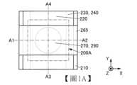
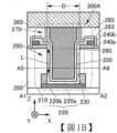
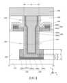
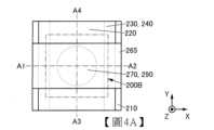
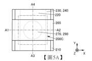
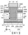
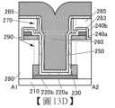
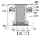
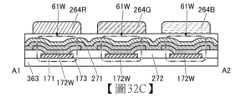
本發明的一個實施方式是一種半導體裝置,包括氧化物半導體層、第一導電層、第二導電層、第三導電層、第一絕緣層、第二絕緣層及第三絕緣層,第一絕緣層位於第一導電層上,第二導電層位於第一絕緣層上,第一導電層具有第一凹部,第一絕緣層及第二導電層在與第一凹部重疊的位置具有第一開口部,氧化物半導體層與第二導電層的頂面、第一凹部的底面及側面接觸且在第一開口部內與第二導電層的側面及第一絕緣層的側面接觸,第二絕緣層在第一開口部內位於氧化物半導體層的內側,第三絕緣層位於第一絕緣層上,在第一絕緣層上覆蓋氧化物半導體層的頂面及側面且在與第一開口部重疊的位置具有第二開口部,並且第三導電層具有在第一開口部內隔著第二絕緣層與氧化物半導體層重疊的部分及位於第二開口部內的部分。One embodiment of the present invention is a semiconductor device, comprising an oxide semiconductor layer, a first conductive layer, a second conductive layer, a third conductive layer, a first insulating layer, a second insulating layer and a third insulating layer, wherein the first insulating layer is located on the first conductive layer, the second conductive layer is located on the first insulating layer, the first conductive layer has a first recess, the first insulating layer and the second conductive layer have a first opening at a position overlapping the first recess, the top surface of the oxide semiconductor layer and the second conductive layer, the bottom surface and the side surface of the first recess are The third insulating layer is in contact with and in contact with the side surface of the second conductive layer and the side surface of the first insulating layer in the first opening, the second insulating layer is located on the inner side of the oxide semiconductor layer in the first opening, the third insulating layer is located on the first insulating layer, covers the top surface and the side surface of the oxide semiconductor layer on the first insulating layer and has a second opening at a position overlapping with the first opening, and the third conductive layer has a portion overlapping with the oxide semiconductor layer through the second insulating layer in the first opening and a portion located in the second opening.
上述半導體裝置較佳為還包括第四絕緣層。較佳的是,第一導電層及第二絕緣層位於第四絕緣層上,從第四絕緣層的頂面到第一導電層的與第一絕緣層接觸的頂面的最短距離比從第四絕緣層的頂面到第二絕緣層的底面的最短距離長。此外,較佳的是,第一導電層及第三導電層位於第四絕緣層上,從第四絕緣層的頂面到第一導電層的與第一絕緣層接觸的頂面的最短距離為從第四絕緣層的頂面到第三導電層的底面的最短距離以上。The semiconductor device preferably further includes a fourth insulating layer. Preferably, the first conductive layer and the second insulating layer are located on the fourth insulating layer, and the shortest distance from the top surface of the fourth insulating layer to the top surface of the first conductive layer in contact with the first insulating layer is longer than the shortest distance from the top surface of the fourth insulating layer to the bottom surface of the second insulating layer. Furthermore, preferably, the first conductive layer and the third conductive layer are located on the fourth insulating layer, and the shortest distance from the top surface of the fourth insulating layer to the top surface of the first conductive layer in contact with the first insulating layer is greater than the shortest distance from the top surface of the fourth insulating layer to the bottom surface of the third conductive layer.
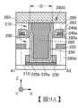
第一導電層較佳為包括第四導電層及第四導電層上的第五導電層。較佳的是,第五導電層具有到達第四導電層的第三開口部,氧化物半導體層與第四導電層的頂面及第五導電層的側面接觸。或者,較佳的是,第五導電層具有第二凹部,第一開口部與第二凹部重疊,氧化物半導體層與第二凹部的底面及側面接觸。The first conductive layer preferably includes a fourth conductive layer and a fifth conductive layer on the fourth conductive layer. Preferably, the fifth conductive layer has a third opening portion reaching the fourth conductive layer, and the oxide semiconductor layer is in contact with the top surface of the fourth conductive layer and the side surface of the fifth conductive layer. Alternatively, preferably, the fifth conductive layer has a second recessed portion, the first opening portion overlaps with the second recessed portion, and the oxide semiconductor layer is in contact with the bottom surface and side surface of the second recessed portion.
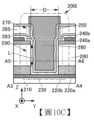
第二導電層較佳為包括第六導電層及第六導電層上的第七導電層。較佳的是,在剖視時第六導電層中的第一開口部的寬度的最大值小於第七導電層中的第一開口部的寬度的最小值,並且氧化物半導體層與第六導電層的頂面及側面、第七導電層的頂面及側面接觸。The second conductive layer preferably includes a sixth conductive layer and a seventh conductive layer on the sixth conductive layer. Preferably, when viewed in cross section, the maximum value of the width of the first opening in the sixth conductive layer is smaller than the minimum value of the width of the first opening in the seventh conductive layer, and the oxide semiconductor layer contacts the top and side surfaces of the sixth conductive layer and the top and side surfaces of the seventh conductive layer.
第三導電層較佳為與第三絕緣層的頂面重疊。The third conductive layer preferably overlaps with the top surface of the third insulating layer.
上述半導體裝置較佳為還包括第八導電層。第八導電層較佳為與第三絕緣層的頂面及第三導電層的頂面接觸。The semiconductor device preferably further includes an eighth conductive layer. The eighth conductive layer preferably contacts the top surface of the third insulating layer and the top surface of the third conductive layer.
第二絕緣層較佳為具有位於第二開口部內的部分。The second insulating layer preferably has a portion located within the second opening.
第三絕緣層較佳為位於第二絕緣層上。The third insulating layer is preferably located on the second insulating layer.
上述半導體裝置較佳為還包括第九導電層。較佳的是,第一絕緣層包括第一層及第一層上的第二層,第九導電層位於第一層上,第二層覆蓋第九導電層的頂面及側面,並且在剖視時氧化物半導體層具有隔著第二層與第九導電層重疊且隔著第二絕緣層與第三導電層重疊的區域。The semiconductor device preferably further includes a ninth conductive layer. Preferably, the first insulating layer includes a first layer and a second layer on the first layer, the ninth conductive layer is located on the first layer, the second layer covers the top and side surfaces of the ninth conductive layer, and the oxide semiconductor layer has a region overlapping the ninth conductive layer via the second layer and overlapping the third conductive layer via the second insulating layer when viewed in cross section.
第一絕緣層較佳為具有與氧化物半導體層接觸的第一區域,並且第一區域較佳為包含鹵素。此外,氧化物半導體層較佳為具有與第一絕緣層接觸的第二區域,並且第二區域較佳為包含鹵素。第一區域及第二區域所包含的鹵素較佳為選自氯、氟、溴和碘中的一種或多種,更佳為氯或氟。The first insulating layer preferably has a first region in contact with the oxide semiconductor layer, and the first region preferably contains a halogen. In addition, the oxide semiconductor layer preferably has a second region in contact with the first insulating layer, and the second region preferably contains a halogen. The halogen contained in the first region and the second region is preferably one or more selected from chlorine, fluorine, bromine and iodine, and more preferably chlorine or fluorine.
較佳的是,氧化物半導體層具有與第一凹部的底面接觸的第三區域及與第二導電層的頂面接觸的第四區域,第三區域及第四區域包含第一元素,第一元素為硼或磷。Preferably, the oxide semiconductor layer has a third region in contact with the bottom surface of the first recess and a fourth region in contact with the top surface of the second conductive layer, and the third region and the fourth region contain a first element, and the first element is boron or phosphorus.
在剖視時第二開口部內的第三導電層的寬度的最大值較佳為第二導電層中的第一開口部的寬度的最小值以下。The maximum value of the width of the third conductive layer in the second opening is preferably equal to or less than the minimum value of the width of the first opening in the second conductive layer when viewed in cross section.
根據本發明的一個實施方式,可以提供一種寄生電容小的電晶體。此外,根據本發明的一個實施方式,可以提供一種電特性良好的電晶體。此外,根據本發明的一個實施方式,可以提供一種通態電流大的電晶體。此外,根據本發明的一個實施方式,可以提供一種能夠實現微型化或高積體化的電晶體、半導體裝置或記憶體裝置。此外,根據本發明的一個實施方式,可以提供一種高清晰或高開口率的顯示裝置。此外,根據本發明的一個實施方式,可以提供一種可靠性高的電晶體、半導體裝置、顯示裝置或記憶體裝置。此外,根據本發明的一個實施方式,可以提供一種功耗低的半導體裝置、顯示裝置或記憶體裝置。此外,根據本發明的一個實施方式,可以提供一種工作速度快的記憶體裝置。此外,根據本發明的一個實施方式,可以提供一種上述電晶體、半導體裝置、顯示裝置或記憶體裝置的製造方法。According to an embodiment of the present invention, a transistor with small parasitic capacitance can be provided. In addition, according to an embodiment of the present invention, a transistor with good electrical characteristics can be provided. In addition, according to an embodiment of the present invention, a transistor with large on-state current can be provided. In addition, according to an embodiment of the present invention, a transistor, a semiconductor device or a memory device capable of miniaturization or high integration can be provided. In addition, according to an embodiment of the present invention, a high-definition or high-aperture display device can be provided. In addition, according to an embodiment of the present invention, a transistor, a semiconductor device, a display device or a memory device with high reliability can be provided. In addition, according to an embodiment of the present invention, a semiconductor device, a display device or a memory device with low power consumption can be provided. In addition, according to an embodiment of the present invention, a memory device with a fast operating speed can be provided. In addition, according to an embodiment of the present invention, a manufacturing method of the above-mentioned transistor, semiconductor device, display device or memory device can be provided.
注意,這些效果的記載不妨礙其他效果的存在。本發明的一個實施方式並不需要具有所有上述效果。此外,可以從說明書、圖式、申請專利範圍的記載衍生上述以外的效果。Note that the description of these effects does not hinder the existence of other effects. An embodiment of the present invention does not need to have all of the above effects. In addition, effects other than the above can be derived from the description of the specification, drawings, and patent application scope.
參照圖式對實施方式進行詳細說明。注意,本發明不侷限於以下說明,而所屬技術領域的通常知識者可以很容易地理解一個事實就是其方式及詳細內容在不脫離本發明的精神及其範圍的情況下可以被變換為各種各樣的形式。因此,本發明不應該被解釋為僅限定在以下所示的實施方式所記載的內容中。The embodiments are described in detail with reference to the drawings. Note that the present invention is not limited to the following description, and a person skilled in the art can easily understand that the methods and details can be transformed into various forms without departing from the spirit and scope of the present invention. Therefore, the present invention should not be interpreted as being limited to the contents described in the embodiments shown below.
注意,在下面說明的發明結構中,在不同的圖式中共同使用相同的符號來表示相同的部分或具有相同功能的部分,而省略反復說明。此外,當表示具有相同功能的部分時有時使用相同的陰影線,而不特別附加符號。Note that in the invention structure described below, the same symbols are used in different drawings to represent the same parts or parts with the same function, and repeated description is omitted. In addition, when representing parts with the same function, the same hatching is sometimes used without special additional symbols.
此外,為了便於理解,有時圖式中示出的各組件的位置、大小及範圍等並不表示其實際的位置、大小及範圍等。因此,所公開的發明並不必然限於圖式中公開的位置、大小及範圍等。In addition, for ease of understanding, the positions, sizes, and ranges of components shown in the drawings sometimes do not represent their actual positions, sizes, and ranges, etc. Therefore, the disclosed invention is not necessarily limited to the positions, sizes, and ranges disclosed in the drawings.
注意,在本說明書等中,為了方便起見,附加了“第一”、“第二”等序數詞,而其並不限制組件的個數或組件的順序(例如,製程順序或疊層順序)。此外,在本說明書中的某一部分對組件附加的序數詞與在本說明書中的其他部分或申請專利範圍對該組件附加的序數詞有時不一致。Note that in this specification, etc., ordinal numbers such as "first" and "second" are added for convenience, and they do not limit the number of components or the order of components (for example, process order or stacking order). In addition, the ordinal numbers added to components in one part of this specification are sometimes inconsistent with the ordinal numbers added to the components in other parts of this specification or the scope of the patent application.
電晶體是半導體元件的一種,並且可以實現放大電流或電壓的功能、控制導通或非導通的切換工作等。本說明書中的電晶體包括IGFET(Insulated Gate Field Effect Transistor:絕緣閘場效電晶體)和薄膜電晶體(TFT:Thin Film Transistor)。A transistor is a type of semiconductor element that can amplify current or voltage, control switching between conduction and non-conduction, etc. Transistors in this specification include IGFET (Insulated Gate Field Effect Transistor) and Thin Film Transistor (TFT).
在本說明書等中,有時將氧化物半導體或金屬氧化物用於半導體層的電晶體及在通道形成區域中包含氧化物半導體或金屬氧化物的電晶體被稱為OS電晶體。此外,有時在通道形成區域中包含矽的電晶體被稱為Si電晶體。In this specification, etc., a transistor using an oxide semiconductor or metal oxide for a semiconductor layer and a transistor containing an oxide semiconductor or metal oxide in a channel forming region are sometimes referred to as an OS transistor. Also, a transistor containing silicon in a channel forming region is sometimes referred to as a Si transistor.
在本說明書等中,電晶體是指至少包括閘極、汲極以及源極這三個端子的元件。電晶體在汲極(汲極端子、汲極區域或汲極電極)與源極(源極端子、源極區域或源極電極)之間具有形成通道的區域(也稱為通道形成區域),並且藉由通道形成區域電流能夠流過源極和汲極之間。注意,在本說明書等中,通道形成區域是指電流主要流過的區域。In this specification, etc., a transistor refers to an element including at least three terminals: a gate, a drain, and a source. The transistor has a region (also called a channel forming region) between the drain (drain terminal, drain region, or drain electrode) and the source (source terminal, source region, or source electrode) that forms a channel, and current can flow between the source and the drain through the channel forming region. Note that in this specification, etc., the channel forming region refers to a region where current mainly flows.
此外,在採用不同極性的電晶體或者電路工作中的電流方向變化的情況等下,源極和汲極的功能有時相互調換。因此,在本說明書中,源極和汲極可以相互調換。In addition, when transistors of different polarities are used or the direction of current changes during circuit operation, the functions of the source and the drain are sometimes interchanged. Therefore, in this specification, the source and the drain can be interchanged.
注意,半導體的雜質例如是指構成半導體的主要成分之外的元素。例如,濃度低於0.1atomic%的元素可以說是雜質。在包含雜質時,例如有時發生半導體的缺陷態密度的增高或者結晶性的降低等。當半導體是氧化物半導體時,作為改變半導體的特性的雜質,例如有第1族元素、第2族元素、第13族元素、第14族元素、第15族元素以及除氧化物半導體的主要成分外的過渡金屬等。明確而言,例如,有氫、鋰、鈉、矽、硼、磷、碳、氮等。此外,有時水也作為雜質起作用。此外,例如有時雜質的混入導致氧化物半導體中的氧空位(還記載為VO)的形成。Note that the impurities of a semiconductor refer to, for example, elements other than the main components that constitute the semiconductor. For example, an element with a concentration of less than 0.1 atomic% can be said to be an impurity. When impurities are contained, for example, the defect state density of the semiconductor may increase or the crystallinity may decrease. When the semiconductor is an oxide semiconductor, the impurities that change the characteristics of the semiconductor include, for example,
注意,在本說明書等中,氧氮化物是指在其組成中含氧量多於含氮量的材料。氮氧化物是指在其組成中含氮量多於含氧量的材料。Note that in this specification and the like, an oxynitride refers to a material containing more oxygen than nitrogen in its composition, and an oxynitride refers to a material containing more nitrogen than oxygen in its composition.
例如可以利用二次離子質譜分析法(SIMS:Secondary Ion Mass Spectrometry)或X射線光電子能譜法(XPS:X-ray Photoelectron Spectroscopy)分析出膜中的氫、氧、碳、氮等元素的含量。在目的元素的含有率高(例如為0.5atomic%以上或1atomic%以上)時,XPS很合適。另一方面,在目的元素的含有率低(例如為0.5atomic%以下或1atomic%以下)時,SIMS很合適。在比較元素含量時,更佳為採用SIMS和XPS的兩者分析技術進行複合分析。For example, the content of hydrogen, oxygen, carbon, nitrogen and other elements in the film can be analyzed by secondary ion mass spectrometry (SIMS) or X-ray photoelectron spectroscopy (XPS). XPS is suitable when the content of the target element is high (for example, 0.5 atomic% or more or 1 atomic% or more). On the other hand, SIMS is suitable when the content of the target element is low (for example, 0.5 atomic% or less or 1 atomic% or less). When comparing the element contents, it is better to use a composite analysis using both SIMS and XPS analysis techniques.
此外,根據情況或狀態,可以互相調換“膜”和“層”。例如,可以將“導電層”變換為“導電膜”。此外,可以將“絕緣膜”變換為“絕緣層”。In addition, depending on the situation or state, "film" and "layer" can be interchanged. For example, "conductive layer" can be replaced with "conductive film". In addition, "insulating film" can be replaced with "insulating layer".
在本說明書等中,“平行”是指兩條直線形成的角度為-10°以上且10°以下的狀態。因此,也包括該角度為-5°以上且5°以下的狀態。”大致平行”是指兩條直線形成的角度為-30°以上且30°以下的狀態。此外,“垂直”是指兩條直線的角度為80°以上且100°以下的狀態。因此,也包括該角度為85°以上且95°以下的狀態。”大致垂直”是指兩條直線形成的角度為60°以上且120°以下的狀態。In this specification, etc., "parallel" refers to a state where the angle formed by two straight lines is greater than -10° and less than 10°. Therefore, it also includes a state where the angle is greater than -5° and less than 5°. "Approximately parallel" refers to a state where the angle formed by two straight lines is greater than -30° and less than 30°. In addition, "perpendicular" refers to a state where the angle formed by two straight lines is greater than 80° and less than 100°. Therefore, it also includes a state where the angle is greater than 85° and less than 95°. "Approximately perpendicular" refers to a state where the angle formed by two straight lines is greater than 60° and less than 120°.
在本說明書等中,“電連接”包括藉由“具有某種電作用的元件”連接的情況。在此,“具有某種電作用的元件”只要可以進行連接對象間的電信號的授收,就對其沒有特別的限制。例如,“具有某種電作用的元件”除了電極或佈線以外還包括電晶體等切換元件、電阻器、線圈、其他具有各種功能的元件等。In this specification, "electrical connection" includes connection through "a component having some kind of electrical function". Here, "a component having some kind of electrical function" is not particularly limited as long as it can transmit and receive electrical signals between the connected objects. For example, "a component having some kind of electrical function" includes switching components such as transistors, resistors, coils, and other components having various functions in addition to electrodes or wiring.
此外,在本說明書等中,在沒有特別的說明的情況下,關態電流(off-state current)是指電晶體處於關閉狀態(也稱為非導通狀態、遮斷狀態)時的源極和汲極之間的洩漏電流。在沒有特別的說明的情況下,在n通道型電晶體中,關閉狀態是指閘極與源極間的電壓Vgs低於臨界電壓Vth(p通道型電晶體中Vgs高於Vth)的狀態。In addition, in this specification, etc., unless otherwise specified, off-state current refers to the leakage current between the source and the drain when the transistor is in the off state (also called non-conducting state, blocked state). Unless otherwise specified, in an n-channel transistor, the off state refers to a state in which the voltageVgs between the gate and the source is lower than the critical voltageVth (in a p-channel transistor,Vgs is higher thanVth ).
在本說明書等中,常開啟是指即使不對閘極施加電壓也存在通道,而電流流過電晶體的狀態。此外,常關閉是指在不對閘極施加電位或者對閘極供應接地電位時電流不流過電晶體的狀態。In this specification, etc., normally open means a state in which a channel exists and current flows through a transistor even when no voltage is applied to the gate. Normally closed means a state in which current does not flow through a transistor when no potential is applied to the gate or when a ground potential is supplied to the gate.
在本說明書等中,錐形形狀是指組件的側面的至少一部分相對於基板面或被形成面傾斜地設置的形狀。例如,較佳為具有傾斜的側面和基板面或被形成面所形成的角度(也被稱為錐形角度)大於0度且小於90度的區域。在此,組件的側面、基板面及被形成面不一定必須完全平坦,也可以是具有微小曲率的近似平面狀或具有微細凹凸的近似平面狀。In this specification, etc., a tapered shape refers to a shape in which at least a portion of the side surface of a component is inclined relative to the substrate surface or the formed surface. For example, it is preferably a region in which the angle formed by the inclined side surface and the substrate surface or the formed surface (also referred to as a tapered angle) is greater than 0 degrees and less than 90 degrees. Here, the side surface, substrate surface, and formed surface of the component do not necessarily have to be completely flat, and may be a nearly flat surface with a slight curvature or a nearly flat surface with slight unevenness.
在本說明書等中,在記載為A位於B上的情況下,A的至少一部分位於B上。因此,例如,可以換稱為A具有位於B上的區域。同樣地,在記載為A與B接觸或者A與B重疊的情況下,A的至少一部分與B接觸或與B重疊。因此,例如可以換稱為A具有與B接觸的區域或者A具有與B重疊的區域。同樣地,在記載為A覆蓋B的情況下,A的至少一部分覆蓋B。因此,例如可以換稱為A具有覆蓋B的區域。In this specification, when it is described that A is located on B, at least a part of A is located on B. Therefore, for example, it can be said that A has a region located on B. Similarly, when it is described that A is in contact with B or A overlaps with B, at least a part of A is in contact with B or overlaps with B. Therefore, for example, it can be said that A has a region in contact with B or A has a region overlapping with B. Similarly, when it is described that A covers B, at least a part of A covers B. Therefore, for example, it can be said that A has a region covering B.
在本說明書等中,有時將使用金屬遮罩或FMM(Fine Metal Mask,高精細金屬遮罩)製造的器件稱為具有MM(Metal Mask)結構的器件。此外,在本說明書等中,有時將不使用金屬遮罩或FMM製造的器件稱為具有MML(Metal Mask Less)結構的器件。In this specification, a device manufactured using a metal mask or FMM (Fine Metal Mask) is sometimes referred to as a device having an MM (Metal Mask) structure. In addition, in this specification, a device manufactured without using a metal mask or FMM is sometimes referred to as a device having an MML (Metal Mask Less) structure.
在本說明書等中,有時將在發光波長不同的發光元件(也稱為發光器件)中分別製造發光層的結構稱為SBS(Side By Side)結構。SBS結構由於可以對各發光元件使材料及結構最佳化,材料及結構的選擇彈性得到提高,可以容易實現亮度及可靠性的提高。In this specification, etc., a structure in which light-emitting layers are separately manufactured in light-emitting elements (also called light-emitting devices) with different light-emitting wavelengths is sometimes referred to as an SBS (Side By Side) structure. The SBS structure can optimize the materials and structures for each light-emitting element, thereby improving the flexibility of material and structure selection, and can easily achieve improved brightness and reliability.
在本說明書等中,有時將電洞或電子表示為“載子”。明確而言,有時將電洞注入層或電子注入層稱為“載子注入層”,將電洞傳輸層或電子傳輸層稱為“載子傳輸層”,將電洞阻擋層或電子阻擋層稱為“載子阻擋層”。注意,有時無法明確地區分上述載子注入層、載子傳輸層及載子阻擋層。此外,有時一個層兼具載子注入層、載子傳輸層和載子阻擋層中的兩者或三者的功能。In this specification, holes or electrons are sometimes referred to as "carriers". To be specific, a hole injection layer or an electron injection layer is sometimes referred to as a "carrier injection layer", a hole transport layer or an electron transport layer is sometimes referred to as a "carrier transport layer", and a hole blocking layer or an electron blocking layer is sometimes referred to as a "carrier blocking layer". Note that the above-mentioned carrier injection layer, carrier transport layer, and carrier blocking layer may not be clearly distinguished. In addition, one layer may have two or three functions of a carrier injection layer, a carrier transport layer, and a carrier blocking layer.
在本說明書等中,發光元件在一對電極間包括EL層。EL層至少包括發光層。在此,作為EL層所包括的層(也被稱為功能層),可以舉出發光層、載子注入層(電洞注入層及電子注入層)、載子傳輸層(電洞傳輸層及電子傳輸層)及載子阻擋層(電洞阻擋層及電子阻擋層)等。在本說明書等中,有時將一對電極中的一方記為像素電極且另一方記為共用電極。In this specification, etc., a light-emitting element includes an EL layer between a pair of electrodes. The EL layer includes at least a light-emitting layer. Here, as layers included in the EL layer (also referred to as functional layers), a light-emitting layer, a carrier injection layer (hole injection layer and electron injection layer), a carrier transport layer (hole transport layer and electron transport layer), and a carrier blocking layer (hole blocking layer and electron blocking layer) can be cited. In this specification, etc., one of a pair of electrodes is sometimes described as a pixel electrode and the other as a common electrode.
在本說明書等中,犧牲層(也可以稱為遮罩層)至少位於發光層(更明確而言是構成EL層的層中被加工為島狀的層)的上方,並且在製程中具有保護該發光層的功能。In this specification and the like, the sacrificial layer (which may also be referred to as a mask layer) is located at least above the light-emitting layer (more specifically, a layer processed into an island shape among the layers constituting the EL layer) and has the function of protecting the light-emitting layer during the manufacturing process.
在本說明書等中,斷開是指層、膜或電極因被形成面的形狀(例如,步階等)而斷開的現象。In this specification and the like, breakage refers to a phenomenon in which a layer, a film, or an electrode is broken due to the shape of the surface on which it is formed (for example, steps, etc.).
注意,有時在本說明書的圖式等中附上表示X方向、Y方向以及Z方向的箭頭。注意,在本說明書等中,“X方向”是指沿著X軸的方向,除了明確指出的情況以外,有時不區別其順向及逆向。“Y方向”及“Z方向”也是同樣的。此外,X方向、Y方向以及Z方向是彼此交叉的方向。例如,X方向、Y方向以及Z方向是彼此正交的方向。Note that arrows indicating the X direction, Y direction, and Z direction are sometimes attached in the drawings and the like of this specification. Note that in this specification and the like, "X direction" refers to the direction along the X axis, and except for the case where it is clearly stated, sometimes the forward direction and the reverse direction are not distinguished. The same applies to "Y direction" and "Z direction". In addition, the X direction, Y direction, and Z direction are directions that intersect each other. For example, the X direction, Y direction, and Z direction are directions that are orthogonal to each other.
(實施方式1) 在本實施方式中,參照圖1A至圖17E說明本發明的一個實施方式的半導體裝置及其製造方法。(Implementation 1)In this implementation, a semiconductor device and a manufacturing method thereof according to an implementation of the present invention are described with reference to FIGS. 1A to 17E .
本發明的一個實施方式的半導體裝置包括氧化物半導體層、第一導電層、第二導電層、第三導電層、第一絕緣層、第二絕緣層及第三絕緣層。A semiconductor device according to an embodiment of the present invention includes an oxide semiconductor layer, a first conductive layer, a second conductive layer, a third conductive layer, a first insulating layer, a second insulating layer, and a third insulating layer.
氧化物半導體層被用作電晶體的半導體層,第一導電層被用作電晶體的源極電極和汲極電極中的一個,第二導電層被用作電晶體的源極電極和汲極電極中的另一個,第三導電層被用作電晶體的閘極電極,並且第二絕緣層被用作電晶體的閘極絕緣層。The oxide semiconductor layer is used as a semiconductor layer of the transistor, the first conductive layer is used as one of a source electrode and a drain electrode of the transistor, the second conductive layer is used as the other of the source electrode and the drain electrode of the transistor, the third conductive layer is used as a gate electrode of the transistor, and the second insulating layer is used as a gate insulating layer of the transistor.
第一絕緣層位於第一導電層上,第二導電層位於第一絕緣層上。第一導電層具有第一凹部,第一絕緣層及第二導電層在與第一凹部重疊的位置具有第一開口部。氧化物半導體層與第二導電層的頂面、第一凹部的底面及側面接觸且在第一開口部內與第二導電層的側面及第一絕緣層的側面接觸。第二絕緣層在第一開口部內位於氧化物半導體層的內側。第三絕緣層位於第一絕緣層上,在第一絕緣層上覆蓋氧化物半導體層的頂面及側面且在與第一開口部重疊的位置具有第二開口部。第三導電層具有在第一開口部內隔著第二絕緣層與氧化物半導體層重疊的部分及位於第二開口部內的部分。The first insulating layer is located on the first conductive layer, and the second conductive layer is located on the first insulating layer. The first conductive layer has a first concave portion, and the first insulating layer and the second conductive layer have a first opening portion at a position overlapping the first concave portion. The oxide semiconductor layer contacts the top surface of the second conductive layer, the bottom surface and the side surface of the first concave portion, and contacts the side surface of the second conductive layer and the side surface of the first insulating layer in the first opening portion. The second insulating layer is located inside the oxide semiconductor layer in the first opening portion. The third insulating layer is located on the first insulating layer, covers the top surface and side surfaces of the oxide semiconductor layer on the first insulating layer and has a second opening at a position overlapping with the first opening. The third conductive layer has a portion overlapping with the oxide semiconductor layer via the second insulating layer in the first opening and a portion located in the second opening.
在本發明的一個實施方式的電晶體中,第一導電層中設置有第一凹部。由此,與不設置第一凹部的情況相比,可以降低第一開口部內的第二絕緣層的底面的高度及第三導電層的底面的高度。在此,各面的高度例如可以以電晶體的被形成面為基準決定。因此,閘極電場容易到達氧化物半導體層,電晶體可以具有良好的電特性。In a transistor of one embodiment of the present invention, a first recess is provided in the first conductive layer. Thus, the height of the bottom surface of the second insulating layer and the height of the bottom surface of the third conductive layer in the first opening can be reduced compared to a case where the first recess is not provided. Here, the height of each surface can be determined based on, for example, the surface on which the transistor is formed. Therefore, the gate electric field can easily reach the oxide semiconductor layer, and the transistor can have good electrical characteristics.
此外,由於在第二導電層與第三導電層重疊的區域中產生寄生電容,所以在該寄生電容較大時電晶體的工作變慢,有時電路的頻率特性下降。In addition, since parasitic capacitance is generated in the region where the second conductive layer and the third conductive layer overlap, the operation of the transistor becomes slower when the parasitic capacitance is larger, and the frequency characteristics of the circuit may be reduced.
於是,本發明的一個實施方式的電晶體較佳為具有減少第二導電層與第三導電層之間的寄生電容的結構。由此,可以實現電晶體的高速工作。此外,可以提供一種具有良好的電特性的半導體裝置。Therefore, the transistor of one embodiment of the present invention preferably has a structure that reduces the parasitic capacitance between the second conductive layer and the third conductive layer. Thus, high-speed operation of the transistor can be achieved. In addition, a semiconductor device with good electrical characteristics can be provided.
第三導電層具有在第一開口部內隔著第二絕緣層與氧化物半導體層重疊的部分及位於第二開口部內的部分。在此情況下,閘極佈線配置在第三絕緣層上,從而可以增加第二導電層和閘極佈線之間的物理距離。因此,可以減少第二導電層與閘極佈線之間的寄生電容。既可將第三導電層的一部分(位於第三絕緣層上的部分)用作閘極佈線,又可在第三絕緣層上設置與第三導電層不同的閘極佈線。The third conductive layer has a portion overlapping the oxide semiconductor layer with the second insulating layer in the first opening and a portion located in the second opening. In this case, the gate wiring is arranged on the third insulating layer, so that the physical distance between the second conductive layer and the gate wiring can be increased. Therefore, the parasitic capacitance between the second conductive layer and the gate wiring can be reduced. A portion of the third conductive layer (the portion located on the third insulating layer) can be used as a gate wiring, and a gate wiring different from the third conductive layer can be arranged on the third insulating layer.
此外,在本發明的一個實施方式的電晶體中,較佳的是,在剖視時第二開口部內的第三導電層的寬度的最大值為第二導電層中的第一開口部的寬度的最小值以下。借助於這種結構,第二導電層與第三導電層之間的寄生電容可以為極小。In addition, in a transistor of an embodiment of the present invention, preferably, when viewed in cross section, the maximum value of the width of the third conductive layer in the second opening is less than the minimum value of the width of the first opening in the second conductive layer. With this structure, the parasitic capacitance between the second conductive layer and the third conductive layer can be extremely small.
在本說明書等中,簡單地記載為“剖視時”,明確而言,有時也可以換稱為“從同一方向剖視時”。例如,在說明多個組件之間的關係的情況下,說明從同一方向剖視時的關係。此時,可以參照一個剖面圖說明該多個組件之間的關係。In this specification, it is sometimes simply described as "when viewed in section", but to be clear, it can also be replaced with "when viewed in section from the same direction". For example, when explaining the relationship between multiple components, the relationship when viewed in section from the same direction is explained. In this case, the relationship between the multiple components can be explained with reference to one cross-sectional view.
此外,也可以設置槽(狹縫)代替開口部。Furthermore, a groove (slit) may be provided instead of the opening.
本發明的一個實施方式的電晶體的源極電極與汲極電極位於不同的高度,因此流過半導體層的電流在高度方向上流過。也就可以說,通道長度方向具有高度方向(垂直方向)的成分,因此本發明的一個實施方式的電晶體也可以被稱為VFET(Vertical Field Effect Transistor:垂直場效應電晶體)、垂直電晶體、垂直通道電晶體等。The source electrode and drain electrode of the transistor of one embodiment of the present invention are located at different heights, so the current flowing through the semiconductor layer flows in the height direction. In other words, the channel length direction has a height direction (vertical direction) component, so the transistor of one embodiment of the present invention can also be called VFET (Vertical Field Effect Transistor), vertical transistor, vertical channel transistor, etc.
本發明的一個實施方式的電晶體的源極電極、半導體層及汲極電極可以重疊設置,由此與將半導體層配置為平面狀的所謂的平面電晶體相比可以大幅度減少佔有面積。In one embodiment of the present invention, the source electrode, semiconductor layer, and drain electrode of the transistor can be overlapped, thereby significantly reducing the occupied area compared to a so-called planar transistor in which the semiconductor layer is arranged in a planar shape.
<半導體裝置的結構例子1> 參照圖1A至圖1D及圖2說明本發明的一個實施方式的半導體裝置的結構。<Structural Example 1 of Semiconductor Device>The structure of a semiconductor device according to one embodiment of the present invention will be described with reference to FIGS. 1A to 1D and 2.
[電晶體200A] 圖1A是包括電晶體200A的半導體裝置的平面圖。圖1B及圖2都是沿著圖1A所示的點劃線A1-A2的剖面圖。圖2相當於圖1B的放大圖的一個例子,更詳細地示出各層的結構例子。圖1C是沿著圖1A所示的點劃線A3-A4的剖面圖。圖1D是沿著圖1B及圖1C所示的點劃線A5-A6的剖面圖。圖1D也可以說是包括絕緣層280的XY平面的剖面圖。在圖1A的平面圖中,為了明確起見,省略部分組件。有時在後面的平面圖中也省略部分組件。[
圖1A至圖1D及圖2所示的半導體裝置包括基板(未圖示)上的絕緣層210、絕緣層210上的電晶體200A、絕緣層210上的絕緣層280、電晶體200A上的絕緣層283、絕緣層283上的絕緣層285及絕緣層285上的導電層265。絕緣層210、絕緣層280、絕緣層283及絕緣層285被用作層間膜。The semiconductor device shown in FIGS. 1A to 1D and 2 includes an insulating
電晶體200A包括導電層220a、導電層220a上的導電層220b、絕緣層280上的導電層240a、導電層240a上的導電層240b、氧化物半導體層230、氧化物半導體層230上的絕緣層250及絕緣層250上的導電層260。The
以下有時將導電層220a及導電層220b統稱為導電層220。此外,有時將導電層240a及導電層240b統稱為導電層240。In the following, the
在電晶體200A中,氧化物半導體層230被用作半導體層,導電層260被用作閘極電極,絕緣層250被用作閘極絕緣層,導電層220被用作源極電極和汲極電極中的一個,導電層240被用作源極電極和汲極電極中的另一個。此外,導電層265被用作閘極佈線。In
氧化物半導體層230的與絕緣層280接觸的區域中的至少一部分被用作電晶體200A的通道形成區域。氧化物半導體層230的與導電層220接觸的區域及氧化物半導體層230的與導電層240接觸的區域中的一個被用作源極區域,另一個被用作汲極區域。也就是說,通道形成區域夾在源極區域和汲極區域之間。At least a portion of the region of the
如圖1B及圖1C所示,導電層220b、絕緣層280、導電層240a及導電層240b中設置有到達導電層220a的開口部290。在此,開口部290的底部包括導電層220a的頂面,開口部290的側壁包括導電層220b的側面、絕緣層280的側面、導電層240a的側面及導電層240b的側面。開口部290包括導電層220b所包括的開口部、絕緣層280所包括的開口部、導電層240a所包括的開口部以及導電層240b所包括的開口部。換言之,絕緣層280與導電層220a重疊的區域中的開口部是開口部290的一部分,導電層220b與導電層220a重疊的區域中的開口部是開口部290的另一部分,導電層240a與導電層220a重疊的區域中的開口部是開口部290的另一部分,並且導電層240b與導電層220a重疊的區域中的開口部是開口部290的另一部分。此外,在俯視時各層的開口部290的形狀及大小也可以不同。此外,當開口部290的頂面形狀為圓形時,各層中的開口部既可以是同心圓狀,也可以不是同心圓狀。As shown in FIG1B and FIG1C, the
電晶體200A的組件的至少一部分配置在開口部290內。明確而言,氧化物半導體層230、絕緣層250及導電層260都以其至少一部分位於開口部290內的方式配置。氧化物半導體層230在開口部290內與導電層220a的頂面、導電層220b的側面、絕緣層280的側面、導電層240a的頂面及側面以及導電層240b的側面接觸。絕緣層250在開口部290內位於氧化物半導體層230的內側,導電層260在開口部290內位於絕緣層250的內側。At least a portion of the components of the
此外,氧化物半導體層230及絕緣層250的配置在開口部290內的部分反映了開口部290的形狀。明確而言,以覆蓋開口部290的底部及側壁的方式設置氧化物半導體層230,以覆蓋氧化物半導體層230的方式設置絕緣層250。此外,以嵌入反映了開口部290的形狀的絕緣層250的凹部的至少一部分的方式設置導電層260。In addition, the portions of the
電晶體200A所包括的導電層220包括導電層220a及導電層220a上的導電層220b,在導電層220b中設置有開口部290。換言之,導電層220具有凹部,該凹部的底面相當於導電層220a的頂面,該凹部的側面相當於導電層220b的開口部290一側的側面。The
藉由使導電層220b包括開口部290,與不包括開口部290的情況相比,可以使開口部290內的絕緣層250的底面的高度及導電層260的底面的高度都低於導電層220b的與絕緣層280接觸的頂面的高度。在此,各面的高度可以以電晶體的被形成面為基準決定。在此,可以以絕緣層210的頂面為基準。用於基準的面不侷限於電晶體的被形成面。例如,也可以以設置有電晶體或半導體裝置的基板的頂面為基準。By making the
如圖2所示,從絕緣層210的頂面到導電層220b的與絕緣層280接觸的頂面的最短距離Tc較佳為比從絕緣層210的頂面到絕緣層250的底面的最短距離Ta長。由此,可以增大導電層220b的側面與氧化物半導體層230的接觸面積,從而可以降低導電層220b與氧化物半導體層230的接觸電阻。因此,可以抑制起因於導電層220b與氧化物半導體層230的接觸電阻的電晶體200A的通態電流的降低。最短距離Ta可以根據開口部290內的絕緣層250的底面決定。As shown in FIG2 , the shortest distance Tc from the top surface of the insulating
此外,如圖2所示,最短距離Tc更佳為從絕緣層210的頂面到導電層260的底面的最短距離Tb以上,進一步較佳為比最短距離Tb長。由此,閘極電場容易到達氧化物半導體層230的通道形成區域,從而可以提高電晶體200A的電特性。再者,閘極電場還容易到達氧化物半導體層230的與導電層220b接觸的區域,因此可以增大電晶體200A的通態電流。此外,無論將導電層220還是導電層240用作汲極電極,都可以提高電晶體200A的電特性。最短距離Tb可以根據開口部290內的導電層260的底面決定。In addition, as shown in FIG2 , the shortest distance Tc is preferably greater than the shortest distance Tb from the top surface of the insulating
作為導電層220b,較佳為使用包含氧的導電材料。由此,可以降低氧化物半導體層230與導電層220b的接觸電阻。同樣地,作為導電層240a,較佳為使用包含氧的導電材料。由此,可以降低氧化物半導體層230與導電層240a的接觸電阻。在導電層220及導電層240具有疊層結構的情況下,將包含氧的導電材料用於該疊層結構中的離通道形成區域最近的層來降低與氧化物半導體層230的接觸電阻,可以縮短源極與汲極之間的電流路徑來增大電晶體的通態電流。作為包含氧的導電材料,較佳為使用具有導電性的金屬氧化物(也稱為氧化物導電體)。As the
此外,在氧化物半導體層230與導電層240a的頂面及側面接觸的情況下,與只接觸於導電層240a的側面的情況相比,氧化物半導體層230與導電層240a的接觸面積增大,可以進一步降低氧化物半導體層230與導電層240a的接觸電阻。因此,可以抑制起因於接觸電阻的電晶體200A的通態電流的降低。Furthermore, when the
如圖1B及圖1C所示,絕緣層283覆蓋氧化物半導體層230的頂面及側面、導電層240a及導電層240b的各側面。絕緣層283在與開口部290重疊的位置具有到達氧化物半導體層230的開口部270。電晶體200A的組件的至少一部分配置在開口部270內。明確而言,絕緣層250及導電層260都以其至少一部分位於開口部270內的方式配置。絕緣層250在開口部270內與氧化物半導體層230及絕緣層283接觸。As shown in FIG. 1B and FIG. 1C , the insulating
絕緣層250的配置在開口部270內的部分反映了開口部270的形狀。明確而言,以覆蓋開口部270的側壁(絕緣層283的側面)的方式設置絕緣層250。此外,以嵌入反映了開口部270的形狀的絕緣層250的凹部的至少一部分的方式設置導電層260。The portion of the insulating
在電晶體200A中,因為導電層260不與導電層240的頂面重疊,所以可以減少導電層240與導電層260之間的寄生電容。如圖1B及圖1C所示,在剖視時導電層260的寬度的最大值小於開口部290的寬度D。如此,當導電層260的寬度的最大值小於開口部290的寬度D時,可以減少導電層260與導電層240之間的寄生電容,所以是較佳的。此外,例如,如圖1B或圖1C所示,本發明的一個實施方式的半導體裝置中的兩個寬度的大小關係可以根據平行於Z方向的一個剖面確認。In the
注意,開口部290的寬度D有時在深度方向上發生變化。在此,尤其是作為寬度D,使用剖視時的導電層240的開口部290一側的兩個側面之間的最短距離。換言之,作為開口部290的寬度D,使用導電層240中的開口部290的寬度的最小值。在圖1B及圖1C中,開口部290的寬度D為導電層240a中的開口部290的寬度的最小值。Note that the width D of the
圖1B及圖1C示出開口部270的寬度與開口部290的寬度一致(與寬度D相等)的例子。開口部270的寬度較佳為不超過開口部290的寬度D與氧化物半導體層230的厚度的2倍之和。此外,在將絕緣層250設置在開口部270的內部的情況下,開口部270的寬度較佳為不超過開口部290的寬度D與絕緣層250的厚度的2倍之和。此外,開口部270的寬度更佳為等於或小於開口部290的寬度。由此,導電層260與導電層240的頂面不重疊,可以減少導電層260與導電層240之間的寄生電容,所以是較佳的。雖然在本實施方式中主要示出導電層260與導電層240的頂面不重疊的例子,但是導電層260也可以具有與導電層240的頂面重疊的部分。該重疊的部分越小,越可以減少導電層260與導電層240之間的寄生電容,所以是較佳的。此外,開口部270的寬度較佳為大於從開口部290的寬度D減去氧化物半導體層230的厚度的2倍而得的長度。由此,可以防止絕緣層283及絕緣層285位於開口部290的內部。1B and 1C show an example in which the width of the
注意,開口部270的寬度有時在深度方向上發生變化。在此,尤其是作為開口部270的寬度,使用剖視時的設置在絕緣層283中的開口部270的寬度的最大值。Note that the width of the
導電層260的頂面的高度與絕緣層285的頂面的高度較佳為一致或大致一致。導電層265設置在絕緣層285上、絕緣層283上及導電層260上,並與導電層260的頂面接觸。導電層260與導電層265也可以說是彼此電連接。絕緣層283及絕緣層285位於導電層265與導電層240之間。由此,可以增加導電層265與導電層240之間的物理距離,可以減少導電層265與導電層240之間的寄生電容。The height of the top surface of the
也就是說,電晶體200A具有降低源極電極和汲極電極中的另一個與閘極電極之間的寄生電容及源極電極和汲極電極中的另一個與閘極佈線之間的寄生電容的結構。因此,可以提高電路的頻率特性。That is, the
圖1B示出在開口部290的外側導電層240a的端部、導電層240b的端部及氧化物半導體層230的端部對齊的結構。像後面說明的製造方法例子那樣,導電層240a、導電層240b及氧化物半導體層230可以藉由使用相同的遮罩進行加工來製造。因此,可以減少半導體裝置的製造所需要的遮罩個數,所以是較佳的。注意,本發明不侷限於此。例如,在X方向或Y方向上,氧化物半導體層230的端部、導電層240a的端部及導電層240b的端部中的任一個也可以位於其他的內側或外側。FIG1B shows a structure in which the end of the
導電層240在與導電層220重疊的區域中具有開口部290。此外,導電層240較佳為不設置在絕緣層280所包括的開口部290內部。也就是說,導電層240較佳為不具有與開口部290內的絕緣層280的側面接觸的區域。藉由採用這種結構,可以在導電層240及絕緣層280中一次形成開口部290。此外,當開口部290內的導電層240的側面與開口部290內的絕緣層280的側面對齊時,可以使設置在開口部290內部的氧化物半導體層230的厚度分佈均勻。此外,可以抑制氧化物半導體層230因導電層240與絕緣層280的步階而分離。The
雖然在圖1B及圖1C中示出開口部290內的導電層240a的側面與開口部290內的絕緣層280的側面齊平(也可以說對齊,大致對齊)的結構,但是本發明不侷限於此。例如,開口部290內的導電層240(導電層240a和導電層240b中的一者或兩者)的側面與開口部290內的絕緣層280的側面也可以不連續。此外,開口部290中的導電層240的側面的傾斜度與開口部290中的絕緣層280的側面的傾斜度也可以彼此不同。此時,例如,開口部290內的導電層240的側面的錐形角度較佳為小於開口部290內的絕緣層280的側面的錐形角度。藉由採用這種結構,氧化物半導體層230對開口部290內的導電層240的側面的覆蓋性得到提高,從而可以減少空洞等缺陷。此外,在絕緣層280具有疊層結構的情況下,開口部290內的各層的側面的傾斜度也可以不同。同樣地,在導電層240具有疊層結構的情況下,開口部290內的各層的側面的傾斜度也可以不同。Although FIG. 1B and FIG. 1C show a structure in which the side surface of the
電晶體200A較佳為在包含通道形成區域的氧化物半導體層230中含有用作半導體的金屬氧化物(以下,也稱為氧化物半導體)。也就可以說,電晶體200A為OS電晶體。The
在OS電晶體中,當氧化物半導體的通道形成區域中存在氧空位(VO)及雜質時,電特性容易變動而可能使可靠性下降。此外,氧空位附近的氫形成氫進入氧空位中的缺陷(以下有時稱為VOH)而可能會產生成為載子的電子。因此,當在氧化物半導體的通道形成區域中包含氧空位時,OS電晶體會具有常開啟特性。由此,在氧化物半導體的通道形成區域中,較佳為儘量減少氧空位及雜質。換言之,較佳的是,氧化物半導體中的通道形成區域的載子濃度降低且被i型化(本質化)或實質上被i型化。In an OS transistor, when oxygen vacancies (VO ) and impurities are present in the channel forming region of an oxide semiconductor, the electrical characteristics are easily changed and reliability may be reduced. In addition, hydrogen near the oxygen vacancy forms a defect in which hydrogen enters the oxygen vacancy (hereinafter sometimes referred to as VOH ) and may generate electrons that become carriers. Therefore, when oxygen vacancies are included in the channel forming region of an oxide semiconductor, the OS transistor has a normally-on characteristic. Therefore, in the channel forming region of an oxide semiconductor, it is preferred to minimize oxygen vacancies and impurities. In other words, it is preferred that the carrier concentration of the channel forming region in the oxide semiconductor is reduced and is i-typed (intrinsically) or substantially i-typed.
另一方面,OS電晶體的源極區域及汲極區域較佳為如下區域:由於與通道形成區域相比氧空位多、VOH多或者氫、氮、金屬元素等雜質濃度高而載子濃度增加,由此被低電阻化。也就是說,與通道形成區域相比,OS電晶體的源極區域及汲極區域較佳為載子濃度更高且電阻更低的n型區域。On the other hand, the source region and drain region of the OS transistor are preferably the following regions: compared with the channel formation region, the source region and drain region of the OS transistor are preferably n-type regions with higher carrier concentration and lower resistance due to the higher oxygen vacancies, moreVOH , or higher concentration of impurities such as hydrogen, nitrogen, and metal elements.
如上所述,氧化物半導體層230設置在絕緣層280所具有的開口部290的內部。此外,在電晶體200A中,源極電極和汲極電極中的一個(這裡為導電層220)位於下方,源極電極和汲極電極中的另一個(這裡為導電層240)位於上方,因此電流在上下方向上流過。也就是說,沿絕緣層280所具有的開口部290的側面形成通道。As described above, the
氧化物半導體層230在開口部290內與導電層220a的頂面、導電層220b的側面、導電層240a的頂面及側面以及導電層240b的側面接觸。氧化物半導體層230還與導電層240b的頂面的一部分接觸。如此,藉由使氧化物半導體層230不僅接觸於導電層240a的側面及導電層240b的側面還接觸於導電層240a的頂面及導電層240b的頂面,可以增大氧化物半導體層230與導電層240接觸的面積。因此,可以降低氧化物半導體層230與導電層240之間的接觸電阻。The
如圖1D所示,絕緣層280接觸於氧化物半導體層230的外周整體。因此,電晶體200A的通道形成區域有可能形成在開口部290內的氧化物半導體層230的週邊整體(與絕緣層280接觸的區域整體)。此外,圖1D也可以說是包括氧化物半導體層230的通道形成區域的XY平面的剖面圖。As shown in FIG1D , the insulating
電晶體200A的通道長度為源極區域與汲極區域之間的距離。換言之,可以說電晶體200A的通道長度根據導電層220上的絕緣層280的厚度決定。在圖1B及圖1C中,以虛線的雙箭頭表示電晶體200A的通道長度L。在此,示出通道長度L相當於絕緣層280的開口部290一側的側面的長度的例子。The channel length of the
在平面型電晶體中,通道長度根據光微影法的曝光極限設定,但是在本發明的一個實施方式中可以根據絕緣層280的厚度設定通道長度。因此,可以將電晶體200A的通道長度設定為光微影法的曝光極限以下的非常微細的結構(例如60nm以下、50nm以下、40nm以下、30nm以下、20nm以下或10nm以下且0.1nm以上、1nm以上或5nm以上)。因此,電晶體200A的通態電流變大,從而可以提高頻率特性。In a planar transistor, the channel length is set according to the exposure limit of the photolithography method, but in one embodiment of the present invention, the channel length can be set according to the thickness of the insulating
再者,如上所述,可以在開口部290內形成通道形成區域、源極區域及汲極區域。因此,與在XY平面上分別設置通道形成區域、源極區域及汲極區域的平面型電晶體相比,可以減小電晶體200A的佔有面積。由此,可以實現半導體裝置的高積體化。此外,在將本發明的一個實施方式的半導體裝置用於記憶體裝置時,可以增大單位面積的記憶容量。Furthermore, as described above, a channel forming region, a source region, and a drain region can be formed in the
此外,如圖1D所示,氧化物半導體層230、絕緣層250及導電層260設置為同心圓狀。因此,設置在中心的導電層260的側面隔著絕緣層250與氧化物半導體層230的側面相對。換言之,在俯視時氧化物半導體層230的外周整體成為通道形成區域。此時,例如,根據氧化物半導體層230的外周的長度決定電晶體200A的通道寬度。也就可以說,根據開口部290的寬度(在開口部290的俯視時的形狀為圓形的情況下,徑)的大小決定電晶體200A的通道寬度。在圖1B至圖1D中,以雙點劃線的雙箭頭表示開口部290的寬度D。在圖1D中,以點劃線的雙箭頭表示電晶體200A的通道寬度W。藉由增大開口部290的寬度D,可以增大單位面積的通道寬度而增大通態電流。In addition, as shown in FIG. 1D , the
在利用光微影法形成開口部290時,根據光微影法的曝光極限設定開口部290的寬度D。此外,開口部290的寬度D根據設置在開口部290中的氧化物半導體層230、絕緣層250及導電層260各自的厚度而設定。開口部290的寬度D例如較佳為5nm以上、10nm以上或20nm以上且100nm以下、60nm以下、50nm以下、40nm以下或30nm以下。注意,當在俯視時開口部290為圓形的情況下,開口部290的寬度D相當於開口部290的直徑,通道寬度W可以算出為“D×π”。When the
此外,電晶體200A的通道長度L較佳為至少比電晶體200A的通道寬度W小。電晶體200A的通道長度L較佳為電晶體200A的通道寬度W的0.1倍以上且0.99倍以下,更佳為0.5倍以上且0.8倍以下。藉由採用這種結構,可以實現具有良好的電特性及高可靠性的電晶體。In addition, the channel length L of the
此外,藉由以在俯視時具有圓形形狀的方式形成開口部290,氧化物半導體層230、絕緣層250及導電層260以同心圓狀設置。由此,導電層260與氧化物半導體層230間的距離大致均勻,所以可以對氧化物半導體層230大致均勻地施加閘極電場。In addition, by forming the
雖然在本實施方式中示出開口部290及開口部270在俯視時的形狀為圓形的例子,但是本發明不侷限於此。開口部290及開口部270在俯視時的形狀例如可以為圓形、橢圓形等近似圓形、三角形、四角形(包括長方形、菱形、正方形)、五角形、星形多邊形等多邊形或者這些多邊形的角部呈圓形的形狀。多邊形也可以是凹多邊形(至少一個內角超過180度的多邊形)或凸多邊形(內角都是180度以下的多邊形)。如圖1A等所示,開口部290及開口部270在俯視時的形狀較佳為圓形。藉由為圓形,可以提高形成開口部時的加工精度,可以形成微細的開口部。在本說明書等中,圓形不侷限於正圓。Although the example in which the
<半導體裝置的構成材料> 以下說明可用於本實施方式的半導體裝置的材料。構成本實施方式的半導體裝置的各層既可具有單層結構又可具有疊層結構。圖1B及圖1C示出導電層220a、氧化物半導體層230及導電層260具有單層結構的例子。此外,圖2示出導電層220a、氧化物半導體層230及導電層260具有疊層結構的例子。<Materials constituting semiconductor devices>The following describes materials that can be used for the semiconductor device of this embodiment. Each layer constituting the semiconductor device of this embodiment may have a single layer structure or a stacked layer structure. FIG. 1B and FIG. 1C show an example in which the
[氧化物半導體層230] 如上所述,氧化物半導體層230具有通道形成區域。該通道形成區域是i型(本質)或實質上i型。氧化物半導體層230還具有源極區域及汲極區域。該源極區域及該汲極區域是與通道形成區域相比載子濃度高的n型區域(低電阻區域)。[Oxide semiconductor layer 230]As described above, the
對用於氧化物半導體層230的半導體材料的結晶性沒有特別的限制,可以使用非晶半導體、單晶半導體或具有單晶以外的結晶性的半導體(微晶半導體、多晶半導體或其一部分具有結晶區域的半導體)。當使用單晶半導體或具有結晶性的半導體時可以抑制電晶體的特性劣化,所以是較佳的。There is no particular limitation on the crystallinity of the semiconductor material used for the
被用作半導體的金屬氧化物的能帶間隙較佳為2.0eV以上,更佳為2.5eV以上。藉由使用能帶間隙較寬的金屬氧化物,可以減小電晶體的關態電流。OS電晶體的關態電流小,所以可以充分降低半導體裝置的功耗。此外,OS電晶體的頻率特性高,所以可以使半導體裝置高速工作。The band gap of the metal oxide used as a semiconductor is preferably 2.0 eV or more, and more preferably 2.5 eV or more. By using a metal oxide with a wider band gap, the off-state current of the transistor can be reduced. The off-state current of the OS transistor is small, so the power consumption of the semiconductor device can be sufficiently reduced. In addition, the frequency characteristics of the OS transistor are high, so the semiconductor device can be operated at high speed.
作為可用於氧化物半導體層230的金屬氧化物,例如,可以舉出銦氧化物、鎵氧化物及鋅氧化物。金屬氧化物較佳為至少包含銦(In)或鋅(Zn)。此外,金屬氧化物較佳為包含選自銦、元素M和鋅中的兩個或三個。注意,元素M為與氧的鍵合能量高的金屬元素或半金屬元素,例如為與氧的鍵合能量比銦高的金屬元素或半金屬元素。明確而言,作為元素M,可以舉出鋁、鎵、錫、釔、鈦、釩、鉻、錳、鐵、鈷、鎳、鋯、鉬、鉿、鉭、鎢、鑭、鈰、釹、鎂、鈣、鍶、鋇、硼、矽、鍺及銻等。金屬氧化物所包含的元素M較佳為上述元素中的任一種或多種,更佳為選自鋁、鎵、錫和釔中的一種或多種,進一步較佳為鎵。注意,在本說明書等中,有時將金屬元素和半金屬元素統稱為“金屬元素”,本說明書等中記載的“金屬元素”有時包括半金屬元素。As metal oxides that can be used for the
氧化物半導體層230例如可以使用銦氧化物(In氧化物)、銦鋅氧化物(In-Zn氧化物,也記為IZO(註冊商標))、銦錫氧化物(In-Sn氧化物)、銦鈦氧化物(In-Ti氧化物)、銦鎵氧化物(In-Ga氧化物)、銦鎵鋁氧化物(In-Ga-Al氧化物)、銦鎵錫氧化物(In-Ga-Sn氧化物,也記為IGTO)、鎵鋅氧化物(Ga-Zn氧化物,也記為GZO)、鋁鋅氧化物(Al-Zn氧化物,也記為AZO)、銦鋁鋅氧化物(In-Al-Zn氧化物,也記為IAZO)、銦錫鋅氧化物(In-Sn-Zn氧化物,也記為ITZO(註冊商標))、銦鈦鋅氧化物(In-Ti-Zn氧化物)、銦鎵鋅氧化物(In-Ga-Zn氧化物,也記為IGZO)、銦鎵錫鋅氧化物(In-Ga-Sn-Zn氧化物,也記為IGZTO)、銦鎵鋁鋅氧化物(In-Ga-Al-Zn氧化物,也記為IGAZO、IGZAO或IAGZO)等。或者,可以使用包含矽的銦錫氧化物、鎵錫氧化物(Ga-Sn氧化物)、鋁錫氧化物(Al-Sn氧化物)等。The oxide semiconductor layer 230 may be made of, for example, indium oxide (In oxide), indium zinc oxide (In-Zn oxide, also referred to as IZO (registered trademark)), indium tin oxide (In-Sn oxide), indium titanium oxide (In-Ti oxide), indium gallium oxide (In-Ga oxide), indium gallium aluminum oxide (In-Ga-Al oxide), indium gallium tin oxide (In-Ga-Sn oxide, also referred to as IGTO), gallium zinc oxide (Ga-Zn oxide, also referred to as GZO), aluminum zinc oxide (Al-Zn oxide, also referred to as Indium-tin-zinc oxide (IGZO), indium-aluminum-zinc oxide (In-Al-Zn oxide, also referred to as IAZO), indium-tin-zinc oxide (In-Sn-Zn oxide, also referred to as ITZO (registered trademark)), indium-titanium-zinc oxide (In-Ti-Zn oxide), indium-gallium-zinc oxide (In-Ga-Zn oxide, also referred to as IGZO), indium-gallium-tin-zinc oxide (In-Ga-Sn-Zn oxide, also referred to as IGZTO), indium-gallium-aluminum-zinc oxide (In-Ga-Al-Zn oxide, also referred to as IGAZO, IGZAO or IAGZO), etc. Alternatively, indium-tin oxide, gallium-tin oxide (Ga-Sn oxide), aluminum-tin oxide (Al-Sn oxide) or the like containing silicon may be used.
藉由提高相對於金屬氧化物中的所有金屬元素的原子個數的總和的銦的原子個數之比,可以提高電晶體的場效移動率。此外,可以實現通態電流大的電晶體。By increasing the ratio of the number of indium atoms to the total number of atoms of all metal elements in the metal oxide, the field-effect mobility of the transistor can be increased. In addition, a transistor with a large on-state current can be realized.
注意,金屬氧化物也可以代替銦或除了銦以外還包含一種或多種元素週期表中的週期數大的金屬元素。有如下傾向:金屬元素的軌域重疊越大,金屬氧化物中的載子傳導越大。因此,藉由包含週期數大的金屬元素,有時可以提高電晶體的場效移動率。作為週期數大的金屬元素,可以舉出屬於第5週期的金屬元素以及屬於第6週期的金屬元素等。作為該金屬元素,明確而言,可以舉出釔、鋯、銀、鎘、錫、銻、鋇、鉛、鉍、鑭、鈰、鐠、釹、鉕、釤及銪等。注意,鑭、鈰、鐠、釹、鉕、釤及銪被稱為輕稀土元素。Note that the metal oxide may also replace indium or contain one or more metal elements with a large period number in the element period table in addition to indium. There is a tendency that the greater the orbital overlap of the metal element, the greater the carrier conduction in the metal oxide. Therefore, by including a metal element with a large period number, the field-effect mobility of the transistor can sometimes be improved. As metal elements with a large period number, metal elements belonging to the 5th period and metal elements belonging to the 6th period can be cited. As the metal element, specifically, yttrium, zirconium, silver, cadmium, tin, antimony, barium, lead, bismuth, ruthenium, arsenic, neodymium, bismuth, samarium and methanium can be cited. Note that ruthenium, arsenic, neodymium, bismuth, protium, and mercury are called light rare earth elements.
此外,金屬氧化物也可以包含一種或多種非金屬元素。在金屬氧化物包含非金屬元素時,有時載子濃度增加或者能帶間隙變窄等而可以提高電晶體的場效移動率。作為非金屬元素,例如可以舉出碳、氮、磷、硫、硒、溴及氫等。In addition, the metal oxide may also contain one or more non-metallic elements. When the metal oxide contains non-metallic elements, the field-effect mobility of the transistor may be improved by increasing the carrier concentration or narrowing the energy band gap. Examples of non-metallic elements include carbon, nitrogen, phosphorus, sulfur, selenium, bromine, and hydrogen.
此外,藉由提高相對於金屬氧化物中的所有金屬元素的原子個數的總和的鋅的原子個數之比,金屬氧化物的結晶性提高,由此可以抑制金屬氧化物中的雜質的擴散。因此,電晶體的電特性變動被抑制,由此可以提高可靠性。In addition, by increasing the ratio of the number of zinc atoms to the total number of atoms of all metal elements in the metal oxide, the crystallinity of the metal oxide is improved, thereby suppressing the diffusion of impurities in the metal oxide. Therefore, the change of the electrical characteristics of the transistor is suppressed, thereby improving the reliability.
此外,藉由提高相對於金屬氧化物中的所有金屬元素的原子個數的總和的元素M的原子個數之比,可以得到能帶間隙較寬的金屬氧化物。此外,可以抑制在金屬氧化物中形成氧空位。因此,起因於氧空位的載子生成得到抑制,由此可以實現關態電流小的電晶體。此外,可以抑制電晶體的臨界電壓的漂移。此外,電晶體的電特性的變動得到抑制,從而可以提高可靠性。In addition, by increasing the ratio of the number of atoms of element M to the total number of atoms of all metal elements in the metal oxide, a metal oxide with a wider band gap can be obtained. In addition, the formation of oxygen vacancies in the metal oxide can be suppressed. Therefore, the generation of carriers due to oxygen vacancies is suppressed, thereby realizing a transistor with a small off-state current. In addition, the drift of the critical voltage of the transistor can be suppressed. In addition, the variation of the electrical characteristics of the transistor is suppressed, thereby improving the reliability.
根據用於氧化物半導體層230的金屬氧化物的組成而電晶體的電特性及可靠性不同。因此,藉由對應於電晶體所需的電特性及可靠性使金屬氧化物的組成不同,可以實現兼具優異的電特性及高可靠性的半導體裝置。The electrical characteristics and reliability of the transistor vary depending on the composition of the metal oxide used for the
在金屬氧化物為In-M-Zn氧化物時,該In-M-Zn氧化物中的In的原子個數比較佳為元素M的原子個數比以上。作為這種In-M-Zn氧化物的金屬元素的原子個數比,例如可以舉出In:M:Zn=1:1:0.5、In:M:Zn=1:1:1、In:M:Zn=1:1:1.2、In:M:Zn=1:1:2、In:M:Zn=2:1:3、In:M:Zn=3:1:1、In:M:Zn=3:1:2、In:M:Zn=4:2:3、In:M:Zn=4:2:4.1、In:M:Zn=5:1:3、In:M:Zn=5:1:6、In:M:Zn=5:1:7、In:M:Zn=5:1:8、In:M:Zn=6:1:6、In:M:Zn=5:2:5以及它們附近的組成等。此外,附近的組成包括所希望的原子個數比的±30%的範圍。藉由增大金屬氧化物中的銦的原子個數比,可以提高電晶體的通態電流或場效移動率等。When the metal oxide is In-M-Zn oxide, the number of In atoms in the In-M-Zn oxide is preferably greater than or equal to the number of atoms of element M. Examples of the atomic number ratio of metal elements in such In-M-Zn oxides include In:M:Zn=1:1:0.5, In:M:Zn=1:1:1, In:M:Zn=1:1:1.2, In:M:Zn=1:1:2, In:M:Zn=2:1:3, In:M:Zn=3:1:1, In:M:Zn=3:1:2, In:M:Zn=4:2:3, In:M:Zn=4:2:4.1, In:M:Zn=5:1:3, In:M:Zn=5:1:6, In:M:Zn=5:1:7, In:M:Zn=5:1:8, In:M:Zn=6:1:6, In:M:Zn=5:2:5 and compositions nearby. In addition, the composition of the vicinity includes a range of ±30% of the desired atomic number ratio. By increasing the atomic number ratio of indium in the metal oxide, the on-state current or field effect mobility of the transistor can be improved.
In-M-Zn氧化物中的In的原子個數比也可以小於元素M的原子個數比。作為這種In-M-Zn氧化物的金屬元素的原子個數比,例如可以舉出In:M:Zn=1:3:2、In:M:Zn=1:3:3、In:M:Zn=1:3:4以及它們附近的組成。藉由增高金屬氧化物中的M的原子個數的比例,可以抑制氧空位的生成。The atomic number ratio of In in the In-M-Zn oxide may be smaller than the atomic number ratio of the element M. Examples of atomic number ratios of metal elements in such In-M-Zn oxides include In:M:Zn=1:3:2, In:M:Zn=1:3:3, In:M:Zn=1:3:4, and compositions close thereto. By increasing the atomic number ratio of M in the metal oxide, the generation of oxygen vacancies can be suppressed.
注意,在作為元素M包含多個金屬元素時,該金屬元素的原子個數的比例的總計可以為元素M的原子個數的比例。Note that when a plurality of metal elements are included as the element M, the total ratio of the number of atoms of the metal elements can be the ratio of the number of atoms of the element M.
在本說明書等中,相對於含有的所有金屬元素的原子個數的總和的銦的原子個數之比例有時記載為銦的含有率。其他金屬元素也是同樣的。In this specification, etc., the ratio of the number of indium atoms to the total number of atoms of all metal elements contained may be described as the indium content. The same applies to other metal elements.
此外,在金屬氧化物為In-Zn氧化物的情況下,作為該In-Zn氧化物的金屬元素的原子個數比,例如可以舉出In:Zn=1:1、In:Zn=2:1、In:Zn=4:1及它們附近的組成。此外,In-Zn氧化物也可以包含微量的元素M。例如,在作為元素M包含Sn的情況下,作為該金屬氧化物的金屬元素的原子個數比,例如可以舉出In:Sn:Zn=2:0.1:1、In:Sn:Zn=4:0.1:1及它們附近的組成。In the case where the metal oxide is In-Zn oxide, the atomic number ratio of the metal element of the In-Zn oxide may be, for example, In:Zn=1:1, In:Zn=2:1, In:Zn=4:1, and compositions near these. In-Zn oxide may also contain a trace amount of element M. For example, in the case where Sn is contained as element M, the atomic number ratio of the metal element of the metal oxide may be, for example, In:Sn:Zn=2:0.1:1, In:Sn:Zn=4:0.1:1, and compositions near these.
作為用於氧化物半導體層230的金屬氧化物的組成的分析,例如可以利用能量色散型X射線分析法(EDX:Energy Dispersive X-ray Spectrometry)、X射線光電子能譜法(XPS:X-ray Photoelectron Spectrometry)、電感耦合電漿質譜分析法(ICP-MS:Inductively Coupled Plasma-Mass Spectrometry)或者電感耦合電漿原子發射光譜法(ICP-AES:Inductively Coupled Plasma-Atomic Emission Spectrometry)。或者,也可以組合多個上述方法而分析。注意,含有率低的元素有時受分析精度的影響,實際上的含有率與分析所得的含有率不同。例如,當元素M的含有率低時,有時分析所得的元素M的含有率低於實際上的含有率。此外,還有時難以進行元素M的定量,元素M低於檢測下限或者檢測不出元素M。As an analysis of the composition of the metal oxide used for the
金屬氧化物可以適當地利用濺射法或原子層沉積(ALD:Atomic Layer Deposition)法形成。注意,在利用濺射法形成金屬氧化物的情況下,沉積後的金屬氧化物的組成有時與靶材的組成不同。尤其是,沉積後的金屬氧化物中的鋅的含有率有時減少到靶材中的鋅的含有率的50%左右。此外,當沉積金屬氧化物時,也可以使用化學氣相沉積(CVD:Chemical Vapor Deposition)法、分子束磊晶(MBE)法、脈衝雷射沉積(PLD:Pulsed Laser Deposition)法等。Metal oxides can be appropriately formed by sputtering or atomic layer deposition (ALD). Note that when forming metal oxides by sputtering, the composition of the deposited metal oxide is sometimes different from the composition of the target. In particular, the zinc content in the deposited metal oxide is sometimes reduced to about 50% of the zinc content in the target. In addition, when depositing metal oxides, chemical vapor deposition (CVD), molecular beam epitaxy (MBE), pulsed laser deposition (PLD), etc. can also be used.
氧化物半導體層230也可以具有包括兩個以上的金屬氧化物層的疊層結構。氧化物半導體層230包括的兩個以上的金屬氧化物層的組成也可以彼此相同或大致相同。藉由採用組成相同的金屬氧化物層的疊層結構,例如可以使用相同的濺射靶材形成,因此可以降低製造成本。The
氧化物半導體層230所包括的兩個以上的金屬氧化物層的組成也可以互不相等。The compositions of the two or more metal oxide layers included in the
圖2示出氧化物半導體層230具有氧化物層230a及氧化物層230a上的氧化物層230b的兩層結構的例子。FIG. 2 shows an example in which the
例如,氧化物層230a較佳為使用與氧化物層230b相比導電率高的材料。藉由將導電率高的材料用於與源極電極及汲極電極(導電層220及導電層240)接觸的氧化物層230a,可以降低氧化物半導體層230與導電層220的接觸電阻以及氧化物半導體層230與導電層240的接觸電阻,由此可以實現通態電流大的電晶體。For example, the
在此,在將導電率高的材料用於設置在用作閘極電極的導電層260一側的氧化物層230b的情況下,有時導致電晶體200A的臨界電壓的漂移,從而閘極電壓為0V時流過的汲極電流(以下,也記載為截止電流)變大。明確而言,在電晶體200A為n通道型電晶體的情況下,有時臨界電壓降低。因此,氧化物層230b較佳為使用與氧化物層230a相比導電率低的材料。由此,在電晶體200A為n通道型電晶體的情況下可以增大臨界電壓,可以實現截止電流小的電晶體。注意,有時將截止電流小的狀態記為常關閉。Here, when a material having high conductivity is used for the
藉由如上所述使氧化物半導體層230具有疊層結構且將與氧化物層230b相比導電率高的材料用於氧化物層230a,可以實現常關閉且通態電流大的電晶體。由此,可以實現兼具低功耗及高性能的半導體裝置。As described above, by making the
此外,氧化物層230a的載子濃度較佳為比氧化物層230b的載子濃度高。藉由提高氧化物層230a的載子濃度,導電率變高,可以降低氧化物半導體層230與導電層220的接觸電阻以及氧化物半導體層230與導電層240的接觸電阻,由此可以實現通態電流大的電晶體。此外,藉由降低氧化物層230b的載子濃度,導電率變低,由此可以實現常關閉電晶體。In addition, the carrier concentration of the
注意,氧化物半導體層230不侷限於上述結構,氧化物層230a也可以使用其導電率比氧化物層230b低的材料。此外,氧化物層230a的載子濃度也可以低於氧化物層230b的載子濃度。Note that the
此外,用於氧化物層230a的第一金屬氧化物的能帶間隙較佳為與用於氧化物層230b的第二金屬氧化物的能帶間隙不同。例如,第一金屬氧化物的能帶間隙與第二金屬氧化物的能帶間隙之差異較佳為0.1eV以上,更佳為0.2eV以上,進一步較佳為0.3eV以上。In addition, the energy band gap of the first metal oxide used for the
用於氧化物層230a的第一金屬氧化物的能帶間隙較佳為小於用於氧化物層230b的第二金屬氧化物的能帶間隙。由此,可以降低氧化物半導體層230與導電層220的接觸電阻以及氧化物半導體層230與導電層240的接觸電阻,由此可以實現通態電流大的電晶體。此外,在電晶體200A為n通道型電晶體的情況下,可以增大臨界電壓,由此可以實現常關閉電晶體。此外,由於第二金屬氧化物的能帶間隙大,所以可以抑制在氧化物層230b中及氧化物層230b與絕緣層250的界面生成並感應載子。由此,可以提高電晶體的可靠性。The energy band gap of the first metal oxide used for the
例如,第一金屬氧化物的元素M的含有率較佳為低於第二金屬氧化物的元素M的含有率。更明確而言,較佳的是,例如,作為氧化物層230a使用In:M:Zn=1:1:1[原子個數比]或其附近的組成的金屬氧化物,作為氧化物層230b使用In:M:Zn=1:3:2[原子個數比]或其附近的組成的金屬氧化物。此時,作為元素M,尤其較佳為使用鎵、鋁和錫中的一個或多個。For example, the content of the element M in the first metal oxide is preferably lower than the content of the element M in the second metal oxide. More specifically, for example, it is preferred that a metal oxide having a composition of In:M:Zn=1:1:1 [atomic ratio] or a composition close thereto is used as the
注意,氧化物半導體層230不侷限於上述結構,第一金屬氧化物的能帶間隙也可以大於第二金屬氧化物的能帶間隙。Note that the
此外,第一金屬氧化物的元素M的含有率較佳為低於第二金屬氧化物的元素M的含有率。第一金屬氧化物也可以包含微量的元素M或者不包含元素M。例如,用於氧化物層230a的第一金屬氧化物較佳為In-Zn氧化物,用於氧化物層230b的第二金屬氧化物較佳為In-M-Zn氧化物。明確而言,第一金屬氧化物可以為In-Zn氧化物,第二金屬氧化物可以為In-Ga-Zn氧化物。In addition, the content of the element M of the first metal oxide is preferably lower than the content of the element M of the second metal oxide. The first metal oxide may also contain a trace amount of the element M or contain no element M. For example, the first metal oxide used for the
例如,作為氧化物層230a,較佳為使用In:Zn=1:1[原子個數比]或其附近的組成的金屬氧化物、In:Zn=2:1[原子個數比]或其附近的組成的金屬氧化物、In:Sn:Zn=2:0.1:1[原子個數比]或其附近的組成的金屬氧化物、In:Zn=4:1[原子個數比]或其附近的組成的金屬氧化物、In:Sn:Zn=4:0.1:1[原子個數比]或其附近的組成的金屬氧化物或銦氧化物。此外,作為氧化物層230b,較佳為使用In:Ga:Zn=1:1:1[原子個數比]或其附近的組成的金屬氧化物、In:Ga:Zn=1:3:2[原子個數比]或其附近的組成的金屬氧化物或者In:Ga:Zn=1:3:4[原子個數比]或其附近的組成的金屬氧化物。由此,可以增大電晶體200A的通態電流,因此可以實現不均勻少且可靠性高的電晶體結構。For example, as the
例如,在將金屬氧化物用於導電層220或導電層240(在具有疊層結構時離氧化物半導體層230的通道形成區域最近的層)的情況下,較佳為將In-Zn氧化物或In-Sn-Zn氧化物用於氧化物半導體層230(或氧化物層230a),由此與將In-Ga-Zn氧化物用於氧化物半導體層230(或氧化物層230a)的情況相比可以降低接觸電阻。明確而言,較佳的是,作為圖2中的導電層220b及導電層240a使用銦錫氧化物(也稱為ITO)或添加有矽的銦錫氧化物(也稱為ITSO),作為氧化物層230a使用In-Zn氧化物或In-Sn-Zn氧化物,作為氧化物層230b使用In-Ga-Zn氧化物。For example, when metal oxide is used for the
氧化物半導體層230不侷限於上述結構,第一金屬氧化物的元素M的含有率也可以高於第二金屬氧化物的元素M的含有率。The
氧化物半導體層230較佳為包括具有結晶性的金屬氧化物層。作為具有結晶性的金屬氧化物的結構,例如可以舉出CAAC(c-axis aligned crystal)結構、多晶結構、微晶(nc:nano-crystal)結構。藉由將具有結晶性的金屬氧化物層用於氧化物半導體層230,可以降低氧化物半導體層230中的缺陷態密度,由此可以實現可靠性高的半導體裝置。The
CAAC結構是多個奈米晶(典型為多個IGZO的奈米晶)具有c軸配向性且在a-b面上以不配向的方式連接的晶體結構。The CAAC structure is a crystal structure in which multiple nanocrystals (typically multiple IGZO nanocrystals) have c-axis alignment and are connected in a non-aligned manner on the a-b plane.
用於氧化物半導體層230的金屬氧化物層的結晶性越高,越可以降低氧化物半導體層230中的缺陷態密度。另一方面,藉由使用結晶性低的金屬氧化物層,可以實現能夠流過大電流的電晶體。The higher the crystallinity of the metal oxide layer used for the
形成金屬氧化物層時的基板溫度(載物台溫度)越高,越可以形成結晶性高的金屬氧化物層。此外,相對於在形成時使用的沉積氣體整體的氧氣體的流量比率(以下,也稱為氧流量比)越高,越可以形成結晶性高的金屬氧化物層。The higher the substrate temperature (stage temperature) when forming the metal oxide layer, the more crystalline the metal oxide layer can be formed. In addition, the higher the flow rate ratio of the oxygen gas to the entire deposition gas used during formation (hereinafter also referred to as the oxygen flow rate ratio) is, the more crystalline the metal oxide layer can be formed.
氧化物半導體層230的結晶性例如可以藉由X射線繞射(XRD:X-Ray Diffraction)、穿透式電子顯微鏡(TEM:Transmission Electron Microscope)或電子繞射(ED:Electron Diffraction)分析。或者,也可以組合多個上述方法而分析。The crystallinity of the
氧化物半導體層230也可以具有結晶性不同的兩個以上的金屬氧化物層的疊層結構。例如,可以具有第一金屬氧化物層及設置在該第一金屬氧化物層上的第二金屬氧化物層的疊層結構,第二金屬氧化物層可以具有其結晶性比第一金屬氧化物層高的區域。或者,第二金屬氧化物層可以具有其結晶性比第一金屬氧化物層低的區域。此時,第一金屬氧化物層和第二金屬氧化物層的組成也可以不同、相同或大致相同。The
例如,作為氧化物層230a較佳為使用In:M:Zn=1:3:2[原子個數比]或其附近的組成的金屬氧化物或者In:M:Zn=1:3:4[原子個數比]或其附近的組成的金屬氧化物,作為氧化物層230b較佳為使用In:M:Zn=1:1:1[原子個數比]或其附近的組成的金屬氧化物。藉由作為氧化物層230a使用Zn與In之比大的金屬氧化物,可以提高氧化物層230a的結晶性。再者,藉由在結晶性高的氧化物層230a上形成氧化物層230b,容易提高氧化物層230b的結晶性。由此,可以提高氧化物半導體層230整體的結晶性,所以是較佳的。此時,作為元素M特別較佳為使用鎵、鋁或錫。例如,也可以層疊具有互不相同的組成的兩個IGZO。例如,也可以使用選自銦氧化物、銦鎵氧化物和IGZO中的任一個及選自IAZO、IAGZO和ITZO(註冊商標)中的任一個的疊層結構。For example, it is preferable to use a metal oxide having a composition of In:M:Zn=1:3:2 [atomic ratio] or a composition thereof in the vicinity thereof or a metal oxide having a composition of In:M:Zn=1:3:4 [atomic ratio] or a composition thereof as the
此外,氧化物半導體層230也可以具有三層以上的疊層結構。氧化物半導體層230例如可以具有包括氧化物層、該氧化物層上的氧化物層230a及氧化物層230a上的氧化物層230b的三層結構。In addition, the
氧化物層230a及氧化物層230b可以採用上述結構。位於氧化物層230a下的氧化物層可以採用與可用於氧化物層230b的結構同樣的結構。以下作為夾持氧化物層230a的一對氧化物層進行說明。The
例如,作為氧化物層230a,較佳為使用In:Zn=1:1[原子個數比]或其附近的組成的金屬氧化物、In:Zn=2:1[原子個數比]或其附近的組成的金屬氧化物、In:Sn:Zn=2:0.1:1[原子個數比]或其附近的組成的金屬氧化物、In:Zn=4:1[原子個數比]或其附近的組成的金屬氧化物、In:Sn:Zn=4:0.1:1[原子個數比]或其附近的組成的金屬氧化物或者銦氧化物。此外,作為夾持氧化物層230a的一對氧化物層,較佳為使用In:Ga:Zn=1:1:1[原子個數比]或其附近的組成的金屬氧化物、In:Ga:Zn=1:3:2[原子個數比]或其附近的組成的金屬氧化物或者In:Ga:Zn=1:3:4[原子個數比]或其附近的組成的金屬氧化物。For example, as the
夾持氧化物層230a的一對氧化物層的能帶間隙較佳為都大於氧化物層230a的能帶間隙。由此,氧化物層230a被能帶間隙大的該一對氧化物層夾持,氧化物層230a主要被用作電流路徑(通道)。藉由使用該一對氧化物層夾持氧化物層230a,可以減少氧化物層230a的界面及其附近的陷阱能階。由此,可以實現通道遠離絕緣層界面的嵌入通道型電晶體,從而可以提高場效移動率。此外,可以減少可形成在背通道一側的界面界面態的影響來抑制電晶體的光劣化(例如,光負偏壓劣化),從而可以提高電晶體的可靠性。The energy band gap of the pair of oxide layers that clamp the
氧化物半導體層230的厚度較佳為3nm以上且200nm以下,較佳為3nm以上且100nm以下,更佳為5nm以上且100nm以下,更佳為10nm以上且100nm以下,更佳為10nm以上且70nm以下,更佳為15nm以上且70nm以下,更佳為15nm以上且50nm以下,更佳為20nm以上且50nm以下。此外,在用於更微型半導體裝置的電晶體中,氧化物半導體層230的厚度較佳為1nm以上、3nm以上或5nm以上且20nm以下、15nm以下、12nm以下或10nm以下。The thickness of the
此外,當沉積氧化物半導體層時,較佳為使用濺射法和ALD法的兩種沉積方法。例如,藉由在利用濺射法形成具有CAAC結構的第一氧化物半導體之後利用ALD法形成第二氧化物半導體,可以期待第二氧化物半導體的原子層填充或修復第一氧化物半導體的CAAC結構中的原子級的晶體部的空隙或該CAAC結構中的奈米晶的空隙。此外,可以在利用ALD法形成第二氧化物半導體之後進行加熱處理(例如,100℃以上且500℃以下,較佳為200℃以上且450℃以下,更佳為300℃以上且400℃以下)。藉由進行該加熱處理,可以期待由第二氧化物半導體(換言之,利用ALD法形成的各結晶分子)修復第一氧化物半導體的CAAC結構中的原子級的晶體部的空隙。In addition, when depositing an oxide semiconductor layer, it is preferred to use two deposition methods, namely, a sputtering method and an ALD method. For example, by forming a second oxide semiconductor using an ALD method after forming a first oxide semiconductor having a CAAC structure using a sputtering method, it can be expected that the atomic layer of the second oxide semiconductor fills or repairs the voids in the atomic-level crystal portion of the CAAC structure of the first oxide semiconductor or the voids in the nanocrystals in the CAAC structure. In addition, after forming the second oxide semiconductor using an ALD method, a heat treatment (for example, above 100°C and below 500°C, preferably above 200°C and below 450°C, and more preferably above 300°C and below 400°C) can be performed. By performing this heat treatment, it can be expected that the second oxide semiconductor (in other words, each crystal molecule formed by the ALD method) will repair the voids in the atomic-level crystal portion of the CAAC structure of the first oxide semiconductor.
此外,在使用濺射法和ALD法的兩者形成氧化物半導體層的情況下,如果利用ALD法形成的氧化物半導體層的厚度薄,就可以將其視為具有單層結構而不具有利用濺射法形成的氧化物半導體層和利用ALD法形成的氧化物半導體層的疊層結構。例如,當藉由ALD法形成的氧化物半導體層的厚度大於0nm且3nm以下,較佳為大於0nm且2nm以下,更佳為大於0nm且1nm以下時,可以將藉由濺射法和ALD法這兩種沉積方法形成的氧化物半導體層視為具有單層結構的氧化物半導體層。另一方面,在利用ALD法形成的氧化物半導體層的厚度大於3nm的情況下,有時可以將其視為利用濺射法形成的氧化物半導體層和利用ALD法形成的氧化物半導體層的疊層結構、多層結構或多重結構。Furthermore, in the case of forming an oxide semiconductor layer using both the sputtering method and the ALD method, if the thickness of the oxide semiconductor layer formed by the ALD method is thin, it can be regarded as having a single-layer structure rather than a stacked structure of the oxide semiconductor layer formed by the sputtering method and the oxide semiconductor layer formed by the ALD method. For example, when the thickness of the oxide semiconductor layer formed by the ALD method is greater than 0 nm and less than 3 nm, preferably greater than 0 nm and less than 2 nm, and more preferably greater than 0 nm and less than 1 nm, the oxide semiconductor layer formed by both deposition methods, the sputtering method and the ALD method, can be regarded as an oxide semiconductor layer having a single-layer structure. On the other hand, when the thickness of the oxide semiconductor layer formed by the ALD method is greater than 3 nm, it can sometimes be regarded as a stacked structure, a multi-layer structure, or a multiple structure of an oxide semiconductor layer formed by a sputtering method and an oxide semiconductor layer formed by an ALD method.
使用上述兩種沉積方法形成的氧化物半導體可以被認為是CAAC結構中的晶體部的間隙被利用ALD法形成的原子層填充的結構。此外,該結構可以利用剖面SEM Scanning Electron Microscope:掃描電子顯微鏡)、STEM Scanning Transmission Electron Microscope:掃描穿透式電子顯微鏡)、剖面TEM(Transmission Electron Microscope:穿透式電子顯微鏡)及EDX等分析方法分析。The oxide semiconductor formed by the above two deposition methods can be considered as a structure in which the gaps in the crystal part of the CAAC structure are filled with atomic layers formed by the ALD method. In addition, the structure can be analyzed by cross-sectional SEM Scanning Electron Microscope, STEM Scanning Transmission Electron Microscope, cross-sectional TEM (Transmission Electron Microscope) and EDX analysis methods.
此外,與使用一種沉積方法形成的具有CAAC結構的氧化物半導體層相比,使用上述兩種沉積方法形成的具有CAAC結構的氧化物半導體層的膜相對介電常數、膜密度和膜硬度中的任一個或多個有時更高。如此,藉由將使用兩種沉積方法形成的具有CAAC結構的氧化物半導體層用於電晶體的通道形成區域,可以實現具有良好特性的電晶體(例如,通態電流大的電晶體、場效移動率高的電晶體、S值小的電晶體、頻率特性(也稱為f特性)高的電晶體、可靠性高的電晶體等)。In addition, compared with an oxide semiconductor layer with a CAAC structure formed using one deposition method, the oxide semiconductor layer with a CAAC structure formed using the above two deposition methods sometimes has a higher relative dielectric constant, film density, and film hardness. In this way, by using the oxide semiconductor layer with a CAAC structure formed using two deposition methods for the channel formation region of the transistor, a transistor with good characteristics (for example, a transistor with a large on-state current, a transistor with a high field effect mobility, a transistor with a small S value, a transistor with a high frequency characteristic (also called f characteristic) , A transistor with high reliability, etc.) can be realized.
在此,參照示意圖說明氧化物半導體層中的CAAC結構中的晶體部的空隙被利用ALD法形成的原子層填充的結構。圖3A及圖3B是根據本發明的一個實施方式的金屬氧化物的剖面示意圖。Here, a structure in which voids in a crystal portion of a CAAC structure in an oxide semiconductor layer are filled with an atomic layer formed by an ALD method will be described with reference to schematic diagrams. FIG3A and FIG3B are schematic cross-sectional views of a metal oxide according to an embodiment of the present invention.
圖3A及圖3B是具有層狀晶體結構的金屬氧化物為In-M-Zn氧化物時的晶體中的原子排列的示意圖。在圖3B中,以球形(圓形)表示原子,以線表示金屬原子和氧原子的鍵合。在圖3B中,以箭頭表示In-M-Zn氧化物的晶體結構中的c軸方向。此外,In-M-Zn氧化物的晶體結構中的a-b面方向與圖3B中的以箭頭表示的c軸方向垂直。FIG. 3A and FIG. 3B are schematic diagrams of atomic arrangement in a crystal when the metal oxide having a layered crystal structure is an In-M-Zn oxide. In FIG. 3B , atoms are represented by spheres (circles), and the bonding between metal atoms and oxygen atoms is represented by lines. In FIG. 3B , the c-axis direction in the crystal structure of the In-M-Zn oxide is represented by an arrow. In addition, the a-b plane direction in the crystal structure of the In-M-Zn oxide is perpendicular to the c-axis direction represented by the arrow in FIG. 3B .
圖3A是示出包含In-M-Zn氧化物的金屬氧化物370的圖。圖3B是示出作為圖3A的金屬氧化物370的一部分的區域372a及區域372b中的晶體中的原子排列的放大圖。區域372a及區域372b也可以被稱為晶體部。在此,圖3A及圖3B所示的金屬氧化物370的組成為In:M:Zn=1:1:1[原子個數比],晶體結構為YbFe2O4型結構。此外,元素M為+3價金屬元素。FIG. 3A is a diagram showing a
如圖3B所示,在金屬氧化物370所包含的晶體中,依次反復層疊有包含銦(In)及氧的層374、包含元素M及氧的層378和包含鋅(Zn)及氧的層376。層374、層378及層376以大致平行於被形成面的方式配置。也就是說,金屬氧化物370的a-b面與被形成面大致平行,金屬氧化物370的c軸與被形成面的法線方向大致平行。As shown in FIG3B , in the crystal contained in the
如圖3B所示,因為上述晶體所具有的層374、層378及層376都由一個金屬元素及氧構成,所以可以以高結晶性進行排列來提高該金屬氧化物的移動率。As shown in FIG. 3B , since the
注意,In:M:Zn=1:1:1[原子個數比]的In-M-Zn氧化物的結構不侷限於圖3B所示的結構。層374、層378、層376的疊層順序也可以改變。例如,也可以依次反復層疊層374、層376、層378。或者,也可以依次反復層疊層374、層378、層376、層374、層376、層378。此外,也可以用鋅取代層378的元素M的一部分,用元素M取代層376的鋅的一部分。Note that the structure of the In-M-Zn oxide with In:M:Zn=1:1:1 [atomic number ratio] is not limited to the structure shown in FIG. 3B. The stacking order of
此外,如圖3B所示,區域372a與區域372b之間有區域380。區域380相當於上述CAAC結構中的晶體部的空隙的區域。如圖3B所示,藉由採用區域372a與區域372b之間嵌入有利用ALD沉積的原子的結構,可以提高膜的密度。In addition, as shown in FIG3B, there is a
有時包含在氧化物半導體中的氫與鍵合於金屬原子的氧起反應生成水,因此氧化物半導體膜中形成氧空位(VO)。再者,有時氫進入氧空位中的缺陷(以下記作VOH)被用作供體而產生作為載子的電子。此外,有時由於氫的一部分與鍵合於金屬原子的氧鍵合,產生作為載子的電子。因此,使用包含多量的氫的氧化物半導體的電晶體容易具有常開啟特性(亦即,臨界電壓為負值)。此外,因為氧化物半導體中的氫因受熱、電場等作用而容易移動,所以當氧化物半導體包含多量的氫時可能會導致電晶體的可靠性降低。Sometimes hydrogen contained in an oxide semiconductor reacts with oxygen bonded to a metal atom to generate water, thereby forming oxygen vacancies (VO ) in the oxide semiconductor film. Furthermore, sometimes hydrogen enters a defect in an oxygen vacancy (hereinafter referred to as VOH ) and is used as a donor to generate electrons as carriers. In addition, sometimes electrons as carriers are generated because a portion of hydrogen is bonded to oxygen bonded to a metal atom. Therefore, transistors using oxide semiconductors containing a large amount of hydrogen tend to have a normally-on characteristic (that is, the critical voltage is a negative value). In addition, because hydrogen in oxide semiconductors is easily moved due to heat, electric fields, etc., when oxide semiconductors contain a large amount of hydrogen, the reliability of the transistor may be reduced.
也就是說,較佳為儘量減少氧化物半導體層230中的VOH以使氧化物半導體層230成為高純度本質或實質上高純度本質。為了得到這種VOH被充分減少的氧化物半導體,重要的是:去除氧化物半導體中的水、氫等雜質(有時記載為脫水、脫氫化處理);以及對氧化物半導體供氧來修復氧空位。藉由將VOH等雜質被充分減少的氧化物半導體用於電晶體的通道形成區域,可以賦予穩定的電特性。注意,有時將氧供應給氧化物半導體來修復氧空位的處理記為加氧化處理。That is, it is preferable to reduce theVOH in the
用作通道形成區域的區域的氧化物半導體的載子濃度較佳為1×1018cm-3以下,更佳為低於1×1017cm-3,進一步較佳為低於1×1016cm-3,進一步較佳為低於1×1013cm-3,進一步較佳為低於1×1012cm-3。注意,對用作通道形成區域的區域的氧化物半導體的載子濃度的下限值沒有特殊限定,例如,可以將其設定為1×10⁻⁹cm-3。The carrier concentration of the oxide semiconductor in the region used as the channel formation region is preferably 1×1018 cm-3 or less, more preferably less than 1×1017 cm-3 , further preferably less than 1×1016 cm-3 , further preferably less than 1×1013 cm-3 , further preferably less than 1×1012 cm-3 . Note that there is no particular limitation on the lower limit of the carrier concentration of the oxide semiconductor in the region used as the channel formation region, and for example, it may be set to 1×10⁻⁹ cm-3 .
在此,說明金屬氧化物(氧化物半導體)中的各雜質的影響。Here, the influence of various impurities in metal oxides (oxide semiconductors) is described.
在氧化物半導體包含第14族元素之一的矽或碳時,在氧化物半導體中形成缺陷態。由此,將利用SIMS測得的氧化物半導體的通道形成區域中的碳濃度設定為1×10²⁰atoms/cm3以下,較佳為5×1019atoms/cm3以下,更佳為3×1019atoms/cm3以下,更佳為1×1019atoms/cm3以下,更佳為3×1018atoms/cm3以下,進一步較佳為1×1018atoms/cm3以下。此外,將利用SIMS測得的氧化物半導體的通道形成區域中的矽濃度設定為1×1020atoms/cm3以下,較佳為5×1019atoms/cm3以下,更佳為3×1019atoms/cm3以下,更佳為1×1019atoms/cm3以下,更佳為3×1018atoms/cm3以下,進一步較佳為1×1018atoms/cm3以下。When the oxide semiconductor contains silicon or carbon, which is one of the elements of Group 14, a defect state is formed in the oxide semiconductor. Therefore, the carbon concentration in the channel formation region of the oxide semiconductor measured by SIMS is set to 1×10²⁰ atoms/cm3 or less, preferably 5×10¹⁹ atoms/cm3 or less, more preferably 3×10¹⁹ atoms/cm3 or less, more preferably 1×10¹⁹ atoms/cm3 or less, more preferably 3×10¹⁸ atoms/cm3 or less, and further preferably 1×10¹⁸ atoms/cm3 or less. In addition, the silicon concentration in the channel forming region of the oxide semiconductor measured by SIMS is set to less than 1×10²⁰ atoms/cm3 , preferably less than 5×10¹⁹ atoms/cm3 , more preferably less than 3×10¹⁹ atoms/cm3 , more preferably less than 1×10¹⁹ atoms/cm3 , more preferably less than 3×10¹⁸ atoms/cm3 , and further preferably less than 1×10¹⁸ atoms/cm3 .
此外,當氧化物半導體包含氮時,產生作為載子的電子,使載子濃度增高,而容易被n型化。其結果是,將含有氮的氧化物半導體用於半導體的電晶體容易具有常開啟特性。或者,在氧化物半導體包含氮時,有時形成陷阱態。其結果是,有時電晶體的電特性不穩定。因此,將利用SIMS測得的氧化物半導體的通道形成區域中的氮濃度設定為1×10²⁰atoms/cm3以下,較佳為5×1019atoms/cm3以下,更佳為1×1019atoms/cm3以下,更佳為5×1018atoms/cm3以下,更佳為1×1018atoms/cm3以下,進一步較佳為5×1017atoms/cm3以下。In addition, when an oxide semiconductor contains nitrogen, electrons as carriers are generated, which increases the carrier concentration and is easily converted to n-type. As a result, a semiconductor transistor using an oxide semiconductor containing nitrogen tends to have a normally-on characteristic. Alternatively, when an oxide semiconductor contains nitrogen, a trap state is sometimes formed. As a result, the electrical characteristics of the transistor are sometimes unstable. Therefore, the nitrogen concentration in the channel formation region of the oxide semiconductor measured by SIMS is set to 1×10²⁰ atoms/cm3 or less, preferably 5×10¹⁹ atoms/cm3 or less, more preferably 1×10¹⁹ atoms/cm3 or less, more preferably 5×10¹⁸ atoms/cm3 or less, more preferably 1×10¹⁸ atoms/cm3 or less, and further preferably 5×10¹⁷ atoms/cm3 or less.
此外,包含在氧化物半導體中的氫與鍵合於金屬原子的氧起反應生成水,因此有時形成氧空位。當氫進入該氧空位時,有時產生作為載子的電子。此外,有時由於氫的一部分與鍵合於金屬原子的氧鍵合,產生作為載子的電子。因此,使用含有氫的氧化物半導體的電晶體容易具有常開啟特性。由此,較佳為儘可能減少氧化物半導體的通道形成區域中的氫。明確而言,將利用SIMS測得的氧化物半導體的通道形成區域中的氫濃度設定小於1×10²⁰atoms/cm3,較佳為小於5×1019atoms/cm3,更佳為小於1×1019atoms/cm3,更佳為小於5×1018atoms/cm3,進一步較佳為小於1×1018atoms/cm3。In addition, hydrogen contained in an oxide semiconductor reacts with oxygen bonded to a metal atom to generate water, thereby sometimes forming an oxygen vacancy. When hydrogen enters the oxygen vacancy, electrons as carriers are sometimes generated. In addition, sometimes electrons as carriers are generated because a part of hydrogen is bonded to oxygen bonded to a metal atom. Therefore, a transistor using an oxide semiconductor containing hydrogen tends to have a normally-on characteristic. Therefore, it is preferable to reduce hydrogen in the channel forming region of the oxide semiconductor as much as possible. Specifically, the hydrogen concentration in the channel forming region of the oxide semiconductor measured by SIMS is set to less than 1×10²⁰ atoms/cm3 , preferably less than 5×10¹⁹ atoms/cm3 , more preferably less than 1×10¹⁹ atoms/cm3 , further preferably less than 5×10¹⁸ atoms/cm3 , and further preferably less than 1×10¹⁸ atoms/cm3 .
此外,當氧化物半導體包含鹼金屬或鹼土金屬時,有時形成缺陷態而產生載子。因此,使用包含鹼金屬或鹼土金屬的氧化物半導體的電晶體容易具有常開啟特性。由此,將利用SIMS測得的氧化物半導體的通道形成區域中的鹼金屬或鹼土金屬的濃度設定為1×10¹⁸atoms/cm3以下,較佳為2×1016atoms/cm3以下。In addition, when an oxide semiconductor contains an alkali metal or an alkali earth metal, a defect state is sometimes formed to generate carriers. Therefore, a transistor using an oxide semiconductor containing an alkali metal or an alkali earth metal tends to have a normally-on characteristic. Therefore, the concentration of the alkali metal or alkali earth metal in the channel forming region of the oxide semiconductor measured by SIMS is set to 1×10¹⁸ atoms/cm3 or less, preferably 2×10¹⁶ atoms/cm3 or less.
藉由將雜質被充分降低的氧化物半導體用於電晶體的通道形成區域,可以使電晶體具有穩定的電特性。By using an oxide semiconductor with sufficiently reduced impurities in the channel formation region of the transistor, the transistor can have stable electrical characteristics.
此外,也可以將在通道形成區域中使用其他半導體材料的電晶體用於本實施方式的半導體裝置。作為該其他半導體材料,例如可以舉出由單個元素構成的半導體或化合物半導體。作為由單個元素構成的半導體例如可以舉出矽或鍺。作為化合物半導體例如可以舉出砷化鎵及矽鍺。此外,作為化合物半導體,例如可以舉出有機半導體及氮化物半導體。上述氧化物半導體也是化合物半導體之一種。這些半導體材料也可以包含雜質作為摻雜物。In addition, transistors using other semiconductor materials in the channel forming region can also be used in the semiconductor device of this embodiment. As the other semiconductor material, for example, a semiconductor composed of a single element or a compound semiconductor can be cited. As a semiconductor composed of a single element, for example, silicon or germanium can be cited. As a compound semiconductor, for example, gallium arsenide and silicon germanium can be cited. In addition, as a compound semiconductor, for example, an organic semiconductor and a nitride semiconductor can be cited. The above-mentioned oxide semiconductor is also a type of compound semiconductor. These semiconductor materials can also contain impurities as dopants.
作為可用作電晶體的半導體材料的矽,可以舉出單晶矽、多晶矽、微晶矽及非晶矽。作為多晶矽,例如可以舉出低溫多晶矽(LTPS:Low Temperature Poly Silicon)。Examples of silicon that can be used as a semiconductor material for transistors include single crystal silicon, polycrystalline silicon, microcrystalline silicon, and amorphous silicon. Examples of polycrystalline silicon include low temperature polycrystalline silicon (LTPS: Low Temperature Poly Silicon).
此外,電晶體的半導體層也可以包含用作半導體的層狀物質。層狀物質是具有層狀晶體結構的材料群的總稱。層狀晶體結構是由共價鍵或離子鍵形成的層藉由如凡得瓦鍵那樣的比共價鍵及離子鍵弱的鍵合層疊的結構。層狀物質在單位層中具有高導電性,亦即,具有高二維導電性。藉由將被用作半導體並具有高二維導電性的材料用於通道形成區域,可以提供通態電流大的電晶體。In addition, the semiconductor layer of the transistor may also include a layered material used as a semiconductor. Layered material is a general term for a group of materials having a layered crystal structure. The layered crystal structure is a structure in which layers formed by covalent bonds or ionic bonds are stacked by bonds such as van der Waals bonds that are weaker than covalent bonds and ionic bonds. Layered materials have high conductivity in a unit layer, that is, have high two-dimensional conductivity. By using a material used as a semiconductor and having high two-dimensional conductivity in a channel formation region, a transistor with a large on-state current can be provided.
作為上述層狀物質,例如可以舉出石墨烯、矽烯、硫族化物等。硫族化物是包含氧族元素(屬於第16族元素)的化合物。此外,作為硫族化物,可以舉出過渡金屬硫族化物、第13族硫族化物等。電晶體的作為能夠用作半導體層的過渡金屬硫族化物,具體地可以舉出硫化鉬(典型的是MoS2)、硒化鉬(典型的是MoSe2)、碲化鉬(典型的是MoTe2)、硫化鎢(典型的是WS2)、硒化鎢(典型的是WSe2)、碲化鎢(典型的是WTe2)、硫化鉿(典型的是HfS2)、硒化鉿(典型的是HfSe2)、硫化鋯(典型的是ZrS2)、硒化鋯(典型的是ZrSe2)等。Examples of the layered substance include graphene, silicene, and chalcogenides. Chalcogenides are compounds containing an oxyacetyl group element (an element belonging to Group 16). Examples of chalcogenides include transition metal chalcogenides and Group 13 chalcogenides. Specific examples of transition metal chalcogenides that can be used as the semiconductor layer of the transistor include molybdenum sulfide (typically MoS2 ), molybdenum selenide (typically MoSe2 ), molybdenum telluride (typically MoTe2 ), tungsten sulfide (typically WS2 ), tungsten selenide (typically WSe2 ), tungsten telluride (typically WTe2 ), uranium sulfide (typically HfS2 ), uranium selenide (typically HfSe2 ), zirconium sulfide (typically ZrS2 ), zirconium selenide (typically ZrSe2 ), and the like.
[絕緣層] 作為半導體裝置所包括的絕緣層(絕緣層210、絕緣層250、絕緣層280、絕緣層283、絕緣層285等),較佳為使用無機絕緣膜。作為無機絕緣膜,例如可以舉出氧化絕緣膜、氮化絕緣膜、氧氮化絕緣膜及氮氧化絕緣膜。作為氧化絕緣膜,例如可以舉出氧化矽膜、氧化鋁膜、氧化鎂膜、氧化鎵膜、氧化鍺膜、氧化釔膜、氧化鋯膜、氧化鑭膜、氧化釹膜、氧化鉿膜、氧化鉭膜、氧化鈰膜、鎵鋅氧化物膜以及氧化鉿鋁膜。作為氮化絕緣膜,例如可以舉出氮化矽膜及氮化鋁膜。作為氧氮化絕緣膜,例如可以舉出氧氮化矽膜、氧氮化鋁膜、氧氮化鎵膜、氧氮化釔膜以及氧氮化鉿膜。作為氮氧化絕緣膜,例如可以舉出氮氧化矽膜及氮氧化鋁膜。此外,作為半導體裝置所包括的絕緣層,也可以使用有機絕緣膜。[Insulating layer]As the insulating layer (insulating
例如,當進行電晶體的微型化及高積體化時,由於閘極絕緣層的薄膜化,有時發生洩漏電流等的問題。藉由作為閘極絕緣層使用high-k材料,可以在保持物理厚度的同時實現電晶體工作時的低電壓化。此外,可以減少閘極絕緣層的等效氧化物厚度(EOT)。另一方面,藉由將相對介電常數低的材料用於用作層間膜的絕緣層,可以減少產生在佈線之間的寄生電容。因此,較佳為根據絕緣層的功能選擇材料。此外,相對介電常數低的材料也是介電強度大的材料。For example, when miniaturization and high integration of transistors are being carried out, problems such as leakage current sometimes occur due to the thin film of the gate insulating layer. By using high-k material as the gate insulating layer, it is possible to achieve low voltage when the transistor is operating while maintaining the physical thickness. In addition, the equivalent oxide thickness (EOT) of the gate insulating layer can be reduced. On the other hand, by using a material with a low relative dielectric constant for the insulating layer used as an interlayer film, the parasitic capacitance generated between the wiring can be reduced. Therefore, it is better to select the material according to the function of the insulating layer. In addition, a material with a low relative dielectric constant is also a material with a high dielectric strength.
作為相對介電常數高(high-k)的材料,例如可以舉出氧化鋁、氧化鎵、氧化鉿、氧化鉭、氧化鋯、鉿鋯氧化物、含有鋁及鉿的氧化物、含有鋁及鉿的氧氮化物、含有矽及鉿的氧化物、含有矽及鉿的氧氮化物以及含有矽及鉿的氮化物等。Examples of materials having a high relative dielectric constant (high-k) include aluminum oxide, gallium oxide, tantalum oxide, zirconia, tantalum oxide, oxides containing aluminum and tantalum, oxynitrides containing aluminum and tantalum, oxides containing silicon and tantalum, oxynitrides containing silicon and tantalum, and nitrides containing silicon and tantalum.
作為相對介電常數低的材料,例如可以舉出氧化矽、氧氮化矽及氮氧化矽等無機絕緣材料、聚酯、聚烯烴、聚醯胺(尼龍、芳香族聚醯胺等)、聚醯亞胺、聚碳酸酯及丙烯酸樹脂等樹脂。此外,作為上述以外的相對介電常數低的無機絕緣材料,例如可以舉出添加有氟的氧化矽、添加有碳的氧化矽以及添加有碳及氮的氧化矽等。此外,可以舉出具有電洞的氧化矽。此外,這些氧化矽也可以包含氮。As materials with a low relative dielectric constant, for example, inorganic insulating materials such as silicon oxide, silicon oxynitride and silicon nitride oxide, resins such as polyester, polyolefin, polyamide (nylon, aromatic polyamide, etc.), polyimide, polycarbonate and acrylic resin can be cited. In addition, as inorganic insulating materials with a low relative dielectric constant other than the above, for example, silicon oxide added with fluorine, silicon oxide added with carbon, and silicon oxide added with carbon and nitrogen can be cited. In addition, silicon oxide with holes can be cited. In addition, these silicon oxides can also contain nitrogen.
此外,作為半導體裝置所包括的絕緣層,也可以使用可具有鐵電性的材料。作為可具有鐵電性的材料,可以舉出氧化鉿、氧化鋯、HfZrOX(X為大於0的實數)等金屬氧化物。此外,作為可具有鐵電性的材料,可以舉出對氧化鉿添加元素J1(在此,元素J1為選自鋯、矽、鋁、釓、釔、鑭、鍶等中的一個或多個)的材料。在此,可以適當地設定鉿的原子個數與元素J1的原子個數之比,例如,可以將鉿的原子個數與元素J1的原子個數之比設定為1:1或其附近。此外,作為可具有鐵電性的材料,可以舉出對氧化鋯添加元素J2(在此,元素J2為選自鉿、矽、鋁、釓、釔、鑭、鍶等中的一個或多個)的材料等。此外,可以適當地設定鋯的原子個數與元素J2的原子個數之比,例如,可以將鋯的原子個數與元素J2的原子個數之比設定為1:1或其附近。此外,作為可具有鐵電性的材料,也可以使用鈦酸鉛(PbTiOX)、鈦酸鋇鍶(BST)、鈦酸鍶、鋯鈦酸鉛(PZT)、鉭酸鍶鉍(SBT)、鐵酸鉍(BFO)、鈦酸鋇等具有鈣鈦礦結構的壓電陶瓷。In addition, a material that can have ferroelectricity can also be used as an insulating layer included in the semiconductor device. As a material that can have ferroelectricity, metal oxides such as bismuth oxide, zirconia, and HfZrOX (X is a real number greater than 0) can be cited. In addition, as a material that can have ferroelectricity, a material obtained by adding an element J1 (here, the element J1 is one or more selected from zirconium, silicon, aluminum, gadolinium, yttrium, rhodium, strontium, etc.) to bismuth oxide can be cited. Here, the ratio of the number of atoms of bismuth to the number of atoms of the element J1 can be appropriately set. For example, the ratio of the number of atoms of bismuth to the number of atoms of the element J1 can be set to 1:1 or in the vicinity thereof. In addition, as a material that can have ferroelectricity, there can be cited a material obtained by adding an element J2 (here, the element J2 is one or more selected from einsteinium, silicon, aluminum, gadolinium, yttrium, rhodium, strontium, etc.) to zirconium oxide. In addition, the ratio of the number of atoms of zirconium to the number of atoms of the element J2 can be appropriately set, for example, the ratio of the number of atoms of zirconium to the number of atoms of the element J2 can be set to 1:1 or in the vicinity thereof. In addition, as a material having ferroelectricity, piezoelectric ceramics having a calcium-titanate structure such as lead titanate (PbTiOX ), barium strontium titanate (BST), strontium titanate, lead zirconium titanate (PZT), strontium bismuth titanate (SBT), bismuth ferrite (BFO), and barium titanate may be used.
此外,作為可具有鐵電性的材料,可以舉出包含元素M1、元素M2及氮的金屬氮化物。在此,元素M1為選自鋁、鎵、銦等中的一個或多個。此外,元素M2為選自硼、鈧、釔、鑭、鈰、釹、銪、鈦、鋯、鉿、釩、鈮、鉭、鉻等中的一個或多個。此外,可以適當地設定元素M1與元素M2的原子個數比。此外,包含元素M1及氮的金屬氧化物即便不包含元素M2也有時具有鐵電性。此外,作為可具有鐵電性的材料,可以舉出對上述金屬氮化物添加元素M3的材料。注意,元素M3為選自鎂、鈣、鍶、鋅、鎘等中的一個或多個。在此,可以適當地設定元素M1、元素M2與元素M3的原子個數比。In addition, as a material that can have ferroelectricity, a metal nitride containing an element M1, an element M2 and nitrogen can be cited. Here, the element M1 is one or more selected from aluminum, gallium, indium, etc. In addition, the element M2 is one or more selected from boron, argon, yttrium, yttrium, tantalum, neodymium, tantalum, titanium, zirconium, tantalum, vanadium, niobium, tantalum, chromium, etc. In addition, the atomic number ratio of the element M1 and the element M2 can be appropriately set. In addition, a metal oxide containing the element M1 and nitrogen sometimes has ferroelectricity even if it does not contain the element M2. In addition, as a material that can have ferroelectricity, a material in which the element M3 is added to the above-mentioned metal nitride can be cited. Note that the element M3 is one or more selected from magnesium, calcium, strontium, zinc, cadmium, etc. Here, the atomic number ratio of element M1, element M2, and element M3 can be appropriately set.
此外,作為可具有鐵電性的材料,可以舉出SrTaO2N、BaTaO2N等鈣鈦礦型氧氮化物、κ型氧化鋁的GaFeO3等。In addition, as materials that can have ferroelectricity, there can be cited calcite-titanate-type oxynitrides such as SrTaO2 N and BaTaO2 N, and GaFeO3 of κ-type alumina.
注意,在上述說明中,雖然示出金屬氧化物及金屬氮化物的例子,但是不侷限於此。例如,也可以使用對上述金屬氧化物添加氮的金屬氧氮化物或者對上述金屬氮化物添加氧的金屬氮氧化物等。Note that although the examples of metal oxide and metal nitride are shown in the above description, the present invention is not limited to these. For example, metal oxynitride obtained by adding nitrogen to the above metal oxide or metal oxynitride obtained by adding oxygen to the above metal nitride may be used.
此外,作為可具有鐵電性的材料,例如,可以使用由選自上述材料中的多個材料構成的混合物或化合物。此外,絕緣層可以具有由選自上述材料中的多個材料構成的疊層結構。注意,上述所列舉的材料等的晶體結構(特性)可能不僅根據沉積條件而且還根據各種製程等而發生變化,由此在本說明書等中,呈現鐵電性的材料不僅被稱為鐵電體,而且還被稱為可具有鐵電性的材料。In addition, as a material that can have ferroelectricity, for example, a mixture or compound composed of a plurality of materials selected from the above materials can be used. In addition, the insulating layer can have a stacked structure composed of a plurality of materials selected from the above materials. Note that the crystal structure (properties) of the materials listed above may vary not only depending on the deposition conditions but also depending on various processes, and therefore, in this specification, etc., a material that exhibits ferroelectricity is referred to as not only a ferroelectric but also a material that can have ferroelectricity.
包含鉿和鋯中的一者或兩者的金屬氧化物即使被加工為幾nm的薄膜也可具有鐵電性。此外,包含鉿和鋯中的一者或兩者的金屬氧化物即使在其面積微小時也可具有鐵電性。因此,藉由使用包含鉿和鋯中的一者或兩者的金屬氧化物,可以實現半導體裝置的微型化。A metal oxide containing one or both of einsteinium and zirconium can have ferroelectricity even when processed into a thin film of several nanometers. In addition, a metal oxide containing one or both of einsteinium and zirconium can have ferroelectricity even when its area is small. Therefore, by using a metal oxide containing one or both of einsteinium and zirconium, miniaturization of semiconductor devices can be achieved.
在本說明書等中,形成為層狀的可具有鐵電性的材料有時被稱為鐵電體層、金屬氧化物膜或金屬氮化物膜。此外,在本說明書等中,有時將包括鐵電體層、金屬氧化物膜或金屬氮化物膜的裝置稱為鐵電體器件。In this specification, a material that can have ferroelectricity and is formed into a layer is sometimes referred to as a ferroelectric layer, a metal oxide film, or a metal nitride film. In addition, in this specification, a device including a ferroelectric layer, a metal oxide film, or a metal nitride film is sometimes referred to as a ferroelectric device.
此外,鐵電性被認為是因為包含在鐵電層中的晶體的氧或氮受到外加電場的作用發生位移而呈現的。此外,呈現鐵電性被推定為依賴於包含在鐵電層中的晶體的結構。因此,為了使絕緣層呈現鐵電性,絕緣層需要包含晶體。尤其是,絕緣層較佳為具有正交晶系晶體結構的晶體,由此呈現鐵電性。包含在絕緣層中的晶體的晶體結構為選自等軸晶系、四方晶系、正交晶系、單斜晶系和六方晶系中的任何一個或多個即可。此外,絕緣層也可以具有非晶結構。此時,絕緣層也可以具有非晶結構和晶體結構的複合結構。In addition, ferroelectricity is considered to be exhibited because oxygen or nitrogen of the crystal contained in the ferroelectric layer is displaced by the action of an external electric field. In addition, the exhibiting of ferroelectricity is presumed to depend on the structure of the crystal contained in the ferroelectric layer. Therefore, in order for the insulating layer to exhibit ferroelectricity, the insulating layer needs to contain crystals. In particular, the insulating layer is preferably a crystal having an orthorhombic crystal structure, thereby exhibiting ferroelectricity. The crystal structure of the crystal contained in the insulating layer is any one or more selected from the isometric system, tetragonal system, orthorhombic system, monoclinic system and hexagonal system. In addition, the insulating layer may also have an amorphous structure. In this case, the insulating layer may have a composite structure of an amorphous structure and a crystalline structure.
此外,藉由對包含鉿和鋯中的一者或兩者的氧化物添加元素週期表中的第3族元素(也稱為IIIa元素),該氧化物中的氧空位濃度提高,由此容易形成具有正交晶系晶體結構的晶體。由此,具有正交晶系晶體結構的晶體所存在的比例提高,可以增強剩餘極化,所以是較佳的。另一方面,當第3族元素的添加量過多時,該氧化物的結晶性有可能降低,由此不容易呈現鐵電性。因此,包含鉿和鋯中的一者或兩者的氧化物中的第3族元素的含有率較佳為0.1atomic%以上且10atomic%以下,更佳為0.1atomic%以上且5atomic%以下,進一步較佳為0.1atomic%以上且3atomic%以下。在此,第3族元素的含有率是指層所包含的所有金屬元素的原子個數之和中的第3族元素的原子個數的佔比。第3族元素較佳為選自鈧、鑭和釔中的一個或多個,更佳為鑭和釔中的一者或兩者。In addition, by adding a
此外,藉由由具有抑制雜質及氧的透過的功能的絕緣層圍繞使用金屬氧化物的電晶體,可以使電晶體的電特性穩定。作為具有抑制雜質及氧的透過的功能的絕緣層,例如可以使用包含選自硼、碳、氮、氧、氟、鎂、鋁、矽、磷、氯、氬、鎵、鍺、釔、鋯、鑭、釹、鉿及鉭中的一個以上的絕緣層的單層或疊層。明確而言,作為具有抑制雜質及氧的透過的功能的絕緣層的材料,可以使用氧化鋁、氧化鎂、氧化鎵、氧化鍺、氧化釔、氧化鋯、氧化鑭、氧化釹、氧化鉿、氧化鉭等金屬氧化物、氮化鋁、氮氧化矽、氮化矽等金屬氮化物。In addition, by surrounding a transistor using a metal oxide with an insulating layer having a function of suppressing the transmission of impurities and oxygen, the electrical characteristics of the transistor can be stabilized. As the insulating layer having a function of suppressing the transmission of impurities and oxygen, for example, a single layer or a stack of insulating layers containing one or more selected from boron, carbon, nitrogen, oxygen, fluorine, magnesium, aluminum, silicon, phosphorus, chlorine, argon, gallium, germanium, yttrium, zirconium, ruthenium, neodymium, uranium and tantalum can be used. Specifically, as the material of the insulating layer having the function of suppressing the penetration of impurities and oxygen, metal oxides such as aluminum oxide, magnesium oxide, gallium oxide, germanium oxide, yttrium oxide, zirconium oxide, tantalum oxide, neodymium oxide, einsteinium oxide, and tantalum oxide, and metal nitrides such as aluminum nitride, silicon oxynitride, and silicon nitride can be used.
明確而言,作為具有抑制水及氫等雜質及氧的透過的功能的絕緣層,例如可以舉出氧化鋁、氧化鎂、氧化鎵、氧化鍺、氧化釔、氧化鋯、氧化鑭、氧化釹、氧化鉿及氧化鉭等金屬氧化物。此外,作為具有抑制水及氫等雜質及氧的透過的功能的絕緣層,例如可以舉出包含鋁及鉿的氧化物(鋁酸鉿)。此外,作為具有抑制水及氫等雜質及氧的透過的功能的絕緣層,例如可以舉出氮化鋁、氮化鋁鈦、氮化鈦、氮氧化矽及氮化矽等金屬氮化物。Specifically, as an insulating layer having a function of inhibiting the permeation of impurities such as water and hydrogen, and oxygen, for example, metal oxides such as aluminum oxide, magnesium oxide, gallium oxide, germanium oxide, yttrium oxide, zirconium oxide, tantalum oxide, neodymium oxide, einsteinium oxide, and tantalum oxide can be cited. In addition, as an insulating layer having a function of inhibiting the permeation of impurities such as water and hydrogen, and oxygen, for example, an oxide containing aluminum and einsteinium (einsteinium aluminate) can be cited. In addition, as an insulating layer having a function of inhibiting the permeation of impurities such as water and hydrogen, and oxygen, for example, metal nitrides such as aluminum nitride, aluminum titanium nitride, titanium nitride, silicon oxynitride, and silicon nitride can be cited.
此外,如閘極絕緣層等與氧化物半導體層接觸的絕緣層或設置在氧化物半導體層附近的絕緣層較佳為具有包含藉由加熱脫離的氧(以下有時稱為過量氧)的區域。例如,藉由使具有包含過量氧的區域的絕緣層接觸氧化物半導體層或者位於氧化物半導體層附近,可以減少氧化物半導體層中的氧空位。作為容易形成包含過量氧的區域的絕緣層,可以舉出氧化矽、氧氮化矽或具有空位的氧化矽等。In addition, an insulating layer such as a gate insulating layer in contact with an oxide semiconductor layer or an insulating layer provided near an oxide semiconductor layer preferably has a region containing oxygen that is desorbed by heating (hereinafter sometimes referred to as excess oxygen). For example, by making an insulating layer having a region containing excess oxygen in contact with an oxide semiconductor layer or being located near the oxide semiconductor layer, oxygen vacancies in the oxide semiconductor layer can be reduced. As an insulating layer that easily forms a region containing excess oxygen, silicon oxide, silicon oxynitride, or silicon oxide having vacancies can be cited.
絕緣層210被用作層間膜,所以其相對介電常數較佳為低。藉由將相對介電常數低的材料用於層間膜,可以減少產生在佈線之間的寄生電容。因為氧化矽及氧氮化矽具有熱穩定性,所以適合用作絕緣層210。The insulating
此外,絕緣層210中的水、氫等的雜質濃度較佳為得到降低。由此,可以抑制水、氫等雜質混入氧化物半導體層230的通道形成區域中。In addition, the concentration of impurities such as water and hydrogen in the insulating
作為絕緣層210,較佳為使用氫阻擋絕緣層。藉由設置在氧化物半導體層230的外側的絕緣層210具有氫阻擋性,可以抑制氫擴散到氧化物半導體層230中。A hydrogen barrier insulating layer is preferably used as the insulating
此外,作為氫阻擋絕緣層的材料,可以舉出氧化鋁、氧化鎂、氧化鉿、氧化鎵、氮化矽或氮氧化矽等。In addition, as the material of the hydrogen blocking insulating layer, aluminum oxide, magnesium oxide, einsteinium oxide, gallium oxide, silicon nitride, silicon oxynitride, etc. can be cited.
在本說明書等中,阻擋絕緣層是指具有阻擋性的絕緣層。此外,阻擋性是指不容易擴散對應物質的性質(也被稱為不容易透過對應物質的性質、對應物質的透過性低的性質、或抑制對應物質擴散的功能)。此外,記為對應物質的氫例如是指氫原子、氫分子、水分子及OH-等與氫鍵合的物質等中的至少一個。此外,除非特別敘述,記為對應物質的雜質是指通道形成區域中或半導體層中的雜質,例如是指氫原子、氫分子、水分子、氮原子、氮分子、氧化氮分子(N2O、NO、NO2等)、銅原子等中的至少一個。此外,記為對應物質的氧例如是指氧原子、氧分子等中的至少一個。In this specification, etc., a blocking insulating layer refers to an insulating layer having a blocking property. In addition, the blocking property refers to a property that a corresponding substance is not easily diffused (also referred to as a property that a corresponding substance is not easily permeable, a property that a corresponding substance has low permeability, or a function of inhibiting diffusion of a corresponding substance). In addition, hydrogen recorded as a corresponding substance refers to, for example, at least one of hydrogen atoms, hydrogen molecules, water molecules, and substances bonded with hydrogen such asOH- . In addition, unless otherwise specified, an impurity recorded as a corresponding substance refers to an impurity in a channel forming region or in a semiconductor layer, and refers to, for example, at least one of hydrogen atoms, hydrogen molecules, water molecules, nitrogen atoms, nitrogen molecules, nitrogen oxide molecules (N2O , NO,NO2 , etc.), copper atoms, etc. In addition, oxygen described as a corresponding substance refers to at least one of oxygen atoms, oxygen molecules, etc., for example.
例如,作為絕緣層210,較佳為使用氮化矽膜。For example, as the insulating
絕緣層280較佳為上述氫阻擋絕緣層。絕緣層280以圍繞氧化物半導體層230的方式設置。藉由設置在氧化物半導體層230的外側的絕緣層280具有氫阻擋性,可以抑制氫擴散到氧化物半導體層230中。例如,絕緣層280較佳為包括氧化鋁膜和氮化矽膜中的一者或兩者。The insulating
此外,氮化矽還具有氧阻擋性。因此,藉由將氮化矽用於絕緣層280,可以抑制因氧脫離氧化物半導體層230而在氧化物半導體層230中形成過量的氧空位。In addition, silicon nitride has an oxygen barrier property. Therefore, by using silicon nitride for the insulating
此外,藉由將氮化矽用於絕緣層280,可以防止過剩的氧被供應到氧化物半導體層230。因此,可以防止氧化物半導體層230的通道形成區域的氧過剩,所以可以提高電晶體200A的可靠性。Furthermore, by using silicon nitride for the insulating
此外,絕緣層280較佳為包括上述氧化絕緣膜、氧氮化絕緣膜或具有包含過量氧的區域的絕緣層。In addition, the insulating
例如,具有包含過量氧的區域的絕緣層可以在包含氧的氛圍下藉由濺射法形成。藉由使用不需要利用包含氫的分子作為沉積氣體的濺射法,可以降低絕緣層280中的氫濃度。如此,藉由沉積構成絕緣層280的至少一部分的層,可以從絕緣層280向氧化物半導體層230的通道形成區域供應氧而可以減少氧空位及VoH。For example, the insulating layer having the region containing excess oxygen can be formed by a sputtering method in an atmosphere containing oxygen. By using a sputtering method that does not require the use of molecules containing hydrogen as a deposition gas, the hydrogen concentration in the insulating
此外,絕緣層280中的水、氫等的雜質濃度較佳為得到降低。由此,可以抑制水、氫等雜質混入氧化物半導體層230的通道形成區域中。In addition, the concentration of impurities such as water and hydrogen in the insulating
注意,導電層220上的絕緣層280的厚度對應於電晶體200A的通道長度,所以根據電晶體200A的通道長度的設計值適當地設定絕緣層280的厚度。Note that the thickness of the insulating
例如,作為絕緣層280,較佳為採用氮化矽膜、氮氧化矽膜或氧化鋁膜的單層結構。或者,例如,作為絕緣層280,較佳為採用依次層疊有氮化矽膜、氧化矽膜及氮化矽膜的三層結構。例如,作為絕緣層280較佳為採用依次層疊有氧化鋁膜、氧化矽膜及氧化鋁膜的三層結構。For example, a single-layer structure of a silicon nitride film, a silicon nitride oxide film, or an aluminum oxide film is preferably used as the insulating
絕緣層250較佳為具有俘獲並固定氫的功能。由此,可以降低氧化物半導體層230的氫濃度(尤其是,電晶體的通道形成區域中的氫濃度)。因此,可以降低通道形成區域中的VOH來使通道形成區域i型化或實質上i型化。The insulating
作為具有俘獲或固定氫的功能的絕緣層的材料,可以舉出包含鉿的氧化物、包含鎂的氧化物、包含鋁的氧化物、包含鋁及鉿的氧化物(鋁酸鉿)等金屬氧化物。此外,這些金屬氧化物還可以包含鋯,例如可以舉出包含鉿及鋯的氧化物等。在此,在具有非晶結構的金屬氧化物中,由於一部分的氧原子具有懸空鍵,因此俘獲或固定氫的能力高。因此,這些金屬氧化物較佳為具有非晶結構。例如,藉由使這些氧化物包含矽,可以實現非晶結構。例如,較佳為使用包含鉿及矽的氧化物(矽酸鉿)。此外,有時金屬氧化物的一部分具有結晶區域和晶界中的一者或兩者。As the material of the insulating layer having the function of capturing or fixing hydrogen, metal oxides such as oxides containing eum, oxides containing magnesium, oxides containing aluminum, and oxides containing aluminum and eum (eum aluminate) can be cited. In addition, these metal oxides can also contain zirconium, for example, oxides containing eum and zirconium can be cited. Here, in metal oxides having an amorphous structure, since a part of oxygen atoms have dangling bonds, the ability to capture or fix hydrogen is high. Therefore, these metal oxides preferably have an amorphous structure. For example, by making these oxides contain silicon, an amorphous structure can be achieved. For example, it is preferable to use an oxide containing eum and silicon (eum silicate). In addition, sometimes a part of the metal oxide has one or both of a crystalline region and a grain boundary.
此外,俘獲或固定所對應的物質的功能也可以說是具有所對應的物質不容易擴散的性質。因此,俘獲或固定所對應的物質的功能也可以被換稱為阻擋性。In addition, the function of capturing or fixing the corresponding substance can also be said to have the property that the corresponding substance is not easy to diffuse. Therefore, the function of capturing or fixing the corresponding substance can also be called barrier property.
在閘極絕緣層具有疊層結構的情況下,與氧化物半導體層230接觸的層較佳為具有俘獲並固定氫的功能。由此,可以更有效地俘獲或固定包含在氧化物半導體層230中的氫。因此,可以降低氧化物半導體層230中的氫濃度。作為絕緣層250的與氧化物半導體層230接觸的層,例如較佳為使用矽酸鉿等。此外,該層較佳為具有非晶結構。In the case where the gate insulating layer has a stacked structure, the layer in contact with the
藉由使該層具有非晶結構,可以抑制晶界的形成。藉由抑制晶界的形成,可以提高該層的平坦性。由此,絕緣層250的厚度分佈變得均勻,可以減少厚度極薄的部分,因此可以提高絕緣層250的耐壓。此外,可以使設置在絕緣層250上的膜的厚度分佈均勻。By making the layer have an amorphous structure, the formation of grain boundaries can be suppressed. By suppressing the formation of grain boundaries, the flatness of the layer can be improved. As a result, the thickness distribution of the insulating
此外,藉由抑制該層的晶界的形成,可以降低起因於晶界的缺陷態的洩漏電流。由此可以將絕緣層250用作洩漏電流少的絕緣膜。Furthermore, by suppressing the formation of grain boundaries in this layer, leakage current caused by defect states at the grain boundaries can be reduced. Thus, the insulating
此外,因為氧化鉿是高介電常數(high-k)材料,所以矽酸鉿根據矽含量而成為高介電常數(high-k)材料。因此,在將氧化鉿或矽酸鉿用於閘極絕緣層的情況下,可以在保持閘極絕緣層的物理厚度的同時降低在電晶體工作時施加的閘極電位。此外,可以減少閘極絕緣層的等效氧化物厚度(EOT:Equivalent Oxide Thickness)。In addition, since bismuth oxide is a high-k material, bismuth silicate becomes a high-k material depending on the silicon content. Therefore, when bismuth oxide or bismuth silicate is used for the gate insulating layer, the gate potential applied when the transistor is operating can be reduced while maintaining the physical thickness of the gate insulating layer. In addition, the equivalent oxide thickness (EOT: Equivalent Oxide Thickness) of the gate insulating layer can be reduced.
由此,作為絕緣層250,較佳為使用包含鋁和鉿中的一者或兩者的氧化物,更佳為使用具有非晶結構並包含鋁和鉿中的一者或兩者的氧化物,進一步較佳為使用具有非晶結構的氧化鋁。Therefore, as the insulating
此外,作為絕緣層250,較佳為使用上述氫阻擋絕緣層。藉由使用氫阻擋絕緣層作為絕緣層250,可以抑制導電層260所包含的雜質擴散到氧化物半導體層230。例如,氮化矽的氫阻擋性高,所以適合用於絕緣層250。In addition, the above-mentioned hydrogen barrier insulating layer is preferably used as the insulating
藉由採用這種結構,可以提供具有良好電特性的半導體裝置。此外,可以提供高可靠性半導體裝置。此外,可以提供電晶體的電特性不均勻少的半導體裝置。此外,可以提供通態電流大的半導體裝置。By adopting this structure, a semiconductor device having good electrical characteristics can be provided. In addition, a semiconductor device having high reliability can be provided. In addition, a semiconductor device having less uneven electrical characteristics of a transistor can be provided. In addition, a semiconductor device having a large on-state current can be provided.
再者,絕緣層250也可以包括氧化矽或氧氮化矽等具有熱穩定性結構的絕緣層。Furthermore, the insulating
此外,絕緣層250也可以在一對具有俘獲並固定氫的功能的絕緣層之間包括具有熱穩定性結構的絕緣層。In addition, the insulating
此外,絕緣層250較佳為包括氧阻擋絕緣層。由此,可以抑制導電層240及導電層260等的氧化。在絕緣層250具有疊層結構的情況下,與導電層240或導電層260接觸的層較佳為氧阻擋絕緣層。尤其是,構成絕緣層250的層中的與導電層240接觸的層及與導電層260接觸的層較佳為都是氧阻擋絕緣層。In addition, the insulating
藉由作為絕緣層250中的與導電層260接觸的層使用氫及氧阻擋絕緣層,可以抑制導電層260的氧化。此外,可以抑制因包含在氧化物半導體層230中的氧擴散到導電層260而在氧化物半導體層230中形成氧空位。By using a hydrogen and oxygen blocking insulating layer as the layer in contact with the
作為氧阻擋絕緣層,例如可以舉出包含鋁和鉿中的一者或兩者的氧化物、氧化鎂、氧化鎵、鎵鋅氧化物、氮化矽及氮氧化矽。此外,作為包含鋁和鉿中的一者或兩者的氧化物,例如可以舉出氧化鋁、氧化鉿、包含鋁及鉿的氧化物(鋁酸鉿)、包含鉿及矽的氧化物(矽酸鉿)。Examples of the oxygen blocking insulating layer include oxides containing one or both of aluminum and eum, magnesium oxide, gallium oxide, gallium zinc oxide, silicon nitride, and silicon oxynitride. Examples of the oxides containing one or both of aluminum and eum include aluminum oxide, eum oxide, an oxide containing aluminum and eum (eum aluminate), and an oxide containing eum and silicon (eum silicate).
絕緣層250中的與導電層240或導電層260接觸的層較佳為至少與絕緣層280相比不容易使氧透過。當該層具有氧阻擋性時,可以抑制因導電層240的側面被氧化而在該側面形成氧化膜。因此,可以抑制電晶體200A的通態電流下降或者場效移動率下降。The layer in contact with the
此外,構成絕緣層250的各層較佳為都是薄膜。例如,藉由將絕緣層250的厚度設定為1nm以上且20nm以下,較佳為3nm以上且10nm以下,可以減小電晶體特性之一的次臨界擺幅值(也稱為S值)。S值是指:在次臨界值區域中,在恆定的汲極電壓下使汲極電流變化一個位數時的閘極電壓的變化量。In addition, each layer constituting the insulating
此外,構成絕緣層250的各層的厚度較佳為0.1nm以上且10nm以下,更佳為0.1nm以上且5nm以下,進一步較佳為0.5nm以上且5nm以下,還進一步較佳為1nm以上且小於5nm,更進一步較佳為1nm以上且3nm以下。構成絕緣層250的各層的至少一部分包括具有上述厚度的區域即可。In addition, the thickness of each layer constituting the insulating
此外,作為絕緣層250,較佳為採用從氧化物半導體層230一側依次層疊有包含相對介電常數低的材料的第一絕緣層、具有俘獲或固定氫的功能的第二絕緣層、具有氫及氧阻擋性的第三絕緣層的三層結構。作為第一絕緣層所包含的相對介電常數低的材料,較佳為使用氧化矽或氧氮化矽。第一絕緣層與氧化物半導體層230接觸。藉由作為第一絕緣層使用氧化物或氧氮化物,可以對氧化物半導體層230供應氧。此外,藉由設置第三絕緣層,可以抑制包含在第一絕緣層中的氧擴散到導電層260,從而可以抑制導電層260的氧化。此外,可以抑制從第一絕緣層供應到氧化物半導體層230的氧量減少。In addition, as the insulating
作為絕緣層250,較佳為採用從氧化物半導體層230一側依次層疊有具有氧阻擋性的第四絕緣層、包含相對介電常數低的材料的第一絕緣層、具有俘獲或固定氫的功能的第二絕緣層、具有氫及氧阻擋性的第三絕緣層的四層結構。第一絕緣層至第三絕緣層可以採用與用於上述三層結構的層同樣的結構。第四絕緣層與氧化物半導體層230接觸。藉由第四絕緣層具有氧阻擋性,可以抑制氧脫離氧化物半導體層230。作為第四絕緣層,例如較佳為使用氧化鋁。氧化鋁具有俘獲或固定氫的功能,因此適合用於與氧化物半導體層230接觸的第四絕緣層。As the insulating
典型地是,第四絕緣層、第一絕緣層、第二絕緣層及第三絕緣層的厚度分別為1nm、2nm、2nm及1nm。藉由採用這種結構,在電晶體被微型化或高積體化的情況下也可以具有良好的電特性。Typically, the thicknesses of the fourth insulating layer, the first insulating layer, the second insulating layer, and the third insulating layer are 1 nm, 2 nm, 2 nm, and 1 nm, respectively. By adopting this structure, even when the transistor is miniaturized or highly integrated, it can have good electrical characteristics.
作為絕緣層283,較佳為使用氫阻擋絕緣層。由此,可以抑制氫從絕緣層283的上方擴散到氧化物半導體層230。由於氮化矽膜及氮氧化矽膜都具有從本身釋放的雜質(例如,水及氫)少且氧及氫不容易透過的特徵,所以可以適合用於絕緣層283。A hydrogen blocking insulating layer is preferably used as the insulating
作為絕緣層283,特別較佳為使用藉由濺射法沉積的氮化矽。因為濺射法不需要將包含氫的分子用於沉積氣體,所以可以降低絕緣層283的氫濃度。藉由使用濺射法沉積絕緣層283,可以形成密度高的氮化矽。It is particularly preferable to use silicon nitride deposited by sputtering as the insulating
此外,作為絕緣層283,也可以使用具有俘獲或固定氫的功能的絕緣層。藉由採用這種結構,可以抑制氫從絕緣層283的上方擴散到氧化物半導體層230,並可以俘獲或固定包含在氧化物半導體層230中的氫。因此,可以降低氧化物半導體層230的氫濃度。作為絕緣層283,可以使用氧化鋁、氧化鉿或矽酸鉿等。In addition, an insulating layer having a function of capturing or fixing hydrogen may be used as the insulating
此外,作為絕緣層283,也可以採用具有俘獲或固定氫的功能的絕緣層與氫阻擋絕緣層的疊層結構。例如,作為絕緣層283,也可以使用氧化鋁和該氧化鋁上的氮化矽的疊層膜。Alternatively, a stacked structure of an insulating layer having a function of capturing or fixing hydrogen and a hydrogen blocking insulating layer may be used as the insulating
絕緣層285被用作層間膜,因此較佳為使用上述相對介電常數低的材料。例如,絕緣層285較佳為具有氧化矽膜。The insulating
[導電層] 作為半導體裝置所包括的導電層(導電層220、導電層240、導電層260、導電層265等),較佳為使用選自鋁、鉻、銅、銀、金、鉑、鋅、鉭、鎳、鈦、鐵、鈷、鉬、鎢、鉿、釩、鈮、錳、鎂、鋯、鈹、銦、釕、銥、鍶和鑭等中的金屬元素、以上述金屬元素為成分的合金或者組合上述金屬元素的合金等。作為以上述金屬元素為成分的合金,也可以使用該合金的氮化物或該合金的氧化物。例如,較佳為使用氮化鉭、氮化鈦、鎢、包含鈦和鋁的氮化物、包含鉭和鋁的氮化物、氧化釕、氮化釕、包含鍶和釕的氧化物、包含鑭和鎳的氧化物等。此外,也可以使用以包含磷等雜質元素的多晶矽為代表的導電率高的半導體以及鎳矽化物等矽化物。[Conductive layer]As the conductive layer (
此外,包含鉭的氮化物、包含鈦的氮化物、包含鉬的氮化物,包含鎢的氮化物、包含釕的氮化物、包含鉭和鋁的氮化物或包含鈦和鋁的氮化物等包含氮的導電材料、氧化釕、包含鍶和釕的氧化物或包含鑭和鎳的氧化物等包含氧的導電材料、包含鈦、鉭或釕等金屬元素的材料是不容易被氧化的導電材料、具有抑制氧擴散的功能的導電材料或者吸收氧也保持導電性的材料,所以是較佳的。作為包含氧的導電材料,可以舉出包含氧化鎢的銦氧化物、包含氧化鈦的銦氧化物、銦錫氧化物(也稱為ITO)、包含氧化鈦的銦錫氧化物、添加矽的銦錫氧化物(也稱為ITSO)、銦鋅氧化物(也稱為IZO(註冊商標))以及包含氧化鎢的銦鋅氧化物等。在本說明書等中,有時將使用包含氧的導電材料沉積的導電膜稱為氧化物導電膜。In addition, conductive materials containing nitrogen such as tantalum nitride, titanium nitride, molybdenum nitride, tungsten nitride, ruthenium nitride, tantalum and aluminum nitride, or titanium and aluminum nitride, conductive materials containing oxygen such as ruthenium oxide, strontium and ruthenium oxide, or rhenium and nickel oxide, and materials containing metal elements such as titanium, tantalum, or ruthenium are conductive materials that are not easily oxidized, conductive materials that have the function of suppressing oxygen diffusion, or materials that maintain conductivity even when absorbing oxygen, and are therefore preferred. As the conductive material containing oxygen, there can be cited indium oxide containing tungsten oxide, indium oxide containing titanium oxide, indium tin oxide (also called ITO), indium tin oxide containing titanium oxide, indium tin oxide added with silicon (also called ITSO), indium zinc oxide (also called IZO (registered trademark)), and indium zinc oxide containing tungsten oxide. In this specification, etc., a conductive film deposited using a conductive material containing oxygen is sometimes referred to as an oxide conductive film.
以鎢、銅或鋁為主要成分的導電材料的導電性高,所以是較佳的。Conductive materials based on tungsten, copper or aluminum are preferred because of their high conductivity.
此外,也可以層疊多個由上述材料形成的導電層。例如,也可以採用組合包含上述金屬元素的材料和包含氧的導電材料的疊層結構。此外,也可以採用組合包含上述金屬元素的材料和包含氮的導電材料的疊層結構。此外,也可以採用組合包含上述金屬元素的材料、包含氧的導電材料和包含氮的導電材料的疊層結構。In addition, a plurality of conductive layers formed of the above-mentioned materials may be stacked. For example, a stacked structure of a material containing the above-mentioned metal element and a conductive material containing oxygen may be used. In addition, a stacked structure of a material containing the above-mentioned metal element and a conductive material containing nitrogen may be used. In addition, a stacked structure of a material containing the above-mentioned metal element, a conductive material containing oxygen, and a conductive material containing nitrogen may be used.
此外,在將金屬氧化物用於電晶體的通道形成區域的情況下,作為被用作閘極電極的導電層較佳為採用組合包含上述金屬元素的材料和包含氧的導電材料的疊層結構。在此情況下,較佳為將包含氧的導電材料設置在通道形成區域一側。藉由將包含氧的導電材料設置在通道形成區域一側,從該導電材料脫離的氧容易被供應到通道形成區域。In addition, when a metal oxide is used in the channel forming region of the transistor, a stacked structure of a material containing the above metal element and a conductive material containing oxygen is preferably used as a conductive layer used as a gate electrode. In this case, it is preferred to place the conductive material containing oxygen on one side of the channel forming region. By placing the conductive material containing oxygen on one side of the channel forming region, oxygen separated from the conductive material can be easily supplied to the channel forming region.
導電層220及導電層240都是與氧化物半導體層230接觸的導電層,所以較佳為使用不容易被氧化的導電材料、即使被氧化也保持低電阻的導電材料、具有導電性的金屬氧化物(也稱為氧化物導電體)或具有抑制氧擴散的功能的導電材料。作為該導電材料例如可以舉出包含氮的導電材料及包含氧的導電材料。由此,可以抑制導電層220及導電層240的導電率下降。The
藉由作為導電層220或導電層240使用包含氧的導電材料,即使導電層220或導電層240吸收氧也可以保持導電性。此外,在作為絕緣層210使用氧化鉿等包含氧的絕緣體時,導電層220也可以保持導電性,所以是較佳的。作為導電層220及導電層240,例如較佳為使用ITO、ITSO、IZO(註冊商標)等。By using a conductive material containing oxygen as the
圖2示出導電層220具有導電層220a1、導電層220a1上的導電層220a2及導電層220a2上的導電層220b的三層結構的例子。此時,例如,作為導電層220a1較佳為使用不容易被氧化的導電材料或具有抑制氧的擴散的功能的導電材料,作為導電層220a2較佳為使用導電性高的材料,作為導電層220b較佳為使用包含氧的導電材料(更佳為氧化物導電體)。明確而言,例如,較佳的是,作為導電層220a1使用氮化鈦,作為導電層220a2使用鎢,作為導電層220b使用氧化物導電體(例如,ITO、ITSO或IZO(註冊商標))。在此情況下,氮化鈦與絕緣層210接觸,鎢及氧化物導電體與氧化物半導體層230接觸。此外,將氧化物導電體用於離氧化物半導體層230的通道形成區域最近的層。與鎢相比,氧化物導電體與氧化物半導體層230的接觸電阻低,因此可以縮短源極與汲極間的電流路徑,從而可以增大電晶體的通態電流。藉由採用這種結構,即使導電層220與氧化物半導體層230接觸,也可以保持導電性。此外,在作為絕緣層210使用氧化物絕緣層的情況下,可以抑制導電層220因絕緣層210而被過度氧化。此外,藉由作為導電層220a2使用其導電性比氧化物導電體及氮化鈦高的金屬材料(在此為鎢),可以提高導電層220的導電性。2 shows an example in which the
圖2示出導電層240具有導電層240a及導電層240a上的導電層240b的兩層結構的例子。此時,例如,較佳的是,作為導電層240a使用包含氧的導電材料,作為導電層240b使用其導電性比導電層240a高的材料。明確而言,例如,較佳的是,作為導電層240a使用氧化物導電體(例如,ITO、ITSO或IZO(註冊商標)),作為導電層240b使用釕、鎢、氮化鈦或氮化鉭。FIG2 shows an example in which the
作為導電層260,較佳為使用鎢等導電性高的材料。此外,作為導電層260,較佳為使用不容易被氧化的導電材料或者具有抑制氧擴散的功能的導電材料等。如上所述,作為該導電材料,可以舉出包含氮的導電材料(例如,氮化鈦或氮化鉭等)及包含氧的導電材料(例如,氧化釕等)等。由此,可以抑制導電層260的導電率下降。As the
尤其是,作為導電層260較佳為使用包含被形成通道的金屬氧化物所包含的金屬元素及氧的導電材料。此外,也可以使用包含上述金屬元素及氮的導電材料(例如,氮化鈦、氮化鉭等)。此外,也可以使用銦錫氧化物、包含氧化鎢的銦氧化物、包含氧化鎢的銦鋅氧化物、包含氧化鈦的銦氧化物、包含氧化鈦的銦錫氧化物、銦鋅氧化物和添加有矽的銦錫氧化物中的一個或多個。此外,也可以使用包含氮的銦鎵鋅氧化物。藉由使用上述材料,有時可以俘獲被形成通道的金屬氧化物所包含的氫。或者,有時可以俘獲從外方的絕緣層等混入的氫。In particular, as the
圖2示出導電層260具有導電層260a及導電層260a上的導電層260b的兩層結構的例子。此時,例如,作為導電層260a較佳為使用氮化鈦,作為導電層260b較佳為使用鎢。或者,較佳的是,作為導電層260a使用氮化鉭,作為導電層260b使用銅。藉由採用這種結構,可以提高導電層260的導電率。FIG2 shows an example in which the
此外,導電層260也可以具有三層以上的疊層結構。導電層260例如也可以具有氮化鉭、氮化鉭上的氮化鈦及氮化鈦上的鎢的三層結構。In addition, the
由於導電層265是用作閘極佈線的層,所以較佳為具有高導電性。導電層265較佳為使用鎢。此外,導電層265也可以具有與導電層260同樣的結構。例如,也可以採用氮化鈦和鎢的兩層結構。Since the
[基板] 作為形成電晶體的基板例如可以使用絕緣體基板、半導體基板或導電體基板。作為絕緣體基板,例如可以舉出玻璃基板、石英基板、藍寶石基板、穩定氧化鋯基板(釔安定氧化鋯基板等)、樹脂基板等。此外,作為半導體基板,例如可以舉出以矽、鍺為材料的半導體基板、或者由碳化矽、矽鍺、砷化鎵、磷化銦、氧化鋅、氧化鎵構成的化合物半導體基板等。並且,還可以舉出在上述半導體基板內部具有絕緣體區域的半導體基板,例如SOI(Silicon On Insulator:絕緣層上覆矽)基板等。作為導電體基板,可以舉出石墨基板、金屬基板、合金基板、導電樹脂基板等。或者,可以舉出包含金屬氮化物的基板、包含金屬氧化物的基板等。此外,還可以舉出設置有導電體或半導體的絕緣體基板、設置有導電體或絕緣體的半導體基板、設置有半導體或絕緣體的導電體基板等。或者,也可以使用在這些基板上設置有元件的基板。作為設置在基板上的元件,可以舉出電容器、電阻器、切換元件、發光元件、記憶元件等。[Substrate]As a substrate for forming a transistor, for example, an insulating substrate, a semiconductor substrate, or a conductive substrate can be used. As an insulating substrate, for example, a glass substrate, a quartz substrate, a sapphire substrate, a stabilized zirconia substrate (yttrium-stabilized zirconia substrate, etc.), a resin substrate, etc. can be cited. In addition, as a semiconductor substrate, for example, a semiconductor substrate made of silicon or germanium, or a compound semiconductor substrate composed of silicon carbide, silicon germanium, gallium arsenide, indium phosphide, zinc oxide, and gallium oxide can be cited. In addition, a semiconductor substrate having an insulating region inside the above-mentioned semiconductor substrate can also be cited, such as an SOI (Silicon On Insulator: silicon on an insulating layer) substrate, etc. As a conductive substrate, a graphite substrate, a metal substrate, an alloy substrate, a conductive resin substrate, etc. can be cited. Alternatively, a substrate containing a metal nitride, a substrate containing a metal oxide, etc. can be cited. In addition, an insulating substrate provided with a conductor or a semiconductor, a semiconductor substrate provided with a conductor or an insulator, a conductive substrate provided with a semiconductor or an insulator, etc. can also be cited. Alternatively, a substrate with elements provided on these substrates can also be used. As elements provided on the substrate, capacitors, resistors, switching elements, light-emitting elements, memory elements, etc. can be cited.
<半導體裝置的結構例子2> 參照圖4A至圖11B說明本發明的另一個實施方式的半導體裝置的結構。<Structural Example 2 of Semiconductor Device>The structure of a semiconductor device according to another embodiment of the present invention will be described with reference to FIGS. 4A to 11B .
[電晶體200B] 圖4A是包括電晶體200B的半導體裝置的平面圖。圖4B是沿著圖4A所示的點劃線A1-A2的剖面圖。圖4C是沿著圖4A所示的點劃線A3-A4的剖面圖。圖4D是沿著圖4B及圖4C所示的點劃線A5-A6的剖面圖。[
電晶體200B與電晶體200A的不同之處在於:在電晶體200B中,導電層240a及導電層240b的開口部290一側的側面對齊,氧化物半導體層230與導電層240a的側面、導電層240b的頂面及側面接觸(也可以說不與導電層240a的頂面接觸)。The difference between
如此,氧化物半導體層230不一定需要與導電層240a的頂面接觸。Thus, the
在電晶體200B中,對用於導電層240a及導電層240b的材料沒有特別的限制。導電層240a可以使用其導電性比導電層240b高的材料,導電層240b也可以使用其導電性比導電層240a高的材料。此外,導電層240a或導電層240b較佳為使用氧化物導電體。In
在電晶體200B中,藉由將包含氧的導電材料(更佳為氧化物導電體)用於導電層220b及導電層240a,與氧化物半導體層230的接觸電阻變低,可以縮短源極與汲極間的電流路徑,所以可以增大電晶體200B的通態電流。In
或者,導電層240b可以使用包含氧的導電材料,導電層240a可以使用其導電性比導電層240b高的材料。在電晶體200B中,氧化物半導體層230與導電層240a的側面、導電層240b的頂面及側面接觸而不與導電層240a的頂面接觸。在此情況下,氧化物半導體層230的與導電層240b接觸的面積大於氧化物半導體層230的與導電層240a接觸的面積。例如,當作為導電層240b使用氧化物導電體且作為導電層240a使用鎢等導電性高於氧化物導電體的材料時,氧化物導電體主要接觸於氧化物半導體層230。藉由採用這種結構,即使導電層240與氧化物半導體層230接觸,也可以保持導電性。此外,藉由作為導電層240a使用其導電性比導電層240b高的材料,可以提高導電層240的導電性。此外,可以降低氧化物半導體層230與導電層240b的接觸電阻,從而可以抑制起因於接觸電阻的電晶體200B的通態電流的降低。Alternatively, the
[電晶體200C] 圖5A是包括電晶體200C的半導體裝置的平面圖。圖5B及圖6都是沿著圖5A所示的點劃線A1-A2的剖面圖。圖6相當於圖5B的放大圖的一個例子,更詳細地示出各層的結構例子。圖5C是沿著圖5A所示的點劃線A3-A4的剖面圖。圖5D是沿著圖5B及圖5C所示的點劃線A5-A6的剖面圖。[
電晶體200C與電晶體200A的不同之處在於:在電晶體200C中,導電層220b不包括開口部而包括凹部。The
電晶體200C所包括的導電層220包括導電層220a及導電層220a上的導電層220b,導電層220b中設置有凹部。換言之,導電層220具有凹部,該凹部的底面相當於導電層220b的凹部的底面,該凹部的側面相當於導電層220b的凹部的側面。The
導電層240a、導電層240b及絕緣層280所包括的開口部290與導電層220b的凹部重疊。在此,開口部290的底部包括導電層220b的凹部的底面,開口部290的側壁包括導電層220b的凹部的側面、絕緣層280的側面、導電層240a的側面及導電層240b的側面。氧化物半導體層230在開口部290內與導電層220b的凹部的底面及側面、絕緣層280的側面、導電層240a的頂面及側面以及導電層240的側面接觸。The
如此,氧化物半導體層230不一定需要與導電層220a接觸。Thus, the
藉由使導電層220b在與開口部290重疊的位置包括凹部,與不包括該凹部的情況相比,可以在以絕緣層210的頂面為準時使開口部290內的絕緣層250的底面的高度及導電層260的底面的高度都低於導電層220b的與絕緣層280接觸的頂面的高度。By making the
如圖6所示,從絕緣層210的頂面到導電層220b的與絕緣層280接觸的頂面的最短距離Tc較佳為比從絕緣層210的頂面到絕緣層250的底面的最短距離Ta長。由此,可以增大導電層220b的側面與氧化物半導體層230的接觸面積,從而可以降低導電層220b與氧化物半導體層230的接觸電阻。因此,可以抑制起因於導電層220b與氧化物半導體層230的接觸電阻的電晶體200C的通態電流的降低。As shown in Fig. 6, the shortest distance Tc from the top surface of the insulating
此外,如圖6所示,最短距離Tc更佳為從絕緣層210的頂面到導電層260的底面的最短距離Tb以上,進一步較佳為比最短距離Tb長。由此,閘極電場容易到達氧化物半導體層230的通道形成區域,從而可以提高電晶體200C的電特性。再者,閘極電場容易到達氧化物半導體層230的與導電層220b接觸的區域,可以增大電晶體200C的通態電流。此外,無論將導電層220還是導電層240用作汲極電極,都可以提高電晶體200C的電特性。In addition, as shown in FIG6 , the shortest distance Tc is preferably greater than the shortest distance Tb from the top surface of the insulating
[電晶體200D] 圖7A是包括電晶體200D的半導體裝置的平面圖。圖7B是沿著圖7A所示的點劃線A1-A2的剖面圖。圖7C是沿著圖7A所示的點劃線A3-A4的剖面圖。圖7D是沿著圖7B及圖7C所示的點劃線A5-A6的剖面圖。[
電晶體200D與電晶體200C的不同之處在於:在電晶體200D中,導電層240a及導電層240b的開口部290一側的側面對齊,氧化物半導體層230與導電層240a的側面、導電層240b的頂面及側面接觸(也可以說不與導電層240a的頂面接觸)。The difference between
電晶體200D中的導電層240的結構與電晶體200B中的導電層240的結構相同,所以省略詳細說明。The structure of the
[電晶體200E] 圖8A及圖8B是包括電晶體200E的半導體裝置的剖面圖。圖8A是沿著圖1A所示的點劃線A1-A2的剖面圖。圖8B是沿著圖1A所示的點劃線A3-A4的剖面圖。[
圖8A及圖8B所示的半導體裝置與圖1A至圖1D所示的半導體裝置的不同之處在於前者包括絕緣層280a、絕緣層280b及絕緣層280c而不包括絕緣層280。The semiconductor device shown in FIGS. 8A and 8B is different from the semiconductor device shown in FIGS. 1A to 1D in that the former includes the insulating
圖8A及圖8B所示的半導體裝置包括絕緣層280a、絕緣層280a上的絕緣層280b及絕緣層280b上的絕緣層280c。The semiconductor device shown in FIGS. 8A and 8B includes an insulating
絕緣層280a具有與絕緣層210的頂面接觸的區域、與導電層220a的側面接觸的區域以及與導電層220b的頂面及側面接觸的區域。絕緣層280c具有與導電層240a的底面接觸的區域。The insulating
絕緣層280b與氧化物半導體層230的通道形成區域接觸。藉由使用包含氧的絕緣層作為絕緣層280b,可以對氧化物半導體層230供應氧。The insulating
絕緣層280b較佳為具有與絕緣層280a和絕緣層280c中的至少一個相比含氧量多的區域。尤其是,絕緣層280b較佳為具有與絕緣層280a和絕緣層280c中的每一個相比含氧量多的區域。藉由增加絕緣層280b的含氧量,容易在絕緣層280b附近的氧化物半導體層230中形成i型區域。The insulating
作為絕緣層280b,更佳為使用藉由加熱釋放氧的膜。由於在電晶體200E的製程中加熱而使絕緣層280b釋放氧,因此可以將氧供應到氧化物半導體層230。藉由將氧從絕緣層280b供應到氧化物半導體層230,尤其是供應到氧化物半導體層230的通道形成區域,可以減少氧化物半導體層230中的氧空位及VOH,可以實現具有良好的電特性且可靠性高的電晶體。As the insulating
此外,為了提高OS電晶體的電特性及可靠性,重要的是在充分降低氧化物半導體中的氫濃度的狀態下使供應到氧化物半導體的氧量最佳化。Furthermore, in order to improve the electrical characteristics and reliability of the OS transistor, it is important to optimize the amount of oxygen supplied to the oxide semiconductor while sufficiently reducing the hydrogen concentration in the oxide semiconductor.
尤其是,在電晶體200E的通道長度短的情況下,通道形成區域的氧空位及VOH給電特性及可靠性帶來的影響特別大。因此,藉由在充分降低氧化物半導體層230中的氫濃度的狀態下使供應到氧化物半導體層230的氧量最佳化,可以實現具有良好的電特性且可靠性高的短通道長度電晶體。In particular, when the channel length of the
絕緣層280b較佳為利用濺射法或電漿增強化學氣相沉積(PECVD:Plasma Enhanced CVD)法等沉積方法形成。尤其是,當利用濺射法時,作為沉積氣體不需要使用含氫氣體,由此可以實現含氫量極少的膜。因此,可以抑制氫供應到氧化物半導體層230,來實現電晶體200E的電特性的穩定化。The insulating
在增加供應到氧化物半導體層230的氧量的情況下,例如,較佳為在形成絕緣層280b之後進行含氧氛圍下的加熱處理或含氧氛圍下的電漿處理。此外,也可以在氧氛圍下利用濺射法在絕緣層280b的頂面上沉積氧化物膜來供應氧。然後,也可以去除該氧化物膜。藉由進行這種處理,可以將氧供應到絕緣層280b來增加供應到氧化物半導體層230的氧量。In the case of increasing the amount of oxygen supplied to the
此外,在氧化物半導體層230中,與接觸於絕緣層280b的區域相比,供應到接觸於絕緣層280a的區域及接觸於絕緣層280c的區域的氧量小。因此,氧化物半導體層230的接觸於絕緣層280a的區域及接觸於絕緣層280c的區域有時被低電阻化。也就是說,藉由調整絕緣層280a的厚度,可以控制用作源極區域和汲極區域中的一個的區域的範圍。同樣地,藉由調整絕緣層280c的厚度,可以控制用作源極區域和汲極區域中的另一個的區域的範圍。如此,絕緣層280a及絕緣層280c的厚度可以根據電晶體所需的特性適當地設定。In addition, in the
此外,作為絕緣層280b,較佳為使用相對介電常數低的材料。由此,可以減少佈線間產生的寄生電容。作為絕緣層280b,例如可以使用氧化矽或氧氮化矽。In addition, as the insulating
作為絕緣層280a及絕緣層280c,較佳為使用氧阻擋絕緣層。藉由在絕緣層280b與導電層220a或導電層220b之間設置絕緣層280a,可以抑制因導電層220a或導電層220b被氧化而導電層220a或導電層220b的電阻變高。此外,藉由在絕緣層280b與導電層240a或導電層240b之間設置絕緣層280c,可以抑制因導電層240a或導電層240b被氧化而導電層240a或導電層240b的電阻變高。As insulating
此外,作為絕緣層280a,也可以使用具有俘獲或固定氫的功能的絕緣層。藉由採用這種結構,可以抑制氫從絕緣層280a的下方擴散到氧化物半導體層230,並且可以俘獲或固定包含在氧化物半導體層230中的氫。因此,可以降低氧化物半導體層230中的氫濃度。作為絕緣層280a,可以使用氧化鎂、氧化鋁、氧化鉿或包含鉿及矽的氧化物等。此外,例如,作為絕緣層280a,也可以使用氧化鋁和該氧化鋁上的氮化矽的疊層膜。同樣地,作為絕緣層280c,也可以使用具有俘獲或固定氫的功能的絕緣層。In addition, as the insulating
例如,可以將氮化矽用於絕緣層280a及絕緣層280c並將氧化矽用於絕緣層280b。For example, silicon nitride may be used for the insulating
[電晶體200F] 圖8C及圖8D是包括電晶體200F的半導體裝置的剖面圖。圖8C是沿著圖1A所示的點劃線A1-A2的剖面圖。圖8D是沿著圖1A所示的點劃線A3-A4的剖面圖。[
圖8C及圖8D所示的半導體裝置與圖1A至圖1D所示的半導體裝置的不同之處在於前者包括絕緣層222。The semiconductor device shown in FIGS. 8C and 8D is different from the semiconductor device shown in FIGS. 1A to 1D in that the former includes an insulating
在圖8C及圖8D所示的半導體裝置中,絕緣層210上設置有絕緣層222,絕緣層222上設置有導電層220a及絕緣層280。In the semiconductor device shown in FIG. 8C and FIG. 8D , an insulating
作為絕緣層222,較佳為使用具有俘獲或固定氫的功能的絕緣層。由此,氧化物半導體層230中的氫可以藉由導電層220a及導電層220b擴散到絕緣層222,使得絕緣層222俘獲或固定該氫。因此,可以降低氧化物半導體層230中的氫濃度。As the insulating
例如,較佳的是,作為絕緣層210使用氮化矽膜,作為絕緣層222使用包含鉿及矽的氧化物膜(矽酸鉿膜)。For example, it is preferable to use a silicon nitride film as the insulating
[電晶體200G] 圖9A及圖9B是包括電晶體200G的半導體裝置的剖面圖。[
電晶體200G與電晶體200A(圖1B等)的不同之處在於:電晶體200G不包括絕緣層280而包括絕緣層280d、絕緣層280e及導電層255。The
在電晶體200G中,導電層255位於絕緣層280d上,絕緣層280e覆蓋導電層255的頂面及側面。此外,在剖視時氧化物半導體層230具有隔著絕緣層280e與導電層255重疊且隔著絕緣層250與導電層260重疊的區域。In
電晶體200G包括被用作背閘極的導電層255。藉由包括背閘極,容易控制臨界電壓,並且可以抑制臨界電壓的變動,從而可以提高電晶體的電特性及可靠性。The
導電層255可以使用可用於導電層260的材料。此外,絕緣層280d及絕緣層280e可以使用可用於絕緣層280的材料。The
[電晶體200H] 圖9C及圖9D是包括電晶體200H的半導體裝置的剖面圖。[
圖9C及圖9D所示的半導體裝置與電晶體200A的不同之處在於:在圖9C及圖9D所示的半導體裝置中,絕緣層280具有與氧化物半導體層230接觸且包含鹵素的區域280i。區域280i包括開口部290的側壁。The semiconductor device shown in FIG9C and FIG9D is different from the
鹵素較佳為選自氯、氟、溴和碘中的一種或多種,更佳為氯或氟。此外,從取代氧的觀點來看,較佳為使用其電負性比氧高的氟。The halogen is preferably one or more selected from chlorine, fluorine, bromine and iodine, more preferably chlorine or fluorine. In addition, from the viewpoint of replacing oxygen, it is preferred to use fluorine whose electronegativity is higher than that of oxygen.
藉由區域280i包含鹵素,可以將該鹵素從區域280i供應到氧化物半導體層230中。鹵素(X)具有在氧化物半導體層230中成為鹵素進入氧空位(Vo)中的缺陷(VoX)來生成作為載子的電子的功能。例如,當作為鹵素使用氯(Cl)時,Cl在氧化物半導體層230中(尤其是絕緣層280與氧化物半導體層230的界面及其附近)以VoCl的狀態穩定地存在。此時,Cl有可能不僅藉由進入已有的Vo還藉由取代氧成為VoCl的狀態。Since the
另一方面,被Cl取代的氧(也稱為過量氧)具有俘獲電子的功能。此外,與由VoCl引起的載子生成相比,優先發生由氧引起的載子俘獲。因此,在絕緣層280與氧化物半導體層230的界面及其附近形成負電荷(也稱為負固定電荷)。區域280i與氧化物半導體層230中的通道形成區域接觸。藉由在通道形成區域中存在負電荷,可以使電晶體200H的臨界電壓向正方向漂移。因此,即使電晶體200H具有微型結構或者電晶體200H的通道長度極短,電晶體200H也可以為常關閉。On the other hand, oxygen replaced by Cl (also referred to as excess oxygen) has the function of capturing electrons. In addition, carrier capture caused by oxygen occurs preferentially compared to carrier generation caused by VoCl. Therefore, negative charges (also referred to as negative fixed charges) are formed at and near the interface between the insulating
例如,較佳的是,作為絕緣層280使用氧化鋁層,作為鹵素使用氟。絕緣層280既可具有單層結構又可具有層疊結構。在絕緣層280具有疊層結構的情況下,例如,除了氧化鋁層以外,較佳為還包括氧化矽層和氮化矽層中的一者或兩者。此時,可以認為與鋁鍵合的氧被氟取代,脫離的氧與氫鍵合而成為OH基(Al-O+F→Al-F+O+H→AlF+OH)。如此,當在背通道一側存在AlF時,不僅在通道形成區域中形成負電荷來使電晶體200H的臨界電壓向正方向漂移,而且還可以具有俘獲或固定氫(也稱為吸雜)的功能。由此,可以降低氧化物半導體層230的氫濃度(尤其是電晶體200H的通道形成區域中的氫濃度)。因此,可以降低通道形成區域中的VOH來使通道形成區域i型化或實質上i型化。For example, it is preferable to use an aluminum oxide layer as the insulating
導電層240a、導電層240b、導電層220a及導電層220b也有時包含鹵素。此外,有時從導電層240a、導電層240b、導電層220a或導電層220b向氧化物半導體層230供應鹵素。在圖9C及圖9D中,導電層240a、導電層240b及導電層220b的開口部290一側的側面也附有與區域280i同樣的陰影。The
此外,氧化物半導體層230也可以具有與絕緣層280接觸且包含鹵素的區域。In addition, the
此外,圖9C及圖9D所示的半導體裝置與電晶體200A的不同之處在於:在圖9C及圖9D所示的半導體裝置中,氧化物半導體層230具有包含雜質元素的區域230n。9C and 9D differ from the
氧化物半導體層230的源極區域及汲極區域較佳為包含雜質元素。作為雜質元素,較佳為使用第一元素。或者,作為雜質元素,較佳為使用第一元素和氫的兩者。The source region and the drain region of the
在圖9C及圖9D中,將氧化物半導體層230中的與導電層220a的頂面接觸的區域的一部分、與導電層240a的頂面接觸的區域的一部分及與導電層240b的頂面接觸的區域的一部分示為區域230n。尤其是,區域230n較佳為包含雜質元素。9C and 9D , a portion of the region in contact with the top surface of the
導電層240a、導電層240b、導電層220a及導電層220b也有時包含雜質元素。在圖9C及圖9D中,導電層240a、導電層240b及導電層220a中的與氧化物半導體層230接觸的區域也附有與區域230n同樣的陰影。
作為第一元素,較佳為使用硼、鋁、銦、碳、矽、鍺、錫、磷、砷、銻、鎂、鈣、鈦、銅、鋅、鎢、鉬、鉭、鉿、鈰及稀有氣體(氦、氖、氬、氪、氙等)中的一種或多種。As the first element, it is preferred to use one or more of boron, aluminum, indium, carbon, silicon, germanium, tin, phosphorus, arsenic, antimony, magnesium, calcium, titanium, copper, zinc, tungsten, molybdenum, tungsten, tantalum, tungsten, rhodium and rare gases (helium, neon, argon, krypton, xenon, etc.).
第一元素不侷限於上述元素,可以使用包括在第一過渡元素(3d過渡元素、3d過渡金屬)、第二過渡元素(4d過渡元素、4d過渡金屬)、第三過渡元素(5d過渡元素、5d過渡金屬)、鹼土金屬元素和稀土元素中的元素中的一種或多種。The first element is not limited to the above elements, and one or more of the elements included in the first transition element (3d transition element, 3d transition metal), the second transition element (4d transition element, 4d transition metal), the third transition element (5d transition element, 5d transition metal), alkali earth metal elements and rare earth elements can be used.
藉由對源極區域及汲極區域供應第一元素,第一元素奪取這些區域中的氧等,由此在這些區域中產生氧空位。該氧空位與膜中的氫鍵合而生成載子,因此可以使源極區域及汲極區域低電阻化。由此,可以降低氧化物半導體層230的片電阻、氧化物半導體層230與導電層220的接觸電阻以及氧化物半導體層230與導電層240的接觸電阻。由此,可以增大電晶體的通態電流。藉由增大通態電流,可以降低電晶體的工作電壓。由此,可以降低半導體裝置的功耗。By supplying the first element to the source region and the drain region, the first element takes oxygen and the like in these regions, thereby generating oxygen vacancies in these regions. The oxygen vacancies bond with hydrogen in the film to generate carriers, thereby making the source region and the drain region low-resistance. As a result, the sheet resistance of the
在作為第一元素使用容易與氧鍵合的元素的情況下,第一元素在與半導體層中的氧鍵合的狀態下存在。此外,當作為第一元素使用與氧鍵合而穩定化的元素時,半導體層中的第一元素在被氧化的狀態下穩定地存在,因此不容易因半導體裝置的製程中加熱等而脫離,從而可以實現在電阻低的狀態下穩定的低電阻區域。由此,作為第一元素,較佳為使用在25℃且1大氣壓下氧化物可作為固體存在的元素。明確而言,作為較佳的第一元素,可以舉出氫以外的典型非金屬元素、典型金屬元素及過渡元素(過渡金屬),作為特別較佳的第一元素,可以舉出硼、磷、鎂、鋁及矽。When an element that easily bonds with oxygen is used as the first element, the first element exists in a state of bonding with oxygen in the semiconductor layer. In addition, when an element that is stabilized by bonding with oxygen is used as the first element, the first element in the semiconductor layer exists stably in an oxidized state, and is therefore not easily detached by heating or the like during the process of manufacturing the semiconductor device, thereby realizing a stable low resistance region in a low resistance state. Therefore, as the first element, it is preferable to use an element whose oxide can exist as a solid at 25°C and 1 atmosphere. Specifically, preferred first elements include typical non-metal elements other than hydrogen, typical metal elements, and transition elements (transition metals), and particularly preferred first elements include boron, phosphorus, magnesium, aluminum, and silicon.
如此,較佳為使用硼、磷、鎂、鋁或矽作為第一元素之一。此外,特別較佳為使用硼或磷作為第一元素之一。Thus, it is preferred to use boron, phosphorus, magnesium, aluminum or silicon as one of the first elements. In addition, it is particularly preferred to use boron or phosphorus as one of the first elements.
此外,除了上述產生氧空位的功能以外,氫還具有與氧空位鍵合的功能,所以適合用作雜質元素。Furthermore, in addition to the above-mentioned function of generating oxygen vacancies, hydrogen also has the function of bonding with oxygen vacancies, so it is suitable for use as an impurity element.
藉由作為雜質元素使用第一元素和氫的兩者,容易降低氧化物半導體層230中的源極區域及汲極區域的電阻,並且可以穩定地保持電阻低的狀態。By using both the first element and hydrogen as impurity elements, the resistance of the source region and the drain region in the
此外,當供應第一元素和氫的兩者時,可以不經質量分離而添加從源氣體產生的離子,從而可以提高生產率,因此是較佳的。例如,藉由使用B2H6氣體,可以供應硼和氫作為雜質元素。此外,例如,藉由使用PH3氣體,可以供應磷和氫作為雜質元素。此外,雜質元素的供應方法不侷限於此。例如,也可以使源氣體離子化並對該離子進行質量分離來添加特定元素。例如,也可以使用B2H6氣體,經質量分離後對區域230n添加硼。In addition, when both the first element and hydrogen are supplied, ions generated from the source gas can be added without mass separation, thereby improving productivity, which is preferred. For example, by using B2 H6 gas, boron and hydrogen can be supplied as impurity elements. In addition, for example, by using PH3 gas, phosphorus and hydrogen can be supplied as impurity elements. In addition, the supply method of the impurity element is not limited to this. For example, the source gas can be ionized and the ions can be mass separated to add a specific element. For example, B2 H6 gas can also be used, and boron can be added to the
區域230n較佳為包括雜質元素的濃度為1×10¹⁹atoms/cm3以上且1×1023atoms/cm3以下,較佳為5×1019atoms/cm3以上且5×1022atoms/cm3以下,更佳為1×1020atoms/cm3以上且1×1022atoms/cm3以下的區域。在包含多個雜質元素的情況下,各雜質元素的濃度較佳為在上述範圍內。The
此外,氧化物半導體層230中的通道形成區域也有時被供應雜質元素。或者,由於製程中加熱的影響等,有時區域230n所包含的雜質元素的一部分擴散到通道形成區域。通道形成區域中的雜質元素濃度較佳為區域230n中的雜質元素的濃度的十分之一以下,更佳為百分之一以下。In addition, the channel forming region in the
氧化物半導體層230(包括區域230n)所包含的雜質元素的濃度例如可以藉由SIMS或XPS等分析法分析。在利用XPS分析的情況下,藉由將XPS分析和來自表面一側或背面一側的離子濺射進行組合,可以得知深度方向上的濃度分佈。The concentration of impurity elements contained in the oxide semiconductor layer 230 (including the
當製造本發明的一個實施方式的半導體裝置時,氧化物半導體層230的源極區域及汲極區域較佳為與通道形成區域相比容易被添加雜質元素。因此,較佳為沿垂直或大致垂直於基板的頂面的方向添加雜質元素。此時,在氧化物半導體層230中,與平行或大致平行於基板的頂面的面相比,傾斜於基板的頂面的面被添加較少雜質元素。換言之,在氧化物半導體層230中,與通道形成區域相比,源極區域及汲極區域被添加較多雜質元素。因此,可以優先使源極區域及汲極區域低電阻化。When manufacturing a semiconductor device of an embodiment of the present invention, the source region and the drain region of the
[電晶體200I] 圖10A是包括電晶體200I的半導體裝置的平面圖。圖10B是沿著圖10A所示的點劃線A1-A2的剖面圖。圖10C是沿著圖10A所示的點劃線A3-A4的剖面圖。圖10D是沿著圖10B及圖10C所示的點劃線A5-A6的剖面圖。[Transistor 200I]FIG. 10A is a plan view of a semiconductor device including transistor 200I. FIG. 10B is a cross-sectional view along dotted line A1-A2 shown in FIG. 10A. FIG. 10C is a cross-sectional view along dotted line A3-A4 shown in FIG. 10A. FIG. 10D is a cross-sectional view along dotted line A5-A6 shown in FIG. 10B and FIG. 10C.
圖10A至圖10D所示的半導體裝置與上述各半導體裝置的不同之處在於前者不包括導電層265。The semiconductor device shown in FIGS. 10A to 10D is different from the above-mentioned semiconductor devices in that the former does not include the
在圖10B及圖10C中,絕緣層250具有位於設置在絕緣層283中的開口部270內的部分和接觸於絕緣層285的頂面的部分的兩者。此外,導電層260具有位於設置在絕緣層283中的開口部270內的部分和重疊於絕緣層285的頂面的部分的兩者。導電層260的開口部270內的寬度小於開口部290的寬度D。因此,可以減少導電層260與導電層240之間的寄生電容,所以是較佳的。此外,導電層260包括與導電層240a的頂面重疊的部分及與導電層240b的頂面重疊的部分,但是,絕緣層250、絕緣層283及絕緣層285位於導電層260的該部分與導電層240a或導電層240b之間。由此,可以增大導電層260與導電層240a或導電層240b之間的物理距離,可以減少導電層260與導電層240之間的寄生電容。In FIG. 10B and FIG. 10C , the insulating
[電晶體200J及電晶體200K] 圖11A是包括電晶體200J的半導體裝置的剖面圖。圖11B是包括電晶體200K的半導體裝置的剖面圖。[
電晶體200J及電晶體200K與上述各半導體裝置的不同之處在於:在電晶體200J及電晶體200K中,絕緣層250不位於開口部270內而位於氧化物半導體層230與絕緣層283之間。The
示出如下例子:在電晶體200J中,絕緣層250覆蓋氧化物半導體層230、導電層240a及導電層240b的與開口部290一側相反一側的端部。明確而言,絕緣層250與氧化物半導體層230、導電層240a及導電層240b的與開口部290一側相反一側的端部的側面接觸。In the
示出如下例子:在電晶體200K中,絕緣層250的端部與氧化物半導體層230的端部對齊。絕緣層250和氧化物半導體層230可以使用相同的遮罩進行加工。因此,可以在不增加製造半導體裝置所需要的遮罩個數的情況下製造電晶體200K。The following example is shown: in the
[電晶體200L] 圖44A是包括電晶體200L的半導體裝置的平面圖。圖44B是沿著圖44A所示的點劃線A1-A2的剖面圖。圖44C是沿著圖44A所示的點劃線A3-A4的剖面圖。圖44D是沿著圖44B及圖44C所示的點劃線A5-A6的剖面圖。[
電晶體200L與電晶體200D(參照圖7A至圖7D)的不同之處在於:在電晶體200L中,絕緣層250不位於開口部270內而位於氧化物半導體層230與絕緣層283之間,絕緣層280具有三層結構(絕緣層280a、絕緣層280b及絕緣層280c),並且導電層220具有三層結構(導電層220a1、導電層220a2及導電層220b)。The difference between
<半導體裝置的製造方法例子> 接著,參照圖12A至圖17E說明本發明的一個實施方式的半導體裝置的製造方法。注意,關於各組件的材料及形成方法,有時省略與已說明的部分同樣的部分。<Example of a method for manufacturing a semiconductor device>Next, a method for manufacturing a semiconductor device according to an embodiment of the present invention will be described with reference to FIGS. 12A to 17E. Note that regarding the materials and formation methods of each component, the same parts as those already described may be omitted.
構成半導體裝置的薄膜(絕緣膜、半導體膜及導電膜等)可以利用濺射法、CVD法、真空蒸鍍法、PLD法、ALD法等形成。Thin films (insulating films, semiconductor films, conductive films, etc.) constituting semiconductor devices can be formed by sputtering, CVD, vacuum evaporation, PLD, ALD, etc.
作為濺射法,可以舉出將高頻電源用於濺射用電源的RF濺射法、利用直流電源的DC濺射法、以脈衝方式改變施加到電極的電壓的脈衝DC濺射法。RF濺射法主要在沉積絕緣膜時使用,DC濺射法主要在沉積金屬導電膜時使用。此外,脈衝DC濺射法主要在利用反應性濺射法沉積氧化物、氮化物、碳化物等化合物時使用。As the sputtering method, there are RF sputtering method using high frequency power as the sputtering power source, DC sputtering method using direct current power source, and pulsed DC sputtering method changing the voltage applied to the electrode in a pulsed manner. The RF sputtering method is mainly used when depositing insulating films, and the DC sputtering method is mainly used when depositing metal conductive films. In addition, the pulsed DC sputtering method is mainly used when depositing compounds such as oxides, nitrides, and carbides using a reactive sputtering method.
此外,CVD法可以分為利用電漿的電漿CVD法(PECVD)、利用熱的熱CVD(TCVD:Thermal CVD)法、利用光的光CVD(Photo CVD)法等。再者,可以根據使用的源氣體分為金屬CVD(MCVD:Metal CVD)法、有機金屬CVD(MOCVD:Metal Organic CVD)法。In addition, the CVD method can be divided into a plasma CVD method (PECVD) using plasma, a thermal CVD method (TCVD: Thermal CVD) method using heat, a photo CVD method (Photo CVD) method using light, etc. Furthermore, it can be divided into a metal CVD method (MCVD: Metal CVD) method and an organic metal CVD method (MOCVD: Metal Organic CVD) method according to the source gas used.
藉由利用電漿CVD法,可以以較低的溫度得到高品質的膜。此外,因為不使用電漿,熱CVD法是能夠減少對被處理物造成的電漿損傷的沉積方法。例如,包括在半導體裝置中的佈線、電極、元件(電晶體、電容器等)等有時因從電漿接收電荷而會產生電荷積聚。此時,有時由於所累積的電荷而使包括在半導體裝置中的佈線、電極、元件等受損傷。另一方面,因為在不使用電漿的熱CVD法的情況下不產生上述電漿損傷,所以能夠提高半導體裝置的良率。此外,在熱CVD法中,不產生形成時的電漿損傷,因此能夠得到缺陷較少的膜。By utilizing the plasma CVD method, a high-quality film can be obtained at a relatively low temperature. In addition, since the thermal CVD method does not use plasma, it is a deposition method that can reduce plasma damage to the processed object. For example, the wiring, electrodes, components (transistors, capacitors, etc.) included in the semiconductor device sometimes receive charges from the plasma and generate charge accumulation. At this time, the wiring, electrodes, components, etc. included in the semiconductor device are sometimes damaged by the accumulated charge. On the other hand, since the above-mentioned plasma damage does not occur in the case of the thermal CVD method that does not use plasma, the yield of the semiconductor device can be improved. In addition, in the thermal CVD method, plasma damage does not occur during formation, so a film with fewer defects can be obtained.
作為ALD法,採用只利用熱能使前驅物及反應物起反應的熱ALD法、使用受到電漿激發的反應物的PEALD法等。As the ALD method, a thermal ALD method in which a precursor and a reactant react using only thermal energy, a PEALD method using a reactant excited by plasma, and the like are used.
CVD法及ALD法不同於從靶材等中被釋放的粒子沉積的濺射法。因此,ALD法是不易受被處理物的形狀的影響而具有良好的步階覆蓋性的沉積方法。尤其是,ALD法具有高步階覆蓋性和厚度均勻性,所以ALD法適合用於覆蓋縱橫比高的開口部的表面的情況等。但是,ALD法的沉積速率比較慢,所以有時較佳為與沉積速率快的CVD法等其他沉積方法組合而使用。The CVD method and the ALD method are different from the sputtering method in which particles released from a target material are deposited. Therefore, the ALD method is a deposition method that is not easily affected by the shape of the object to be processed and has good step coverage. In particular, the ALD method has high step coverage and thickness uniformity, so the ALD method is suitable for covering the surface of an opening with a high aspect ratio. However, the deposition rate of the ALD method is relatively slow, so it is sometimes better to use it in combination with other deposition methods such as the CVD method with a fast deposition rate.
此外,當使用CVD法時,可以根據源氣體的流量比沉積任意組成的膜。例如,當使用CVD法時,可以藉由在進行沉積的同時改變源氣體的流量比來沉積其組成連續變化的膜。當在改變源氣體的流量比的同時進行沉積時,因為不需要傳送或調整壓力所需的時間,所以與使用多個沉積室進行沉積的情況相比可以縮短沉積時間。因此,有時可以提高半導體裝置的生產率。In addition, when the CVD method is used, a film of any composition can be deposited according to the flow ratio of the source gas. For example, when the CVD method is used, a film whose composition continuously changes can be deposited by changing the flow ratio of the source gas while performing deposition. When deposition is performed while changing the flow ratio of the source gas, since the time required for conveying or adjusting the pressure is not required, the deposition time can be shortened compared to the case where deposition is performed using multiple deposition chambers. Therefore, the productivity of semiconductor devices can sometimes be improved.
當使用ALD法時,藉由同時導入不同的多種前驅物,可以沉積任意組成的膜。或者,在導入不同的多種前驅物時,藉由控制各前驅物的循環次數可以沉積任意組成的膜。When using the ALD method, a film of any composition can be deposited by introducing multiple different precursors at the same time. Alternatively, when introducing multiple different precursors, a film of any composition can be deposited by controlling the number of cycles of each precursor.
構成半導體裝置的薄膜(絕緣膜、半導體膜及導電膜等)可以利用旋塗法、浸漬法、噴塗法、噴墨法、分配器法、網版印刷法、平板印刷法、刮刀(doctor knife)法、狹縫式塗佈法、輥塗法、簾式塗佈法或刮刀式塗佈法等濕法沉積方法形成。Thin films (insulating films, semiconductor films, and conductive films, etc.) constituting semiconductor devices can be formed by wet deposition methods such as spin coating, immersion coating, inkjet coating, dispenser coating, screen printing, lithography, doctor knife coating, slit coating, roll coating, curtain coating, or doctor knife coating.
此外,當對構成半導體裝置的薄膜進行加工時,可以利用光微影法等。或者,可以利用奈米壓印法、噴砂法、剝離法等對薄膜進行加工。此外,也可以藉由利用金屬遮罩等陰影遮罩的沉積方法直接形成島狀的薄膜。In addition, when processing a thin film constituting a semiconductor device, photolithography or the like can be used. Alternatively, the thin film can be processed by nanoimprinting, sandblasting, lift-off, etc. In addition, an island-shaped thin film can be directly formed by a deposition method using a shadow mask such as a metal mask.
光微影法典型地有如下兩種方法。一是在要進行加工的薄膜上形成光阻遮罩,藉由蝕刻等對該薄膜進行加工,並去除光阻遮罩的方法。二是沉積具有感光性的薄膜之後進行曝光、顯影,將該薄膜加工為所希望的形狀的方法。There are two typical methods of photolithography. One is to form a photoresist mask on the film to be processed, process the film by etching, etc., and remove the photoresist mask. The other is to deposit a photosensitive film, then expose and develop it, and process the film into the desired shape.
在光微影法中,作為用於曝光的光,例如可以使用i線(波長365nm)、g線(波長436nm)、h線(波長405nm)或混合了這些射線的光。此外,還可以使用紫外光、KrF雷射或ArF雷射等。此外,也可以利用液浸曝光技術進行曝光。此外,作為用於曝光的光,也可以使用極紫外(EUV:Extreme Ultra-violet)光或X射線。此外,代替用於曝光的光,也可以使用電子束。當使用極紫外光、X射線或電子束時,可以進行極其精細的加工,所以是較佳的。注意,在藉由利用電子束等光束進行掃描而進行曝光時,不需要光罩。In photolithography, as light used for exposure, for example, i-line (wavelength 365nm), g-line (wavelength 436nm), h-line (wavelength 405nm), or light mixed with these rays can be used. In addition, ultraviolet light, KrF laser, ArF laser, etc. can also be used. In addition, exposure can also be performed using liquid immersion exposure technology. In addition, as light used for exposure, extreme ultraviolet (EUV: Extreme Ultra-violet) light or X-rays can also be used. In addition, instead of the light used for exposure, an electron beam can also be used. When extreme ultraviolet light, X-rays, or electron beams are used, extremely fine processing can be performed, so it is preferable. Note that when exposure is performed by scanning with a light beam such as an electron beam, a mask is not required.
作為薄膜的蝕刻方法,可以利用乾蝕刻法、濕蝕刻法及噴砂法等。As a method for etching the thin film, dry etching, wet etching, sandblasting, etc. can be used.
[電晶體200A的製造方法例子] 參照圖12A至圖13F說明包括上述電晶體200A的半導體裝置(參照圖1A至圖1D)的製造方法例子。[Example of a method for manufacturing
首先,如圖12A所示,在基板(未圖示)上形成絕緣層210,在絕緣層210上形成導電層220a,在導電層220a上形成導電層220b,在導電層220b上形成絕緣層280,在絕緣層280上形成導電層240a,並且在導電層240a上形成導電層240b。First, as shown in FIG. 12A , an insulating
此外,較佳為在沉積絕緣層280之後進行平坦化處理來使絕緣層280的頂面平坦化。作為平坦化處理,利用化學機械拋光(CMP:Chemical Mechanical Polishing)法的平坦化處理(也稱為CMP處理)是較佳的。此外,也可以進行利用蝕刻的平坦化處理(也稱為回蝕處理)。藉由進行絕緣層280的平坦化處理,可以使導電層240a及導電層240b的被形成面平坦,由此可以抑制導電層240a及導電層240b的斷開。此外,也可以不進行平坦化處理,此時可以降低製造成本。In addition, it is preferred to perform a planarization process after depositing the insulating
接著,如圖12B所示,在導電層220b、導電層240a、導電層240b及絕緣層280的與導電層220a重疊的位置形成開口部290。此外,以使導電層240a的頂面露出的方式加工導電層240b。12B,
用來製作從圖12A所示的結構到圖12B所示的結構的加工方法例子將在後面詳細說明(參照圖14A至圖15F)。注意,對形成開口部290的製程及以使導電層240a的頂面露出的方式加工導電層240b的製程的順序沒有限制。An example of a processing method for manufacturing the structure shown in FIG12A to the structure shown in FIG12B will be described in detail later (see FIG14A to FIG15F). Note that there is no limitation on the order of the process of forming the
為了進行微型加工並縮小電晶體的尺寸,較佳為在形成開口部290時利用各向異性蝕刻加工導電層220b的一部分、導電層240a的一部分、導電層240b的一部分及絕緣層280的一部分。尤其是,利用乾蝕刻法的加工適合微型加工,所以是較佳的。此外,也可以在根據各層而不同的加工條件下形成開口部290。此外,根據導電層220b、導電層240a、導電層240b及絕緣層280的材料及加工條件等,有時開口部290內的導電層220b的側面的傾斜度、導電層240a的側面的傾斜度、導電層240b的側面的傾斜度及絕緣層280的側面的傾斜度不同。In order to perform micro-machining and reduce the size of the transistor, it is preferred to use anisotropic etching to process a portion of the
此外,根據開口部290的形成製程等,有時導電層220a的頂面、導電層220b的側面、絕緣層280的側面、導電層240a的頂面及側面以及導電層240b的頂面及側面中的至少一個上設置有包含鹵素的區域。作為該區域,例如可以舉出包含氟的區域、包含氯的區域或包含氟及氯的區域等。例如,有時來源於乾蝕刻中使用的蝕刻氣體的鹵素殘留在該區域中。In addition, depending on the formation process of the
注意,在製造電晶體200B(圖4A至圖4D)或電晶體200D(圖7A至圖7D)的情況下,也可以不進行以使導電層240a的頂面露出的方式加工導電層240b的製程。此外,在製造電晶體200C(圖5A至圖6)或電晶體200D(圖7A至圖7D)的情況下,在導電層220b中形成凹部而不形成開口部290。此時,在形成在導電層240a、導電層240b及絕緣層280中的開口部290中,導電層220b的凹部的底面露出。Note that, when manufacturing the
接著,也可以進行加熱處理。作為加熱處理,例如,可以以250℃以上且650℃以下,較佳為以300℃以上且500℃以下,更佳為以320℃以上且450℃以下進行。The heat treatment may be performed at, for example, 250° C. to 650° C., preferably 300° C. to 500° C., and more preferably 320° C. to 450° C.
此外,在氮氣體或惰性氣體的氛圍或包含10ppm以上、1%以上或10%以上的氧化性氣體的氛圍下進行加熱處理。例如,當在氮氣體和氧氣體的混合氛圍下進行熱處理時,將氧氣體的比率較佳為設為20%左右。加熱處理也可以在減壓狀態下進行。或者,熱處理也可以在氮氣體或惰性氣體氛圍下進行,然後為了填補脫離了的氧在包含10ppm以上、1%以上或10%以上的氧化性氣體的氛圍下進行加熱處理。藉由進行上述加熱處理,可以在將在後面說明的氧化物半導體層230的沉積之前減少包含在絕緣層280等中的水等雜質。In addition, heat treatment is performed in an atmosphere of nitrogen or an inert gas or an atmosphere containing an oxidizing gas of more than 10 ppm, more than 1%, or more than 10%. For example, when heat treatment is performed in a mixed atmosphere of nitrogen and oxygen, the ratio of oxygen gas is preferably set to about 20%. Heat treatment can also be performed in a reduced pressure state. Alternatively, heat treatment can also be performed in an atmosphere of nitrogen or an inert gas, and then heat treatment is performed in an atmosphere containing an oxidizing gas of more than 10 ppm, more than 1%, or more than 10% in order to fill the separated oxygen. By performing the above-mentioned heat treatment, impurities such as water contained in the insulating
此外,在上述加熱處理中使用的氣體較佳為被高度純化。例如,在上述加熱處理中使用的氣體所包含的水分量較佳為1ppb以下,更佳為0.1ppb以下,進一步較佳為0.05ppb以下。藉由使用高度純化了的氣體進行加熱處理,可以儘可能地防止水分等被絕緣層280等吸收。In addition, the gas used in the above-mentioned heat treatment is preferably highly purified. For example, the amount of water contained in the gas used in the above-mentioned heat treatment is preferably 1 ppb or less, more preferably 0.1 ppb or less, and further preferably 0.05 ppb or less. By using highly purified gas for heat treatment, it is possible to prevent moisture and the like from being absorbed by the insulating
接著,如圖12C所示,以覆蓋開口部290的方式形成氧化物半導體層230。氧化物半導體層230以與導電層220a的頂面、導電層220b的側面、絕緣層280的側面、導電層240a的頂面及側面以及導電層240b的頂面及側面接觸的方式設置。12C, an
氧化物半導體層230例如可以利用濺射法、CVD法、MBE法、PLD法或ALD法沉積。The
氧化物半導體層230較佳為沿著導電層220a的頂面、導電層220b的側面、絕緣層280的側面、導電層240a的頂面及側面以及導電層240b的頂面及側面儘可能地形成為厚度均勻的膜。藉由利用ALD法沉積氧化物半導體層230,可以以高可控性沉積較薄的膜。因此,較佳為利用ALD法形成氧化物半導體層230。The
此外,當氧化物半導體層230的結晶性高時,氧化物半導體層230中的雜質的擴散得到抑制,因此電晶體的電特性不容易變動,從而可以提高可靠性。藉由利用濺射法沉積氧化物半導體層230,與利用ALD法的情況相比,容易形成結晶性高的層,所以是較佳的。In addition, when the
例如,在利用濺射法形成氧化物半導體層230的情況下,作為濺射氣體使用氧或者氧和稀有氣體的混合氣體。藉由提高濺射氣體所包含的氧的比率,可以增加沉積的氧化膜中的過量氧。此外,在利用濺射法沉積上述氧化膜的情況下,可以使用In-M-Zn氧化物靶材等。For example, when the
在使用濺射法形成氧化物半導體層230的情況下,當在包含在濺射氣體中的氧的比率為超過30%且100%以下,較佳為70%以上且100%以下的條件下進行沉積時,形成氧過剩型氧化物半導體。將氧過剩型氧化物半導體用於通道形成區域的電晶體可以得到比較高的可靠性。注意,本發明的一個實施方式不侷限於此。此時,當將濺射氣體所包含的氧的比率設定為1%以上且30%以下,較佳為設定為5%以上且20%以下時,形成氧缺乏型氧化物半導體。將氧缺乏型氧化物半導體用於通道形成區域的電晶體可以具有較高的場效移動率。此外,藉由在加熱基板的同時進行沉積,可以提高氧化物半導體層的結晶性。In the case of forming the
氧化物半導體層230較佳為包括利用ALD法沉積的層和利用濺射法沉積的層的兩者。由此,可以以高覆蓋性沉積氧化物半導體層230,並提高氧化物半導體層230的結晶性。氧化物半導體層230例如較佳為依次層疊有利用濺射法沉積的層及利用ALD法沉積的層。利用濺射法沉積的氧化物半導體層容易具有結晶性。於是,藉由設置具有結晶性的氧化物半導體層作為氧化物半導體層230中的下層,可以提高氧化物半導體層230中的上層的結晶性。此外,即使藉由濺射法沉積的氧化物半導體層中形成針孔或斷開等,也可以由藉由覆蓋性良好的ALD法沉積的氧化物半導體層堵塞該針孔或斷開等。The
明確而言,作為氧化物半導體層230,可以採用依次層疊有利用濺射法沉積的層及利用ALD法沉積的層的兩層結構、依次層疊有利用ALD法沉積的層及利用濺射法沉積的層的兩層結構、依次層疊有利用ALD法沉積的層、利用濺射法沉積的層及利用ALD法沉積的層的三層結構、依次層疊有利用濺射法沉積的層、利用ALD法沉積的層及利用濺射法沉積的層的三層結構等。Specifically, as the
接著,較佳為進行加熱處理。加熱處理較佳為在氧化物半導體層230不被多晶化的溫度範圍內進行。加熱處理的溫度較佳為100℃以上且650℃以下,更佳為250℃以上且600℃以下,進一步較佳為350℃以上且550℃以下。加熱處理的詳細內容可以參照上述記載。Next, heat treatment is preferably performed. The heat treatment is preferably performed within a temperature range in which the
此外,在上述加熱處理中使用的氣體較佳為被高度純化。藉由使用高度純化了的氣體進行加熱處理,可以儘可能地防止水分等被氧化物半導體層230等吸收。In addition, the gas used in the above-mentioned heat treatment is preferably highly purified. By using highly purified gas for heat treatment, it is possible to prevent moisture and the like from being absorbed by the
在本實施方式中,作為加熱處理,在氮氣體與氧氣體的流量比為4:1且450℃的溫度的條件下進行1小時的處理。藉由這樣的包含氧氣體的加熱處理可以減少氧化物半導體層230中的碳、水及氫等雜質。如此,藉由降低膜中的雜質,提高氧化物半導體層230的結晶性而可以得到密度更高的緻密結構。因此,可以增大氧化膜氧化物半導體層230中的結晶區域,可以降低氧化物半導體層230中的結晶區域的面內不均勻。因此,可以降低電晶體的電特性的面內不均勻。In the present embodiment, as a heat treatment, a treatment is performed for 1 hour under the conditions of a flow ratio of nitrogen gas to oxygen gas of 4:1 and a temperature of 450°C. By such a heat treatment containing oxygen gas, impurities such as carbon, water and hydrogen in the
此外,在絕緣層280包含氧的情況下,較佳為藉由加熱處理從絕緣層280向氧化物半導體層230的通道形成區域供應氧。由此,可以減少氧空位及VoH。Furthermore, when the insulating
如此,有時將藉由加熱脫離的氧(也稱為過量氧)從與氧化物半導體層230接觸的絕緣層或位於氧化物半導體層230附近的絕緣層供應到氧化物半導體層230。過量氧具有俘獲電子的功能,所以容易形成負電荷。因此,藉由使電晶體的臨界電壓向正方向漂移,可以實現常關閉電晶體。In this way, oxygen (also called excess oxygen) released by heating is sometimes supplied to the
接著,如圖12D所示,藉由將氧化物半導體層230、導電層240a及導電層240b加工為島狀,使絕緣層280的頂面的一部分露出。可以使用相同的遮罩加工氧化物半導體層230、導電層240a及導電層240b。由此,可以減少半導體裝置的製造所需要的遮罩個數,所以是較佳的。Next, as shown in FIG12D, the
接著,如圖12E所示,以覆蓋絕緣層280、導電層240a、導電層240b及氧化物半導體層230的方式形成犧牲層262。作為犧牲層262,較佳為使用SOC(Spin On Carbon:旋塗碳)膜及SOG(Spin On Glass:旋塗玻璃)膜。犧牲層262例如較佳為具有SOC膜和SOC膜上的SOG膜的兩層結構。Next, as shown in FIG. 12E , a
接著,如圖12F所示,去除犧牲層262的一部分。在犧牲層262殘留的區域中,將在後面的製程中設置閘極絕緣層及閘極電極(絕緣層250及導電層260)。因此,較佳的是,犧牲層262與導電層240a的頂面重疊的部分較少,或者,犧牲層262與導電層240a的頂面不重疊。在剖視時犧牲層262的寬度較佳為不超過開口部290的寬度D與後面形成的絕緣層250的厚度的2倍之和。圖12F示出犧牲層262的寬度為開口部290的寬度D的例子。Next, as shown in FIG. 12F , a portion of the
接著,如圖13A所示,以覆蓋絕緣層280、導電層240a、導電層240b、氧化物半導體層230及犧牲層262的方式形成絕緣層283,並且在絕緣層283上形成絕緣層285。Next, as shown in FIG. 13A , an insulating
藉由增加絕緣層285的厚度,可以增大導電層240b與閘極佈線(導電層260或導電層265)之間的距離,由此可以減少導電層240b與閘極佈線之間的寄生電容。By increasing the thickness of the insulating
例如,較佳為利用濺射法沉積氧化矽膜作為絕緣層285。For example, it is preferable to deposit a silicon oxide film as the insulating
在此,在不設置絕緣層283的情況下,當作為絕緣層285利用濺射法形成氧化矽膜時,犧牲層262暴露於包含氧的電漿,所以有時犧牲層262的一部分或全部被蝕刻。如此,根據絕緣層285的形成方法,有犧牲層262的形狀縮小或犧牲層262消失的擔憂。由於上述理由,形成在犧牲層262上的絕緣層較佳為具有絕緣層283及絕緣層285的疊層結構而不具有絕緣層285的單層結構。由此,發揮犧牲層262及絕緣層285的材料的選擇範圍擴大、半導體裝置的製造難度降低等的效果。Here, when a silicon oxide film is formed as the insulating
在使用氧化膜作為絕緣層283的情況下,較佳為利用濺射法以外的方法,例如ALD法形成。例如,作為絕緣層283,較佳為利用ALD法形成氧化鋁膜或氧化鉿膜。或者,較佳為將氮化膜(氮化矽膜等)用於絕緣層283。由此,可以抑制在形成絕緣層283及絕緣層285時犧牲層262非意圖性地被加工。When an oxide film is used as the insulating
接著,如圖13B所示,藉由進行平坦化處理,使犧牲層262的頂面露出,使犧牲層262、絕緣層283及絕緣層285的頂面平坦化。作為平坦化處理,較佳為使用CMP處理。在平坦化處理中,至少去除絕緣層283及絕緣層285的一部分。再者,也可以去除犧牲層262的一部分。Next, as shown in FIG. 13B , a planarization process is performed to expose the top surface of the
接著,如圖13C所示,去除犧牲層262。對犧牲層262的去除方法沒有特別的限制。例如,可以藉由灰化等乾蝕刻去除犧牲層262。在此,如圖13C所示,絕緣層283可以說在與開口部290重疊的位置具有開口部270。Next, as shown in FIG. 13C , the
接著,如圖13D所示,以覆蓋開口部270及開口部290的方式形成絕緣層250,並且在絕緣層250上形成導電層260。絕緣層250以與氧化物半導體層230、絕緣層283及絕緣層285接觸的方式設置。13D , the insulating
絕緣層250及導電層260都形成在縱橫比高的開口部290內及開口部270內。因此,當沉積絕緣層250及導電層260時,較佳為利用覆蓋性良好的沉積方法,更佳為利用CVD法或ALD法等。The insulating
接著,如圖13E所示,藉由進行平坦化處理,使絕緣層283及絕緣層285的頂面露出,使導電層260、絕緣層250、絕緣層283及絕緣層285的頂面平坦化。作為平坦化處理,較佳為使用CMP處理。在平坦化處理中,至少去除導電層260及絕緣層250中的與絕緣層285的頂面重疊的部分。由此,可以去除導電層260中的與導電層240的頂面重疊的部分。由此,可以抑制在導電層260與導電層240之間產生寄生電容。Next, as shown in FIG. 13E , by performing a planarization process, the top surfaces of the insulating
藉由利用CMP處理去除導電層260中的與導電層240的頂面重疊的部分,與利用乾蝕刻的情況等相比,可以抑制遮罩個數的增加。By removing the portion of the
如圖13E所示,絕緣層285的頂面的高度與導電層260的頂面的高度較佳為一致。或者,絕緣層285的頂面的高度和導電層260的頂面的高度中的一個也可以比另一個高。根據絕緣層285和導電層260的材料的拋光速率的不同,可以控制兩層的頂面的高度的上下關係。As shown in FIG13E , the height of the top surface of the insulating
接著,如圖13F所示,在絕緣層250、絕緣層283、絕緣層285及導電層260上形成導電層265。Next, as shown in FIG. 13F , a
絕緣層283及絕緣層285位於導電層265與導電層240a或導電層240b之間。由此,可以增大導電層265與導電層240a或導電層240b之間的物理距離,可以減少導電層265與導電層240之間的寄生電容。Insulating
藉由上述製程,可以製造本發明的一個實施方式的半導體裝置。Through the above process, a semiconductor device according to an embodiment of the present invention can be manufactured.
[加工方法例子1] 參照圖14A至圖14F說明用來製造上述從圖12A所示的結構到圖12B所示的結構的加工方法的一個例子。[Processing method example 1]An example of a processing method for manufacturing the structure shown in FIG. 12A to the structure shown in FIG. 12B will be described with reference to FIG. 14A to FIG. 14F.
在此,以作為導電層220b及導電層240a形成ITSO膜且作為導電層220a及導電層240b形成鎢膜的情況為例進行說明。Here, the case where an ITSO film is formed as the
首先,如圖14A所示,在導電層240b上形成SOC膜261,在SOC膜261上形成SOG膜263,在SOG膜263上形成光阻遮罩267。在光阻遮罩267中的與導電層220b重疊的位置設置開口部。First, as shown in Fig. 14A, a
接著,如圖14B所示,使用光阻遮罩267在SOG膜263及SOC膜261中形成開口部。在該開口部的形成製程中,有時光阻遮罩267的一部分或全部消失。在光阻遮罩267殘留的情況下,也可以去除光阻遮罩267。Next, as shown in FIG14B, a
接著,如圖14C所示,將SOG膜263及SOC膜261用作遮罩,在導電層240a及導電層240b中形成開口部。較佳為利用各向異性高的條件下的乾蝕刻法加工導電層240a及導電層240b。14C, openings are formed in the
接著,如圖14D所示,藉由去除絕緣層280的一部分,使導電層220b的頂面露出。雖然對絕緣層280的加工方法沒有特別的限制,但是根據方法有時SOG膜263及SOC膜261的一部分或全部被去除。圖14D示出SOC膜261的一部分及SOG膜263的全部被去除且SOC膜261s殘留的例子。Next, as shown in FIG14D, the top surface of the
接著,如圖14E所示,去除導電層240b與SOC膜261s重疊的部分的一部分(也可以稱為側面蝕刻)。Next, as shown in FIG. 14E , a portion of the overlapping portion of the
在此,對導電層240b的加工方法沒有特別的限制。例如,可以利用濕蝕刻法或各向同性高的條件下的乾蝕刻法去除導電層240b與SOC膜261s重疊的部分的一部分。Here, there is no particular limitation on the processing method of the
接著,如圖14F所示,藉由去除導電層220b的一部分,使導電層220a的頂面露出。注意,也可以不使導電層220a的頂面露出,在此情況下,在導電層220b中形成凹部。在作為導電層240a及導電層220b使用相同的材料的情況下,藉由使SOC膜261s殘留,可以抑制導電層240a的一部分非意圖性地消失,來選擇性地加工導電層220b,所以是較佳的。此外,根據導電層220b及導電層240a的材料、厚度等,有時SOC膜261s也可以不殘留。較佳為利用各向異性高的條件下的乾蝕刻法加工導電層220b。此外,藉由對開口部的洗滌製程,也可以去除導電層220b的一部分。Next, as shown in FIG. 14F , the top surface of the
然後,藉由去除SOC膜261s,可以製造圖12B所示的結構。Then, by removing the
[加工方法例子2] 參照圖15A至圖15F說明用來製造上述從圖12A所示的結構到圖12B所示的結構的加工方法的另一例子。[Processing method example 2]Another example of a processing method for manufacturing the structure shown in FIG. 12A to the structure shown in FIG. 12B will be described with reference to FIG. 15A to FIG. 15F.
在加工方法例子1中,示出在絕緣層280等中設置開口部之後對導電層240b進行側面蝕刻的例子,但是不侷限於此。加工方法例子2示出在對導電層240b進行側面蝕刻之後在絕緣層280等中設置開口部的例子。In the processing method example 1, an example is shown in which the opening is provided in the insulating
首先,如圖15A所示,在導電層240b上形成SOC膜261,在SOC膜261上形成SOG膜263,在SOG膜263上形成光阻遮罩267。在光阻遮罩267中的與導電層220b重疊的位置設置開口部。First, as shown in Fig. 15A, a
接著,如圖15B所示,使用光阻遮罩267在SOG膜263及SOC膜261中形成開口部。注意,圖15A及圖15B的製程與圖14A及圖14B的製程同樣,所以省略詳細說明。Next, as shown in Fig. 15B, openings are formed in the
接著,如圖15C所示,將SOG膜263及SOC膜261用作遮罩去除導電層240b的一部分,由此使導電層240a的頂面露出。此外,不僅去除導電層240b與SOC膜261不重疊的部分,還去除導電層240b與SOC膜261重疊的部分的一部分(也稱為側面蝕刻)。Next, as shown in FIG15C,
在此,對導電層240b的加工方法沒有特別的限制。例如,可以利用濕蝕刻法或各向同性高的條件下的乾蝕刻法加工導電層240b。此外,也可以在利用各向異性高的條件下的乾蝕刻法去除導電層240b與SOC膜261不重疊的部分之後利用濕蝕刻法去除導電層240b與SOC膜261重疊的部分的一部分。Here, there is no particular limitation on the processing method of the
接著,如圖15D所示,將SOG膜263及SOC膜261用作遮罩去除導電層240a的一部分,由此使絕緣層280的頂面露出。導電層240a較佳為利用各向異性高的條件下的乾蝕刻法加工。15D, a portion of the
雖然在此示出在對導電層240b進行側面蝕刻之後在導電層240a中設置開口部的例子,但是不侷限於此。例如,也可以在將SOG膜263及SOC膜261用作遮罩在導電層240a及導電層240b的兩者中形成開口部之後對導電層240b進行側面蝕刻,由此去除導電層240b與SOC膜261重疊的部分的一部分。Although an example is shown here in which an opening is provided in the
接著,如圖15E所示,藉由去除絕緣層280的一部分,使導電層220b的頂面露出。雖然對絕緣層280的加工方法沒有特別的限制,但是根據方法有時SOG膜263及SOC膜261的一部分或全部被去除。圖15E示出SOC膜261的一部分及SOG膜263的全部被去除且SOC膜261s殘留的例子。Next, as shown in FIG15E, the top surface of the
接著,如圖15F所示,藉由去除導電層220b的一部分,使導電層220a的頂面露出。注意,也可以不使導電層220a的頂面露出,在此情況下,在導電層220b中形成凹部。在作為導電層240a及導電層220b使用相同的材料的情況下,藉由使SOC膜261s殘留,可以抑制導電層240a的一部分非意圖性地消失,來選擇性地加工導電層220b,所以是較佳的。此外,根據導電層220b及導電層240a的材料、厚度等,有時SOC膜261s也可以不殘留。較佳為利用各向異性高的條件下的乾蝕刻法加工導電層220b。此外,藉由對開口部的洗滌製程,也可以去除導電層220b的一部分。Next, as shown in FIG. 15F , the top surface of the
然後,藉由去除SOC膜261s,可以製造圖12B所示的結構。Then, by removing the
[電晶體200J的製造方法例子] 參照圖16A至圖16F說明包括上述電晶體200J的半導體裝置(參照圖11A及圖11B)的製造方法例子。關於與電晶體200A的製造方法例子同樣的部分,省略詳細說明。[Example of a method for manufacturing
首先,與電晶體200A的製造方法例子同樣地,進行圖12A至圖12D的製程。接著,如圖16A所示,以覆蓋絕緣層280、導電層240a、導電層240b及氧化物半導體層230的方式形成絕緣層250。First, the process of FIG. 12A to FIG. 12D is performed similarly to the example of the manufacturing method of the
然後,在絕緣層250上形成犧牲層262。在犧牲層262殘留的區域中,將在後面的製程中設置閘極電極(導電層260)。因此,犧牲層262較佳為不與導電層240a的頂面重疊。如圖16B所示,在剖視時犧牲層262的寬度較佳為小於開口部290的寬度D。Then, a
藉由以在絕緣層250上接觸的方式設置犧牲層262,與以在氧化物半導體層230上接觸的方式設置犧牲層262的情況相比,可以減少半導體裝置的製程中氧化物半導體層230受到的損傷,所以是較佳的。另一方面,在以在氧化物半導體層230上接觸的方式設置犧牲層262的情況下,可以減少半導體裝置的製程中絕緣層250受到的損傷,所以是較佳的。在絕緣層250具有疊層結構的情況下,也可以在形成犧牲層262之前形成構成絕緣層250的一部分的層,並在去除犧牲層262之後形成其他部分的層。By providing the
接著,如圖16C所示,以覆蓋絕緣層250及犧牲層262的方式形成絕緣層283,並且在絕緣層283上形成絕緣層285。Next, as shown in FIG. 16C , an insulating
接著,如圖16D所示,藉由進行平坦化處理,使犧牲層262的頂面露出,來使犧牲層262、絕緣層283及絕緣層285的頂面平坦化。Next, as shown in FIG. 16D , a planarization process is performed to expose the top surface of the
接著,如圖16E所示,去除犧牲層262。Next, as shown in FIG. 16E , the
接著,如圖16F所示,以覆蓋開口部270及開口部290的方式形成導電層260。導電層260以在開口部270及開口部290內與絕緣層250及絕緣層283接觸的方式設置。然後,藉由進行平坦化處理,使導電層260、絕緣層283及絕緣層285的頂面平坦化,並且在絕緣層283、絕緣層285及導電層260上形成導電層265。Next, as shown in FIG. 16F , the
藉由上述製程,可以製造本發明的一個實施方式的半導體裝置。Through the above process, a semiconductor device according to an embodiment of the present invention can be manufactured.
[添加元素] 如上所述,也可以在絕緣層280中設置包含鹵素的區域。此外,也可以在氧化物半導體層230中設置包含鹵素的區域。此外,也可以在氧化物半導體層230中設置包含上述第一元素的區域。此外,也可以在導電層220a、導電層220b、導電層240a和導電層240b中的至少一個中設置包含該第一元素的區域。[Adding elements]As described above, a region containing halogens may be provided in the insulating
例如,如圖17A所示,在形成上述圖12B所示的結構之後,對絕緣層280的開口部290的側面供應鹵素188。將絕緣層280中的被供應鹵素188的區域表示為區域280i。區域280i至少包括絕緣層280的開口部290中的側面。有時鹵素188還被供應到導電層240a、導電層240b、導電層220a和導電層220b中的一個以上。For example, as shown in FIG. 17A, after the structure shown in FIG. 12B is formed,
在此,圖17A示出開口部290的側壁垂直於基板的頂面的例子。此外,在本發明的一個實施方式的半導體裝置中,開口部290的側壁垂直或大致垂直於基板的頂面,或者具有錐形形狀。因此,在沿垂直或大致垂直於基板的頂面的方向添加鹵素188的情況下,有時難以對所希望的區域均勻地供應鹵素188。Here, FIG. 17A shows an example in which the side wall of the
於是,如圖17A所示,較佳為沿相對於基板的頂面傾斜大於0°且小於90°的方向添加鹵素188。圖17A示出在相對於絕緣層210的頂面傾斜角度θ188的狀態下添加鹵素188的例子。角度θ188較佳為大於0°且小於90°,更佳為15°以上且80°以下。由此,可以容易對絕緣層280的開口部290中的側面供應鹵素。此外,不侷限於從一個方向添加,藉由改變角度並分階段地供應鹵素188,可以對所希望的區域更均勻地供應鹵素188,所以是較佳的。Therefore, as shown in FIG17A, it is preferable to add the
可用作鹵素188的元素是如上所述的。Elements that can be used as
可以適當地使用電漿離子摻雜法或離子植入法供應鹵素188。藉由使用這些方法,可以根據離子加速電壓及劑量等以高精度控制深度方向上的濃度分佈。The
例如,藉由使被處理的基板和設備中的離子照射部中的一者或兩者傾斜,可以使角度θ188在上述範圍內。For example, by tilting one or both of the substrate being processed and the ion irradiation portion in the equipment, the angle θ188 can be within the above range.
藉由使用使源氣體離子化來對該離子進行質量分離來添加的離子植入法,可以提高所供應的鹵素188的純度。區域280i與氧化物半導體層230的通道形成區域接觸。因此,如果在供應鹵素188時其他雜質元素也被供應到區域280i,該雜質元素就擴散到氧化物半導體層230的通道形成區域,有影響到電晶體的特性及可靠性的擔憂。因此,較佳為使用離子植入法對區域280i供應高純度的鹵素188。By using an ion implantation method in which the source gas is ionized to separate the ions by mass and then added, the purity of the supplied
此外,藉由使用使源氣體離子化來添加該離子而不進行質量分離的電漿離子摻雜法,可以提高生產率。In addition, by using a plasma ion doping method in which a source gas is ionized to add the ions without performing mass separation, productivity can be improved.
用於供應鹵素188的離子植入設備或離子摻雜設備還用於LTPS電晶體等Si電晶體的製造,因此可以使用習知的LTPS生產線的設備,不需要新的設備投資,所以是較佳的。由此,可以降低半導體裝置的製造的設備投資費用。The ion implantation equipment or ion doping equipment used to supply
作為鹵素188的源氣體,可以使用包含上述鹵素的氣體。作為該氣體,既可使用鹵素單質的氣體又可使用鹵化物氣體。在供應氟的情況下,典型地可以使用F2氣體、BF3氣體、C4F6氣體、C5F6氣體、C4F8氣體、CF4氣體、SF6氣體、CHF3氣體、CH2F2氣體、CH3F氣體等。此外,在供應氯的情況下,典型地可以使用Cl2氣體、BCl3氣體、SiCl4氣體、CCl4氣體。此外,也可以使用由氫或稀有氣體稀釋這些源氣體的混合氣體。此外,離子源不侷限於氣體,也可以對固體或液體進行加熱來使其汽化。As the source gas of the
藉由根據絕緣層280的組成、密度及厚度等設定加速電壓及劑量等的條件,可以控制鹵素188的供應。By setting conditions such as the accelerating voltage and dosage according to the composition, density, and thickness of the insulating
注意,對鹵素188的供應方法沒有限制,例如也可以進行電漿處理或利用因加熱而引起的熱擴散的處理等。在採用電漿處理法的情況下,藉由首先在包含所供應的鹵素的氣體氛圍下產生電漿,再進行電漿處理,可以供應鹵素。作為產生上述電漿的裝置,可以使用乾蝕刻裝置、灰化裝置、電漿CVD裝置或高密度電漿CVD裝置等。Note that there is no limitation on the method for supplying the
此外,也可以邊加熱基板邊進行鹵素188的供應製程。由此,可以修復絕緣層280在被添加鹵素188時受到的損傷。換言之,可以對絕緣層280並行進行鹵素188的添加及伴隨該添加產生的損傷的修復。In addition, the
鹵素188的供應製程中的基板溫度較佳為150℃以上且低於基板的應變點,更佳為200℃以上且500℃以下,更佳為200℃以上且450℃以下,更佳為250℃以上且400℃以下,更佳為250℃以上且350℃以下,或者較佳為300℃以上且400℃以下,更佳為300℃以上且350℃以下。The substrate temperature in the
然後,藉由邊加熱基板邊沉積氧化物半導體層230,有時可以從區域280i向氧化物半導體層230供應鹵素。此外,當在形成氧化物半導體層230之後進行加熱處理時,有時可以從區域280i向氧化物半導體層230供應鹵素。Then, by depositing the
如此,在本發明的一個實施方式的半導體裝置中,對絕緣層280添加鹵素188,然後從絕緣層280向氧化物半導體層230供應鹵素188,因此可以抑制因添加元素而給氧化物半導體層230的通道形成區域帶來損傷以及因添加元素而導致通道形成區域的結晶性降低等。由此,可以提高電晶體的可靠性。Thus, in a semiconductor device according to an embodiment of the present invention, the
或者,如圖17B所示,也可以在形成上述圖12C所示的結構之後,對位於開口部290內的氧化物半導體層230的側面供應鹵素188。將氧化物半導體層230中的被供應鹵素188的區域表示為區域230i。區域230i至少包括位於開口部290內的氧化物半導體層230的側面。有時鹵素188還被供應到絕緣層280、導電層240a、導電層240b、導電層220a和導電層220b中的一個以上。Alternatively, as shown in FIG. 17B, after forming the structure shown in FIG. 12C, the
例如,如圖17C所示,在形成上述圖12B所示的結構之後,對導電層220a的頂面、導電層240a的頂面及導電層240b的頂面供應雜質元素189。將導電層220a中的被供應雜質元素189的區域表示為220n。同樣地,將導電層240a及導電層240b中的被供應雜質元素189的區域表示為區域240n。For example, as shown in FIG17C, after the structure shown in FIG12B is formed, the top surface of the
然後,沉積氧化物半導體層230,進行加熱處理等,從而可以將雜質元素189從區域220n及區域240n供應到氧化物半導體層230的源極區域及汲極區域。Then, the
藉由將雜質元素189藉由導電層220或導電層240供應到氧化物半導體層230,與對氧化物半導體層230直接添加雜質元素189的情況相比,可以抑制氧化物半導體層230的結晶性降低。因此,可以抑制由結晶性降低導致的電阻增大。By supplying the
或者,如圖17D所示,也可以在形成上述圖12C所示的結構之後對氧化物半導體層230供應雜質元素189。將氧化物半導體層230中的被供應雜質元素189的區域表示為區域230n。Alternatively, as shown in Fig. 17D, after the structure shown in Fig. 12C is formed, the
藉由對氧化物半導體層230添加雜質元素189,可以降低氧化物半導體層230的片電阻、氧化物半導體層230與導電層220的接觸電阻以及氧化物半導體層230與導電層240的接觸電阻。By adding the
藉由在對氧化物半導體層230直接添加雜質元素189之後在氧化物半導體層230上沉積絕緣層250,可以抑制絕緣層250受到因添加雜質元素189而產生的損傷。By depositing the insulating
較佳為沿垂直或大致垂直於基板的頂面的方向添加雜質元素189。此時,在氧化物半導體層230中,與平行或大致平行於基板的頂面的面相比,傾斜於基板的頂面的面或垂直或大致垂直於基板的頂面的面被添加較少雜質元素。換言之,在氧化物半導體層230中,與通道形成區域相比,源極區域及汲極區域被添加較多雜質元素。因此,可以優先使源極區域及汲極區域低電阻化。It is preferable to add the
圖17D示出區域230n形成在氧化物半導體層230與導電層220a的頂面的界面及其附近以及氧化物半導體層230與導電層240a、240b的頂面的界面及其附近的例子。FIG17D shows an example in which the
可用作雜質元素189的元素是如上所述的。Elements that can be used as the
可以適當地使用電漿離子摻雜法或離子植入法供應雜質元素189。藉由使用這些方法,可以根據離子加速電壓及劑量等以高精度控制深度方向上的濃度分佈。Plasma ion doping or ion implantation can be appropriately used to supply the
藉由使用使源氣體離子化來對該離子進行質量分離而添加的離子植入法,可以提高被供應的雜質元素的純度。在使用離子植入法的情況下,作為雜質元素189較佳為使用上述第一元素,更佳為使用硼或磷。藉由使用與氧鍵合而穩定化的元素作為雜質元素189,可以實現在電阻低的狀態下穩定的區域230n。By using an ion implantation method in which the source gas is ionized to separate the ions by mass and then add them, the purity of the supplied impurity element can be increased. When the ion implantation method is used, the first element described above is preferably used as the
此外,藉由使用使源氣體離子化來添加該離子而不進行質量分離的電漿離子摻雜法,可以提高生產率。在使用電漿離子摻雜法的情況下,作為雜質元素189,較佳為使用第一元素和氫的兩者,更佳為使用硼或磷和氫的兩者。藉由使用與氧鍵合而穩定化的元素和氫的兩者作為雜質元素189,容易降低區域230n的電阻,並且可以穩定地保持電阻低的狀態。In addition, by using a plasma ion doping method in which the source gas is ionized to add the ions without mass separation, productivity can be improved. When the plasma ion doping method is used, it is preferred to use both the first element and hydrogen, and more preferably, both boron or phosphorus and hydrogen as the
用於供應雜質元素189的離子植入設備或離子摻雜設備還用於LTPS電晶體等Si電晶體的製造,因此可以使用習知的LTPS生產線的裝置,不需要新的設備投資,所以是較佳的。由此,可以降低半導體裝置的製造的設備投資費用。The ion implantation equipment or ion doping equipment for supplying the
在雜質元素189的供應處理中,較佳為控制處理條件,以使氧化物半導體層230中的與導電層220a的頂面或導電層240a、240b的頂面重疊的部分的雜質元素的濃度高於其他區域的該雜質元素的濃度。由此,可以對氧化物半導體層230的源極區域及汲極區域供應最合適的濃度的雜質元素189。In the supply process of the
作為雜質元素189的源氣體,可以使用包含上述雜質元素的氣體。在供應硼的情況下,典型地可以使用B2H6氣體或BF3氣體等。此外,在供應磷的情況下,典型地可以使用PH3氣體等。此外,也可以使用由氫或稀有氣體稀釋這些源氣體的混合氣體。As the source gas of the
除了上述以外,作為源氣體,可以使用CH4、N2、NH3、AlH3、AlCl3、SiH4、Si2H6、F2、HF、H2、(C5H5)2Mg以及稀有氣體等。此外,離子源不侷限於氣體,也可以對固體或液體進行加熱來使其汽化。In addition to the above, as the source gas,CH4 ,N2 ,NH3 ,AlH3 ,AlCl3 ,SiH4,Si2H6 ,F2 , HF,H2 , (C5H5 )2Mg , and rare gases can be used. In addition, the ion source is not limited togas , and solids or liquids can be heated to vaporize them.
例如,較佳為使用包含硼及氫的氣體供應作為雜質元素189的硼及氫。在此情況下,可以不進行質量分離而添加雜質元素189,並且容易降低氧化物半導體層230的電阻,因此可以提高半導體裝置的生產率及特性,所以是較佳的。For example, it is preferable to use a gas containing boron and hydrogen to supply boron and hydrogen as the
此外,當在鹵素188的供應製程和雜質元素189的供應製程中使用同一源氣體時,可以抑制製造成本,所以是較佳的。例如,藉由使BF3氣體離子化對該離子進行質量分離,可以作為鹵素188供應氟,並且可以作為雜質元素189供應硼。Furthermore, it is preferable to use the same source gas in the process of supplying the
藉由根據氧化物半導體層230的組成、密度及厚度等設定加速電壓及劑量等的條件,可以控制雜質元素189的供應。By setting conditions such as acceleration voltage and dosage according to the composition, density and thickness of the
注意,對雜質元素189的供應方法沒有限制,例如也可以進行電漿處理或利用因加熱而引起的熱擴散的處理等。在採用電漿處理法的情況下,藉由首先在包含所供應的鹵素的氣體氛圍下產生電漿,再進行電漿處理,可以供應雜質元素。作為產生上述電漿的裝置,可以使用乾蝕刻裝置、灰化裝置、電漿CVD裝置或高密度電漿CVD裝置等。Note that there is no limitation on the method for supplying the
此外,也可以邊加熱基板邊進行雜質元素189的供應製程。由此,可以修復氧化物半導體層230在被添加雜質元素189時受到的損傷。換言之,可以對氧化物半導體層230並行進行雜質元素189的添加及伴隨該添加產生的損傷的修復。In addition, the
雜質元素189的供應製程中的基板溫度較佳為150℃以上且低於基板的應變點,更佳為200℃以上且500℃以下,更佳為200℃以上且450℃以下,更佳為250℃以上且400℃以下,更佳為250℃以上且350℃以下,或者較佳為300℃以上且400℃以下,更佳為300℃以上且350℃以下。The substrate temperature in the supply process of the
此外,也可以在供應雜質元素189之後進行加熱處理。藉由進行該加熱處理,可以修復在雜質元素189的供應製程中氧化物半導體層230受到的損傷。In addition, a heat treatment may be performed after supplying the
藉由作為雜質元素189使用與氧鍵合而穩定化的元素,可以抑制因在半導體裝置的製程中加熱等而導致雜質元素189脫離。因此,即使在添加雜質元素189之後進行加熱處理或者邊加熱基板邊進行沉積製程等,也可以在區域230n中保持低電阻狀態。By using an element that is stabilized by bonding with oxygen as the
此外,如圖17E所示,也可以藉由絕緣層250對氧化物半導體層230添加雜質元素189。此時,有時絕緣層250也被供應雜質元素189。區域230n較佳為具有雜質元素189的濃度高於絕緣層250的部分,由此可以進一步降低區域230n的電阻。17E, the
藉由將雜質元素189藉由絕緣層250供應到氧化物半導體層230,與對氧化物半導體層230直接添加雜質元素189的情況相比,可以抑制氧化物半導體層230的結晶性降低。因此,可以抑制由結晶性降低導致的電阻增大。By supplying the
此外,當在添加雜質元素189之後沉積絕緣層250時,有絕緣層250的沉積室內污染的擔憂。由此,較佳為在沉積絕緣層250之後添加雜質元素189。Furthermore, when the insulating
在此,關於雜質元素189的添加方向上的絕緣層250的厚度,與沿著導電層220a的頂面、導電層240a的頂面或導電層240b的頂面設置的區域的厚度相比,沿著絕緣層280的側面設置的區域的厚度厚。由此,氧化物半導體層230中的沿著導電層220a的頂面、導電層240a的頂面或導電層240b的頂面設置的區域的雜質元素189的添加量比沿著絕緣層280的側面設置的區域多。如此,可以抑制雜質元素189進入氧化物半導體層230的通道形成區域,優先地降低源極區域及汲極區域的電阻。Here, regarding the thickness of the insulating
如上所述,本發明的一個實施方式的半導體裝置具有閘極電場容易到達氧化物半導體的結構。因此,電晶體可以得到良好的電特性。As described above, the semiconductor device according to one embodiment of the present invention has a structure in which the gate electric field can easily reach the oxide semiconductor. Therefore, the transistor can obtain good electrical characteristics.
此外,本發明的一個實施方式的半導體裝置具有減少源極電極或汲極電極與閘極電極之間的寄生電容以及源極電極或汲極電極與閘極佈線之間的寄生電容的結構。因此,可以提高電路的頻率特性。In addition, a semiconductor device according to an embodiment of the present invention has a structure that reduces parasitic capacitance between a source electrode or a drain electrode and a gate electrode and parasitic capacitance between a source electrode or a drain electrode and a gate wiring, thereby improving the frequency characteristics of the circuit.
本實施方式可以與其他實施方式適當地組合。此外,在本說明書中,在一個實施方式中示出多個結構例子的情況下,可以適當地組合該結構例子。This embodiment can be appropriately combined with other embodiments. In addition, in this specification, when multiple structural examples are shown in one embodiment, the structural examples can be appropriately combined.
(實施方式2) 在本實施方式中,在本實施方式中,參照圖18A至圖21說明本發明的一個實施方式的記憶體裝置。本發明的一個實施方式的記憶體裝置包括記憶單元。此外,該記憶單元包括電晶體及電容器。(Implementation 2)In this implementation, a memory device of an implementation of the present invention is described with reference to FIGS. 18A to 21. A memory device of an implementation of the present invention includes a memory cell. In addition, the memory cell includes a transistor and a capacitor.
<記憶體裝置的結構例子1> 參照圖18A至圖18C說明包括電晶體及電容器的記憶體裝置的結構。圖18A是包括電晶體200A及電容器100的記憶體裝置的平面圖。圖18B是沿著圖18A所示的點劃線A1-A2的剖面圖。圖18C是沿著圖18A所示的點劃線A3-A4的剖面圖。<Structural example 1 of a memory device>The structure of a memory device including a transistor and a capacitor is described with reference to FIGS. 18A to 18C. FIG. 18A is a plan view of a memory device including a
圖18A至圖18C所示的記憶體裝置包括:基板(未圖示)上的絕緣層140;絕緣層140上的導電層110;導電層110上的記憶單元150;導電層110上的絕緣層180;絕緣層280;絕緣層283;絕緣層285;以及絕緣層285上的導電層265。絕緣層140、絕緣層180、絕緣層280、絕緣層283及絕緣層285被用作層間膜。導電層110及導電層265被用作佈線。The memory device shown in FIGS. 18A to 18C includes an insulating
記憶單元150包括導電層110上的電容器100以及電容器100上的電晶體200A。The
電容器100包括導電層110上的導電層115、導電層115上的絕緣層130以及絕緣層130上的導電層220a。導電層220a被用作一對電極中的一個(有時稱為上部電極),導電層115被用作一對電極中的另一個(有時稱為下部電極),絕緣層130被用作介電質。也就是說,電容器100構成MIM(Metal-Insulator-Metal:金屬-絕緣體-金屬)電容器。此外,也可以將導電層220b看作電容器100的上部電極的一部分。The
如圖18B及圖18C所示,絕緣層180設置有到達導電層110的開口部190。導電層115的至少一部分配置在開口部190中。注意,導電層115具有在開口部190中接觸於導電層110的頂面的區域、在開口部190中接觸於絕緣層180的側面的區域、以及接觸於絕緣層180的頂面的至少一部分的區域。絕緣層130以其至少一部分位於開口部190中的方式配置。導電層220a以其至少一部分位於開口部190中的方式配置。此外,如圖18B及圖18C所示,導電層220a較佳為以嵌入開口部190的方式設置。此外,設置在開口部190內部的膜都較佳為利用ALD法形成。由此,該膜具有良好覆蓋性。例如,導電層115、絕緣層130及導電層220a都較佳為利用ALD法形成。As shown in FIG. 18B and FIG. 18C , the insulating
電容器100具有在開口部190中不僅在底面上而且在側面上上部電極與下部電極隔著介電體對置的結構,因此可以增加單位面積的靜電電容。由此,開口部190的深度越深,電容器100的靜電電容可以越大。如此,藉由增加電容器100的單位面積的靜電電容,可以將記憶體裝置的讀出工作變得穩定。此外,可以推進記憶體裝置的微型化或高積體化。The
圖18B及圖18C示出開口部190的側壁垂直於導電層110的頂面的例子。此時,開口部190具有圓筒形狀。藉由採用這種結構,可以實現記憶體裝置的微型化或高積體化。18B and 18C show an example in which the side wall of the
沿著開口部190的側壁及導電層110的頂面層疊設置有導電層115和絕緣層130。此外,絕緣層130上以嵌入開口部190中的方式設置有導電層220a。具有這種結構的電容器100可以被稱為溝槽型電容器或溝槽電容器。
此外,電容器100上配置有絕緣層280。絕緣層280具有位於絕緣層130上的部分及位於導電層220b上的部分。In addition, an insulating
電晶體200A包括導電層220a、導電層220a上的導電層220b、絕緣層280上的導電層240、氧化物半導體層230、氧化物半導體層230上的絕緣層250及絕緣層250上的導電層260。氧化物半導體層230被用作半導體層,導電層260被用作閘極電極,絕緣層250被用作閘極絕緣層,導電層220a及導電層220b被用作源極電極和汲極電極中的一個,導電層240被用作源極電極和汲極電極中的另一個。The
關於電晶體200A,可以參照實施方式1(圖1A至圖2)中的說明,所以省略詳細說明。此外,記憶單元150所包括的電晶體不侷限於電晶體200A,也可以應用實施方式1所示的各電晶體。Regarding the
如圖18A至圖18C所示,電晶體200A重疊於電容器100。此外,被設置電晶體200A的部分組件的開口部290及開口部270具有與被設置電容器100的部分組件的開口部190重疊的區域。尤其是,導電層220a(導電層220b)被用作電晶體200A的源極電極和汲極電極中的一個且被用作電容器100的上部電極,由此電晶體200A及電容器100共用部分組件。藉由採用這種結構,可以在俯視時以不大幅度增大佔有面積的方式設置電晶體200A及電容器100。由此,可以減小記憶單元150的佔有面積,從而可以以高密度配置記憶單元150來增大記憶體裝置的記憶容量。換言之,可以實現記憶體裝置的高積體化。圖18B及圖18C示出開口部190的寬度小於開口部290的寬度及開口部270的寬度的例子。對開口部190的寬度與開口部290的寬度或開口部270的寬度的大小關係沒有特別的限制。從微型化的觀點來看,開口部190的寬度較佳為等於或小於開口部290的寬度。同樣地,開口部190的寬度較佳為等於或小於開口部270的寬度。As shown in FIGS. 18A to 18C ,
此外,藉由將電晶體200A設置在電容器100的上方,電晶體200A不會受到製造電容器100時的熱歷史的影響。因此,可以抑制電晶體200A的電特性劣化諸如臨界電壓變動及寄生電阻增大等以及因該電特性劣化導致的電特性不均勻增大等。Furthermore, by placing the
圖23A示出本實施方式所示的記憶體裝置的電路圖。如圖23A所示,圖18A至圖18C所示的結構被用作記憶單元。記憶單元951包括電晶體M1及電容器CA。在此,電晶體M1對應於電晶體200A,電容器CA對應於電容器100。FIG23A shows a circuit diagram of a memory device according to this embodiment. As shown in FIG23A, the structure shown in FIG18A to FIG18C is used as a memory cell. The
電晶體M1的源極和汲極中的一個與電容器CA的一對電極中的一個連接。電晶體M1的源極和汲極中的另一個與佈線BIL連接。電晶體M1的閘極與佈線WOL連接。電容器CA的一對電極中的另一個與佈線CAL連接。One of the source and drain of the transistor M1 is connected to one of the pair of electrodes of the capacitor CA. The other of the source and drain of the transistor M1 is connected to the wiring BIL. The gate of the transistor M1 is connected to the wiring WOL. The other of the pair of electrodes of the capacitor CA is connected to the wiring CAL.
在此,佈線BIL對應於導電層240,佈線WOL對應於導電層265,佈線CAL對應於導電層110。如圖18A至圖18C所示,較佳的是,導電層265延伸在X方向上,導電層240延伸在Y方向上。藉由採用這種結構,佈線BIL與佈線WOL彼此交叉。此外,在圖18A中佈線CAL(導電層110)以面狀設置,但是本發明不侷限於此。例如,佈線CAL也可以平行於佈線WOL(導電層265)或者佈線BIL(導電層240)。Here, the wiring BIL corresponds to the
注意,將在後面的實施方式中詳細地說明記憶單元。Note that the memory unit will be described in detail in the following implementation.
[電容器100] 電容器100包括導電層115、絕緣層130、導電層220a。此外,導電層115的下方設置有導電層110。導電層115具有接觸於導電層110的區域。[Capacitor 100]
導電層110設置在絕緣層140上。導電層110被用作佈線CAL,例如可以以面狀設置。作為導電層110,可以使用實施方式1的[導電體]中記載的導電材料的單層或疊層。作為導電層110,例如可以使用鎢等導電性高的導電材料。藉由如此使用導電性高的導電材料,可以提高導電層110的導電性而使導電層110充分發揮作為佈線CAL的功能。The
此外,作為導電層115,較佳為以單層或疊層使用不容易被氧化的導電材料或者具有抑制氧擴散的功能的導電材料等。例如,也可以使用氮化鈦或添加有矽的銦錫氧化物等。或者,例如也可以具有鎢上層疊有氮化鉭的結構。或者,例如也可以具有依次層疊第一氮化鈦、鎢和第二氮化鈦的結構。藉由採用這種結構,可以抑制在絕緣層130使用氧化物時因絕緣層130而導電層115被氧化。此外,可以抑制在作為絕緣層180使用氧化物時導電層115因絕緣層180而被氧化。In addition, as the
絕緣層130設置在導電層115上。絕緣層130以接觸於導電層115的頂面及側面的方式設置。也就是說,絕緣層130較佳為覆蓋導電層115的側端部。由此,可以防止導電層115及導電層220a短路。The insulating
此外,也可以採用絕緣層130的側端部與導電層115的側端部對齊的結構。藉由採用這種結構,可以使用相同遮罩形成絕緣層130及導電層115,由此可以簡化記憶體裝置的製程。In addition, a structure may be adopted in which the side end of the insulating
作為絕緣層130較佳為使用相對介電常數高(high-k)的材料。藉由絕緣層130使用high-k材料,可以將絕緣層130的厚度增加到能夠抑制洩漏電流的程度且可以充分確保電容器100的靜電電容。A material with a high relative dielectric constant (high-k) is preferably used as the insulating
此外,作為絕緣層130,較佳為層疊由high-k材料構成的絕緣體而使用,較佳為使用相對介電常數高的(high-k)材料與介電強度大於該high-k材料的材料的疊層結構。例如,作為絕緣層130,可以使用依次層疊有氧化鋯、氧化鋁及氧化鋯的絕緣膜。此外,例如,可以使用依次層疊有氧化鋯、氧化鋁、氧化鋯及氧化鋁的絕緣膜。此外,例如,可以使用依次層疊有鉿鋯氧化物、氧化鋁、鉿鋯氧化物、氧化鋁的絕緣膜。藉由層疊氧化鋁等介電強度較大的絕緣層而使用,可以提高介電強度而可以抑制電容器100的靜電破壞。In addition, as the insulating
此外,作為絕緣層130,也可以使用可具有鐵電性的材料。關於可具有鐵電性的材料的詳細內容,也可以參照實施方式1的記載。In addition, a material having ferroelectricity may be used as the insulating
包含鉿和鋯中的一者或兩者的金屬氧化物即使被加工為幾nm的薄膜也可具有鐵電性,所以較佳為用於絕緣層130。絕緣層130的厚度可以為100nm以下,更佳為50nm以下,進一步較佳為20nm以下,還進一步較佳為10nm以下(典型的是,2nm以上且9nm以下)。此外,例如,厚度較佳為8nm以上且12nm以下。藉由使用可以被薄膜化的鐵電層,可以將電容器100與被微型化了的電晶體等半導體元件組合來形成半導體裝置。Metal oxides containing one or both of niobium and zirconium can have ferroelectric properties even when processed into a thin film of a few nm, so they are preferably used for the insulating
此外,包含鉿和鋯中的一者或兩者的金屬氧化物即使在其面積微小時也可具有鐵電性,所以較佳為用於絕緣層130。例如,鐵電層即使在俯視時的面積(佔有面積)為100μm2以下,10μm2以下,1μm2以下或0.1μm2以下也可以具有鐵電性。此外,有時鐵電層即使在俯視時的面積(佔有面積)為10000nm2以下或1000nm2以下也具有鐵電性。藉由使鐵電層的面積小,可以縮小電容器100的佔有面積。In addition, a metal oxide containing one or both of uranium and zirconium can have ferroelectricity even when its area is small, so it is preferably used for the insulating
鐵電體為絕緣體,具有受到外加電場的作用而在內部發生極化,並在該電場為0時也保持極化的性質。因此,藉由使用將該材料用作介電質的電容器(以下,有時稱為鐵電電容器),可以形成非揮發性記憶元件。使用鐵電電容器的非揮發性記憶元件有時被稱為FeRAM(Ferroelectric Random Access Memory:鐵電隨機存取記憶體)、鐵電記憶體等。例如,鐵電記憶體包括電晶體及鐵電電容器,電晶體的源極和汲極中的一個與鐵電電容器的一個端子電連接。由此,在作為電容器100使用鐵電電容器的情況下,本實施方式所示的記憶體裝置被用作鐵電記憶體。Ferroelectrics are insulators that become polarized when exposed to an external electric field and maintain polarization even when the electric field is zero. Therefore, by using a capacitor (hereinafter sometimes referred to as a ferroelectric capacitor) using this material as a dielectric, a non-volatile memory element can be formed. Non-volatile memory elements using ferroelectric capacitors are sometimes called FeRAM (Ferroelectric Random Access Memory), ferroelectric memory, etc. For example, a ferroelectric memory includes a transistor and a ferroelectric capacitor, and one of the source and drain of the transistor is electrically connected to one terminal of the ferroelectric capacitor. Thus, when a ferroelectric capacitor is used as the
導電層220a以接觸於絕緣層130的頂面的一部分的方式設置。此外,導電層220a的側端部較佳為在X方向及Y方向上都位於導電層115的側端部的內側。注意,在絕緣層130覆蓋導電層115的側端部的結構中,導電層220a的側端部也可以位於導電層115的側端部的外側。The
絕緣層180被用作層間膜,所以其相對介電常數較佳為低。藉由將相對介電常數低的材料用於層間膜,可以減少產生在佈線之間的寄生電容。作為絕緣層180,可以使用包含相對介電常數低的材料的絕緣層的單層或疊層。氧化矽及氧氮化矽具有熱穩定性,所以是較佳的。The insulating
注意,在圖18B及圖18C示出絕緣層180為單層的結構,但是本發明不侷限於此。絕緣層180也可以具有兩層結構,又可以具有三層以上的疊層結構。Note that although FIG. 18B and FIG. 18C show that the insulating
<記憶體裝置的結構例子2> 可以將本實施方式所示的電晶體200A及電容器100的記憶單元150用作記憶體裝置的記憶單元。電晶體200A是其通道形成在包含氧化物半導體的半導體層中的電晶體。因為電晶體200A的關態電流小,所以藉由將其用於記憶體裝置可以長期保持存儲內容。換言之,由於不需要更新工作或更新工作的頻率極低,所以可以充分降低記憶體裝置的功耗。此外,由於電晶體200A的頻率特性高,所以可以進行高速的記憶體裝置的讀出及寫入。<Structural example 2 of a memory device>The
藉由將記憶單元150以三維方式且以矩陣狀配置,可以構成記憶單元陣列。By arranging the
圖19A是記憶體裝置的平面圖。圖19A示出在X方向及Y方向上配置2個×2個記憶單元(記憶單元150a至記憶單元150d)的例子。Fig. 19A is a plan view of a memory device. Fig. 19A shows an example in which 2×2 memory cells (
圖19B是沿著圖19A所示的點劃線A3-A4的剖面圖。在圖19A和圖19B中,兩個記憶單元(在圖19B中,記憶單元150a及記憶單元150b)連接到共用的佈線(導電層246)。Fig. 19B is a cross-sectional view taken along the dotted line A3-A4 shown in Fig. 19A. In Fig. 19A and Fig. 19B, two memory cells (
在此,圖19A及圖19B所示的記憶單元150a及記憶單元150b都具有與記憶單元150同樣的結構。記憶單元150a包括電容器100a及電晶體200a,記憶單元150b包括電容器100b及電晶體200b。此外,圖19A所示的記憶單元150c及記憶單元150d也具有與記憶單元150同樣的結構。因此,在圖19A及圖19B所示的記憶體裝置中,對具有與圖18A至圖18C所示的記憶體裝置的組件相同的功能的組件附上相同符號。此外,關於記憶單元150a至記憶單元150d的詳細內容,可以參照<記憶體裝置的結構例子1>中的記憶單元150的記載。Here, the
如圖19A及圖19B所示,用作佈線WOL的導電層265分別設置在記憶單元150a及記憶單元150b中。此外,如圖19A所示,以記憶單元150a與記憶單元150c之間共用的方式設置一個導電層265,以記憶單元150b與記憶單元150d之間共用的方式設置另一個導電層265。此外,以記憶單元150a與記憶單元150b之間共用的方式設置用作佈線BIL的一部分的一個導電層240。換言之,導電層240與記憶單元150a的氧化物半導層230及記憶單元150b的氧化物半導層230接觸。此外,以記憶單元150c與記憶單元150d之間共用的方式設置另一個導電層240。As shown in FIG19A and FIG19B, a
圖19B示出導電層240具有導電層240a及導電層240a上的導電層240b的兩層結構的例子。FIG. 19B shows an example in which the
在此,圖19A及圖19B所示的記憶體裝置包括電連接於記憶單元150a及記憶單元150b來用作插頭(也可以被稱為連接電極)的導電層245及導電層246。導電層245配置在形成在絕緣層140、絕緣層180、絕緣層130及絕緣層280中的開口部內且與導電層240a的底面接觸。此外,導電層246配置在形成在絕緣層287、絕緣層285、絕緣層283及氧化物半導體層230中的開口部內且與導電層240b的頂面接觸。作為導電層245及導電層246,可以使用可用於導電層240的導電材料等。Here, the memory device shown in Figures 19A and 19B includes a
導電層246也可以與導電層240a的頂面接觸。或者,導電層246也可以與氧化物半導體層230的頂面接觸。也就是說,導電層240b也可以在與導電層246重疊的位置具有開口部。此外,氧化物半導體層230也可以在與導電層246重疊的位置不具有開口部。作為記憶單元與插頭的連接部分,構成導電層240及氧化物半導體層230的各層中的與導電層246的接觸電阻較低的層較佳為與導電層246接觸。The
同樣地,導電層245也可以與導電層240b的底面或氧化物半導體層230的底面接觸。也就是說,導電層240a也可以在與導電層246重疊的位置具有開口部。構成導電層240及氧化物半導體層230的層中的與導電層245的接觸電阻較低的層較佳為與導電層245接觸。Similarly, the
此外,構成導電層240及氧化物半導體層230的層中的佈線電阻較低的層較佳為與導電層245及導電層246接觸。In addition, among the layers constituting the
絕緣層287被用作層間膜,所以其相對介電常數較佳為低。藉由將相對介電常數低的材料用於層間膜,可以減少產生在佈線之間的寄生電容。The insulating
此外,絕緣層287中的水、氫等的雜質濃度較佳為得到降低。由此,可以抑制水、氫等雜質混入氧化物半導層230的通道形成區域中。In addition, the concentration of impurities such as water and hydrogen in the insulating
導電層245及導電層246被用作電連接開關、電晶體、電容器、電感器、電阻器及二極體等電路元件、佈線、電極或端子與記憶單元150a及記憶單元150b的插頭或佈線。例如,可以採用如下結構:導電層245與設置在圖19B所示的記憶體裝置下的感測放大器(未圖示)電連接,並且導電層246與設置在圖19B所示的記憶體裝置上的同樣的記憶體裝置(未圖示)電連接。在此情況下,導電層245及導電層246被用作佈線BIL的一部分。如此,藉由在圖19B所示的記憶體裝置之上或下設置記憶體裝置等,可以增大單位面積的記憶容量。
此外,記憶單元150a和記憶單元150b以點劃線A3-A4的垂直平分線為對稱軸呈線對稱。因此,電晶體200a和電晶體200b也夾著導電層245及導電層246配置為線對稱。在此,導電層240兼作電晶體200a的源極電極和汲極電極中的另一個以及電晶體200b的源極電極和汲極電極中的另一個。此外,電晶體200a及電晶體200b共同使用用作插頭的導電層245及導電層246。如此,藉由作為兩個電晶體與插頭的連接關係採用上述結構,可以提供一種可以實現微型化或高積體化的記憶體裝置。In addition, the
此外,用作佈線CAL的導電層110既可以分別設置在記憶單元150a及記憶單元150b中,也可以共同設置在記憶單元150a及記憶單元150b中。注意,如圖19B所示,導電層110以與導電層245分離的方式設置免得導電層110與導電層245短路。In addition, the
此外,圖20示出Z方向上層疊有n層(n為3以上的整數)的圖19A所示的四個記憶單元的例子。圖20是沿著圖19A所示的點劃線A3-A4的剖面圖。Fig. 20 shows an example in which the four memory cells shown in Fig. 19A are stacked in n layers (n is an integer greater than or equal to 3) in the Z direction. Fig. 20 is a cross-sectional view taken along the dotted line A3-A4 shown in Fig. 19A.
圖20所示的記憶體裝置包括n層的記憶體層160。明確而言,記憶體層160[1]上設置有記憶體層160[2],記憶體層160[2]上還設置有(n-2)層的記憶體層,作為最上層設置有記憶體層160[n]。對一層記憶體層160所包括的記憶單元的個數沒有特別的限制,可以包括兩個以上的記憶單元。藉由導電層245、導電層246、導電層247及導電層248等,n層的記憶體層160所包括的記憶單元與設置在n層的記憶體層160下的感測放大器(未圖示)電連接。The memory device shown in FIG20 includes n memory layers 160. Specifically, memory layer 160[2] is disposed on memory layer 160[1], and (n-2) memory layers are further disposed on memory layer 160[2], and memory layer 160[n] is disposed as the top layer. There is no particular restriction on the number of memory units included in one
圖20示出導電層245與導電層240的底面接觸且導電層246與氧化物半導體層230的頂面接觸的例子。如上所述,導電層245及導電層246等插頭與各記憶單元的連接部分可以採用各種方式,不侷限於圖20的結構。20 shows an example where the
如圖20所示,藉由層疊多個記憶單元,可以集成地配置單元而無需增大記憶單元陣列的佔有面積。就是說,可以構成3D記憶單元陣列。As shown in Fig. 20, by stacking a plurality of memory cells, the cells can be configured in an integrated manner without increasing the occupied area of the memory cell array. That is, a 3D memory cell array can be constructed.
圖21示出設置有包括感測放大器的驅動電路的層上層疊設置有包括記憶單元的層的記憶體裝置的剖面結構例子。FIG. 21 shows an example of a cross-sectional structure of a memory device in which a layer including a memory cell is stacked on a layer including a driver circuit including a sense amplifier.
在圖21中,記憶單元150(電晶體200A及電容器100)設置在電晶體300的上方。In FIG. 21 , the memory cell 150 (
電晶體300是感測放大器所包括的電晶體之一。
關於圖21所示的記憶單元150,可以參照<記憶體裝置的結構例子1>中的記憶單元150的記載。For the
如圖21所示,藉由採用以重疊於記憶單元150的方式設置感測放大器的結構,可以縮短位元線。由此,可以減小位元線電容,從而可以實現記憶體裝置的高速驅動。As shown in FIG21, the bit line can be shortened by adopting a structure in which sense amplifiers are provided in a manner overlapping the
圖21所示的記憶體裝置可以對應於實施方式3中說明的半導體裝置900。明確而言,電晶體300相當於半導體裝置900中的感測放大器927所包括的電晶體。此外,記憶單元150相當於記憶單元950。The memory device shown in FIG. 21 may correspond to the
電晶體300設置在基板311上,並包括用作閘極的導電層316、用作閘極絕緣體的絕緣層315、由基板311的一部分構成的半導體區域313、以及用作源極區域或汲極區域的低電阻區域314a及低電阻區域314b。電晶體300可以是p通道型或n通道型。The
在此,在圖21所示的電晶體300中,形成通道的半導體區域313(基板311的一部分)具有凸形狀。此外,以隔著絕緣層315覆蓋半導體區域313的側面及頂面的方式設置導電層316。此外,導電層316也可以使用調整功函數的材料。因為利用半導體基板的凸部,所以這種電晶體300也被稱為FIN型電晶體。此外,也可以以與凸部的上表面接觸的方式具有用來形成凸部的遮罩的絕緣層。此外,雖然在此示出對半導體基板的一部分進行加工來形成凸部的情況,但是也可以對SOI基板進行加工來形成具有凸部的半導體膜。Here, in the
注意,圖21所示的電晶體300的結構只是一個例子,不侷限於上述結構,可以根據電路結構或驅動方法使用適當的電晶體。Note that the structure of
在各結構體之間也可以設置有包括層間膜、佈線及插頭等的佈線層。此外,佈線層可以根據設計而設置為多個層。在此,在具有插頭或佈線的功能的導電層中,有時使用同一符號表示多個結構。此外,在本說明書等中,佈線、與佈線電連接的插頭也可以是一個組件。就是說,導電層的一部分有時被用作佈線,並且導電層的一部分有時被用作插頭。A wiring layer including an interlayer film, wiring, and a plug may be provided between each structure. In addition, the wiring layer may be provided as a plurality of layers according to the design. Here, in a conductive layer having a function of a plug or wiring, the same symbol may be used to represent a plurality of structures. In addition, in this specification, wiring and a plug electrically connected to the wiring may also be a component. That is, a part of the conductive layer may be used as wiring, and a part of the conductive layer may be used as a plug.
例如,在電晶體300上,作為層間膜依次層疊地設置有絕緣層320、絕緣層322、絕緣層324及絕緣層326。此外,在絕緣層320及絕緣層322中嵌入導電層328,並且在絕緣層324及絕緣層326中嵌入導電層330。此外,導電層328及導電層330被用作插頭或佈線。For example, insulating
此外,用作層間膜的絕緣層可以被用作覆蓋其下方的凹凸形狀的平坦化膜。例如,為了提高絕緣層322的頂面的平坦性,其頂面也可以藉由利用CMP法等的平坦化處理被平坦化。In addition, the insulating layer used as an interlayer film can be used as a planarization film to cover the concave and convex shapes thereunder. For example, in order to improve the flatness of the top surface of the insulating
此外,也可以在絕緣層326及導電層330上形成佈線層。例如,在圖21中,依次層疊有絕緣層350、絕緣層352及絕緣層354。此外,在絕緣層350、絕緣層352及絕緣層354中形成有導電層356。導電層356被用作插頭或佈線。In addition, a wiring layer may be formed on the insulating
作為用作層間膜的絕緣層352以及絕緣層354等,可以使用上述可用於半導體裝置或記憶體裝置的絕緣層。As the insulating
作為被用作插頭或佈線的導電層,例如,導電層328、導電層330以及導電層356等,可以使用可用於導電層240的導電材料。較佳為使用兼具耐熱性和導電性的鎢或鉬等高熔點材料,較佳為使用鎢。或者,較佳為使用鋁、銅等低電阻導電材料形成。藉由使用低電阻導電材料可以降低佈線電阻。As the conductive layer used as a plug or wiring, for example,
電晶體200A所包括的導電層240藉由導電層643、導電層642、導電層644、導電層645、導電層646、導電層356、導電層330及導電層328與用作電晶體300的源極區域或汲極區域的低電阻區域314b電連接。The
導電層643嵌入於絕緣層280。導電層642設置在絕緣層130上並嵌入於絕緣層641。導電層642可以使用與導電層220a相同的材料及製程製造。導電層644嵌入於絕緣層180及絕緣層130。導電層645嵌入於絕緣層647。導電層645可以使用與導電層110相同的材料及製程製造。導電層646嵌入於絕緣層648。電晶體300與導電層110被絕緣層648電絕緣。
如上所述,本實施方式的記憶體裝置包括減少寄生電容的電晶體,因此可以提高工作速度。此外,因為本實施方式的記憶體裝置中層疊有電容器和電晶體,所以可以減小俯視時的記憶單元所佔的面積,從而可以實現積體度高的記憶體裝置。As described above, the memory device of this embodiment includes a transistor that reduces parasitic capacitance, thereby increasing the operating speed. In addition, because the memory device of this embodiment has capacitors and transistors stacked in layers, the area occupied by the memory cell when viewed from above can be reduced, thereby realizing a highly integrated memory device.
本實施方式可以與其他實施方式適當地組合。This implementation method can be appropriately combined with other implementation methods.
(實施方式3) 在本實施方式中,說明根據本發明的一個實施方式的半導體裝置的半導體裝置900。半導體裝置900可以用作記憶體裝置。(Embodiment 3)In this embodiment, a
圖22是示出半導體裝置900的結構例子的方塊圖。圖22所示的半導體裝置900包括驅動電路910及記憶體陣列920。記憶體陣列920包括一個以上的記憶單元950。圖22示出記憶體陣列920包括配置為矩陣狀的多個記憶單元950的例子。Fig. 22 is a block diagram showing a structural example of a
作為記憶單元950,可以使用實施方式2中說明的記憶體裝置(記憶單元150等)。As the
驅動電路910包括PSW931(功率開關)、PSW932及週邊電路915。週邊電路915包括週邊電路911、控制電路912及電壓生成電路928。The driving
在半導體裝置900中,根據需要可以適當地取捨上述各電路、各信號及各電壓。或者,也可以增加其它電路或其它信號。信號BW、信號CE、信號GW、信號CLK、信號WAKE、信號ADDR、信號WDA、信號PON1、信號PON2為從外部輸入的信號,信號RDA為輸出到外部的信號。信號CLK為時脈信號。In the
此外,信號BW、信號CE及信號GW為控制信號。信號CE為晶片賦能信號,信號GW為全局寫入賦能信號,信號BW為位元組寫入賦能信號。信號ADDR為位址信號。信號WDA為寫入資料,信號RDA為讀出資料。信號PON1、PON2為電源閘控控制用信號。此外,信號PON1、PON2也可以在控制電路912中生成。In addition, signal BW, signal CE and signal GW are control signals. Signal CE is a chip enable signal, signal GW is a global write enable signal, and signal BW is a byte write enable signal. Signal ADDR is an address signal. Signal WDA is write data, and signal RDA is read data. Signals PON1 and PON2 are signals for power gate control. In addition, signals PON1 and PON2 can also be generated in
控制電路912為具有控制半導體裝置900的整體工作的功能的邏輯電路。例如,控制電路912對信號CE、信號GW及信號BW進行邏輯運算來決定半導體裝置900的工作模式(例如,寫入工作、讀出工作)。或者,控制電路912生成週邊電路911的控制信號,以執行上述工作模式。The
電壓生成電路928具有生成負電壓的功能。信號WAKE具有控制對電壓生成電路928輸入信號CLK的功能。例如,當信號WAKE被施加H位準的信號時,信號CLK被輸入到電壓生成電路928,電壓生成電路928生成負電壓。The
週邊電路911是用來對記憶單元950進行資料的寫入及讀出的電路。週邊電路911包括行解碼器941、列解碼器942、行驅動器923、列驅動器924、輸入電路925、輸出電路926及感測放大器927。The
行解碼器941及列解碼器942具有對信號ADDR進行解碼的功能。行解碼器941是用來指定要訪問行的電路,列解碼器942是用來指定要訪問列的電路。行驅動器923具有選擇連接到由行解碼器941指定的行的功能。列驅動器924具有如下功能:將資料寫入記憶單元950的功能;從記憶單元950讀出資料的功能;保持所讀出的資料的功能等。The
輸入電路925具有保持信號WDA的功能。輸入電路925中保持的資料輸出到列驅動器924。輸入電路925的輸出資料是寫入記憶單元950的資料(Din)。列驅動器924從記憶單元950讀出的資料(Dout)被輸出至輸出電路926。輸出電路926具有保持Dout的功能。此外,輸出電路926具有將Dout輸出到半導體裝置900的外部的功能。從輸出電路926輸出的資料信號為信號RDA。The input circuit 925 has a function of holding the signal WDA. The data held in the input circuit 925 is output to the column driver 924. The output data of the input circuit 925 is the data (Din) written into the
PSW931具有控制向週邊電路915供給VDD的功能。PSW932具有控制向行驅動器923供給VHM的功能。在此,半導體裝置900的高電源電位為VDD,低電源電位為GND(地電位)。此外,VHM是用來使字線成為高位準的高電源電位,其高於VDD。利用信號PON1控制PSW931的開/關,利用信號PON2控制PSW932的開/關。在圖22中,週邊電路915中被供應VDD的電源域的個數為1,但是也可以為多個。此時,可以對各電源域設置功率開關。PSW931 has a function of controlling the supply of VDD to the
參照圖23A至圖23H說明可用於記憶單元950的記憶單元的結構例子。An example of a memory cell structure that can be used for the
以下在記為兩個組件連接的情況下,包括藉由電路元件(電晶體、開關、二極體、電阻器等)電連接的情況。電連接是指兩個組件之間有可能成為電流流過的狀態。此外,在兩個組件藉由開關或電晶體連接的情況下,也有可能在開關或電晶體處於開啟狀態時成為電流流過的狀態,因此包括在電連接的範疇內。When two components are described as being connected, this includes electrical connection via circuit elements (transistors, switches, diodes, resistors, etc.). Electrical connection means that there is a possibility that current can flow between two components. In addition, when two components are connected via a switch or transistor, there is a possibility that current can flow when the switch or transistor is turned on, so it is included in the scope of electrical connection.
[DOSRAM] 圖23A示出DRAM型的記憶單元的電路結構例子。在本說明書等中,將使用OS電晶體的DRAM稱為DOSRAM (Dynamic Oxide Semiconductor Random Access Memory:氧化物半導體動態隨機存取記憶體)。記憶單元951包括電晶體M1和電容器CA。[DOSRAM]FIG. 23A shows an example of a circuit structure of a DRAM-type memory cell. In this specification, etc., a DRAM using an OS transistor is referred to as a DOSRAM (Dynamic Oxide Semiconductor Random Access Memory). The
電晶體M1也可以包括前閘極(有時簡稱為閘極)及背閘極。此時,背閘極也可以與被供應恆定電位或信號的佈線連接,並且前閘極與背閘極也可以連接。The transistor M1 may also include a front gate (sometimes referred to as a gate) and a back gate. In this case, the back gate may also be connected to a wiring supplied with a constant potential or a signal, and the front gate and the back gate may also be connected.
電晶體M1的第一端子與電容器CA的第一端子連接,電晶體M1的第二端子與佈線BIL連接,電晶體M1的閘極與佈線WOL連接。電容器CA的第二端子與佈線CAL連接。The first terminal of the transistor M1 is connected to the first terminal of the capacitor CA, the second terminal of the transistor M1 is connected to the wiring BIL, the gate of the transistor M1 is connected to the wiring WOL, and the second terminal of the capacitor CA is connected to the wiring CAL.
佈線BIL用作位元線,佈線WOL用作字線。佈線CAL被用作用來對電容器CA的第二端子施加指定的電位的佈線。在資料的寫入及讀出時,較佳為對佈線CAL施加低位準電位(有時稱為參考電位)。The wiring BIL is used as a bit line, and the wiring WOL is used as a word line. The wiring CAL is used as a wiring for applying a specified potential to the second terminal of the capacitor CA. When writing and reading data, it is preferred to apply a low level potential (sometimes referred to as a reference potential) to the wiring CAL.
資料的寫入及讀出藉由對佈線WOL施加高位準電位使電晶體M1成為開啟狀態而使佈線BIL與電容器CA的第一端子之間成為導通狀態(可以使電流流過)而進行。Data writing and reading are performed by applying a high level potential to the wiring WOL to turn on the transistor M1 and thereby establish a conduction state between the wiring BIL and the first terminal of the capacitor CA (allowing current to flow).
此外,可用作記憶單元950的記憶單元不侷限於記憶單元951,也可以改變電路結構。例如,也可以採用圖23B所示的記憶單元952。記憶單元952是不包括電容器CA及佈線CAL的情況的例子。電晶體M1的第一端子處於電浮動狀態。In addition, the memory cell that can be used as the
在記憶單元952中,藉由電晶體M1寫入的電位保持在虛線所示的第一端子與閘極之間的電容(也稱為寄生電容)中。藉由採用這種結構,可以大幅度地簡化記憶單元的結構。In the
作為電晶體M1,較佳為使用OS電晶體。OS電晶體具有關態電流極小的特性。藉由作為電晶體M1使用OS電晶體,可以使電晶體M1的洩漏電流變得非常低。也就是說,可以利用電晶體M1長時間地保持寫入資料,由此可以降低記憶單元的更新頻率。此外,可以省略記憶單元的更新工作。此外,由於洩漏電流非常低,所以可以在記憶單元951及記憶單元952中保持多值資料或類比資料。As the transistor M1, it is preferable to use an OS transistor. The OS transistor has the characteristic of extremely small off-state current. By using the OS transistor as the transistor M1, the leakage current of the transistor M1 can be made very low. That is, the transistor M1 can be used to maintain written data for a long time, thereby reducing the update frequency of the memory cell. In addition, the update work of the memory cell can be omitted. In addition, since the leakage current is very low, multi-value data or analog data can be maintained in the
[NOSRAM] 圖23C示出包括2個電晶體和1個電容器的增益單元型的記憶單元的電路結構例子。記憶單元953包括電晶體M2、電晶體M3和電容器CB。在本說明書等中,有時將包括將OS電晶體用於電晶體M2的增益單元型記憶單元的記憶體裝置稱為NOSRAM(Nonvolatile Oxide Semiconductor RAM:氧化物半導體非揮發性隨機存取記憶體)。[NOSRAM]FIG. 23C shows an example of a circuit structure of a gain cell type memory cell including two transistors and one capacitor.
電晶體M2的第一端子與電容器CB的第一端子連接,電晶體M2的第二端子與佈線WBL連接,電晶體M2的閘極與佈線WOL連接。電容器CB的第二端子與佈線CAL連接。電晶體M3的第一端子與佈線RBL連接,電晶體M3的第二端子與佈線SL連接,電晶體M3的閘極與電容器CB的第一端子連接。The first terminal of transistor M2 is connected to the first terminal of capacitor CB, the second terminal of transistor M2 is connected to wiring WBL, and the gate of transistor M2 is connected to wiring WOL. The second terminal of capacitor CB is connected to wiring CAL. The first terminal of transistor M3 is connected to wiring RBL, the second terminal of transistor M3 is connected to wiring SL, and the gate of transistor M3 is connected to the first terminal of capacitor CB.
佈線WBL用作寫入位元線,佈線RBL用作讀出位元線,佈線WOL用作字線。佈線CAL用作對電容器CB的第二端子施加預定電位的佈線。資料寫入時、正在進行資料保持時、資料讀出時,較佳為對佈線CAL施加低位準電位(有時稱為參考電位)。The wiring WBL is used as a write bit line, the wiring RBL is used as a read bit line, and the wiring WOL is used as a word line. The wiring CAL is used as a wiring for applying a predetermined potential to the second terminal of the capacitor CB. When writing data, when data is being retained, and when data is read, it is preferred that a low level potential (sometimes referred to as a reference potential) is applied to the wiring CAL.
資料的寫入藉由對佈線WOL施加高位準電位使電晶體M2成為開啟狀態而使佈線WBL與電容器CB的第一端子成為導通狀態而進行。明確地說,在電晶體M2為開啟狀態時,對佈線WBL施加對應於要記錄的資訊的電位來對電容器CB的第一端子及電晶體M3的閘極寫入該電位。然後,對佈線WOL施加低位準電位使電晶體M2成為關閉狀態,由此儲存電容器CB的第一端子的電位及電晶體M3的閘極的電位。Data is written by applying a high level potential to the wiring WOL to turn on the transistor M2 and to make the wiring WBL and the first terminal of the capacitor CB conductive. Specifically, when the transistor M2 is in the on state, a potential corresponding to the information to be recorded is applied to the wiring WBL to write the potential to the first terminal of the capacitor CB and the gate of the transistor M3. Then, a low level potential is applied to the wiring WOL to turn off the transistor M2, thereby storing the potential of the first terminal of the capacitor CB and the potential of the gate of the transistor M3.
資料的讀出藉由對佈線SL施加預定的電位來進行。由於電晶體M3的源極-汲極間流過的電流及電晶體M3的第一端子的電位由電晶體M3的閘極的電位及電晶體M3的第二端子的電位決定,所以藉由讀出與電晶體M3的第一端子連接的佈線RBL的電位,可以讀出電容器CB的第一端子(或電晶體M3的閘極)所保持的電位。也就是說,可以從電容器CB的第一端子(或電晶體M3的閘極)所保持的電位讀出該記憶單元中寫入的資訊。Data is read by applying a predetermined potential to the wiring SL. Since the current flowing between the source and drain of the transistor M3 and the potential of the first terminal of the transistor M3 are determined by the potential of the gate of the transistor M3 and the potential of the second terminal of the transistor M3, the potential held by the first terminal of the capacitor CB (or the gate of the transistor M3) can be read by reading the potential of the wiring RBL connected to the first terminal of the transistor M3. In other words, the information written in the memory cell can be read from the potential held by the first terminal of the capacitor CB (or the gate of the transistor M3).
例如,也可以採用將佈線WBL與佈線RBL合為一個佈線BIL的結構。圖23D示出該情況下的記憶單元的電路結構例子。在記憶單元954中,記憶單元953的佈線WBL與佈線RBL合為一個佈線BIL,電晶體M2的第二端子及電晶體M3的第一端子與佈線BIL連接。也就是說,記憶單元954將寫入位元線和讀出位元線合為一個佈線BIL工作。For example, a structure in which the wiring WBL and the wiring RBL are combined into one wiring BIL may also be adopted. FIG. 23D shows an example of the circuit structure of the memory cell in this case. In the
圖23E所示的記憶單元955是省略記憶單元953中的電容器CB及佈線CAL的情況的例子。此外,圖23F所示的記憶單元956是省略記憶單元954中的電容器CB及佈線CAL的情況的例子。藉由採用這種結構,可以提高記憶單元的積體度。The
注意,較佳為將OS電晶體至少用作電晶體M2。尤其是,較佳為將OS電晶體用作電晶體M2及電晶體M3。Note that it is preferable to use an OS transistor as at least the transistor M2. In particular, it is preferable to use an OS transistor as the transistor M2 and the transistor M3.
因為OS電晶體具有關態電流極小的特性,所以可以利用電晶體M2長時間地保持寫入資料,由此可以降低記憶單元的更新頻率。此外,可以省略記憶單元的更新工作。此外,由於洩漏電流非常低,所以可以對記憶單元953、記憶單元954、記憶單元955及記憶單元956保持多值資料或類比資料。Since the OS transistor has a characteristic of extremely small off-state current, the transistor M2 can be used to maintain written data for a long time, thereby reducing the update frequency of the memory cell. In addition, the update work of the memory cell can be omitted. In addition, since the leakage current is very low, multi-value data or analog data can be maintained for the
作為電晶體M2使用OS電晶體的記憶單元953、記憶單元954、記憶單元955及記憶單元956是NOSRAM的一個實施方式。
作為電晶體M3也可以使用Si電晶體。Si電晶體可以提高場效移動率並可以為p通道型電晶體,所以可以提高電路設計的彈性。A Si transistor may also be used as the transistor M3. The Si transistor can improve field-effect mobility and can be a p-channel transistor, thereby improving the flexibility of circuit design.
此外,當作為電晶體M3使用OS電晶體時,記憶單元可以由單極性電路構成。In addition, when an OS transistor is used as the transistor M3, the memory cell can be constituted by a unipolar circuit.
此外,圖23G示出3個電晶體1個電容器的增益單元型記憶單元957。記憶單元957包括電晶體M4至電晶體M6及電容器CC。23G shows a gain unit
電晶體M4的第一端子與電容器CC的第一端子連接,電晶體M4的第二端子與佈線BIL連接,電晶體M4的閘極與佈線WOL連接。電容器CC的第二端子與電晶體M5的第一端子、佈線GNDL連接。電晶體M5的第二端子與電晶體M6的第一端子連接,電晶體M5的閘極與電容器CC的第一端子連接。電晶體M6的第二端子與佈線BIL連接,電晶體M6的閘極與佈線RWL連接。The first terminal of transistor M4 is connected to the first terminal of capacitor CC, the second terminal of transistor M4 is connected to wiring BIL, and the gate of transistor M4 is connected to wiring WOL. The second terminal of capacitor CC is connected to the first terminal of transistor M5 and wiring GNDL. The second terminal of transistor M5 is connected to the first terminal of transistor M6, and the gate of transistor M5 is connected to the first terminal of capacitor CC. The second terminal of transistor M6 is connected to wiring BIL, and the gate of transistor M6 is connected to wiring RWL.
佈線BIL用作位元線,佈線WOL用作寫入字線,佈線RWL用作讀出字線。佈線GNDL是供應低位準電位的佈線。The wiring BIL is used as a bit line, the wiring WOL is used as a write word line, and the wiring RWL is used as a read word line. The wiring GNDL is a wiring for supplying a low potential.
資料的寫入藉由對佈線WOL施加高位準電位使電晶體M4成為開啟狀態而使佈線BIL與電容器CC的第一端子成為導通狀態而進行。明確地說,在電晶體M4為開啟狀態時,對佈線BIL施加對應於要記錄的資訊的電位來對電容器CC的第一端子及電晶體M5的閘極寫入該電位。然後,對佈線WOL施加低位準電位使電晶體M4成為關閉狀態,由此儲存電容器CC的第一端子的電位及電晶體M5的閘極的電位。Data is written by applying a high level potential to the wiring WOL to turn on the transistor M4 and to turn on the wiring BIL and the first terminal of the capacitor CC. Specifically, when the transistor M4 is in the on state, the wiring BIL is applied with a potential corresponding to the information to be recorded to write the potential to the first terminal of the capacitor CC and the gate of the transistor M5. Then, a low level potential is applied to the wiring WOL to turn off the transistor M4, thereby storing the potential of the first terminal of the capacitor CC and the potential of the gate of the transistor M5.
資料的讀出藉由將佈線BIL預充電至預定的電位之後使佈線BIL變為電浮動狀態並對佈線RWL施加高位準電位來進行。藉由使佈線RWL變為高位準電位,電晶體M6成為開啟狀態,佈線BIL與電晶體M5的第二端子成為導通狀態。此時,電晶體M5的第二端子被施加佈線BIL的電位,但是電晶體M5的第二端子的電位及佈線BIL的電位會對應電容器CC的第一端子(或電晶體M5的閘極)所保持的電位改變。這裡,可以藉由讀出佈線BIL的電位來讀出電容器CC的第一端子(或電晶體M5的閘極)所保持的電位。也就是說,可以從電容器CC的第一端子(或電晶體M5的閘極)所保持的電位讀出被寫入該記憶單元的資訊。Data is read by precharging wiring BIL to a predetermined potential, then making wiring BIL electrically floating and applying a high level potential to wiring RWL. By making wiring RWL a high level potential, transistor M6 becomes turned on, and wiring BIL and the second terminal of transistor M5 become conductive. At this time, the potential of wiring BIL is applied to the second terminal of transistor M5, but the potential of the second terminal of transistor M5 and the potential of wiring BIL will change in accordance with the potential maintained by the first terminal of capacitor CC (or the gate of transistor M5). Here, the potential maintained by the first terminal of capacitor CC (or the gate of transistor M5) can be read by reading the potential of wiring BIL. That is, the information written into the memory cell can be read from the potential held by the first terminal of the capacitor CC (or the gate of the transistor M5).
注意,較佳為將OS電晶體至少用作電晶體M4。Note that it is preferable to use an OS transistor as at least transistor M4.
作為電晶體M5及M6也可以使用Si電晶體。如上所述,Si電晶體的場效移動率根據用於半導體層的矽的結晶狀態等有時比OS電晶體的場效移動率高。Si transistors may be used as the transistors M5 and M6. As described above, the field effect mobility of Si transistors may be higher than that of OS transistors depending on the crystal state of silicon used for the semiconductor layer, etc.
此外,當作為電晶體M5及M6使用OS電晶體時,記憶單元可以由單極性電路構成。In addition, when OS transistors are used as transistors M5 and M6, the memory cell can be composed of a unipolar circuit.
[OS-SRAM] 圖23H示出使用OS電晶體的SRAM(Static Random Access Memory:靜態隨機存取記憶體)的一個例子。在本說明書等中,將使用OS電晶體的SRAM稱為OS-SRAM (Oxide Semiconductor-SRAM)。此外,圖23H所示的記憶單元958是能夠進行備份的SRAM型的記憶單元。[OS-SRAM]FIG. 23H shows an example of an SRAM (Static Random Access Memory) using an OS transistor. In this specification, etc., an SRAM using an OS transistor is referred to as an OS-SRAM (Oxide Semiconductor-SRAM). In addition, the
記憶單元958包括電晶體M7至電晶體M10、電晶體MS1至電晶體MS4、電容器CD1和電容器CD2。電晶體MS1及電晶體MS2是p通道型電晶體,電晶體MS3及電晶體MS4是n通道型電晶體。The
電晶體M7的第一端子與佈線BIL連接,電晶體M7的第二端子與電晶體MS1的第一端子、電晶體MS3的第一端子、電晶體MS2的閘極、電晶體MS4的閘極及電晶體M10的第一端子連接。電晶體M7的閘極與佈線WOL連接。電晶體M8的第一端子與佈線BILB連接,電晶體M8的第二端子與電晶體MS2的第一端子、電晶體MS4的第一端子、電晶體MS1的閘極、電晶體MS3的閘極及電晶體M9的第一端子連接。電晶體M8的閘極與佈線WOL連接。The first terminal of transistor M7 is connected to wiring BIL, and the second terminal of transistor M7 is connected to the first terminal of transistor MS1, the first terminal of transistor MS3, the gate of transistor MS2, the gate of transistor MS4, and the first terminal of transistor M10. The gate of transistor M7 is connected to wiring WOL. The first terminal of transistor M8 is connected to wiring BILB, and the second terminal of transistor M8 is connected to the first terminal of transistor MS2, the first terminal of transistor MS4, the gate of transistor MS1, the gate of transistor MS3, and the first terminal of transistor M9. The gate of transistor M8 is connected to wiring WOL.
電晶體MS1的第二端子與佈線VDL連接。電晶體MS2的第二端子與佈線VDL連接。電晶體MS3的第二端子與佈線GNDL連接。電晶體MS4的第二端子與佈線GNDL連接。The second terminal of transistor MS1 is connected to wiring VDL. The second terminal of transistor MS2 is connected to wiring VDL. The second terminal of transistor MS3 is connected to wiring GNDL. The second terminal of transistor MS4 is connected to wiring GNDL.
電晶體M9的第二端子與電容器CD1的第一端子連接,電晶體M9的閘極與佈線BRL連接。電晶體M10的第二端子與電容器CD2的第一端子連接,電晶體M10的閘極與佈線BRL連接。The second terminal of the transistor M9 is connected to the first terminal of the capacitor CD1, and the gate of the transistor M9 is connected to the wiring BRL. The second terminal of the transistor M10 is connected to the first terminal of the capacitor CD2, and the gate of the transistor M10 is connected to the wiring BRL.
電容器CD1的第二端子與佈線GNDL連接,電容器CD2的第二端子與佈線GNDL連接。A second terminal of capacitor CD1 is connected to wiring GNDL, and a second terminal of capacitor CD2 is connected to wiring GNDL.
佈線BIL及佈線BILB用作位元線,佈線WOL用作字線,佈線BRL是用來控制電晶體M9及電晶體M10的開啟狀態、關閉狀態的佈線。The wiring BIL and the wiring BILB are used as bit lines, the wiring WOL is used as a word line, and the wiring BRL is used to control the on and off states of the transistors M9 and M10.
佈線VDL是提供高位準電位的佈線,佈線GNDL是提供低位準電位的佈線。The wiring VDL is a wiring for providing a high potential, and the wiring GNDL is a wiring for providing a low potential.
資料的寫入藉由對佈線WOL施加高位準電位並對佈線BRL施加高位準電位來進行。明確地說,在電晶體M10成為開啟狀態時,對佈線BIL施加對應於要記錄的資訊的電位,使該電位寫入電晶體M10的第二端子一側。Data is written by applying a high level potential to the wiring WOL and a high level potential to the wiring BRL. Specifically, when the transistor M10 is turned on, a potential corresponding to the information to be recorded is applied to the wiring BIL, and the potential is written to the second terminal side of the transistor M10.
記憶單元958利用電晶體MS1至電晶體MS2構成反相器環路,所以對應於該電位的資料信號的反相信號被輸入電晶體M8的第二端子一側。由於電晶體M8為開啟狀態,所以施加到佈線BIL的電位,亦即,被輸入佈線BIL的信號的反相信號輸出至佈線BILB。此外,由於電晶體M9及電晶體M10為開啟狀態,電晶體M7的第二端子的電位及電晶體M8的第二端子的電位分別由電容器CD2的第一端子及電容器CD1的第一端子保持。然後,藉由對佈線WOL施加低位準電位並對佈線BRL施加低位準電位使電晶體M7至電晶體M10成為關閉狀態,來儲存電容器CD1的第一端子的電位及電容器CD2的第一端子的電位。The
資料的讀出藉由如下方法進行:首先將佈線BIL及佈線BILB預充電至預定的電位後對佈線WOL施加高位準電位並對佈線BRL施加高位準電位,由此電容器CD1的第一端子的電位被記憶單元958的反相器環路更新而輸出至佈線BILB。此外,電容器CD2的第一端子的電位被記憶單元958的反相器環路更新而輸出至佈線BIL。由於佈線BIL及佈線BILB分別從預充電的電位變為電容器CD2的第一端子的電位及電容器CD1的第一端子的電位,所以可以從佈線BIL或佈線BILB的電位讀出記憶單元所保持電位。The data is read out by the following method: first, the wiring BIL and the wiring BILB are precharged to a predetermined potential, and then a high potential is applied to the wiring WOL and the wiring BRL, whereby the potential of the first terminal of the capacitor CD1 is updated by the inverter loop of the
電晶體M7至電晶體M10較佳為使用OS電晶體。由此,可以利用電晶體M7至電晶體M10長時間地保持寫入資料,因此可以降低記憶單元的更新頻率。或者,可以省略記憶單元的更新工作。The transistors M7 to M10 are preferably OS transistors. Thus, the transistors M7 to M10 can be used to hold written data for a long time, thereby reducing the update frequency of the memory cell. Alternatively, the update work of the memory cell can be omitted.
此外,作為電晶體MS1至電晶體MS4較佳為使用Si電晶體。In addition, it is preferable to use Si transistors as transistors MS1 to MS4.
半導體裝置900所具有的驅動電路910及記憶體陣列920設置在同一平面上。此外,如圖24A所示,驅動電路910與記憶體陣列920也可以重疊。藉由使驅動電路910與記憶體陣列920重疊,可以縮短信號傳輸距離。如圖24B所示,也可以在驅動電路910上層疊多個記憶體陣列920。The
接著,說明可以包括上述記憶體裝置等半導體裝置的運算處理裝置的一個例子。Next, an example of an arithmetic processing device that may include a semiconductor device such as the above-mentioned memory device is described.
圖25是運算裝置960的方塊圖。圖25所示的運算裝置960例如可以用於CPU(Central Processing Unit:中央處理器)。此外,運算裝置960也可以用於包括比CPU多(數十個或數百個)的能夠進行並行處理的處理器核心的GPU(Graphics Processing Unit:圖形處理器)、TPU(Tensor Processing Unit:張量處理器)、NPU(Neural Processing Unit:神經網路處理器)等處理器。FIG25 is a block diagram of the
圖25所示的運算裝置960在基板990上具有:ALU991(ALU:Arithmetic logic unit:算術邏輯單元)、ALU控制器992、指令解碼器993、中斷控制器994、時序控制器995、暫存器996、暫存器控制器997、匯流排介面998、緩存999以及緩存介面989。作為基板990使用半導體基板、SOI基板、玻璃基板等。還可以包括能夠改寫的ROM及ROM介面。緩存999及緩存介面989也可以設置在不同的晶片上。The
緩存999藉由緩存介面989與設置在不同晶片上的主記憶體連接。緩存介面989具有將儲存在主記憶體中的資料的一部分供應到緩存999的功能。此外,緩存介面989具有將保持在緩存999中的資料的一部分藉由匯流排介面998輸出到ALU991或暫存器996等的功能。The
如後面所述,可以以層疊在運算裝置960上的方式設置記憶體陣列920。記憶體陣列920可以被用作緩存。此時,緩存介面989可以具有將保持在記憶體陣列920中的資料供應到緩存999的功能。此外,此時,較佳為在緩存介面989的一部分包括驅動電路910。As described later, the
注意,也可以不設置緩存999而僅將記憶體陣列920用作緩存。Note that it is also possible not to set the
圖25所示的運算裝置960只是簡化其結構而所示的一個例子而已,所以實際上的運算裝置960根據其用途具有各種各樣的結構。例如,較佳為採用以包括圖25所示的運算裝置960的結構為一個核心而設置多個該核心並使其同時工作的所謂的多核結構。核心個數越多,越可以提高運算性能。核心個數越多越佳,例如較佳為2個,更佳為4個,進一步較佳為8個,更進一步較佳為12個,還進一步較佳為16個或以上。此外,當在伺服器中使用等需要非常高的運算性能時,較佳為採用包括16個以上、較佳為包括32個以上、更佳為包括64個以上的核心的多核結構。此外,在運算裝置960的內部運算電路、資料匯流排等中能夠處理的位數例如可以為8位元、16位元、32位元、64位元等。The
藉由匯流排介面998輸入到運算裝置960的指令在輸入到指令解碼器993並被解碼後輸入到ALU控制器992、中斷控制器994、暫存器控制器997、時序控制器995。The instructions input to the
ALU控制器992、中斷控制器994、暫存器控制器997、時序控制器995根據被解碼的指令進行各種控制。明確而言,ALU控制器992生成用來控制ALU991的工作的信號。此外,中斷控制器994在執行運算裝置960的程式時,根據其優先度、遮罩狀態等來判斷來自外部的輸入輸出裝置、週邊電路等的中斷要求而對該要求進行處理。暫存器控制器997生成暫存器996的位址,並對應於運算裝置960的狀態來進行暫存器996的讀出及寫入。
此外,時序控制器995生成用來控制ALU991、ALU控制器992、指令解碼器993、中斷控制器994以及暫存器控制器997的工作時序的信號。例如,時序控制器995具有根據基準時脈信號來生成內部時脈信號的內部時脈生成器,並將內部時脈信號供應到上述各種電路。In addition, the
在圖25所示的運算裝置960中,暫存器控制器997根據ALU991的指令進行暫存器996中的保持工作的選擇。換言之,暫存器控制器997選擇在暫存器996所具有的記憶單元中由正反器保持資料還是由電容器保持資料。在選擇由正反器保持資料的情況下,對暫存器996中的記憶單元供應電源電位。在選擇由電容器保持資料的情況下,對電容器進行資料的重寫,而可以停止對暫存器996中的記憶單元供應電源電位。In the
記憶體陣列920與運算裝置960可以重疊地設置。圖26A及圖26B是半導體裝置970A的立體圖。半導體裝置970A在運算裝置960上包括設置有記憶體陣列的層930。層930設置有記憶體陣列920L1、記憶體陣列920L2及記憶體陣列920L3。運算裝置960與各記憶體陣列具有彼此重疊的區域。為了容易理解半導體裝置970A的結構,在圖26B中分離地示出運算裝置960和層930。The
藉由重疊地設置包括記憶體陣列的層930和運算裝置960,可以縮短兩者的連接距離。由此,可以提高兩者之間的通訊速度。此外,因為連接距離較短,所以可以降低功耗。By overlapping the
作為包括記憶體陣列的層930和運算裝置960的疊層方法,可以採用如下方法:在運算裝置960上直接層疊包括記憶體陣列的層930(也稱為單片(monolithic)疊層);或者將運算裝置960和層930分別形成在互不相同的基板上,將兩個基板貼合在一起,而使用穿孔或導電膜的接合技術(Cu-Cu鍵合等)電連接。前者方法中不需要考慮貼合時的錯位,因此不但可以減小晶片尺寸,而且可以降低製造成本。As a method of stacking the
在此,運算裝置960中不包括緩存999並且設置在層930中的記憶體陣列920L1、920L2及920L3都可以被用作緩存。此時,例如可以將記憶體陣列920L1、記憶體陣列920L2以及記憶體陣列920L3分別用作L1緩存(也稱為一級緩存)、L2緩存(也稱為二級緩存)以及L3緩存(也稱為三級緩存)。在三個記憶體陣列中,記憶體陣列920L3具有最大的容量及最低的存取頻率。此外,記憶體陣列920L1具有最小的容量及最高的存取頻率。Here, the memory arrays 920L1, 920L2, and 920L3 that do not include the
注意,在將設置在運算裝置960中的緩存999用作L1緩存時,可以將設置在層930中的各記憶體陣列用作下級緩存或主記憶體。主記憶體是具有比緩存更大的容量及更低的存取頻率的記憶體。Note that when the
此外,如圖26B所示,設置有驅動電路910L1、驅動電路910L2及驅動電路910L3。驅動電路910L1藉由連接電極940L1與記憶體陣列920L1連接。同樣地,驅動電路910L2藉由連接電極940L2與記憶體陣列920L2連接,驅動電路910L3藉由連接電極940L3與記憶體陣列920L3連接。In addition, as shown in FIG26B, a drive circuit 910L1, a drive circuit 910L2, and a drive circuit 910L3 are provided. The drive circuit 910L1 is connected to the memory array 920L1 via the connection electrode 940L1. Similarly, the drive circuit 910L2 is connected to the memory array 920L2 via the connection electrode 940L2, and the drive circuit 910L3 is connected to the memory array 920L3 via the connection electrode 940L3.
注意,雖然在此示出用作緩存的記憶體陣列為三個的情況,但是也可以為一個、兩個或四個以上。Note that although the number of memory arrays used as cache is shown here as three, the number may be one, two, or four or more.
在將記憶體陣列920L1用作緩存時,驅動電路910L1也可以被用作緩存介面989的一部分,並且驅動電路910L1也可以與緩存介面989連接。同樣地,驅動電路910L2、驅動電路910L3也可以被用作緩存介面989的一部分或者與緩存介面989的一部分連接。When the memory array 920L1 is used as a cache, the drive circuit 910L1 may also be used as a part of the
將記憶體陣列920用作緩存還是用作主記憶體取決於各驅動電路910所包括的控制電路912。控制電路912可以根據從運算裝置960供應的信號而將半導體裝置900含有的多個記憶單元950的一部分用作RAM。Whether the
在半導體裝置900中,可以將多個記憶單元950的一部分用作緩存並將其他一部分用作主記憶體。也就是說,半導體裝置900可以具有作為緩存的功能和作為主記憶體的功能。根據本發明的一個實施方式的半導體裝置900例如可以被用作通用記憶體。In the
此外,也可以以與運算裝置960重疊的方式設置包括一個記憶體陣列920的層930。圖27A是半導體裝置970B的立體圖。In addition, a
在半導體裝置970B中,可以將一個記憶體陣列920分割為多個區域並且給其賦予不同功能而使用。圖27A示出將區域L1、區域L2以及區域L3分別用作L1緩存、L2緩存以及L3緩存的情況的例子。In the
此外,在半導體裝置970B中,可以根據狀況改變區域L1至區域L3的每一個的容量。例如,L1緩存的容量的增大藉由增大區域L1的面積來實現。藉由採用這種結構,可以實現運算處理的高效化而提高處理速度。In addition, in the
此外,也可以層疊多個記憶體陣列。圖27B是半導體裝置970C的立體圖。In addition, multiple memory arrays may be stacked. Fig. 27B is a perspective view of a
半導體裝置970C中層疊有包括記憶體陣列920L1的層930L1、其上的包括記憶體陣列920L2的層930L2以及其上的包括記憶體陣列920L3的層930L3。可以將物理上最靠近運算裝置960的記憶體陣列920L1用作上級緩存並將最遠離運算裝置960的記憶體陣列920L3用作下級緩存或主記憶體。藉由採用這種結構,可以增大各記憶體陣列的容量,因此可以進一步提高處理能力。In the
本實施方式可以與其他實施方式適當地組合。This implementation method can be appropriately combined with other implementation methods.
(實施方式4) 在本實施方式中說明本發明的一個實施方式的記憶體裝置的應用例子。(Implementation method 4)This implementation method describes an application example of a memory device of an implementation method of the present invention.
一般而言,在電腦等半導體裝置中,根據其用途使用各種記憶體裝置。圖28A以層級示出用於半導體裝置的各種記憶體裝置。越是上層的記憶體裝置越被要求更快的工作速度,越是下層的記憶體裝置越被要求更大的記憶容量和更高的記錄密度。在圖28A中,從最上層依次包括CPU等運算處理裝置中作為暫存器一起安裝的記憶體、L1緩存、L2緩存、L3緩存、主記憶體、存儲(storage)等。注意,雖然在此示出包括至L3緩存的例子,但也可以包括級別更低的緩存。Generally speaking, in semiconductor devices such as computers, various memory devices are used according to their uses. FIG. 28A shows various memory devices used in semiconductor devices in a hierarchical manner. The higher the memory device, the faster the operating speed is required, and the lower the memory device, the larger the memory capacity and the higher the recording density is required. In FIG. 28A, from the top layer, the memory installed as a temporary register in a computing processing device such as a CPU, L1 cache, L2 cache, L3 cache, main memory, storage, etc. are included in sequence. Note that although an example including up to L3 cache is shown here, a cache of a lower level may also be included.
因為CPU等運算處理裝置中作為暫存器一起安裝的記憶體用於運算結果的暫時儲存等,所以來自運算處理裝置訪問的頻率高。因此,與記憶容量相比更需求快的工作速度。此外,暫存器具有保持運算處理裝置的設定資訊等的功能。Since the memory installed together with the register in the CPU and other computing devices is used for temporary storage of computing results, the frequency of access from the computing devices is high. Therefore, the operating speed is required to be faster than the memory capacity. In addition, the register has the function of retaining the setting information of the computing devices.
緩存具有將保持在主記憶體中的資訊的一部分複製並保持的功能。藉由將使用頻率高的資料複製到緩存中,可以提高對資料訪問的速度。緩存所需的記憶容量少於主記憶體,而緩存所需的工作速度高於主記憶體。此外,將在緩存中被改寫的資料複製並供應到主記憶體。The cache has the function of copying and storing part of the information stored in the main memory. By copying frequently used data to the cache, the speed of access to the data can be increased. The memory capacity required for the cache is less than that of the main memory, but the operating speed required for the cache is higher than that of the main memory. In addition, the data that is overwritten in the cache is copied and supplied to the main memory.
主記憶體具有保持從存儲讀出的程式、資料等的功能。The main memory has the function of retaining programs and data read from the storage.
存儲具有保持需要長期保存的資料和運算處理裝置所使用的各種程式等的功能。因此,與更快的工作速度相比,存儲被要求更大的記憶容量和更高的記錄密度。例如,可以使用3D NAND等大容量非揮發性記憶體裝置。Storage has the function of keeping data that needs to be preserved for a long time and various programs used by computing processing devices. Therefore, compared with faster operating speeds, storage is required to have larger memory capacity and higher recording density. For example, large-capacity non-volatile memory devices such as 3D NAND can be used.
根據本發明的一個實施方式的使用氧化物半導體的記憶體裝置(OS記憶體)的工作速度快且能夠長期間保持資料。因此,如圖28A所示,根據本發明的一個實施方式的記憶體裝置可以用於包括緩存的層級和包括主記憶體的層級的兩者。此外,根據本發明的一個實施方式的記憶體裝置也可以用於包括存儲的層級。The memory device (OS memory) using an oxide semiconductor according to an embodiment of the present invention operates at a high speed and can retain data for a long period of time. Therefore, as shown in FIG. 28A, the memory device according to an embodiment of the present invention can be used for both a layer including a cache and a layer including a main memory. In addition, the memory device according to an embodiment of the present invention can also be used for a layer including a storage.
此外,圖28B示出將SRAM用於緩存的一部分並將本發明的一個實施方式的OS記憶體用於其他一部分的情況的例子。28B shows an example of a case where SRAM is used for a part of the cache and an OS memory of an embodiment of the present invention is used for the other part.
可以將位於最下級的緩存稱為LLC(Last Level Cache:末級緩存)。LLC不需要比其上級的緩存更快的工作速度,但是被要求具有更大的記憶容量。本發明的一個實施方式的OS記憶體具有快的工作速度,可以長期保持資料,所以可以適合用於LLC。注意,本發明的一個實施方式的OS記憶體也可以用於FLC(Final Level Cache:最終級緩存)。The cache at the lowest level can be called LLC (Last Level Cache). LLC does not need to operate faster than its upper level cache, but is required to have a larger memory capacity. The OS memory of an embodiment of the present invention has a fast operating speed and can retain data for a long time, so it can be suitable for LLC. Note that the OS memory of an embodiment of the present invention can also be used for FLC (Final Level Cache).
例如,如圖28B所示,可以將SRAM用於上級緩存(L1緩存、L2緩存等)並將本發明的一個實施方式的OS記憶體用於LLC。此外,如圖28B所示,在主記憶體中,除了OS記憶體之外還可以使用DRAM。For example, as shown in Fig. 28B, SRAM can be used for upper cache (L1 cache, L2 cache, etc.) and the OS memory of one embodiment of the present invention can be used for LLC. In addition, as shown in Fig. 28B, in the main memory, DRAM can be used in addition to the OS memory.
本實施方式可以與其他實施方式適當地組合。This implementation method can be appropriately combined with other implementation methods.
(實施方式5) 在本實施方式中說明本發明的一個實施方式的顯示裝置。(Implementation 5)This implementation describes a display device of an implementation of the present invention.
本發明的一個實施方式的半導體裝置可以用於顯示裝置或包括該顯示裝置的模組。作為包括該顯示裝置的模組,可以舉出該顯示裝置安裝有軟性印刷電路板(Flexible printed circuit,下面記為FPC)或TCP(Tape Carrier Package:捲帶式封裝)等連接器的模組、藉由COG (Chip On Glass:晶粒玻璃接合)方式或COF(Chip On Film:薄膜覆晶封裝)方式等安裝有積體電路(IC)的模組等。A semiconductor device according to an embodiment of the present invention can be used in a display device or a module including the display device. Examples of the module including the display device include a module in which the display device is equipped with a connector such as a flexible printed circuit (FPC) or TCP (Tape Carrier Package), a module in which an integrated circuit (IC) is installed by a COG (Chip On Glass) method or a COF (Chip On Film) method, etc.
此外,本實施方式的顯示裝置也可以具有觸控面板的功能。例如,可以將能夠檢測出手指等檢測物件的接近或接觸的各種檢測元件(也可以稱為感測器元件)用於顯示裝置。In addition, the display device of this embodiment may also have the function of a touch panel. For example, various detection elements (also referred to as sensor elements) that can detect the proximity or contact of a detection object such as a finger may be used in the display device.
例如,作為感測器的方式,可以舉出靜電電容式、電阻膜式、表面聲波式、紅外線式、光學式及壓敏式。For example, as sensor types, there are electrostatic capacitance type, resistive film type, surface acoustic wave type, infrared type, optical type, and pressure sensitive type.
作為靜電電容式,例如有表面型靜電電容式、投影型靜電電容式等。此外,作為投影型靜電電容式,例如有自電容式、互電容式等。較佳為使用互電容式,由此可以同時進行多點檢測。As electrostatic capacitance type, for example, there are surface type electrostatic capacitance type, projection type electrostatic capacitance type, etc. In addition, as projection type electrostatic capacitance type, for example, there are self capacitance type, mutual capacitance type, etc. It is preferable to use the mutual capacitance type, which can perform multi-point detection at the same time.
作為觸控面板,例如可以舉出Out-Cell型、On-Cell型及In-Cell型。注意,In-Cell型觸控面板是指在支撐顯示元件的基板和相對基板中的一者或兩者設置有構成檢測元件的電極的結構。Examples of touch panels include out-cell, on-cell, and in-cell. Note that an in-cell touch panel has an electrode constituting a detection element disposed on one or both of a substrate supporting a display element and an opposing substrate.
[顯示模組] 圖29A示出顯示模組170的立體圖。顯示模組170包括顯示裝置600A及FPC298。注意,該顯示模組170包括的顯示裝置不侷限於顯示裝置600A,也可以為後面說明的顯示裝置600B。[Display module]FIG. 29A shows a three-dimensional view of the
顯示模組170包括基板291及基板299。顯示模組170包括顯示部297。顯示部297是顯示模組170中的影像顯示區域,並可以看到來自設置在下述像素部294中的各像素的光。The
圖29B是基板291一側的結構的立體示意圖。基板291上層疊有電路部292、電路部292上的像素電路部293及像素電路部293上的像素部294。此外,基板291的不與像素部294重疊的部分上設置有用來連接到FPC298的端子部295。端子部295與電路部292藉由由多個佈線構成的佈線部296電連接。FIG29B is a three-dimensional schematic diagram of the structure of one side of the
本發明的一個實施方式的半導體裝置可以應用於電路部292和像素電路部293中的一者或兩者。A semiconductor device according to an embodiment of the present invention can be applied to one or both of the
像素部294包括週期性地排列的多個像素294a。圖29B的右側示出一個像素294a的放大圖。圖29B示出一個像素294a包括呈現紅色光的子像素130R、呈現綠色光的子像素130G及呈現藍色光的子像素130B的例子。The
子像素包括顯示元件。作為顯示元件可以使用各種元件,例如可以舉出液晶元件及發光元件。除此之外,還可以使用快門方式或光干涉方式的MEMS(Micro Electro Mechanical Systems:微機電系統)元件、採用微囊方式、電泳方式、電潤濕方式或電子粉流體(註冊商標)方式等的顯示元件等。此外,也可以使用利用光源以及採用量子點材料的顏色轉換技術的QLED(Quantum-dot LED:量子點LED)。The sub-pixel includes a display element. Various elements can be used as the display element, for example, a liquid crystal element and a light-emitting element. In addition, MEMS (Micro Electro Mechanical Systems) elements using a shutter method or an optical interference method, display elements using a microcapsule method, an electrophoresis method, an electrowetting method, or an electronic powder fluid (registered trademark) method, etc. can also be used. In addition, QLED (Quantum-dot LED: quantum dot LED) using a light source and color conversion technology using quantum dot materials can also be used.
作為發光元件,例如可以舉出LED(Light Emitting Diode:發光二極體)、OLED(Organic LED:有機LED)、半導體雷射器等自發光性發光元件。作為LED,例如可以使用Mini LED、Micro LED等。As the light emitting element, for example, there can be mentioned self-luminous light emitting elements such as LED (Light Emitting Diode), OLED (Organic LED), semiconductor laser, etc. As the LED, for example, Mini LED, Micro LED, etc. can be used.
對本實施方式的顯示裝置中的像素的排列沒有特別的限制,可以採用各種方法。作為像素的排列,例如可以舉出條紋排列、S條紋排列、矩陣狀排列、Delta排列、拜耳排列(Bayer arrangement)及Pentile排列。圖29B示出像素的排列採用條紋排列的情況的例子。There is no particular limitation on the arrangement of pixels in the display device of this embodiment, and various methods can be used. Examples of pixel arrangements include stripe arrangement, S-stripe arrangement, matrix arrangement, Delta arrangement, Bayer arrangement, and Pentile arrangement. FIG. 29B shows an example of a case where the pixel arrangement adopts a stripe arrangement.
像素電路部293包括週期性地排列的多個像素電路293a。The
一個像素電路293a控制一個像素294a所包括的多個元件的驅動。一個像素電路293a中可以設置有三個控制一個發光元件的發光的電路。例如,像素電路293a可以採用對於一個發光元件至少具有一個選擇電晶體、一個電流控制用電晶體(驅動電晶體)和電容器的結構。此時,選擇電晶體的閘極被輸入閘極信號,源極被輸入源極信號。由此,實現主動矩陣型顯示裝置。A
電路部292包括驅動像素電路部293的各像素電路293a的電路。例如,較佳為包括閘極線驅動電路和源極線驅動電路中的一者或兩者。此外,還可以具有運算電路、記憶體電路和電源電路等中的至少一個。The
FPC298用作從外部向電路部292供給視頻信號或電源電位等的佈線。此外,也可以在FPC298上安裝IC。The
顯示模組170可以採用像素部294的下側重疊設置有像素電路部293和電路部292中的一者或兩者的結構,所以可以使顯示部297具有極高的開口率(有效顯示面積比)。此外,能夠極高密度地配置像素294a,由此可以使顯示部297具有極高的清晰度。The
這種高清晰的顯示模組170適合用於HMD等VR用設備或眼鏡型AR用設備。例如,因為顯示模組170具有極高清晰度的顯示部297,所以在透過透鏡觀看顯示模組170的顯示部的結構中,即使用透鏡放大顯示部也使用者不能看到像素,由此可以實現具有高度沉浸感的顯示。此外,顯示模組170還可以應用於具有相對較小型的顯示部的電子裝置。例如,適合用於手錶型裝置等可穿戴式電子裝置的顯示部。This high-
[顯示裝置的結構例子1] 圖30是顯示裝置600A的剖面圖。顯示裝置600A是採用MML(Metal Mask Less)結構的顯示裝置的一個例子。也就是說,顯示裝置600A包括不用高精細金屬遮罩製造的發光元件。[Structural example 1 of display device]FIG. 30 is a cross-sectional view of a
採用MML結構的顯示裝置所包括的發光元件中的島狀發光層藉由在整個面上沉積發光層之後利用光微影法進行加工來形成。因此,可以實現至今難以實現的高清晰的顯示裝置或高開口率的顯示裝置。再者,由於可以按每種顏色分別形成發光層,所以可以實現極為鮮明、對比度高且顯示品質高的顯示裝置。例如,在使用發射藍色光的發光元件、發射綠色光的發光元件及發射紅色光的發光元件這三種構成顯示裝置時,可以藉由反復進行三次的發光層的形成及利用光微影的加工來形成三種島狀的發光層。The island-shaped light-emitting layer in the light-emitting element included in the display device using the MML structure is formed by depositing the light-emitting layer on the entire surface and then processing it using photolithography. Therefore, a high-definition display device or a high-aperture display device that has been difficult to achieve so far can be realized. Furthermore, since the light-emitting layer can be formed separately for each color, a display device with extremely bright, high contrast and high display quality can be realized. For example, when a display device is composed of three types of light-emitting elements, namely, a light-emitting element that emits blue light, a light-emitting element that emits green light, and a light-emitting element that emits red light, three types of island-shaped light-emitting layers can be formed by repeating the formation of the light-emitting layer and the processing using photolithography three times.
因為具有MML結構的器件可以不使用金屬遮罩製造,所以可以超過起因於金屬遮罩的對準精度的清晰度的上限。此外,在不使用金屬遮罩製造器件的情況下,可以不需要與金屬遮罩的製造有關的設備及金屬遮罩的清洗製程。此外,在利用光微影的加工中,可以使用與在製造電晶體時使用的設備共同或同樣的設備,從而不需要為了製造具有MML結構的器件而導入特別的設備。如此,借助於MML結構,可以降低製造成本,所以適合於器件的大量生產。Since devices having an MML structure can be manufactured without using a metal mask, the upper limit of the clarity caused by the alignment accuracy of the metal mask can be exceeded. In addition, when the device is manufactured without using a metal mask, the equipment related to the manufacture of the metal mask and the cleaning process of the metal mask can be unnecessary. In addition, in the processing using photolithography, the same or the same equipment as that used in the manufacture of transistors can be used, thereby eliminating the need to introduce special equipment for the manufacture of devices having an MML structure. In this way, with the help of the MML structure, the manufacturing cost can be reduced, so it is suitable for mass production of devices.
在具有MML結構的顯示裝置中,例如不需要採用Pentile排列等特殊像素排列來以偽方式提高清晰度,由此可以實現一種顯示裝置,其中採用將R、G、B的各子像素排列在一個方向上的所謂的條紋排列且清晰度高(例如,500ppi以上,1000ppi以上,2000ppi以上,3000ppi以上或5000ppi以上)。In a display device having an MML structure, for example, there is no need to adopt a special pixel arrangement such as a Pentile arrangement to pseudo-improve clarity, thereby realizing a display device in which the R, G, and B sub-pixels are arranged in one direction in a so-called stripe arrangement with high clarity (for example, above 500ppi, above 1000ppi, above 2000ppi, above 3000ppi, or above 5000ppi).
此外,藉由在發光層上設置犧牲層,可以降低在顯示裝置的製程中發光層受到的損傷,而可以提高發光元件的可靠性。犧牲層可以殘留在完成的顯示裝置中,也可以在製程中被去除。例如,圖30及圖31所示的犧牲層618a是設置在發光層上的犧牲層的一部分。In addition, by providing a sacrificial layer on the light-emitting layer, the damage to the light-emitting layer during the manufacturing process of the display device can be reduced, and the reliability of the light-emitting element can be improved. The sacrificial layer can remain in the completed display device or be removed during the manufacturing process. For example, the
此外,藉由採用使用範圍遮罩的沉積製程及使用光阻遮罩的加工製程,可以以較簡單的製程製造發光元件。In addition, by adopting a deposition process using a range mask and a processing process using a photoresist mask, a light-emitting element can be manufactured with a simpler process.
圖30是作為本發明的一個實施方式的顯示裝置(半導體裝置)的顯示裝置600A的剖面示意圖。在顯示裝置600A中,基板410上設置有像素電路、驅動電路等。在圖30的顯示裝置600A中,除了元件層620、元件層630及元件層660以外,還示出佈線層670。佈線層670是設置有佈線的層。FIG30 is a schematic cross-sectional view of a
在元件層630中,較佳為設置有顯示裝置的像素電路。在元件層620中,較佳為設置有顯示裝置的驅動電路(閘極驅動器和源極驅動器中的一者或兩者)。此外,在元件層620中,也可以設置有運算電路、記憶體電路等各種電路中的一種以上。The pixel circuit of the display device is preferably provided in the
作為一個例子,元件層620包括基板410,基板410上形成有電晶體400d。此外,電晶體400d的上方設置有佈線層670,佈線層670中設置有使電晶體400d與設置在元件層630中的導電層或電晶體等(圖30中的導電層514)電連接的佈線。此外,佈線層670的上方設置有元件層630及元件層660,元件層630例如包括電晶體MTCK等。元件層660包括發光元件650(圖30中的發光元件650R、發光元件650G及發光元件650B)等。As an example, the
電晶體400d是元件層620所包括的電晶體的一個例子。此外,電晶體MTCK是元件層630所包括的電晶體的一個例子。此外,發光元件(發光元件650R、發光元件650G及發光元件650B)是元件層660所包括的發光元件的一個例子。The
作為基板410,例如可以使用半導體基板(例如,以矽或鍺為材料的單晶基板)。此外,作為基板410,除了半導體基板以外,例如還可以使用SOI(Silicon On Insulator:絕緣層上覆矽)基板、玻璃基板、石英基板、塑膠基板、藍寶石玻璃基板、金屬基板、不鏽鋼基板、包含不鏽鋼箔的基板、鎢基板、包含鎢箔的基板、撓性基板、貼合薄膜、包含纖維狀材料的紙或基材薄膜。在本實施方式中,說明基板410是包含矽作為材料的半導體基板的情況。因此,元件層620中的電晶體可以為Si電晶體。As
電晶體400d包括元件分離層412、導電層416、絕緣層415、絕緣層417、由基板410的一部分構成的半導體區域413、用作源極區域或汲極區域的低電阻區域414a以及低電阻區域414b。因此,電晶體400d為Si電晶體。雖然圖30示出電晶體400d的源極或汲極藉由導電層428、導電層430及導電層456電連接於設置在元件層630中的導電層514的結構,但是本發明的一個實施方式的顯示裝置的電連接結構不侷限於此。The
電晶體400d例如藉由採用半導體區域413的頂面及通道寬度方向的側面隔著用作閘極絕緣層的絕緣層415被導電層416覆蓋的結構而可以實現Fin型結構。藉由形成Fin型電晶體400d,可以增加實效上的通道寬度,所以可以提高電晶體400d的通態特性。此外,由於可以增強閘極電極的電場的作用,所以可以提高電晶體400d的關態特性。此外,電晶體400d也可以具有平面型結構而不具有Fin型結構。The
此外,電晶體400d既可為p通道電晶體又可為n通道電晶體。此外,也可以設置多個電晶體400d,並可以使用p通道型電晶體和n通道型電晶體的兩者。In addition, the
半導體區域413的通道形成區域、其附近的區域、用作源極區域或汲極區域的低電阻區域414a及低電阻區域414b較佳為包含矽類半導體,明確而言較佳為包含單晶矽。或者,上述各區域例如也可以使用鍺、矽鍺、砷化鎵、砷化鋁鎵或氮化鎵形成。可以使用對晶格施加應力以改變晶面間距來控制有效品質的矽。此外,電晶體400d例如也可以為使用砷化鎵及砷化鋁鎵的HEMT(High Electron Mobility Transistor:高電子移動率電晶體)。The channel forming region of the
作為用作閘極電極的導電層416,可以使用包含砷或磷等賦予n型導電性的元素或者硼或鋁等賦予p型導電性的元素的矽等半導體材料。或者,作為導電層416,例如可以使用金屬材料、合金材料或金屬氧化物材料等導電材料。As the
此外,由於導電層的材料決定功函數,所以藉由選擇該導電層的材料,可以調整電晶體的臨界電壓。明確而言,作為導電層較佳為使用氮化鈦和氮化鉭中的一者或兩者的材料。為了兼具導電性和嵌入性,作為導電層較佳為使用鎢和鋁中的一者或兩者的金屬材料的疊層,尤其在耐熱性方面上較佳為使用鎢。In addition, since the material of the conductive layer determines the work function, the critical voltage of the transistor can be adjusted by selecting the material of the conductive layer. Specifically, it is preferable to use one or both of titanium nitride and tantalum nitride as the conductive layer. In order to have both conductivity and embedding properties, it is preferable to use a stack of metal materials of one or both of tungsten and aluminum as the conductive layer, and tungsten is particularly preferable in terms of heat resistance.
為了使形成在基板410上的多個電晶體彼此分離設置有元件分離層412。元件分離層例如可以使用LOCOS(Local Oxidation of Silicon:矽局部氧化)法、STI(Shallow Trench Isolation:淺溝槽隔離)法或檯面隔離法等形成。An
圖30所示的電晶體400d上從基板410一側依次層疊設置有絕緣層420及絕緣層422。In the
作為絕緣層420及絕緣層422,例如可以使用選自氧化矽、氧氮化矽、氮氧化矽、氮化矽、氧化鋁、氧氮化鋁、氮氧化鋁及氮化鋁中的一個以上。As the insulating layer 420 and the insulating
絕緣層422也可以被用作使因被絕緣層420及絕緣層422覆蓋的電晶體400d等而產生的步階平坦化的平坦化膜。例如,為了提高平坦性,絕緣層422的頂面也可以藉由利用CMP法等的平坦化處理進行平坦化。The insulating
在絕緣層420及絕緣層422中嵌入與設置在絕緣層422的上方的電晶體MTCK等連接的導電層428。此外,導電層428具有插頭或佈線的功能。A
在顯示裝置600A中,電晶體400d上設置有佈線層670。佈線層670例如包括絕緣層424、絕緣層426、導電層430、絕緣層450、絕緣層452、絕緣層454及導電層456。In the
絕緣層422及導電層428上依次層疊設置有絕緣層424及絕緣層426。此外,在與導電層428重疊的區域中,絕緣層424及絕緣層426中形成有開口。此外,該開口部嵌入有導電層430。The insulating
此外,絕緣層426及導電層430上依次層疊設置有絕緣層450、絕緣層452及絕緣層454。此外,在與導電層430重疊的區域中,絕緣層450、絕緣層452及絕緣層454中形成有開口。此外,該開口部嵌入有導電層456。Insulating
導電層430及導電層456例如具有與電晶體400d連接的插頭或佈線的功能。The
例如,與後述絕緣層592同樣,絕緣層424及絕緣層450較佳為使用具有選自氫、氧和水中的一個以上的阻擋性的絕緣層。此外,與後述絕緣層594同樣,絕緣層426、絕緣層452及絕緣層454較佳為使用相對介電常數較低的絕緣層以減少產生在佈線間的寄生電容。此外,絕緣層426、絕緣層452及絕緣層454被用作層間絕緣膜及平坦化膜。For example, similar to the insulating
此外,導電層456較佳為包括具有選自氫、氧和水中的一個以上的阻擋性的導電層。In addition, the
注意,作為具有氫阻擋性的導電層,例如較佳為使用氮化鉭。此外,藉由層疊氮化鉭和導電性高的鎢,不但可以保持作為佈線的導電性而且可以抑制氫從電晶體400d擴散。此時,具有氫阻擋性的氮化鉭層較佳為與具有氫阻擋性的絕緣層450接觸。Note that, as a conductive layer having hydrogen barrier properties, for example, tungsten nitride is preferably used. Furthermore, by stacking tungsten nitride and highly conductive tungsten, it is possible to maintain the conductivity as a wiring and suppress the diffusion of hydrogen from the
此外,絕緣層454及導電層456的上方設置有絕緣層513。此外,絕緣層513上設置有絕緣層IS1。此外,絕緣層IS1及絕緣層513中嵌入有用作插頭或佈線的導電層。由此,可以使電晶體400d與設置在元件層630中的導電層514電連接。或者,也可以使電晶體MTCK的源極或汲極與電晶體400d的源極或汲極電連接。In addition, an insulating
絕緣層IS1上設置有電晶體MTCK。此外,電晶體MTCK上依次層疊有絕緣層IS4、絕緣層574及絕緣層581。此外,絕緣層IS3、絕緣層IS4、絕緣層574及絕緣層581中嵌入有用作插頭或佈線的導電層MPG。如圖30中的以虛線圍繞的區域的放大圖所示,導電層MPG較佳為藉由設置在絕緣層283及氧化物半導體層230中的開口部與導電層240直接接觸。當導電層MPG與導電層240直接接觸時,可以降低接觸電阻,所以是較佳的。或者,也可以使導電層MPG與氧化物半導體層230接觸來使導電層MPG藉由氧化物半導體層230電連接於導電層240。The transistor MTCK is disposed on the insulating layer IS1. In addition, the insulating layer IS4, the insulating
絕緣層574較佳為具有抑制水及氫(例如,氫原子和氫分子中的一者或兩者)等雜質的擴散的功能。換言之,絕緣層574較佳為被用作抑制該雜質混入電晶體MTCK中的阻擋絕緣膜。此外,絕緣層574較佳為具有抑制氧(例如,氧原子和氧分子中的一者或兩者)的擴散的功能。例如,絕緣層574的氧透過性較佳為比絕緣層IS2、絕緣層IS3及絕緣層IS4低。The insulating
因此,絕緣層574較佳為被用作抑制水及氫等雜質的擴散的阻擋絕緣膜。因此,絕緣層574較佳為使用具有抑制氫原子、氫分子、水分子、氮原子、氮分子、氧化氮分子(例如,N2O、NO及NO2)及銅原子等雜質的擴散的功能(不容易使上述雜質透過)的絕緣材料。或者,較佳為使用具有抑制氧(例如,氧原子和氧分子中的一者或兩者)的擴散的功能(不容易使上述氧透過)的絕緣材料。Therefore, the insulating
作為具有抑制水及氫等雜質及氧的透過的功能的絕緣層,可以使用實施方式1所示的可用於具有抑制雜質及氧的透過的功能的絕緣層的材料。As the insulating layer having the function of suppressing the permeation of impurities such as water and hydrogen, and oxygen, the materials that can be used for the insulating layer having the function of suppressing the permeation of impurities and oxygen described in
尤其較佳的是,作為絕緣層574使用氧化鋁或氮化矽。由此,可以抑制水及氫等雜質從絕緣層574的上方擴散到電晶體MTCK。或者,可以抑制包含在絕緣層IS3等中的氧擴散到絕緣層574的上方。It is particularly preferable to use aluminum oxide or silicon nitride as the insulating
絕緣層581較佳為被用作層間膜且其介電常數比絕緣層574低。藉由將介電常數低的材料用於層間膜,可以減少產生在佈線之間的寄生電容。例如,絕緣層581的相對介電常數較佳為低於4,更佳為低於3。例如,絕緣層581的相對介電常數較佳為絕緣層574的相對介電常數的0.7倍以下,更佳為0.6倍以下。藉由作為絕緣層581採用介電常數低的材料,可以減少產生在佈線之間的寄生電容。The insulating
此外,絕緣層581中的水、氫等雜質的濃度較佳為得到降低。此時,作為絕緣層581,例如可以使用氧化矽、氧氮化矽、氮氧化矽或氮化矽。此外,作為絕緣層581,例如可以使用添加有氟的氧化矽、添加有碳的氧化矽、添加有碳及氮的氧化矽或者具有空孔的氧化矽。尤其是,氧化矽及氧氮化矽具有熱穩定性,所以是較佳的。尤其是,因為氧化矽、氧氮化矽、具有空孔的氧化矽等材料容易形成包含藉由加熱脫離的氧的區域,所以是較佳的。此外,作為絕緣層581,可以使用樹脂。此外,作為可用於絕緣層581的材料,也可以適當地組合上述材料。In addition, the concentration of impurities such as water and hydrogen in the insulating
絕緣層574及絕緣層581上依次層疊有絕緣層592及絕緣層594。The insulating
此外,絕緣層592較佳為使用防止水及氫等雜質從基板410、電晶體MTCK向絕緣層592的上方的區域(例如,設置有發光元件650R、發光元件650G及發光元件650B等的區域)擴散的阻擋絕緣膜(被稱為阻擋絕緣膜)。因此,絕緣層592較佳為使用具有抑制氫原子、氫分子及水分子等雜質的擴散的功能(不容易使上述雜質透過)的絕緣材料。此外,根據情況,絕緣層592較佳為使用具有抑制氮原子、氮分子、氧化氮分子(例如,N2O、NO及NO2)及銅原子等雜質的擴散的功能(不容易使上述雜質透過)的絕緣材料。或者,較佳為具有抑制氧(例如,氧原子和氧分子中的一者或兩者)的擴散的功能。In addition, the insulating
作為具有氫阻擋性的膜,例如可以使用藉由CVD法形成的氮化矽。As the film having hydrogen barrier properties, for example, silicon nitride formed by a CVD method can be used.
氫的脫離量例如可以利用熱脫附譜分析法(TDS:Thermal Desorption Spectrometry)進行分析。例如,在TDS中的膜表面溫度為50℃至500℃的範圍內,當將換算為氫原子的脫離量換算為絕緣層424的單位面積的量時,絕緣層424中的氫的脫離量較佳為10×1015atoms/cm2以下,較佳為5×1015atoms/cm2以下。The desorption amount of hydrogen can be analyzed by, for example, thermal desorption spectroscopy (TDS). For example, when the desorption amount converted to hydrogen atoms is converted to the amount per unit area of the insulating
與絕緣層581同樣,絕緣層594較佳為介電常數低的層間膜。因此,絕緣層594可以使用可用於絕緣層581的材料。As with the insulating
此外,絕緣層594的介電常數較佳為比絕緣層592低。例如,絕緣層594的相對介電常數較佳為低於4,更佳為低於3。此外,例如,絕緣層594的相對介電常數較佳為絕緣層592的相對介電常數的0.7倍以下,更佳為0.6倍以下。藉由作為絕緣層594採用介電常數低的材料,可以減少產生在佈線之間的寄生電容。In addition, the dielectric constant of the insulating
此外,絕緣層IS3、絕緣層IS4、絕緣層574及絕緣層581中嵌入有用作插頭或佈線的導電層MPG,絕緣層592及絕緣層594中嵌入有用作插頭或佈線的導電層596。尤其是,導電層MPG及導電層596與設置在絕緣層594上方的發光元件等電連接。注意,有時使用同一符號表示用作插頭或佈線的多個導電層。此外,在本說明書等中,佈線和與佈線連接的插頭也可以是一個組件。就是說,導電層的一部分有時被用作佈線,並且導電層的一部分有時被用作插頭。In addition, the insulating layer IS3, the insulating layer IS4, the insulating
作為各插頭及佈線(導電層MPG、導電層428、導電層430、導電層456、導電層514及導電層596)的材料,可以使用選自金屬材料、合金材料、金屬氮化物材料和金屬氧化物材料中的一個以上的導電材料的單層或疊層。較佳為使用兼具耐熱性和導電性的鎢或鉬等高熔點材料,較佳為使用鎢。此外,較佳為使用鋁或銅等低電阻導電材料形成。藉由使用低電阻導電材料可以降低佈線電阻。As the material of each plug and wiring (conductive layer MPG,
絕緣層594及導電層596上依次形成有絕緣層598及絕緣層599。An insulating
與絕緣層592同樣,作為一個例子,絕緣層598較佳為使用具有氫、氧和水中的一個以上的阻擋性的絕緣層。此外,與絕緣層594同樣,絕緣層599較佳為使用相對介電常數較低的絕緣層以減少產生在佈線間的寄生電容。此外,絕緣層599被用作層間絕緣膜及平坦化膜。As with the insulating
絕緣層599上形成有發光元件650及連接部640。The light emitting element 650 and the connecting
連接部640有時被稱為陰極接觸部,與發光元件650R、發光元件650G及發光元件650B的每一個的陰極電極電連接。在圖30所示的連接部640中,使用與導電層611a至導電層611c相同的製程及材料形成的導電層與後述共用電極615電連接。雖然圖30示出該導電層藉由後述共用層614電連接於共用電極615的例子,但是該導電層也可以與共用電極615直接接觸。The
連接部640既可以俯視時以圍繞顯示部的四個邊的方式設置,又可以設置在顯示部內(例如,相鄰發光元件650間)(未圖示)。The
發光元件650R包括導電層611a作為像素電極。同樣地,發光元件650G包括導電層611b作為像素電極,發光元件650B包括導電層611c作為像素電極。The light-emitting
導電層611a、導電層611b、導電層611c分別藉由嵌入絕緣層599中的導電層(插頭)與嵌入絕緣層594中的導電層596連接。
發光元件650R包括層613a、層613a上的共用層614以及共用層614上的共用電極615。此外,發光元件650G包括層613b、層613b上的共用層614以及共用層614上的共用電極615。此外,發光元件650B包括層613c、層613c上的共用層614以及共用層614上的共用電極615。The
作為形成發光元件的一對電極(像素電極及共用電極)的材料,可以適當地使用金屬、合金、導電化合物及它們的混合物等。作為該材料,具體地可以舉出鋁、鎂、鈦、鉻、錳、鐵、鈷、鎳、銅、鎵、鋅、銦、錫、鉬、鉭、鎢、鈀、金、鉑、銀、釔及釹等金屬以及適當地組合它們的合金。此外,作為該材料,可以舉出銦錫氧化物(In-Sn氧化物,也稱為ITO)、In-Si-Sn氧化物(也稱為ITSO)、銦鋅氧化物(In-Zn氧化物)及In-W-Zn氧化物等。此外,作為該材料,可以舉出鋁、鎳和鑭的合金(Al-Ni-La)等含鋁合金(鋁合金)以及銀和鎂的合金及銀、鈀和銅的合金(Ag-Pd-Cu,也記作APC)等含銀合金。此外,作為該材料,可以舉出以上沒有列舉的屬於元素週期表中第1族或第2族的元素(例如,鋰、銫、鈣、鍶)、銪、鐿等稀土金屬、適當地組合它們的合金以及石墨烯等。As a material for forming a pair of electrodes (pixel electrode and common electrode) of a light-emitting element, metals, alloys, conductive compounds, and mixtures thereof can be appropriately used. As such materials, specifically, metals such as aluminum, magnesium, titanium, chromium, manganese, iron, cobalt, nickel, copper, gallium, zinc, indium, tin, molybdenum, tungsten, palladium, gold, platinum, silver, yttrium, and neodymium, and alloys of appropriately combined such metals can be cited. In addition, as such materials, indium tin oxide (In-Sn oxide, also called ITO), In-Si-Sn oxide (also called ITSO), indium zinc oxide (In-Zn oxide), and In-W-Zn oxide can be cited. In addition, as the material, aluminum-containing alloys (aluminum alloys) such as alloys of aluminum, nickel and lumber (Al-Ni-La) and silver-containing alloys such as alloys of silver and magnesium and alloys of silver, palladium and copper (Ag-Pd-Cu, also referred to as APC) can be cited. In addition, as the material, elements belonging to
顯示裝置600A採用SBS結構。SBS結構由於可以對各發光元件使材料及結構最佳化,材料及結構的選擇彈性得到提高,可以容易實現亮度及可靠性的提高。The
此外,顯示裝置600A採用頂部發射型。在頂部發射型中,可以以與發光元件的發光區域重疊的方式配置電晶體等,所以與底部發射型相比可以進一步提高像素的開口率。In addition, the
層613a以覆蓋導電層611a的頂面及側面的方式形成。同樣地,層613b以覆蓋導電層611b的頂面及側面的方式形成。此外,同樣地,層613c以覆蓋導電層611c的頂面及側面的方式形成。因此,可以將設置有導電層611a、導電層611b及導電層611c的整個區域用作發光元件650R、發光元件650G及發光元件650B的發光區域,由此可以提高像素的開口率。The
在發光元件650R中,可以將層613a及共用層614統稱為EL層。此外,同樣地,在發光元件650G中,可以將層613b及共用層614統稱為EL層。此外,同樣地,在發光元件650B中,可以將層613c及共用層614統稱為EL層。In the light-emitting
EL層至少包括發光層。發光層包含一種或多種發光物質。作為發光物質,適當地使用呈現藍色、紫色、藍紫色、綠色、黃綠色、黃色、橙色或紅色等發光顏色的光的物質。此外,作為發光物質,也可以使用發射近紅外光的物質。The EL layer includes at least a luminescent layer. The luminescent layer contains one or more luminescent substances. As the luminescent substance, a substance that emits light of a luminescent color such as blue, purple, blue-purple, green, yellow-green, yellow, orange or red is appropriately used. In addition, as the luminescent substance, a substance that emits near-infrared light can also be used.
作為發光元件含有的發光物質,例如可以舉出發射螢光的物質(螢光材料)、發射磷光的物質(磷光材料)、呈現熱活化延遲螢光的物質(熱活化延遲螢光(Thermally activated delayed fluorescence:TADF)材料)及無機化合物(量子點材料等)。Examples of the luminescent substance contained in the luminescent element include substances that emit fluorescence (fluorescent materials), substances that emit phosphorescence (phosphorescent materials), substances that exhibit thermally activated delayed fluorescence (TADF materials), and inorganic compounds (quantum dot materials, etc.).
發光層除了發光物質(客體材料)以外還可以包含一種或多種有機化合物(主體材料、輔助材料等)。作為一種或多種有機化合物,可以使用電洞傳輸性高的物質(電洞傳輸材料)和電子傳輸性高的物質(電子傳輸材料)中的一或兩者。此外,作為一種或多種有機化合物,也可以使用雙極性物質(電子傳輸性及電洞傳輸性高的物質)或TADF材料。The light-emitting layer may contain one or more organic compounds (host material, auxiliary material, etc.) in addition to the light-emitting substance (guest material). As the one or more organic compounds, one or both of a substance with high hole transport properties (hole transport material) and a substance with high electron transport properties (electron transport material) may be used. In addition, as the one or more organic compounds, a bipolar substance (a substance with high electron and hole transport properties) or a TADF material may also be used.
EL層除了發光層之外還可以包括包含電洞注入性高的物質的層(電洞注入層)、包含電洞傳輸材料的層(電洞傳輸層)、包含電子阻擋性高的物質的層(電子阻擋層)、包含電子注入性高的物質的層(電子注入層)、包含電子傳輸材料的層(電子傳輸層)和包含電洞阻擋性高的物質的層(電洞阻擋層)中的一個或多個。除此之外,EL層也可以包含雙極性物質和TADF材料中的一者或兩者。In addition to the light-emitting layer, the EL layer may include one or more of a layer containing a substance with high hole-injection property (hole-injection layer), a layer containing a hole-transporting material (hole-transporting layer), a layer containing a substance with high electron-blocking property (electron-blocking layer), a layer containing a substance with high electron-injection property (electron-injection layer), a layer containing an electron-transporting material (electron-transporting layer), and a layer containing a substance with high hole-blocking property (hole-blocking layer). In addition, the EL layer may also include one or both of a bipolar substance and a TADF material.
發光元件可以使用低分子化合物或高分子化合物,還可以包含無機化合物。構成發光元件的層可以藉由蒸鍍法(包括真空蒸鍍法)、轉印法、印刷法、噴墨法、塗佈法等的方法形成。The light-emitting element may use a low molecular weight compound or a high molecular weight compound, and may also contain an inorganic compound. The layers constituting the light-emitting element may be formed by a method such as evaporation (including vacuum evaporation), transfer, printing, inkjet, or coating.
發光元件可以採用單結構(只有一個發光單元的結構),也可以採用串聯結構(包括多個發光單元的結構)。發光單元至少包括一個發光層。串聯結構具有多個發光單元藉由電荷產生層串聯連接的結構。電荷產生層具有在對一對的電極間施加電壓時向兩個發光單元中的一方注入電子且向另一方注入電洞的功能。藉由採用串聯結構,可以實現能夠以高亮度發光的發光元件。此外,串聯結構由於與單結構相比可以降低為了得到相同亮度所需的電流,所以可以提高可靠性。此外,也可以將串聯結構稱為疊層結構。The light-emitting element can adopt a single structure (a structure with only one light-emitting unit) or a series structure (a structure including multiple light-emitting units). The light-emitting unit includes at least one light-emitting layer. The series structure has a structure in which multiple light-emitting units are connected in series via a charge generating layer. The charge generating layer has the function of injecting electrons into one of the two light-emitting units and injecting holes into the other when a voltage is applied between a pair of electrodes. By adopting a series structure, a light-emitting element capable of emitting light with high brightness can be realized. In addition, the series structure can improve reliability because it can reduce the current required to obtain the same brightness compared to the single structure. In addition, the series structure can also be called a stacked structure.
此外,當發光元件具有微腔結構時,可以進一步提高顏色純度。In addition, when the light-emitting element has a microcavity structure, the color purity can be further improved.
層613a、層613b及層613c藉由光微影法被加工為島狀。因此,層613a、層613b及層613c在各端部處頂面與側面所形成的角度近於90度。另一方面,例如,使用FMM(Fine Metal Mask)形成的有機膜的厚度有越接近端部越減薄的傾向,例如其頂面在離端部有1μm以上且10μm以下的範圍內形成為坡狀,因此難以區別頂面與側面。
在層613a、層613b及層613c中,頂面與側面的區別明確。因此,在相鄰的層613a與層613b中,層613a的一個側面的和層613b的一個側面彼此對置。層613a、層613b及層613c中的任何組合都與該情況同樣。In the
層613a、層613b及層613c至少包括發光層。例如,較佳為具有層613a、層613b及層613c分別包括發射紅色光的發光層、發射綠色光的發光層及發射藍色光的發光層的結構。此外,各發光層除了上述以外的顏色可以採用青色、洋紅色、黃色或白色。
層613a、層613b及層613c較佳為包括發光層以及發光層上的載子傳輸層(電子傳輸層或電洞傳輸層)。因為層613a、層613b及層613c的表面有時在顯示裝置的製程中露出,所以藉由在發光層上設置載子傳輸層,可以抑制發光層露出於最表面而降低發光層受到的損傷。由此,可以提高發光元件的可靠性。
共用層614例如包括電子注入層或電洞注入層。或者,共用層614既可以具有電子傳輸層與電子注入層的疊層,又可以具有電洞傳輸層與電洞注入層的疊層。發光元件650R、發光元件650G、發光元件650B共同包括共用層614。此外,也可以不設置共用層614,發光元件所包括的EL層整體也可以像層613a、層613b及層613c那樣設置為島狀。The
此外,發光元件650R、發光元件650G及發光元件650B共同包括共用電極615。此外,如圖30所示,多個發光元件共同包括的共用電極615與連接部640中的導電層電連接。In addition, the
絕緣層625較佳為被用作水和氧中的一者或兩者的阻擋絕緣層。此外,絕緣層625較佳為具有抑制水和氧中的一者或兩者的擴散的功能。此外,絕緣層625較佳為具有俘獲或固定(也稱為吸雜)水和氧中的一者或兩者的功能。在絕緣層625具有這些功能中的至少一個時,可以具有抑制可能會從外部擴散到各發光元件的雜質(典型的是,水和氧中的一者或兩者)的進入的結構。藉由採用該結構,可以提供一種可靠性高的發光元件,並且可以提供一種可靠性高的顯示裝置。The insulating
此外,絕緣層625的雜質濃度較佳為低。由此,可以抑制雜質從絕緣層625混入到EL層而EL層劣化。此外,藉由降低絕緣層625中的雜質濃度,可以提高對水和氧中的一者或兩者的阻擋性。例如,較佳的是,絕緣層625中的氫濃度和碳濃度中的一方充分低,較佳為氫濃度和碳濃度中的兩者較佳為充分低。In addition, the impurity concentration of the insulating
作為絕緣層627,可以適當地使用包含有機材料的絕緣層。作為有機材料,較佳為使用感光樹脂,例如可以使用含有丙烯酸樹脂的感光樹脂組成物。注意,在本說明書等中,丙烯酸樹脂不是僅指聚甲基丙烯酸酯或甲基丙烯酸樹脂,有時也指廣義上的丙烯酸類聚合物整體。An insulating layer containing an organic material can be appropriately used as the insulating
可用於絕緣層627的有機材料不侷限於上述材料。例如,有時作為絕緣層627可以使用丙烯酸樹脂、聚醯亞胺樹脂、環氧樹脂、聚醯胺樹脂、聚醯亞胺醯胺樹脂、矽酮樹脂、矽氧烷樹脂、苯并環丁烯類樹脂、酚醛樹脂及上述樹脂的前驅物。此外,作為絕緣層627,有時可以使用聚乙烯醇(PVA)、聚乙烯醇縮丁醛(PVB)、聚乙烯吡咯烷酮、聚乙二醇、聚甘油、普魯蘭、水溶性纖維素或者醇可溶性聚醯胺樹脂等有機材料。此外,作為絕緣層627,有時可以使用光阻劑作為感光樹脂。作為感光樹脂,可以舉出正型材料或負型材料。The organic material that can be used for the insulating
作為絕緣層627也可以使用吸收可見光的材料。藉由絕緣層627吸收來自發光元件的發光,可以抑制光從發光元件經過絕緣層627洩漏到相鄰的發光元件(雜散光)。由此,可以提高顯示面板的顯示品質。此外,即使在顯示裝置中不使用偏光板也可以提高顯示品質,所以可以實現顯示裝置的輕量化及薄型化。A material that absorbs visible light can also be used as the insulating
作為吸收可見光的材料,可以舉出包括黑色等的顏料的材料、包括染料的材料、包括光吸收性的樹脂材料(例如,聚醯亞胺)以及可用於濾色片的樹脂材料(濾色片材料)。尤其是,在使用混合或層疊兩種顏色或三種以上的顏色的濾色片材料而成的樹脂材料時可以提高遮蔽可見光的效果,所以是較佳的。尤其是,藉由混合三種以上的顏色的濾色片材料,可以實現黑色或近似於黑色的樹脂層。As materials that absorb visible light, materials including pigments such as black, materials including dyes, resin materials including light absorption (e.g., polyimide), and resin materials that can be used for color filters (color filter materials) can be cited. In particular, when a resin material is used in which two or more color filter materials are mixed or layered, the effect of shielding visible light can be improved, so it is preferred. In particular, by mixing three or more color filter materials, a black or nearly black resin layer can be realized.
絕緣層627例如可以利用旋塗法、浸漬法、噴塗法、噴墨法、分配器法、網版印刷法、平板印刷法、刮刀法、狹縫式塗佈法、輥塗法、簾式塗佈法、刮刀式塗佈法等濕式沉積方法形成。尤其是,較佳為藉由旋塗法形成將成為絕緣層627的有機絕緣膜。The insulating
此外,絕緣層627在低於EL層的耐熱溫度的溫度下形成。形成絕緣層627時的基板溫度典型地為室溫以上且200℃以下,較佳為180℃以下,更佳為160℃以下,進一步較佳為150℃以下,更進一步較佳為140℃以下。The insulating
此外,絕緣層627的側面較佳為具有錐形形狀。藉由使絕緣層627的側面端部具有正錐形形狀(小於90°,較佳為60°以下,更佳為45°以下),可以以設置在絕緣層627的側面端部上的共用層614及共用電極615中不產生斷開或局部性的薄膜化等的方式高覆蓋性地進行沉積。由此,可以提高共用層614及共用電極615的面內均勻性而提高顯示裝置的顯示品質。In addition, the side surface of the insulating
此外,在顯示裝置的剖面圖中,絕緣層627的頂面較佳為具有凸曲面形狀。絕緣層627的頂面的凸曲面形狀較佳為向中心平緩地突出的形狀。藉由作為絕緣層627採用上述形狀,可以將共用層614及共用電極615以高覆蓋性沉積在絕緣層627的整個頂面。In addition, in the cross-sectional view of the display device, the top surface of the insulating
此外,絕緣層627形成在兩個EL層間的區域(例如,層613a與層613b間的區域)。此時,絕緣層627的一部分夾在一個EL層(例如,層613a)的側面端部與另一個EL層(例如,層613b)的側面端部間。In addition, the insulating
較佳的是,絕緣層627的一方的端部與用作像素電極的導電層611a重疊,絕緣層627的另一方的端部與用作像素電極的導電層611b重疊。藉由採用上述結構,可以將絕緣層627的端部形成在層613a(層613b)的平坦或大致平坦的區域上。因此,如上所述那樣較容易地加工絕緣層627的錐形形狀。Preferably, one end of the insulating
如上所述,藉由設置絕緣層627等,可以防止從層613a的平坦或大致平坦的區域到層613b的平坦或大致平坦的區域的共用層614及共用電極615中產生斷開部分及厚度局部性地減薄的部分。因此,可以抑制因各發光元件間的共用層614及共用電極615中發生起因於斷開部分的連接不良以及起因於局部厚度較薄的部分的電阻上升。As described above, by providing the insulating
在本實施方式的顯示裝置中,可以縮小發光元件間的距離。明確而言,可以使發光元件間的距離、EL層間的距離或像素電極間的距離減小到小於10μm、8μm以下、5μm以下、3μm以下、2μm以下、1μm以下、500nm以下、200nm以下、100nm以下、90nm以下、70nm以下、50nm以下、30nm以下、20nm以下、15nm以下或10nm以下。換言之,本實施方式的顯示裝置具有相鄰的兩個島狀EL層的間隔為1μm以下的區域,較佳為具有該間隔為0.5μm(500nm)以下的區域,更佳為具有該間隔為100nm以下的區域。藉由如上述那樣減小各發光元件間的距離,可以提供一種高清晰度及高開口率的顯示裝置。In the display device of the present embodiment, the distance between the light-emitting elements can be reduced. Specifically, the distance between the light-emitting elements, the distance between the EL layers, or the distance between the pixel electrodes can be reduced to less than 10 μm, less than 8 μm, less than 5 μm, less than 3 μm, less than 2 μm, less than 1 μm, less than 500 nm, less than 200 nm, less than 100 nm, less than 90 nm, less than 70 nm, less than 50 nm, less than 30 nm, less than 20 nm, less than 15 nm, or less than 10 nm. In other words, the display device of the present embodiment has a region where the interval between two adjacent island-shaped EL layers is less than 1 μm, preferably has a region where the interval is less than 0.5 μm (500 nm), and more preferably has a region where the interval is less than 100 nm. By reducing the distance between the light-emitting elements as described above, a display device with high definition and high aperture ratio can be provided.
發光元件650上設置有保護層631。保護層631被用作保護發光元件650的鈍化膜。藉由形成覆蓋發光元件650的保護層631,可以抑制水及氧等雜質進入發光元件,由此可以提高發光元件650的可靠性。保護層631較佳為採用至少包含無機絕緣膜的單層結構或疊層結構。作為無機絕緣膜,例如可以舉出氧化矽膜、氧氮化矽膜、氮氧化矽膜、氮化矽膜、氧化鋁膜、氧氮化鋁膜、氧化鉿膜等氧化物膜或氮化物膜。此外,作為保護層631,也可以使用銦鎵氧化物、銦鎵鋅氧化物(IGZO)等半導體材料。作為保護層631,可以使用ALD法、CVD法及濺射法等形成。雖然作為保護層631示出包括無機絕緣膜的結構,但是不侷限於此。例如,作為保護層631,也可以採用無機絕緣膜和有機絕緣膜的疊層結構。A
保護層631和基板610由黏合層607黏合。作為發光元件的密封可以採用固體密封結構或中空密封結構等。在圖30中,基板410與基板610之間的空間被黏合層607填充,即採用固體密封結構。或者,也可以採用使用非活性氣體(氮或氬等)填充該空間的中空密封結構。此時,黏合層607也可以以不與發光元件重疊的方式設置。此外,也可以使用與設置為框狀的黏合層607不同的樹脂填充該空間。The
作為黏合層607,可以使用紫外線硬化型黏合劑等光硬化型黏合劑、反應硬化型黏合劑、熱固性黏合劑或厭氧黏合劑等各種硬化型黏合劑。作為這些黏合劑,例如可以舉出環氧樹脂、丙烯酸樹脂、矽酮樹脂、酚醛樹脂、聚醯亞胺樹脂、PVC(聚氯乙烯)樹脂、PVB(聚乙烯醇縮丁醛)樹脂、EVA(乙烯-醋酸乙烯酯)樹脂。尤其是,較佳為使用環氧樹脂等透濕性低的材料。此外,也可以使用兩液混合型樹脂。此外,也可以使用黏合薄片。As the
顯示裝置600A具有頂部發射型結構。發光元件將光發射到基板610一側。因此,基板610較佳為使用對可見光的透射性高的材料。例如,作為基板610,可以選擇可應用於基板410的基板中可見光透射性高的基板。像素電極包含反射可見光的材料,相對電極(共用電極615)包含使可見光透射的材料。The
注意,本發明的一個實施方式的顯示裝置也可以採用發光元件所發射的光射出到基板410一側的底部發射結構而不採用頂部發射結構。在此情況下,作為基板410選擇對可見光具有高透過性的基板即可。Note that the display device of an embodiment of the present invention may also adopt a bottom emission structure in which the light emitted by the light emitting element is emitted to one side of the
[顯示裝置的結構例子2] 圖31示出顯示裝置600B的剖面圖。[Structural example 2 of display device]FIG. 31 shows a cross-sectional view of a
藉由將具有撓性的基板用於基板541及基板610,顯示裝置600B可以為具有撓性的顯示裝置(也稱為撓性顯示器)。使用黏合層543將基板541與絕緣層545貼合。基板610由黏合層607與保護層631貼合。By using flexible substrates for
顯示裝置600B的元件層660與顯示裝置600A的元件層660的不同之處主要在於:在顯示裝置600B中,層613a、層613b及層613c採用同一結構,並且設置有彩色層628R、彩色層628G及彩色層628B。The
層613a、層613b及層613c使用同一製程及同一材料形成。此外,層613a、層613b及層613c彼此分離。藉由在各發光元件中設置島狀的EL層,可以抑制相鄰的發光元件間的洩漏電流(有時稱為橫向洩漏電流、橫向洩漏電流或橫向洩漏電流)。由此,可以防止串擾所引起的非意圖的發光,並且可以抑制相鄰的發光元件間的顏色混色,從而可以實現對比度極高的顯示裝置。
例如,圖31所示的發光元件650R、650G、650B發射白色光。發光元件650R、650G、650B所發射的白色光透過彩色層628R、彩色層628G及彩色層628B,由此可以得到所希望的顏色的光。For example, the
此外,藉由採用微腔結構,具有發射白色光的結構的發光元件有時加強紅色、綠色或藍色等特定顏色而發光。In addition, by adopting a microcavity structure, a light-emitting element having a structure for emitting white light sometimes emits light with a specific color such as red, green or blue being enhanced.
發光元件650R的發光藉由彩色層628R作為紅色光提取到顯示裝置600B的外部。同樣地,發光元件650G的發光藉由彩色層628G作為綠色光提取到顯示裝置600B的外部。發光元件650B的發光藉由彩色層628B作為藍色光提取到顯示裝置600B的外部。The light emitted by the
發射白色光的發光元件較佳為採用串聯結構。The light-emitting element emitting white light preferably adopts a series structure.
或者,例如圖31所示的發光元件650R、650G、650B發射藍色光。此時,層613a、層613b及層613c包括一層以上的發射藍色光的發光層。關於呈現藍色光的子像素,可以提取發光元件650B所發射的藍色光。此外,關於呈現紅色光的子像素及呈現綠色光的子像素,藉由在發光元件650R與彩色層628R之間及發光元件650G與彩色層628G之間設置顏色轉換層,可以使發光元件650R或發光元件650G所發射的藍色光轉換為更長波長的光而提取為紅色光或綠色光。藉由經由彩色層提取透射顏色轉換層的光,可以由彩色層吸收所希望的顏色光之外的光而提高子像素所呈現的光的色純度。Alternatively, for example, the light-emitting
彩色層是選擇性地透過特定波長區域的光而吸收其他波長區域的光的有色層。例如,可以使用透過紅色波長區域的光的紅色(R)濾色片、透過綠色波長區域的光的綠色(G)濾色片、透過藍色波長區域的光的藍色(B)濾色片等。各彩色層可以使用金屬材料、樹脂材料、顏料、染料中的一種或多種。彩色層利用印刷法、噴墨法、使用光微影法的蝕刻方法等在所需的位置形成。A color layer is a colored layer that selectively transmits light in a specific wavelength range and absorbs light in other wavelength ranges. For example, a red (R) filter that transmits light in a red wavelength range, a green (G) filter that transmits light in a green wavelength range, a blue (B) filter that transmits light in a blue wavelength range, etc. can be used. Each color layer can use one or more of metal materials, resin materials, pigments, and dyes. The color layer is formed at a desired position using a printing method, an inkjet method, an etching method using photolithography, etc.
顯示裝置600B的元件層630具有與顯示裝置600A的元件層630同樣的結構,所以省略詳細說明。The
顯示裝置600B與顯示裝置600A的不同之處在於:顯示裝置600B包括元件層635而不包括元件層620。元件層635具有與元件層630同樣的結構。The
元件層635所包括的電晶體的至少一部分藉由插頭及佈線等與元件層630所包括的導電層或電晶體電連接。此外,也可以在元件層630與元件層635之間設置有佈線層670。At least a portion of the transistors included in the
元件層635較佳為設置有顯示裝置的像素電路和驅動電路中的一者或兩者。The
雖然圖31示出層疊兩個包括OS電晶體的元件層的例子(元件層630及元件層635),但是元件層的疊層個數不侷限於此,也可以為三個以上。例如,在層疊三層以上的包括OS電晶體的元件層的情況下,較佳的是,將最下層用於顯示裝置的驅動電路(閘極驅動器和源極驅動器中的一者或兩者),將最上層用於顯示裝置的像素電路,並且將位於它們之間的層用於像素電路或驅動電路。Although FIG. 31 shows an example of stacking two component layers including OS transistors (
注意,Si電晶體典型地形成在單晶Si晶片上,所以難以採用具有撓性的結構。另一方面,如圖31所示,在只使用OS電晶體而不使用Si電晶體的情況下,可以藉由較簡單的製造程序實現具有撓性的結構。Note that Si transistors are typically formed on a single crystal Si wafer, so it is difficult to adopt a flexible structure. On the other hand, as shown in FIG31, when only OS transistors are used without using Si transistors, a flexible structure can be realized through a simpler manufacturing process.
[發光元件的結構例子] 接著,對可用於本發明的一個實施方式的顯示裝置的發光元件進行說明。以下,主要說明與圖30及圖31所示的結構不同的發光元件的結構例子。[Structural example of light-emitting element]Next, a light-emitting element that can be used in a display device according to one embodiment of the present invention will be described. Hereinafter, a structural example of a light-emitting element that is different from the structure shown in FIG. 30 and FIG. 31 will be mainly described.
圖32A示出包括多個發光元件的顯示部的一部分的俯視示意圖。顯示部包括呈現紅色光的多個發光元件61R、呈現綠色光的多個發光元件61G及呈現藍色光的多個發光元件61B。在圖32A中為了便於區別各發光元件,在各發光元件的發光區域內附上符號“R”、“G”、“B”。此外,圖32A示出採用具有紅色(R)、綠色(G)及藍色(B)這三個發光顏色的結構作為一個例子,但不侷限於此。例如,也可以採用具有四個以上的顏色的結構。FIG32A is a schematic top view of a portion of a display unit including a plurality of light-emitting elements. The display unit includes a plurality of light-emitting
圖32B是沿著圖32A所示的點劃線A1-A2的剖面圖。圖32B所示的發光元件61R、發光元件61G及發光元件61B都設置在絕緣層363上並包括用作像素電極的導電層171及用作共用電極的導電層173。作為絕緣層363,可以使用無機絕緣膜和有機絕緣膜中的一者或兩者。FIG32B is a cross-sectional view along the dotted line A1-A2 shown in FIG32A. The light-emitting
發光元件61R在用作像素電極的導電層171與用作共用電極的導電層173之間包括EL層172R。EL層172R包含發射在紅色波長區域具有峰的光的發光性化合物。發光元件61G中的EL層172G包含發射在綠色波長區域具有峰的光的發光性化合物。發光元件61B中的EL層172B包含發射在藍色波長區域具有峰的光的發光性化合物。The light-emitting
每個發光元件都設置有用作像素電極的導電層171。此外,用作共用電極的導電層173為各發光元件共同使用的一連續的層。用作像素電極的導電層171和用作共用電極的導電層173中的任一個使用對可見光具有透光性的導電膜,另一個使用具有反射性的導電膜。Each light-emitting element is provided with a
例如,在發光元件61R為頂部發射型時,來自發光元件61R的光175R被發射到導電層173一側。在發光元件61G具有頂部發射結構時,來自發光元件61G的光175G被發射到導電層173一側。在發光元件61B為頂部發射型時,來自發光元件61B的光175B被發射到導電層173一側。For example, when the
以覆蓋用作像素電極的導電層171的端部的方式設置絕緣層272。絕緣層272的端部較佳為錐形形狀。作為絕緣層272可以使用無機絕緣膜和有機絕緣膜中的一者或兩者。The insulating
絕緣層272是為了防止相鄰的發光元件之間非意圖地電短路並從發光元件非意圖地發光而設置的。此外,絕緣層272還具有當使用金屬遮罩形成EL層時不使金屬遮罩與導電層171接觸的功能。The insulating
EL層172R、EL層172G及EL層172B各自包括與用作像素電極的導電層171的頂面接觸的區域以及與絕緣層272的表面接觸的區域。此外,EL層172R、EL層172G及EL層172B的端部位於絕緣層272上。Each of the
如圖32B所示,在顏色不同的發光元件之間,在兩個EL層之間設置間隙。如此,較佳為以互不接觸的方式設置EL層172R、EL層172G及EL層172B。由此,可以適當地防止電流流過相鄰的兩個EL層而產生非意圖性發光(也稱為串擾)。因此,可以提高對比度並實現顯示品質高的顯示裝置。As shown in FIG32B, a gap is provided between two EL layers between light-emitting elements of different colors. Thus, it is preferable to provide
可以利用使用金屬遮罩等陰影遮罩的真空蒸鍍法等分開形成EL層172R、EL層172G及EL層172B。此外,也可以藉由光微影法分開製造上述EL層。藉由利用光微影法,可以實現在使用金屬遮罩時難以實現的高清晰度的顯示裝置。The
此外,在用作共用電極的導電層173上以覆蓋發光元件61R、發光元件61G及發光元件61B的方式設置保護層271。保護層271具有防止水等雜質從上方擴散到各發光元件的功能。關於保護層271的材料,可以參照上述保護層631的材料。In addition, a
圖32C示出呈現白色光的發光元件61W。發光元件61W在用作像素電極的導電層171與用作共用電極的導電層173之間包括呈現白色光的EL層172W。32C shows a light-emitting
作為EL層172W,例如可以採用層疊有以各自的發光顏色成為補色關係的方式選擇的兩個以上的發光層的結構。此外,也可以使用在發光層之間夾有電荷產生層的串聯型EL層。As the
圖32C並列地示出三個發光元件61W。左邊的發光元件61W的上部設置有彩色層264R。彩色層264R被用作使紅色光透過的帶通濾光片。同樣地,中間的發光元件61W的上部設置有使綠色光透過的彩色層264G,右邊的發光元件61W的上部設置有使藍色光透過的彩色層264B。由此,可以使顯示裝置顯示彩色影像。FIG32C shows three
在此,在相鄰的兩個發光元件61W之間EL層172W被分開。由此,可以防止在相鄰的兩個發光元件61W中電流藉由EL層172W流過而產生非意圖性發光。特別是在作為EL層172W使用兩個發光層之間設有電荷產生層的疊層型EL層時具有如下問題:當清晰度越高,即相鄰的像素間的距離越小時,串擾的影響越明顯,而對比度降低。因此,藉由採用這種結構,可以實現兼具高清晰度和高對比的顯示裝置。Here, the
較佳為利用光微影法分開EL層172W。由此,可以縮小發光元件之間的間隙,例如與使用金屬遮罩等陰影遮罩時相比,可以實現具有高開口率的顯示裝置。Preferably, the
本實施方式可以與其他實施方式適當地組合。This implementation method can be appropriately combined with other implementation methods.
(實施方式6) 在本實施方式中,使用圖33A至圖37F說明本發明的一個實施方式的半導體裝置的應用例子。(Implementation method 6)In this implementation method, an application example of a semiconductor device of an implementation method of the present invention is described using FIGS. 33A to 37F.
例如,可以將本發明的一個實施方式的半導體裝置用於電子構件、電子裝置、大型電腦、太空設備及資料中心(Data Center:也稱為DC)及各種電子裝置。藉由使用本發明的一個實施方式的半導體裝置,可以實現電子構件、大型電腦、太空設備、資料中心及各種電子裝置的低功耗化及高性能化。For example, a semiconductor device according to an embodiment of the present invention can be used in electronic components, electronic devices, large computers, space equipment, data centers (also referred to as DCs), and various electronic devices. By using a semiconductor device according to an embodiment of the present invention, low power consumption and high performance of electronic components, large computers, space equipment, data centers, and various electronic devices can be achieved.
此外,可以將包括本發明的一個實施方式的半導體裝置的顯示裝置用於各種電子裝置的顯示部。包括本發明的一個實施方式的半導體裝置的顯示裝置容易實現高清晰化及高解析度化。In addition, a display device including a semiconductor device according to an embodiment of the present invention can be used as a display unit of various electronic devices. A display device including a semiconductor device according to an embodiment of the present invention can easily achieve high definition and high resolution.
作為電子裝置,例如除了電視機、桌上型或膝上型個人電腦、用於電腦等的顯示器、數位看板、彈珠機等大型遊戲機等具有較大的螢幕的電子裝置以外,還可以舉出數位相機、數位攝影機、數位相框、行動電話機、可攜式遊戲機、可攜式資訊終端、音頻再生裝置等。Examples of electronic devices include televisions, desktop or laptop personal computers, displays for computers, digital signage, large game consoles such as pinball machines, and other electronic devices with larger screens, as well as digital cameras, digital video cameras, digital photo frames, mobile phones, portable game consoles, portable information terminals, and audio playback devices.
特別是,因為本發明的一個實施方式的顯示裝置可以提高清晰度,所以可以適當地用於包括較小的顯示部的電子裝置。作為這種電子裝置可以舉出手錶型及手鐲型資訊終端設備(可穿戴裝置)、可戴在頭上的可穿戴裝置等諸如頭戴顯示器等VR用設備、眼鏡型AR用設備及MR用設備等。In particular, since the display device of one embodiment of the present invention can improve the clarity, it can be appropriately used in electronic devices including a small display unit. Examples of such electronic devices include watch-type and bracelet-type information terminal devices (wearable devices), wearable devices that can be worn on the head, VR devices such as head-mounted displays, and glasses-type AR and MR devices.
本發明的一個實施方式的顯示裝置較佳為具有極高的解析度諸如HD(像素數為1280×720)、FHD(像素數為1920×1080)、WQHD(像素數為2560×1440)、WQXGA (像素數為2560×1600)、4K(像素數為3840×2160)、8K(像素數為7680×4320)等。尤其是,較佳為設定為4K、8K或其以上的解析度。此外,本發明的一個實施方式的顯示裝置的像素密度(清晰度)較佳為100ppi以上、300ppi以上、500ppi以上、1000ppi以上、2000ppi以上、3000ppi以上、5000ppi以上或7000ppi以上。藉由使用上述具有高解析度和高清晰度中的一者或兩者的顯示裝置,可以進一步提高真實感及縱深感等。此外,對本發明的一個實施方式的顯示裝置的螢幕比例(縱橫比)沒有特別的限制。例如,顯示裝置可以適應1:1(正方形)、4:3、16:9、16:10等各種螢幕比例。A display device of an embodiment of the present invention preferably has an extremely high resolution such as HD (pixel number is 1280×720), FHD (pixel number is 1920×1080), WQHD (pixel number is 2560×1440), WQXGA (pixel number is 2560×1600), 4K (pixel number is 3840×2160), 8K (pixel number is 7680×4320), etc. In particular, it is preferably set to a resolution of 4K, 8K or above. In addition, the pixel density (clarity) of a display device of an embodiment of the present invention is preferably 100ppi or more, 300ppi or more, 500ppi or more, 1000ppi or more, 2000ppi or more, 3000ppi or more, 5000ppi or more, or 7000ppi or more. By using a display device having one or both of high resolution and high definition, the sense of reality and depth can be further improved. In addition, there is no particular restriction on the screen ratio (aspect ratio) of the display device of an embodiment of the present invention. For example, the display device can adapt to various screen ratios such as 1:1 (square), 4:3, 16:9, 16:10, etc.
本實施方式的電子裝置也可以包括感測器(該感測器具有感測、檢測、測量如下因素的功能:力、位移、位置、速度、加速度、角速度、轉速、距離、光、液、磁、溫度、化學物質、聲音、時間、硬度、電場、電流、電壓、電力、輻射線、流量、濕度、傾斜度、振動、氣味或紅外線)。The electronic device of this embodiment may also include a sensor (the sensor has the function of sensing, detecting, and measuring the following factors: force, displacement, position, speed, acceleration, angular velocity, rotation speed, distance, light, liquid, magnetism, temperature, chemical substances, sound, time, hardness, electric field, current, voltage, electricity, radiation, flow, humidity, inclination, vibration, odor or infrared).
本實施方式的電子裝置可以具有各種功能。例如,可以具有如下功能:將各種資訊(靜態影像、動態影像、文字影像等)顯示在顯示部上的功能;觸控面板的功能;顯示日曆、日期或時間等的功能;執行各種軟體(程式)的功能;進行無線通訊的功能;讀出儲存在存儲介質中的程式或資料的功能;等。The electronic device of this embodiment may have various functions. For example, it may have the following functions: a function of displaying various information (still images, dynamic images, text images, etc.) on a display unit; a function of a touch panel; a function of displaying a calendar, date, or time, etc.; a function of executing various software (programs); a function of wireless communication; a function of reading programs or data stored in a storage medium; etc.
[電子構件] 圖33A示出安裝有電子構件700的基板(電路板704)的立體圖。圖33A所示的電子構件700在模子711內包括半導體裝置710。在圖33A中,省略電子構件700的一部分記載以表示其內部。電子構件700在模子711的外側包括連接盤(land)712。連接盤712電連接於電極焊盤713,電極焊盤713藉由引線714電連接於半導體裝置710。電子構件700例如安裝於印刷電路板702上。藉由組合多個該電子構件並使其分別在印刷電路板702上電連接,由此完成電路板704。[Electronic component]FIG. 33A shows a three-dimensional view of a substrate (circuit board 704) on which an
此外,半導體裝置710包括驅動電路層715及記憶體層716。記憶體層716具有層疊有多個記憶單元陣列的結構。層疊有驅動電路層715及記憶體層716的結構可以為單片疊層結構。在單片疊層結構中,可以不用TSV(Through Silicon Via:矽通孔)等貫通電極技術及Cu-Cu直接接合等接合技術而連接各層間。當具有驅動電路層715與記憶體層716的單片疊層結構時,例如,可以實現在處理器上直接形成記憶體的所謂的晶載記憶體的結構。藉由採用晶載記憶體的結構,可以實現處理器與記憶體的界面部分的高速工作。In addition, the
此外,藉由採用晶載記憶體的結構,與使用TSV等貫通電極的技術相比,可以縮小連接佈線等的尺寸,因此可以增加引腳數量。藉由增加引腳數量可以進行並聯工作,由此可以提高記憶體的帶寬度(也稱為記憶體頻寬)。In addition, by adopting the structure of on-chip memory, the size of the connection wiring can be reduced compared to the technology using through-electrode such as TSV, so the number of pins can be increased. By increasing the number of pins, parallel operation can be performed, thereby increasing the bandwidth of the memory (also called memory bandwidth).
此外,較佳的是,使用OS電晶體形成記憶體層716中的多個記憶單元陣列,以單片的方式層疊該多個記憶單元陣列。當多個記憶單元陣列具有單片疊層結構時,可以提高記憶體的帶寬度和記憶體的訪問延遲中的一者或兩者。帶寬度是指單位時間的資料傳輸量,訪問延遲是指訪問和開始資料的交換之間的時間。當在記憶體層716中使用Si電晶體時,與OS電晶體相比,採用單片疊層結構更困難。因此,在單片疊層結構中,OS電晶體比Si電晶體優異。In addition, it is preferable to use OS transistors to form multiple memory cell arrays in the
此外,可以將半導體裝置710稱為裸片。在本說明書等中,裸片是指在半導體晶片的製程中例如在圓盤狀的基板(也稱為晶圓)等上形成電路圖案,切割成矩形小片而得的晶片。作為可用於裸片的半導體材料,例如可以舉出矽(Si)、碳化矽(SiC)或氮化鎵(GaN)等。例如,有時將從矽基板(也稱為矽晶圓)得到的裸片稱為矽晶圓。In addition, the
接著,圖33B示出電子構件730的立體圖。電子構件730是SiP(System in Package:系統封裝)或MCM (Multi Chip Module:多晶片模組)的一個例子。在電子構件730中,封裝基板732(印刷電路板)上設置有插板(interposer)731,插板731上設置有半導體裝置735及多個半導體裝置710。Next, FIG. 33B shows a three-dimensional view of an
電子構件730示出將半導體裝置710用作高頻寬記憶體(HBM:High Bandwidth Memory)的例子。此外,半導體裝置735可以用於CPU、GPU或FPGA(Field Programmable Gate Array:現場可程式邏輯閘陣列)等積體電路。The
封裝基板732例如可以使用陶瓷基板、塑膠基板或玻璃環氧基板。插板731例如可以使用矽插板或樹脂插板。The
插板731具有多個佈線並具有電連接端子間距不同的多個積體電路的功能。多個佈線由單層或多層構成。此外,插板731具有將設置於插板731上的積體電路與設置於封裝基板732上的電極電連接的功能。因此,有時將插板也稱為“重佈線基板(rewiring substrate)”或“中間基板”。此外,有時藉由在插板731中設置貫通電極,藉由該貫通電極使積體電路與封裝基板732電連接。此外,在使用矽插板的情況下,也可以使用TSV作為貫通電極。The
在HBM中,為了實現寬記憶體頻寬需要連接許多佈線。為此,要求安裝HBM的插板上能夠高密度地形成微細的佈線。因此,作為安裝HBM的插板較佳為使用矽插板。In order to achieve a wide memory bandwidth in HBM, many wirings need to be connected. To this end, it is required that fine wirings be formed at a high density on the board on which the HBM is mounted. Therefore, it is preferable to use a silicon board as the board on which the HBM is mounted.
此外,在使用矽插板的SiP及MCM等中,不容易發生因積體電路與插板間的膨脹係數的不同而導致的可靠性下降。此外,由於矽插板的表面平坦性高,所以設置在矽插板上的積體電路與矽插板間不容易產生連接不良。尤其較佳為將矽插板用於2.5D封裝(2.5D安裝),其中多個積體電路橫著排放並配置於插板上。In addition, in SiP and MCM using silicon interposers, the reliability degradation caused by the difference in expansion coefficient between the integrated circuit and the interposer is not likely to occur. In addition, since the surface flatness of the silicon interposer is high, the integrated circuit arranged on the silicon interposer is not likely to have a poor connection with the silicon interposer. It is particularly preferred to use the silicon interposer for 2.5D packaging (2.5D mounting) in which a plurality of integrated circuits are arranged horizontally on the interposer.
另一方面,當利用矽插板及TSV等使端子間距不同的多個積體電路電連接時,需要該端子間距的寬度等的空間。因此,當想要縮小電子構件730的尺寸時,上述端子間距的寬度成為問題,有時難以設置為實現較寬的記憶體頻寬需要的較多的佈線。於是,如上所述,使用OS電晶體的單片層疊結構是較佳的。此外,也可以採用組合利用TSV層疊的記憶單元陣列與以單片的方式層疊的記憶單元陣列的複合結構。On the other hand, when a plurality of integrated circuits with different terminal pitches are electrically connected using silicon interposers and TSV, space for the width of the terminal pitch and the like is required. Therefore, when the size of the
此外,也可以與電子構件730重疊地設置散熱器(散熱板)。在設置散熱器的情況下,較佳為使設置於插板731上的積體電路的高度一致。例如,在本實施方式所示的電子構件730中,較佳為使半導體裝置710與半導體裝置735的高度一致。In addition, a heat sink (heat sink) may be provided overlapping with the
為了將電子構件730安裝在其他基板上,也可以在封裝基板732的底部設置電極733。圖33B示出用焊球形成電極733的例子。藉由在封裝基板732的底部以矩陣狀設置焊球,可以實現BGA(Ball Grid Array:球柵陣列)的安裝。此外,電極733也可以使用導電針形成。藉由在封裝基板732的底部以矩陣狀設置導電針,可以實現PGA(Pin Grid Array:針柵陣列)的安裝。In order to mount the
電子構件730可以藉由各種安裝方式安裝在其他基板上,而不侷限於BGA及PGA。作為安裝方法例如可以舉出SPGA(Staggered Pin Grid Array:交錯針柵陣列)、LGA(Land Grid Array:地柵陣列)、QFP(Quad Flat Package:四面扁平封裝)、QFJ(Quad Flat J-leaded package:四側J形引腳扁平封裝)及QFN(Quad Flat Non-leaded package:四側無引腳扁平封裝)。The
[大型電腦] 接著,圖34A示出大型電腦5600的立體圖。在圖34A所示的大型電腦5600中,多個機架式電腦5620收納在機架5610中。此外,也可以將大型電腦5600稱為超級電腦。[Mainframe]Next, FIG. 34A shows a three-dimensional diagram of a
電腦5620例如可以具有圖34B所示的立體圖的結構。在圖34B中,電腦5620包括主機板5630,主機板5630包括多個插槽5631以及多個連接端子等。插槽5631插入有個人電腦卡5621。並且,個人電腦卡5621包括連接端子5623、連接端子5624、連接端子5625,它們連接到主機板5630。The
圖34C所示的個人電腦卡5621是包括CPU、GPU、記憶體裝置等的處理板的一個例子。個人電腦卡5621具有板5622。此外,板5622包括連接端子5623、連接端子5624、連接端子5625、半導體裝置5626、半導體裝置5627、半導體裝置5628以及連接端子5629。注意,圖34C示出半導體裝置5626、半導體裝置5627以及半導體裝置5628以外的半導體裝置,關於這些半導體裝置的說明,可以參照以下記載的半導體裝置5626、半導體裝置5627以及半導體裝置5628的說明。A
連接端子5629具有可以插入主機板5630的插槽5631的形狀,連接端子5629被用作連接個人電腦卡5621與主機板5630的界面。作為連接端子5629的規格例如可以舉出PCIe等。The
連接端子5623、連接端子5624、連接端子5625例如可以被用作用來對個人電腦卡5621供電或輸入信號等的界面。此外,例如,可以被用作用來進行個人電腦卡5621所計算的信號的輸出等的界面。作為連接端子5623、連接端子5624、連接端子5625各自的規格例如可以舉出USB(通用序列匯流排)、SATA(Serial ATA:串列ATA)、SCSI(Small Computer System Interface:小型電腦系統介面)等。此外,當從連接端子5623、連接端子5624、連接端子5625輸出視頻信號時,作為各規格可以舉出HDMI(註冊商標)等。The
半導體裝置5626包括進行信號的輸入及輸出的端子(未圖示),藉由將該端子插入板5622所包括的插座(未圖示),可以電連接半導體裝置5626與板5622。The
半導體裝置5627包括多個端子,例如藉由將該端子以回流焊方式銲接到板5622所包括的佈線,可以電連接半導體裝置5627與板5622。作為半導體裝置5627,例如,可以舉出FPGA、GPU、CPU等。作為半導體裝置5627,例如可以使用電子構件730。The
半導體裝置5628包括多個端子,例如藉由將該端子以回流焊方式銲接到板5622所包括的佈線,可以電連接半導體裝置5628與板5622。作為半導體裝置5628,例如,可以舉出記憶體裝置等。作為半導體裝置5628,例如可以使用電子構件700。
大型電腦5600可以用作平行電腦。藉由將大型電腦5600用作平行電腦,例如可以進行人工智慧的學習及推論所需要的大規模計算。The
[太空設備] 可以將本發明的一個實施方式的半導體裝置適用於太空設備。[Space equipment]A semiconductor device according to one embodiment of the present invention can be applied to space equipment.
本發明的一個實施方式的半導體裝置包括OS電晶體。OS電晶體的因被照射輻射線而導致的電特性變動小。換言之,對於輻射線的耐性高,所以在有可能入射輻射線的環境下也可以適當地使用。例如,可以在宇宙空間中使用的情況下適當地使用OS電晶體。明確而言,可以將OS電晶體用作構成設置在太空梭、人造衛星或太空探測器中的半導體裝置的電晶體。作為輻射線,例如可以舉出X射線及中子輻射等。注意,宇宙空間例如是指高度100km以上,但是本說明書所示的宇宙空間也可以包括熱層、中間和平流層中的一個或多個。A semiconductor device according to one embodiment of the present invention includes an OS transistor. The electrical characteristics of the OS transistor change little due to exposure to radiation. In other words, the OS transistor has high resistance to radiation, so it can be appropriately used in an environment where radiation may be incident. For example, an OS transistor can be appropriately used when used in outer space. Specifically, an OS transistor can be used as a transistor constituting a semiconductor device provided in a space shuttle, an artificial satellite, or a space probe. Examples of radiation include X-rays and neutron radiation. Note that outer space, for example, refers to an altitude of 100 km or more, but the outer space shown in this specification may also include one or more of the thermosphere, mesosphere, and stratosphere.
在圖34D中,作為太空設備的一個例子示出人造衛星6800。人造衛星6800包括主體6801、太陽能電池板6802、天線6803、二次電池6805以及控制裝置6807。此外,圖34D示出在宇宙空間有行星6804的例子。FIG34D shows an
此外,雖然圖34D中未圖示,但是也可以將電池管理系統(也稱為BMS)或電池控制電路設置到二次電池6805。當將OS電晶體用於上述電池管理系統或電池控制電路時,功耗低,並且即使在宇宙空間也實現高可靠性,所以是較佳的。34D, a battery management system (also referred to as BMS) or a battery control circuit may be provided to the
此外,宇宙空間是其輻射劑量為地面的100倍以上的環境。作為輻射線,例如可以舉出:以X射線及γ射線為代表的電磁波(電磁輻射線);以及以α射線、β射線、中子射線、質子射線、重離子射線、介子射線等為代表的粒子輻射線。In addition, outer space is an environment where the radiation dose is more than 100 times that of the ground. Examples of radiation include: electromagnetic waves (electromagnetic radiation) represented by X-rays and gamma rays; and particle radiation represented by alpha rays, beta rays, neutron rays, proton rays, heavy ion rays, muon rays, etc.
在陽光照射到太陽能電池板6802時產生人造衛星6800進行工作所需的電力。然而,例如在陽光不照射到太陽能電池板的情況或者在照射到太陽能電池板的陽光量較少的情況下,所產生的電力量減少。因此,有可能不會產生人造衛星6800進行工作所需的電力。為了在所產生的電力較少的情況下也使人造衛星6800工作,較佳為在人造衛星6800中設置二次電池6805。此外,有時將太陽能電池板稱為太陽能電池模組。When sunlight shines on the
人造衛星6800可以生成信號。該信號藉由天線6803傳送,例如地面上的接收機或其他人造衛星可以接收該信號。藉由接收人造衛星6800所傳送的信號,可以測量接收該信號的接收機的位置。由此,人造衛星6800可以構成衛星定位系統。The
此外,控制裝置6807具有控制人造衛星6800的功能。控制裝置6807例如使用選自CPU、GPU和記憶體裝置中的任一個或多個構成。此外,作為控制裝置6807較佳為使用包括本發明的一個實施方式的OS電晶體的半導體裝置。與Si電晶體相比,OS電晶體的因被照射輻射線而導致的電特性變動小。因此,OS電晶體在有可能入射輻射線的環境下也具有高可靠性且可以適當地使用。In addition, the
此外,人造衛星6800可以包括感測器。例如藉由包括可見光感測器,人造衛星6800可以具有檢測地面上的物體反射的陽光的功能。或者,藉由包括熱紅外線感測器,人造衛星6800可以具有檢測從地表釋放的熱紅外線的功能。由此,人造衛星6800例如可以被用作地球觀測衛星。In addition, the
注意,在本實施方式中,作為太空設備的一個例子示出人造衛星,但是不侷限於此。例如,本發明的一個實施方式的半導體裝置可以適當地應用於太空船、太空艙、太空探測器等太空設備。Note that in this embodiment, an artificial satellite is shown as an example of a space device, but the present invention is not limited to this. For example, a semiconductor device according to an embodiment of the present invention can be appropriately applied to space devices such as a spacecraft, a space capsule, and a space probe.
如以上的說明那樣,與Si電晶體相比,OS電晶體具有優異的效果,諸如可以實現較寬的記憶體頻寬、耐輻射線高。As described above, OS transistors have superior effects compared to Si transistors, such as achieving wider memory bandwidth and high radiation resistance.
[資料中心] 例如,可以將本發明的一個實施方式的半導體裝置適用於資料中心等採用的存儲系統。資料中心被要求保證資料不變性等進行資料的長期管理。在進行資料的長期管理時需要使設施大型化,諸如設置用來儲存龐大的資料的存儲及伺服器、確保穩定的電源以保持資料或者確保在資料的保持中需要的冷卻設備等。[Data Center]For example, a semiconductor device of one embodiment of the present invention can be applied to a storage system used in a data center, etc. The data center is required to manage data over a long period of time, such as ensuring data invariance. When managing data over a long period of time, it is necessary to enlarge the facilities, such as installing storage and servers for storing large amounts of data, ensuring a stable power supply to maintain data, or ensuring cooling equipment required for maintaining data, etc.
藉由將本發明的一個實施方式的半導體裝置用於資料中心採用的存儲系統,可以實現資料保持所需的功率的降低、保持資料的半導體裝置小型化。因此,可以實現存儲系統的小型化、用來保持資料的電源的小型化、冷卻設備規模的縮小等。由此,可以實現資料中心的省空間。By using a semiconductor device of an embodiment of the present invention in a storage system used in a data center, it is possible to reduce the power required for data retention and miniaturize the semiconductor device for data retention. Therefore, it is possible to miniaturize the storage system, miniaturize the power supply for data retention, and reduce the size of the cooling equipment. As a result, it is possible to save space in the data center.
此外,本發明的一個實施方式的半導體裝置的功耗少,因此可以降低電路發熱。由此,可以減少因該發熱而給電路本身、週邊電路及模組帶來的負面影響。此外,藉由使用本發明的一個實施方式的半導體裝置,可以實現高溫環境下也穩定工作的資料中心。因此,可以提高資料中心的可靠性。In addition, the power consumption of the semiconductor device of one embodiment of the present invention is low, so the heat generation of the circuit can be reduced. As a result, the negative impact of the heat generation on the circuit itself, peripheral circuits and modules can be reduced. In addition, by using the semiconductor device of one embodiment of the present invention, a data center that can operate stably even in a high temperature environment can be realized. Therefore, the reliability of the data center can be improved.
圖34E示出可用於資料中心的存儲系統。圖34E所示的存儲系統7010作為主機7001(圖示為主機電腦)包括多個伺服器7001sb。此外,作為存儲7003(圖示為存儲)包括多個記憶體裝置7003md。示出主機7001和存儲7003藉由存儲區域網路7004(圖示為SAN:Storage Area Network)及記憶體控制電路7002(圖示為記憶體控制器)連接的形態。FIG34E shows a storage system that can be used in a data center. The
主機7001相當於訪問儲存在存儲7003中的資料的電腦。主機7001彼此也可以藉由網路連接。The
在存儲7003中,藉由使用快閃記憶體縮短資料的存取速度,即縮短資料的存儲及輸出所需要的時間,但是該時間比可用作存儲中的快取記憶體的DRAM所需要的時間長得多。在存儲系統中,為了解決存儲7003的存取速度較長的問題,一般在存儲中設置快取記憶體來縮短資料的存儲及輸出所需要的時間。In
在記憶體控制電路7002及存儲7003中使用上述快取記憶體。主機7001和存儲7003交換的資料在儲存在記憶體控制電路7002及存儲7003中的該快取記憶體之後輸出到主機7001或存儲7003。The cache memory described above is used in the memory control circuit 7002 and the
當作為用來儲存上述快取記憶體的資料的電晶體使用OS電晶體來保持對應於資料的電位時,可以減少更新頻率來降低功耗。此外,藉由層疊記憶單元陣列可以實現小型化。When OS transistors are used as transistors for storing data in the cache memory to maintain a potential corresponding to the data, the refresh frequency can be reduced to reduce power consumption. In addition, miniaturization can be achieved by stacking memory cell arrays.
[電子裝置] 使用圖35A至圖35F說明可戴在頭上的可穿戴裝置的一個例子。這些可穿戴裝置具有顯示AR內容的功能、顯示VR內容的功能、顯示SR內容的功能和顯示MR內容的功能中的至少一個。當電子裝置具有顯示AR、VR、SR和MR等中的至少一個內容的功能時,可以提高使用者的沉浸感。[Electronic device]An example of a wearable device that can be worn on the head is described using FIG. 35A to FIG. 35F. These wearable devices have at least one of a function of displaying AR content, a function of displaying VR content, a function of displaying SR content, and a function of displaying MR content. When an electronic device has a function of displaying at least one of AR, VR, SR, MR, etc., the user's sense of immersion can be improved.
圖35A所示的電子裝置700A包括一對顯示面板751、一對外殼721、通訊部(未圖示)、一對安裝部723、控制部(未圖示)、成像部(未圖示)、一對光學構件753、邊框757以及一對鼻墊758。The
顯示面板751可以應用本發明的一個實施方式的顯示裝置。因此,可以實現能夠進行清晰度極高的顯示的電子裝置。此外,控制部(未圖示)可以使用本發明的一個實施方式的半導體裝置。由此,可以降低電子裝置的功耗。The
電子裝置700A可以將由顯示面板751顯示的影像投影於光學構件753中的顯示區域756。因為光學構件753具有透光性,所以使用者可以與藉由光學構件753看到的透過影像重疊地看到顯示於顯示區域的影像。因此,電子裝置700A是能夠進行AR顯示的電子裝置。The
電子裝置700A上作為成像部也可以設置有能夠拍攝前方的照相機。此外,藉由在電子裝置700A上設置陀螺儀感測器等的加速度感測器,可以檢測使用者的頭部朝向並將對應該方向的影像顯示在顯示區域756上。The
通訊部具有無線通訊裝置,藉由該無線通訊裝置可以供應影像信號等。此外,代替無線通訊裝置或者除了無線通訊裝置以外還可以包括能夠連接供應影像信號及電源電位的電纜的連接器。The communication unit has a wireless communication device, and the image signal etc. can be supplied by the wireless communication device. In addition to or instead of the wireless communication device, a connector capable of connecting a cable for supplying the image signal and the power potential may be included.
此外,電子裝置700A以設置有電池,可以以無線方式和有線方式中的一者或兩者進行充電。Furthermore, the
外殼721也可以設置有觸控感測器模組。觸控感測器模組具有檢測外殼721的外側的面是否被觸摸的功能。藉由觸控感測器模組,可以檢測使用者的點按操作或滑動操作等而執行各種處理。例如,藉由點按操作可以執行動態影像的暫時停止或再生等的處理,藉由滑動操作可以執行快進、快退等的處理等。此外,藉由在兩個外殼721的每一個設置觸控感測器模組,可以擴大操作範圍。The
圖35B所示的電子裝置800A以及圖35C所示的電子裝置800B都包括一對顯示部820、外殼821、通訊部822、一對安裝部823、控制部824、一對成像部825以及一對透鏡832。The
顯示部820可以應用本發明的一個實施方式的顯示裝置。因此,可以實現能夠進行清晰度極高的顯示的電子裝置。由此,使用者可以感受高沉浸感。此外,可以將本發明的一個實施方式的半導體裝置用於控制部824。由此,可以降低電子裝置的功耗。The
顯示部820設置在外殼821內部的藉由透鏡832能看到的位置上。此外,藉由在一對顯示部820的每一個上顯示不同影像,可以進行利用視差的三維顯示。The
可以將電子裝置800A以及電子裝置800B都稱為面向VR的電子裝置。裝上電子裝置800A或電子裝置800B的使用者藉由透鏡832能看到顯示在顯示部820上的影像。The
電子裝置800A及電子裝置800B較佳為具有一種機構,其中能夠調整透鏡832及顯示部820的左右位置,以根據使用者的眼睛的位置使透鏡832及顯示部820位於最合適的位置上。此外,較佳為具有一種機構,其中藉由改變透鏡832及顯示部820之間的距離來調整焦點。The
使用者可以使用安裝部823將電子裝置800A或電子裝置800B裝在頭上。例如在圖35B中,安裝部823具有如眼鏡的鏡腳(也稱為腳絲等)那樣的形狀,但是不侷限於此。只要使用者能夠裝上,安裝部823就例如可以具有頭盔型或帶型的形狀。The user can mount the
成像部825具有取得外部的資訊的功能。可以將成像部825所取得的資料輸出到顯示部820。在成像部825中可以使用影像感測器。此外,也可以設置多個相機以能夠對應望遠及廣角等多種視角。The
注意,在此示出包括成像部825的例子,設置能夠測量出與物件的距離的測距感測器(以下,也稱為檢測部)即可。換言之,成像部825是檢測部的一個實施方式。作為檢測部例如可以使用影像感測器或雷射雷達(LIDAR:Light Detection and Ranging)等距離影像感測器。藉由使用由相機取得的影像以及由距離影像感測器取得的影像,可以取得更多的資訊,可以實現精度更高的姿態操作。Note that the example shown here includes an
電子裝置800A也可以包括被用作骨傳導耳機的振動機構。例如,作為顯示部820、外殼821和安裝部823中的任一個或多個可以採用包括該振動機構的結構。由此,不需要另行設置頭戴式耳機、耳機或揚聲器等音響設備,而只裝上電子裝置800A就可以享受影像和聲音。The
電子裝置800A以及電子裝置800B也可以都包括輸入端子。例如可以將供應來自影像輸出設備等的影像信號以及用於對設置在電子裝置內的電池進行充電的電力等的電纜連線到輸入端子。The
本發明的一個實施方式的電子裝置也可以具有與耳機750進行無線通訊的功能。耳機750包括通訊部(未圖示),並具有無線通訊功能。耳機750藉由無線通訊功能可以從電子裝置接收資訊(例如聲音資料)。例如,圖35A所示的電子裝置700A具有藉由無線通訊功能將資訊發送到耳機750的功能。The electronic device of one embodiment of the present invention may also have a function of wirelessly communicating with the
此外,電子裝置也可以包括耳機部。圖35C所示的電子裝置800B包括耳機部827。例如,可以採用以有線方式連接耳機部827和控制部824的結構。連接耳機部827和控制部824的佈線的一部分也可以配置在外殼821或安裝部823的內部。此外,耳機部827和安裝部823也可以包括磁鐵。由此,可以用磁力將耳機部827固定到安裝部823,收納變得容易,所以是較佳的。In addition, the electronic device may also include an earphone unit. The
電子裝置也可以包括能夠與耳機或頭戴式耳機等連接的聲音輸出端子。此外,電子裝置也可以包括聲音輸入端子和聲音輸入機構中的一者或兩者。作為聲音輸入機構,例如可以使用麥克風等收音裝置。藉由將聲音輸入機構設置到電子裝置,可以使電子裝置具有所謂的耳麥的功能。The electronic device may also include a sound output terminal that can be connected to an earphone or a headphone. In addition, the electronic device may also include one or both of a sound input terminal and a sound input mechanism. As the sound input mechanism, for example, a sound receiving device such as a microphone may be used. By providing the sound input mechanism to the electronic device, the electronic device may have the so-called earphone function.
圖35D及圖35E是VR用護目鏡型電子裝置850A的立體圖。圖35D及圖35E示出外殼845內分別包括彎曲的一對顯示裝置840(顯示裝置840_R及顯示裝置840_L)的例子。電子裝置850A包括運動檢測部841、視線檢測部842、運算部843、通訊部844、透鏡848、操作按鈕851、安裝工具854、感測器855、刻度盤856等。FIG35D and FIG35E are three-dimensional diagrams of a VR goggle-type
由於包括兩個顯示裝置840,使用者的雙眼可以分別看兩個顯示裝置。由此,在用視差進行三維顯示等的情況下,也可以顯示高解析度影像。此外,顯示裝置840彎曲為以使用者的眼睛大致為中心的圓弧狀。由此,從使用者的眼睛到顯示裝置840的顯示面的距離固定,因此使用者可以看更自然的影像。此外,即使顯示裝置840具有光的亮度或色度根據所看的角度而變化的所謂的視角依賴性,也可以採用使用者的眼睛在顯示裝置840的顯示面的法線方向上的結構,由此尤其是在水平方向上實質上可以忽略其影響,所以可以顯示更有現實感的影像。Since two
如圖35E所示,透鏡848位於顯示裝置840與使用者的眼睛之間。圖35E示出包括為了調節視度而改變透鏡位置的刻度盤856的例子。此外,在電子裝置850A具有自動聚焦功能的情況下,也可以不包括用來調節視度的刻度盤856。As shown in Fig. 35E, the
圖35F示出包括一個顯示裝置840的護目鏡型電子裝置850B。藉由採用上述結構,可以減少構件數。Fig. 35F shows a goggles-type
顯示裝置840在左右兩個區域中分別並排顯示右眼用影像和左眼用影像的兩個影像。由此可以顯示利用兩眼視差的立體影像。在顯示裝置840上,既可並排顯示利用視差的兩個不同的影像,又可不利用視差而並排顯示兩個相同的影像。The
此外,也可以在顯示裝置840的整個區域顯示可用兩個眼睛看的一個影像。由此,可以顯示跨視野的兩端的全景影像,因此現實感得到提高。In addition, a single image that can be viewed with both eyes may be displayed in the entire area of the
可以對顯示裝置840應用本發明的一個實施方式的顯示裝置。因為本發明的一個實施方式的顯示裝置具有極高的清晰度,所以即使使用透鏡848放大影像,也可以不使使用者看到像素而可以顯示真實感更高的影像。The display device of one embodiment of the present invention can be applied to the
圖36A所示的電子裝置6500是可以被用作智慧手機的可攜式資訊終端設備。The
電子裝置6500包括外殼6501、顯示部6502、電源按鈕6503、按鈕6504、揚聲器6505、麥克風6506、相機6507、光源6508及控制裝置6509等。The
圖36B所示的電子裝置6520是可以被用作平板終端的可攜式資訊終端設備。The
電子裝置6520包括外殼6501、顯示部6502、按鈕6504、揚聲器6505、麥克風6506、相機6507、控制裝置6509及連接端子6519等。The
在電子裝置6500及電子裝置6520中,顯示部6502都具有觸控面板功能。此外,控制裝置6509例如包括選自CPU、GPU及記憶體裝置中的任一個或多個。本發明的一個實施方式的半導體裝置可用於顯示部6502及控制裝置6509中的一者或兩者。In the
圖36C是電子裝置6500及電子裝置6520中的外殼6501的包括麥克風6506一側的端部的剖面示意圖。FIG36C is a schematic cross-sectional view of an end portion of the
外殼6501的顯示面一側設置有具有透光性的保護構件6510,被外殼6501及保護構件6510包圍的空間內設置有顯示面板6511、光學構件6512、觸控感測器面板6513、印刷電路板6517、電池6518等。A light-transmitting
顯示面板6511、光學構件6512及觸控感測器面板6513使用黏合層(未圖示)固定到保護構件6510。The
在顯示部6502的外側的區域中,顯示面板6511的一部分疊回,且該疊回部分連接有FPC6515。FPC6515安裝有IC6516。FPC6515與設置於印刷電路板6517的端子連接。In the area outside the
顯示面板6511可以使用本發明的一個實施方式的撓性顯示器。由此,可以實現極輕量的電子裝置。此外,由於顯示面板6511極薄,所以可以在抑制電子裝置的厚度的情況下安裝大容量的電池6518。此外,藉由折疊顯示面板6511的一部分以在像素部的背面設置與FPC6515的連接部,可以實現窄邊框的電子裝置。The
圖36D示出電視機的一個例子。在電視機7100中,外殼7101中組裝有顯示部7000。在此示出利用支架7103支撐外殼7101的結構。Fig. 36D shows an example of a television set. In a
顯示部7000可以使用本發明的一個實施方式的顯示裝置。The
可以藉由利用外殼7101所具有的操作開關以及另外提供的遙控器7111進行圖36D所示的電視機7100的操作。或者,也可以在顯示部7000中具有觸控感測器,也可以藉由用指頭等觸摸顯示部7000進行電視機7100的操作。此外,也可以在遙控器7111中具有顯示從該遙控器7111輸出的資料的顯示部。藉由利用遙控器7111所具有的操作鍵或觸控面板,可以進行頻道及音量的操作,並可以對顯示在顯示部7000上的影像進行操作。The
此外,電視機7100具有接收機及數據機等。可以藉由利用接收機接收一般的電視廣播。再者,藉由數據機連接到有線或無線方式的通訊網路,從而進行單向(從發送者到接收者)或雙向(發送者和接收者之間或接收者之間等)的資訊通訊。In addition, the
圖36E示出膝上型個人電腦的一個例子。膝上型個人電腦7200包括外殼7211、鍵盤7212、指向裝置7213、外部連接埠7214及控制裝置7215等。外殼7211中組裝有顯示部7000。控制裝置7215例如包括選自CPU、GPU及記憶體裝置中的任一個或多個。本發明的一個實施方式的半導體裝置可用於顯示部7000及控制裝置7215中的一者或兩者。FIG36E shows an example of a laptop computer.
圖36F和圖36G示出數位看板的一個例子。Figures 36F and 36G show an example of a digital signage.
圖36F所示的數位看板7300包括外殼7301、顯示部7000及揚聲器7303等。此外,還可以包括LED燈、操作鍵(包括電源開關或操作開關)、連接端子、各種感測器、麥克風等。The
圖36G示出設置於圓柱狀柱子7401上的數位看板7400。數位看板7400包括沿著柱子7401的曲面設置的顯示部7000。FIG36G shows a
在圖36F和圖36G中,可以將本發明的一個實施方式的顯示裝置用於顯示部7000。In Figures 36F and 36G, a display device according to an embodiment of the present invention can be used for the
顯示部7000越大,一次能夠提供的資訊量越多。顯示部7000越大,越容易吸引人的注意,例如可以提高廣告宣傳效果。The larger the
藉由將觸控面板用於顯示部7000,不僅可以在顯示部7000上顯示靜態影像或動態影像,使用者還能夠直覺性地進行操作,所以是較佳的。此外,在用於提供路線資訊或交通資訊等資訊的用途時,可以藉由直覺性的操作提高易用性。By using a touch panel for the
如圖36F和圖36G所示,數位看板7300或數位看板7400較佳為可以藉由無線通訊與使用者所攜帶的智慧手機等資訊終端設備7311或資訊終端設備7411聯動。例如,顯示在顯示部7000上的廣告資訊可以顯示在資訊終端設備7311或資訊終端設備7411的螢幕上。此外,藉由操作資訊終端設備7311或資訊終端設備7411,可以切換顯示部7000的顯示。As shown in FIG. 36F and FIG. 36G , the
此外,可以在數位看板7300或數位看板7400上以資訊終端設備7311或資訊終端設備7411的螢幕為操作單元(控制器)執行遊戲。由此,不特定多個使用者可以同時參加遊戲,享受遊戲的樂趣。In addition, the game can be executed on the
此外,本發明的一個實施方式的半導體裝置及顯示裝置可以應用於作為移動體的汽車的駕駛座位周邊。Furthermore, a semiconductor device and a display device according to an embodiment of the present invention can be applied to the vicinity of a driver's seat of a car as a mobile body.
圖37A是示出汽車室內的前擋風玻璃附近的圖。圖37A示出安裝在儀表板上的顯示面板9001a、顯示面板9001b、顯示面板9001c及安裝在支柱上的顯示面板9001d。Fig. 37A is a diagram showing the vicinity of the front windshield in the interior of the vehicle. Fig. 37A shows a
顯示面板9001a至顯示面板9001c藉由顯示導航資訊、速度表、轉速計、行駛距離、燃料表、排檔狀態、空調的設定等,可以提供各種資訊。此外,使用者可以根據喜好適當地改變顯示面板所顯示的顯示內容及佈局,可以提高設計性。顯示面板9001a至顯示面板9001c還可以被用作照明設備。The
藉由將由設置在車體的攝像單元拍攝的影像顯示在顯示面板9001d上,可以補充被支柱遮擋的視野(死角)。也就是說,藉由顯示由設置在汽車外側的攝像單元拍攝的影像,可以補充死角,從而可以提高安全性。此外,藉由顯示彌補看不到的部分的影像,可以更自然且更舒適地確認安全。顯示面板9001d還可以被用作照明設備。By displaying the image captured by the camera unit installed on the vehicle body on the
圖37B是示出手錶型可攜式資訊終端9200的立體圖。可以將可攜式資訊終端9200例如用作智慧手錶(註冊商標)。此外,顯示部9001的顯示面彎曲,可沿著其彎曲的顯示面進行顯示。此外,可攜式資訊終端9200例如藉由與可進行無線通訊的耳麥相互通訊可以進行免提通話。此外,藉由利用連接端子9006,可攜式資訊終端9200可以與其他資訊終端進行資料傳輸或進行充電。充電也可以藉由無線供電進行。FIG. 37B is a perspective view showing a watch-type
圖37B所示的可攜式資訊終端9200包括外殼9000、顯示部9001、揚聲器9003、操作鍵9005(包括電源開關或操作開關)、連接端子9006、感測器9007(該感測器具有檢測、檢出或測量如下因素的功能:力、位移、位置、速度、加速度、角速度、轉速、距離、光、液、磁、溫度、化學物質、聲音、時間、硬度、電場、電流、電壓、電力、輻射線、流量、濕度、傾斜度、振動、氣味或紅外線)、麥克風9008等。The
圖37C是示出能夠折疊的可攜式資訊終端9201的立體圖。可攜式資訊終端9201包括外殼9000a、外殼9000b、顯示部9001及操作按鈕9056。37C is a perspective view showing a foldable
外殼9000a和外殼9000b由鉸鏈9055彼此鍵合,並且可以由鉸鏈9055對折。
可攜式資訊終端9201所包括的顯示部9001被由鉸鏈9055連結的兩個外殼(外殼9000a及外殼9000b)支撐。The
圖37D至圖37F是示出可以折疊的可攜式資訊終端9202的立體圖。此外,圖37D是將可攜式資訊終端9202展開的狀態的立體圖、圖37F是折疊的狀態的立體圖、圖37E是從圖37D的狀態和圖37F的狀態中的一個轉換成另一個時中途的狀態的立體圖。如此,可以將可攜式資訊終端9202三折。37D to 37F are three-dimensional diagrams showing a
可攜式資訊終端9202所包括的顯示部9001被由鉸鏈9055連結的三個外殼9000支撐。The
在圖37C至圖37F中,可以將本發明的一個實施方式的顯示裝置用於顯示部9001。顯示部9001例如可以在曲率半徑0.1mm以上且150mm以下的範圍彎曲。37C to 37F , the display device according to one embodiment of the present invention can be used for a
可攜式資訊終端9201及可攜式資訊終端9202在折疊狀態下可攜性好,而在展開狀態下因為具有無縫拼接較大的顯示區域所以顯示的瀏覽性強。The
注意,藉由將本發明的一個實施方式的半導體裝置用於選自電子構件、大型電腦、太空設備、資料中心和電子裝置中的任一個或多個,可期待功耗降低的效果。因此,目前被認為隨著半導體裝置的高性能化或高積體化能量需求增加,藉由使用本發明的一個實施方式的半導體裝置,也可以減少以二氧化碳(CO2)為代表的溫室氣體的排放量。此外,本發明的一個實施方式的半導體裝置具有低功耗,因此作為全球暖化的措施也有效。Note that by using the semiconductor device of one embodiment of the present invention in any one or more selected from electronic components, large computers, space equipment, data centers, and electronic devices, the effect of reducing power consumption can be expected. Therefore, it is currently believed that the energy demand increases with the performance and integration of semiconductor devices, and by using the semiconductor device of one embodiment of the present invention, the emission of greenhouse gases represented by carbon dioxide (CO2 ) can also be reduced. In addition, the semiconductor device of one embodiment of the present invention has low power consumption and is therefore also effective as a measure against global warming.
本實施方式可以與其他實施方式適當地組合。 [實施例1]This embodiment can be appropriately combined with other embodiments.[Example 1]
在本實施例中,對進行器件模擬來評價本發明的一個實施方式的半導體裝置的電特性的結果進行說明。In this embodiment, the results of evaluating the electrical characteristics of a semiconductor device according to one embodiment of the present invention by performing device simulation are described.
圖38A和圖38B示出本實施例的計算中假設的半導體裝置的剖面圖。在圖38A所示的半導體裝置中,導電層220b的厚度均勻(10nm)。另一方面,在圖38B所示的半導體裝置中,導電層220b的厚度在接觸於氧化物半導體層230的部分與接觸於絕緣層280a的部分之間不同。其他組件在圖38A與圖38B之間相同。在圖38B所示的半導體裝置中,導電層220b具有深度為10nm的凹部。明確而言,在導電層220b中,與氧化物半導體層230接觸的部分的厚度為10nm,與絕緣層280a接觸的部分的厚度為20nm。38A and 38B show cross-sectional views of a semiconductor device assumed in the calculation of this embodiment. In the semiconductor device shown in FIG38A, the thickness of the
將說明假設用於各層的材料。將導電層220及導電層240都假設為鎢膜及ITSO膜的兩層結構,但是為了簡化計算,使用ITSO膜的功函數進行計算。將絕緣層280假設為依次層疊有氮化矽膜(絕緣層280a,SiNx)、氧化矽膜(絕緣層280b,SiOx)及氮化矽膜(絕緣層280c)的三層結構,將絕緣層250假設為依次層疊有氧化鋁膜(絕緣層250a)、氧化矽膜(絕緣層250b)、氧化鉿膜(絕緣層250c)及氮化矽膜(絕緣層250d)的四層結構,將導電層260假設為鎢膜,將絕緣層283假設為氮化矽膜,將絕緣層285假設為氧化矽膜。將氧化物半導體層230假設為In:Ga:Zn=1:1:1.2[原子個數比]的In-Ga-Zn氧化物膜。Explanatory assumptions are used for the materials of each layer.
表1示出用於本實施例的器件模擬的參數的一覽表。此外,將電晶體的通道孔徑(相當於通道寬度)假設為60nmΦ,將通道長度假設為35nm(L/W=35nm/60nmΦ)。如表1所示,對絕緣層280b與氧化物半導體層230的界面賦予負固定電荷。這是為了使Id-Vg曲線的上升接近於實測值。此外,表1還示出對絕緣層280b與氧化物半導體層230的界面設定界面態時的態密度(DOS(Density Of States))的能量分佈的圖表。在圖表中,Ec是指導帶底,Ev是指價帶頂。如該圖表所示,設定界面態時的峰值Nta為1×1013cm/-2eV,能量衰減幅度Wta為0.1eV。Table 1 shows a list of parameters used for device simulation of this embodiment. In addition, the channel aperture (equivalent to the channel width) of the transistor is assumed to be 60nmΦ, and the channel length is assumed to be 35nm (L/W=35nm/60nmΦ). As shown in Table 1, a negative fixed charge is given to the interface between the insulating
[表1][Table 1]
在本實施例中,進行器件模擬來算出電晶體的汲極電流-閘極電壓特性(Id-Vg特性)。明確而言,算出將導電層220用作源極電極且將導電層240用作汲極電極時的電晶體的Id-Vg特性及將導電層240用作源極電極且將導電層220用作汲極電極時的電晶體的Id-Vg特性。In this embodiment, device simulation is performed to calculate the drain current-gate voltage characteristic (Id-Vg characteristic) of the transistor. Specifically, the Id-Vg characteristic of the transistor when the
圖39示出圖38A所示的電晶體的Id-Vg特性(汲極電壓Vd=0.1V、1.2V)。此外,表2示出從各Id-Vg特性算出的通態電流(Ion,單位:μA)、漂移電壓(Vsh,單位:V)、次臨界擺幅值(S值,單位:mV/dec)。在此,Vsh是指電晶體的Id-Vg曲線與Id=1pA的直線交叉時的Vg。此外,S值是指:在恆定的汲極電壓下使汲極電流變化一個位數的次臨界值區域中的閘極電壓的變化量。FIG39 shows the Id-Vg characteristics of the transistor shown in FIG38A (drain voltage Vd = 0.1V, 1.2V). In addition, Table 2 shows the on-state current (Ion, unit: μA), drift voltage (Vsh, unit: V), and subcritical swing amplitude (S value, unit: mV/dec) calculated from each Id-Vg characteristic. Here, Vsh refers to the Vg when the Id-Vg curve of the transistor intersects the straight line of Id = 1pA. In addition, the S value refers to the change in gate voltage in the subcritical value region that causes the drain current to change by one digit under a constant drain voltage.
[表2][Table 2]
從圖39的Vd=1.2V的結果可知,當在電晶體中將相當於下側電極的導電層220用作汲極電極的情況下,與將相當於上側電極的導電層240用作汲極電極的情況相比,Ion及S值良好,Vsh進一步接近正值。在圖39中,Vd=0.1V的結果幾乎重疊,無論將導電層220還是導電層240用作汲極電極,電晶體的電特性都幾乎沒有變化。From the result of Vd=1.2V in FIG39, it can be seen that when the
圖40示出Vg=Vsh及Vd=1.2V之下的氧化物半導體層230的電子密度分佈的對比結果。在圖40中,電子密度越高越接近白色,電子密度越低越接近黑色。如圖40所示,在將導電層240用作汲極電極(汲極)的情況下,得到如下結果:用作源極電極(源極)的導電層220附近的氧化物半導體層230的電子密度高。另一方面,在將導電層220用作汲極電極的情況下,得到如下結果:氧化物半導體層230的電子密度在用作源極電極的導電層240附近高,而在用作汲極電極的導電層220附近低。FIG40 shows the comparison result of the electron density distribution of the
在圖38A所示的電晶體中,設置在絕緣層280b等中的開口部設置有氧化物半導體層230及用作閘極絕緣層的絕緣層250a至絕緣層250d。在這種電晶體結構中,有時閘極電場不容易到達導電層220附近的氧化物半導體層230,由此不容易控制氧化物半導體層230中的電子。因此,在電子密度高的源極電極為導電層220的情況下,有時不容易降低氧化物半導體層230中的電子密度。由此可知,與將導電層220用作源極電極的情況相比,將導電層220用作汲極電極的情況下的Vsh及S值良好。In the transistor shown in FIG. 38A , an opening portion provided in the insulating
為了減少將導電層220用作汲極電極的情況和將導電層240用作汲極電極的情況之間的電晶體特性的差異,較佳為使閘極電場容易到達導電層220附近的氧化物半導體層230。例如,藉由減少氧化物半導體層230及絕緣層250a至絕緣層250d的總厚度,可以使閘極電場容易到達導電層220附近的氧化物半導體層230。另一方面,對減少氧化物半導體層230及絕緣層250a至絕緣層250d的總厚度有限制。於是,如圖38B所示,較佳為在導電層220與導電層260重疊的位置設置凹部。In order to reduce the difference in transistor characteristics between the case where the
圖41示出圖38B所示的電晶體的Id-Vg特性(汲極電壓Vd=0.1V、1.2V)。此外,表3示出從各Id-Vg特性算出的通態電流(Ion,單位:μA)、漂移電壓(Vsh,單位:V)、次臨界擺幅值(S值,單位:mV/dec)。FIG41 shows the Id-Vg characteristics (drain voltage Vd = 0.1 V, 1.2 V) of the transistor shown in FIG38B. In addition, Table 3 shows the on-state current (Ion, unit: μA), drift voltage (Vsh, unit: V), and subcritical swing amplitude (S value, unit: mV/dec) calculated from each Id-Vg characteristic.
[表3][Table 3]
在圖41中,以實線示出將導電層220用作汲極電極時的結果,以虛線示出將導電層240用作汲極電極時的結果。如圖41所示,在Vd=0.1V及Vd=1.2V的兩者的結果中,無論將導電層220還是導電層240用作汲極電極,電晶體的電特性都幾乎沒有變化。此外,在對比表2和表3時,圖38B所示的電晶體的Ion及S值比圖38A所示的電晶體的Ion及S值良好。In FIG41, the solid line shows the result when the
圖42示出Vg=Vsh及Vd=1.2V之下的氧化物半導體層230的電子密度分佈的對比結果。從圖42可知,閘極電場容易到達導電層220附近的氧化物半導體層230,從而容易控制電子密度。Fig. 42 shows the comparison result of the electron density distribution of the
由此可知,如圖38B所示,藉由在導電層220與導電層260重疊的位置設置凹部,閘極電場容易到達導電層220附近的氧化物半導體層230,從而容易控制電子密度。As can be seen from this, as shown in FIG. 38B , by providing a recess at the position where the
注意,圖41示出對絕緣層280b與氧化物半導體層230的界面設定受體型界面態時的結果。另一方面,圖43示出不設定該界面態時的結果。此外,表4示出從各Id-Vg特性算出的通態電流(Ion,單位:μA)、漂移電壓(Vsh,單位:V)、次臨界擺幅值(S值,單位:mV/dec)。Note that FIG. 41 shows the result when an acceptor-type interface state is set at the interface between the insulating
[表4][Table 4]
從圖43及表4的結果可知,與圖41及表3的結果相比,Ion及S值良好。It can be seen from the results of Figure 43 and Table 4 that the Ion and S values are good compared to the results of Figure 41 and Table 3.
由此可知,在本發明的一個實施方式的半導體裝置中,閘極電場容易到達電晶體的源極電極及汲極電極中相當於下側電極的導電層220附近的氧化物半導體層230,從而可以得到良好的電特性。因此,在將導電層220用作汲極電極時和將導電層240用作汲極電極時都可以得到良好的電特性。還可知:可以減少將導電層220用作汲極電極時與將導電層240用作汲極電極時之間的電晶體的電特性的差異。 [實施例2]It can be seen from this that in a semiconductor device of an embodiment of the present invention, the gate electric field easily reaches the
在本實施例中,對製造包括電晶體的半導體裝置來評價電晶體的電特性的結果進行說明。In this embodiment, a semiconductor device including a transistor is manufactured and the results of evaluating the electrical characteristics of the transistor are described.
在本實施例中,製造相當於圖44A至圖44D所示的電晶體200L的電晶體。In this embodiment, a transistor equivalent to
<製造半導體裝置> 首先,在矽晶圓上設置基底絕緣膜及絕緣層210,在絕緣層210上設置導電層220(導電層220a1、導電層220a2及導電層220b)。絕緣層210藉由依次層疊氮化矽膜、氧化矽膜以及包含矽及鉿的氧化膜而形成。導電層220a1使用藉由濺射法沉積的厚度大約為5nm的氮化鈦膜而形成。導電層220a2使用藉由濺射法沉積的厚度大約為20nm的鎢膜形成。導電層220b使用藉由濺射法沉積的厚度大約為20nm的ITSO膜形成。<Manufacturing semiconductor devices>First, a base insulating film and insulating
接著,形成絕緣層280(絕緣層280a、絕緣層280b及絕緣層280c)。首先,作為絕緣層280a,利用PEALD法形成厚度大約為5nm的氮化矽膜。接著,作為將成為絕緣層280b的絕緣層,藉由濺射法形成氧化矽膜。接著,形成氮化矽膜,然後進行CMP處理去除氮化矽膜,並使氧化矽膜的頂面平坦化。藉由進行該CMP處理,在導電層220上形成厚度大約為80nm的氧化矽膜作為絕緣層280b。接著,作為絕緣層280c,藉由濺射法形成厚度大約為10nm的氮化矽膜。Next, insulating layer 280 (insulating
接著,使用藉由濺射法沉積的厚度大約為15nm的鎢膜形成導電層240a。接著,使用藉由濺射法沉積的厚度大約為10nm的ITSO膜形成導電層240b。Next, a tungsten film is deposited by sputtering to a thickness of about 15 nm to form the
接著,如下所述,利用乾蝕刻法等形成開口部290。Next, as described below, the
首先,藉由塗佈法依次形成SOC膜、SOG膜、光阻膜。接著,利用光微影形成光阻劑圖案,利用光阻劑圖案對SOG膜及SOC膜進行加工,由此形成遮罩圖案。使用所形成的遮罩圖案進行乾蝕刻,由此形成開口部290。First, a SOC film, a SOG film, and a photoresist film are formed in sequence by coating. Then, a photoresist pattern is formed by photolithography, and the SOG film and the SOC film are processed by the photoresist pattern to form a mask pattern. The formed mask pattern is used for dry etching to form an
接著,形成氧化物半導體層230。氧化物半導體層230具有三層結構。作為第一層,利用熱ALD法沉積厚度大約為2nm的銦鋅氧化物膜(In:Zn=2:1)。將基板加熱溫度設定為200℃。作為第二層,藉由濺射法沉積厚度大約為5nm的銦錫鋅氧化物膜。注意,使用In:Sn:Zn=4:0.1:1[原子個數比]的氧化物靶材。此外,將基板加熱溫度設定為250℃。作為第三層,利用熱ALD法沉積厚度大約為3nm的銦鋅氧化物膜(In:Zn=2:1)。將基板加熱溫度設定為200℃。Next, an
接著,形成絕緣層250。絕緣層250具有三層結構。作為第一層,利用熱ALD法沉積厚度大約為1nm的氧化鋁膜。將基板加熱溫度設定為300℃。作為第二層,利用PEALD法沉積厚度大約為2nm的氧化矽膜。將基板加熱溫度設定為350℃。作為第三層,利用熱ALD法沉積厚度大約為2nm的氧化鉿膜。將基板加熱溫度設定為250℃。Next, an
接著,在絕緣層250上形成犧牲層262(參照圖16B)。首先,藉由塗佈法依次形成SOC膜、SOG膜、光阻膜。接著,利用光微影形成光阻劑圖案,利用光阻劑圖案對SOG膜及SOC膜進行加工,由此形成犧牲層262。Next, a
接著,作為絕緣層283,藉由熱ALD法沉積厚度大約為3nm的氧化鋁膜。將基板加熱溫度設定為300℃。接著,作為將成為絕緣層285的絕緣層,藉由濺射法形成氧化矽膜。接著,形成氮化矽膜,然後進行CMP處理去除氮化矽膜,並使氧化矽膜的頂面平坦化。藉由進行該CMP處理,在導電層240上形成厚度大約為65nm的氧化矽膜作為絕緣層285。然後,藉由灰化去除犧牲層262。Next, as an
接著,形成導電層260。導電層260具有兩層結構,第一層使用藉由金屬CVD法沉積的厚度大約為5nm的氮化鈦膜而形成。將基板加熱溫度設定為400℃。第二層使用藉由金屬CVD法沉積的厚度大約為250nm的鎢膜而形成。將基板加熱溫度設定為400℃。然後,藉由進行CMP處理,使導電層260的頂面平坦化。Next, the
接著,使用藉由濺射法沉積的厚度大約為30nm的鎢膜形成導電層265。Next, a
<電晶體的剖面觀察結果> 對本實施例中製造的電晶體進行剖面STEM(Scanning Transmission Electron Microscopy:掃描穿透式電子顯微鏡)觀察。圖45示出剖面STEM影像。如圖45所示,可以確認到可以製造具有良好形狀的電晶體。<Results of cross-sectional observation of transistor>The transistor manufactured in this embodiment was subjected to cross-sectional STEM (Scanning Transmission Electron Microscopy) observation. FIG45 shows a cross-sectional STEM image. As shown in FIG45 , it can be confirmed that a transistor with a good shape can be manufactured.
<電晶體的電特性評價> 對本實施例中製造的電晶體的電特性進行評價。在此,對開口部290的開口部寬度大約為60nm且俯視時的開口部形狀大致為圓形的電晶體的電特性進行評價。作為電特性,測量Id-Vg特性。<Evaluation of electrical characteristics of transistor>The electrical characteristics of the transistor manufactured in this embodiment are evaluated. Here, the electrical characteristics of the transistor whose opening width of the
圖46示出Id-Vg特性結果。在圖46中,縱軸表示汲極電流Id[A],橫軸表示閘極-源極間電壓(Vg)[V]。在圖46中,9個電晶體的Id-Vg特性結果重疊。汲極電壓Vd為0.1V及1.2V,源極電壓Vs為0V,從-4V到+4V每隔0.1V施加閘極電壓Vg。此外,該測量在室溫下進行。FIG46 shows the Id-Vg characteristic results. In FIG46, the vertical axis represents the drain current Id [A], and the horizontal axis represents the gate-source voltage (Vg) [V]. In FIG46, the Id-Vg characteristic results of 9 transistors are superimposed. The drain voltage Vd is 0.1V and 1.2V, the source voltage Vs is 0V, and the gate voltage Vg is applied every 0.1V from -4V to +4V. In addition, the measurement is performed at room temperature.
此外,分別算出電晶體的通態電流Ion、S值、漂移電壓Vsh。將通態電流Ion設定為汲極電壓Vd為1.2V的Id-Vg特性中Vg=Vsh+2.5V時的汲極電流的值。此外,S值是在汲極電壓Vd為1.2V的Id-Vg特性中以1pA的汲極電流Id為准算出的。此外,漂移電壓Vsh是作為汲極電壓Id為1.2V的Id-Vg特性中汲極電流Id為1pA時的閘極電壓Vg的值求出的。In addition, the transistor's on-state current Ion, S value, and drift voltage Vsh are calculated respectively. The on-state current Ion is set to the value of the drain current when Vg=Vsh+2.5V in the Id-Vg characteristic when the drain voltage Vd is 1.2V. In addition, the S value is calculated based on the drain current Id of 1pA in the Id-Vg characteristic when the drain voltage Vd is 1.2V. In addition, the drift voltage Vsh is calculated as the value of the gate voltage Vg when the drain current Id is 1pA in the Id-Vg characteristic when the drain voltage Id is 1.2V.
電晶體的通態電流Ion的中央值為44.1μA,S值的中央值為82mV/dec,漂移電壓Vsh的中央值為-0.60V,漂移電壓Vsh的不均勻σ為41mV。The central value of the transistor's on-state current Ion is 44.1μA, the central value of the S value is 82mV/dec, the central value of the drift voltage Vsh is -0.60V, and the variation σ of the drift voltage Vsh is 41mV.
如上所述,可確認到本實施例中製造的電晶體呈現良好的開關特性及高通態電流。As described above, it can be confirmed that the transistor manufactured in this embodiment exhibits good switching characteristics and high on-state current.
61B:發光元件 61G:發光元件 61R:發光元件 61W:發光元件 100a:電容器 100b:電容器 100:電容器 110:導電層 115:導電層 130B:子像素 130G:子像素 130R:子像素 130:絕緣層 140:絕緣層 150a:記憶單元 150b:記憶單元 150c:記憶單元 150d:記憶單元 150:記憶單元 160[2]:記憶體層 160[n]:記憶體層 160:記憶體層 170:顯示模組 171:導電層 172B:EL層 172G:EL層 172R:EL層 172W:EL層 173:導電層 175B:光 175G:光 175R:光 180:絕緣層 188:鹵素 189:雜質元素 190:開口部 200A:電晶體 200a:電晶體 200B:電晶體 200b:電晶體 200C:電晶體 200D:電晶體 200E:電晶體 200F:電晶體 200G:電晶體 200H:電晶體 200I:電晶體 200J:電晶體 200K:電晶體 210:絕緣層 220a:導電層 220b:導電層 220n:區域 220:導電層 222:絕緣層 230a:氧化物層 230b:氧化物層 230i:區域 230n:區域 230:氧化物半導體層 240a:導電層 240b:導電層 240n:區域 240:導電層 245:導電層 246:導電層 247:導電層 248:導電層 250a:絕緣層 250b:絕緣層 250c:絕緣層 250d:絕緣層 250:絕緣層 255:導電層 260a:導電層 260b:導電層 260:導電層 261s:SOC膜 261:SOC膜 262:犧牲層 263:SOG膜 264B:彩色層 264G:彩色層 264R:彩色層 265:導電層 267:光阻遮罩 270:開口部 271:保護層 272:絕緣層 280a:絕緣層 280b:絕緣層 280c:絕緣層 280d:絕緣層 280e:絕緣層 280i:區域 280:絕緣層 283:絕緣層 285:絕緣層 287:絕緣層 290:開口部 291:基板 292:電路部 293a:像素電路 293:像素電路部 294a:像素 294:像素部 295:端子部 296:佈線部 297:顯示部 298:FPC 299:基板 300:電晶體 311:基板 313:半導體區域 314a:低電阻區域 314b:低電阻區域 315:絕緣層 316:導電層 320:絕緣層 322:絕緣層 324:絕緣層 326:絕緣層 328:導電層 330:導電層 350:絕緣層 352:絕緣層 354:絕緣層 356:導電層 363:絕緣層 370:金屬氧化物 372a:區域 372b:區域 374:層 376:層 378:層 380:區域 400d:電晶體 410:基板 412:元件分離層 413:半導體區域 414a:低電阻區域 414b:低電阻區域 415:絕緣層 416:導電層 417:絕緣層 420:絕緣層 422:絕緣層 424:絕緣層 426:絕緣層 428:導電層 430:導電層 450:絕緣層 452:絕緣層 454:絕緣層 456:導電層 513:絕緣層 514:導電層 541:基板 543:黏合層 545:絕緣層 574:絕緣層 581:絕緣層 592:絕緣層 594:絕緣層 596:導電層 598:絕緣層 599:絕緣層 600A:顯示裝置 600B:顯示裝置 607:黏合層 610:基板 611a:導電層 611b:導電層 611c:導電層 613a:層 613b:層 613c:層 614:共用層 615:共用電極 618a:犧牲層 620:元件層 625:絕緣層 627:絕緣層 628B:彩色層 628G:彩色層 628R:彩色層 630:元件層 631:保護層 635:元件層 640:連接部 641:絕緣層 642:導電層 643:導電層 644:導電層 645:導電層 646:導電層 647:絕緣層 648:絕緣層 650B:發光元件 650G:發光元件 650R:發光元件 650:發光元件 660:元件層 670:佈線層 700A:電子裝置 700:電子構件 702:印刷電路板 704:電路板 710:半導體裝置 711:模子 712:連接盤 713:電極焊盤 714:引線 715:驅動電路層 716:記憶體層 721:外殼 723:安裝部 730:電子構件 731:插板 732:封裝基板 733:電極 735:半導體裝置 750:耳機 751:顯示面板 753:光學構件 756:顯示區域 757:邊框 758:鼻墊 800A:電子裝置 800B:電子裝置 820:顯示部 821:外殼 822:通訊部 823:安裝部 824:控制部 825:成像部 827:耳機部 832:透鏡 840_L:顯示裝置 840_R:顯示裝置 840:顯示裝置 841:運動檢測部 842:視線檢測部 843:運算部 844:通訊部 845:外殼 848:透鏡 850A:電子裝置 850B:電子裝置 851:操作按鈕 854:安裝工具 855:感測器 856:刻度盤 900:半導體裝置 910:驅動電路 911:週邊電路 912:控制電路 915:週邊電路 920:記憶體陣列 923:行驅動器 924:列驅動器 925:輸入電路 926:輸出電路 927:感測放大器 928:電壓生成電路 930:層 931:PSW 932:PSW 941:行解碼器 942:列解碼器 950:記憶單元 951:記憶單元 952:記憶單元 953:記憶單元 954:記憶單元 955:記憶單元 956:記憶單元 957:記憶單元 958:記憶單元 960:運算裝置 970A:半導體裝置 970B:半導體裝置 970C:半導體裝置 989:緩存介面 990:基板 991:ALU 992:ALU控制器 993:指令解碼器 994:中斷控制器 995:時序控制器 996:暫存器 997:暫存器控制器 998:匯流排介面 999:緩存 5600:大型電腦 5610:機架 5620:電腦 5621:PC卡 5622:板 5623:連接端子 5624:連接端子 5625:連接端子 5626:半導體裝置 5627:半導體裝置 5628:半導體裝置 5629:連接端子 5630:主機板 5631:插槽 6500:電子裝置 6501:外殼 6502:顯示部 6503:電源按鈕 6504:按鈕 6505:揚聲器 6506:麥克風 6507:相機 6508:光源 6509:控制裝置 6510:保護構件 6511:顯示面板 6512:光學構件 6513:觸控感測器面板 6515:FPC 6516:IC 6517:印刷電路板 6518:電池 6519:連接端子 6520:電子裝置 6800:人造衛星 6801:主體 6802:太陽能電池板 6803:天線 6804:行星 6805:二次電池 6807:控制裝置 7000:顯示部 7001sb:伺服器 7001:主機 7002:記憶體控制電路 7003md:記憶體裝置 7003:存儲 7010:存儲系統 7100:電視機 7101:外殼 7103:支架 7111:遙控器 7200:膝上型個人電腦 7211:外殼 7212:鍵盤 7213:指向裝置 7214:外部連接埠 7215:控制裝置 7300:數位看板 7301:外殼 7303:揚聲器 7311:資訊終端設備 7400:數位看板 7401:柱子 7411:資訊終端設備 9000a:外殼 9000b:外殼 9000:外殼 9001a:顯示面板 9001b:顯示面板 9001c:顯示面板 9001d:顯示面板 9001:顯示部 9003:揚聲器 9005:操作鍵 9006:連接端子 9007:感測器 9008:麥克風 9055:鉸鏈 9056:操作按鈕 9200:可攜式資訊終端 9201:可攜式資訊終端 9202:可攜式資訊終端61B: light-
[圖1A]是示出半導體裝置的一個例子的平面圖,[圖1B]至[圖1D]是示出半導體裝置的一個例子的剖面圖; [圖2]是示出半導體裝置的一個例子的剖面圖; [圖3A]及[圖3B]是示出根據本發明的一個實施方式的金屬氧化物的剖面圖; [圖4A]是示出半導體裝置的一個例子的平面圖,[圖4B]至[圖4D]是示出半導體裝置的一個例子的剖面圖; [圖5A]是示出半導體裝置的一個例子的平面圖,[圖5B]至[圖5D]是示出半導體裝置的一個例子的剖面圖; [圖6]是示出半導體裝置的一個例子的剖面圖; [圖7A]是示出半導體裝置的一個例子的平面圖,[圖7B]至[圖7D]是示出半導體裝置的一個例子的剖面圖; [圖8A]至[圖8D]是示出半導體裝置的一個例子的剖面圖; [圖9A]至[圖9D]是示出半導體裝置的一個例子的剖面圖; [圖10A]是示出半導體裝置的一個例子的平面圖,[圖10B]至[圖10D]是示出半導體裝置的一個例子的剖面圖; [圖11A]及[圖11B]是示出半導體裝置的一個例子的剖面圖; [圖12A]至[圖12F]是示出半導體裝置的製造方法的一個例子的剖面圖; [圖13A]至[圖13F]是示出半導體裝置的製造方法的一個例子的剖面圖; [圖14A]至[圖14F]是示出半導體裝置的製造方法的一個例子的剖面圖; [圖15A]至[圖15F]是示出半導體裝置的製造方法的一個例子的剖面圖; [圖16A]至[圖16F]是示出半導體裝置的製造方法的一個例子的剖面圖; [圖17A]至[圖17E]是示出半導體裝置的製造方法的一個例子的剖面圖; [圖18A]是示出記憶體裝置的一個例子的平面圖,[圖18B]及[圖18C]是示出記憶體裝置的一個例子的剖面圖; [圖19A]是示出記憶體裝置的一個例子的平面圖,[圖19B]是示出記憶體裝置的一個例子的剖面圖; [圖20]是示出記憶體裝置的一個例子的剖面圖; [圖21]是示出記憶體裝置的一個例子的剖面圖; [圖22]是說明半導體裝置的結構例子的方塊圖; [圖23A]至[圖23H]是說明記憶單元的電路結構例子的圖; [圖24A]及[圖24B]是說明半導體裝置的結構例子的立體圖; [圖25]是說明CPU的方塊圖; [圖26A]及[圖26B]是半導體裝置的立體圖; [圖27A]及[圖27B]是半導體裝置的立體圖; [圖28A]及[圖28B]是以層級示出各種記憶體裝置的圖; [圖29A]及[圖29B]是示出顯示裝置的一個例子的立體圖; [圖30]是示出顯示裝置的一個例子的剖面圖; [圖31]是示出顯示裝置的一個例子的剖面圖; [圖32A]至[圖32C]是示出顯示裝置的結構例子的圖; [圖33A]及[圖33B]是示出電子構件的一個例子的圖; [圖34A]至[圖34C]是示出大型電腦的一個例子的圖,[圖34D]是示出太空設備的一個例子的圖,[圖34E]是示出可應用於資料中心的存儲系統的一個例子的圖; [圖35A]至[圖35F]是示出電子裝置的一個例子的圖; [圖36A]至[圖36G]是示出電子裝置的一個例子的圖; [圖37A]至[圖37F]是示出電子裝置的一個例子的圖; [圖38A]及[圖38B]是示出用於器件模擬的半導體裝置的剖面圖; [圖39]是藉由器件模擬得到的Id-Vg曲線; [圖40]是藉由器件模擬得到的電子密度分佈; [圖41]是藉由器件模擬得到的Id-Vg曲線; [圖42]是藉由器件模擬得到的電子密度分佈; [圖43]是藉由器件模擬得到的Id-Vg曲線; [圖44A]是示出半導體裝置的一個例子的平面圖,[圖44B]至[圖44D]是示出半導體裝置的一個例子的剖面圖; [圖45]是實施例2的電晶體的剖面STEM影像; [圖46]是示出實施例2的電晶體的Id-Vg特性的圖表。[FIG. 1A] is a plan view showing an example of a semiconductor device, and [FIG. 1B] to [FIG. 1D] are cross-sectional views showing an example of a semiconductor device;[FIG. 2] is a cross-sectional view showing an example of a semiconductor device;[FIG. 3A] and [FIG. 3B] are cross-sectional views showing a metal oxide according to an embodiment of the present invention;[FIG. 4A] is a plan view showing an example of a semiconductor device, and [FIG. 4B] to [FIG. 4D] are cross-sectional views showing an example of a semiconductor device;[FIG. 5A] is a plan view showing an example of a semiconductor device, and [FIG. 5B] to [FIG. 5D] are cross-sectional views showing an example of a semiconductor device;[FIG. 6] is a cross-sectional view showing an example of a semiconductor device;[FIG. 7A] is a plan view showing an example of a semiconductor device, and [FIG. 7B] to [FIG. 7D] are cross-sectional views showing an example of a semiconductor device;[FIG. 8A] to [FIG. 8D] are cross-sectional views showing an example of a semiconductor device;[FIG. 9A] to [FIG. 9D] are cross-sectional views showing an example of a semiconductor device;[FIG. 10A] is a plan view showing an example of a semiconductor device, and [FIG. 10B] to [FIG. 10D] are cross-sectional views showing an example of a semiconductor device;[FIG. 11A] and [FIG. 11B] are cross-sectional views showing an example of a semiconductor device;[FIG. 12A] to [FIG. 12F] are cross-sectional views showing an example of a method for manufacturing a semiconductor device;[FIG. 13A] to [FIG. 13F] are cross-sectional views showing an example of a method for manufacturing a semiconductor device;[FIG. 14A] to [FIG. 14F] are cross-sectional views showing an example of a method for manufacturing a semiconductor device;[FIG. 15A] to [FIG. 15F] are cross-sectional views showing an example of a method for manufacturing a semiconductor device;[FIG. 16A] to [FIG. 16F] are cross-sectional views showing an example of a method for manufacturing a semiconductor device;[FIG. 17A] to [FIG. 17E] are cross-sectional views showing an example of a method for manufacturing a semiconductor device;[FIG. 18A] is a plan view showing an example of a memory device, and [FIG. 18B] and [FIG. 18C] are cross-sectional views showing an example of a memory device;[FIG. 19A] is a plan view showing an example of a memory device, and [FIG. 19B] is a cross-sectional view showing an example of a memory device;[Figure 20] is a cross-sectional view showing an example of a memory device;[Figure 21] is a cross-sectional view showing an example of a memory device;[Figure 22] is a block diagram illustrating a structural example of a semiconductor device;[Figures 23A] to 23H] are diagrams illustrating a circuit structural example of a memory cell;[Figure 24A] and [Figure 24B] are three-dimensional diagrams illustrating a structural example of a semiconductor device;[Figure 25] is a block diagram illustrating a CPU;[Figure 26A] and [Figure 26B] are three-dimensional diagrams of a semiconductor device;[Figure 27A] and [Figure 27B] are three-dimensional diagrams of a semiconductor device;[Figure 28A] and [Figure 28B] are diagrams showing various memory devices in layers;[Figure 29A] and [Figure 29B] are three-dimensional diagrams showing an example of a display device;[Figure 30] is a cross-sectional diagram showing an example of a display device;[Figure 31] is a cross-sectional diagram showing an example of a display device;[Figure 32A] to [Figure 32C] are diagrams showing a structural example of a display device;[Figure 33A] and [Figure 33B] are diagrams showing an example of an electronic component;[Figure 34A] to [Figure 34C] are diagrams showing an example of a large computer, [Figure 34D] is a diagram showing an example of a space device, and [Figure 34E] is a diagram showing an example of a storage system applicable to a data center;[Figure 35A] to [Figure 35F] are diagrams showing an example of an electronic device;[Figure 36A] to [Figure 36G] are diagrams showing an example of an electronic device;[Figure 37A] to [Figure 37F] are diagrams showing an example of an electronic device;[Figure 38A] and [Figure 38B] are cross-sectional views showing a semiconductor device used for device simulation;[Figure 39] is an Id-Vg curve obtained by device simulation;[Figure 40] is an electron density distribution obtained by device simulation;[Figure 41] is an Id-Vg curve obtained by device simulation;[Figure 42] is an electron density distribution obtained by device simulation;[Figure 43] is an Id-Vg curve obtained by device simulation;[Figure 44A] is a plan view showing an example of a semiconductor device, and [Figure 44B] to [Figure 44D] are cross-sectional views showing an example of a semiconductor device;[Figure 45] is a cross-sectional STEM image of a transistor of Example 2;[Figure 46] is a graph showing the Id-Vg characteristics of the transistor of Example 2.
200A:電晶體200A: Transistor
210:絕緣層210: Insulation layer
220a:導電層220a: Conductive layer
220b:導電層220b: Conductive layer
220:導電層220: Conductive layer
230:氧化物半導體層230: Oxide semiconductor layer
240a:導電層240a: Conductive layer
240b:導電層240b: Conductive layer
250:絕緣層250: Insulation layer
260:導電層260: Conductive layer
265:導電層265: Conductive layer
270:開口部270: Opening
280:絕緣層280: Insulation layer
283:絕緣層283: Insulation layer
285:絕緣層285: Insulation layer
290:開口部290: Opening
Claims (17)
Translated fromChineseApplications Claiming Priority (4)
| Application Number | Priority Date | Filing Date | Title |
|---|---|---|---|
| JP2023-079442 | 2023-05-12 | ||
| JP2023079442 | 2023-05-12 | ||
| JP2024-021494 | 2024-02-15 | ||
| JP2024021494 | 2024-02-15 |
Publications (1)
| Publication Number | Publication Date |
|---|---|
| TW202445877Atrue TW202445877A (en) | 2024-11-16 |
Family
ID=93217858
Family Applications (1)
| Application Number | Title | Priority Date | Filing Date |
|---|---|---|---|
| TW113116404ATW202445877A (en) | 2023-05-12 | 2024-05-02 | Semiconductor device |
Country Status (5)
| Country | Link |
|---|---|
| US (1) | US20240379869A1 (en) |
| JP (1) | JP2024163896A (en) |
| KR (1) | KR20240164404A (en) |
| DE (1) | DE102024112951A1 (en) |
| TW (1) | TW202445877A (en) |
Families Citing this family (3)
| Publication number | Priority date | Publication date | Assignee | Title |
|---|---|---|---|---|
| JP7714834B1 (en)* | 2025-01-24 | 2025-07-29 | 出光興産株式会社 | Transistors and Semiconductor Devices |
| JP7715966B1 (en)* | 2025-01-24 | 2025-07-30 | 出光興産株式会社 | Transistors and Semiconductor Devices |
| JP7721837B1 (en)* | 2025-03-31 | 2025-08-12 | 出光興産株式会社 | Transistors and Semiconductor Devices |
Family Cites Families (6)
| Publication number | Priority date | Publication date | Assignee | Title |
|---|---|---|---|---|
| CN103985760B (en) | 2009-12-25 | 2017-07-18 | 株式会社半导体能源研究所 | Semiconductor device |
| CN107947763B (en) | 2010-08-06 | 2021-12-28 | 株式会社半导体能源研究所 | Semiconductor integrated circuit having a plurality of transistors |
| US9312257B2 (en) | 2012-02-29 | 2016-04-12 | Semiconductor Energy Laboratory Co., Ltd. | Semiconductor device |
| DE112020004415T5 (en) | 2019-09-20 | 2022-06-15 | Semiconductor Energy Laboratory Co., Ltd. | Semiconductor device and method of manufacturing the semiconductor device |
| JP7692808B2 (en) | 2021-11-29 | 2025-06-16 | 株式会社吉野工業所 | Bottle with handle |
| JP2024021494A (en) | 2022-08-03 | 2024-02-16 | 新光電気工業株式会社 | Semiconductor device and its manufacturing method |
- 2024
- 2024-05-02KRKR1020240058267Apatent/KR20240164404A/enactivePending
- 2024-05-02TWTW113116404Apatent/TW202445877A/enunknown
- 2024-05-07USUS18/657,118patent/US20240379869A1/enactivePending
- 2024-05-08DEDE102024112951.4Apatent/DE102024112951A1/enactivePending
- 2024-05-10JPJP2024077535Apatent/JP2024163896A/enactivePending
Also Published As
| Publication number | Publication date |
|---|---|
| DE102024112951A1 (en) | 2024-11-14 |
| KR20240164404A (en) | 2024-11-19 |
| US20240379869A1 (en) | 2024-11-14 |
| JP2024163896A (en) | 2024-11-22 |
Similar Documents
| Publication | Publication Date | Title |
|---|---|---|
| TW202445877A (en) | Semiconductor device | |
| TW202520844A (en) | Semiconductor device, memory device, and method for manufacturing semiconductor device | |
| WO2024201259A1 (en) | Semiconductor device, and semiconductor device manufacturing method | |
| WO2024241187A1 (en) | Semiconductor device | |
| TW202503852A (en) | Semiconductor device | |
| CN118943200A (en) | Semiconductor devices | |
| TW202503860A (en) | Oxide semiconductor layer, method for forming the oxide semiconductor layer, semiconductor device, and method for manufacturing the semiconductor device | |
| TW202505981A (en) | Oxide semiconductor layer, method for manufacturing oxide semiconductor layer, semiconductor device, and method for manufacturing semiconductor device | |
| TW202529564A (en) | Semiconductor device and method for manufacturing semiconductor device | |
| US20250301707A1 (en) | Oxide semiconductor film and semiconductor device | |
| WO2024241136A1 (en) | Semiconductor device | |
| WO2024224246A1 (en) | Semiconductor device, and method for manufacturing semiconductor device | |
| WO2024201207A1 (en) | Semiconductor device and method for manufacturing semiconductor device | |
| WO2024236396A1 (en) | Semiconductor device, storage device, and method for manufacturing semiconductor device | |
| WO2024194729A1 (en) | Semiconductor device and method for manufacturing semiconductor device | |
| TW202515297A (en) | Semiconductor devices | |
| TW202437547A (en) | Semiconductor Devices | |
| WO2024201267A1 (en) | Semiconductor device and method for manufacturing semiconductor device | |
| TW202525017A (en) | Semiconductor device | |
| WO2024201264A1 (en) | Semiconductor device and method for manufacturing semiconductor device | |
| WO2024231787A1 (en) | Semiconductor device, and method for manufacturing semiconductor device | |
| WO2025062253A1 (en) | Semiconductor device | |
| WO2025177132A1 (en) | Semiconductor device and method for producing semiconductor device | |
| WO2025186689A1 (en) | Semiconductor device and method for producing semiconductor device | |
| WO2025114840A1 (en) | Semiconductor device and method for manufacturing semiconductor device |