TW202434875A - Defect inspection method - Google Patents
Defect inspection methodDownload PDFInfo
- Publication number
- TW202434875A TW202434875ATW112134265ATW112134265ATW202434875ATW 202434875 ATW202434875 ATW 202434875ATW 112134265 ATW112134265 ATW 112134265ATW 112134265 ATW112134265 ATW 112134265ATW 202434875 ATW202434875 ATW 202434875A
- Authority
- TW
- Taiwan
- Prior art keywords
- new
- mask
- hydrogen
- photomask
- grayscale image
- Prior art date
Links
- 238000007689inspectionMethods0.000titleclaimsabstractdescription41
- 238000000034methodMethods0.000titleclaimsabstractdescription41
- 230000007547defectEffects0.000titleclaimsabstractdescription14
- 229910052739hydrogenInorganic materials0.000claimsabstractdescription62
- 239000001257hydrogenSubstances0.000claimsabstractdescription62
- UFHFLCQGNIYNRP-UHFFFAOYSA-NHydrogenChemical compound[H][H]UFHFLCQGNIYNRP-UHFFFAOYSA-N0.000claimsabstractdescription39
- 238000011109contaminationMethods0.000claimsabstractdescription26
- 238000001900extreme ultraviolet lithographyMethods0.000claimsabstractdescription26
- 239000000356contaminantSubstances0.000claimsabstractdescription14
- 230000005855radiationEffects0.000claimsdescription56
- YZCKVEUIGOORGS-IGMARMGPSA-NProtiumChemical compound[1H]YZCKVEUIGOORGS-IGMARMGPSA-N0.000claimsdescription39
- 238000012545processingMethods0.000claimsdescription28
- 239000000758substrateSubstances0.000claimsdescription28
- 230000003287optical effectEffects0.000claimsdescription25
- 239000012530fluidSubstances0.000claimsdescription8
- 230000001678irradiating effectEffects0.000claimsdescription7
- 238000004140cleaningMethods0.000claimsdescription5
- 238000000746purificationMethods0.000claimsdescription2
- 239000010931goldSubstances0.000description25
- 229910052737goldInorganic materials0.000description25
- PCHJSUWPFVWCPO-UHFFFAOYSA-NgoldChemical compound[Au]PCHJSUWPFVWCPO-UHFFFAOYSA-N0.000description24
- 239000010410layerSubstances0.000description20
- 239000007789gasSubstances0.000description16
- 238000002310reflectometryMethods0.000description16
- 229930195733hydrocarbonNatural products0.000description15
- 150000002430hydrocarbonsChemical class0.000description15
- 239000004215Carbon black (E152)Substances0.000description14
- 238000004519manufacturing processMethods0.000description13
- 230000008569processEffects0.000description13
- 230000005284excitationEffects0.000description12
- 238000003860storageMethods0.000description11
- 238000001459lithographyMethods0.000description10
- 229910052751metalInorganic materials0.000description10
- 239000002184metalSubstances0.000description10
- 238000010586diagramMethods0.000description9
- 229920002120photoresistant polymerPolymers0.000description8
- 230000009467reductionEffects0.000description7
- ATJFFYVFTNAWJD-UHFFFAOYSA-NTinChemical compound[Sn]ATJFFYVFTNAWJD-UHFFFAOYSA-N0.000description6
- 239000000428dustSubstances0.000description6
- 230000007246mechanismEffects0.000description6
- 239000004065semiconductorSubstances0.000description6
- 239000002245particleSubstances0.000description5
- 230000008901benefitEffects0.000description4
- 239000010408filmSubstances0.000description4
- 238000011282treatmentMethods0.000description4
- OKTJSMMVPCPJKN-UHFFFAOYSA-NCarbonChemical compound[C]OKTJSMMVPCPJKN-UHFFFAOYSA-N0.000description3
- CBENFWSGALASAD-UHFFFAOYSA-NOzoneChemical compound[O-][O+]=OCBENFWSGALASAD-UHFFFAOYSA-N0.000description3
- 229910052799carbonInorganic materials0.000description3
- 239000011521glassSubstances0.000description3
- 239000000463materialSubstances0.000description3
- CURLTUGMZLYLDI-UHFFFAOYSA-NCarbon dioxideChemical compoundO=C=OCURLTUGMZLYLDI-UHFFFAOYSA-N0.000description2
- 238000006243chemical reactionMethods0.000description2
- 238000004891communicationMethods0.000description2
- 238000005202decontaminationMethods0.000description2
- 230000003588decontaminative effectEffects0.000description2
- 238000000605extractionMethods0.000description2
- 230000010354integrationEffects0.000description2
- 230000033001locomotionEffects0.000description2
- 238000000059patterningMethods0.000description2
- 238000001020plasma etchingMethods0.000description2
- 229910052710siliconInorganic materials0.000description2
- 239000002356single layerSubstances0.000description2
- 238000012546transferMethods0.000description2
- 230000000007visual effectEffects0.000description2
- 101000827703Homo sapiens Polyphosphoinositide phosphataseProteins0.000description1
- WHXSMMKQMYFTQS-UHFFFAOYSA-NLithiumChemical compound[Li]WHXSMMKQMYFTQS-UHFFFAOYSA-N0.000description1
- 102100023591Polyphosphoinositide phosphataseHuman genes0.000description1
- 101100012902Saccharomyces cerevisiae (strain ATCC 204508 / S288c) FIG2 geneProteins0.000description1
- XUIMIQQOPSSXEZ-UHFFFAOYSA-NSiliconChemical compound[Si]XUIMIQQOPSSXEZ-UHFFFAOYSA-N0.000description1
- 238000010521absorption reactionMethods0.000description1
- JNDMLEXHDPKVFC-UHFFFAOYSA-Naluminum;oxygen(2-);yttrium(3+)Chemical compound[O-2].[O-2].[O-2].[Al+3].[Y+3]JNDMLEXHDPKVFC-UHFFFAOYSA-N0.000description1
- 125000004429atomChemical group0.000description1
- 238000000889atomisationMethods0.000description1
- 230000009286beneficial effectEffects0.000description1
- 230000005540biological transmissionEffects0.000description1
- 210000004556brainAnatomy0.000description1
- 229910002092carbon dioxideInorganic materials0.000description1
- 239000001569carbon dioxideSubstances0.000description1
- 230000008859changeEffects0.000description1
- 230000008878couplingEffects0.000description1
- 238000010168coupling processMethods0.000description1
- 238000005859coupling reactionMethods0.000description1
- 230000003247decreasing effectEffects0.000description1
- 230000002950deficientEffects0.000description1
- 238000013461designMethods0.000description1
- 238000009792diffusion processMethods0.000description1
- 238000009826distributionMethods0.000description1
- 239000006023eutectic alloySubstances0.000description1
- 239000000835fiberSubstances0.000description1
- 150000002343goldChemical class0.000description1
- 150000002431hydrogenChemical class0.000description1
- 125000004435hydrogen atomChemical group[H]*0.000description1
- -1hydrogen ionsChemical class0.000description1
- 238000011065in-situ storageMethods0.000description1
- 239000011261inert gasSubstances0.000description1
- 230000003993interactionEffects0.000description1
- 239000004973liquid crystal related substanceSubstances0.000description1
- 239000011344liquid materialSubstances0.000description1
- 229910052744lithiumInorganic materials0.000description1
- 238000011068loading methodMethods0.000description1
- 238000005259measurementMethods0.000description1
- 238000012986modificationMethods0.000description1
- 230000004048modificationEffects0.000description1
- 229910052750molybdenumInorganic materials0.000description1
- 239000011368organic materialSubstances0.000description1
- 238000009304pastoral farmingMethods0.000description1
- 230000002093peripheral effectEffects0.000description1
- 230000001681protective effectEffects0.000description1
- 238000011084recoveryMethods0.000description1
- 238000005389semiconductor device fabricationMethods0.000description1
- 230000001953sensory effectEffects0.000description1
- 239000010703siliconSubstances0.000description1
- 238000006467substitution reactionMethods0.000description1
- 239000010409thin filmSubstances0.000description1
- WFKWXMTUELFFGS-UHFFFAOYSA-NtungstenChemical compound[W]WFKWXMTUELFFGS-UHFFFAOYSA-N0.000description1
- 229910052721tungstenInorganic materials0.000description1
- 239000010937tungstenSubstances0.000description1
- 229910019901yttrium aluminum garnetInorganic materials0.000description1
Images


Landscapes
- Preparing Plates And Mask In Photomechanical Process (AREA)
- Exposure Of Semiconductors, Excluding Electron Or Ion Beam Exposure (AREA)
Abstract
Description
Translated fromChinese微影設備將來自圖案化裝置(例如,光罩)的圖案投射到設置在半導體基板上的輻射敏感材料(光阻劑)層上。當沒有要使用(儲存)光罩或沒有要將光罩從儲存器轉移到微影設備,例如步進機或掃描機時,通過將光罩放置在光罩盒(光罩傳送盒)中,適當地保護光罩免受灰塵或微粒等汙染。希望減少在掃描機或步進機中使用光罩所造成的對光罩的汙染。The lithography equipment projects a pattern from a patterning device (e.g., a photomask) onto a layer of radiation sensitive material (photoresist) disposed on a semiconductor substrate. When the photomask is not to be used (stored) or is not to be transferred from a storage device to a lithography equipment such as a stepper or scanner, the photomask is properly protected from contamination such as dust or particles by placing it in a photomask cassette (photomask transfer box). It is desirable to reduce contamination of the photomask caused by using the photomask in a scanner or stepper.
應當理解以下的揭露提供了許多不同的實施方式或實施例,用於實現本揭露的不同特徵。以下所描述之構件與安排的特定實施例或例子係用以簡化本揭露。當然這些僅為例子,並非用以作為限制。例如,元件的尺寸不限於所揭露的範圍或值,而是可以取決於製程條件及/或裝置的期望性能。此外,於描述中,第一特徵形成於第二特徵之上方或之上,可能包含第一特徵與第二特徵以直接接觸的方式形成的實施方式,亦可能包含額外特徵可能形成在第一特徵與第二特徵之間的實施方式,如此第一特徵與第二特徵可能不會直接接觸。為了簡單和清楚起見,可以不同的比例任意繪製各種特徵。在附圖中,為了簡化可能省略一些層/特徵。It should be understood that the following disclosure provides many different implementations or embodiments for implementing different features of the present disclosure. The specific implementations or examples of components and arrangements described below are intended to simplify the present disclosure. Of course, these are examples only and are not intended to be limiting. For example, the size of the components is not limited to the disclosed ranges or values, but may depend on process conditions and/or the desired performance of the device. In addition, in the description, a first feature is formed above or on a second feature, which may include implementations in which the first feature and the second feature are formed in direct contact, and may also include implementations in which additional features may be formed between the first feature and the second feature, so that the first feature and the second feature may not be in direct contact. For simplicity and clarity, various features may be drawn arbitrarily at different scales. In the accompanying drawings, some layers/features may be omitted for simplicity.
此外,在此可能會使用空間相對用語,例如「在下(beneath)」、「下方(below)」、「較低(lower)」、「上方(above)」、「較高(upper)」、與類似用語,以方便說明如圖式所繪示之一構件或一特徵與另一(另一些)構件或特徵之間的關係。除了在圖中所繪示之方位外,這些空間相對用詞意欲含括元件在使用或操作中的不同方位。裝置可能以不同方式定位(旋轉90度或在其他方位上),因此可以同樣的方式來解釋在此所使用之空間相對描述符號。另外,用語「由…所製成」可意謂「包含」或者「由…組成」。進一步,在後續的製作製程中,在所描述的操作之間可以有一個或多個額外操作,並且操作的順序可以改變。在本揭露中,除非另外描述,用語「A、B、及C中的至少一者」意謂著A、B、C、A和B、A和C、B和C、或A和B與C),並非意謂A中之一元件、B中之一元件、及C中之一元件。Additionally, spatially relative terms such as "beneath," "below," "lower," "above," "upper," and the like may be used herein to facilitate describing the relationship of one component or feature to another component or features as depicted in the drawings. These spatially relative terms are intended to encompass different orientations of the components in use or operation in addition to the orientation depicted in the drawings. The device may be oriented in different ways (rotated 90 degrees or in other orientations), and thus the spatially relative descriptors used herein may be interpreted in a like manner. Additionally, the term "made of" may mean "comprising" or "consisting of." Further, in the subsequent manufacturing process, there may be one or more additional operations between the described operations, and the order of the operations may be changed. In the present disclosure, unless otherwise described, the term "at least one of A, B, and C" means A, B, C, A and B, A and C, B and C, or A and B and C), and does not mean one element in A, one element in B, and one element in C.
本揭露一般是關於極紫外光(EUV)微影系統和方法。本文所揭露的實施方式涉及通過用氫自由基處理倍縮光罩的表面來增加用於極紫外光微影系統(例如,曝光工具的)的倍縮光罩的金色圖像的壽命。在極紫外光微影系統中,對表面進行氫自由基處理,減小倍縮光罩暴露於環境前後的灰階強度差異。The present disclosure generally relates to extreme ultraviolet (EUV) lithography systems and methods. Embodiments disclosed herein relate to increasing the lifetime of a gold image of a reticle used in an EUV lithography system (e.g., of an exposure tool) by treating the surface of the reticle with hydrogen radicals. In the EUV lithography system, the surface is treated with hydrogen radicals to reduce the grayscale intensity difference of the reticle before and after exposure to an environment.
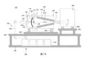
圖1A係繪示一種極紫外光微影系統101的示意圖。極紫外光微影系統101包含用以產生極紫外光的極紫外光輻射源設備100、例如掃描機的曝光工具200、和激發雷射源設備300。如圖1A所示,在一些實施方式中,極紫外光輻射源設備100和曝光工具200安裝在無塵室的主層MF上,而激發雷射源設備300安裝在位於主層下方的底層BF中。極紫外光輻射源設備100和曝光工具200中的每一個分別經由阻尼器DP1和DP2放置在基座板PP1和PP2上。通過可能包含聚焦單元的連接機構,極紫外光輻射源設備100和曝光工具200彼此連接。FIG1A is a schematic diagram of an
微影系統是一種極紫外光(EUV)微影系統,設計用於通過極紫外光(或極紫外光輻射EUV)曝光光阻層。光阻層是對極紫外光敏感的材料。極紫外光微影系統採用極紫外光輻射源設備100來產生極紫外光,例如具有波長範圍在約1nm和約100nm之間的極紫外光。在一個特定實施例中,極紫外光輻射源100產生具有波長集中在約13.5nm的極紫外光。在本實施方式中,極紫外光輻射源100利用雷射激發電漿(LPP)的機制來產生極紫外光輻射EUV。The lithography system is an extreme ultraviolet (EUV) lithography system designed to expose a photoresist layer by extreme ultraviolet light (or extreme ultraviolet radiation EUV). The photoresist layer is a material that is sensitive to extreme ultraviolet light. The extreme ultraviolet lithography system uses an extreme ultraviolet
曝光工具200包含各種反射光學元件,例如凸/凹/平鏡;包括光罩台的光罩支持機構;以及晶圓支持機構。極紫外光輻射源100產生的極紫外光輻射EUV被反射光學元件導引到固定在光罩台上的光罩上。在一些實施方式中,光罩台包含用於固定光罩的靜電卡盤(e-chuck)。由於氣體分子吸收極紫外光,因此用於極紫外光微影圖案化的微影系統保持在真空或低壓環境中,以避免極紫外光強度損失。The
圖1B係繪示依照本揭露之實施方式的曝光工具200的簡化示意圖,顯示出用圖案化的極紫外光束曝光塗覆有光阻的基板211。曝光工具200是積體電路微影工具,例如步進機、掃描機、步進掃描系統、直寫系統、使用接觸及/或近接光罩的裝置等,設有一個或多個光學儀器205a與205b,例如用極紫外光束照射圖案化之光學儀器,例如倍縮光罩205c,以產生圖案化光束;以及一個或多個縮小投影之光學儀器205d與205e,用於將圖案化光束投射到基板211。一個或多個光學儀器205a與205b提供具有期望剖面形狀和期望角分布的極紫外光束。倍縮光罩205c由光罩防塵護膜保護,光罩防塵護膜由光罩防塵護膜框架固定在適當處。倍縮光罩205c反射並圖案化極紫外光束。FIG1B is a simplified schematic diagram of an
請參閱圖1C,係繪示倍縮光罩205c的剖面圖。在一些實施方式中,倍縮光罩205c是反射式光罩。倍縮光罩205c包括低熱膨脹玻璃基板270,其上形成有Si和Mo的反射多層275。覆蓋層280和吸收層285形成在反射多層275上。後導電層290形成在低熱膨脹玻璃基板270的背面。在極紫外光(EUV)微影中,極紫外輻射以約6°的入射角朝向倍縮光罩205c。一部分之極紫外輻射被Si/Mo多層275反射至塗有光阻的基板211(圖1B),而入射到吸收層285上的極紫外輻射的部分被倍縮光罩205c吸收。在一些實施方式中,包括反射鏡的額外光學儀器位於反射光罩205c和塗有光阻的基板211之間。Please refer to FIG. 1C , which is a cross-sectional view of the
倍縮光罩205c包括光罩防塵護膜252,作為保護罩。光罩防塵護膜252能保護基板的圖案化表面256(也稱為正面)上的圖案免受損壞及/或汙染微粒。光罩防塵護膜252可以是覆蓋倍縮光罩205c的圖案化表面256的框架上的薄膜。光罩防塵護膜框架254圍繞光罩防塵護膜252的周圍部分並可移除地附接到倍縮光罩205c。The
請參閱圖1B,在倍縮光罩205c反射之後,將圖案化的極紫外光束提供給一個或多個光學儀器205d與205e,並且依次投射到由機械組件(例如,基板台)支撐的基板211上。在一些實施方式中,一個或多個光學儀器205d與205e應用縮減因子至輻射束,形成特徵小於倍縮光罩205c上對應特徵的圖像。可提供機械組件用於在基板211和倍縮光罩205c之間產生受控的相對運動。Referring to FIG. 1B , after reflection from a
極紫外光微影系統可例如以掃描模式使用,其中同步掃描卡盤和機械組件(例如,基板台),同時將輻射束賦予的圖案投射至基板211(即動態曝光)。基板台相對於卡盤的速度和方向由曝光工具200的倍縮和圖像反轉特性來決定。入射到基板211上的圖案化的極紫外光輻射束包含輻射帶。輻射帶稱為曝光狹縫。在掃描曝光期間,基板台和卡盤的移動使得曝光狹縫在基板211的曝光區域上行進。進一步如圖1B所示,EUVL工具包括極紫外光輻射源100,其包含在腔室105中發射極紫外光的在激發區ZE處的電漿,極紫外光由收集器110收集並反射而沿著路徑進入曝光工具200以照射基板211。The EUV lithography system can be used, for example, in a scanning mode, where the chuck and mechanical assembly (e.g., substrate stage) are scanned synchronously while projecting a pattern imparted by the radiation beam onto the substrate 211 (i.e., dynamic exposure). The speed and direction of the substrate stage relative to the chuck are determined by the magnification and image inversion characteristics of the
如本文所用,用語「光學儀器」意在廣義地解釋為包括但無需限於反射及/或透射及/或對入射光進行操作的一個或多個組件,並且包括但不限於一個或多個透鏡、窗、濾光片、楔形稜鏡、稜鏡、稜鏡光柵、光柵、傳輸光纖、分光器、擴散片、均質器、偵測器和其他儀器部件、孔徑、軸稜錐和反射鏡,反射鏡包括多層反射鏡、近垂直入射反射鏡、切線入射鏡、鏡面反射鏡、漫射鏡及其組合。此外,除非另有說明,否則此處使用的用語「光學儀器」不是意味限於僅在一個或多個特定波長範圍內,例如極紫外光輸出光波長、輻射雷射波長、適合度量衡學的波長或任何其他特定波長,工作的元件。As used herein, the term "optical instrument" is intended to be broadly interpreted to include but not necessarily be limited to one or more components that reflect and/or transmit and/or operate on incident light, and includes but is not limited to one or more lenses, windows, filters, wedge-shaped prisms, prisms, prism gratings, gratings, transmission fibers, beam splitters, diffusers, homogenizers, detectors and other instrument components, apertures, axial prisms and reflectors, including multi-layer reflectors, near-normal incidence reflectors, grazing incidence mirrors, mirror reflectors, diffusers and combinations thereof. Furthermore, unless otherwise specified, the term "optical instrument" as used herein is not intended to limit components to operating only within one or more specific wavelength ranges, such as extreme ultraviolet output light wavelengths, radiation laser wavelengths, wavelengths suitable for metrology, or any other specific wavelengths.
在本實施方式中,半導體基板是半導體晶圓,例如矽晶圓或待圖案化的其他類型的晶圓。在本實施方式中,半導體基板塗有對極紫外光敏感的光阻層。將包括上述那些的各種元件整合在一起,且這些元件可操作以執行微影曝光製程。In this embodiment, the semiconductor substrate is a semiconductor wafer, such as a silicon wafer or other type of wafer to be patterned. In this embodiment, the semiconductor substrate is coated with a photoresist layer that is sensitive to extreme ultraviolet light. Various components including those described above are integrated together and are operable to perform a lithography exposure process.
微影系統可進一步包括其他模組或其他模組整合(或耦接)。如圖1A所示,極紫外光輻射源100包括為腔室105圈圍的標靶液滴產生器115和雷射激發電漿收集器110。標靶液滴產生器115產生多個標靶液滴DP。在一些實施方式中,標靶液滴DP是錫(Sn)液滴。在一些實施方式中,每個錫液滴具有約30微米(μm)的直徑。在一些實施方式中,錫液滴DP以約每秒50滴的速率產生,並以約每秒70公尺(m/s)的速度引入激發區ZE。其他材料也可用於標靶液滴,例如含錫液體材料,例如含錫或鋰(Li)的共晶合金。The lithography system may further include other modules or other module integrations (or couplings). As shown in FIG. 1A , the extreme
激發雷射源設備300產生的激發雷射LR2是脈衝雷射。激發雷射LR2由激發雷射源300產生。雷射源300可包括雷射產生器310、雷射導引光學儀器320和聚焦設備330。在一些實施方式中,雷射產生器310包括二氧化碳(CO2)或摻釹釔鋁柘榴石雷射源。激發雷射源設備300產生的雷射光LR1由雷射導引光學儀器320導引並被聚焦設備330聚焦到激發雷射LR2,接著被引入極紫外光輻射源100。The excitation laser LR2 generated by the excitation
電漿發射由收集器110收集的極紫外光輻射EUV。收集器110具有反射面,反射並聚焦極紫外光輻射EUV以用於微影曝光製程。在一些實施方式中,液滴接收器120安裝在標靶液滴產生器115的對面。液滴接收器120用以接收多餘的標靶液滴。例如,一些標靶液滴可能被雷射脈衝故意遺漏。The plasma emits extreme ultraviolet radiation EUV which is collected by the
如圖1A所示,在一些實施方式中,緩衝氣體從第一緩衝氣體供應件130提供並通過收集器110的孔,脈衝雷射通過孔被傳送至錫液滴。在一些實施方式,緩衝氣體是H2、He、Ar、N2或另外的惰性氣體。緩衝器體也可以經由朝向收集器110及/或圍繞收集器110的邊緣的一個或多個第二緩衝氣體供應件135提供。此外,腔室105包括一個或多個氣體出口140,使得緩衝氣體排出腔室105外。為了捕捉腔室105中產生的碎屑,在腔室105中採用一個或多個碎屑收集機構或裝置150As shown in FIG. 1A , in some embodiments, a buffer gas is provided from a first
圖2繪示根據實施方式的倍縮光罩處理系統201的不同階段(或站)的布局示意圖。在一些實施方式中,倍縮光罩處理系統201用於極紫外光(EUV)微影系統中。倍縮光罩處理系統201結合曝光工具200以接收並儲存倍縮光罩205c,然後將倍縮光罩205c提供給曝光工具200以暴露於極紫外光輻射束。如圖所示,倍縮光罩處理系統201包括負載端202、外真空操作機(OVR)204、倍縮光罩背面檢查機(RBI)台206、條碼讀取器208、內真空操作機(IVR)210、內真空庫(IVL)212、快速交換裝置(RED)214和倍縮光罩台(RS)216(例如,包括倍縮光罩205c)。負載端202和外真空操作機(OVR)204位在大氣壓力環境中,而倍縮光罩背面檢查機(RBI)台206、條碼讀取器208、內真空操作機(IVR)210、內真空庫(IVL)212、快速交換裝置(RED)214和倍縮光罩台(RS)216位在真空環境中。真空環境與大氣壓力環境之間的通道是由負載鎖定室218控制。例如,負載鎖定室218位在外真空操作機(OVR)204與內真空庫(IVL)212之間。FIG2 is a schematic diagram showing the layout of different stages (or stations) of a
負載端202作為倍縮光罩處理系統201的入口點,倍縮光罩(例如圖1B中的倍縮光罩205c)經由入口點引入倍縮光罩處理系統201。在一些實施方式中,鄰近負載端202是RSP庫。RSP庫是多個倍縮光罩標準製造介面倉的儲存庫或儲存器,每個倍縮光罩標準製造介面倉都包括一個倍縮光罩。在一些實施方式中,外真空操作機(OVR)204取回倍縮光罩標準製造介面倉,其包含所需光罩以提供倍縮光罩給負載鎖定室218。真空泵連接負載鎖定室218並在負載鎖定室218中形成真空環境。倍縮光罩背面檢查機(RBI)台206位於鄰近負載鎖定室218,並包括測量和清潔倍縮光罩205c背面的設備,以限制在倍縮光罩205c背面上的微粒。條碼讀取器208辨識倍縮光罩205c和形成於其上的圖案。內真空操作機(IVR)210鄰近負載鎖定室218,且操作以將倍縮光罩205c從負載鎖定室218傳送至內真空庫(IVL)212,以在使用前暫時儲存倍縮光罩205c。在使用微影設備製造積體電路的過程中,使用不同的倍縮光罩205c來產生不同的電路圖案,並形成在積體電路的不同層上。倍縮光罩台216包括支撐結構,例如卡盤,用以在微影製程中適當的固定倍縮光罩205c。光罩防塵護膜252定位於倍縮光罩205c上,以保護倍縮光罩205c免受微粒、灰塵、損壞及/或汙染物。The
新製造的倍縮光罩(新下線)的圖案化表面,例如新製造的、以前未使用過的倍縮光罩205c,被碳氫化合物汙染。碳氫化合物汙染發生在圖案化表面256,並因倍縮光罩205c在製造期間經歷的不同處理(例如,使用有機材料)。碳氫化合物汙染物包括圖案化表面256上的單層氫分子和碳分子。碳氫化合物汙染降低或以其他方式降低倍縮光罩205c的圖案化表面256的反射性,讓反射程度低於新倍縮光罩205c的通常預期。降低的反射率導致製造錯誤。應當理解,當光罩防塵護膜252在倍縮光罩205c上方時,相似的碳氫化合物汙染發生在光罩防塵護膜252的表面上,並且本文中關於倍縮光罩205c的圖案化表面256上的汙染的討論同樣適用於光罩防塵護膜252表面上的汙染,為了簡潔起見在此省略。The patterned surface of a newly manufactured reticle (new off the line), such as a newly manufactured, previously
在曝光工具200中使用新倍縮光罩205c之前,獲得新倍縮光罩的參考圖像,也稱為金色圖像。在一些實施方式中,在安裝光罩防塵護膜252之前可掃描新倍縮光罩(倍縮光罩205c)。在一些實施方式中,通過反射光學儀器檢查工具可掃描倍縮光罩205c,並從倍縮光罩205c的圖案化表面256產生反射光。圖像由光學儀器檢查工具產生,並將倍縮光罩205c的圖案中的圖案元素繪成深灰色背景上的淺灰色。即獲得圖像的不同部分具有不同灰階強度(灰階值),因此獲得的圖像稱為灰階圖像。圖3A繪示倍縮光罩205c的示範灰階圖像351。Before using the
現在,曝光工具200包括倍縮光罩205c暴露於其中的氫氣。例如,氫氣從腔室105(如圖1A)進入曝光工具200,而在曝光工具200中產生含氫環境。氫離子的一種來源是在曝光工具200中執行的高能處理,例如極紫外光微影。在一些例子中,倍縮光罩205c在儲存在倍縮光罩處理系統201中時也暴露於含氫環境。隨著時間,隨著具有碳氫化合物汙染的倍縮光罩205c暴露於含氫環境,氫氣結合倍縮光罩205c上的氫和碳汙染物而產生氣體(CxHy),然後從曝光工具200中排出。此反應因此減少了倍縮光罩表面上的碳氫化合物汙染物。由於碳氫化合物汙染物的減少,倍縮光罩205c的反射率增加。Now,
因此,倍縮光罩205c在暴露於含氫環境後的反射率,高於倍縮光罩205c在暴露之前的反射率。換句話說,曝光後的倍縮光罩205c的灰階圖像強度高於曝光前的灰階圖像強度。Therefore, the reflectivity of the
檢查倍縮光罩205c,以確定在倍縮光罩205c暴露於含氫環境期間、同時或之後產生的缺陷或汙染程度。在一實施例中,缺陷包括由於掉落引起的缺陷或由例如光阻引起的環境氫和碳或氫之間的反應而引起的汙染。檢查時,對倍縮光罩205c進行成像,例如得到倍縮光罩205c的灰階圖像。然後比較灰階圖像與先前取得的倍縮光罩205c的金色圖像。基於灰階圖像的差異,可以確定倍縮光罩205c中的缺陷或汙染程度。然而,如上所述,倍縮光罩205c的反射率在處於曝光工具中之後而增加。因此,參考(金色)圖像的倍縮光罩反射率是對倍縮光罩實際反射率的錯誤測量。由於曝光前後灰階強度之間的顯著不匹配,灰階強度的差異導致明暗問題。由於不匹配,倍縮光罩曝光後,倍縮光罩上較暗的位置會顯得很亮(明暗問題)。由於明暗問題,時間延遲和整合(TDI)感測器捕獲突然的信號強度變化,並且無法補償灰階差異。The
圖3B繪示了使用光學檢驗工具獲得的曝光前(金色圖像)和曝光後倍縮光罩205c的灰階強度差異。如圖所示,曝光前倍縮光罩205c的灰階強度(由跡線302所指示)與曝光後倍縮光罩205c的灰階強度(由跡線304指示)之間的差異相對較高。因為灰階強度的差異,金色圖像需要經常重新校準,或在一些情況下,需要獲得新的金色圖像。換句話說,金色圖像的可靠性降低了。重新校準金色圖像並獲得新的金色圖像會影響極紫外光檢驗工具的可用性,進而影響生產。因此希望減少灰階強度的差異並也延長金色圖像的壽命。FIG3B illustrates the difference in grayscale intensity of the
本揭露的實施方式涉及在獲得金色圖像之前通過去除碳氫化合物汙染來淨化倍縮光罩。結果,獲得的金色圖像更接近地指示具有最小汙染的倍縮光罩的灰階強度。在一個實施方式中,使用氫自由基產生器(HRG)來產生氫原子,以清潔碳氫化合物汙染層。根據實施方式,曝光工具(例如,曝光工具200)及/或倍縮光罩處理系統201設置或流體地耦合到倍縮光罩檢驗工具和氫自由基產生器,使得倍縮光罩的檢驗和清潔可原位進行,即不從曝光工具移除倍縮光罩。雖然減少碳氫化合物汙染以獲得正確的倍縮光罩反射率是有益的,但是通過暴露於曝光工具中的含氫環境所獲得的反射率恢復(增加)是一個較慢的過程,發生在相對較長的時間段內。因此灰階程度的增加較慢。藉由使用氫自由基產生器用氫處理倍縮光罩,與缺少氫處理的速度和時間相比,灰階程度增加快速且灰階程度在相對短的時間內變的穩定。通過氫處理的倍縮光罩得到的新色圖像具有相對較長的壽命,因此重新校準的金色圖像或得到的新圖像的頻率較低。Embodiments of the present disclosure relate to cleaning a reticle by removing hydrocarbon contamination before obtaining a gold image. As a result, the obtained gold image more closely indicates the grayscale intensity of the reticle with minimal contamination. In one embodiment, a hydrogen radical generator (HRG) is used to generate hydrogen atoms to clean the hydrocarbon contamination layer. According to an embodiment, an exposure tool (e.g., exposure tool 200) and/or a
圖4示意地繪示了相對於倍縮光罩205c的氫自由基產生器(HRG)400。氫自由基產生器400可以接近或鄰近要去汙的倍縮光罩205c,或者可以遠離倍縮光罩205c,而氫自由基從氫自由基產生器傳送到需要去汙的倍縮光罩205c(例如,藉由適當的流動、擴散及/或通過導管等)。根據實施方式,氫自由基產生器流體連接曝光工具及/或檢驗工具,為了允許氫自由基從氫自由基產生器傳送到曝光工具及/或倍縮光罩檢驗工具,及/或其中包含的光學元件。FIG4 schematically illustrates a hydrogen radical generator (HRG) 400 relative to a
氫自由基產生器400包括包含金屬絲454的隔間452。金屬絲454可例如是鎢,或可承受產生氫自由基所需的溫度的任何其他金屬。The hydrogen
控制器456連接、控制和驅動金屬絲454。控制器456藉由提供並通過金屬絲454的驅動電流的適當控制,來控制金屬絲454的溫度。控制器456被顯示為位於隔間452的外部,但在其他實施方式中可以位於隔間452內,或形成隔間452的一部分。The
隔間452設置入口458和出口460,以分別允許氣體等(例如微粒、原子和分子)進出隔間452。雖然沒有顯示在圖4中,氫自由基產生器400可設置或結合一個或多個泵使用,以將氣體等吸入或吹入氫自由基產生器400及/或從氫自由基產生器400中排出氣體。在圖4中,出口460被顯示為指向倍縮光罩250c。然而,在其他實施方式中,其他配置可以是可能的或期望的。例如,一根或多根管子或導管等可將氣體等從氫自由基產生器導引至一個或多個光學元件或其他部分。The
使用時,氫分子462被引入或吸入隔間452並通過(例如,通過及/或圍繞)金屬絲454。當金屬絲454的溫度為霧化溫度(例如1300°C-2500°C),足以霧化氫分子462並產生氫自由基464以淨化倍縮光罩205c。設置抽取點468(在此實施例中,鄰近倍縮光罩205c,儘管可使用其他位置)以抽取氫,氫自由基464及/或通過氫自由基464從倍縮光罩205c去除和在曝光工具/檢驗工具之外的任何汙染物(例如,氣體(CxHy))。In use,
圖5A示意地繪示了氫自由基產生器400、曝光工具200、檢驗工具700和倍縮光罩處理系統201之間的連接。曝光工具200和倍縮光罩處理系統201彼此流體連通,因為倍縮光罩205c暴露在這些組件中的含氫環境中。雖然將氫自由基產生器400、曝光工具200、檢驗工具700和倍縮光罩處理系統201圖示為單獨元件,但是氫自由基產生器400、曝光工具200、檢驗工具700和倍縮光罩處理系統201中二個或更多個能組合成一個單獨的元件。例如,檢驗工具700、曝光工具200、和氫自由基產生器400能組合在倍縮光罩處理系統201與其流體連通的一個單獨殼體中。5A schematically illustrates the connection between the hydrogen
圖5B是顯示根據實施方式的半導體裝置製造中的不同製程的流程圖。在S502,獲得新的、先前未使用的倍縮光罩(例如,倍縮光罩205c)。在一些實施方式中,將倍縮光罩放置在塑料袋包裹的倍縮光罩盒中。在S504,從倍縮光罩盒移除倍縮光罩之後(並且在倍縮光罩進行任何極紫外光曝光之前),使用氫自由基產生器淨化倍縮光罩的表面。使用時,金屬絲454的溫度約為1300℃至2500℃,足以霧化氫分子462並產生氫自由基464。操作中,氫自由基產生器400中的壓力可以為約5·10毫巴至7毫巴。假如光罩防塵護膜呈現在倍縮光罩上,消除汙染物是從光罩防塵護膜表面去除碳氫化合物汙染物。在S506接著獲得倍縮光罩的金色或參考圖像。消除汙染物是移除碳氫化合物單層並提高倍縮光罩的反射率。這種倍縮光罩的金色圖像更類似於倍縮光罩的實際反射率,並且與未經處理的倍縮光罩相比,消除汙染物的倍縮光罩在曝光工具中的長時間曝光,不會顯著增加倍縮光罩的反射率。因此,金色圖像需要重新校準的頻率較低。在S508,提供倍縮光罩給曝光工具(例如,曝光工具200)或倍縮光罩處理系統201,以用於製造半導體裝置。當不使用時,倍縮光罩儲存在倍縮光罩處理系統201中,例如在內真空庫(IVL)212中。在S510,檢驗倍縮光罩的缺陷。在此過程中,取得倍縮光罩的灰階圖像,並將此灰階圖像與S506中取得的金色圖像進行比較,以確定金色圖像中的灰階值與取得的灰階圖像中的灰階值之間的差異。如果差異大於特定數值,則判斷倍縮光罩有缺陷或不良的汙染程度。如果差異小於或等於特定數值,則判斷倍縮光罩沒有缺陷。由於在S506取得的金色圖像類似於倍縮光罩的實際反射率,並因為當暴露於曝光工具中的環境或倍縮光罩處理系統中的環境時,金色圖像的反射率沒有改變(或僅變化很小),可以重複使用相同的金色圖像進行比較。因此,金色圖像不需要重複重新校準,或者新的金色圖像可能需要不頻繁的生成。因此,金色圖像的壽命增加了。重新校準現有的金色圖像或取得新的金色圖像是一個耗時的過程,需要停止檢驗工具及/或曝光工具。因此,生產受到影響且成本增加。藉由使用本文揭露的實施方式來增加金色圖像的壽命,可最小化生產中斷且生產成本保持在最小。5B is a flow chart showing different processes in semiconductor device fabrication according to an embodiment. At S502, a new, previously unused reticle (e.g.,
在一些實施方式中,代替使用氫自由基產生器,倍縮光罩可以使用其他技術,例如臭氧處理、熱清潔、和感應耦合式電漿-反應性離子蝕刻(ICP-RIE)來淨化。臭氧處理包括在紫外光下將倍縮光罩暴露於臭氧,以去除碳氫化合物汙染物。感應耦合式電漿-反應性離子蝕刻產生電漿,用於蝕刻掉碳氫化合物汙染物。In some embodiments, instead of using a hydrogen radical generator, the photomask can be cleaned using other techniques such as ozone treatment, thermal cleaning, and inductively coupled plasma-reactive ion etching (ICP-RIE). Ozone treatment involves exposing the photomask to ozone under ultraviolet light to remove hydrocarbon contaminants. Inductively coupled plasma-reactive ion etching generates a plasma that is used to etch away hydrocarbon contaminants.
圖6係繪示依照一些實施方式之用於控制根據實施例中圖1A、圖1B和圖2所示的極紫外光輻射源設備100、曝光工具200、氫自由基產生器400及/或倍縮光罩處理系統201之操作,以及進行其他任務,例如取得金色圖像、檢查晶圓等的示例計算裝置610的方塊圖。在一些實施方式中,計算裝置610使用硬體或軟體和硬體的組合來實現,或者在專屬伺服器中,整合到另一個實體中,或者分佈在多個實體中。6 is a block diagram of an example computing device 610 for controlling the operation of the extreme ultraviolet
計算裝置610使用無線或有線網路640而可通信地連接到極紫外光輻射源設備100、曝光工具200及/或倍縮光罩處理系統201,並以允許它們之間的數據619交換。The computing device 610 is communicatively connected to the EUV
計算裝置610包括顯示器611、處理器612、記憶體613、輸入/輸出介面614、網路介面615、和儲存器616,儲存器616儲存作業系統617、程式或應用程式618,例如用於控制極紫外光輻射源設備100、曝光工具200、和/及倍縮光罩處理系統201之應用程式。處理器612可為通用型微處理器、微控制器、數位訊號處理器(DSP)、特殊應用積體電路(ASIC)、場效可程式化閘極陣列(FPGA)、可程式化邏輯裝置(PLD)、控制器、狀態機、閘控邏輯、離散硬體元件或任何其他可以執行計算或其他資訊操作的合適實體。儲存器616可為隨機存取記憶體(RAM)、快閃記憶體、唯讀記憶體(ROM)、可程式化唯讀記憶體(PROM)、抹除式可程式化唯讀記憶體(EPROM)、紀錄器、硬碟、可移硬碟、a CD-ROM、a DVD、或任何其他合適的儲存裝置,用於儲存由處理器612執行的資訊和指令。處理器612和儲存器616可由特殊用途邏輯電路補充或併入特殊用途邏輯電路中。The computing device 610 includes a display 611, a processor 612, a memory 613, an input/output interface 614, a network interface 615, and a
網路介面615包括網路介面卡,例如乙太網路卡和數據機。在一些實施方式中,輸入/輸出介面614配置以連接到多個裝置,例如輸入裝置及/或輸出裝置。示範輸入裝置包括鍵盤和定點裝置,例如滑鼠或軌跡球,使用者可以通過它們向計算裝置610提供輸入。其他類型的輸入裝置也用於提供與使用者互動,例如觸覺輸入裝置、視覺輸入裝置、聲音輸入裝置或人機介面裝置。例如,提供給使用者的反饋可為任何形式的感官反饋,例如視覺反饋、聽覺反饋或觸覺反饋;並且可以任何形式接收來自使用者的輸入,包括聲音、語音、觸覺或腦波輸入。示範輸出裝置包括顯示裝置,例如LED(發光二極體)、CRT(陰極射線管)或LCD(液晶顯示器)螢幕,用於向使用者顯示訊息。The network interface 615 includes a network interface card, such as an Ethernet card and a modem. In some embodiments, the input/output interface 614 is configured to connect to multiple devices, such as input devices and/or output devices. Exemplary input devices include keyboards and pointing devices, such as a mouse or trackball, through which a user can provide input to the computing device 610. Other types of input devices are also used to provide interaction with the user, such as tactile input devices, visual input devices, voice input devices, or human-computer interface devices. For example, the feedback provided to the user may be any form of sensory feedback, such as visual feedback, auditory feedback, or tactile feedback; and the input from the user may be received in any form, including sound, voice, tactile, or brain wave input. Exemplary output devices include display devices, such as LED (light emitting diodes), CRT (cathode ray tubes), or LCD (liquid crystal display) screens, for displaying information to the user.
應用程式618可包括指令,當指令由計算裝置610(或其處理器612)執行時,使計算裝置610(或其處理器612)控制極紫外光輻射源設備100,曝光工具200及/或倍縮光罩處理系統201,獲得金色圖像,檢查晶片,並執行在本揭露中明確或隱含描述的其他操作、方法及/或製程。The application 618 may include instructions that, when executed by the computing device 610 (or its processor 612), cause the computing device 610 (or its processor 612) to control the extreme ultraviolet
數據619可包括包含在控制操作中使用的預設參數的數據,例如通過輸入/輸出介面614或通過網路介面615從極紫外光輻射源設備100、曝光工具200及/或倍縮光罩處理系統201發送並顯示在顯示器上的數據、經由網路640傳輸至極紫外光輻射源設備100、曝光工具200及/或倍縮光罩處理系統201的數據,或在計算設備610的操作期間生成的數據。Data 619 may include data including preset parameters used in control operations, such as data sent from the extreme ultraviolet
本揭露的實施方式有利地改善倍縮光罩(光罩)使用在曝光工具中之前的倍縮光罩的反射率。結果,倍縮光罩的壽命大大地增加,生產停工時間和成本也減少。應當理解,並非所有優點都必須在本文中進行討論,所有實施方式或實施例都不需要特定的優點,並且其他實施方式或實施例可以提供不同的優點。Embodiments of the present disclosure advantageously improve the reflectivity of a reticle (mask) prior to use in an exposure tool. As a result, the life of the reticle is greatly increased, and production downtime and costs are reduced. It should be understood that not all advantages must be discussed herein, that all embodiments or implementations do not require a particular advantage, and that other embodiments or implementations may provide different advantages.
根據本揭露的一些實施方式,缺陷檢驗方法包括接收新光罩,通過將新光罩的表面暴露於氫自由基來減少新光罩的表面的汙染物,取得新光罩的第一灰階圖像,將新光罩暴露於極紫外光微影系統的含氫環境,取得新光罩的第二灰階圖像,比較第二灰階圖像與第一灰階圖像以確定新光罩中的汙染程度。根據實施方式,將新光罩暴露於含氫環境中包含將新光罩暴露於極紫外光微影系統的曝光工具中之含氫環境中。根據實施方式,使用流體耦合曝光工具的氫自由基產生器來產生氫自由基。根據實施方式,將新光罩暴露於含氫環境中包含將新光罩暴露於極紫外光微影系統的倍縮光罩處理系統中之含氫環境中。根據實施方式,使用流體耦合倍縮光罩處理系統的氫自由基產生器來產生氫自由基。根據實施方式,方法更包括重新校準第一灰階圖像,及比較第二灰階圖像與已經重新校準的第一灰階圖像以確定汙染程度。根據實施方式,方法更包括取得新光罩的新灰階圖像,及比較第二灰階圖像與新灰階圖像。根據實施方式,取得新光罩的第一灰階圖像與第二灰階圖像中更包括利用光學檢驗工具掃描新光罩的表面,以產生自新光罩的表面反射的反射光,及根據反射光取得新光罩的灰階圖像。根據實施方式,新光罩是新下線之後和暴露極紫外光微影系統的含氫環境之前的光罩。根據實施方式,通過將新光罩的表面暴露於氫自由基來減少新光罩的表面的汙染物中,減少新光罩暴露在含氫環境之前與之後的灰階強度差異。According to some embodiments of the present disclosure, a defect inspection method includes receiving a new mask, reducing contaminants on the surface of the new mask by exposing the surface of the new mask to hydrogen radicals, obtaining a first grayscale image of the new mask, exposing the new mask to a hydrogen-containing environment of an extreme ultraviolet lithography system, obtaining a second grayscale image of the new mask, and comparing the second grayscale image with the first grayscale image to determine the degree of contamination in the new mask. According to embodiments, exposing the new mask to a hydrogen-containing environment includes exposing the new mask to a hydrogen-containing environment in an exposure tool of the extreme ultraviolet lithography system. According to embodiments, hydrogen radicals are generated using a hydrogen radical generator of a fluid-coupled exposure tool. According to an embodiment, exposing the new mask to a hydrogen-containing environment includes exposing the new mask to a hydrogen-containing environment in a multiplication mask processing system of an extreme ultraviolet lithography system. According to an embodiment, a hydrogen radical generator of the fluid-coupled multiplication mask processing system is used to generate hydrogen radicals. According to an embodiment, the method further includes recalibrating the first grayscale image, and comparing the second grayscale image with the recalibrated first grayscale image to determine the degree of contamination. According to an embodiment, the method further includes obtaining a new grayscale image of the new mask, and comparing the second grayscale image with the new grayscale image. According to the implementation manner, obtaining the first grayscale image and the second grayscale image of the new mask further includes scanning the surface of the new mask using an optical inspection tool to generate reflected light reflected from the surface of the new mask, and obtaining the grayscale image of the new mask based on the reflected light. According to the implementation manner, the new mask is a mask after it is newly offline and before it is exposed to the hydrogen-containing environment of the extreme ultraviolet lithography system. According to the implementation manner, by exposing the surface of the new mask to hydrogen free radicals to reduce contaminants on the surface of the new mask, the grayscale intensity difference before and after the new mask is exposed to the hydrogen-containing environment is reduced.
根據本揭露的一些實施方式,缺陷檢驗方法包括接收新光罩,通過將新光罩的表面暴露於氫自由基來減少新光罩的表面的汙染物,取得新光罩的第一灰階圖像,使用新光罩將極紫外光輻射束照射到放置在曝光工具中的基板上,在極紫外光輻射束照射後,取得新光罩的第二灰階圖像,確定極紫外光輻射束照射之前和之後的新光罩的灰階強度差異,基於灰階強度差異確定新光罩的汙染程度。根據實施方式,在使用新光罩將極紫外光輻射束照射到放置在曝光工具中的基板上中,將新光罩暴露在含氫環境。根據實施方式,使用流體耦合曝光工具的氫自由基產生器來產生氫自由基。根據實施方式,使用流體耦合到曝光工具的檢驗工具來進行確定以極紫外光輻射束照射之前和之後的新光罩的灰階強度差異。根據實施方式,取得新光罩的第一灰階圖像與第二灰階圖像中更包含利用光學檢驗工具掃描新光罩的表面,以產生自新光罩的表面反射的反射光,及根據反射光取得新光罩的灰階圖像。根據實施方式,新光罩是新下線之後和放置在曝光工具之前的光罩。根據實施方式,方法更包括取得新光罩的新灰階圖像,及比較第二灰階圖像與新灰階圖像。According to some embodiments of the present disclosure, a defect inspection method includes receiving a new mask, reducing contaminants on the surface of the new mask by exposing the surface of the new mask to hydrogen radicals, obtaining a first grayscale image of the new mask, irradiating an extreme ultraviolet radiation beam onto a substrate placed in an exposure tool using the new mask, obtaining a second grayscale image of the new mask after the extreme ultraviolet radiation beam irradiation, determining a grayscale intensity difference of the new mask before and after the extreme ultraviolet radiation beam irradiation, and determining a contamination level of the new mask based on the grayscale intensity difference. According to an embodiment, in irradiating an extreme ultraviolet radiation beam onto a substrate placed in an exposure tool using the new mask, the new mask is exposed to a hydrogen-containing environment. According to an implementation manner, a hydrogen radical generator of a fluid-coupled exposure tool is used to generate hydrogen radicals. According to an implementation manner, an inspection tool that is fluid-coupled to the exposure tool is used to determine the grayscale intensity difference of the new mask before and after irradiation with an extreme ultraviolet radiation beam. According to an implementation manner, obtaining a first grayscale image and a second grayscale image of the new mask further includes using an optical inspection tool to scan the surface of the new mask to generate reflected light reflected from the surface of the new mask, and obtaining a grayscale image of the new mask based on the reflected light. According to an implementation manner, the new mask is a mask that is newly offline and placed before the exposure tool. According to an implementation manner, the method further includes obtaining a new grayscale image of the new mask, and comparing the second grayscale image with the new grayscale image.
根據本揭露的一些實施方式,缺陷檢驗設備包括氫自由基產生器,用以產生氫自由基,氫自由基暴露於新光罩的表面,用以淨化新光罩的表面。曝光工具耦合氫自由基產生器,曝光工具配置以接收使用氫自由基淨化之後的新光罩,並使用新光罩將極紫外光輻射束照射至放置在曝光工具中的基板。檢驗工具流體耦合氫自由基產生器和曝光工具,檢驗工具配置以在使用新光罩照射極紫外光輻射束之前與之後時,取得新光罩的灰階圖像,以及確定灰階圖像之間的差異。根據實施方式,淨化新光罩的表面,減少了在照射極紫外光輻射束之前與之後時的新光罩的灰階強度差異。根據實施方式,檢驗工具配置為比較新光罩的新灰階圖像與使用新光罩照射極紫外光輻射束的光罩的灰階圖像,並確定新灰階圖像與使用新光罩之後的新光罩的灰階圖像的灰階強度差異。According to some embodiments of the present disclosure, a defect inspection device includes a hydrogen radical generator for generating hydrogen radicals, which are exposed to the surface of a new mask to purify the surface of the new mask. An exposure tool is coupled to the hydrogen radical generator, and the exposure tool is configured to receive the new mask after purification using the hydrogen radicals, and to irradiate an extreme ultraviolet radiation beam onto a substrate placed in the exposure tool using the new mask. An inspection tool fluidly couples the hydrogen radical generator and the exposure tool, and the inspection tool is configured to obtain a grayscale image of the new mask before and after irradiating the extreme ultraviolet radiation beam using the new mask, and to determine the difference between the grayscale images. According to an embodiment, purifying the surface of the new mask reduces the difference in grayscale intensity of the new mask before and after irradiating the extreme ultraviolet radiation beam. According to an embodiment, the inspection tool is configured to compare the new grayscale image of the new mask with the grayscale image of the mask irradiated with the extreme ultraviolet radiation beam using the new mask, and determine the grayscale intensity difference between the new grayscale image and the grayscale image of the new mask after using the new mask.
上述已概述數個實施方式或實施例的特徵,因此熟習此技藝者可更了解本揭露之態樣。熟習此技藝者應了解到,其可輕易地利用本揭露做為基礎,來設計或潤飾其他製程與結構,以實現與在此所介紹之實施方式或實施例相同之目的及/或達到相同的優點。熟習此技藝者也應了解到,這類對等架構並未脫離本揭露之精神和範圍,且熟習此技藝者可在不脫離本揭露之精神和範圍下,在此進行各種之更動、取代、與修改。The above has summarized the features of several implementations or examples, so that those skilled in the art can better understand the state of the present disclosure. Those skilled in the art should understand that they can easily use the present disclosure as a basis to design or embellish other processes and structures to achieve the same purpose and/or achieve the same advantages as the implementations or examples introduced herein. Those skilled in the art should also understand that such equivalent architectures do not deviate from the spirit and scope of the present disclosure, and those skilled in the art can make various changes, substitutions, and modifications here without departing from the spirit and scope of the present disclosure.
100:極紫外光輻射源設備,極紫外光輻射源 101:極紫外光微影系統 105:腔室 110:收集器,雷射激發電漿收集器 115:標靶液滴產生器 120:液滴接收器 130:第一緩衝氣體供應件 135:第二緩衝氣體供應件 140:氣體出口 150:碎屑收集機構或裝置 200:曝光工具 201:倍縮光罩處理系統 202:負載端 204:外真空操作機 205a,205b:光學儀器 205c:倍縮光罩,反射光罩 205d,205e:光學儀器 206:倍縮光罩背面檢查機台 208:條碼讀取器 210:內真空操作機 211:基板 212:內真空庫 214:快速交換裝置 216:倍縮光罩台 218:負載鎖定室 252:光罩防塵護膜 254:光罩防塵護膜框架 256:圖案化表面 270:低熱膨脹玻璃基板 275:反射多層,Si/Mo多層 280:覆蓋層 285:吸收層 290:後導電層 300:激發雷射源設備, 激發雷射源,雷射源 302:跡線 304:跡線 310:雷射產生器 320:雷射導引光學儀器 330:聚焦設備 351:示範灰階圖像 400:氫自由基產生器 452:隔間 454:金屬絲 456:控制器 458:入口 460:出口 462:氫分子 464:氫自由基 468:抽取點 610:計算裝置 611:顯示器 612:處理器 613:記憶體 614:輸入/輸出介面 615:網路介面 616:儲存器 617:作業系統 618:應用程式 619:數據 640:網路 700:檢驗工具 BF:底層 DP:標靶液滴 DP1,DP2:阻尼器 MF:主層 PP1,PP2:基座板 LR2:激發雷射 EUV:極紫外光輻射100: Extreme ultraviolet radiation source equipment, extreme ultraviolet radiation source101: Extreme ultraviolet lithography system105: Chamber110: Collector, laser-induced plasma collector115: Target droplet generator120: Droplet receiver130: First buffer gas supply135: Second buffer gas supply140: Gas outlet150: Debris collection mechanism or device200: Exposure tool201: Zoom mask processing system202: Load end204: External vacuum manipulator205a, 205b: Optical instrument205c: Zoom mask, reflective mask205d, 205e: Optical instruments206: Back inspection machine for zoom mask208: Barcode reader210: Internal vacuum manipulator211: Substrate212: Internal vacuum warehouse214: Quick exchange device216: Zoom mask stage218: Load lock chamber252: Mask dust film254: Mask dust film frame256: Patterned surface270: Low thermal expansion glass substrate275: Reflective multilayer, Si/Mo multilayer280: Cover layer285: Absorption layer290: Back conductive layer300: Excitation laser source equipment, excitation laser source, laser source302: trace304: trace310: laser generator320: laser guide optics330: focusing device351: demonstration grayscale image400: hydrogen radical generator452: compartment454: metal wire456: controller458: inlet460: outlet462: hydrogen molecule464: hydrogen radical468: extraction point610: computing device611: display612: processor613: memory614: input/output interface615: network interface616: storage617: operating system618: application619: Data640: Network700: Inspection toolBF: Base layerDP: Target dropletDP1, DP2: DampersMF: Main layerPP1, PP2: Base plateLR2: LaserEUV: Extreme ultraviolet radiation
從以下結合所附圖式所做的詳細描述,可對本揭露之態樣有更佳的了解。需注意的是,根據業界的標準實務,各特徵並未依比例繪示。事實上,為了使討論更為清楚,各特徵的尺寸都可任意地增加或縮減。 圖1A係繪示依照本揭露之一些實施方式的一種具有雷射激發電漿(LPP)極紫外光(EUV)輻射源的極紫外光微影系統的示意圖。 圖1B係繪示依照本揭露之實施方式的極紫外光微影系統曝光工具的示意圖。 圖1C係繪示倍縮光罩的剖面示意圖。 圖2係繪示具有極紫外光微影系統的不同階段(或站)的示範布局的上視示意圖。 圖3A係繪示倍縮光罩的一示範灰階圖像。 圖3B係繪示使用光學檢驗工具獲得的曝光前(金色圖像)和曝光後的倍縮光罩的灰階強度差異。 圖4係示意性地繪示相對於倍縮光罩的一種氫自由基產生器。 圖5A係示意地繪示氫自由基產生器、曝光工具、檢驗工具和倍縮光罩處理系統之間的連接關係。 圖5B係依照實施例之表示半導體裝置製造中之不同製程的流程圖。 圖6係繪示根據實施例之用於控制圖1A、圖1B和圖2所示的極紫外光輻射源設備、曝光工具、氫自由基產生器及/或倍縮光罩處理系統的一操作的方塊圖。The present disclosure may be better understood from the following detailed description in conjunction with the accompanying drawings. It should be noted that, in accordance with standard industry practice, the features are not drawn to scale. In fact, the dimensions of the features may be arbitrarily increased or decreased for clarity of discussion.FIG. 1A is a schematic diagram of an EUV lithography system having a laser-induced plasma (LPP) EUV radiation source in accordance with some embodiments of the present disclosure.FIG. 1B is a schematic diagram of an EUV lithography system exposure tool in accordance with embodiments of the present disclosure.FIG. 1C is a schematic diagram of a cross-sectional view of a zoom mask.FIG. 2 is a schematic diagram of a top view of an exemplary layout of different stages (or stations) of an EUV lithography system.FIG. 3A shows an exemplary grayscale image of a multiplied mask.FIG. 3B shows the grayscale intensity difference of a multiplied mask before exposure (gold image) and after exposure obtained using an optical inspection tool.FIG. 4 schematically shows a hydrogen radical generator relative to a multiplied mask.FIG. 5A schematically shows the connection relationship between a hydrogen radical generator, an exposure tool, an inspection tool, and a multiplied mask processing system.FIG. 5B is a flow chart showing different processes in semiconductor device manufacturing according to an embodiment.FIG. 6 is a block diagram showing an operation of controlling the extreme ultraviolet radiation source equipment, exposure tool, hydrogen radical generator and/or multiplication mask processing system shown in FIG. 1A , FIG. 1B and FIG. 2 according to an embodiment.
國內寄存資訊(請依寄存機構、日期、號碼順序註記) 無 國外寄存資訊(請依寄存國家、機構、日期、號碼順序註記) 無Domestic storage information (please note in the order of storage institution, date, and number)NoneForeign storage information (please note in the order of storage country, institution, date, and number)None
200:曝光工具200:Exposure tools
201:倍縮光罩處理系統201: Reduction mask processing system
400:氫自由基產生器400: Hydrogen radical generator
700:檢驗工具700: Inspection tools
Claims (20)
Translated fromChineseApplications Claiming Priority (2)
| Application Number | Priority Date | Filing Date | Title |
|---|---|---|---|
| US202318110841A | 2023-02-16 | 2023-02-16 | |
| US18/110,841 | 2023-02-16 |
Publications (1)
| Publication Number | Publication Date |
|---|---|
| TW202434875Atrue TW202434875A (en) | 2024-09-01 |
Family
ID=93609604
Family Applications (1)
| Application Number | Title | Priority Date | Filing Date |
|---|---|---|---|
| TW112134265ATW202434875A (en) | 2023-02-16 | 2023-09-08 | Defect inspection method |
Country Status (1)
| Country | Link |
|---|---|
| TW (1) | TW202434875A (en) |
- 2023
- 2023-09-08TWTW112134265Apatent/TW202434875A/enunknown
Similar Documents
| Publication | Publication Date | Title |
|---|---|---|
| US7894037B2 (en) | Lithographic apparatus and device manufacturing method | |
| JP5586611B2 (en) | EUV lithographic apparatus and method for processing optical elements | |
| US10852649B2 (en) | Methods and apparatus for removing contamination from lithographic tool | |
| TWI420251B (en) | Lithographic apparatus, plasma source, and reflecting method | |
| US20080218709A1 (en) | Removal of deposition on an element of a lithographic apparatus | |
| CN110837204A (en) | Extreme ultraviolet lithography system | |
| US20250314958A1 (en) | Contaminant identification metrology system, lithographic apparatus, and methods thereof | |
| TWI826889B (en) | Apparatus and method for cleaning an inspection system | |
| US6980281B2 (en) | Lithographic apparatus and device manufacturing method | |
| TW202434875A (en) | Defect inspection method | |
| JP2005294834A (en) | Lithographic device and manufacturing method of device | |
| WO2002069379A1 (en) | X-ray reflective mask, method of protecting the reflective mask, x-ray exposure device, and method of manufacturing semiconductor device | |
| JP2024506526A (en) | Systems and methods for contaminant detection | |
| US20250020570A1 (en) | Photolithograph apparatus, method for inspecting particles and semiconductor process | |
| TWI860372B (en) | Surface treatment apparatus and method for surface treatment of patterning devices and other substrates | |
| US12216399B2 (en) | Method of manufacturing semiconductor device | |
| CN117098984B (en) | System and method for optical path coupling of in-situ photochemically cleaned light in projection imaging systems | |
| KR102868707B1 (en) | Surface treatment device and method for surface treatment of patterning devices and other substrates | |
| WO2022175025A1 (en) | Augmented reality (ar) assisted particle contamination detection | |
| WO2025141350A1 (en) | Laser beam aperture | |
| TW202437026A (en) | Patterning device loading method | |
| CN118265951A (en) | Optical device, irradiation system, projection system, EUV radiation source, photolithography equipment, contamination deposition prevention method and optical component refurbishment method | |
| KR20170096581A (en) | Machining apparatus |