TW202429379A - Method for processing review images and review system - Google Patents
Method for processing review images and review systemDownload PDFInfo
- Publication number
- TW202429379A TW202429379ATW112107210ATW112107210ATW202429379ATW 202429379 ATW202429379 ATW 202429379ATW 112107210 ATW112107210 ATW 112107210ATW 112107210 ATW112107210 ATW 112107210ATW 202429379 ATW202429379 ATW 202429379A
- Authority
- TW
- Taiwan
- Prior art keywords
- image
- defect
- inspection
- review
- images
- Prior art date
Links
Images


Classifications
- G—PHYSICS
- G01—MEASURING; TESTING
- G01N—INVESTIGATING OR ANALYSING MATERIALS BY DETERMINING THEIR CHEMICAL OR PHYSICAL PROPERTIES
- G01N21/00—Investigating or analysing materials by the use of optical means, i.e. using sub-millimetre waves, infrared, visible or ultraviolet light
- G01N21/84—Systems specially adapted for particular applications
- G01N21/88—Investigating the presence of flaws or contamination
- G01N21/8851—Scan or image signal processing specially adapted therefor, e.g. for scan signal adjustment, for detecting different kinds of defects, for compensating for structures, markings, edges
- G—PHYSICS
- G06—COMPUTING OR CALCULATING; COUNTING
- G06T—IMAGE DATA PROCESSING OR GENERATION, IN GENERAL
- G06T7/00—Image analysis
- G06T7/10—Segmentation; Edge detection
- G06T7/13—Edge detection
- G—PHYSICS
- G01—MEASURING; TESTING
- G01N—INVESTIGATING OR ANALYSING MATERIALS BY DETERMINING THEIR CHEMICAL OR PHYSICAL PROPERTIES
- G01N21/00—Investigating or analysing materials by the use of optical means, i.e. using sub-millimetre waves, infrared, visible or ultraviolet light
- G01N21/84—Systems specially adapted for particular applications
- G01N21/88—Investigating the presence of flaws or contamination
- G01N21/8851—Scan or image signal processing specially adapted therefor, e.g. for scan signal adjustment, for detecting different kinds of defects, for compensating for structures, markings, edges
- G01N2021/8887—Scan or image signal processing specially adapted therefor, e.g. for scan signal adjustment, for detecting different kinds of defects, for compensating for structures, markings, edges based on image processing techniques
Landscapes
- Engineering & Computer Science (AREA)
- Computer Vision & Pattern Recognition (AREA)
- Physics & Mathematics (AREA)
- General Physics & Mathematics (AREA)
- Theoretical Computer Science (AREA)
- Signal Processing (AREA)
- Health & Medical Sciences (AREA)
- Life Sciences & Earth Sciences (AREA)
- Chemical & Material Sciences (AREA)
- Analytical Chemistry (AREA)
- Biochemistry (AREA)
- General Health & Medical Sciences (AREA)
- Immunology (AREA)
- Pathology (AREA)
- Image Processing (AREA)
- Image Analysis (AREA)
- Investigating Materials By The Use Of Optical Means Adapted For Particular Applications (AREA)
Abstract
Description
Translated fromChinese說明書公開一種影像處理方法,特別是指針對一種自動光學檢測後的複檢影像處理方法與複檢系統。The specification discloses an image processing method, in particular, a re-inspection image processing method and a re-inspection system after automatic optical inspection.
在產品製作過程,如印刷電路板、半導體製程,為了要維持高良率與高品質,執行瑕疵檢測是必要流程,在檢測待檢測物的過程中,常見是以自動光學檢測設備通過照相機拍攝待檢測物,再以影像處理技術取得待檢測物影像中的特徵,並與參考樣本比對以判斷瑕疵。In the process of product manufacturing, such as printed circuit boards and semiconductor processes, defect detection is a necessary process to maintain high yield and high quality. In the process of detecting the object to be detected, it is common to use automatic optical inspection equipment to take pictures of the object to be detected through a camera, and then use image processing technology to obtain the features in the image of the object to be detected, and compare it with the reference sample to determine the defects.
當自動光學檢測設備通過影像特徵判斷出待檢測物上的瑕疵後,可交付複檢系統,再以複檢照相機拍攝判斷出瑕疵的部位,進行影像複檢,以確認瑕疵的真實性。在複檢程序中,習知技術是通過控制複檢照相機的對焦機構來拍攝待檢測物的瑕疵部位,使其到準焦位置並拍攝後,以進行瑕疵複檢。When the automatic optical inspection equipment determines the defects on the object to be inspected through image features, it can be delivered to the re-inspection system, and then the re-inspection camera will take pictures of the defective part to conduct image re-inspection to confirm the authenticity of the defect. In the re-inspection process, the conventional technology is to control the focus mechanism of the re-inspection camera to take pictures of the defective part of the object to be inspected, make it in the focus position, and then take pictures to conduct defect re-inspection.
當複檢系統中的照相機採用景深較小的鏡頭時,對於對焦的準確性要求很高,一般來說,只要稍有偏差就會使瑕疵影像模糊,特別是對本身有高度差的待檢測物,拍出的複檢影像會出現局部失焦的現象,而影響複檢效果。When the camera in the re-inspection system uses a lens with a small depth of field, the focus accuracy requirement is very high. Generally speaking, the defect image will be blurred as long as there is a slight deviation. In particular, for objects to be inspected that have height differences, the re-inspection image will be partially out of focus, affecting the re-inspection effect.
針對瑕疵影像的複檢程序應取得具有準確焦點的影像的需求,本發明的主要目的,在於提出一種複檢影像處理方法,包括以下步驟:取得一待檢測物的一檢測資訊,並將待檢測物區分為多個子區塊,待檢測物具有一瑕疵;依照檢測資訊,針對具有瑕疵的每一子區塊,取得在多個對焦位置拍攝的多個複檢影像;計算每一複檢影像的邊緣銳度,取得具有最高邊緣銳度的複檢影像;將具有最高邊緣銳度的複檢影像合成;以及獲得完整且準確對焦的一瑕疵影像。In view of the requirement that a defect image re-inspection procedure should obtain an image with accurate focus, the main purpose of the present invention is to propose a re-inspection image processing method, comprising the following steps: obtaining detection information of an object to be inspected, and dividing the object to be inspected into multiple sub-blocks, the object to be inspected having a defect; according to the detection information, for each sub-block having the defect, obtaining multiple re-inspection images shot at multiple focus positions; calculating the edge sharpness of each re-inspection image, and obtaining a re-inspection image with the highest edge sharpness; synthesizing the re-inspection images with the highest edge sharpness; and obtaining a complete and accurately focused defect image.
本發明的另一目的,在於提供一種複檢系統,自一自動光學檢測系統取得具有一瑕疵的一待檢測物的一檢測資訊。複檢系統包括一載台、一照相機以及一影像處理裝置。載台用以承載待檢測物。照相機用以拍攝待檢測物。影像處理裝置用以控制照相機,並用以執行一複檢影像處理方法。複檢影像處理方法包括以下步驟:將待檢測物區分為多個子區塊;依照檢測資訊,針對具有瑕疵的每一子區塊,取得在多個對焦位置拍攝的多個複檢影像;計算每一複檢影像的邊緣銳度,取得具有最高邊緣銳度的複檢影像;將具有最高邊緣銳度的複檢影像合成;以及獲得完整且準確對焦的一瑕疵影像。Another object of the present invention is to provide a re-inspection system for obtaining inspection information of an object to be inspected having a defect from an automatic optical inspection system. The re-inspection system includes a carrier, a camera, and an image processing device. The carrier is used to carry the object to be inspected. The camera is used to photograph the object to be inspected. The image processing device is used to control the camera and to execute a re-inspection image processing method. The re-inspection image processing method includes the following steps: dividing the object to be inspected into a plurality of sub-blocks; obtaining a plurality of re-inspection images shot at a plurality of focus positions for each sub-block with a defect according to the inspection information; calculating the edge sharpness of each re-inspection image to obtain a re-inspection image with the highest edge sharpness; synthesizing the re-inspection images with the highest edge sharpness; and obtaining a complete and accurately focused defect image.
是以,本發明能夠有效改善在進行光學複檢時因為採用淺景深鏡頭拍照而造成複檢影像模糊的問題。同時,讓複檢影像內有高度落差的位置都變得清晰,使得整體取像的效果如同增大了鏡頭景深。Therefore, the present invention can effectively improve the problem of blurry re-inspection images caused by using a shallow depth of field lens to take photos during optical re-inspection. At the same time, the positions with height differences in the re-inspection images become clear, making the overall imaging effect as if the lens depth of field is increased.
為使能更進一步瞭解本發明的特徵及技術內容,請參閱以下有關本發明的詳細說明與圖式,然而所提供的圖式僅用於提供參考與說明,並非用來對本發明加以限制。To further understand the features and technical contents of the present invention, please refer to the following detailed description and drawings of the present invention. However, the drawings provided are only used for reference and description and are not used to limit the present invention.
以下是通過特定的具體實施例來說明本發明的實施方式,本領域技術人員可由本說明書所公開的內容瞭解本發明的優點與效果。本發明可通過其他不同的具體實施例加以施行或應用,本說明書中的各項細節也可基於不同觀點與應用,在不悖離本發明的構思下進行各種修改與變更。另外,本發明的附圖僅為簡單示意說明,並非依實際尺寸的描繪,事先聲明。以下的實施方式將進一步詳細說明本發明的相關技術內容,但所公開的內容並非用以限制本發明的保護範圍。The following is a specific embodiment to illustrate the implementation of the present invention. The technical personnel in this field can understand the advantages and effects of the present invention from the content disclosed in this specification. The present invention can be implemented or applied through other different specific embodiments. The details in this specification can also be modified and changed based on different viewpoints and applications without deviating from the concept of the present invention. In addition, the drawings of the present invention are only for simple schematic illustration and are not depicted according to actual size. Please note in advance. The following implementation will further explain the relevant technical content of the present invention in detail, but the disclosed content is not used to limit the scope of protection of the present invention.
應當可以理解的是,雖然本文中可能會使用到“第一”、“第二”、“第三”等術語來描述各種元件或者信號,但這些元件或者信號不應受這些術語的限制。這些術語主要是用以區分一元件與另一元件,或者一信號與另一信號。另外,本文中所使用的術語“或”,應視實際情況可能包括相關聯的列出項目中的任一個或者多個的組合。It should be understood that, although the terms "first", "second", "third", etc. may be used in this document to describe various components or signals, these components or signals should not be limited by these terms. These terms are mainly used to distinguish one component from another component, or one signal from another signal. In addition, the term "or" used in this document may include any one or more combinations of the related listed items depending on the actual situation.
針對瑕疵處理的目的,主要目標之一是能夠取得具有準確焦點的瑕疵影像,為了取得待檢測物(Object Under Test)表面的瑕疵影像,可先通過自動光學檢測系統(Auto Optical Inspection,AOI)以照相機拍攝待檢測物,接著以影像識別技術通過比對一參考影像、或是利用經完成訓練的深度學習系統判斷其中具有瑕疵的部位,最後經過複檢流程確認瑕疵並取得清晰的瑕疵影像。One of the main goals of defect processing is to obtain an image of the defect with an accurate focus. In order to obtain an image of the defect on the surface of the object under test, the object under test can be photographed with a camera through an automatic optical inspection system (AOI). Then, image recognition technology is used to compare a reference image or a trained deep learning system is used to determine the defective part. Finally, the defect is confirmed through a re-inspection process and a clear image of the defect is obtained.
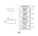
對此,本發明提出一種複檢影像處理方法與複檢系統, 如圖1所示,於一實施例中,複檢系統包括一影像處理裝置100、一照相機110以及一載台120。於一實施例中,影像處理裝置100可由電腦系統實作,通過軟體方法配合硬體實現多種功能模組,但不以此為限。影像處理裝置100包括一檢測資訊取得單元101、一照相機控制單元103、一瑕疵清晰度判斷單元105、一瑕疵影像合成單元107以及一複檢單元109。於其他實施例中,影像處理裝置100的實施方式可依設計需求而變更。To this end, the present invention proposes a re-inspection image processing method and a re-inspection system. As shown in FIG1 , in one embodiment, the re-inspection system includes an
於一實施例中,檢測資訊取得單元101從自動光學檢測系統得到一待檢測物200的一檢測資訊後,照相機控制單元103控制照相機110拍攝放置在載台120上的待檢測物200,以進行瑕疵複檢作業。於一實施例中,待檢測物200具有一瑕疵。於一實施例中,待檢測物200可以是各種工業製品,如印刷電路板、晶圓、積體電路佈局或基材等半導體製品,但不以此為限。於一實施例中,待檢測物200的檢測資訊可以是瑕疵的類別、大小、位置等資訊,但不以此為限。於另一實施例中,待檢測物200的檢測資訊,可以是一檢測影像,由影像處理裝置100影像分析出瑕疵的類別、大小、位置資訊。In one embodiment, after the detection
於一實施例中,瑕疵清晰度判斷單元105自照相機110取得複檢影像並進行影像清晰度判斷,確認出準確對焦的清晰影像。於一實施例中,瑕疵影像合成單元107將不同瑕疵影像區塊的清晰影像進行合成,以取得完整且準確對焦的瑕疵影像。於一實施例中,複檢單元109針對完整且準確對焦的瑕疵影像進行複檢判斷,確認瑕疵的真實性,以完成複檢作業。In one embodiment, the defect
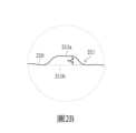
在取得待檢測物200的影像的實施方式之一,可參考圖2A與圖2B所示,利用照相機拍攝具有表面高度落差的待檢測物的實施例示意圖。根據圖2A,於一實施例中,照相機110具有一鏡頭111且待檢測物200具有一表面210。於一實施例中,鏡頭111為一淺景深鏡頭,而待檢測物200的表面210具有一高低落差區域211。照相機110通過鏡頭111拍攝待檢測物200的表面210。於一實施例中,表面210的高低落差區域211具有一高度落差d。In one embodiment of obtaining an image of the object to be detected 200, reference can be made to FIG. 2A and FIG. 2B, which are schematic diagrams of an embodiment of using a camera to shoot an object to be detected having a surface height difference. According to FIG. 2A, in one embodiment, the
當使用鏡頭111以單一焦距拍攝待檢測物200的表面210時,一張影像中會因為表面有高低落差而無法準確對焦在每個部位上,而會有模糊的區域。例如在高低落差區域211中,當準確對焦在高度落差d的一上緣位置211a拍攝一張影像時,這張影像中高度落差d的一下緣位置211b部分可能會是模糊的。因此,為了要取得多個部位都有準確對焦的完整影像,於一實施例中,是控制照相機110在多個對焦位置(Focus Position)對表面210的同一區塊拍攝多張不同焦點深度(Focus Depth)的影像,進而取得清晰的對焦影像。When the
在進行瑕疵複檢時,如圖3所示,為了要取得準確對焦的瑕疵影像,本發明的複檢影像處理方法包括以下步驟:S701 取得一待檢測物的一檢測資訊,並將待檢測物區分為多個子區塊,待檢測物具有一瑕疵;S703 依照檢測資訊,針對具有瑕疵的每一子區塊,取得在多個對焦位置拍攝的多個複檢影像;S705 計算每一複檢影像的邊緣銳度,取得具有最高邊緣銳度的複檢影像;S707 將具有最高邊緣銳度的複檢影像合成;以及 S709 獲得完整且準確對焦的一瑕疵影像。When performing defect re-inspection, as shown in FIG3 , in order to obtain an accurately focused defect image, the re-inspection image processing method of the present invention includes the following steps: S701 obtaining detection information of an object to be inspected, and dividing the object to be inspected into a plurality of sub-blocks, wherein the object to be inspected has a defect; S703 obtaining a plurality of re-inspection images shot at a plurality of focus positions for each sub-block having the defect according to the detection information; S705 calculating the edge sharpness of each re-inspection image, and obtaining a re-inspection image with the highest edge sharpness; S707 synthesizing the re-inspection images with the highest edge sharpness; and S709 obtaining a complete and accurately focused defect image.
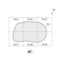
在步驟S701,如圖4所示,將待檢測物200區分多個子區塊的實施例示意圖。先將待檢測物200區分為多個子區塊,其中多個子區塊的全部或一部分涵蓋一瑕疵212,形成多個待測區塊。主要目的之一是將整個待檢測物200區分不同的區塊,而能逐一處理以取得準確對焦的待測區塊。值得一提的是,可依據實際需求決定子區塊的大小,參考的需求例如表面瑕疵的樣式以及瑕疵解析度的要求。於一實施例中,比如,瑕疵212涵蓋的子區塊為編號No.21, No.22, No.23,No.27, No.28與No.29的待測區塊,後續複檢將針對前述六個待測區塊進行。In step S701, as shown in FIG4, a schematic diagram of an embodiment of dividing the object to be tested 200 into a plurality of sub-blocks is provided. The object to be tested 200 is first divided into a plurality of sub-blocks, wherein all or part of the plurality of sub-blocks cover a
接著配合圖1,在步驟S703,當得出涵蓋瑕疵212的多個待測區塊後,複檢系統再通過影像處理裝置100的照相機控制單元103控制照相機110,以固定的節距(Pitch)循序調整照相機110到多個對焦位置拍攝待檢測物200的待測區塊得出多張複檢影像。Next, in conjunction with FIG. 1 , in step S703 , after obtaining multiple test blocks covering the
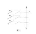
於一實施例中,得出多張複檢影像的實施方式可以再配合圖5所示,對待檢測物200取得多個節距的複檢影像的實施例示意圖。複檢系統循序以一個軸向(於一實施例中為Z軸)調整照相機110以固定的一節距p在多個對焦位置拍攝待檢測物200,特別是針對待檢測物200上的待測區塊位置上取像,得出如圖4的複檢影像401, 403與405,其中複檢影像401, 403與405皆對同一特定待測區塊。值得一提的是,節距p的決定可以依據實際鏡頭景深以及表面瑕疵的高度落差而定,目的是能夠使得瑕疵影像的每個像素都能取得最高邊緣銳度(Edge Acutance)。In one embodiment, the implementation method of obtaining multiple re-inspection images can be combined with the schematic diagram of an embodiment of obtaining re-inspection images of multiple pitches for the object to be inspected 200 as shown in FIG5. The re-inspection system sequentially adjusts the
詳細而言,針對瑕疵212所涵蓋的待測區塊No.21, No.22, No.23,No.27, No.28與No.29,複檢系統先針對待測區塊No.21進行以固定節距p在多個對焦位置拍攝多張複檢影像。完成待測區塊No.21的多張複檢影像拍攝後,再依相同方法,針對待測區塊No.22拍攝以取得待測區塊No.22的多張複檢影像。依照待測區塊的編號順序,分別陸續完成待測區塊No.21, No.22, No.23,No.27, No.28與No.29的複檢影像拍攝作業。Specifically, for the test blocks No.21, No.22, No.23, No.27, No.28 and No.29 covered by the
之後,在步驟S705,在複檢影像處理方法中,通過影像處理裝置100中的瑕疵清晰度判斷單元105,取得特定待測區塊中每張複檢影像區塊的像素灰階值,進而比較出邊緣稅度最高的一張複檢影像,主要是指整體影像的銳度或是解析度(Resolution)。Then, in step S705, in the re-inspection image processing method, the pixel grayscale value of each re-inspection image block in the specific test block is obtained through the defect
於一實施例中,執行邊緣偵測(Edge Detection)的方法,例如可以運用拉普拉斯算符(Laplacian Operator)等的數學方法,其他方法還有Sobel、Scharr等,邊緣偵測的方法於本發明中不允以為限,主要目的是取得每張複檢影像的邊緣銳度。所述邊緣銳度指深淺色調邊界的灰階對比度,因為待測區塊中像素值有突然變化的特徵,因此在以多個對焦位置拍攝的多張複檢影像中,可以根據邊緣銳度判斷其中準確對焦的一張複檢影像。In one embodiment, the edge detection method may use a mathematical method such as Laplacian Operator, and other methods include Sobel, Scharr, etc. The edge detection method is not limited in the present invention, and the main purpose is to obtain the edge sharpness of each re-inspected image. The edge sharpness refers to the grayscale contrast of the boundary between dark and light tones. Because the pixel values in the block to be tested have the characteristic of sudden changes, among the multiple re-inspected images taken at multiple focus positions, the one with accurate focus can be determined based on the edge sharpness.
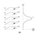
比如,再配合圖6所示,從多個複檢影像中得出最清晰影像的實施例示意圖,其中顯示前述以固定的節距p在多個對焦位置拍攝待檢測物得出的多張複檢影像(501, 502, 503, 504與505),分別是編號n=1的第一複檢影像501、編號n=2的第二複檢影像502、編號n=3的第三複檢影像503、編號n=4的第四複檢影像504,以及編號n=5的第五複檢影像505。For example, as shown in Figure 6, a schematic diagram of an implementation example of obtaining the clearest image from multiple review images shows multiple review images (501, 502, 503, 504 and 505) obtained by photographing the object to be inspected at multiple focus positions with a fixed pitch p, which are respectively the
由於邊緣偵測方法的目的是得到各影像中深淺色調有突然變化的像素特徵,可判斷為邊緣,也就是邊緣銳度高的部分。根據邊緣偵測的實施例之一,針對每張複檢影像運用所述拉普拉斯算符以一次微分演算出每張複檢影像中經過灰階化的像素的邊緣銳度,產生如圖6顯示的二維示意圖,藉此可判斷出特定待測區塊中不同複檢影像的邊緣銳度變化。於一實施例中,顯示第三複檢影像503(n=3)的灰階值經一次微分後得出一峰值50,此峰值50代表第三複檢影像503的具有最高的邊緣銳度。於一實施例中,也可以設定一閥值判斷具有最高邊緣銳度的複檢影像。進一步地,還可以通過拉普拉斯算符進行第二次微分,更進一步確認出具有最高邊緣銳度的複檢影像。Since the purpose of the edge detection method is to obtain the pixel features with sudden changes in light and dark tones in each image, it can be judged as an edge, that is, a portion with high edge sharpness. According to one embodiment of edge detection, the Laplace operator is used for each re-examination image to calculate the edge sharpness of the grayscaled pixels in each re-examination image by a single differentiation, generating a two-dimensional schematic diagram as shown in FIG. 6, thereby determining the edge sharpness changes of different re-examination images in a specific block to be tested. In one embodiment, the grayscale value of the third re-examination image 503 (n=3) is displayed, and a
接著,在步驟S707及步驟S709中,將待測區塊分別具有最高銳度的複檢影像合成。通過影像處理裝置100的瑕疵影像合成單元107組合多個待測區塊的準確對焦複檢影像,最終形成一清晰度最高的瑕疵影像。Next, in step S707 and step S709, the re-inspection images with the highest sharpness of the tested area are synthesized. The defect
當得出涵蓋瑕疵的所有待測區塊中每個複檢影像的邊緣銳度值,再經比對後,針對每個待測區塊中具有最大邊緣銳度的一張影像,組合這些具有最大邊緣銳度的複檢影像,而形成一清晰度最高的瑕疵影像。如圖7所示,經過最佳清晰度挑選以合成得出的最清晰瑕疵影像實施例示意圖,其中示意表示涵蓋瑕疵212的多個待測區塊,分別是編號為No.21, No.22, No.23, No.27, No.28, No.29的待測區塊,並且是經過組合具有最大邊緣銳度的待測區塊所形成清晰度最高的一瑕疵影像60。When the edge sharpness values of each re-inspected image in all the test blocks covering the defect are obtained, after comparison, for an image with the maximum edge sharpness in each test block, these re-inspected images with the maximum edge sharpness are combined to form a defect image with the highest definition. As shown in FIG7 , a schematic diagram of an embodiment of the clearest defect image obtained by synthesizing after the best definition selection is shown, wherein a plurality of test blocks covering the
取得清晰度最高的瑕疵影像60後,最後由影像處理裝置100的複檢單元109確認瑕疵影像60中瑕疵212的真實性後,完成複檢作業。於一實施例中,影像處理裝置100的複檢單元109係可以為透過一般影像分析方法(例如高斯、傅立葉、二值化、影像相減、型態分析)獲得瑕疵212的種類及位置、或是透過機器學習、深度學習等利用類神經網絡進行瑕疵種類的辨識及定位,於本發明中不予以限制。After obtaining the
綜上所述,本發明提出的複檢影像處理方法與複檢系統,能夠有效改善在進行光學複檢時因為採用淺景深鏡頭拍照而造成複檢影像模糊的問題。同時,讓複檢影像內有高度落差的位置都變得清晰,使得整體取像的效果如同增大了鏡頭景深。In summary, the re-inspection image processing method and re-inspection system proposed by the present invention can effectively improve the problem of blurry re-inspection images caused by using a shallow depth of field lens to take photos during optical re-inspection. At the same time, the positions with height differences in the re-inspection image become clear, making the overall imaging effect as if the lens depth of field is increased.
以上所公開的內容僅為本發明的優選可行實施例,並非因此侷限本發明的申請專利範圍,所以凡是運用本發明說明書及圖式內容所做的等效技術變化,均包含於本發明的申請專利範圍內。The contents disclosed above are only preferred feasible embodiments of the present invention and are not intended to limit the scope of the patent application of the present invention. Therefore, all equivalent technical changes made using the contents of the specification and drawings of the present invention are included in the scope of the patent application of the present invention.
100:影像處理裝置 101:檢測資訊取得單元 103:照相機控制單元 105:瑕疵清晰度判斷單元 107:瑕疵影像合成單元 109:複檢單元 110:照相機 111:鏡頭 120:載台 200:待檢測物 210:待檢測物表面 211:高低落差區域 211a:上緣位置 211b:下緣位置 d:高低落差 212:瑕疵 401,403,405:複檢影像 p:節距 501:第一複檢影像 502:第二複檢影像 503:第三複檢影像 504:第四複檢影像 505:第五複檢影像 50:峰值 60:瑕疵影像 步驟S701~S709:複檢影像處理流程100: Image processing device101: Detection information acquisition unit103: Camera control unit105: Defect clarity judgment unit107: Defect image synthesis unit109: Re-inspection unit110: Camera111: Lens120: Stage200: Object to be inspected210: Surface of object to be inspected211:
圖1顯示本發明複檢系統的一實施例示意圖。FIG1 is a schematic diagram showing an embodiment of the review system of the present invention.
圖2A顯示本發明複檢系統利用照相機拍攝待檢測物的一實施例示意圖。FIG. 2A is a schematic diagram showing an embodiment of the re-testing system of the present invention using a camera to photograph an object to be tested.
圖2B顯示圖2B中IIB區塊的放大示意圖。FIG. 2B is an enlarged schematic diagram of block IIB in FIG. 2B .
圖3顯示本發明複檢影像處理方法的一實施例流程圖。FIG. 3 is a flow chart showing an embodiment of the re-inspection image processing method of the present invention.
圖4顯示本發明複檢影像處理方法將待檢測物區分為多個子區塊的一實施例示意圖。FIG. 4 is a schematic diagram showing an embodiment of the re-inspection image processing method of the present invention for dividing the object to be inspected into a plurality of sub-blocks.
圖5顯示本發明複檢影像處理方法對待檢測物取得多個節距的複檢影像的一實施例示意圖。FIG. 5 is a schematic diagram showing an embodiment of the re-inspection image processing method of the present invention for obtaining re-inspection images of multiple pitches for an object to be inspected.
圖6顯示本發明複檢影像處理方法從多個複檢影像中得出最清晰影像的一實施例示意圖。FIG6 is a schematic diagram showing an embodiment of the re-inspection image processing method of the present invention for obtaining the clearest image from a plurality of re-inspection images.
圖7顯示本發明複檢影像處理方法經過最佳清晰度挑選以合成出的最清晰瑕疵影像的一實施例示意圖。FIG. 7 is a schematic diagram showing an embodiment of the method for processing re-inspected images of the present invention, in which the clearest defect image is synthesized after the best definition selection.
401,403,405:複檢影像401,403,405: Recheck images
p:節距p:pitch
Claims (18)
Translated fromChineseApplications Claiming Priority (2)
| Application Number | Priority Date | Filing Date | Title |
|---|---|---|---|
| CN202310033813.XACN118329894A (en) | 2023-01-10 | 2023-01-10 | Re-inspection image processing method and re-inspection system |
| CN202310033813.X | 2023-01-10 |
Publications (2)
| Publication Number | Publication Date |
|---|---|
| TW202429379Atrue TW202429379A (en) | 2024-07-16 |
| TWI893356B TWI893356B (en) | 2025-08-11 |
Family
ID=
Also Published As
| Publication number | Publication date |
|---|---|
| CN118329894A (en) | 2024-07-12 |
Similar Documents
| Publication | Publication Date | Title |
|---|---|---|
| JP2005315596A (en) | Image inspection method and apparatus | |
| WO2020246366A1 (en) | Substrate inspection device, substrate inspection system, and substrate inspection method | |
| JP7151873B2 (en) | inspection equipment | |
| JPWO2009031612A1 (en) | Observation apparatus and observation method, and inspection apparatus and inspection method | |
| JP7157580B2 (en) | Board inspection method and board inspection apparatus | |
| JP2004354250A (en) | Defect inspection device | |
| JP5716278B2 (en) | Foreign object detection device and foreign object detection method | |
| CN118329894A (en) | Re-inspection image processing method and re-inspection system | |
| JP2009139133A (en) | Defect detection method and defect detection apparatus | |
| CN114286078B (en) | Camera module lens appearance inspection method and equipment | |
| TWI893356B (en) | Method for processing review images and review system | |
| TWI718747B (en) | Method for improving the sharpness of an image | |
| JP5544894B2 (en) | Wafer inspection apparatus and wafer inspection method | |
| JP2005315792A (en) | Defect inspecting/classifying apparatus | |
| WO2006006525A1 (en) | Image processing device and method | |
| JP2009192358A (en) | Defect inspection equipment | |
| JP2002175520A (en) | Defect detection device, defect detection method, and recording medium for recording defect detection program on substrate surface | |
| JP5239275B2 (en) | Defect detection method and defect detection apparatus | |
| KR102858521B1 (en) | Detection Device for Surface Defects of Material | |
| WO2018146887A1 (en) | External-appearance examination device | |
| JP7068897B2 (en) | Inspection equipment and inspection method | |
| CN112710662A (en) | Generation method and device, generation system and storage medium | |
| JP7285988B2 (en) | Inspection device and inspection method | |
| KR100710703B1 (en) | Semiconductor lead frame plating line width measurement inspection device and method | |
| JPH0735699A (en) | Method and apparatus for detecting surface defect |