TW202425048A - Substrate processing system and substrate processing method - Google Patents
Substrate processing system and substrate processing methodDownload PDFInfo
- Publication number
- TW202425048A TW202425048ATW112128725ATW112128725ATW202425048ATW 202425048 ATW202425048 ATW 202425048ATW 112128725 ATW112128725 ATW 112128725ATW 112128725 ATW112128725 ATW 112128725ATW 202425048 ATW202425048 ATW 202425048A
- Authority
- TW
- Taiwan
- Prior art keywords
- gas
- substrate
- processing
- plasma
- chamber
- Prior art date
Links
- 238000012545processingMethods0.000titleclaimsabstractdescription283
- 239000000758substrateSubstances0.000titleclaimsabstractdescription241
- 238000003672processing methodMethods0.000titleclaimsabstractdescription12
- 238000010494dissociation reactionMethods0.000claimsdescription101
- 230000005593dissociationsEffects0.000claimsdescription100
- 238000000034methodMethods0.000claimsdescription64
- 230000008569processEffects0.000claimsdescription61
- 238000005530etchingMethods0.000claimsdescription34
- 238000005259measurementMethods0.000claimsdescription23
- 238000006243chemical reactionMethods0.000claimsdescription18
- 238000009825accumulationMethods0.000claimsdescription12
- 239000007795chemical reaction productSubstances0.000claimsdescription11
- NBVXSUQYWXRMNV-UHFFFAOYSA-NfluoromethaneChemical compoundFCNBVXSUQYWXRMNV-UHFFFAOYSA-N0.000claimsdescription3
- 206010013470Dissociative statesDiseases0.000abstract3
- 239000007789gasSubstances0.000description293
- 238000009832plasma treatmentMethods0.000description35
- 239000012634fragmentSubstances0.000description28
- 239000000203mixtureSubstances0.000description27
- 150000002500ionsChemical class0.000description12
- 239000013589supplementSubstances0.000description9
- 239000000919ceramicSubstances0.000description8
- 238000012544monitoring processMethods0.000description8
- 238000004891communicationMethods0.000description7
- 230000001276controlling effectEffects0.000description7
- 238000010586diagramMethods0.000description7
- 230000008021depositionEffects0.000description6
- 230000006870functionEffects0.000description6
- 238000009792diffusion processMethods0.000description4
- 230000001105regulatory effectEffects0.000description4
- 230000032258transportEffects0.000description4
- 230000015572biosynthetic processEffects0.000description3
- 238000000354decomposition reactionMethods0.000description3
- 238000001514detection methodMethods0.000description3
- 238000001819mass spectrumMethods0.000description3
- 238000001020plasma etchingMethods0.000description3
- 230000002250progressing effectEffects0.000description3
- 230000035945sensitivityEffects0.000description3
- 238000012546transferMethods0.000description3
- UOACKFBJUYNSLK-XRKIENNPSA-NEstradiol CypionateChemical compoundO([C@H]1CC[C@H]2[C@H]3[C@@H](C4=CC=C(O)C=C4CC3)CC[C@@]21C)C(=O)CCC1CCCC1UOACKFBJUYNSLK-XRKIENNPSA-N0.000description2
- 101000827703Homo sapiens Polyphosphoinositide phosphataseProteins0.000description2
- 102100023591Polyphosphoinositide phosphataseHuman genes0.000description2
- 230000008878couplingEffects0.000description2
- 238000010168coupling processMethods0.000description2
- 238000005859coupling reactionMethods0.000description2
- 230000007423decreaseEffects0.000description2
- 230000003247decreasing effectEffects0.000description2
- 238000004868gas analysisMethods0.000description2
- 239000011810insulating materialSubstances0.000description2
- 238000005070samplingMethods0.000description2
- BSYNRYMUTXBXSQ-UHFFFAOYSA-NAspirinChemical compoundCC(=O)OC1=CC=CC=C1C(O)=OBSYNRYMUTXBXSQ-UHFFFAOYSA-N0.000description1
- 101001121408Homo sapiens L-amino-acid oxidaseProteins0.000description1
- 102100026388L-amino-acid oxidaseHuman genes0.000description1
- 101100233916Saccharomyces cerevisiae (strain ATCC 204508 / S288c) KAR5 geneProteins0.000description1
- 230000008901benefitEffects0.000description1
- 238000005513bias potentialMethods0.000description1
- 239000012267brineSubstances0.000description1
- 239000004020conductorSubstances0.000description1
- 230000000694effectsEffects0.000description1
- 238000002474experimental methodMethods0.000description1
- 239000013529heat transfer fluidSubstances0.000description1
- 238000009616inductively coupled plasmaMethods0.000description1
- 238000002347injectionMethods0.000description1
- 239000007924injectionSubstances0.000description1
- 238000009413insulationMethods0.000description1
- 238000005040ion trapMethods0.000description1
- 238000012986modificationMethods0.000description1
- 230000004048modificationEffects0.000description1
- 238000004886process controlMethods0.000description1
- 238000000926separation methodMethods0.000description1
- HPALAKNZSZLMCH-UHFFFAOYSA-Msodium;chloride;hydrateChemical compoundO.[Na+].[Cl-]HPALAKNZSZLMCH-UHFFFAOYSA-M0.000description1
- 239000007787solidSubstances0.000description1
Images


Classifications
- H—ELECTRICITY
- H01—ELECTRIC ELEMENTS
- H01L—SEMICONDUCTOR DEVICES NOT COVERED BY CLASS H10
- H01L21/00—Processes or apparatus adapted for the manufacture or treatment of semiconductor or solid state devices or of parts thereof
- H01L21/02—Manufacture or treatment of semiconductor devices or of parts thereof
- H01L21/04—Manufacture or treatment of semiconductor devices or of parts thereof the devices having potential barriers, e.g. a PN junction, depletion layer or carrier concentration layer
- H01L21/18—Manufacture or treatment of semiconductor devices or of parts thereof the devices having potential barriers, e.g. a PN junction, depletion layer or carrier concentration layer the devices having semiconductor bodies comprising elements of Group IV of the Periodic Table or AIIIBV compounds with or without impurities, e.g. doping materials
- H01L21/30—Treatment of semiconductor bodies using processes or apparatus not provided for in groups H01L21/20 - H01L21/26
- H01L21/302—Treatment of semiconductor bodies using processes or apparatus not provided for in groups H01L21/20 - H01L21/26 to change their surface-physical characteristics or shape, e.g. etching, polishing, cutting
- H01L21/306—Chemical or electrical treatment, e.g. electrolytic etching
- H01L21/3065—Plasma etching; Reactive-ion etching
- H—ELECTRICITY
- H01—ELECTRIC ELEMENTS
- H01L—SEMICONDUCTOR DEVICES NOT COVERED BY CLASS H10
- H01L21/00—Processes or apparatus adapted for the manufacture or treatment of semiconductor or solid state devices or of parts thereof
- H01L21/02—Manufacture or treatment of semiconductor devices or of parts thereof
- H01L21/04—Manufacture or treatment of semiconductor devices or of parts thereof the devices having potential barriers, e.g. a PN junction, depletion layer or carrier concentration layer
- H01L21/18—Manufacture or treatment of semiconductor devices or of parts thereof the devices having potential barriers, e.g. a PN junction, depletion layer or carrier concentration layer the devices having semiconductor bodies comprising elements of Group IV of the Periodic Table or AIIIBV compounds with or without impurities, e.g. doping materials
- H01L21/30—Treatment of semiconductor bodies using processes or apparatus not provided for in groups H01L21/20 - H01L21/26
- H01L21/31—Treatment of semiconductor bodies using processes or apparatus not provided for in groups H01L21/20 - H01L21/26 to form insulating layers thereon, e.g. for masking or by using photolithographic techniques; After treatment of these layers; Selection of materials for these layers
- H—ELECTRICITY
- H05—ELECTRIC TECHNIQUES NOT OTHERWISE PROVIDED FOR
- H05H—PLASMA TECHNIQUE; PRODUCTION OF ACCELERATED ELECTRICALLY-CHARGED PARTICLES OR OF NEUTRONS; PRODUCTION OR ACCELERATION OF NEUTRAL MOLECULAR OR ATOMIC BEAMS
- H05H1/00—Generating plasma; Handling plasma
- H—ELECTRICITY
- H05—ELECTRIC TECHNIQUES NOT OTHERWISE PROVIDED FOR
- H05H—PLASMA TECHNIQUE; PRODUCTION OF ACCELERATED ELECTRICALLY-CHARGED PARTICLES OR OF NEUTRONS; PRODUCTION OR ACCELERATION OF NEUTRAL MOLECULAR OR ATOMIC BEAMS
- H05H1/00—Generating plasma; Handling plasma
- H05H1/24—Generating plasma
- H05H1/46—Generating plasma using applied electromagnetic fields, e.g. high frequency or microwave energy
Landscapes
- Engineering & Computer Science (AREA)
- Physics & Mathematics (AREA)
- Plasma & Fusion (AREA)
- Microelectronics & Electronic Packaging (AREA)
- Manufacturing & Machinery (AREA)
- Computer Hardware Design (AREA)
- General Physics & Mathematics (AREA)
- Power Engineering (AREA)
- Condensed Matter Physics & Semiconductors (AREA)
- Spectroscopy & Molecular Physics (AREA)
- Electromagnetism (AREA)
- Chemical Vapour Deposition (AREA)
- Drying Of Semiconductors (AREA)
Abstract
Description
Translated fromChinese本揭示有關基板處理系統及基板處理方法。The present disclosure relates to a substrate processing system and a substrate processing method.
於專利文獻1,已有人開示了一種基板處理系統,其具備透過氣體採取配管及閥採取並分析腔室內氣體的氣體分析裝置。已有人開示一種使用例如四極桿質量分析器等,來作為氣體分析裝置。 [先前技術文獻]In
[專利文獻] [專利文獻1]日本特開2010-27787號公報[Patent Document][Patent Document 1] Japanese Patent Application Publication No. 2010-27787
[發明所欲解決之問題] 本揭示於一態樣中,提供一種以高精度控制電漿處理之基板處理系統及基板處理方法。 [解決問題之技術手段][Problem to be solved by the invention]In one aspect, the present invention provides a substrate processing system and a substrate processing method for controlling plasma processing with high precision.[Technical means for solving the problem]
為解決上述課題,根據一態樣,提供一種基板處理系統,具備:腔室;基板支持部,設於該腔室內;氣體供給部,以對該腔室內供給氣體的方式構成;RF電源,以為了在該腔室內從該氣體產生電漿而供給RF電力的方式構成;氣體量測部,以量測該電漿中該氣體的解離狀態的方式構成;及控制部;該控制部,係控制成依照設定好的基板的處理條件於該腔室內開始載置在該基板支持部的基板的處理,控制成在該基板的該處理間,從該氣體量測部取得該氣體的解離狀態,控制成基於該氣體的解離狀態,調整該基板或在該基板之後接受處理的基板的處理條件。 [發明功效]To solve the above-mentioned problem, according to one aspect, a substrate processing system is provided, comprising: a chamber; a substrate support part, which is arranged in the chamber; a gas supply part, which is configured to supply gas into the chamber; an RF power source, which is configured to supply RF power in order to generate plasma from the gas in the chamber; a gas measuring part, which is configured to measure the dissociation state of the gas in the plasma; and a control part; the control part is controlled to start processing of the substrate mounted on the substrate support part in the chamber according to the set processing conditions of the substrate, to obtain the dissociation state of the gas from the gas measuring part during the processing of the substrate, and to adjust the processing conditions of the substrate or a substrate to be processed after the substrate based on the dissociation state of the gas.[Effect of the invention]
根據一態樣,可提供以高精度控制電漿處理之基板處理系統及基板處理方法。According to one aspect, a substrate processing system and a substrate processing method for controlling plasma processing with high precision can be provided.
以下,參照圖式,針對各種示意性的實施態樣進行詳細說明。另外,對各圖式中相同或相似的部分賦予相同的符號。In the following, various exemplary embodiments are described in detail with reference to the drawings. In addition, the same symbols are given to the same or similar parts in each drawing.
針對電漿處理系統(基板處理系統),使用圖1進行說明。圖1係電漿處理系統之一例的構成圖。The plasma processing system (substrate processing system) will be described with reference to Fig. 1. Fig. 1 is a configuration diagram of an example of the plasma processing system.
圖1為用以說明電漿處理系統的構成例的圖。一實施態樣中,電漿處理系統包含電漿處理裝置1及控制部2。電漿處理系統為基板處理系統之一例,而電漿處理裝置1為基板處理裝置之一例。電漿處理裝置1包含:電漿處理腔室(腔室)10、基板支持部11及電漿產生部12。電漿處理腔室10具有電漿處理空間。然後,電漿處理腔室10具有:至少1個氣體供給口,其係用以將至少1個處理氣體供給至電漿處理空間;及至少1個氣體排出口,其係用以從電漿處理空間排出氣體。氣體供給口係與後述之氣體供給部20連接,氣體排出口係與後述之排氣系統40連接。基板支持部11被配置在電漿處理空間內,具有用以支持基板的基板支持面。FIG1 is a diagram for illustrating an example of a configuration of a plasma processing system. In one embodiment, the plasma processing system includes a
電漿產生部12係以從被供給到電漿處理空間內之至少1個處理氣體產生電漿的方式構成。在電漿處理空間中所形成的電漿亦可為電容式耦合電漿(CCP; Capacitively Coupled Plasma)、感應耦合電漿(ICP;Inductively Coupled Plasma)、電子迴旋共振電漿(ECR;Electron-Cyclotron-resonance plasma)、螺旋波電漿(HWP:Helicon Wave Plasma)或者表面波電漿(SWP:Surface Wave Plasma)等。又,使用包含AC(Alternating Current;交流)電漿產生部及DC(Direct Current;直流)電漿產生部之各種類型的電漿產生部皆可。一實施態樣中,用於AC電漿產生部之AC信號(AC電力)具有100kHz~10GHz範圍內的頻率。因此,AC信號包含RF(Radio Frequency;射頻)信號及微波信號。一實施態樣中,RF信號具有100kHz~150MHz範圍內的頻率。The
控制部2係處理使電漿處理裝置1執行本揭示中所述之各種工序的電腦可執行之命令。控制部2可構成為將電漿處理裝置1之各要件控制成執行在此所述之各種工序。一實施態樣中,電漿處理裝置1亦可包含控制部2的一部分或全部。控制部2亦可包含處理部2a1、儲存部2a2及通信介面2a3。控制部2可利用例如電腦2a來實現。處理部2a1可構成為藉由自儲存部2a2讀取程式,並執行所讀取的程式來進行各種控制動作。該程式亦可預先被存儲在儲存部2a2,也可在需要時,經由媒體而取得。所取得的程式被存儲在儲存部2a2,藉由處理部2a1自儲存部2a2讀取而執行。媒體亦可為電腦2a可讀取之各種儲存媒體,也可為與通信介面2a3連接之通信線路。處理部2a1亦可為CPU(Central Processing Unit;中央處理單元)。儲存部2a2亦可包含RAM(Random Access Memory;隨機存取記憶體)、ROM(Read Only Memory;唯讀記憶體)、HDD(Hard Disk Drive;硬式磁碟機)、SSD(Solid State Drive;固態硬碟)或該等的組合。通信介面2a3亦可透過LAN(Local Area Network;區域網路)等通信線路而在電漿處理裝置1間進行通信。The
以下,針對作為電漿處理裝置1的一例之電容耦合式電漿處理裝置1的構成例進行說明。圖2係電容耦合式電漿處理裝置1的一例之構成圖。圖3係電漿處理裝置1之其他一例的構成圖。Hereinafter, a configuration example of a capacitive coupling type
電容耦合式電漿處理裝置1係包含:電漿處理腔室10;氣體供給部20;電源30及排氣系統40。又,電漿處理裝置1包含基板支持部11及氣體導入部。氣體導入部係以將至少1種處理氣體導入至電漿處理腔室10內的方式構成。氣體導入部包含噴淋頭(shower head)13。基板支持部11配置在電漿處理腔室10內。噴淋頭13配置在基板支持部11的上方。一實施態樣中,噴淋頭13構成電漿處理腔室10的頂部(ceiling)的至少一部分。電漿處理腔室10具有以噴淋頭13、電漿處理腔室10的側壁10a及基板支持部11所界定的電漿處理空間10s。電漿處理腔室10係接地。噴淋頭13及基板支持部11係與電漿處理腔室10的殼體電性絕緣。The capacitively coupled
基板支持部11包含本體部111及環組件112。本體部111具有:中央區域111a,其用以支持基板W;及環狀區域111b,其用以支持環組件112。晶圓係基板W的一例。本體部111的環狀區域111b在俯視下圍繞著本體部111的中央區域111a。基板W配置在本體部111的中央區域111a上,環組件112係以圍繞本體部111的中央區域111a上之基板W的方式,配置在本體部111的環狀區域111b上。因此,中央區域111a亦稱為用以支持基板W的基板支持面,環狀區域111b也稱為用以支持環組件112的環支持面。The
一實施態樣中,本體部111包含基台1110及靜電卡盤1111。基台1110包含導電性構件。基台1110的導電性構件可作為下部電極而發揮功能。靜電卡盤1111配置在基台1110上。靜電卡盤1111包含配置於陶瓷構件1111a及陶瓷構件1111a內之靜電電極1111b。陶瓷構件1111a具有中央區域111a。一實施態樣中,陶瓷構件1111a亦具有環狀區域111b。另外,如環狀靜電卡盤或環狀絕緣構件般之圍繞靜電卡盤1111的其他構件也可具有環狀區域111b。於該情況,環組件112亦可配置於環狀靜電卡盤或環狀絕緣構件上,也可配置於靜電卡盤1111與環狀絕緣構件兩者上。又,與後述的RF電源31及/或DC電源32耦合之至少1個RF/DC電極亦可配置於陶瓷構件1111a內。於該情況,至少1個RF/DC電極下部電極作為下部電極而發揮功能。於後述的偏壓RF信號及/或DC信號被供給到至少1個RF/DC電極的情況,RF/DC電極亦稱作偏壓電極。又,基台1110的導電性構件與至少1個RF/DC電極亦可作為複數個下部電極而發揮功能。且,靜電電極1111b亦可作為下部電極而發揮功能。因此,基板支持部11包含至少1個下部電極。In one embodiment, the main body 111 includes a base 1110 and an electrostatic chuck 1111. The base 1110 includes a conductive member. The conductive member of the base 1110 can function as a lower electrode. The electrostatic chuck 1111 is disposed on the base 1110. The electrostatic chuck 1111 includes a ceramic member 1111a and an electrostatic electrode 1111b disposed in the ceramic member 1111a. The ceramic member 1111a has a central area 111a. In one embodiment, the ceramic member 1111a also has an annular area 111b. In addition, other components surrounding the electrostatic chuck 1111, such as an annular electrostatic chuck or an annular insulating member, may also have an annular region 111b. In this case, the annular assembly 112 may also be arranged on the annular electrostatic chuck or the annular insulating member, or may be arranged on both the electrostatic chuck 1111 and the annular insulating member. In addition, at least one RF/DC electrode coupled to the
環組件112包含1或複數個環狀構件。一實施態樣中,1或複數個環狀構件包含1或複數個邊緣環與至少1個覆蓋環。邊緣環係以導電性材料或絕緣材料形成,覆蓋環係以絕緣材料形成。The ring assembly 112 includes one or more ring-shaped components. In one embodiment, the one or more ring-shaped components include one or more edge rings and at least one cover ring. The edge ring is formed of a conductive material or an insulating material, and the cover ring is formed of an insulating material.
又,基板支持部11亦可包含溫控模組,其係以將靜電卡盤1111、環組件112及基板中至少1者調節成目標溫度之方式構成。溫控模組亦可包含加熱器、傳熱介質、流路1110a或該等的組合。於流路1110a流通有鹵水(Brine)或氣體這樣的傳熱流體。一實施態樣中,流路1110a形成於基台1110內,且1或複數個加熱器被配置於靜電卡盤1111的陶瓷構件1111a內。又,基板支持部11亦可包含傳熱氣體供給部,該傳熱氣體供給部係以將傳熱氣體供給到基板W的背面與中央區域111a之間的間隙之方式構成。Furthermore, the
噴淋頭13係以將來自氣體供給部20的至少1種處理氣體導入到電漿處理空間10s內的方式構成。噴淋頭13具有至少1個氣體供給口13a、至少1個氣體擴散室13b及複數個氣體導入口13c。被供給到氣體供給口13a的處理氣體係通過氣體擴散室13b而從複數個氣體導入口13c被導入到電漿處理空間10s內。又,噴淋頭13包含至少1個上部電極。再者,氣體導入部除了噴淋頭13之外,也可包含1或複數個側部氣體注入部(SGI:Side Gas Injector),其被安裝在形成於側壁10a之1或複數個開口部。The shower head 13 is configured to introduce at least one processing gas from the
氣體供給部20亦可包含至少1個氣體源21及至少1個流量控制器22。一實施態樣中,氣體供給部20構成為將至少1種處理氣體,從分別對應的氣體源21經由分別對應的流量控制器22而供給到噴淋頭13。各流量控制器22例如可包含質量流量控制器或壓力控制式的流量控制器。再者,氣體供給部20可包含使至少1種處理氣體的流量調變或脈衝化之至少1個流量調變裝置。The
電源30包含經由至少1個阻抗匹配電路而與電漿處理腔室10耦合的RF電源31。RF電源31係構成為將至少1個RF信號(RF電力)供給到至少1個下部電極及/或至少1個上部電極。藉此,從被供給到電漿處理空間10s之至少1種處理氣體形成電漿。因此,RF電源31可作為電漿產生部12的至少一部分而發揮功能。又,可藉由將偏壓RF信號供給到至少1個下部電極,而於基板W產生偏壓電位,將已形成的電漿中的離子成分引入到基板W。The power source 30 includes an
一實施態樣中,RF電源31包含第一RF產生部31a及第二RF產生部31b。第一RF產生部31a構成為,經由至少1個阻抗匹配電路而與至少1個下部電極及/或至少1個上部電極耦合,產生電漿產生用的源RF信號(源RF電力)。一實施態樣中,源RF信號具有10MHz~150MHz的範圍內之頻率。一實施態樣中,第一RF產生部31a亦可構成為產生具有不同頻率之複數個源RF信號。所產生之1或複數個源RF信號係供給到至少1個下部電極及/或至少1個上部電極。In one embodiment, the
第二RF產生部31b構成為,經由至少1個阻抗匹配電路而與至少1個下部電極耦合,產生偏壓RF信號(偏壓RF電力)。偏壓RF信號的頻率亦可與源RF信號的頻率相同,也可與其不同。一實施態樣中,偏壓RF信號具有比源RF信號的頻率還低的頻率。一實施態樣中,偏壓RF信號具有100kHz~60MHz範圍內的頻率。一實施態樣中,第二RF產生部31b也可構成為產生具有不同頻率之複數個偏壓RF信號。所產生之1或複數個偏壓RF信號係供給到至少1個下部電極。又,在各種實施態樣中,源RF信號及偏壓RF信號中至少1者可被脈衝化。The second RF generating section 31b is configured to couple with at least one lower electrode via at least one impedance matching circuit to generate a bias RF signal (bias RF power). The frequency of the bias RF signal may be the same as or different from the frequency of the source RF signal. In one embodiment, the bias RF signal has a frequency lower than the frequency of the source RF signal. In one embodiment, the bias RF signal has a frequency in the range of 100kHz to 60MHz. In one embodiment, the second RF generating section 31b may also be configured to generate a plurality of bias RF signals having different frequencies. The generated one or more bias RF signals are supplied to at least one lower electrode. Furthermore, in various implementations, at least one of the source RF signal and the bias RF signal may be pulsed.
又,電源30亦可包含與電漿處理腔室10耦合的DC電源32。DC電源32包含第一DC產生部32a及第二DC產生部32b。一實施態樣中,第一DC產生部32a構成為與至少1個下部電極連接,並產生第一DC信號。所產生之第一DC信號係被施加到至少1個下部電極。一實施態樣中,第二DC產生部32b構成為與至少1個上部電極連接,並產生第二DC信號。所產生之第二DC信號係被施加到至少1個上部電極。In addition, the power supply 30 may also include a DC power supply 32 coupled to the
在各種實施態樣中,亦可將第一及第二DC信號中至少1者脈衝化。於該情況,電壓脈衝波的時序係被施加到至少1個下部電極及/或至少1個上部電極。電壓脈衝波亦可具有矩形、梯形、三角形或該等的組合之脈衝波波形。一實施態樣中,用以從DC信號產生電壓脈衝波的時序之波形產生部係連接於第一DC產生部32a與至少1個下部電極間。因此,第一DC產生部32a及波形產生部構成電壓脈衝波產生部。於第二DC產生部32b及波形產生部構成電壓脈衝波產生部的情況時,電壓脈衝波產生部係與至少1個上部電極連接。電壓脈衝波亦可具有正極性,也可具有負極性。又,電壓脈衝波的時序亦可在1周期內含有1或複數個正極性電壓脈衝波與1或複數個負極性電壓脈衝波。此外,除了RF電源31之外,可以設置第一及第二DC產生部32a, 32b,亦可設置第一DC產生部32a來取代第二RF產生部31b。In various embodiments, at least one of the first and second DC signals may be pulsed. In this case, the timing of the voltage pulse is applied to at least one lower electrode and/or at least one upper electrode. The voltage pulse may also have a rectangular, trapezoidal, triangular or a combination thereof pulse waveform. In one embodiment, a waveform generator for generating the timing of the voltage pulse from the DC signal is connected between the first DC generator 32a and at least one lower electrode. Therefore, the first DC generator 32a and the waveform generator constitute a voltage pulse generator. When the second DC generator 32b and the waveform generator constitute a voltage pulse generator, the voltage pulse generator is connected to at least one upper electrode. The voltage pulse may have a positive polarity or a negative polarity. Furthermore, the timing of the voltage pulse may include one or more positive polarity voltage pulses and one or more negative polarity voltage pulses in one cycle. In addition, the first and second DC generators 32a, 32b may be provided in addition to the
排氣系統40可與設於例如電漿處理腔室10的底部之氣體排出口10e連接。排氣系統40亦可包含壓力調整閥及真空泵。藉由壓力調整閥,可調整電漿處理空間10s內的壓力。真空泵亦可包含渦輪分子泵、乾式泵或該等的組合。The
圖2所示的氣體量測部5(5A)及圖3所示的氣體量測部5(5B)係採取電漿處理腔室10內的氣體並進行量測。如圖2所示,氣體量測部5(5A)具備:氣體量測裝置51;閥52;及配管53。配管53的一端係與被設置在電漿處理腔室10的側壁10a之氣體採取口10b連接。配管53的另一端係與氣體量測裝置51連接。然後,於配管53設有閥52。The gas measuring unit 5 (5A) shown in FIG. 2 and the gas measuring unit 5 (5B) shown in FIG. 3 are used to collect and measure the gas in the
氣體量測裝置51例如可使用四極桿質量分析器(QMS:Quadrupole Mass Analyzer)。四極桿質量分析器係透過將氣體以質量的觀點進行分離,可進行微量成分的量測。且,四極桿質量分析器可量測電漿所造成之氣體的解離。The gas measuring device 51 may be, for example, a quadrupole mass analyzer (QMS). The quadrupole mass analyzer can measure trace components by separating the gas from the perspective of mass. In addition, the quadrupole mass analyzer can measure the dissociation of the gas caused by plasma.
四極桿質量分析器具有離子源部、質量分析部、檢測部。離子源部具備燈絲與燈絲電源。燈絲電源對燈絲施加電壓。被施壓電壓而成為高溫的燈絲係釋放出熱電子。釋放出的熱電子係撞擊氣體,將氣體離子化。質量分析部係對4支電極(四極桿)施加直流或交流的電壓,藉此使既定質量的離子通過。檢測部係檢測通過了質量分析部的離子。The quadrupole mass analyzer has an ion source, a mass analyzer, and a detector. The ion source has a filament and a filament power supply. The filament power supply applies voltage to the filament. The filament, which is heated by the voltage, releases thermal electrons. The released thermal electrons collide with the gas and ionize the gas. The mass analyzer applies a DC or AC voltage to the four electrodes (quadrupole) to allow ions of a predetermined mass to pass through. The detector detects the ions that have passed through the mass analyzer.
閥52將配管53開關的同時,在電漿處理腔室10內的壓力與氣體量測裝置51側的壓力間形成壓力差。When the valve 52 opens and closes the pipe 53, a pressure difference is formed between the pressure in the
又,如圖3所示,氣體量測部5(5B)亦可為差動排氣系統。亦即,氣體量測部5(5B)具備:氣體量測裝置51;閥52;配管53;及排氣系統54。排氣系統54可在例如配管53的閥52與氣體量測裝置51間連接。排氣系統54亦可包含壓力調整閥及真空泵。藉由壓力調整閥,可調整被供給到氣體量測裝置51的氣體的壓力。真空泵亦可包含渦輪分子泵、乾式泵或該等的組合。藉此,電漿處理腔室10內的氣體係透過排氣系統40來進行排氣(參照塗黑箭號)。然後,配管53內的氣體係透過排氣系統54來進行排氣(參照塗黑箭號)。Furthermore, as shown in FIG3 , the gas measuring section 5 (5B) may also be a differential exhaust system. That is, the gas measuring section 5 (5B) includes: a gas measuring device 51; a valve 52; a pipe 53; and an exhaust system 54. The exhaust system 54 may be connected, for example, between the valve 52 of the pipe 53 and the gas measuring device 51. The exhaust system 54 may also include a pressure regulating valve and a vacuum pump. The pressure of the gas supplied to the gas measuring device 51 may be adjusted by the pressure regulating valve. The vacuum pump may also include a turbomolecular pump, a dry pump, or a combination thereof. Thereby, the gas in the
另外,氣體量測裝置51雖以四極桿質量分析器來進行說明,但並不限於此。氣體量測裝置51亦可為例如,殘餘氣體分析器(RGA:Residual Gas Analyzer)、離子阱型質量分析器、飛行時間質譜儀(TOFMS)。In addition, although the gas measuring device 51 is described as a quadrupole mass analyzer, it is not limited thereto and can also be, for example, a residual gas analyzer (RGA), an ion trap mass analyzer, or a time-of-flight mass spectrometer (TOFMS).
接下來,針對電漿處理腔室10內的處理氣體的解離狀態之實驗結果的一例,使用圖4進行說明。圖4係顯示以氣體量測裝置51所量測之處理氣體的解離狀態的圖表的一例。在此,電漿處理腔室10內的壓力20mT(2.7Pa),以Ar氣體800sccm、C4F8氣體20sccm、O2氣體20sccm作為從氣體供給部20導入到電漿處理空間10s之處理氣體,從RF電源31對下部電極及/或上部電極供給RF信號而在電漿處理腔室10內產生該等氣體的電漿,以QMS(氣體量測裝置51)(以下,記載為QMS51。)檢測出該等氣體的解離狀態的組成比率。縱軸顯示以QMS51量測的離子電流比,換言之,顯示C4F8氣體的解離狀態的組成比率。又,(a)係顯示未施加RF信號的狀態的組成比率。(b)係顯示施加了LF信號100W、HF信號700W的狀態。(c)係顯示施加了LF信號400W、HF信號700W的狀態的組成比率。(d)係顯示施加了LF信號700W、HF信號700W的狀態的組成比率。LF信號及HF信號係RF信號的一例,LF信號相當於與下部電極耦合的偏壓RF信號,HF信號相當於與下部電極及/或上部電極耦合的源RF信號。圖4的實驗中,HF信號係供給至上部電極。Next, an example of experimental results of the dissociation state of the process gas in the
C4F8氣體係解離為C(Mass=12)、F(Mass=19)、CF(Mass=31)、CF2(Mass=50)、CF3(Mass=69)、C2F4(Mass=100)、C3F5(Mass=131)等碎片(fragment)。然後,產生從C4F8氣體解離之C與O鍵結的CO(Mass=28)。又,「Mass」係顯示質量數或分子量。QMS51係針對該等的分子量進行量測。又,於以QMS51量測之「Mass=28」的測定結果,除了CO之外,也包含電漿處理腔室10內所含有的N2(Mass=28)。C4 F8 gas is dissociated into fragments such as C (Mass=12), F (Mass=19), CF (Mass=31), CF2 (Mass=50), CF3 (Mass=69), C2 F4 (Mass=100), and C3 F5 (Mass=131). Then, CO (Mass=28) is generated in which C and O are bonded from the dissociated C4 F8 gas. In addition, "Mass" indicates the mass number or molecular weight. QMS51 measures the molecular weights. In addition, the measurement result of "Mass=28" measured by QMS51 includes N2 (Mass=28) contained in the
圖4中,顯示以量測範圍設為由Mass=1至Mass=100為止的QMS51量測的處理氣體的解離狀態的組成比率。如圖4所示,由於電漿處理腔室10內的狀態(圖4的例子中,RF信號的輸出)發生變化,以QMS51檢測的處理氣體的解離狀態的組成比率會變化。Fig. 4 shows the composition ratio of the dissociation state of the process gas measured by the QMS 51 with the measurement range set to Mass = 1 to Mass = 100. As shown in Fig. 4, the composition ratio of the dissociation state of the process gas detected by the QMS 51 changes due to changes in the state in the plasma processing chamber 10 (in the example of Fig. 4, the output of the RF signal).
然而,在使用了CF系的蝕刻氣體的電漿蝕刻製程(電漿處理)中,根據處理氣體的解離狀態,蝕刻對象膜的蝕刻反應、於蝕刻處理時產生之反應產物堆積的堆積(沉積)反應的哪一者處於優位的關係會改變。處理氣體的解離狀態除了RF功率(RF power)、有助於蝕刻之處理氣體的流量(圖4的例子中,C4F8氣體的流量)、處理氣體的流量比(圖4的例子中,C4F8氣體的流量比)、電漿處理腔室10內的壓力、裝置溫度等,在處理配方或製程參數所設定之蝕刻工序中之各式各樣基板的處理條件之外,還根據裝置內的零件的表面狀態等,進行改變。However, in a plasma etching process (plasma treatment) using a CF-based etching gas, the relationship between which is dominant, the etching reaction of the etched film or the accumulation (deposition) reaction of the reaction products generated during the etching process, changes depending on the dissociation state of the processing gas. The dissociation state of the processing gas is changed according to the surface state of the parts in the device, in addition to theprocessing conditions of various substrates in the etching process set by the processing recipe or process parameters, such as RF power, the flow rate of the processing gas that helps etching (in the example of FIG. 4 , the flow rate of C 4F 8gas) , the flow rate ratio of the processing gas (in the example of FIG. 4 , the flow rate ratio of C 4 F 8 gas), the pressure in the
QMS51係透過監測電漿處理中之處理氣體的解離狀態而可監視電漿的狀態。也就是說,將處理氣體的解離狀態以QMS51進行檢測並解析,藉此可掌握電漿處理腔室10內的處理狀態。然後,透過基於QMS51的檢測結果調整處理條件,可控制電漿蝕刻處理。QMS51 can monitor the state of plasma by monitoring the dissociation state of the process gas during the plasma process. In other words, the dissociation state of the process gas is detected and analyzed by QMS51, thereby grasping the process state in the
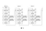
<反饋控制之一例> 使用圖5說明在連續處理複數片基板時,基於在第1基板W的電漿處理中以QMS51量測之處理氣體的解離狀態,調整在第1基板W之後接受處理之第2基板W的處理條件之反饋控制的一例。圖5顯示反饋控制的一例的流程圖。<An example of feedback control>An example of feedback control for adjusting the processing conditions of the second substrate W processed after the first substrate W based on the dissociation state of the processing gas measured by the QMS51 during the plasma processing of the first substrate W when a plurality of substrates are processed continuously is described using FIG5. FIG5 shows a flowchart of an example of feedback control.
如圖5所示,在步驟S11中,控制部2設定對第1片基板W的處理配方等處理條件。處理條件係設定成處理配方及/或製程參數。第1片基板中,處理配方及/或製程參數係例如將在儲存部2a2預先記憶的處理配方及/或製程參數讀出。接下來,步驟S12中,控制部2將第1片基板W搬運到電漿處理腔室10,使基板W被基板支持部11支持。接著,步驟S13中,控制部2係基於基板的處理條件,對基板W施以第1電漿處理。接下來,步驟S14中,控制部2係基於基板的處理條件,對基板W施以第2電漿處理。接著,步驟S15中,控制部2將第1片基板W自電漿處理腔室10搬出。又,在圖5顯示的流程圖的例中,藉由電漿處理裝置1對基板W施以不同的2個電漿處理(第1電漿處理、第2電漿處理)。被施加在基板W的第1電漿處理及第2電漿處理係例如使用了電漿的蝕刻處理。然而,不限於此,亦可藉由電漿處理裝置1對基板W僅進行1個電漿處理(第1電漿處理)。As shown in FIG5, in step S11, the
在此,在對第1片基板W施以第1電漿處理(步驟S13)時,以QMS51量測處理氣體的解離狀態(組成比率)。且,在對第1片基板W施以第2電漿處理(步驟S14)時,以QMS51量測處理氣體的解離狀態(組成比率)。然後,控制部2取得QMS51的測定結果。Here, when the first plasma treatment is applied to the first substrate W (step S13), the dissociation state (composition ratio) of the processing gas is measured by QMS51. And, when the second plasma treatment is applied to the first substrate W (step S14), the dissociation state (composition ratio) of the processing gas is measured by QMS51. Then, the
然後,控制部2係對第2片基板W進行處理條件調整(步驟S21)、基板搬運(步驟S22)、第1電漿處理(步驟S23)、第2電漿處理(步驟S24)、基板搬出(步驟S25)。Then, the
在此,在第2片基板W(於第1片基板W之後接受處理的基板W)中,處理條件調整(步驟S21)係基於對第1片基板W施以第1電漿處理(步驟S13)時之以QMS51量測的處理氣體的解離狀態(組成比率),調整在第1電漿處理(步驟S23)中的處理條件。又,處理條件調整(步驟S21)係基於對第1片基板W施以第2電漿處理(步驟S14)時之以QMS51量測的處理氣體的解離狀態(組成比率),調整在第2電漿處理(步驟S24)中的條件。Here, in the second substrate W (substrate W to be processed after the first substrate W), the processing condition adjustment (step S21) is to adjust the processing condition in the first plasma processing (step S23) based on the dissociation state (composition ratio) of the processing gas measured by the QMS51 when the first plasma processing (step S13) is applied to the first substrate W. Furthermore, the processing condition adjustment (step S21) is to adjust the condition in the second plasma processing (step S24) based on the dissociation state (composition ratio) of the processing gas measured by the QMS51 when the second plasma processing (step S14) is applied to the first substrate W.
藉此,在步驟S23中,控制部2係基於在步驟S21被調整的處理條件,對第2片基板W施以第1電漿處理。然後,在步驟S24中,控制部2係基於在步驟S21被調整的處理條件,對第2片基板W施以第2電漿處理。Thus, in step S23, the
又,在對第2片基板W施以第1電漿處理(步驟S23)時,以QMS51量測處理氣體的解離狀態(組成比率)。且,在對第2片基板W施以第2電漿處理(步驟S24)時,以QMS51量測處理氣體的解離狀態(組成比率)。然後,控制部2取得QMS51的測定結果。Furthermore, when the second substrate W is subjected to the first plasma treatment (step S23), the dissociation state (composition ratio) of the processing gas is measured by QMS51. Furthermore, when the second substrate W is subjected to the second plasma treatment (step S24), the dissociation state (composition ratio) of the processing gas is measured by QMS51. Then, the
以下同樣地,控制部2對第3片基板W(於第2片基板W之後接受處理的基板W)進行處理條件調整(步驟S31)、基板搬運(步驟S32)、第1電漿處理(步驟S33)、第2電漿處理(步驟S34)、基板搬出(步驟S35)。在此,在第3片基板W中,處理條件調整(步驟S31)係基於對第2片基板W施以第1電漿處理(步驟S23)時之以QMS51量測的處理氣體的解離狀態(組成比率),調整在第1電漿處理(步驟S33)中的處理條件。又,處理條件調整(步驟S31)係基於對第2片基板W施以第2電漿處理(步驟S24)時之以QMS51量測的處理氣體的解離狀態(組成比率),調整在第2電漿處理(步驟S34)中的條件。Similarly, the
又,在圖5所示之流程圖中,雖說明了在第1基板W的處理間以QMS51量測處理氣體的解離狀態,並基於已量測的解離狀態對接續第1基板W之後接受處理之第2基板W的處理條件進行調整,但並不限於此。亦可為在第1基板W的處理間以QMS51量測處理氣體的解離狀態,並基於已量測的解離狀態對在第1基板W之後接受處理之基板W的處理條件進行調整的構成。例如,在第1基板W的處理間以QMS51量測處理氣體的解離狀態,並基於已量測的解離狀態對在第1基板W之後接受處理之第2基板W、第3基板W的處理條件進行調整亦可。且,在第1基板W的處理間以QMS51量測處理氣體的解離狀態,並基於已量測的解離狀態對在第1基板W之後接受處理之第3基板W的處理條件進行調整亦可。In addition, in the flowchart shown in FIG5 , although it is explained that the dissociation state of the processing gas is measured by the QMS51 during the processing of the first substrate W, and the processing conditions of the second substrate W to be processed after the first substrate W are adjusted based on the measured dissociation state, the present invention is not limited to this. It is also possible to use a configuration in which the dissociation state of the processing gas is measured by the QMS51 during the processing of the first substrate W, and the processing conditions of the substrate W to be processed after the first substrate W are adjusted based on the measured dissociation state. For example, the dissociation state of the processing gas is measured by the QMS51 during the processing of the first substrate W, and the processing conditions of the second substrate W and the third substrate W to be processed after the first substrate W are adjusted based on the measured dissociation state. Furthermore, during the processing of the first substrate W, the decomposition state of the processing gas may be measured by the QMS 51, and the processing conditions of the third substrate W to be processed after the first substrate W may be adjusted based on the measured decomposition state.
在此,針對處理條件的調整方法的一例,以使用了圖4所示之C4F8氣體等有助於蝕刻之CF系氣體(包含C及F的氟碳化物氣體)的處理條件的情況為例進行說明。Here, an example of a method of adjusting the processing conditions will be described using a case where a CF-based gas (a fluorocarbon gas containing C and F) that facilitates etching, such as C4 F8 gas shown in FIG. 4 , is used as an example.
在第1片基板W中,於第1電漿處理S13及第2電漿處理S14時,以QMS51量測處理氣體的解離狀態(組成比率)。In the first substrate W, during the first plasma treatment S13 and the second plasma treatment S14, the decomposition state (composition ratio) of the processing gas is measured by the QMS51.
在此,針對處理氣體(C4F8)的解離狀態的一例,使用圖6進行說明。圖6係以QMS51量測處理氣體(C4F8)的解離狀態之質譜(mass spectrum)的一例。圖6中,橫軸顯示m/z(質荷比),縱軸顯示相對離子強度。又,圖6中,顯示在電漿非生成時之C4F8的質譜的一例。Here, an example of the dissociation state of the process gas (C4 F8 ) is described using FIG6 . FIG6 is an example of the mass spectrum of the dissociation state of the process gas (C4 F8 ) measured by QMS51. In FIG6 , the horizontal axis shows m/z (mass-to-charge ratio) and the vertical axis shows relative ion intensity. FIG6 also shows an example of the mass spectrum of C4 F8 when plasma is not generated.
如圖6所示,處理氣體(C4F8)的碎片可分成主要碎片610、微量存在碎片620。主要碎片610所檢測出的相對離子強度高,換言之,為組成比率高的碎片。微量存在碎片620所檢測出的相對離子強度小,換言之,為微量地存在的碎片。在圖6顯示的例子中,於C4F8的主要碎片610,包含有CF(Mass=31)、CF2(Mass=50)、CF3(Mass=69)、C2F4(Mass=100)、C3F5(Mass=131)。然後,於電漿產生中,由於碎片因電漿而被細分化,所以小質量數的碎片(例如,C(Mass=12)、F(Mass=19))會增加。因而,於C4F8的主要碎片610,包含有C(Mass=12)、F(Mass=19)。As shown in FIG6 , the fragments of the process gas (C4 F8 ) can be divided into
於是,為了正確地掌握處理氣體(C4F8)的解離狀態,要求QMS51係將從處理氣體假定的碎片的質量範圍全部包含在可量測範圍的規格。在C4F8(Mass=200)中,較佳為使用例如,可量測由Mass=1至Mass=200為止的QMS51。Therefore, in order to accurately grasp the dissociation state of the process gas (C4 F8 ), QMS51 is required to have a specification that includes the mass range of the fragments assumed from the process gas within the measurable range. For example, in C4 F8 (Mass=200), it is preferable to use QMS51 that can measure from Mass=1 to Mass=200.
不過,QMS51並不限於此。QMS51亦可為將組成比率高的主要碎片610之中至少一部分的主要碎片611包含在可量測範圍的規格。在圖6所示的例子中,於一部分的主要碎片611,包含有F(Mass=19)、CF(Mass=31)、CF2(Mass=50)、CF3(Mass=69)。藉此,在電漿處理裝置1中,可量測一部分的主要碎片611之QMS51,例如,可使用可量測由Mass=1至Mass=100為止的QMS51。藉此,可使用可量測範圍比從處理氣體假定的碎片的質量範圍還要狹窄的QMS51,因而可降低成本。However, QMS51 is not limited to this. QMS51 may also be a specification that includes at least a portion of the
具體而言,量測F(Mass=19)、CF(Mass=31)、CF2(Mass=50)、CF3(Mass=69)的比率(氣體組成比率)。在此,比率係由C4F8氣體解離而產生之C(Mass=12)、F(Mass=19)、CO(Mass=28)、CF(Mass=31)、CF2(Mass=50)、CF3(Mass=69)、C2F4(Mass=100)的檢測數量的合計作為母數,而量測作為對象之F(Mass=19)、CF(Mass=31)、CF2(Mass=50)、CF3(Mass=69)個別的比率。又,亦可將不解離的Ar氣體作為基準,量測F(Mass=19)、CF(Mass=31)、CF2(Mass=50)、CF3(Mass=69)各自相對於Ar氣體的比率。Specifically, the ratio (gas composition ratio) of F (Mass=19), CF (Mass=31), CF2 (Mass=50), and CF3 (Mass=69) is measured. Here, the ratio is thesumof the detected numbers of C (Mass=12), F (Mass=19), CO (Mass=28), CF (Mass=31), CF2 (Mass=50), CF3 (Mass=69), and C2 F4 (Mass=100) generated by the dissociation of C 4 F 8 gas as the parent number, and the individual ratios of F (Mass=19), CF (Mass=31), CF2 (Mass=50), and CF3 (Mass=69) as the object are measured. Furthermore, the ratios of F (Mass=19), CF (Mass=31), CF2 (Mass=50), and CF3 (Mass=69) to Ar gas can be measured using the undissociated Ar gas as a standard.
於是,在QMS51的結果中,有助於蝕刻之F及CF中至少一者的比例比目標值(目標的處理狀態值)還多的情況時,判斷CF系氣體為過度解離的狀態。換言之,判斷蝕刻反應為優勢、反應產物的堆積(沉積;deposition)減少(劣勢)。Therefore, in the result of QMS51, when the ratio of at least one of F and CF that contributes to etching is greater than the target value (target processing state value), it is judged that the CF-based gas is in an over-dissociated state. In other words, it is judged that the etching reaction is dominant and the accumulation (deposition) of the reaction product is reduced (disadvantageous).
於該情況,在步驟S21中對第2片基板W設定處理條件時,將CF系氣體的氣體流量(流量比)、CF系氣體的氣體種類(亦包含添加於CF系氣體的添加氣體。)、壓力、HF功率(源RF信號的輸出)、LF功率(偏壓RF信號的輸出)等處理條件的至少一者進行改變。In this case, when setting the processing conditions for the second substrate W in step S21, at least one of the processing conditions such as the gas flow rate (flow ratio) of the CF-based gas, the gas type of the CF-based gas (also including the additional gas added to the CF-based gas), pressure, HF power (output of the source RF signal), and LF power (output of the bias RF signal) is changed.
作為一例,具體而言,將對CF系氣體的解離貢獻較大的HF功率降低,將處理條件進行設定。藉此,在相對於第2片基板W之第1電漿處理S33、第2電漿處理S34中,可抑制CF系氣體的過度解離,令CF系氣體(處理氣體)的解離狀態接近目標值。As an example, specifically, the HF power that contributes more to the dissociation of the CF system gas is reduced and the processing conditions are set. In this way, in the first plasma processing S33 and the second plasma processing S34 with respect to the second substrate W, the excessive dissociation of the CF system gas can be suppressed, and the dissociation state of the CF system gas (processing gas) can be brought close to the target value.
然後,在供給例如CF4等分子量較小的CF系氣體與C4F8等分子量較大的CF系氣體的混合氣體來作為CF系氣體的處理條件中,以使CF4氣體的流量比減少,C4F8的流量比增加的方式改變氣體流量比,將處理條件進行設定。藉此,可令對反應產物的堆積貢獻較大的C4F8的流量比增加。藉此,在相對於第2片基板W之第1電漿處理S33、第2電漿處理S34中,可令CF系氣體(處理氣體)的解離狀態接近目標值。Then, in the treatment condition of supplying a mixed gas of a CF system gas with a smaller molecular weight such as CF4 and a CF system gas with a larger molecular weight such as C4 F8 as the CF system gas, the gas flow ratio is changed so that the flow ratio of CF4 gas is reduced and the flow ratio of C4 F8 is increased, and the treatment condition is set. In this way, the flow ratio of C4 F8 , which contributes more to the accumulation of the reaction product, can be increased. In this way, in the first plasma treatment S33 and the second plasma treatment S34 with respect to the second substrate W, the dissociation state of the CF system gas (treatment gas) can be made close to the target value.
另一方面,於QMS51的結果中,在有助於蝕刻之F及CF中至少一者的比例比目標值還少的情況時,判斷CF系氣體是解離不足的狀態。換言之,判斷蝕刻反應為劣勢、反應產物的堆積(沉積)增加(優勢)。On the other hand, in the result of QMS51, when the ratio of at least one of F and CF that contributes to etching is less than the target value, it is judged that the CF-based gas is in a state of insufficient dissociation. In other words, it is judged that the etching reaction is inferior and the accumulation (deposition) of the reaction product is increased (advantage).
於該情況,在步驟S21中對第2片基板W設定處理條件時,將CF系氣體的氣體流量(流量比)、CF系氣體的氣體種類(添加)、壓力、HF功率、LF功率等處理條件的至少一者進行改變。具體而言,將對CF系氣體的解離貢獻較大的HF功率提升,將處理條件進行調整。藉此,可促進CF系氣體的解離,令CF系氣體(處理氣體)的解離狀態接近目標值。In this case, when setting the processing conditions for the second substrate W in step S21, at least one of the processing conditions such as the gas flow rate (flow ratio) of the CF-based gas, the gas type (addition) of the CF-based gas, the pressure, the HF power, and the LF power is changed. Specifically, the HF power that contributes more to the dissociation of the CF-based gas is increased, and the processing conditions are adjusted. In this way, the dissociation of the CF-based gas can be promoted, and the dissociation state of the CF-based gas (processing gas) is close to the target value.
然後,在供給例如,CF4等分子量較小的CF系氣體與C4F6等分子量較大的CF系氣體的混合氣體來作為CF系氣體的處理條件中,以使CF4氣體的流量比增加,C4F6的流量比降低的方式改變氣體流量比,將處理條件進行設定。藉此,在相對於第2片基板W之第1電漿處理S33、第2電漿處理S34中,可令CF系氣體(處理氣體)的解離狀態接近目標值。Then, in the process condition of supplying, for example, a mixed gas of a CF system gas with a smaller molecular weight such as CF4 and a CF system gas with a larger molecular weight such as C4 F6 as the CF system gas, the gas flow ratio is changed so that the flow ratio of CF4 gas is increased and the flow ratio of C4 F6 is decreased, and the process condition is set. Thereby, in the first plasma process S33 and the second plasma process S34 with respect to the second substrate W, the dissociation state of the CF system gas (processing gas) can be made close to the target value.
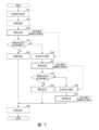
<反饋控制之其他例> 接下來,將在基板W的電漿處理中經以QMS51量測的處理氣體的解離狀態解析,並將即時(real time)調整在該電漿處理的處理條件之控制的一例使用圖7進行說明。圖7係顯示反饋控制之其他一例的流程圖。<Other examples of feedback control>Next, an example of controlling the plasma treatment of substrate W by analyzing the dissociation state of the processing gas measured by QMS51 and adjusting the processing conditions of the plasma treatment in real time will be described using FIG. 7. FIG. 7 is a flowchart showing another example of feedback control.
如圖7所示,在步驟S51中,控制部2設定對基板W的處理條件。於是,處理條件係讀取預先儲存在例如儲存部2a2的處理配方及/或製程參數。接下來,在步驟S52中,控制部2將基板W搬運到電漿處理腔室10,使基板支持部11支持基板W。然後,在步驟S53中,控制部2係根據處理條件,對基板W施以電漿蝕刻處理。As shown in FIG. 7 , in step S51, the
於是,對基板W施以電漿處理(步驟S53)時,以QMS51量測處理氣體的解離狀態(組成比率)。然後,控制部2取得QMS51的測定結果。Then, when the plasma treatment is applied to the substrate W (step S53), the dissociation state (composition ratio) of the processing gas is measured by QMS51. Then, the
然後,在步驟S54中,控制部2判定已量測的解離狀態是否在既定範圍內。已量測的解離狀態在既定範圍內的情況(S54・是),控制部2係持續電漿處理至既定的時間為止(步驟S55),對基板W施以電漿處理。Then, in step S54, the
另一方面,已量測的解離狀態不在既定範圍內的情況(S54・否),控制部2係根據對基板W施以電漿處理S53時以QMS51量測的處理氣體的解離狀態(組成比率),調整電漿處理的處理條件(步驟S56)。且,根據已調整的處理條件,對基板W施以電漿處理(步驟S57)。又,相對於基板W,施以電漿處理(步驟S57)時,以QMS51量測處理氣體的解離狀態(組成比率)。然後,控制部2取得QMS51的測定結果。On the other hand, if the measured dissociation state is not within the predetermined range (S54: No), the
然後,在步驟S58中,控制部2判定,已量測的解離狀態是否在既定範圍內。已量測的解離狀態在既定範圍內的情況(S58・是),控制部2係持續電漿處理直到既定時間(步驟S59),對基板W施以電漿處理。Then, in step S58, the
另一方面,已量測的解離狀態不在既定範圍內的情況(S58・否),控制部2係基於對基板W施以電漿處理S53時之以QMS51量測的處理氣體的解離狀態(組成比率),將電漿處理的處理條件進行調整(步驟S60)。然後,根據已調整的處理條件,對基板W施以電漿處理至既定的時間為止(步驟S61)。又,對基板W施以電漿處理(步驟S61)時,以QMS51量測處理氣體的解離狀態(組成比率),於已量測的解離狀態不在既定範圍內的情況,再次調整處理條件亦可。On the other hand, if the measured dissociation state is not within the predetermined range (S58: No), the
當規定的處理時間經過時,控制部2自電漿處理腔室10將基板W搬出(步驟S62)。When the predetermined processing time has elapsed, the
在此,針對處理條件的調整方法的一例,以使用了C4F8等CF系氣體之處理條件的情況為例進行說明。Here, an example of a method of adjusting the processing conditions will be described using a case where a CF-based gas such as C4 F8 is used as an example.
在基板W中,於第1電漿處理S53時,以QMS51檢測處理氣體的組成比率。又,使用圖6並如前述,為了正確地掌握處理氣體(C4F8)的解離狀態,QMS51係較佳為將從處理氣體假定的碎片的質量範圍全部包含在可量測範圍的規格,但並不限於此。QMS51係將一部分的主要碎片611包含在可量測範圍的構成,例如亦可為從Mass=1至Mass=100為止可量測之四極桿質量分析器。In the substrate W, during the first plasma treatment S53, the composition ratio of the process gas is detected by QMS51. In addition, using FIG. 6 and as described above, in order to accurately grasp the dissociation state of the process gas (C4 F8 ), QMS51 is preferably a specification that includes all the mass ranges of the fragments assumed from the process gas within the measurable range, but is not limited to this. QMS51 is a configuration that includes a part of the
具體而言,量測F(Mass=19)、CF(Mass=31)、CF2(Mass=50)、CF3(Mass=69)之比率(氣體組成比率)。在此,比率係以從C4F8氣體解離而產生之C(Mass=12)、F(Mass=19)、CO(Mass=28)、CF(Mass=31)、CF2(Mass=50)、CF3(Mass=69)、C2F4(Mass=100)的檢測數的合計為母數,量測作為對象之F(Mass=19)、CF(Mass=31)、CF2(Mass=50)、CF3(Mass=69)各自的比率。又,亦可將不解離的Ar氣體作為基準,量測F(Mass=19)、CF(Mass=31)、CF2(Mass=50)、CF3(Mass=69)各自相對於Ar氣體的比率。Specifically, the ratio (gas composition ratio) of F (Mass=19), CF (Mass=31), CF2 (Mass=50) , and CF3 (Mass=69) is measured. Here, the ratio is the sum of the number of detections of C (Mass=12 ), F (Mass=19), CO (Mass=28), CF (Mass=31), CF2 (Mass=50), CF3 (Mass=69), and C2 F4 (Mass=100) generated from the dissociation of C 4 F 8 gas, and the ratio of each of the target F (Mass=19), CF (Mass=31), CF2 (Mass=50), and CF3 (Mass=69) is measured. Furthermore, the ratios of F (Mass=19), CF (Mass=31), CF2 (Mass=50), and CF3 (Mass=69) to Ar gas can be measured using the undissociated Ar gas as a standard.
於是,在QMS51的結果中,有助於蝕刻之F及CF中至少一者的比例比目標值還多的情況時,判斷CF系氣體為過度解離的狀態。換言之,判斷蝕刻反應為優勢、反應產物的堆積(沉積)減少(劣勢)。Therefore, in the result of QMS51, when the ratio of at least one of F and CF, which contribute to etching, is greater than the target value, it is judged that the CF-based gas is in an over-dissociated state. In other words, it is judged that the etching reaction is dominant and the accumulation (deposition) of the reaction product is reduced (disadvantageous).
於該情況,將在電漿處理S57中CF系氣體的氣體流量(流量比)、CF系氣體的氣體種(亦包含添加於CF系氣體的添加氣體。)、壓力、HF功率(源RF信號的輸出)、LF功率(偏壓RF信號的輸出)等處理條件的至少一者進行改變。In this case, at least one of the processing conditions such as the gas flow rate (flow ratio) of the CF-based gas, the gas species of the CF-based gas (including the additional gas added to the CF-based gas), the pressure, the HF power (output of the source RF signal), and the LF power (output of the bias RF signal) will be changed in the plasma processing S57.
作為一例,具體而言,將對CF系氣體的解離貢獻較大的HF功率降低,調整電漿處理S57的處理條件。藉此,在電漿處理S57中,可抑制CF系氣體的過度解離,令CF系氣體(處理氣體)的解離狀態接近目標值。Specifically, for example, the HF power that contributes greatly to the dissociation of the CF system gas is reduced to adjust the processing conditions of the plasma processing S57. In this way, in the plasma processing S57, excessive dissociation of the CF system gas can be suppressed and the dissociation state of the CF system gas (processing gas) can be brought close to the target value.
然後,在供給例如,CF4等分子量較小的CF系氣體與C4F8等分子量較大的CF系氣體的混合氣體來作為CF系氣體的處理條件中,以使CF4氣體的流量比減少,C4F8的流量比增加的方式改變氣體流量比,將處理條件進行設定。藉此,可令對沉積貢獻較大的C4F8的流量比增加。藉此,在電漿處理S57中,可令CF系氣體(處理氣體)的解離狀態接近目標值。Then, in the treatment condition of supplying, for example, a mixed gas of a CF system gas with a smaller molecular weight such as CF4 and a CF system gas with a larger molecular weight such as C4 F8 as the CF system gas, the gas flow ratio is changed so that the flow ratio of CF4 gas is reduced and the flow ratio of C4 F8 is increased, and the treatment condition is set. In this way, the flow ratio of C4 F8 , which contributes more to deposition, can be increased. In this way, in the plasma treatment S57, the dissociation state of the CF system gas (treatment gas) can be made close to the target value.
另一方面,在QMS51的結果中,有助於蝕刻之F及CF中至少一者的比例比目標值還少的情況時,判斷CF系氣體為解離不足的狀態。換言之,判斷反應產物的堆積(沉積)增加。On the other hand, in the result of QMS51, when the ratio of at least one of F and CF that contributes to etching is less than the target value, it is determined that the CF-based gas is in a state of insufficient dissociation. In other words, it is determined that the accumulation (deposition) of the reaction product is increasing.
於該情況,在處理條件設定S56中,將在電漿處理S57中CF系氣體的氣體流量(流量比)、CF系氣體的氣體種(添加)、壓力、HF功率、LF功率等處理條件的至少一者進行調整。In this case, in the processing condition setting S56, at least one of the processing conditions such as the gas flow rate (flow ratio) of the CF-based gas, the gas species (addition) of the CF-based gas, the pressure, the HF power, and the LF power in the plasma processing S57 is adjusted.
具體而言,將對CF系氣體的解離貢獻較大的HF功率提升,將電漿處理S57的處理條件進行調整。藉此,可促進CF系氣體的解離,令CF系氣體的解離狀態接近目標值。然後,在供給例如,CF4等分子量較小的CF系氣體與C4F6等分子量較大的CF系氣體的混合氣體來作為CF系氣體的處理條件中,以使CF4氣體的流量比增加,C4F6的流量比降低的方式改變氣體流量比,將處理條件進行設定。藉此,在電漿處理S57中,可令CF系氣體的解離狀態接近目標值。Specifically, the HF power that contributes more to the dissociation of the CF-based gas is increased, and the processing conditions of the plasma treatment S57 are adjusted. In this way, the dissociation of the CF-based gas can be promoted and the dissociation state of the CF-based gas can be close to the target value. Then, in the treatment condition of the CF-based gas, for example, a mixed gas of a CF-based gas with a smaller molecular weight such as CF4 and a CF-based gas with a larger molecular weight such as C4 F6 is supplied, the gas flow ratio is changed in such a way that the flow ratio of CF4 gas is increased and the flow ratio of C4 F6 is decreased, and the treatment conditions are set. In this way, in the plasma treatment S57, the dissociation state of the CF-based gas can be close to the target value.
如上所述,可使用QMS51檢測與蝕刻製程的化學反應直接關聯的指標亦即處理氣體的解離狀態來掌握裝置的狀態,並可依據QMS51的檢測結果調整處理條件,以便控制電漿處理。As described above, the QMS51 can be used to detect the dissociation state of the process gas, which is an indicator directly related to the chemical reaction of the etching process, to grasp the state of the device, and the processing conditions can be adjusted according to the detection results of the QMS51 to control the plasma processing.
另外,透過監測加上與有關蝕刻製程的物理反應的離子入射能量直接關聯之自偏電壓Vdc等指標的電漿的實測值,可判斷裝置的狀態。In addition, the device status can be determined by monitoring the measured value of plasma with indicators such as self-bias voltage Vdc, which is directly related to the ion incident energy related to the physical reaction of the etching process.
在此,針對以QMS51檢測出的氣體組成比率與處理條件的調整方法進行說明。Here, we explain how to adjust the gas composition ratio and processing conditions detected by QMS51.
在CF等分子量較小尺寸的碎片增加的情況,可判斷C4F8的解離正在進行。亦即,顯示蝕刻反應比堆積反應進行得快(Etching>Depo)的狀態。另一方面,在CF3等分子量較大尺寸的碎片增加的情況,可判斷C4F8的解離受到抑制。亦即,顯示堆積反應比蝕刻反應進行得快(Etching<Depo)的狀態。又,預先決定從CF系氣體解離的碎片係屬於較小尺寸的碎片或是屬於較大尺寸的碎片。例如,以CF2為基準,決定碎片的大小亦可。When the number of fragments with a smaller molecular weight such as CF increases, it can be judged that the dissociation of C4 F8 is progressing. In other words, it shows a state where the etching reaction is progressing faster than the accumulation reaction (Etching>Depo). On the other hand, when the number of fragments with a larger molecular weight such as CF3 increases, it can be judged that the dissociation of C4 F8 is suppressed. In other words, it shows a state where the accumulation reaction is progressing faster than the etching reaction (Etching<Depo). In addition, it is predetermined whether the fragments dissociated from the CF-based gas are smaller or larger. For example, the size of the fragments may be determined based on CF2 .
又,對蝕刻有直接貢獻的F係存在因解離而產生者和因反應而消耗者,因此有時無法應用在控制上。因而,較佳為根據CF(Mass=31)、CF2(Mass=50)、CF3(Mass=69)的比率,求取蝕刻反應與堆積反應的哪一者是居於優勢的關係。In addition, the F system that directly contributes to etching has some produced by dissociation and some consumed by reaction, so it is sometimes difficult to apply to control. Therefore, it is better to find the relationship between etching reaction and accumulation reaction, which is dominant, based on the ratio of CF (Mass=31), CF2 (Mass=50), and CF3 (Mass=69).
又,在RF信號的控制中,HF信號與解離狀態的控制有關。因此,根據使用QMS已量測的解離狀態,可將HF信號的處理條件最佳化。另一方面,LF信號(特別是3MHz以下)對解離狀態的影響度較小。LF信號係對主要是射入晶圓的離子能量的控制有效的參數。因此,在將LF信號的處理條件最佳化的情況,除了因氣體量測裝置51的氣體解離狀態,還加上與離子能量量測等其他監測手法或量測結果組合而進行最佳化,藉此可實現更廣泛範圍的處理條件的調整、製程控制。Furthermore, in the control of the RF signal, the HF signal is related to the control of the dissociation state. Therefore, the processing conditions of the HF signal can be optimized based on the dissociation state measured using the QMS. On the other hand, the LF signal (especially below 3 MHz) has a smaller impact on the dissociation state. The LF signal is a parameter that is effective mainly for controlling the energy of ions injected into the wafer. Therefore, when optimizing the processing conditions of the LF signal, in addition to the gas dissociation state of the gas measuring device 51, it is also optimized in combination with other monitoring methods or measurement results such as ion energy measurement, thereby achieving adjustment of a wider range of processing conditions and process control.
又,開發無經驗的新製程時,將期望的元件(device)形狀進行設定,並將顯示氣體解離狀態的監測結果與其他電漿狀態的值輸入到計算器,藉此可自動地建立蝕刻處理條件。然後,在以一次的計算結果無法實現期望的形狀的情況時,將形狀結果再次輸入到計算器,並再次一面監測電漿一面進行蝕刻處理這樣的循環(loop)重複,藉此可自動地最佳化蝕刻處理條件。Furthermore, when developing a new process for which no experience is available, the desired device shape is set, and the monitoring results showing the gas dissociation state and other plasma state values are input into the calculator, thereby automatically establishing etching process conditions. Then, if the desired shape cannot be achieved with the calculation results of the first time, the shape result is input into the calculator again, and the etching process is performed again while monitoring the plasma. This loop is repeated, thereby automatically optimizing the etching process conditions.
另外,作為監測氣體的解離狀態之氣體量測裝置51,較佳為四極桿質量分析計(QMS)。QMS係將一般氣體離子化而進行分離。於此離子化時氣體的分子係解離且產生複數個碎片,使用法拉第杯(FC;Faraday cup)或二次電子倍增管(SEM;secondary electron multiplier)來計數。因而,當在離子化時使氣體分子解離過度時,雖離子化效率增高、量測靈敏度提升,但因原本的氣體分子過度解離所以分子構造的資訊遺失。因此,為了掌握電漿的氣體解離度,抑制離子化時的氣體解離係有效,希望將離子化電壓降低。另一方面,當離子化能量下降時,會有靈敏度降低的傾向。In addition, the gas measuring device 51 for monitoring the dissociation state of the gas is preferably a quadrupole mass analyzer (QMS). QMS ionizes general gases for separation. During this ionization, the molecules of the gas are dissociated and produce multiple fragments, which are counted using a Faraday cup (FC) or a secondary electron multiplier (SEM). Therefore, when the gas molecules are excessively dissociated during ionization, although the ionization efficiency is increased and the measurement sensitivity is improved, the information on the molecular structure is lost because the original gas molecules are excessively dissociated. Therefore, in order to grasp the gas dissociation degree of plasma, it is effective to suppress the gas dissociation during ionization, and it is hoped to reduce the ionization voltage. On the other hand, there is a tendency for sensitivity to decrease as the ionization energy decreases.
因此,QMS較佳為具有能將離子化能量從15eV左右至150eV左右為止可變或掃描的功能。藉此,可利用複數個離子化能量量測氣體的解離狀態,可更正確地掌握電漿中的氣體狀態,可在高精度下控制基板處理。此外,QMS係可針對所有Mass進行量測,也可選擇縮小在1個或一定程度數量的Mass並相對於其掃描離子化電壓。Therefore, the QMS preferably has a function of changing or scanning the ionization energy from about 15eV to about 150eV. In this way, the dissociation state of the gas can be measured using multiple ionization energies, the gas state in the plasma can be more accurately grasped, and the substrate processing can be controlled with high precision. In addition, the QMS can measure all Masses, and can also choose to narrow down to one or a certain number of Masses and scan the ionization voltage relative to it.
又,QMS在連續地改變離子化電壓進行量測時,需要量測時間。因此,QMS係進行複數個離子化電壓的設定,一面將複數個離子化電壓分別切換一面進行氣體量測,藉此一邊以高精度量測電漿中的氣體狀態,一邊實現於極微量氣體量測所需的高靈敏度,可在短時間取得資料(data)。In addition, QMS requires measurement time when continuously changing the ionization voltage for measurement. Therefore, QMS sets multiple ionization voltages and performs gas measurement while switching the multiple ionization voltages. This allows the gas state in the plasma to be measured with high precision, while achieving the high sensitivity required for extremely small amounts of gas measurement, and data can be obtained in a short time.
另外,在製程使用分子量比C4F8還大的氣體的情況時,QMS的Mass範圍可對應131(C3F5)以上者為佳。然後,在製程使用C5F8以上的氣體的情況時,QMS的Mass範圍可對應193以上者為佳。In addition, when the process uses a gas with a molecular weight greater than C4 F8 , the Mass range of QMS may preferably correspond to 131 (C3 F5 ) or more. Then, when the process uses a gas with a molecular weight greater than C5 F8 , the Mass range of QMS may preferably correspond to 193 or more.
另外,使用QMS監測1~200左右的範圍的分子量,在氣體解離狀態為單純的O2或Cl2、HBr等中有效性較低。相對於此,對於分子尺寸大、結構複雜且透過解離狀態對反應產物的堆積/蝕刻之貢獻度大幅改變的CF系氣體中,使用QMS的監測係有效性非常地高,特別是適用於介電質膜的蝕刻裝置。In addition, the use of QMS to monitor molecular weights in the range of about 1 to 200 is less effective in gas dissociation states such as O2 , Cl2 , and HBr. In contrast, for CF-based gases, which have large molecular sizes, complex structures, and whose contribution to the accumulation/etching of reaction products changes significantly due to the dissociation state, monitoring using QMS is very effective, especially for dielectric film etching equipment.
同樣,氣體的解離狀態對成膜有很大的影響,在所使用的氣體的分子尺寸較大、結構複雜的電漿成膜製程中,使用QMS的監測亦有效。於成膜製程的情況下,可利用控制反應產物的堆積特性(密度、導電度、介電常數、絕緣耐壓等)而非控制反應產物的堆積性、蝕刻性。Similarly, the dissociation state of the gas has a great influence on the film formation. In the plasma film formation process where the molecular size of the gas used is large and the structure is complex, the monitoring using QMS is also effective. In the case of the film formation process, the stacking characteristics (density, conductivity, dielectric constant, insulation withstand voltage, etc.) of the reaction products can be controlled instead of the stacking and etching properties of the reaction products.
以上所開示的實施態樣係包含例如,以下的態樣。 (附記1) 一種基板處理系統,具備: 腔室; 基板支持部,設於該腔室內; 氣體供給部,以對該腔室內供給氣體的方式構成; RF電源,以為了在該腔室內從該氣體產生電漿而供給RF電力的方式構成; 氣體量測部,以量測該電漿中該氣體的解離狀態的方式構成;及 控制部; 該控制部施行下述控制: 控制成依照設定好的基板的處理條件開始進行對於該腔室內載置在該基板支持部的基板的處理, 控制成在該基板的該處理間,從該氣體量測部取得該氣體的解離狀態, 控制成基於該氣體的解離狀態,調整該基板或在該基板之後接受處理的基板的處理條件。 (附記2) 如附記1所述之基板處理系統,其中, 該控制部,係控制成 使用已調整的該處理條件,進行該基板或在該基板之後接受處理的基板的處理。 (附記3) 如附記1或附記2所述之基板處理系統,其中, 該氣體量測部為四極桿質量分析器。 (附記4) 如附記1至附記3中任一項所述之基板處理系統,其中, 該基板的處理為蝕刻處理, 該氣體包含依該氣體的解離狀態在該蝕刻處理中之蝕刻反應與反應產物的堆積反應的哪一者是居於優勢的關係會改變的氣體。 (附記5) 如附記4所述之基板處理系統,其中, 該氣體係包含C及F的氟碳化物氣體。 (附記6) 如附記4所述之基板處理系統,其中, 該氣體為C4F8氣體。 (附記7) 如附記6所述之基板處理系統,其中, 該控制部,係控制成在從該C4F8氣體解離之F及CF中至少一者的比例大於既定的目標值的情況時,判斷該C4F8氣體為過度解離的狀態。 (附記8) 如附記6所述之基板處理系統,其中, 該控制部,係控制成當判斷該C4F8氣體為過度解離的狀態時,控制該RF電源,使源RF信號的輸出減少。 (附記9) 如附記4所述之基板處理系統,其中, 該氣體為CF4氣體與C4F6氣體的混合氣體。 (附記10) 如附記9所述之基板處理系統,其中, 該控制部,係控制成在從該混合氣體解離之F及CF中至少一者的比例大於既定的目標值的情況時,判斷該混合氣體為過度解離的狀態。 (附記11) 如附記10所述之基板處理系統,其中, 該控制部,係控制成當判斷該混合氣體為過度解離的狀態時,控制該氣體供給部,使該混合氣體中的該CF4氣體的比例減少。 (附記12) 如附記1至附記11中任一項所述之基板處理系統,其中, 該控制部,係 控制成在第1基板的處理中,使用設定好的基板的處理條件進行在該腔室內中基板的處理的同時,從該氣體量測部取得氣體的解離狀態, 在與該第1基板不同的第2基板的處理中,使用已調整的該處理條件,進行基板的處理。 (附記13) 如附記1至附記11中任一項所述之基板處理系統,其中, 該控制部,係 控制成在一片基板的處理中,使用設定好的基板的處理條件進行基板的處理的同時,取得該氣體的解離狀態, 控制成在該一片基板的處理中,使用已調整的該處理條件,進行基板的處理。 (附記14) 一種基板處理方法,其係基板處理系統的基板處理方法,該基板處理系統具備:腔室;基板支持部,設於該腔室內;氣體供給部,以對該腔室內供給氣體的方式構成;RF電源,以為了在該腔室內從該氣體產生電漿而供給RF電力的方式構成;及氣體量測部,以量測該電漿中該氣體的解離狀態的方式構成; 該基板處理方法具有: 依照設定好的基板的處理條件開始進行對於該腔室內載置在該基板支持部的基板的處理之步驟; 在該基板的該處理間,從該氣體量測部取得該氣體的解離狀態之步驟;及 基於該氣體的解離狀態,調整該基板或在該基板之後接受處理的基板的處理條件之步驟。 (附記15) 如附記14所述之基板處理系統,其更具有: 使用已調整的該處理條件,進行該基板或在該基板之後接受處理的基板的處理的步驟。The implementation aspects disclosed above include, for example, the following aspects. (Note 1) A substrate processing system comprises: a chamber; a substrate support portion disposed in the chamber; a gas supply portion configured to supply gas into the chamber; an RF power source configured to supply RF power in order to generate plasma from the gas in the chamber; a gas measuring portion configured to measure the dissociation state of the gas in the plasma; and a control portion; the control portion performs the following control: controlling to start processing of a substrate placed on the substrate support portion in the chamber according to set processing conditions for the substrate, controlling to obtain the dissociation state of the gas from the gas measuring portion during the processing of the substrate, and controlling to adjust the processing conditions of the substrate or a substrate to be processed after the substrate based on the dissociation state of the gas. (Supplement 2) A substrate processing system as described in
以上,雖針對電漿處理系統的實施態樣等進行了說明,但本揭示並不局限於上述實施態樣等,在發明申請專利範圍所記載之本揭示的主旨範圍內可作各種變形、改良。Although the embodiments of the plasma processing system have been described above, the present disclosure is not limited to the above embodiments, and various modifications and improvements can be made within the scope of the present disclosure as described in the scope of the invention application.
本申請案係以2022年8月5日提出專利申請之日本國專利申請第2022-125858號作為優先權主張的基礎,並藉由引用方式將該案之全部內容納入本說明書。This application claims priority based on Japanese Patent Application No. 2022-125858 filed on August 5, 2022, and all the contents of that application are incorporated into this specification by reference.
1:電漿處理裝置 2:控制部 2a:電腦 2a1:處理部 2a2:儲存部 2a3:通信介面 5:氣體量測部 5A:氣體量測部 5B:氣體量測部 10:電漿處理腔室(腔室) 10a:側壁 10b:氣體採取口 10e:氣體排出口 10s:電漿處理空間 11:基板支持部 12:電漿產生部 13:噴淋頭 13a:氣體供給口 13b:氣體擴散室 13c:複數個氣體導入口 20:氣體供給部 21:氣體源 22:流量控制器 30:電源 31:RF電源 31a:第一RF產生部 31b:第二RF產生部 32:DC電源 32a:第一DC產生部 32b:第二DC產生部 40:排氣系統 51:氣體量測裝置 52:閥 53:配管 54:排氣系統 111:本體部 111a:中央區域 111b:環狀區域 112:環組件 610:主要碎片 611:主要碎片 620:微量存在碎片 1110:基台 1110a:流路 1111:靜電卡盤 1111a:陶瓷構件 1111b:靜電電極 S11~S62:步驟 Vdc:自偏電壓 W:基板1: Plasma processing device2:
[圖1]係電漿處理系統之一例的構成圖。 [圖2]係電漿處理裝置之一例的構成圖。 [圖3]係電漿處理裝置之其他一例的構成圖。 [圖4]係顯示以氣體量測裝置所量測之氣體的解離狀態的圖表的一例。 [圖5]係顯示反饋控制之一例的流程圖。 [圖6]係量測處理氣體的解離狀態之質譜的一例。 [圖7]係顯示反饋控制之其他一例的流程圖。[Figure 1] is a configuration diagram of an example of a plasma processing system.[Figure 2] is a configuration diagram of an example of a plasma processing device.[Figure 3] is a configuration diagram of another example of a plasma processing device.[Figure 4] is an example of a graph showing the dissociation state of a gas measured by a gas measuring device.[Figure 5] is a flow chart showing an example of feedback control.[Figure 6] is an example of a mass spectrum for measuring the dissociation state of a processing gas.[Figure 7] is a flow chart showing another example of feedback control.
1:電漿處理裝置1: Plasma treatment device
2:控制部2: Control Department
2a:電腦2a: Computer
2a1:處理部2a1: Processing Department
2a2:儲存部2a2: Storage Department
2a3:通信介面2a3: Communication interface
5:氣體量測部5: Gas measurement unit
5A:氣體量測部5A: Gas measurement department
10:電漿處理腔室(腔室)10: Plasma treatment chamber (chamber)
10a:側壁10a: Side wall
10b:氣體採取口10b: Gas sampling port
10e:氣體排出口10e: Gas exhaust port
10s:電漿處理空間10s: Plasma treatment space
11:基板支持部11: Substrate support part
13:噴淋頭13: Shower head
13a:氣體供給口13a: Gas supply port
13b:氣體擴散室13b: Gas diffusion chamber
13c:複數個氣體導入口13c: Multiple gas inlets
20:氣體供給部20: Gas supply unit
21:氣體源21: Gas source
22:流量控制器22: Flow controller
30:電源30: Power supply
31:RF電源31:RF power supply
31a:第一RF產生部31a: First RF generation unit
31b:第二RF產生部31b: Second RF generation unit
32:DC電源32: DC power supply
32a:第一DC產生部32a: First DC generating unit
32b:第二DC產生部32b: Second DC generation unit
40:排氣系統40: Exhaust system
51:氣體量測裝置51: Gas measuring device
52:閥52: Valve
53:配管53: Piping
111:本體部111: Headquarters
111a:中央區域111a: Central area
111b:環狀區域111b: Ring region
112:環組件112: Ring assembly
1110:基台1110: Base
1110a:流路1110a: Flow path
1111:靜電卡盤1111: Electrostatic chuck
1111a:陶瓷構件1111a: Ceramic components
1111b:靜電電極1111b: Electrostatic electrode
W:基板W: Substrate
Claims (15)
Translated fromChineseApplications Claiming Priority (2)
| Application Number | Priority Date | Filing Date | Title |
|---|---|---|---|
| JP2022-125858 | 2022-08-05 | ||
| JP2022125858 | 2022-08-05 |
Publications (1)
| Publication Number | Publication Date |
|---|---|
| TW202425048Atrue TW202425048A (en) | 2024-06-16 |
Family
ID=89849456
Family Applications (1)
| Application Number | Title | Priority Date | Filing Date |
|---|---|---|---|
| TW112128725ATW202425048A (en) | 2022-08-05 | 2023-08-01 | Substrate processing system and substrate processing method |
Country Status (2)
| Country | Link |
|---|---|
| TW (1) | TW202425048A (en) |
| WO (1) | WO2024029612A1 (en) |
Family Cites Families (5)
| Publication number | Priority date | Publication date | Assignee | Title |
|---|---|---|---|---|
| JP2000277293A (en)* | 1999-03-25 | 2000-10-06 | Univ Nagoya | Plasma processing equipment |
| JP2001176853A (en)* | 1999-12-16 | 2001-06-29 | Hitachi Ltd | Plasma processing equipment |
| JP2005257651A (en)* | 2004-03-15 | 2005-09-22 | Omron Corp | Plasma measuring instrument and plasma measuring method |
| JP2008028022A (en)* | 2006-07-19 | 2008-02-07 | Tokyo Electron Ltd | Plasma etching method and computer readable storage medium |
| US8343371B2 (en)* | 2010-01-15 | 2013-01-01 | Tokyo Electron Limited | Apparatus and method for improving photoresist properties using a quasi-neutral beam |
- 2023
- 2023-08-01TWTW112128725Apatent/TW202425048A/enunknown
- 2023-08-04WOPCT/JP2023/028509patent/WO2024029612A1/ennot_activeCeased
Also Published As
| Publication number | Publication date |
|---|---|
| WO2024029612A1 (en) | 2024-02-08 |
Similar Documents
| Publication | Publication Date | Title |
|---|---|---|
| US11670486B2 (en) | Pulsed plasma chamber in dual chamber configuration | |
| US11658011B2 (en) | Plasma processing apparatus | |
| TWI622081B (en) | Plasma processing apparatus and plasma processing method | |
| US8877080B2 (en) | Using vacuum ultra-violet (VUV) data in microwave sources | |
| US10090160B2 (en) | Dry etching apparatus and method | |
| US8193097B2 (en) | Plasma processing apparatus and impedance adjustment method | |
| TW202329193A (en) | Distortion current mitigation in a radio frequency plasma processing chamber | |
| US20110061811A1 (en) | Plasma processing apparatus | |
| KR102867184B1 (en) | Ion energy control for electrodes within a plasma reactor | |
| CN111937114B (en) | Apparatus and method for controlling ion energy distribution in processing plasma | |
| WO2021033612A1 (en) | Cleaning method and microwave plasma treatment device | |
| TWI823923B (en) | Method for plasma processing a substrate | |
| JP2000150478A (en) | Plasma generating method and device therefor | |
| US20250046576A1 (en) | Plasma processing assembly for rf and pvt integration | |
| TW202425048A (en) | Substrate processing system and substrate processing method | |
| TW202004819A (en) | Apparatus and method for controlling ion energy distribution in process plasmas | |
| JP7725306B2 (en) | Substrate processing system and gas measurement method | |
| US20250226192A1 (en) | Method and system for plasma process | |
| US20250226179A1 (en) | Method and system for plasma process | |
| KR102866883B1 (en) | Plasma processing apparatus and plasma processing method | |
| TW202503831A (en) | Plasma treatment device and plasma treatment method | |
| WO2024062804A1 (en) | Plasma processing device and plasma processing method | |
| CN120642581A (en) | Abnormality detection method and plasma processing device | |
| JP2013089933A (en) | Plasma processing method and plasma processing device | |
| JPH05206067A (en) | Plasma control method for plasma processor |