TW202424251A - Multichannel heated gas delivery system - Google Patents
Multichannel heated gas delivery systemDownload PDFInfo
- Publication number
- TW202424251A TW202424251ATW112130590ATW112130590ATW202424251ATW 202424251 ATW202424251 ATW 202424251ATW 112130590 ATW112130590 ATW 112130590ATW 112130590 ATW112130590 ATW 112130590ATW 202424251 ATW202424251 ATW 202424251A
- Authority
- TW
- Taiwan
- Prior art keywords
- gas
- reservoir
- process gas
- surface mount
- flow channel
- Prior art date
Links
Images


Classifications
- C—CHEMISTRY; METALLURGY
- C23—COATING METALLIC MATERIAL; COATING MATERIAL WITH METALLIC MATERIAL; CHEMICAL SURFACE TREATMENT; DIFFUSION TREATMENT OF METALLIC MATERIAL; COATING BY VACUUM EVAPORATION, BY SPUTTERING, BY ION IMPLANTATION OR BY CHEMICAL VAPOUR DEPOSITION, IN GENERAL; INHIBITING CORROSION OF METALLIC MATERIAL OR INCRUSTATION IN GENERAL
- C23C—COATING METALLIC MATERIAL; COATING MATERIAL WITH METALLIC MATERIAL; SURFACE TREATMENT OF METALLIC MATERIAL BY DIFFUSION INTO THE SURFACE, BY CHEMICAL CONVERSION OR SUBSTITUTION; COATING BY VACUUM EVAPORATION, BY SPUTTERING, BY ION IMPLANTATION OR BY CHEMICAL VAPOUR DEPOSITION, IN GENERAL
- C23C16/00—Chemical coating by decomposition of gaseous compounds, without leaving reaction products of surface material in the coating, i.e. chemical vapour deposition [CVD] processes
- C23C16/44—Chemical coating by decomposition of gaseous compounds, without leaving reaction products of surface material in the coating, i.e. chemical vapour deposition [CVD] processes characterised by the method of coating
- C23C16/455—Chemical coating by decomposition of gaseous compounds, without leaving reaction products of surface material in the coating, i.e. chemical vapour deposition [CVD] processes characterised by the method of coating characterised by the method used for introducing gases into reaction chamber or for modifying gas flows in reaction chamber
- C23C16/45561—Gas plumbing upstream of the reaction chamber
- C—CHEMISTRY; METALLURGY
- C23—COATING METALLIC MATERIAL; COATING MATERIAL WITH METALLIC MATERIAL; CHEMICAL SURFACE TREATMENT; DIFFUSION TREATMENT OF METALLIC MATERIAL; COATING BY VACUUM EVAPORATION, BY SPUTTERING, BY ION IMPLANTATION OR BY CHEMICAL VAPOUR DEPOSITION, IN GENERAL; INHIBITING CORROSION OF METALLIC MATERIAL OR INCRUSTATION IN GENERAL
- C23C—COATING METALLIC MATERIAL; COATING MATERIAL WITH METALLIC MATERIAL; SURFACE TREATMENT OF METALLIC MATERIAL BY DIFFUSION INTO THE SURFACE, BY CHEMICAL CONVERSION OR SUBSTITUTION; COATING BY VACUUM EVAPORATION, BY SPUTTERING, BY ION IMPLANTATION OR BY CHEMICAL VAPOUR DEPOSITION, IN GENERAL
- C23C16/00—Chemical coating by decomposition of gaseous compounds, without leaving reaction products of surface material in the coating, i.e. chemical vapour deposition [CVD] processes
- C23C16/44—Chemical coating by decomposition of gaseous compounds, without leaving reaction products of surface material in the coating, i.e. chemical vapour deposition [CVD] processes characterised by the method of coating
- C23C16/448—Chemical coating by decomposition of gaseous compounds, without leaving reaction products of surface material in the coating, i.e. chemical vapour deposition [CVD] processes characterised by the method of coating characterised by the method used for generating reactive gas streams, e.g. by evaporation or sublimation of precursor materials
- C23C16/4485—Chemical coating by decomposition of gaseous compounds, without leaving reaction products of surface material in the coating, i.e. chemical vapour deposition [CVD] processes characterised by the method of coating characterised by the method used for generating reactive gas streams, e.g. by evaporation or sublimation of precursor materials by evaporation without using carrier gas in contact with the source material
- C—CHEMISTRY; METALLURGY
- C23—COATING METALLIC MATERIAL; COATING MATERIAL WITH METALLIC MATERIAL; CHEMICAL SURFACE TREATMENT; DIFFUSION TREATMENT OF METALLIC MATERIAL; COATING BY VACUUM EVAPORATION, BY SPUTTERING, BY ION IMPLANTATION OR BY CHEMICAL VAPOUR DEPOSITION, IN GENERAL; INHIBITING CORROSION OF METALLIC MATERIAL OR INCRUSTATION IN GENERAL
- C23C—COATING METALLIC MATERIAL; COATING MATERIAL WITH METALLIC MATERIAL; SURFACE TREATMENT OF METALLIC MATERIAL BY DIFFUSION INTO THE SURFACE, BY CHEMICAL CONVERSION OR SUBSTITUTION; COATING BY VACUUM EVAPORATION, BY SPUTTERING, BY ION IMPLANTATION OR BY CHEMICAL VAPOUR DEPOSITION, IN GENERAL
- C23C16/00—Chemical coating by decomposition of gaseous compounds, without leaving reaction products of surface material in the coating, i.e. chemical vapour deposition [CVD] processes
- C23C16/44—Chemical coating by decomposition of gaseous compounds, without leaving reaction products of surface material in the coating, i.e. chemical vapour deposition [CVD] processes characterised by the method of coating
- C23C16/455—Chemical coating by decomposition of gaseous compounds, without leaving reaction products of surface material in the coating, i.e. chemical vapour deposition [CVD] processes characterised by the method of coating characterised by the method used for introducing gases into reaction chamber or for modifying gas flows in reaction chamber
- C23C16/45512—Premixing before introduction in the reaction chamber
- C—CHEMISTRY; METALLURGY
- C23—COATING METALLIC MATERIAL; COATING MATERIAL WITH METALLIC MATERIAL; CHEMICAL SURFACE TREATMENT; DIFFUSION TREATMENT OF METALLIC MATERIAL; COATING BY VACUUM EVAPORATION, BY SPUTTERING, BY ION IMPLANTATION OR BY CHEMICAL VAPOUR DEPOSITION, IN GENERAL; INHIBITING CORROSION OF METALLIC MATERIAL OR INCRUSTATION IN GENERAL
- C23C—COATING METALLIC MATERIAL; COATING MATERIAL WITH METALLIC MATERIAL; SURFACE TREATMENT OF METALLIC MATERIAL BY DIFFUSION INTO THE SURFACE, BY CHEMICAL CONVERSION OR SUBSTITUTION; COATING BY VACUUM EVAPORATION, BY SPUTTERING, BY ION IMPLANTATION OR BY CHEMICAL VAPOUR DEPOSITION, IN GENERAL
- C23C16/00—Chemical coating by decomposition of gaseous compounds, without leaving reaction products of surface material in the coating, i.e. chemical vapour deposition [CVD] processes
- C23C16/44—Chemical coating by decomposition of gaseous compounds, without leaving reaction products of surface material in the coating, i.e. chemical vapour deposition [CVD] processes characterised by the method of coating
- C23C16/455—Chemical coating by decomposition of gaseous compounds, without leaving reaction products of surface material in the coating, i.e. chemical vapour deposition [CVD] processes characterised by the method of coating characterised by the method used for introducing gases into reaction chamber or for modifying gas flows in reaction chamber
- C23C16/45563—Gas nozzles
- C23C16/45565—Shower nozzles
- C—CHEMISTRY; METALLURGY
- C23—COATING METALLIC MATERIAL; COATING MATERIAL WITH METALLIC MATERIAL; CHEMICAL SURFACE TREATMENT; DIFFUSION TREATMENT OF METALLIC MATERIAL; COATING BY VACUUM EVAPORATION, BY SPUTTERING, BY ION IMPLANTATION OR BY CHEMICAL VAPOUR DEPOSITION, IN GENERAL; INHIBITING CORROSION OF METALLIC MATERIAL OR INCRUSTATION IN GENERAL
- C23C—COATING METALLIC MATERIAL; COATING MATERIAL WITH METALLIC MATERIAL; SURFACE TREATMENT OF METALLIC MATERIAL BY DIFFUSION INTO THE SURFACE, BY CHEMICAL CONVERSION OR SUBSTITUTION; COATING BY VACUUM EVAPORATION, BY SPUTTERING, BY ION IMPLANTATION OR BY CHEMICAL VAPOUR DEPOSITION, IN GENERAL
- C23C16/00—Chemical coating by decomposition of gaseous compounds, without leaving reaction products of surface material in the coating, i.e. chemical vapour deposition [CVD] processes
- C23C16/44—Chemical coating by decomposition of gaseous compounds, without leaving reaction products of surface material in the coating, i.e. chemical vapour deposition [CVD] processes characterised by the method of coating
- C23C16/455—Chemical coating by decomposition of gaseous compounds, without leaving reaction products of surface material in the coating, i.e. chemical vapour deposition [CVD] processes characterised by the method of coating characterised by the method used for introducing gases into reaction chamber or for modifying gas flows in reaction chamber
- C23C16/45563—Gas nozzles
- C23C16/4557—Heated nozzles
- H—ELECTRICITY
- H01—ELECTRIC ELEMENTS
- H01L—SEMICONDUCTOR DEVICES NOT COVERED BY CLASS H10
- H01L21/00—Processes or apparatus adapted for the manufacture or treatment of semiconductor or solid state devices or of parts thereof
- H01L21/02—Manufacture or treatment of semiconductor devices or of parts thereof
- H01L21/02104—Forming layers
- H01L21/02107—Forming insulating materials on a substrate
- H01L21/02225—Forming insulating materials on a substrate characterised by the process for the formation of the insulating layer
- H01L21/0226—Forming insulating materials on a substrate characterised by the process for the formation of the insulating layer formation by a deposition process
- H01L21/02263—Forming insulating materials on a substrate characterised by the process for the formation of the insulating layer formation by a deposition process deposition from the gas or vapour phase
- H01L21/02271—Forming insulating materials on a substrate characterised by the process for the formation of the insulating layer formation by a deposition process deposition from the gas or vapour phase deposition by decomposition or reaction of gaseous or vapour phase compounds, i.e. chemical vapour deposition
Landscapes
- Chemical & Material Sciences (AREA)
- Engineering & Computer Science (AREA)
- Chemical Kinetics & Catalysis (AREA)
- General Chemical & Material Sciences (AREA)
- Organic Chemistry (AREA)
- Metallurgy (AREA)
- Mechanical Engineering (AREA)
- Materials Engineering (AREA)
- Condensed Matter Physics & Semiconductors (AREA)
- Power Engineering (AREA)
- Microelectronics & Electronic Packaging (AREA)
- Computer Hardware Design (AREA)
- Manufacturing & Machinery (AREA)
- General Physics & Mathematics (AREA)
- Physics & Mathematics (AREA)
- Quick-Acting Or Multi-Walled Pipe Joints (AREA)
- Chemical Vapour Deposition (AREA)
Abstract
Description
Translated fromChinese本揭示內容關於多通道加熱氣體輸送系統。 [相關申請案之交互參照]This disclosure relates to a multi-channel heated gas delivery system.[Cross-reference to related applications]
本申請案主張於2022年8月17日所提出、名稱為「MULTICHANNEL HEATED GAS DELIVERY SYSTEM」 之美國臨時專利申請案第63/371,737號之優先權,其完整內容係併入本文中之參考資料。This application claims priority to U.S. Provisional Patent Application No. 63/371,737, filed on August 17, 2022, entitled “MULTICHANNEL HEATED GAS DELIVERY SYSTEM,” the entire contents of which are incorporated herein by reference.
處理工具係用於實施處理,例如在半導體晶圓基板上之膜沉積及蝕刻。這些處理工具可包括真空腔室,在其中可實施化學氣相沉積(CVD)及原子層沉積(ALD)處理。精確沉積處理(例如ALD)經由在真空腔室內之氣體分配噴淋頭而將前驅物氣體及蒸氣(統稱為處理氣體)精確輸送至真空腔室中。處理氣體可在前進至噴淋頭之前藉由流過氣體調節站以進行預調節。這樣的氣體調節站可包括安裝在一或更多模塊上之複數陣列之可交換的過濾器、加熱器、混合室、及流量控制閥。為了操作多個處理氣體流,習知的氣體調節站可針對輸送至噴淋頭之每一處理氣體流採用個別的模塊。Processing tools are used to perform processes such as film deposition and etching on semiconductor wafer substrates. These processing tools may include vacuum chambers in which chemical vapor deposition (CVD) and atomic layer deposition (ALD) processes may be performed. Precision deposition processes (such as ALD) precisely deliver precursor gases and vapors (collectively referred to as process gases) into the vacuum chamber via a gas distribution showerhead within the vacuum chamber. The process gases may be pre-conditioned by flowing through a gas conditioning station before advancing to the showerhead. Such a gas conditioning station may include a plurality of arrays of interchangeable filters, heaters, mixing chambers, and flow control valves mounted on one or more modules. To handle multiple process gas streams, known gas conditioning stations may employ a separate module for each process gas stream delivered to the showerhead.
沿著在個別的模塊基底內之流動路徑,處理氣體流可通過安裝在二或更多基底上之過濾器、混合室、及流量控制閥之線性陣列。單獨的處理氣體流可流過用於操作特定氣體之專用的模塊基底。一般而言,必須小心地避免沿著在塊內以及在塊與噴淋頭之間之氣體流動路徑之冷點。在一些配置中,處理工具空間限制可能將習知的氣體調節站限制於僅僅一或二氣體流。許多沉積處理需要至少三處理氣體流。因此,可能需要氣體調節站能提供三或更多處理氣體流之操作並且實施更佔空間的習知氣體調節站之所有功能。Along flow paths within individual module bases, process gas flows may pass through a linear array of filters, mixing chambers, and flow control valves mounted on two or more bases. Individual process gas flows may flow through dedicated module bases for operating specific gases. In general, cold spots along the gas flow paths within the block and between the block and the showerhead must be carefully avoided. In some configurations, process tool space limitations may limit known gas conditioning stations to only one or two gas streams. Many deposition processes require at least three process gas streams. Therefore, it may be desirable for a gas conditioning station to be able to provide operation of three or more process gas streams and implement all of the functions of a more space-consuming known gas conditioning station.
在至少一實施例中,提出一種處理氣體調節組件,其包括表面安裝基底及處理氣體貯存器子組件。在至少一實施例中,處理氣體貯存器子組件可分別與表面安裝基底之相對橫向側壁相鄰。In at least one embodiment, a process gas conditioning assembly is provided, which includes a surface mount substrate and a process gas reservoir subassembly. In at least one embodiment, the process gas reservoir subassembly can be adjacent to opposite lateral sidewalls of the surface mount substrate.
在至少一實施例中,表面安裝基底可做為用於複數表面安裝構件之附接之平台。在至少一實施例中,一或更多氣體流動通道可延伸在表面安裝基底之本體內。在至少一實施例中,氣體流動通道可為在表面安裝基底內延伸之表面下氣體流動通道。在至少一實施例中,氣體流動通道可終止於入口埠及出口埠處。在通道內之箭頭係指示可建立之示例性氣體流動路徑。In at least one embodiment, the surface mount substrate can be used as a platform for the attachment of a plurality of surface mount components. In at least one embodiment, one or more gas flow channels can extend in the body of the surface mount substrate. In at least one embodiment, the gas flow channel can be a subsurface gas flow channel extending in the surface mount substrate. In at least one embodiment, the gas flow channel can terminate at an inlet port and an outlet port. The arrows in the channel indicate exemplary gas flow paths that can be established.
在至少一實施例中,氣體流動通道可包括複數區段,複數區段包括於表面相交之二末端。複數區段可藉由在表面安裝構件內之流動路徑而流體耦接在一起。表面安裝構件可流體耦接至複數區段,並且可流體耦接至氣體流動通道。表面安裝構件可為,例如,流動控制閥、計量器、壓力調節器、質量流量控制器、或混合器。In at least one embodiment, the gas flow channel may include a plurality of segments, the plurality of segments including two ends intersecting at a surface. The plurality of segments may be fluidly coupled together by a flow path within a surface mounted component. The surface mounted component may be fluidly coupled to the plurality of segments and may be fluidly coupled to the gas flow channel. The surface mounted component may be, for example, a flow control valve, a meter, a pressure regulator, a mass flow controller, or a mixer.
在至少一實施例中,處理氣體貯存器子組件係與表面安裝基底相鄰並且包括貯存器殼體塊及貯存器軛,其中貯存器軛係包括在貯存器殼體塊內之至少一氣體貯存器。在至少一實施例中,貯存器殼體塊可包括與表面安裝基底相鄰之非平面側壁,其中非平面側壁係包括沿著非平面側壁而延伸之複數凹槽及複數凹陷輪廓。在至少一實施例中,貯存器殼體塊可包括一或更多貯存器井,貯存器容器可安置於其中。貯存器殼體塊可包括電加熱器筒井。在至少一實施例中,電加熱器筒可安置在加熱器筒井內,提供熱以將貯存器殼體塊增加至升高的溫度。加熱器筒井可具有圓柱形或任何合適的周圍形狀。In at least one embodiment, the process gas reservoir subassembly is adjacent to the surface mount substrate and includes a reservoir housing block and a reservoir yoke, wherein the reservoir yoke includes at least one gas reservoir within the reservoir housing block. In at least one embodiment, the reservoir housing block may include a non-planar sidewall adjacent to the surface mount substrate, wherein the non-planar sidewall includes a plurality of grooves and a plurality of recessed profiles extending along the non-planar sidewall. In at least one embodiment, the reservoir housing block may include one or more reservoir wells in which a reservoir container may be placed. The reservoir housing block may include an electric heater well. In at least one embodiment, an electric heater cartridge may be disposed within the heater cartridge well, providing heat to increase the storage housing block to an elevated temperature. The heater cartridge well may have a cylindrical shape or any suitable circumferential shape.
在至少一實施例中,一或更多凹陷輪廓係與安裝在表面安裝基底上之一或更多表面安裝構件熱接觸。在至少一實施例中,一或更多凹槽係與從表面安裝基底而延伸之一或更多氣體管線配管段熱接觸。In at least one embodiment, one or more recessed profiles are in thermal contact with one or more surface mount components mounted on the surface mount substrate. In at least one embodiment, one or more grooves are in thermal contact with one or more gas line pipe sections extending from the surface mount substrate.
在至少一實施例中,氣體流動通道可包括入口分支及∕或出口分支。入口分支可使處理氣體(例如,前驅物氣體或蒸氣)能夠引入氣體流動通道中,例如,以與透過入口埠而引入之載氣混合。在至少一實施例中,離開表面安裝基底之處理氣體亦可藉由與流動通道表面之熱接觸而進行預熱。在至少一實施例中,可藉由嵌入在表面安裝基底內之加熱器筒而提供熱至流動通道表面。在至少一實施例中,處理氣體貯存器子組件可為外圍的並且緊鄰表面安裝基底。在至少一實施例中,處理氣體調節組件之構件,例如表面安裝基底及貯存器殼體塊及貯存器容器可包括化學抗性導電或聚合物材料。In at least one embodiment, the gas flow channel may include an inlet branch and/or an outlet branch. The inlet branch enables a process gas (e.g., a precursor gas or vapor) to be introduced into the gas flow channel, for example, to mix with a carrier gas introduced through an inlet port. In at least one embodiment, the process gas leaving the surface-mounted substrate may also be preheated by thermal contact with the flow channel surface. In at least one embodiment, heat may be provided to the flow channel surface by a heater cartridge embedded in the surface-mounted substrate. In at least one embodiment, the process gas reservoir subassembly may be peripheral and adjacent to the surface-mounted substrate. In at least one embodiment, components of the process gas conditioning assembly, such as the surface-mounted substrate and the reservoir housing block and the reservoir container may include chemically resistant conductive or polymeric materials.
在本文中揭示了緊湊的模組化氣體調節組件,其包括多流動通道表面安裝基底塊、以及至少一處理氣體貯存器殼體塊子組件。在至少一實施例中,二處理氣體貯存器殼體塊子組件可與多流動通道表面安裝基底塊相鄰。根據一些實施例,多流動通道表面安裝基底塊(下文稱為「基底」)可包括在單一整體塊內之二或更多處理氣體流動通道。在至少一實施例中,二或更多處理氣體流動路徑可為在單一基底塊內之經過加工的表面下通道。在至少一實施例中,三或更多處理氣體流動路徑可在基底內相鄰且實質上彼此平行。在至少一實施例中,基底可包括加熱器筒,容納在基底中所形成之井內。在至少一實施例中,加熱器筒可位於基底內之預定位置處,以將基底加熱至實質均勻的升高溫度。A compact modular gas conditioning assembly is disclosed herein, which includes a multi-flow channel surface-mounted substrate block and at least one process gas reservoir housing block subassembly. In at least one embodiment, two process gas reservoir housing block subassemblies may be adjacent to the multi-flow channel surface-mounted substrate block. According to some embodiments, the multi-flow channel surface-mounted substrate block (hereinafter referred to as the "substrate") may include two or more process gas flow channels within a single integral block. In at least one embodiment, two or more process gas flow paths may be processed subsurface channels within a single substrate block. In at least one embodiment, three or more process gas flow paths may be adjacent to each other within the substrate and substantially parallel to each other. In at least one embodiment, the substrate may include a heater cartridge housed in a well formed in the substrate. In at least one embodiment, the heater cartridge may be located at a predetermined position in the substrate to heat the substrate to a substantially uniform elevated temperature.
處理氣體可包括惰性載氣(例如,氮或氬)、反應性氣體(例如,氫、氨、聯氨、氧、臭氧、或水蒸氣)。處理氣體亦可包括前驅物氣體、以及在室溫下通常為固體或液體之前驅物物質之蒸氣。一般而言,處理氣體可被加熱至升高的溫度。升高的溫度可在沉積腔室內實現表面反應。在一些處理中,氣體可被加熱至,例如,500℃或更高。前驅物蒸氣可被加熱至升高的溫度,以避免沿著流動路徑而冷凝或結晶。一些處理氣體亦可能具有腐蝕性。根據一些實施例,為了承受不利的條件,處理氣體調節組件之構件可包括具有大致化學侵蝕抗性之高溫可加工材料。因此,基底可包括例如,但不限於,不銹鋼或高溫鎳合金(例如赫史特合金)之材料。亦可包括其它合適的材料,例如包含鈦、鎢、或鉭之金屬合金。在至少一實施例中,基底可包括高溫化學抗性聚合物,例如聚醚醚酮(PEEK)或氟聚合物(例如,鐵氟龍)。The process gas may include an inert carrier gas (e.g., nitrogen or argon), a reactive gas (e.g., hydrogen, ammonia, hydrazine, oxygen, ozone, or water vapor). The process gas may also include a precursor gas, and a vapor of a precursor substance that is typically solid or liquid at room temperature. Generally speaking, the process gas may be heated to an elevated temperature. The elevated temperature may enable surface reactions within the deposition chamber. In some processes, the gas may be heated to, for example, 500° C. or higher. The precursor vapor may be heated to an elevated temperature to avoid condensation or crystallization along the flow path. Some process gases may also be corrosive. According to some embodiments, in order to withstand adverse conditions, components of the process gas conditioning assembly may include high temperature processable materials that are substantially chemically resistant. Thus, the substrate may include materials such as, but not limited to, stainless steel or high temperature nickel alloys (e.g., Hoechst alloy). Other suitable materials may also be included, such as metal alloys containing titanium, tungsten, or tantalum. In at least one embodiment, the substrate may include a high temperature chemically resistant polymer such as polyetheretherketone (PEEK) or a fluoropolymer (e.g., Teflon).
在至少一實施例中,基底可包括複數表面安裝氣體調節及流量控制構件(下文稱為「表面安裝構件」)。表面安裝構件可包括可表面安裝的氣體過濾器、閥、及混合室,以及其它適當的氣體操作構件。在基底之安裝表面上之複數孔洞可實現在表面安裝構件與基底內之複數氣體流動路徑之間之流體連通。在至少一實施例中,第一組孔洞可流體耦接至第一氣體流動通道。在至少一實施例中,第二組孔洞可流體耦接至第二流動通道等。在至少一實施例中,個別的孔洞可被分組為二或三孔洞之群組,其中該等孔洞係流體耦接至個別的表面安裝構件。在個別的表面安裝構件內之內部流動通道可被包含做為處理氣體流動路徑之一部分。In at least one embodiment, the substrate may include a plurality of surface mounted gas regulating and flow control components (hereinafter referred to as "surface mounted components"). The surface mounted components may include surface mounted gas filters, valves, and mixing chambers, as well as other appropriate gas operating components. A plurality of holes on the mounting surface of the substrate may enable fluid communication between the surface mounted component and a plurality of gas flow paths within the substrate. In at least one embodiment, a first group of holes may be fluidly coupled to a first gas flow channel. In at least one embodiment, a second group of holes may be fluidly coupled to a second flow channel, etc. In at least one embodiment, individual holes may be grouped into groups of two or three holes, wherein the holes are fluidly coupled to individual surface mounted components. Internal flow channels within individual surface mounted components may be included as part of a process gas flow path.
在至少一實施例中,處理氣體調節組件包括處理氣體貯存器子組件。在至少一實施例中,處理氣體貯存器子組件可包括貯存器殼體塊、以及可移除的貯存器軛(yoke)子組件。在至少一實施例中,貯存器軛子組件包括一或更多裝料容積罐(例如,貯存器容器),位於貯存器殼體塊中之井內。在至少一實施例中,貯存器殼體塊可包括複數加熱器筒,以將容納在貯存器容器內之氣體或蒸氣維持在預定溫度。在至少一實施例中,個別的加熱器可定位在分佈於貯存器殼體塊內之加熱筒井內。在至少一實施例中,加熱器筒之數量及位置可預先決定以提供足夠的熱,以將貯存器殼體塊維持在預定溫度。In at least one embodiment, the process gas conditioning assembly includes a process gas reservoir subassembly. In at least one embodiment, the process gas reservoir subassembly may include a reservoir housing block and a removable reservoir yoke subassembly. In at least one embodiment, the reservoir yoke subassembly includes one or more charge volume tanks (e.g., reservoir containers) located in wells in the reservoir housing block. In at least one embodiment, the reservoir housing block may include a plurality of heater cylinders to maintain the gas or vapor contained in the reservoir container at a predetermined temperature. In at least one embodiment, individual heaters may be positioned in heater cylinder wells distributed in the reservoir housing block. In at least one embodiment, the number and location of heater cartridges can be predetermined to provide sufficient heat to maintain the reservoir housing block at a predetermined temperature.
在至少一實施例中,在操作期間,預定溫度可超過300℃。為了承受這樣的溫度,在一些實施例中,塊殼體及貯存器容器子組件可包括高溫、化學抗性材料,例如不銹鋼、赫史特合金、陶瓷、或高溫聚合物(例如PEEK)。In at least one embodiment, during operation, the predetermined temperature may exceed 300° C. To withstand such temperatures, in some embodiments, the block housing and reservoir container subassemblies may include high temperature, chemically resistant materials such as stainless steel, Hoechst alloy, ceramic, or high temperature polymers (e.g., PEEK).
雖然基底可藉由複數加熱器筒而加熱,但附接至基底之表面安裝構件具有高表面–體積比,並且可能更難以維持在升高的溫度下。因此,表面安裝構件可能存在冷點,並且容易由於處理蒸氣之冷凝而堵塞。在高於某些溫度時,位在表面安裝構件周圍及之間之隔熱材料可能不足以減輕冷凝。為了防止冷凝,在至少一實施例中,處理氣體貯存器子組件包括非平面側壁,非平面側壁包括複數輪廓。該輪廓可與安裝在基底上之相鄰表面安裝構件之形狀互補,以使在表面安裝構件與貯存器殼體塊之側壁之間之接觸面積最大化。側壁輪廓可與相鄰的表面安裝構件直接接觸、或通過小間隙而非常接近。在表面安裝構件之表面與貯存器殼體塊之扇形側壁之間之小間隙或緊密接觸可有利於表面安裝構件之溫度控制。Although the substrate can be heated by multiple heater cartridges, the surface mount components attached to the substrate have a high surface-to-volume ratio and may be more difficult to maintain at elevated temperatures. As a result, the surface mount components may have cold spots and are easily blocked by condensation of process vapors. Above certain temperatures, the insulation around and between the surface mount components may not be sufficient to reduce condensation. To prevent condensation, in at least one embodiment, the process gas reservoir subassembly includes non-planar sidewalls, which include multiple profiles. The profiles may complement the shape of adjacent surface mount components mounted on the substrate to maximize the contact area between the surface mount components and the sidewalls of the reservoir housing block. The sidewall profile may be in direct contact with the adjacent surface mount component or in close proximity through a small gap. The small gap or close contact between the surface of the surface mount component and the scalloped sidewall of the storage housing block may be beneficial to the temperature control of the surface mount component.
在至少一實施例中,貯存器殼體塊亦可包括沿著扇形側壁而延伸之深凹槽,用於容納輸送載氣之氣體管線配管。在至少一實施例中,氣體管線配管可耦接至在基底內之氣體流動路徑。在至少一實施例中,在貯存器殼體塊側壁中之深凹槽可將配管維持在升高的溫度,以預熱載氣並且減輕前驅物蒸氣之冷凝。In at least one embodiment, the reservoir housing block may also include deep grooves extending along the scalloped sidewalls for accommodating gas line tubing for conveying carrier gas. In at least one embodiment, the gas line tubing may be coupled to a gas flow path within the base. In at least one embodiment, the deep grooves in the sidewalls of the reservoir housing block may maintain the tubing at an elevated temperature to preheat the carrier gas and reduce condensation of precursor vapor.
在一些情況下,在以下描述中,眾所周知的方法及裝置係以方塊圖形式來顯示,而不是詳細地顯示,以避免模糊了本揭示內容。在整個說明書中提及「實施例」或「一實施例」或「一些實施例」係意味著,結合該實施例所描述之特定特徵、結構、功能、或特性係納入在本揭示內容之至少一實施例中。因此,在整個說明書之不同地方所出現之片語「在實施例中」或「在一實施例中」或「一些實施例」不一定表示本揭示內容之相同實施例。此外,特定特徵、結構、功能、或特性可在一或更多實施例中以任何適當的方式加以組合。例如,第一實施例可與第二實施例組合,當與二實施例相關之特定特徵、結構、功能、或特性不互相排斥時。In some cases, in the following description, well-known methods and devices are shown in block diagram form rather than in detail to avoid obscuring the present disclosure. Reference to "an embodiment" or "an embodiment" or "some embodiments" throughout the specification means that the specific features, structures, functions, or characteristics described in conjunction with the embodiment are included in at least one embodiment of the present disclosure. Therefore, the phrases "in an embodiment" or "in an embodiment" or "some embodiments" appearing in different places throughout the specification do not necessarily represent the same embodiment of the present disclosure. In addition, specific features, structures, functions, or characteristics may be combined in any appropriate manner in one or more embodiments. For example, the first embodiment may be combined with the second embodiment when the specific features, structures, functions, or characteristics associated with the two embodiments are not mutually exclusive.
在本文中,「耦接」及「連接」以及其衍生詞可用於描述構件之間之功能或結構關係。這些術語並非意指為彼此之同義詞。反之,在特定實施例中,「連接」可用於指示二或更多元件係彼此直接物理、光學、或電性接觸。在本文中,「耦接」可用於指示二或更多元件彼此直接或間接的(在它們之間具有其它介於中間的元件)物理、電性、或磁性接觸,及∕或二或更多元件彼此共同運作或相互作用(例如,因果關係)。在本文中,「耦接」一般亦可指一電子元件直接附接至另一者。電場或磁場可將一構件耦合到另一者,其中電場或磁場係由一構件所控制,以某種方式影響另一者。In this article, "coupling" and "connection" and their derivatives may be used to describe the functional or structural relationship between components. These terms are not intended to be synonymous with each other. On the contrary, in a specific embodiment, "connection" may be used to indicate that two or more elements are in direct physical, optical, or electrical contact with each other. In this article, "coupling" may be used to indicate that two or more elements are in direct or indirect (with other intervening elements between them) physical, electrical, or magnetic contact with each other, and/or two or more elements work together or interact with each other (for example, cause and effect). In this article, "coupling" may also generally refer to an electronic component directly attached to another. Electric fields or magnetic fields can couple one component to another, where the electric field or magnetic field is controlled by one component to affect the other in some way.
在本文中,「在…上方」、「在…下方」、「在…之間」及「在…之上」通常可指一構件或材料相對於其它構件或材料之相對位置,其中這樣的物理關係是值得注意的。除非這些術語以「直接」或「直接地」修飾,否則可能存在一或更多介於中間的構件或材料。在構件組裝之背景下,亦存在類似的區別。當使用在本說明書全文以及申請專利範圍中時,由術語「其中至少一者」或「其中一或多者」所連接之項目清單可表示所列出之項目之任何組合。As used herein, "over," "below," "between," and "on" may generally refer to the relative position of one component or material with respect to other components or materials where such physical relationship is noteworthy. Unless these terms are modified by "directly" or "directly," there may be one or more intervening components or materials. Similar distinctions exist in the context of component assemblies. When used throughout this specification and in the claims, a list of items connected by the term "at least one of" or "one or more of" may mean any combination of the listed items.
在本文中,「相鄰」通常可指一事物之位置係鄰近(例如,緊鄰或接近而其間有一或更多事物)或毗鄰另一事物(例如,鄰接它)。In this context, "neighboring" generally refers to the location of one thing being proximate (e.g., next to or proximate to, with one or more things in between) or adjacent to another thing (e.g., adjacent to it).
在本文中,「組件」通常可指包括複數構件之裝置,該等構件可能僅在組裝在一起時才起作用。In this document, "assembly" may generally refer to a device that includes multiple components that may only function when assembled together.
在本文中,「子組件」通常可指組件之部分。子組件可包括構成總組件之構件總數之子集。在至少一實施例中,子組件為整體組件之部分。在至少一實施例中,引擎組件之引擎體子組件可包括引擎體、曲軸、及活塞。在至少一實施例中,引擎體子組件本身可能無法作用。在至少一實施例中,引擎組件可使用燃料輸送子組件及其它子組件以與引擎體子組件結合運作。As used herein, a "subassembly" may generally refer to a portion of an assembly. A subassembly may include a subset of the total number of components that make up the total assembly. In at least one embodiment, a subassembly is a portion of an overall assembly. In at least one embodiment, an engine block subassembly of an engine assembly may include an engine block, a crankshaft, and a piston. In at least one embodiment, the engine block subassembly may not function by itself. In at least one embodiment, an engine assembly may use a fuel delivery subassembly and other subassemblies to operate in conjunction with the engine block subassembly.
在本文中,「塊結構」通常可指大致為直線之結構。在至少一實施例中,塊(block)可為具有大致上直線的三維形式因子之實心材料(例如,鋼)塊體。在至少一實施例中,塊可藉由標準加工工具而銑削及鑽孔,或例如藉由3D列印而加法式地形成。As used herein, a "block structure" may generally refer to a substantially rectilinear structure. In at least one embodiment, a block may be a solid mass of material (e.g., steel) having a substantially rectilinear three-dimensional form factor. In at least one embodiment, a block may be milled and drilled by standard machining tools, or additively formed, for example, by 3D printing.
在本文中,「氣體調節」通常可指對處理氣體進行預調節以用於下游處理之處理。在至少一實施例中,預調節(preconditioning)可包括處理氣體之過濾、壓力調整、流率調整、以及預熱或冷卻之階段。在至少一實施例中,下游處理可為化學氣相沉積。As used herein, "gas conditioning" may generally refer to the process of preconditioning a process gas for downstream processing. In at least one embodiment, preconditioning may include filtering, pressure adjustment, flow rate adjustment, and preheating or cooling stages of the process gas. In at least one embodiment, the downstream process may be chemical vapor deposition.
在本文中,「處理氣體」通常可指惰性或反應性載氣,例如氬、氮、氧、或氫。在至少一實施例中,如果物質在室溫下處於氣態,則該物質可被認為是氣體。在至少一實施例中,處理氣體亦可包括或為前驅物物質之蒸氣。在至少一實施例中,在處理氣體中,前驅物物質通常在升高的溫度下藉由昇華或沸騰而處於蒸氣狀態。在至少一實施例中,蒸氣在低於臨界溫度之溫度下可能冷凝或結晶。As used herein, "process gas" may generally refer to an inert or reactive carrier gas, such as argon, nitrogen, oxygen, or hydrogen. In at least one embodiment, a substance is considered to be a gas if it is in a gaseous state at room temperature. In at least one embodiment, the process gas may also include or be a vapor of a precursor substance. In at least one embodiment, the precursor substance is in a vapor state in the process gas, typically by sublimation or boiling at elevated temperatures. In at least one embodiment, the vapor may condense or crystallize at a temperature below the critical temperature.
在本文中,「氣體調節組件」通常可指包括複數構件之裝置,該等構件係配置以調節從來源行進到半導體處理工具(例如,化學氣相沉積工具)之處理氣體(例如,如本文中所定義)。As used herein, a "gas conditioning assembly" may generally refer to a device including a plurality of components configured to condition a process gas (eg, as defined herein) traveling from a source to a semiconductor processing tool (eg, a chemical vapor deposition tool).
在本文中,「前驅物物質」通常可指在沉積處理期間能夠進行表面或氣相反應以在表面上轉變為固體膜之化學物質。在至少一實施例中,前驅物可為涉及表面或氣相反應以產生表面膜之化學反應物。In this article, "precursor material" generally refers to a chemical substance that can undergo surface or gas phase reaction to transform into a solid film on the surface during the deposition process. In at least one embodiment, the precursor can be a chemical reactant that involves surface or gas phase reaction to produce a surface film.
在本文中,「孔洞」通常可指在表面上之孔、孔口、或開口。在至少一實施例中,開口可為表面下通道與塊結構或其它類型之結構之表面之交會處,例如。In this article, "hole" can generally refer to a hole, an orifice, or an opening on a surface. In at least one embodiment, the opening can be the intersection of a subsurface channel and a surface of a block structure or other type of structure, for example.
在本文中,「凹槽」通常可指在表面上之細長的淺切口或溝槽。In this context, "groove" generally refers to a thin, shallow cut or groove in a surface.
在本文中,「表面安裝基底」、或簡稱「基底」通常可指具有用於輸送氣體或液體之表面下流動通道之板或塊。在至少一實施例中,基底包括安裝表面,在其上可用螺栓固定可表面安裝的閥、過濾器、壓力調節器、計量器、配管聯結器等。在至少一實施例中,安裝表面包括複數孔洞,與在表面安裝構件之底部凸緣上之入口埠及出口埠對齊。在至少一實施例中,孔洞係流體耦接至內部流動路徑。在至少一實施例中,藉由將在表面安裝構件之底部上之流體埠與表面孔洞對齊,表面安裝構件可與表面下流動通道成連線(in-line)。在至少一實施例中,耦接可為連續的,使得流體可被迫流過表面安裝構件。As used herein, a "surface mount substrate," or simply "substrate," may generally refer to a plate or block having a subsurface flow channel for conveying a gas or liquid. In at least one embodiment, the substrate includes a mounting surface to which surface mountable valves, filters, pressure regulators, meters, piping connectors, and the like may be bolted. In at least one embodiment, the mounting surface includes a plurality of holes aligned with inlet and outlet ports on a bottom flange of a surface mount component. In at least one embodiment, the holes are fluidly coupled to an internal flow path. In at least one embodiment, the surface mount component may be in-line with the subsurface flow channel by aligning the fluid ports on the bottom of the surface mount component with the surface holes. In at least one embodiment, the coupling can be continuous so that fluid can be forced to flow through the surface mount component.
在本文中,「表面安裝構件」通常可指模組化閥、流量控制器、計量器、過濾器、壓力調節器等,其可包括用螺栓固定至表面安裝基底上之底座凸緣。在至少一實施例中,表面安裝基底可配置為使氣體或液體流過表面下流動通道,其中沿著一行或列之一系列孔洞係流體耦接至表面下流動通道,此係藉由沿著流動通道以間隔而接通至流動路徑中。在至少一實施例中,孔洞可與在複數表面安裝構件之底部上之入口埠及出口埠對準,其中液體或氣體可連續地進入流體耦接至相同的表面下流動通道之表面安裝構件。在至少一實施例中,複數表面安裝構件可藉由附接至基底、沿著一行或列之孔洞(沿著表面下流動路徑)而耦接至相同的表面下流動通道。As used herein, a "surface mount component" may generally refer to a modular valve, flow controller, meter, filter, pressure regulator, etc., which may include a base flange bolted to a surface mount substrate. In at least one embodiment, the surface mount substrate may be configured to allow a gas or liquid to flow through a subsurface flow channel, wherein a series of holes along a row or column are fluidly coupled to the subsurface flow channel by being connected to the flow path at intervals along the flow channel. In at least one embodiment, the holes may be aligned with inlet ports and outlet ports on the bottom of a plurality of surface mount components, wherein liquid or gas may continuously enter a surface mount component that is fluidly coupled to the same subsurface flow channel. In at least one embodiment, a plurality of SMCs may be coupled to the same subsurface flow channel by being attached to a substrate along a row or column of holes (along the subsurface flow path).
在本文中,「氣體流動通道」通常可指整合在塊結構(例如以上所定義之基底)內之導管,其能夠輸送及分配氣體,在表面安裝基底之內部中延伸。在至少一實施例中,表面下流動通道可包括個別的內部U形或V形區段在基底之本體內傾斜地延伸。在至少一實施例中,區段可與基底之安裝表面相交。表面孔洞可在交會點處通往區段。在至少一實施例中,表面下流動通道之未連接的內部區段可使得表面安裝構件成為流動路徑之一部分。可實現流體之連續流動通過表面安裝構件,俾使流體(例如,氣體或液體)可流動通過一系列表面安裝構件。在至少一實施例中,流體可在一構件中進行過濾,並且在後續構件中進行壓力調節等等。In this article, "gas flow channel" generally refers to a conduit integrated into a block structure (such as a substrate defined above) that is capable of transporting and distributing gas and extending in the interior of a surface-mounted substrate. In at least one embodiment, the subsurface flow channel may include individual internal U-shaped or V-shaped sections extending obliquely within the body of the substrate. In at least one embodiment, the sections may intersect with the mounting surface of the substrate. Surface holes may lead to the sections at the intersection. In at least one embodiment, the unconnected internal sections of the subsurface flow channel can make the surface-mounted component part of the flow path. Continuous flow of fluid through the surface-mounted component can be achieved so that the fluid (e.g., gas or liquid) can flow through a series of surface-mounted components. In at least one embodiment, a fluid may be filtered in one component and pressure regulated in a subsequent component, and so on.
在本文中,「表面安裝氣體操作構件」通常可指專用於氣體之表面安裝構件。In this article, "surface mounted gas handling components" generally refer to surface mounted components dedicated to gas.
在本文中,「流體耦接」通常可指以流體(例如,氣體或液體)可從一構件流至另一者之方式而耦接之構件。在至少一實施例中,當導管通往容器之內部時,導管可流體耦接至容器,使流體能夠在導管與容器之間流動。As used herein, "fluid coupling" may generally refer to components that are coupled in a manner such that a fluid (e.g., a gas or liquid) can flow from one component to another. In at least one embodiment, a conduit may be fluidly coupled to a container when the conduit leads to the interior of the container, allowing fluid to flow between the conduit and the container.
在本文中,「貯存器」通常可指用於容納氣體或液體或貯存物之容器,並且做為氣體或液體流之容器來源。In this article, "reservoir" generally refers to a container used to contain a gas or liquid or a storage material, and serves as a container source for a gas or liquid flow.
在本文中,「氣體貯存器」通常可指用來容納氣體之容器。例如,容器可為壓力容器。在至少一實施例中,氣體可為處理氣體。在至少一實施例中,處理氣體可使用在化學氣相沉積處理中,例如加壓氣瓶。在至少一實施例中,貯存器可為裝料容積罐,如本文中所定義。As used herein, a "gas reservoir" may generally refer to a container for containing a gas. For example, the container may be a pressure vessel. In at least one embodiment, the gas may be a process gas. In at least one embodiment, the process gas may be used in a chemical vapor deposition process, such as a pressurized gas cylinder. In at least one embodiment, the reservoir may be a charge tank, as defined herein.
在本文中,「裝料容積」通常可指處理氣體之容積。處理氣體可為在氣體貯存器內之裝料。In this context, "charge volume" may generally refer to the volume of process gas. The process gas may be the charge in a gas reservoir.
在本文中,「裝料容積罐」通常可指容納氣體裝料之罐狀的氣體貯存器。在至少一實施例中,裝料通常可指在罐內之氣體裝料,且氣體通常可處於壓力下。在至少一實施例中,容積通常可指罐之容積。在至少一實施例中,罐通常可具有圓柱形形式因子。As used herein, a "charge volume tank" may generally refer to a tank-shaped gas reservoir that contains a gas charge. In at least one embodiment, the charge may generally refer to the gas charge within the tank, and the gas may generally be under pressure. In at least one embodiment, the volume may generally refer to the volume of the tank. In at least one embodiment, the tank may generally have a cylindrical form factor.
在本文中,「處理氣體貯存器」通常可指處理氣體調節組件之子組件,包括貯存器殼體塊及貯存器軛。As used herein, "process gas reservoir" may generally refer to the subassembly of the process gas conditioning assembly, including the reservoir housing block and reservoir yoke.
在本文中,「貯存器軛」通常可指包括流體上且機械上耦接至至少一氣體貯存器之氣體分配歧管軛之結構。在至少一實施例中,氣體貯存器可為,例如,裝料容積罐。在至少一實施例中,歧管軛可提供剛性機械支撐給該至少一貯存器(例如,裝料容積罐)。在至少一實施例中,歧管軛可包括導管,實現在二或更多氣體貯存器之間之流體耦接。As used herein, a "reservoir yoke" may generally refer to a structure comprising a gas distribution manifold yoke fluidically and mechanically coupled to at least one gas reservoir. In at least one embodiment, the gas reservoir may be, for example, a charge volume tank. In at least one embodiment, the manifold yoke may provide rigid mechanical support to the at least one reservoir (e.g., charge volume tank). In at least one embodiment, the manifold yoke may include conduits to enable fluid coupling between two or more gas reservoirs.
在本文中,「貯存器殼體塊」通常可指包括用於安置一或更多氣體貯存器(例如,裝料容積罐)之井之塊。在至少一實施例中,貯存器殼體塊可由塊料加工而成、或例如藉由3D列印而加法式地形成。As used herein, a "reservoir housing block" may generally refer to a block that includes a well for accommodating one or more gas reservoirs (e.g., charge tanks). In at least one embodiment, the reservoir housing block may be machined from a block or additively formed, such as by 3D printing.
在本文中,「非平面側壁」通常可指氣體貯存器子組件塊之側壁,其包括相對於參考平面之非平面特徵部,例如凹陷輪廓。As used herein, a "non-planar sidewall" may generally refer to a sidewall of a gas reservoir subassembly block that includes a non-planar feature relative to a reference plane, such as a recessed profile.
在本文中,「凹陷輪廓」通常可指凹陷在氣體貯存器子組件之側壁(例如,非平面側壁)之參考平面下方之輪廓。在至少一實施例中,輪廓可包括圓形或非圓形弧。As used herein, a "recessed profile" may generally refer to a profile that is recessed below a reference plane of a sidewall (e.g., a non-planar sidewall) of a gas reservoir subassembly. In at least one embodiment, the profile may include a circular or non-circular arc.
在本文中,「氣體管線配管」通常可指金屬或聚合物配管,用於在氣體管線配管段或區段之系統內將氣體從一處輸送至另一處。In this article, "gas pipeline piping" may generally refer to metal or polymer tubing used to transport gas from one point to another within a system of gas pipeline piping segments or sections.
在本文中,「氣體管線配管段」通常可指小長度之氣體管線配管。In this article, "gas pipeline piping section" generally refers to a short length of gas pipeline piping.
在本文中,「立管」通常可指實質上垂直延伸之氣體管線配管段。In this article, "riser" generally refers to a gas pipeline pipe section that extends substantially vertically.
在本文中,「預熱器組件」通常可指處理氣體調節組件之構件,氣體管線配管段穿過該構件以預熱流過之氣體。在至少一實施例中,預熱器組件可與進入基底之氣體管線配管、或與進入裝料容積之氣體管線配管段成連線。在至少一實施例中,預熱器組件可包括配置成堆疊組件之複數板。在至少一實施例中,氣體管線配管段可在堆疊組件中之相鄰板之間穿過。As used herein, a "preheater assembly" may generally refer to a component of a process gas conditioning assembly through which a gas line piping segment passes to preheat the gas flowing therethrough. In at least one embodiment, the preheater assembly may be in line with the gas line piping entering the substrate, or with the gas line piping segment entering the charge volume. In at least one embodiment, the preheater assembly may include a plurality of plates configured as a stacked assembly. In at least one embodiment, the gas line piping segment may pass between adjacent plates in the stacked assembly.
在本文中,「堆疊組件」通常可指組裝成堆疊之複數板。In this article, "stack assembly" generally refers to multiple boards assembled into a stack.
在本文中,「熱接觸」通常可指在機械連接或非常靠近之二表面之間之傳導熱傳遞。對於後者,在第一表面與第二表面之間可存在小間隙(例如,一毫米或更小)。In this context, "thermal contact" may generally refer to conductive heat transfer between two surfaces that are mechanically connected or very close to each other. For the latter, there may be a small gap (e.g., one millimeter or less) between the first surface and the second surface.
在本文中,「加熱器筒」通常可指在圓筒狀包裝中之電加熱元件。在至少一實施例中,加熱器筒通常可容納在類似尺寸之井內,井可形成在氣體貯存器子組件塊內,例如,以及表面安裝基底內。In this article, "heater cartridge" generally refers to an electric heating element in a cylindrical package. In at least one embodiment, the heater cartridge generally can be housed in a well of similar size, which can be formed in a gas reservoir subassembly block, for example, and in a surface mount substrate.
在本文中,「加熱器筒井」通常可指形成在塊結構中之盲孔或井,加熱器筒可插入及安置在其中。As used herein, a "heater cartridge well" may generally refer to a blind hole or well formed in a block structure into which a heater cartridge may be inserted and seated.
在本文中,「加熱板」(heated panel)通常可指包括加熱器筒之塊結構。在至少一實施例中,加熱板可為包含如本文中所定義之非平面側壁之結構。在至少一實施例中,加熱板子組件可類似於貯存器殼體塊,因為加熱板包括非平面側壁,但可不包括貯存器井。As used herein, a "heated panel" may generally refer to a block structure that includes a heater cartridge. In at least one embodiment, a heated panel may be a structure that includes non-planar sidewalls as defined herein. In at least one embodiment, a heated panel subassembly may be similar to a reservoir housing block in that a heated panel includes non-planar sidewalls, but may not include a reservoir well.
在本文中,「半導體處理工具」通常可指包括真空腔室之設備,其中可在半導體晶圓上製造積體電子電路及微機電系統(MEMS)元件。在至少一實施例中,半導體晶圓可藉由通常在高真空中實施之各種沉積及蝕刻處理而進行處理。在至少一實施例中,高真空可在真空腔室內形成。As used herein, a "semiconductor processing tool" may generally refer to an apparatus including a vacuum chamber in which integrated electronic circuits and microelectromechanical systems (MEMS) components may be fabricated on semiconductor wafers. In at least one embodiment, the semiconductor wafers may be processed by various deposition and etching processes that are typically performed in a high vacuum. In at least one embodiment, a high vacuum may be formed within the vacuum chamber.
在本文中,「噴淋頭」通常可指在半導體處理工具之真空腔室中所採用之氣體分配歧管。在至少一實施例中,噴淋頭可包括複數孔洞,處理氣體可透過該等孔洞而散布至真空腔室中。在至少一實施例中,可將通過氣體調節組件或直接來自處理氣體源之處理氣體供給至噴淋頭。在至少一實施例中,噴淋頭可使用在半導體處理工具真空腔室中。As used herein, a "showerhead" may generally refer to a gas distribution manifold employed in a vacuum chamber of a semiconductor processing tool. In at least one embodiment, the showerhead may include a plurality of holes through which a process gas may be dispersed into the vacuum chamber. In at least one embodiment, a process gas may be supplied to the showerhead through a gas conditioning assembly or directly from a process gas source. In at least one embodiment, the showerhead may be used in a semiconductor processing tool vacuum chamber.
在本文中,「噴淋頭入口配接器」通常可指塊,來自處理氣體調節組件之出口導管可穿過該塊而機械上耦接至噴淋頭。在至少一實施例中,噴淋頭入口配接器可包括內腔(例如,管狀空腔),出口導管可延伸通過該內腔。在至少一實施例中,出口導管可終止於通往噴淋頭之腔室之環形孔洞。As used herein, a "showerhead inlet adapter" may generally refer to a block through which an outlet conduit from a process gas conditioning assembly may pass to be mechanically coupled to a showerhead. In at least one embodiment, the showerhead inlet adapter may include an inner cavity (e.g., a tubular cavity) through which the outlet conduit may extend. In at least one embodiment, the outlet conduit may terminate in an annular hole that leads to a chamber of the showerhead.
在本文中,「導管」通常可指輸送氣體或液體之管道或配管。In this article, "pipe" generally refers to a pipe or tube that transports gas or liquid.
在本文中,「環形孔洞」通常可指環形開口或孔洞。In this document, "annular hole" may generally refer to an annular opening or hole.
在本文中,「真空腔室」通常可指被抽真空至高真空之腔室。在至少一實施例中,真空腔室可使用在用於製造積體電路及MEMS元件之半導體處理工具中。在至少一實施例中,沉積、清潔、及蝕刻處理最常在真空腔室中進行。As used herein, a "vacuum chamber" may generally refer to a chamber that is evacuated to a high vacuum. In at least one embodiment, a vacuum chamber may be used in a semiconductor processing tool for manufacturing integrated circuits and MEMS devices. In at least one embodiment, deposition, cleaning, and etching processes are most often performed in a vacuum chamber.
除非在其使用之明確上下文中另有說明,否則術語「實質上相等」、「大約相等」、及「近似相等」通常可意味著如此描述之二事物之間僅存在偶然的變化。在本技術領域中,這樣的變化通常不超過參考值之+/-10%。Unless otherwise indicated in the explicit context of its use, the terms "substantially equal", "approximately equal", and "nearly equal" generally mean that there are only accidental variations between the two things so described. In the art, such variations generally do not exceed +/-10% of the reference value.
根據至少一實施例,圖1A繪示出在處理氣體調節組件100之x-y平面中之平面圖。在至少一實施例中,處理氣體調節組件100分別包括表面安裝基底102以及處理氣體貯存器子組件118及120。在至少一實施例中,處理氣體貯存器子組件118及120可分別與表面安裝基底102之相對的橫向側壁122及124相鄰。According to at least one embodiment, FIG. 1A illustrates a plan view in the x-y plane of a process
在至少一實施例中,處理氣體貯存器子組件118及120可分別包括貯存器殼體塊126及128。在至少一實施例中,處理氣體貯存器子組件118及120可更包括貯存器軛,例如圖2中所示之貯存器軛200。In at least one embodiment, the process
在至少一實施例中,表面安裝基底102可做為附接至表面106之複數表面安裝構件104之附接用平台,表面106可為表面安裝基底102之安裝表面。在至少一實施例中,氣體流動通道108可在表面安裝基底102之本體內、在表面106下方延伸。氣體流動通道108之橫剖面圖係顯示在圖1A之上方插圖中。在至少一實施例中,顯示出流動通道(流動通道108)。在至少一實施例中,可存在複數流動通道。在至少一實施例中,氣體流動通道108可為表面下氣體流動通道,在表面106下方之表面安裝基底102內延伸。在至少一實施例中,氣體流動通道108可終止於入口埠109及出口埠111處。在通道內之箭頭係指示可建立之示例性氣體流動路徑。在至少一實施例中,如圖所示,氣體流動通道108可包括複數區段110,其可終止於表面106上。在至少一實施例中,複數區段110包括與表面106相交之二末端。在至少一實施例中,在與表面106之交會處可為孔洞112。In at least one embodiment, the
在至少一實施例中,複數區段110可藉由在表面安裝構件104內之流動路徑而流體耦接在一起。在至少一實施例中,表面安裝構件104可流體耦接至複數區段110,並且可流體耦接至氣體流動通道108。在至少一實施例中,表面安裝構件104可為,例如,流動控制閥、計量器、壓力調節器、質量流量控制器、或混合器。在至少一實施例中,表面安裝構件104亦可包括過濾器、及其它氣體調節構件。在至少一實施例中,在表面安裝構件104(例如,標記為104a、104b及104c)內之空腔(未顯示)可與氣體流動通道108成連線,因此為氣體流動路徑之一部分。在至少一實施例中,氣體流動通道108可包括入口分支及∕或出口分支114。In at least one embodiment, the plurality of
為了清楚起見,在圖式中,一些表面安裝構件104可能用在虛線框內之虛線圓圈來指示,以顯示出在表面安裝基底102之表面106上之下方孔洞112。在至少一實施例中,孔洞112可被分成二或三個之群組,對應於在表面安裝構件之底部處之入口及出口埠。在至少一實施例中,孔洞112可流體耦接至在表面安裝基底102內之氣體流動通道(例如,氣體流動通道108)(在平面圖中,亦用在各組孔洞112之間延伸之隱藏線來指示)。在至少一實施例中,表面安裝構件104可藉由用螺栓固定凸緣115而安裝至表面106。在至少一實施例中,螺栓可穿過在凸緣115中之螺栓孔(未顯示),以接合在表面106上之接收螺栓孔(未顯示)。在至少一實施例中,在凸緣115之底部上之埠117(顯示在下方插圖中)可與成組的孔洞112對齊。在至少一實施例中,孔洞112被擴孔以容納O形環。For the sake of clarity, in the drawings, some
在至少一實施例中,入口分支可使處理氣體(例如,前驅物氣體或蒸氣)能夠引入氣體流動通道108中,例如,以與透過入口埠109而引入之載氣混合。在至少一實施例中,出口分支可使處理氣體能夠從氣體流動通道108轉向至分支流動路徑、或使氣體能夠排放至大氣。在至少一實施例中,入口分支可終止於表面106以外之表面上,例如下表面116或側壁處。在至少一實施例中,透過出口埠111而離開表面安裝基底102之處理氣體可藉由表面安裝構件而進行預調節。在至少一實施例中,離開表面安裝基底102之處理氣體亦可藉由與流動通道表面之熱接觸而進行預熱。在至少一實施例中,可藉由嵌入在表面安裝基底102內之加熱器筒而提供熱至流動通道表面,如下所述。In at least one embodiment, the inlet branch allows a process gas (e.g., a precursor gas or vapor) to be introduced into the
在至少一實施例中,處理氣體貯存器子組件118及120可為外圍的並且緊鄰表面安裝基底102。在至少一實施例中,處理氣體調節組件100包括雙處理氣體貯存器子組件118及120。在至少一實施例中,處理氣體調節組件100可包括一處理氣體貯存器子組件(例如,分別為處理氣體貯存器子組件118或處理氣體貯存器子組件120)。在至少一實施例中,處理氣體貯存器子組件118及120可分別與表面安裝基底102之相對橫向側壁122及124相鄰。在至少一實施例中,處理氣體貯存器子組件118及120分別包括貯存器殼體塊126及貯存器殼體塊128。In at least one embodiment, the process
在至少一實施例中,處理氣體貯存器子組件118及120更包括處理氣體貯存器子組件,例如圖2中所示及本文中所述之貯存器軛200。在至少一實施例中,貯存器軛200可包括一或更多貯存器容器。為了清楚起見,在圖1A之平面圖中省略了該等貯存器子組件,圖1A顯示出貯存器殼體塊126及128。In at least one embodiment, the process
在至少一實施例中,處理氣體調節組件100之構件,例如表面安裝基底102及貯存器殼體塊126及128及貯存器容器(敘述於下),可包括化學抗性材料,例如不銹鋼合金或高溫鎳合金(例如赫史特合金),以及包含閥金屬材料(例如,鈦、鎢及鉭)之合金。在至少一實施例中,可採用高溫化學抗性聚合物,例如,但不限於,聚醚醚酮(PEEK)及氟聚合物(例如,鐵氟龍)。In at least one embodiment, components of process
在至少一實施例中,貯存器殼體塊126及128可分別具有大致直線的形狀,如圖所示。在至少一實施例中,貯存器殼體塊126及128可分別包括一或更多貯存器井,貯存器容器可安置於其中。在至少一實施例中,貯存器殼體塊126包括貯存器井130及132,其可從表面134在z方向上(例如,在圖之平面下方)延伸。在至少一實施例中,貯存器殼體塊128包括貯存器井136及138,其可從表面135在z方向上延伸。在至少一實施例中,貯存器殼體塊126及128可分別包括加熱器筒井140。在至少一實施例中,加熱器筒井140可在表面134下方(例如,在圖之平面下方)在z方向上或水平地(例如,在x及∕或y方向上)延伸,例如,分別從貯存器殼體塊126及128之外側壁141及142。在至少一實施例中,電加熱器筒(未顯示)可安置在加熱器筒井140內,提供熱以將貯存器殼體塊126及128增加至升高的溫度。In at least one embodiment, the
雖然在所繪示的實施例中將加熱器筒井140顯示為具有圓柱形形狀,但根據至少一實施例,可考慮任何合適的周圍形狀。在至少一實施例中,加熱器筒可具有圓形橫剖面,使用圓柱形幾何形狀給加熱器筒井140。在至少一實施例中,為了貯存器殼體塊126及128之最佳加熱,可調整加熱器筒井140之數量及位置。在至少一實施例中,貯存器殼體塊126及128可提供熱至容納在貯存器容器及氣體管線配管內之處理氣體,因而將其維持在升高的溫度。Although the heater wells 140 are shown as having a cylindrical shape in the illustrated embodiment, any suitable surrounding shape is contemplated according to at least one embodiment. In at least one embodiment, the heater wells 140 may have a circular cross-section, using a cylindrical geometry for the heater wells 140. In at least one embodiment, the number and location of the heater wells 140 may be adjusted for optimal heating of the
在至少一實施例中,貯存器殼體塊126可與貯存器殼體塊128實質相同。雖然以下段落描述了貯存器殼體塊126之特徵,但相同的描述基本上可適用於貯存器殼體塊128。在一實施例中,貯存器殼體塊126更包括非平面側壁144。在至少一實施例中,非平面側壁144包括凹陷輪廓146。在至少一實施例中,凹陷輪廓146可提供高度非平面的(例如,扇形的)表面架構給非平面側壁144。In at least one embodiment, the
雖然圖式中顯示出四凹陷輪廓146,但根據至少一實施例,可能存在任何合適數量之凹陷輪廓。在至少一實施例中,凹陷輪廓146可符合相鄰的表面安裝構件104之形狀。在至少一實施例中,凹陷輪廓146可包括圓弧。在至少一實施例中,凹陷輪廓146之形狀可適應以與在表面安裝基底102上之相鄰的表面安裝構件為互補。在至少一實施例中,凹陷輪廓146採用圓弧。圓形輪廓可與相鄰的表面安裝構件之整體圓柱形形狀相配。該構件之平面圖可具有大致圓形的輪廓。在至少一實施例中,方框對應於表面安裝構件104之底座凸緣148。Although four recessed profiles 146 are shown in the drawings, according to at least one embodiment, there may be any suitable number of recessed profiles. In at least one embodiment, recessed profile 146 can conform to the shape of adjacent
在至少一實施例中,凹陷輪廓146可部分地圍繞表面安裝構件104,因而提供從非平面側壁144至表面安裝構件104之熱接觸。在至少一實施例中,藉由凹陷輪廓146之圓化表面所提供之增加的接觸表面積,可增強在處理氣體貯存器子組件118(被加熱至升高的溫度)與相鄰的表面安裝構件104之間之熱傳遞。在至少一實施例中,凹陷輪廓146可機械地接觸表面安裝構件104,以使熱傳遞最大化。在至少一實施例中,小間隙(例如,1 mm或更小)可存在於凹陷輪廓146與表面安裝構件104之間。在至少一實施例中,該間隙可填充有空氣、液體、或固體熱傳遞材料。In at least one embodiment, the recessed profile 146 can partially surround the
在至少一實施例中,貯存器殼體塊126更包括凹槽150。如圖所示,凹槽150可凹入而低於凹陷輪廓146之深度。凹槽150之間之距離可為任何合適的距離。在至少一實施例中,凹槽150可沿著非平面側壁144以任何合適的圖案而分佈。在至少一實施例中,凹槽150可提供受到加熱的通道,用於安置並提供與運送處理氣體之氣體管線配管(例如,立管152)之熱接觸。In at least one embodiment, the
在至少一實施例中,貯存器殼體塊128包括非平面側壁154。在至少一實施例中,非平面側壁154包括凹陷輪廓156a-d。在至少一實施例中,凹陷輪廓156a-d可包括圓弧,與凹陷輪廓146類似。在至少一實施例中,凹陷輪廓156a-d可大致符合與非平面側壁154相鄰之表面安裝構件104之整體形狀。在至少一實施例中,非平面側壁154亦可包括凹槽158,凹槽158凹入至非平面側壁154中至低於凹陷輪廓156a-d之深度。In at least one embodiment, the
在至少一實施例中,氣體管線配管160可分別從表面安裝基底102之橫向側壁122及124橫向地延伸。在至少一實施例中,氣體管線配管160可耦接至在z方向上在圖之平面上方延伸之立管152。在至少一實施例中,在組裝狀態下,從表面安裝基底102之橫向側壁122露出之立管152可安置在非平面側壁144內之凹槽150內。在至少一實施例中,從表面安裝基底102之橫向側壁124露出之立管152可安置在貯存器殼體塊128之非平面側壁154上之凹槽158內。在至少一實施例中,立管152可藉由與凹槽150及凹槽158之表面之熱接觸(如上所述)而加熱。在至少一實施例中,藉由凹槽150及158,在立管152內流動之處理氣體可在到達表面安裝基底102之前被預熱。In at least one embodiment, the
在至少一實施例中,圖1B繪示出處理氣體調節組件100之局部橫剖面圖。圖1B中之橫剖面圖係沿著分別穿過圖1A中之貯存器殼體塊126及128之切線A-A’及B-B’而取得。穿過貯存器殼體塊126及128之橫剖面圖分別繪示出貯存器井132及138之橫剖面。在至少一實施例中,非平面側壁144及154分別包括上平坦部分162及164。在至少一實施例中,上平坦部分162及164可凹入至深度d,以提供在表面安裝構件104上之旋鈕166之接近。在至少一實施例中,旋鈕166可設置在表面安裝構件104之頂部上,例如,以允許閥及流動控制器之手動調整及維護。In at least one embodiment, FIG. 1B illustrates a partial cross-sectional view of the process
在至少一實施例中,非平面側壁144及154亦可分別包括下平坦部分163及165。在至少一實施例中,下平坦部分163及165可提供間隙,用於分別將表面安裝基底102定位在貯存器殼體塊126及128附近。In at least one embodiment, the
在至少一實施例中,立管152係顯示為從氣體管線配管160垂直地(例如,在z方向上)延伸,氣體管線配管160係從橫向側壁122及124橫向地延伸。在至少一實施例中,立管152可至少部分垂直地延伸於凹槽150及158內,如橫剖面所示。在至少一實施例中,立管152可熱接觸凹槽150及158之表面168及170,因而實現從處理氣體貯存器子組件118及120至在立管152內流動之氣體之傳導熱傳遞。In at least one embodiment, the
在至少一實施例中,貯存器井132及138可分別從表面134及135垂直地(例如,在z方向上)延伸至深度L,表面134及135可分別為貯存器殼體塊126及128之上表面。在至少一實施例中,可調整深度L,以容納可安置於貯存器井132及138內之裝料容積(顯示在圖2中)。In at least one embodiment,
在至少一實施例中,表面安裝基底102包括在橫向側壁122與124之間延伸之前側壁176。在至少一實施例中,前側壁176可包括孔洞178及180,孔洞178及180可通往相鄰的、在圖之平面下方延伸之雙氣體流動通道108。在至少一實施例中,一或更多加熱器筒井182(例如,在所繪示的實施例中所示之二者)亦可從前側壁176延伸至表面安裝基底102之內部(例如,在圖之平面下方)。在至少一實施例中,一或更多加熱器筒井182可在表面下流動通道之間延伸,表面下流動通道係從孔洞178及180實質上平行地延伸至表面安裝基底102之內部。在至少一實施例中,一或更多加熱器筒井182之深度可實質上為待插入在一或更多加熱器筒井182內之電加熱器筒(未顯示)之長度。In at least one embodiment, the
圖1C繪示出在處理氣體貯存器子組件118之貯存器殼體塊126之非平面側壁144之示例性實施例之y-z平面中之側剖視圖。應可理解,以下描述可同樣適用於貯存器殼體塊128之非平面側壁154。在至少一實施例中,非平面側壁144包括四凹槽(例如,凹槽150a、150b、150c及150d)以及凹陷輪廓156a、156b、156c及156d。在至少一實施例中,凹槽150畫成暗灰色陰影,表示在圖之平面下方之深凹陷。表面之深度係藉由灰色陰影來表示。在至少一實施例中,與圖之平面重合之表面是無陰影的(例如,白色)。在至少一實施例中,凹槽150可具有在圖之平面下方之最大深度,因此具有最暗的灰色陰影。FIG. 1C illustrates a side cross-sectional view in the y-z plane of an exemplary embodiment of a
在至少一實施例中,凹槽150至少部分垂直地延伸(例如,在z方向上),並且可以例如α及β之角度而偏離垂直線。應可理解,在圖1C中所示之凹槽150之特定形狀及分佈為示例性的。可採用任何合適的凹槽架構,以適應處理氣體調節組件100之特定設計。在至少一實施例中,例如,凹槽150可提供熱接觸給通過凹槽150之氣體管線配管,例如立管152(圖1A及1B)。在至少一實施例中,顯示出凹陷輪廓156a、156b、156c及156d。在至少一實施例中,凹陷輪廓156a-d可具有比凹槽150a-d更亮的灰色陰影,以指示它們延伸至相對於凹槽150之較淺深度。In at least one embodiment, the
在至少一實施例中,凹陷輪廓156a-d可採用圓形、橢圓形、或卵形弧。在至少一實施例中,弧形輪廓可使得凹陷輪廓156a-d能夠符合表面安裝構件104(圖1A)。在至少一實施例中,凹陷輪廓156a-d可具有其它適當的形狀,例如直線或任意曲率。In at least one embodiment, the recessed profiles 156a-d may be circular, elliptical, or oval arcs. In at least one embodiment, the arcuate profile may enable the recessed profiles 156a-d to conform to the surface mounting member 104 (FIG. 1A). In at least one embodiment, the recessed profiles 156a-d may have other suitable shapes, such as straight lines or arbitrary curvatures.
在至少一實施例中,非平面側壁144包括上平坦部分162及下平坦部分163。上平坦部分162及下平坦部分163可分別具有凹陷之深度(例如,在圖1B中所示之深度d),提供用於手動接近表面安裝構件之間隙。在至少一實施例中,上平坦部分162可提供間隙以用於接近在表面安裝構件104頂部上之旋鈕166。在至少一實施例中,下平坦部分163可提供間隙以將表面安裝基底102靠著貯存器殼體塊126而安裝,如圖1B所示。In at least one embodiment, the
根據至少一實施例,圖1D繪示出在處理氣體調節組件100之x-y平面中之平面圖,更包括受到加熱的端板184。在至少一實施例中,受到加熱的端板184包括內面186及外面188。在至少一實施例中,凹槽190沿著內面186在z方向上(例如,垂直地)延伸。在至少一實施例中,內面186可分別靠近地相鄰或附接(例如,藉由螺栓)至貯存器殼體塊126之前側壁191及貯存器殼體塊128之前側壁192。在至少一實施例中,內面186可附接(例如,藉由螺栓)至表面安裝基底102之前側壁176。在至少一實施例中,凹槽190可安置,例如,從水平佈線的配管196而垂直地(例如,在z方向上)延伸之立管194。在至少一實施例中,水平佈線的配管196可佈線在表面安裝基底102下方。例如,這樣的配管可輸送惰性或反應性載氣。在至少一實施例中,額外的凹槽(未顯示)可存在於內面186中,以安置氣體管線配管之更多部分。在至少一實施例中,受到加熱的端板184之頂表面197可包括用於容納加熱器筒(未顯示)之加熱器筒井198。雖然在所繪示的實施例中顯示出二加熱器筒井198,但可存在更多的加熱器筒井。在至少一實施例中,受到加熱的端板184可藉由電加熱筒而加熱至升高的溫度。在至少一實施例中,可調節電加熱筒,以提供熱給安置在凹槽190(以及其它這樣的凹槽)內之配管。在至少一實施例中,例如,在立管194內流動之處理氣體可在進入表面安裝基底102之前被預熱。According to at least one embodiment, FIG. 1D illustrates a plan view in the x-y plane of the process
根據至少一實施例,圖1E繪示出在受到加熱的端板184之x-z平面中之剖視圖,顯示出沿著內面186而垂直延伸之凹槽190。在至少一實施例中,受到加熱的端板184可分別附接至一或二貯存器殼體塊126及128,例如,藉由將受到加熱的端板184分別用螺栓固定至前側壁191及192(螺栓孔未顯示)。如上所述,雖然在所繪示的實施例中顯示出二凹槽190,但更多的凹槽可在內面186內延伸,以容納可能水平地(例如,在x方向上)或沿著內面186傾斜地延伸之氣體管線配管段之複雜佈線。可存在開口(例如,孔洞199),例如,以使加熱器筒能夠插入在表面安裝基底102之前側壁176中之一或更多加熱器筒井182中(顯示在圖1B中)。According to at least one embodiment, FIG. 1E illustrates a cross-sectional view in the x-z plane of the
根據至少一實施例,圖2繪示出完整處理氣體貯存器子組件118之3D分解圖,包括貯存器軛200及貯存器殼體塊126。在至少一實施例中,貯存器軛200可包括一或更多裝料容積罐(例如,貯存器容器)202及204。在至少一實施例中,裝料容積罐202及204可分別安置在貯存器井130及132內。雖然在所繪示的實施例中顯示出二裝料容積罐202及204,但貯存器殼體塊126可容納任何合適數量之裝料容積貯存器。在至少一實施例中,貯存器軛200可包括單一裝料容積罐。在至少一實施例中,貯存器軛200可包括三或更多單獨的裝料容積罐。在至少一實施例中,裝料容積罐可具有任何合適的形狀及容積。在至少一實施例中,裝料容積罐202及204可大致為圓柱形,並且各自包括上達500毫升(ml)。可考慮其它合適的形狀及容積。According to at least one embodiment, FIG2 illustrates a 3D exploded view of a complete process
在至少一實施例中,貯存器軛200包括位於貯存器軛200頂部之歧管206。在至少一實施例中,裝料容積罐202及204可藉由各種方式而機械地耦接至歧管206。歧管206可提供剛性機械支撐給裝料容積罐202及204。在至少一實施例中,裝料容積罐202及204可藉由通道208而流體耦接在一起。在至少一實施例中,通道208可在歧管206內延伸,如圖所示。在歧管206之主體內之隱藏線係表示,通道208可為表面下特徵。在至少一實施例中,通道208可使得在裝料容積罐202及204中所含之處理氣體能夠組合。在至少一實施例中,單獨的裝料容積罐202及204可容納大約500毫升(ml)。通道208可使得在裝料容積罐202及204內所含之處理氣體裝料能夠組合,以形成1000 ml之總裝料容積。在至少一實施例中,通道208可被省略或裝有閥,使得裝料容積罐202及204能夠保持完全分離。在至少一實施例中,例如,在裝料容積罐202及204內所含之處理氣體裝料可保持分離,直到在表面安裝基底102內混合。In at least one embodiment, the
在至少一實施例中,配管210可從通道208延伸。為了清楚起見,圖中顯示出配管210之短截部分。應可理解,例如,配管210可為將裝料容積罐202及204耦接至表面安裝基底102之配管之較長部分。在至少一實施例中,配管210可提供出口流動路徑,用於排出在裝料容積罐202及204內所含之處理氣體。在至少一實施例中,配管210可將裝料容積罐202及∕或204與立管152其中一者互連,例如,通往表面安裝基底102。In at least one embodiment,
參考貯存器殼體塊126,部分地顯示出凹槽150(例如,凹槽150a、150b、150c及150d)。在至少一實施例中,非平面側壁144之一部分在圖中被移除,以泛論非平面架構。例如,從凹槽150之上部延伸之垂直虛線可指示沿著非平面側壁144之凹槽150之至少部分垂直延伸。顯示出單一凹陷輪廓156。凹槽150及凹陷輪廓156a-d之形狀、尺寸及分佈可配合特定的設計要求。在至少一實施例中,非平面側壁144之上平坦部分162及下平坦部分163可分別凹陷至適當的深度,以容納表面安裝基底102及表面安裝構件104。With reference to the
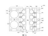
根據至少一實施例,圖3A繪示出在處理氣體調節組件300之x-y平面中之平面圖。在至少一實施例中,處理氣體調節組件300包括與表面安裝基底102之橫向側壁122相鄰之處理氣體貯存器子組件118。在至少一實施例中,處理氣體貯存器子組件118包括貯存器殼體塊126。在至少一實施例中,如圖所示,處理氣體調節組件300更包括加熱板302,與表面安裝基底102之相對橫向側壁124相鄰。在至少一實施例中,加熱板302包括非平面側壁304。在至少一實施例中,非平面側壁304可實質上與非平面側壁154相同。在至少一實施例中,加熱板302可實質上類似於沒有貯存器井(例如,貯存器井136及138)之貯存器殼體塊128。在至少一實施例中,加熱板302可使用做為處理氣體調節組件300之選用的模組化構件。在至少一實施例中,加熱板302可與貯存器殼體塊126或128互相交換。在一些實施例中,加熱板302可與貯存器殼體塊128互相交換,貯存器殼體塊128亦為模組化構件。在至少一實施例中,模組之可互換性可提供處理氣體調節組件100至處理氣體調節組件300之快速轉換。在至少一實施例中,由處理氣體調節組件300所提供之貯存器組可提供更有效及緊湊的安裝。According to at least one embodiment, FIG. 3A illustrates a plan view in the x-y plane of a process
在至少一實施例中,加熱板302可包括不銹鋼、赫史特合金、或其它合適的高溫且化學抗性材料。在至少一實施例中,加熱板302可,例如,由不銹鋼或赫史特合金之單一塊料加工而成、或藉由例如3D列印之加法式處理而製造。在至少一實施例中,加熱板302可包括非平面側壁304。在至少一實施例中,非平面側壁304可包括凹陷輪廓及凹槽特徵,在形式及功能兩者上與貯存器殼體塊128之凹陷輪廓及凹槽特徵實質上相同。In at least one embodiment, the
在至少一實施例中,非平面側壁304包括凹陷輪廓306。在至少一實施例中,凹陷輪廓306可與貯存器殼體塊128之凹陷輪廓156a-d相似或實質上相同。如圖3A所示,凹陷輪廓306通常可符合表面安裝構件104之形狀,如上所述。在至少一實施例中,凹陷輪廓306可包括圓弧,其使得在表面安裝構件104與凹陷輪廓306之間能夠有效熱接觸。在至少一實施例中,凹陷輪廓306之圓弧可與表面安裝構件104共形,其通常可具有圓柱形形狀。在至少一實施例中,凹槽308可凹入非平面側壁304中至低於凹陷輪廓306之深度。在至少一實施例中,凹槽308可與在貯存器殼體塊128之非平面側壁154中之凹槽158實質上相同。在至少一實施例中,例如,凹槽308可提供熱接觸給立管152。在至少一實施例中,例如,非平面側壁304之上平坦部分310可凹陷以提供間隙,用於旋鈕166之手動操縱(參見圖3B)。在至少一實施例中,加熱板302可包括加熱器筒井322,以提供熱給加熱板302。可採用任何適當數量之加熱器筒井322。在至少一實施例中,加熱器筒井322可垂直地定向(如圖所示)、及∕或水平地定向穿過外側壁324或前側壁326。In at least one embodiment, the
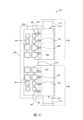
根據至少一實施例,圖3B繪示出在處理氣體調節組件300之x-z平面中之剖視圖。在至少一實施例中,貯存器殼體塊126係顯示為具有伴隨的貯存器軛200。在至少一實施例中,裝料容積罐202係顯示為從貯存器井130部分地抽出。與處理氣體貯存器子組件118相比,加熱板302可為表面安裝構件104及氣體管線配管160及立管152提供同樣有效的加熱。According to at least one embodiment, FIG3B depicts a cross-sectional view in the x-z plane of the process
在至少一實施例中,加熱板302具有比貯存器殼體塊128更小的橫向佔地面積。根據至少一實施例,因為加熱板302提供更小的佔地面積,所以與處理氣體調節組件100相比,處理氣體調節組件300可具有更緊湊的總體佔地面積。在至少一實施例中,處理氣體調節組件300可具有處理氣體調節組件100之佔地面積之60% 或更小。在至少一實施例中,在處理氣體調節及分配設備之放置之空間可能受限的地方,處理氣體調節組件300之更緊湊的配置可適合處理工具安裝。在至少一實施例中,可調整在加熱板302之下平坦部分312與表面安裝基底102之橫向側壁124之間之距離,以進一步減少佔地面積。In at least one embodiment, the
在至少一實施例中,貯存器殼體塊126可交換為與加熱板302實質上相同之第二加熱板。在至少一實施例中,如果需要的話,裝料容積罐202及204或直接處理氣體源可藉由遠端方式被加熱,並且可遠端耦接至表面安裝基底102。In at least one embodiment,
根據至少一實施例,圖3C繪示出在處理氣體調節組件350之x-z平面中之剖視圖,類似於處理氣體調節組件300。在至少一實施例中,處理氣體調節組件350包括處理氣體貯存器子組件352。在至少一實施例中,處理氣體貯存器子組件352包括貯存器殼體塊353及水平(例如,在圖之x或y方向上)定向的貯存器軛(例如,包括裝料容積罐202及204之貯存器軛200,圖2)。在至少一實施例中,為了清楚起見,貯存器軛及裝料容積罐被省略。在至少一實施例中,貯存器殼體塊353內之貯存器井354及356可從側壁358水平地延伸(在圖之y方向上,在圖之平面下方)。在至少一實施例中,貯存器井354及356之水平定向可使得容納在貯存器殼體塊353內之處理裝料容積罐(未顯示)能夠方便接近。在至少一實施例中,在受限的空間中,頂部可接近之垂直定向的裝料容積可能難以在不拆卸整個組件之情況下進行維修。在至少一實施例中,在這樣的情況下,水平定向的裝料容積罐可更方便從側邊接近。According to at least one embodiment, FIG. 3C depicts a cross-sectional view in the x-z plane of a process
在至少一實施例中,貯存器殼體塊353包括非平面側壁360。在至少一實施例中,非平面側壁360與在圖1A及1B中所繪示之貯存器殼體塊126之非平面側壁144實質上相同。在至少一實施例中,非平面側壁360可包括凹陷輪廓(例如凹陷輪廓156a-d)及凹槽(例如凹槽158a-d)。In at least one embodiment, the
在至少一實施例中,處理氣體調節組件350可具有模組化架構,其中一處理氣體貯存器子組件352或二這樣的子組件可與表面安裝基底102進行組裝。在至少一實施例中,單一處理氣體貯存器子組件352係顯示為與表面安裝基底102之橫向側壁122相鄰。在至少一實施例中,第二處理氣體貯存器子組件(例如,與處理氣體貯存器子組件352類似或實質上相同)可與橫向側壁124(例如,位在此圖之右側上之表面安裝基底102之側面)相鄰而進行組裝。在至少一實施例中,在表面安裝基底102之右側上之表面安裝構件104係露出的,從氣體管線配管160而延伸之立管152也是如此。在至少一實施例中,第二加熱板(例如,加熱板302)可放置為與表面安裝基底102之橫向側壁124相鄰,以模組化的方式完成組裝。In at least one embodiment, the process
根據至少一實施例,圖4A繪示出在處理氣體調節組件400之x-z平面中之剖視圖。在至少一實施例中,處理氣體調節組件400包括表面安裝基底102。在至少一實施例中,表面安裝構件402及404係顯示為安裝在表面安裝基底102之表面106上。在至少一實施例中,處理氣體調節組件400更包括平台406,從表面安裝基底102之橫向側壁124橫向地延伸。在至少一實施例中,平台406可支撐貯存器殼體塊408及貯存器殼體塊410,以提供熱接觸。在至少一實施例中,貯存器殼體塊408及410可分別定位在平台406之上表面412及下表面414上。在至少一實施例中,裝料容積罐(未顯示)可插入在貯存器殼體塊408及410內之貯存器井416及418中。在至少一實施例中,貯存器殼體塊408及410可包括加熱器筒井420。在至少一實施例中,容納在加熱器筒井420內之電加熱器筒可提供熱給在貯存器殼體塊408及410內所含之處理氣體。在至少一實施例中,處理氣體調節組件400可提供比先前所述的實施例(例如,處理氣體調節組件100及300)更緊湊的形式因子。According to at least one embodiment, FIG. 4A illustrates a cross-sectional view in the x-z plane of a process
在至少一實施例中,在處理氣體調節組件400中可包括噴淋頭入口配接器422。在至少一實施例中,噴淋頭入口配接器422可提供似基座的結構以支撐處理氣體調節組件400。在至少一實施例中,噴淋頭入口配接器422可提供殼體,用於在處理氣體調節組件400與半導體處理工具(例如,在圖7中所示)之化學氣相沉積(或原子層沉積)處理腔室內之噴淋頭之間佈線之配管。在至少一實施例中,噴淋頭入口配接器422包括加熱器筒,用於加熱佈線在內之配管。In at least one embodiment, a
根據至少一實施例,圖4B繪示出在處理氣體調節組件450之x-z平面中之剖視圖。在至少一實施例中,處理氣體調節組件450可包括處理氣體調節組件400及鏡基底452,鏡基底452係從(主)表面安裝基底102之橫向側壁122而橫向延伸。在至少一實施例中,鏡基底452可提供輔助氣體流動基底,結構類似於表面安裝基底102,例如,以容納表面安裝構件454及456。表面安裝構件454及456可在物理上小於表面安裝構件402及404。在至少一實施例中,例如,安裝在鏡基底452上之表面安裝構件之較小尺寸可使得載氣之細流能夠更有效操作。在至少一實施例中,其它構件(例如,平台406、貯存器殼體塊408及410)可與對於處理氣體調節組件400所述者實質上相同。According to at least one embodiment, FIG. 4B illustrates a cross-sectional view in the x-z plane of a process
根據至少一實施例,圖4C繪示出在處理氣體調節組件460之x-y平面中之平面圖。在至少一實施例中,處理氣體調節組件460包括表面安裝基底462、以及處理氣體貯存器子組件464及466。在至少一實施例中,處理氣體貯存器子組件464及466以及表面安裝基底462可安裝在支撐板468上。在至少一實施例中,處理氣體貯存器子組件464及466分別包括塊465及467。在至少一實施例中,兩者與表面安裝基底462之側壁470相鄰,沿著側壁470彼此移位。在至少一實施例中,處理氣體貯存器子組件464及466更分別包括裝料容積貯存器472及474,分別安置在貯存器井476及478內(箭頭指向由隱藏線所描繪之貯存器井之開口)。在至少一實施例中,裝料容積貯存器472及474係顯示為分別地部分安置於貯存器井476及478內。According to at least one embodiment, FIG. 4C depicts a plan view in the x-y plane of the process
在至少一實施例中,貯存器井476及478係定向為平行於表面安裝基底462之側壁470。在至少一實施例中,貯存器井476及478係沿著圖之y方向、實質上平行於側壁470而延伸。在至少一實施例中,貯存器井476及478之平行而非正交的定向可實現處理氣體調節組件460之更緊湊的架構。In at least one embodiment,
在至少一實施例中,塊465及467分別包括非平面側壁480及482。在至少一實施例中,非平面側壁480及482分別包括複數凹陷輪廓484及486,且分別包括複數凹槽488及490。在至少一實施例中,個別的凹槽488及490係切入非平面側壁480及482至一深度,該深度係延伸低於凹陷輪廓484及486之深度。在至少一實施例中,凹槽488及490可切穿凹陷輪廓484及486,如圖所示,以從非平面側壁482延伸預定距離。In at least one embodiment, blocks 465 and 467 include
在至少一實施例中,包括立管492(在圖之z方向上延伸)之複數氣體管線配管段可從表面安裝基底462橫向地延伸。在至少一實施例中,可分別預先決定凹槽488及490從非平面側壁480及482之深度,以容納立管492從表面安裝基底462之側壁470之橫向移位。立管492可沿著凹槽488及490延伸,凹槽488及490可至少部分地垂直定向(例如,在圖之z方向上)。在至少一實施例中,立管492可與凹槽488及490之壁熱接觸。在至少一實施例中,熱接觸可為在立管492之壁與凹槽488及490之壁之間之直接機械接觸。在一實施例中,立管492及凹槽488及490可不具有直接機械接觸。在至少一實施例中,小間隙(例如,1 mm或更小)可存在於立管492與凹槽488及490之間。In at least one embodiment, a plurality of gas line piping sections including a riser 492 (extending in the z-direction of the figure) may extend laterally from the
在至少一實施例中,凹陷輪廓484及486可包括圓弧,其可部分地圍繞表面安裝基底462上之表面安裝構件494。在至少一實施例中,凹陷輪廓484及486可與表面安裝構件494熱接觸,如上所述。在至少一實施例中,凹陷輪廓484及486之壁可與表面安裝構件494直接機械接觸。在至少一實施例中,間隙(1 mm或更小)可存在於凹陷輪廓之壁與表面安裝構件494之表面之間。In at least one embodiment, the recessed
根據至少一實施例,圖5A繪示出在處理氣體調節組件500之x-y平面中之平面圖。在至少一實施例中,處理氣體調節組件500包括表面安裝基底502,其側面有處理氣體貯存器子組件118及120。在至少一實施例中,表面安裝基底502包括三氣體流動通道(未顯示),在表面504下方延伸。在至少一實施例中,個別的表面下流動通道可分別流體耦接至表面安裝構件104。在至少一實施例中,表面安裝構件104被分組為可與表面下氣體流動通道對準之三列506、508及510(由虛線框所描繪)。According to at least one embodiment, FIG. 5A illustrates a plan view in the x-y plane of a process
除了表面安裝基底502之外,以上所提出之對於處理氣體調節組件100之描述可實質上適用於處理氣體調節組件500。在至少一實施例中,處理氣體貯存器子組件118及120實質上如上所述並且如圖1A及1B所示。在至少一實施例中,表面安裝基底502(具有三流動通道架構)可為表面安裝基底102(包含雙流動通道架構)之擴充。在至少一實施例中,氣體調節基底可包括四或更多處理氣體流動通道。在至少一實施例中,表面安裝基底102及502可分別為可互相交換的。在至少一實施例中,表面安裝基底502(例如,做為三流動通道基底模組)可與表面安裝基底102(例如,雙流動通道基底模組)交換,因而使處理氣體調節組件100或300能夠轉換為處理氣體調節組件500。Except
在至少一實施例中,表面安裝基底502(包括三表面下處理氣體流動通道)可使用於二前驅物氣體與第三氣體流進行混合之實施例。在至少一實施例中,第三氣體流可包括反應性處理氣體。在至少一實施例中,第三氣體流可包括含有聯氨、氫、及∕或氨之還原性混合物。在至少一實施例中,混合物亦可為氧化性的,包括水蒸氣、氧、臭氧、一氧化二氮等。In at least one embodiment, the surface mount substrate 502 (including three subsurface process gas flow channels) can be used in embodiments where two precursor gases are mixed with a third gas stream. In at least one embodiment, the third gas stream can include a reactive process gas. In at least one embodiment, the third gas stream can include a reducing mixture containing hydrazine, hydrogen, and/or ammonia. In at least one embodiment, the mixture can also be oxidizing, including water vapor, oxygen, ozone, nitrous oxide, etc.
在至少一實施例中,處理氣體調節組件500可更包括受到加熱的端板,例如在圖1E中所示之受到加熱的端板184。在至少一實施例中,加熱板(例如圖3A及3B中所示之加熱板302)可被交換成處理氣體貯存器子組件118及∕或120其中一或兩者。In at least one embodiment, the process
根據至少一實施例,圖5B繪示出在處理氣體調節組件500在x-z平面中之剖視分解圖,包括表面安裝基底502、以及處理氣體貯存器子組件118及120。在至少一實施例中,處理氣體貯存器子組件118及120可分別包括貯存器軛200a及貯存器軛200b。在至少一實施例中,貯存器軛200a及200b可實質上類似於如圖2所示並且如上所述之處理氣體貯存器子組件118。在至少一實施例中,貯存器軛200a及200b分別包括裝料容積罐202a及202b。According to at least one embodiment, FIG. 5B illustrates a cross-sectional exploded view of a process
在至少一實施例中,裝料容積罐202a及202b可安置於貯存器殼體塊126中之貯存器井130及138(未顯示)內。在至少一實施例中,裝料容積罐202a及202b可安置於貯存器井130及貯存器井138內。在至少一實施例中,貯存器井130及138之垂直範圍係由貯存器殼體塊126及128中之隱藏線所指示。In at least one embodiment, the
根據至少一實施例,圖5B亦顯示出在表面安裝基底502之前側壁518中之終端埠512、514及516。在至少一實施例中,終端埠512-516可通往表面安裝基底502之三表面下處理氣體流動通道。在至少一實施例中,例如,終端埠512-516可為輸送惰性載氣(例如,氬)進入表面下流動通道之處理氣體管線之進入點。5B also shows
根據至少一實施例,圖6A繪示出在預熱器組件600之x-y平面中之平面分解圖,包括配置成堆疊組件之二或更多板。在至少一實施例中,預熱器組件600可為處理氣體調節組件100或500之構件。在至少一實施例中,預熱器組件600可用於預熱某些處理氣體,在將處理氣體引入處理氣體調節組件之表面安裝基底構件(例如,表面安裝基底502)之前。在至少一實施例中,預熱器組件包括板602、604、606及608。在至少一實施例中,板602-608可配置成堆疊組件。在至少一實施例中,板602-608可提供熱質量,用於將熱傳遞至穿過預熱器組件600之氣體管線配管段。在至少一實施例中,如下所述,氣體管線配管段可在相鄰板之間通過。在至少一實施例中,板602-608可包括導熱材料,例如,但不限於,鋁、銅、黃銅、或不銹鋼。在至少一實施例中,板602-608可具有長斜方形橫剖面,如平面圖中所示。在至少一實施例中,板602-808之長斜方形橫剖面可賦予預熱器組件600長斜方形佔地面積。在至少一實施例中,長斜方形狀可最小化預熱器組件600之橫向佔地面積。According to at least one embodiment, FIG. 6A depicts an exploded view of a
在圖6A之分解圖中,板602-608是分開的,以繪示出氣體管線配管段610、612及614。在至少一實施例中,氣體管線配管段610、612及614(由虛線框所描繪)可設置於成對的單獨板之間。在至少一實施例中,氣體管線配管段610設置於板602與604之間。在至少一實施例中,氣體管線配管段612可設置於板604與606之間,且氣體管線配管段612可設置於板606與608之間。應當理解,在組裝狀態下,氣體管線配管段610-614通常嵌入在板602-608內。在至少一實施例中,板602、604、606及608其中一些可包括凹槽616、618及620,分別用於嵌入氣體管線配管段610、612及614。In the exploded view of FIG. 6A , the plates 602-608 are separated to illustrate the gas
在至少一實施例中,氣體管線配管段610-614可分別包括複數子段622、624及626。在至少一實施例中,氣體管線配管段610-614可,例如,藉由90°彎頭628、630及632以蛇形配置互連。在至少一實施例中,氣體管線配管段610-614之蛇形配置可最大化在板602-608與氣體管線配管段610-614之間之熱接觸,用於預熱器組件600之緊湊體積。雖然圖6A之平面圖顯示出平行於圖之平面而延伸之一些互連的氣體管線配管段,但應理解,一些段係相對於平行段而正交地延伸(例如,在圖之平面下方)。圖6B顯示出互連的氣體管線配管段之蛇形配置之範例。在至少一實施例中,在至少一平面(例如,x-y平面)中,板602-608可具有長斜方形橫剖面。在至少一實施例中,預熱器組件600之長斜方形橫剖面可提供緊湊的佔地面積,同時提供與氣體管線配管段610-614之最大熱接觸。In at least one embodiment, the gas line piping segments 610-614 may include a plurality of
在至少一實施例中,氣體管線配管段610-614可為單獨且獨立的氣體輸送流動路徑之分段,將處理氣體以單獨管線佈線至處理氣體調節組件。In at least one embodiment, the gas line piping segments 610-614 may be segments of separate and independent gas delivery flow paths that route the process gas to the process gas conditioning assembly in separate pipelines.
在至少一實施例中,板604及606在堆疊組件之中間部分中相鄰,分別包括加熱器筒井634及636,用於安置加熱器筒。在至少一實施例中,板604及606是模組化的,使得預熱器組件600可建構成客製化尺寸,以容納更多或更少數量的氣體管線配管段。在至少一實施例中,板604及606可為實質上相同之至少二中間板。中間板(例如,板604及606)可定位在「書擋」或「端蓋」板602與608之間。如圖6A所示,二中間板及二端蓋板可容納三單獨的氣體管線。在至少一實施例中,中間板(例如,板602及608)可實質上彼此相同,但具有與板604及606不同的設計。雖然在所繪示的實施例中在預熱器組件600中包括總共四板,但可包括與板604及606類似或相同之任何合適數量的中間板。在至少一實施例中,在堆疊組件內之六板(例如,在二端蓋板之間之四中間板)可使得五氣體管線能夠穿過預熱器組件600。在至少一實施例中,預熱器組件600之模組化可使得更多板能夠根據需要而添加。在至少一實施例中,較多數量的板係使得較多數量的單獨氣體管線配管段能夠穿過預熱器組件600。在至少一實施例中,N個板之堆疊可容納N-1條單獨的氣體管線。In at least one embodiment,
在至少一實施例中,加熱器筒可安置在加熱器筒井634及636內以提供熱給氣體管線配管段610-614。在至少一實施例中,可採用適當數量之加熱器筒,以提供需要的熱給穿過預熱器組件600之氣體管線段內之流動氣體。In at least one embodiment, heater cartridges may be placed in
根據至少一實施例,圖6B繪示出在預熱器組件600之y-z平面中之橫剖面圖。所繪示的實施例係將氣體管線配管段610(由虛線框所描繪)顯示為與板602鄰近且鄰接之單一氣體管線段。雖然在所繪示的實施例中係顯示出板602,但應可理解,在預熱器組件600之堆疊內之其它板604、606及608以及相鄰的氣體管線配管段612及614可被同等地顯示。在至少一實施例中,氣體管線配管段610可安置於凹槽616內。在至少一實施例中,凹槽616可包括複數正交區段,如圖所示,其遵循氣體管線配管段610之蛇形構造。在至少一實施例中,上配管短管638及下配管短管640可透過壓合接頭642而提供與外部氣體管線配管之互連。According to at least one embodiment, FIG. 6B depicts a cross-sectional view in the y-z plane of the
根據至少一實施例,圖6C繪示出在包括預熱器組件600a及600b之處理氣體調節組件500之x-y平面中之平面圖。在至少一實施例中,處理氣體調節組件500包括雙預熱器組件(例如,預熱器組件600a及600b),如圖所示。在至少一實施例中,處理氣體調節組件500可包括單一預熱器組件(例如,預熱器組件600a或600b)。在至少一實施例中,預熱器組件600a係定位在歧管206a上方,安裝在貯存器殼體塊126之上表面上。According to at least one embodiment, FIG. 6C depicts a plan view in the x-y plane of the process
在至少一實施例中,預熱器組件600a及600b可分別耦接至與貯存器殼體塊126及128相鄰之一或更多立管152。在至少一實施例中,氣體管線配管段610a、612a及614a可透過在下配管短管640(由圖6C中之隱藏線所示;參見圖6B及6D)之末端上之壓合接頭642而耦接至從表面安裝基底502(例如,左側)延伸之立管152。在至少一實施例中,預熱器組件600a可與在貯存器殼體塊126之上表面(例如,表面134)上之歧管206a垂直偏移大約下配管短管640之長度,如圖6D中所示。In at least one embodiment, the
在至少一實施例中,預熱器組件600b可定位在貯存器殼體塊128上之歧管206b上方。在至少一實施例中,氣體管線配管段610b、612b及614b可耦接至從與貯存器殼體塊128相鄰之表面安裝基底502(例如,右側)延伸之立管152。在至少一實施例中,在預熱器組件600b上之下配管短管640(由隱藏線所示)亦可從歧管206b垂直偏移類似或實質上相同之預熱器組件600a之偏移距離。In at least one embodiment, the
在至少一實施例中,預熱器組件600a及600b可在至少一平面(例如,如圖所示之x-y平面)中具有長斜方形橫剖面。如上所述,預熱器組件600a及600b之長斜方形形狀可限制預熱器組件600a及600b之寬度w(例如,在圖之x方向上之橫向範圍)。在至少一實施例中,在預熱器組件600之內壁與氣體管線配管段610-614之間之熱接觸可藉由優化長斜方形角度α而最大化。在至少一實施例中,可調整角度α以使與預熱器堆疊板(例如,在圖6A中之板602-608)接觸之氣體管線配管段610-614之總長度最大化。同時,預熱器組件600a及600b之寬度w可藉由角度α之最佳化而最小化。In at least one embodiment, the
圖6D繪示出在處理氣體調節組件500之x-z平面中之剖視圖,包含如圖6C中所示之預熱器組件600a及600b。根據至少一實施例,圖6D顯示出分別與貯存器殼體塊126及128垂直相對之預熱器組件600a及600b。在至少一實施例中,氣體管線配管段(例如,氣體管線配管段610-614)由在預熱器組件600a及600b內之隱藏線所指示。在至少一實施例中,氣體管線配管段可埋入在預熱器組件600a及600b內,例如以圖中所示之蛇形結構。在至少一實施例中,預熱器組件600a及600b可透過下配管短管640a及640b而耦接至處理氣體調節組件,下配管短管640a及640b係耦接至在表面安裝基底502之相對側上之立管152。在至少一實施例中,預熱器組件600a及600b可與安裝在貯存器殼體塊126及128之上表面上之歧管206a及206b垂直地偏移高度h。在至少一實施例中,高度h可實質上取決於下配管短管640a及640b之長度。FIG. 6D illustrates a cross-sectional view in the x-z plane of the process
在至少一實施例中,耦接至處理氣體調節組件500之外部氣體管線可包括前級管線加熱器套644,用於加熱一些處理氣體(例如,氫)。在至少一實施例中,前級管線加熱器套644可與預熱器組件600a及∕或600b成連線,例如耦接至上配管短管638a及638b。在至少一實施例中,前級管線加熱器套644可提供額外的加熱。在至少一實施例中,在處理氣體外部流動路徑中可包括一或更多受到加熱的閥646。In at least one embodiment, the external gas line coupled to the process
根據至少一實施例,圖7繪示出在半導體處理工具700之x-z平面中之橫剖面圖,包括處理氣體調節組件500。應可理解,雖然在範例中顯示出處理氣體調節組件500(顯示在圖5A及圖5B中),但處理氣體調節組件之其它揭示的實施例(例如,處理氣體調節組件100及處理氣體調節組件300)可同樣地使用在範例中。在至少一實施例中,半導體處理工具700包括真空腔室702。在至少一實施例中,噴淋頭704係設置在真空腔室702內靠近上壁706。在至少一實施例中,處理氣體調節組件500可透過延伸穿過噴淋頭入口配接器721之導管708、導管710及導管712而流體耦接至噴淋頭70。在至少一實施例中,噴淋頭入口配接器721亦可提供處理氣體調節組件500之機械支撐以及用於導管708、710及712之殼體。According to at least one embodiment, FIG. 7 illustrates a cross-sectional view in the x-z plane of a
在所繪示的實施例中,導管708及710從表面安裝基底502之下表面720延伸。在至少一實施例中,導管708、710及712可流體耦接至在表面安裝基底502內之三表面下氣體流動通道。在至少一實施例中,導管708-712可延伸穿過噴淋頭入口配接器721之空腔723(例如,管狀空腔),如圖所示。在至少一實施例中,個別的導管708-712可終止於通往噴淋頭704之腔室之環形孔洞(未顯示)。在至少一實施例中,三表面下處理氣體流動通道可耦接至在表面安裝基底502之前側壁518上之終端埠512、514及516。在至少一實施例中,終端埠512、514及516可耦接至氣體管線配管,氣體管線配管將惰性載氣(例如,氬或氮)輸送至在表面安裝基底502中之表面下氣體流動通道。在至少一實施例中,在導管708、710及712與表面安裝基底502中之內部流動通道之間之內部耦接係由在表面安裝基底502之下表面720分別與終端埠512、514及516之間延伸之隱藏線所指示。在至少一實施例中,導管708及712可分別將第一預調節前驅物處理氣體(例如,第一前驅物物質之蒸氣)及第二預調節前驅物處理氣體(例如,第二前驅物物質之蒸氣)輸送至噴淋頭704。在至少一實施例中,導管710可將第三預調節處理氣體做為蒸氣或反應性氣體而輸送至噴淋頭704。在至少一實施例中,由導管708-712所輸送之三單獨的處理氣體可在噴淋頭704內混合、或通過噴淋頭704之面板722而分別地流至真空腔室702中。In the illustrated embodiment,
在至少一實施例中,噴淋頭704可操作以將經過預調節的處理氣體分配至真空腔室702中。在至少一實施例中,處理氣體可藉由通過處理氣體調節組件500以進行預調節。在至少一實施例中,例如,在操作期間,第一及第二處理氣體可在壓力下容納在裝料容積貯存器(例如,由貯存器軛200a及200b所帶有之裝料容積罐202a及202b,如圖5B所示)內。在至少一實施例中,貯存器軛200a及200b之歧管206a及206b係顯示為分別安置於貯存器殼體塊126及128上。在至少一實施例中,裝料容積罐202a及202b係插入在貯存器殼體塊126及128中之貯存器井130及138內。在至少一實施例中,第三處理氣體(例如,惰性或反應性載氣)可經由立管152及氣體管線配管160之一或兩者而引入至表面安裝基底102內之表面下流動通道中。在至少一實施例中,立管152可耦接至處理氣體供應724。In at least one embodiment, the
在至少一實施例中,處理氣體可被預調節,例如,藉由通過預熱器組件725及727(例如,如關於圖6A-6D所述)以及在表面安裝基底502上之表面安裝構件(例如,表面安裝構件104)。在至少一實施例中,處理氣體操作構件可包括流量控制閥、混合器、及氣體過濾器。在至少一實施例中,處理氣體貯存器子組件118及120可藉由在貯存器殼體塊126及128內之加熱器筒726而加熱,使得容納在裝料容積罐(例如,圖5B之裝料容積罐202a及202b)內之處理氣體可維持在升高的溫度下。在至少一實施例中,加熱器筒726可為耦接至溫度控制器728之電加熱器筒。In at least one embodiment, the process gas can be pre-conditioned, for example, by passing through
在至少一實施例中,在表面安裝構件104內之冷點,例如,可能導致在表面安裝構件之內部通道內之冷凝或結晶。在至少一實施例中,表面安裝構件104可藉由分別與非平面側壁144及154之熱接觸而被加熱。在至少一實施例中,立管152亦可藉由分別與在貯存器殼體塊126及128中之側壁凹槽(例如,在非平面側壁144內之凹槽150、以及在非平面側壁154內之凹槽158)熱接觸而維持在升高的溫度。In at least one embodiment, cold spots within the
在至少一實施例中,噴淋頭入口配接器721亦可包括內部加熱元件,以防止蒸氣,在進入噴淋頭704之前,在導管708、710及712內冷凝。在至少一實施例中,在操作期間,處理氣體可從噴淋頭704流至真空腔室702中。在至少一實施例中,從噴淋頭704流出之處理氣體可被引導至支撐在基座732上之晶圓730,基座732包括卡盤734及柱736。在至少一實施例中,噴淋頭704可分配處於層流之處理氣體以用於原子層沉積(ALD)或化學氣相沉積(CVD)處理。在至少一實施例中,ALD或CVD處理可在晶圓730之表面上形成非晶、單晶或多晶膜。在至少一實施例中,晶圓730可藉由卡盤734而加熱至升高的溫度以支援非晶、單晶、或多晶膜之形成。In at least one embodiment, the
根據至少一實施例,圖8繪示出用於操作處理氣體調節組件100(還有處理氣體調節組件300及500)之方法之流程圖800。流程圖800之各種操作可藉由硬體、軟體或其組合來實施。在至少一實施例中,方法流程圖800繪示出所揭示的處理氣體調節組件(例如,處理氣體調節組件100)之示例性操作,以對在半導體處理操作中所採用之處理氣體進行預調節。在至少一實施例中,例如,在進入半導體處理工具(例如,在圖7中所示之半導體處理工具700)之前,處理氣體可藉由處理氣體調節組件100而進行預調節。According to at least one embodiment, FIG. 8 illustrates a flow chart 800 of a method for operating the process gas conditioning assembly 100 (and process
在至少一實施例中,在操作801,處理氣體調節組件100被預熱至預定的升高溫度。在至少一實施例中,預熱可包括藉由溫度控制器之加熱整合式加熱筒之啟動。In at least one embodiment, the process
在至少一實施例中,當處理氣體調節組件100之溫度穩定時,容納在裝料容積罐(例如,裝料容積罐202及204,如圖2中所示)內之處理氣體可開始在表面安裝基底(例如,表面安裝基底102或502)之表面下流動通道(例如,氣體流動通道108)內流動。In at least one embodiment, when the temperature of the process
在至少一實施例中,在操作802及803,表面安裝閥可打開,例如藉由發送至閥上之致動器之電子命令,以啟動處理氣體流入耦接至表面安裝基底之氣體管線配管。在至少一實施例中,氣體管線配管可穿過預熱器站(例如,預熱器組件600)。在至少一實施例中,預熱器站可將在氣體管線配管內流動之處理氣體預熱至與處理氣體調節組件之溫度緊密匹配之溫度。在至少一實施例中,處理氣體之流動可接著在表面下流動通道內行進。In at least one embodiment, at operations 802 and 803, the surface mounted valve may be opened, such as by an electronic command sent to an actuator on the valve, to initiate the flow of process gas into a gas line piping coupled to the surface mounted substrate. In at least one embodiment, the gas line piping may pass through a preheater station (e.g., preheater assembly 600). In at least one embodiment, the preheater station may preheat the process gas flowing in the gas line piping to a temperature that closely matches the temperature of the process gas conditioning assembly. In at least one embodiment, the flow of process gas may then proceed in a subsurface flow channel.
在至少一實施例中,處理氣體亦可流過附接至表面安裝基底之任何表面安裝構件,因為它們流體耦接至表面下流動通道。在至少一實施例中,表面安裝構件可控制流率、將流動轉向至其它路徑、將反應性處理氣體與惰性或反應性載氣加以混合、過濾處理氣體之微粒等。在至少一實施例中,預調節處理氣體在進入半導體處理工具之前可包括在表面安裝基底中之表面下流動通道內流動之處理氣體之被動加熱、混合及過濾。In at least one embodiment, the process gas may also flow through any surface mount components attached to the surface mount substrate because they are fluidly coupled to the subsurface flow channel. In at least one embodiment, the surface mount components may control the flow rate, divert the flow to other paths, mix the reactive process gas with an inert or reactive carrier gas, filter particles of the process gas, etc. In at least one embodiment, pre-regulating the process gas may include passive heating, mixing, and filtering of the process gas flowing in the subsurface flow channel in the surface mount substrate before entering the semiconductor processing tool.
在至少一實施例中,在操作804及805,處理氣體流可進入半導體處理工具(例如,半導體處理工具700)之沉積處理腔室(例如,圖7中所示之真空腔室702)。在沉積處理腔室內,藉由使經過預調節的處理氣體流出經過噴淋頭(例如,圖7中所示之噴淋頭704)而進入沉積處理腔室中,可實施沉積處理。在至少一實施例中,當腔室保持在高真空時,經過預調節的處理氣體可從噴淋頭中之孔口、以複數層流噴射而流出。在至少一實施例中,處理氣體可包括反應性及惰性載氣、混合氣體、以及來自在室溫下為液體或固體之前驅物物質之蒸氣。In at least one embodiment, at operations 804 and 805, a process gas flow may enter a deposition processing chamber (e.g.,
在至少一實施例中,經過預調節的處理氣體可撞擊在噴淋頭下方之晶圓(例如,圖7中所示之晶圓730)上。在至少一實施例中,根據處理條件、表面反應、及前驅物物質之性質,結晶薄膜可生長在晶圓上成為原子層或分子層。在至少一實施例中,可建構複數層以形成具有期望厚度之膜。在至少一實施例中,在一些處理中,薄膜為非晶形的。In at least one embodiment, the preconditioned process gas may impinge on a wafer (e.g.,
在至少一實施例中,在操作806,可藉由停止處理氣體流以關閉處理。在至少一實施例中,停止處理氣體之流動可包括,關閉在表面安裝基底上之控制表面安裝閥。在至少一實施例中,加熱器筒可保持啟動,以允許載氣吹淨剩餘的可冷凝蒸氣。在至少一實施例中,吹淨持續時間可為預定的。在至少一實施例中,一旦所有可冷凝蒸氣被吹淨,則加熱器筒可斷電,以允許處理氣體調節組件冷卻。In at least one embodiment, at operation 806, the process can be shut down by stopping the flow of process gas. In at least one embodiment, stopping the flow of process gas can include closing a control surface mounted valve on the surface mounted substrate. In at least one embodiment, the heater cartridge can remain activated to allow the carrier gas to purge remaining condensable vapors. In at least one embodiment, the purge duration can be predetermined. In at least one embodiment, once all condensable vapors are purged, the heater cartridge can be de-energized to allow the process gas conditioning assembly to cool.
提供以下範例以說明各種實施例。該等範例可與其它範例進行組合。因此,各種實施例可與其它實施例組合而不改變本發明之範圍。The following examples are provided to illustrate various embodiments. These examples can be combined with other examples. Therefore, various embodiments can be combined with other embodiments without changing the scope of the present invention.
範例1係一種氣體調節組件,包括:一表面安裝基底,其中該表面安裝基底包括複數孔洞,其中一第一氣體流動通道係延伸在該表面安裝基底內,及其中一第二氣體流動通道係與該第一氣體流動通道相鄰;及一處理氣體貯存器子組件,其中該處理氣體貯存器子組件係與該表面安裝基底相鄰並且包括一貯存器殼體塊及一貯存器軛,其中該貯存器軛係包括在該貯存器殼體塊內之至少一氣體貯存器,其中該貯存器殼體塊係包括與該表面安裝基底相鄰之一非平面側壁,其中該非平面側壁係包括沿著該非平面側壁而延伸之複數凹槽及複數凹陷輪廓,其中一或更多凹陷輪廓係與安裝在該表面安裝基底上之一或更多表面安裝構件熱接觸,及其中一或更多凹槽係與從該表面安裝基底而延伸之一或更多氣體管線配管段熱接觸。Example 1 is a gas conditioning assembly, comprising: a surface mount substrate, wherein the surface mount substrate includes a plurality of holes, wherein a first gas flow channel extends within the surface mount substrate, and wherein a second gas flow channel is adjacent to the first gas flow channel; and a process gas reservoir subassembly, wherein the process gas reservoir subassembly is adjacent to the surface mount substrate and includes a reservoir housing block and a reservoir yoke, wherein the reservoir yoke is included in the At least one gas reservoir in a reservoir housing block, wherein the reservoir housing block includes a non-planar sidewall adjacent to the surface mounting base, wherein the non-planar sidewall includes a plurality of grooves and a plurality of recessed profiles extending along the non-planar sidewall, wherein one or more of the recessed profiles are in thermal contact with one or more surface mounting components mounted on the surface mounting base, and wherein one or more of the grooves are in thermal contact with one or more gas pipeline piping sections extending from the surface mounting base.
範例2係所述範例其中任一者,尤其是範例1,之氣體調節組件,其中一或更多第一表面安裝構件係流體耦接至該第一氣體流動通道,及其中一或更多第二表面安裝構件係流體耦接至該第二氣體流動通道。Example 2 is a gas conditioning assembly of any of the examples, particularly Example 1, wherein one or more first surface mounted components are fluidly coupled to the first gas flow channel, and wherein one or more second surface mounted components are fluidly coupled to the second gas flow channel.
範例3係所述範例其中任一者,尤其是範例1,之氣體調節組件,其中該一或更多氣體管線配管段係與該一或更多凹槽熱接觸。Example 3 is a gas conditioning assembly of any of the examples, in particular Example 1, wherein the one or more gas line pipe sections are in thermal contact with the one or more grooves.
範例4係所述範例其中任一者,尤其是範例1,之氣體調節組件,其中該至少一氣體貯存器係流體耦接至該第一氣體流動通道。Example 4 is a gas regulating assembly of any of the examples, in particular Example 1, wherein the at least one gas reservoir is fluidically coupled to the first gas flow channel.
範例5係所述範例其中任一者,尤其是範例1,之氣體調節組件,其中該貯存器殼體塊係包括與該非平面側壁正交之一表面,及其中至少一貯存器井係與該表面實質上正交。Example 5 is a gas conditioning assembly of any of the examples, particularly Example 1, wherein the reservoir housing block includes a surface orthogonal to the non-planar sidewall, and wherein at least one reservoir well is substantially orthogonal to the surface.
範例6係所述範例其中任一者,尤其是範例1,之氣體調節組件,其中該貯存器殼體塊係包括一表面,及其中至少一貯存器井係實質上平行於該表面。Example 6 is a gas conditioning assembly of any of the examples, particularly Example 1, wherein the reservoir housing block includes a surface, and wherein at least one reservoir well is substantially parallel to the surface.
範例7係所述範例其中任一者,尤其是範例6,之氣體調節組件,其中該一或更多表面安裝構件係包括一入口及一出口,其中該入口係流體耦接至在該表面安裝基底之該表面上之一第一孔洞,及其中該出口係流體耦接至在該表面安裝基底之該表面上之一第二孔洞。Example 7 is a gas regulating assembly of any of the examples, in particular Example 6, wherein the one or more surface mounted components include an inlet and an outlet, wherein the inlet is fluidly coupled to a first hole on the surface of the surface mounted substrate, and wherein the outlet is fluidly coupled to a second hole on the surface of the surface mounted substrate.
範例8係所述範例其中任一者,尤其是範例1,之氣體調節組件,其中該貯存器殼體塊更包括複數第一加熱器筒。Example 8 is a gas conditioning assembly of any one of the examples, in particular Example 1, wherein the reservoir housing block further includes a plurality of first heater cartridges.
範例9係所述範例其中任一者,尤其是範例1,之氣體調節組件,其中該一或更多凹陷輪廓係包括一圓弧。Example 9 is a gas regulating assembly of any of the examples, in particular Example 1, wherein the one or more recessed profiles comprise an arc.
範例10係所述範例其中任一者,尤其是範例1,之氣體調節組件,其中該一或更多凹陷輪廓係機械地接觸該一或更多表面安裝構件。Example 10 is a gas conditioning assembly of any of the examples, particularly Example 1, wherein the one or more recessed profiles mechanically contact the one or more surface mount components.
範例11係所述範例其中任一者,尤其是範例1,之氣體調節組件,其中一間隙係介於該一或更多凹陷輪廓與該一或更多表面安裝構件之間。Example 11 is a gas conditioning assembly of any of the examples, particularly Example 1, wherein a gap is between the one or more recessed profiles and the one or more surface mount components.
範例12係所述範例其中任一者,尤其是範例1,之氣體調節組件,更包括一加熱板,其中該加熱板包括一第一面及一第二面,其中該第一面與該貯存器殼體塊之一第一前側壁相鄰,及其中該第一面與該表面安裝基底之一第二前側壁相鄰。Example 12 is a gas conditioning assembly of any one of the examples, especially Example 1, further comprising a heating plate, wherein the heating plate comprises a first surface and a second surface, wherein the first surface is adjacent to a first front side wall of the storage housing block, and wherein the first surface is adjacent to a second front side wall of the surface mounting base.
範例13係所述範例其中任一者,尤其是範例12,之氣體調節組件,其中該一或更多凹槽係沿著該第一面而延伸,及其中該一或更多凹槽係與該一或更多氣體管線配管段熱接觸。Example 13 is a gas conditioning assembly of any of the examples, particularly Example 12, wherein the one or more grooves extend along the first surface, and wherein the one or more grooves are in thermal contact with the one or more gas pipeline pipe sections.
範例14係所述範例其中任一者,尤其是範例12,之氣體調節組件,其中該加熱板包括在該第一面與該第二面之間延伸之一或更多加熱器筒,在加熱器筒井內。Example 14 is a gas conditioning assembly of any of the examples, particularly Example 12, wherein the heater plate includes one or more heater cartridges extending between the first face and the second face, within heater cartridge wells.
範例15係所述範例其中任一者,尤其是範例1,之氣體調節組件,其中該非平面側壁係一第一非平面側壁,其中該第一非平面側壁包括一或更多第一凹陷輪廓,其中該一或更多凹槽包括一第一凹槽,其中一加熱板係與該表面安裝基底相鄰,其中該加熱板包括一第二非平面側壁與該表面安裝基底相鄰,及其中該第二非平面側壁係包括沿著該第二非平面側壁而延伸之複數第二凹槽及複數第二凹陷輪廓。Example 15 is a gas regulating assembly of any one of the examples, in particular Example 1, wherein the non-planar sidewall is a first non-planar sidewall, wherein the first non-planar sidewall includes one or more first recessed profiles, wherein the one or more grooves include a first groove, wherein a heating plate is adjacent to the surface mounting substrate, wherein the heating plate includes a second non-planar sidewall adjacent to the surface mounting substrate, and wherein the second non-planar sidewall includes a plurality of second grooves and a plurality of second recessed profiles extending along the second non-planar sidewall.
範例16係所述範例其中任一者,尤其是範例1,之氣體調節組件,其中該貯存器軛係包括一歧管,該歧管係流體耦接至該至少一氣體貯存器。Example 16 is a gas conditioning assembly of any of the examples, particularly Example 1, wherein the reservoir yoke comprises a manifold fluidly coupled to the at least one gas reservoir.
範例17係一種半導體處理工具,包括:一真空腔室;一噴淋頭,在該真空腔室內;及一氣體調節組件,機械地耦接至該真空腔室,包括:一表面安裝基底,其中該表面安裝基底包括複數孔洞,其中一第一氣體流動通道係延伸在該表面安裝基底內,及其中一第二氣體流動通道係與該第一氣體流動通道相鄰;及一處理氣體貯存器子組件,其中該處理氣體貯存器子組件係與該表面安裝基底相鄰並且包括一貯存器殼體塊及一貯存器軛,其中該貯存器軛係包括在該貯存器殼體塊內之至少一氣體貯存器,其中該貯存器殼體塊係包括與該表面安裝基底相鄰之一非平面側壁,其中該非平面側壁係包括沿著該非平面側壁而延伸之複數凹槽及複數凹陷輪廓,其中一或更多凹陷輪廓係與安裝在該表面安裝基底上之一或更多表面安裝構件熱接觸,一或更多凹槽係與從該表面安裝基底而延伸之一或更多氣體管線配管段熱接觸,及其中該氣體調節組件係流體耦接至該噴淋頭。Example 17 is a semiconductor processing tool, comprising: a vacuum chamber; a showerhead in the vacuum chamber; and a gas conditioning assembly mechanically coupled to the vacuum chamber, comprising: a surface mount substrate, wherein the surface mount substrate includes a plurality of holes, wherein a first gas flow channel extends within the surface mount substrate, and wherein a second gas flow channel is adjacent to the first gas flow channel; and a process gas reservoir subassembly, wherein the process gas reservoir subassembly is adjacent to the surface mount substrate and includes a reservoir housing block and a reservoir yoke , wherein the reservoir yoke includes at least one gas reservoir within the reservoir housing block, wherein the reservoir housing block includes a non-planar sidewall adjacent to the surface mounting base, wherein the non-planar sidewall includes a plurality of grooves and a plurality of recessed profiles extending along the non-planar sidewall, wherein one or more recessed profiles are in thermal contact with one or more surface mounting components mounted on the surface mounting base, one or more grooves are in thermal contact with one or more gas pipeline piping sections extending from the surface mounting base, and wherein the gas conditioning assembly is fluidly coupled to the shower head.
範例18係所述範例其中任一者,尤其是範例17,之半導體處理工具,其中一第一導管及一第二導管在該第一安裝基底與該噴淋頭之間延伸,其中該第一導管係流體耦接至該第一氣體流動通道及至該噴淋頭,及其中該第二導管係流體耦接至該第二氣體流動通道及至該噴淋頭。Example 18 is a semiconductor processing tool of any of the examples, particularly Example 17, wherein a first conduit and a second conduit extend between the first mounting base and the showerhead, wherein the first conduit is fluidly coupled to the first gas flow channel and to the showerhead, and wherein the second conduit is fluidly coupled to the second gas flow channel and to the showerhead.
範例19係所述範例其中任一者,尤其是範例18,之半導體處理工具,其中該第一導管及該第二導管係在一噴淋頭入口配接器內延伸,其中該噴淋頭入口配接器包括一空腔,其中該第一導管及該第二導管在該空腔內延伸,其中至少該第一導管係終止於一第一環形孔洞,及其中該第一環形孔洞係通往該噴淋頭。Example 19 is a semiconductor processing tool of any of the examples, in particular Example 18, wherein the first conduit and the second conduit extend within a showerhead inlet adapter, wherein the showerhead inlet adapter includes a cavity, wherein the first conduit and the second conduit extend within the cavity, wherein at least the first conduit terminates in a first annular hole, and wherein the first annular hole leads to the showerhead.
範例20係所述範例其中任一者,尤其是範例19,之半導體處理工具,其中一第三氣體流動通道係延伸在該表面安裝基底內,其中該第三氣體流動通道係與該第一氣體流動通道及該第二氣體流動通道相鄰,其中一第三導管係在該噴淋頭入口配接器內延伸,及其中該第三導管係流體耦接至該第三氣體流動通道並且終止於一第二環形孔洞,及其中該第二環形孔洞係通往該噴淋頭。Example 20 is a semiconductor processing tool of any of the examples, particularly Example 19, wherein a third gas flow channel extends within the surface mount substrate, wherein the third gas flow channel is adjacent to the first gas flow channel and the second gas flow channel, wherein a third conduit extends within the showerhead inlet adapter, and wherein the third conduit is fluidly coupled to the third gas flow channel and terminates in a second annular hole, and wherein the second annular hole leads to the showerhead.
範例21係所述範例其中任一者,尤其是範例17,之半導體處理工具,其中該氣體調節組件更包括至少一預熱器組件,該至少一預熱器組件係耦接至該一或更多氣體管線配管段。Example 21 is a semiconductor processing tool of any of the examples, in particular Example 17, wherein the gas conditioning assembly further comprises at least one preheater assembly coupled to the one or more gas line piping segments.
範例22係所述範例其中任一者,尤其是範例21,之半導體處理工具,其中該至少一預熱器組件係包括在一堆疊組件中之二或更多板,及其中該一或更多氣體管線配管段係延伸於相鄰的板之間,及其中該二或更多板係包括加熱器筒。Example 22 is a semiconductor processing tool of any of the examples, in particular Example 21, wherein the at least one preheater assembly comprises two or more plates in a stacked assembly, and wherein the one or more gas line piping sections extend between adjacent plates, and wherein the two or more plates comprise heater cartridges.
範例23係所述範例其中任一者,尤其是範例22,之半導體處理工具,其中該二或更多板係包括至少二中間板在一第一端蓋板與一第二端蓋板之間,其中該至少二中間板係實質上相同的。Example 23 is a semiconductor processing tool of any of the examples, in particular Example 22, wherein the two or more plates include at least two intermediate plates between a first end cap plate and a second end cap plate, wherein the at least two intermediate plates are substantially identical.
範例24係所述範例其中任一者,尤其是範例22,之半導體處理工具,其中該一或更多氣體管線配管段係設置為蛇形配置,及其中該一或更多氣體管線配管段係在該二或更多板上之一或更多凹槽內延伸。Example 24 is a semiconductor processing tool of any of the examples, in particular Example 22, wherein the one or more gas line piping sections are arranged in a serpentine configuration, and wherein the one or more gas line piping sections extend within one or more grooves in the two or more plates.
範例25係所述範例其中任一者,尤其是範例21,之半導體處理工具,其中該至少一預熱器組件係在至少一平面中具有一長斜方形橫剖面。Example 25 is a semiconductor processing tool of any of the examples, in particular Example 21, wherein the at least one preheater assembly has a rhombic cross-section in at least one plane.
範例26係一種調節處理氣體之方法,包括:提供一半導體處理工具,包括一處理氣體調節組件,其中該處理氣體調節組件係包括:一表面安裝基底,其中該表面安裝基底包括複數孔洞,其中一第一氣體流動通道係延伸在該表面安裝基底內,及其中一第二氣體流動通道係與該第一氣體流動通道相鄰;及一處理氣體貯存器子組件,其中該處理氣體貯存器子組件係與該表面安裝基底相鄰並且包括一貯存器殼體塊及一貯存器軛,其中該貯存器軛係包括在該貯存器殼體塊內之至少一氣體貯存器,其中該貯存器殼體塊係包括與該表面安裝基底相鄰之一非平面側壁,其中該非平面側壁係包括沿著該非平面側壁而延伸之複數凹槽及複數凹陷輪廓,其中一或更多凹陷輪廓係與安裝在該表面安裝基底上之一或更多表面安裝構件熱接觸,一或更多凹槽係與從該表面安裝基底而延伸之一或更多氣體管線配管段熱接觸;預熱該表面安裝基底及該處理氣體貯存器子組件之該貯存器殼體塊至一升高的溫度;預調節流過在該表面安裝基底內之至少該第一氣體流動通道之至少一處理氣體,其中該至少一處理氣體被預熱;及使該至少一處理氣體流過一噴淋頭而進入該半導體處理工具之一真空腔室中。Example 26 is a method for regulating a process gas, comprising: providing a semiconductor processing tool, comprising a process gas regulating assembly, wherein the process gas regulating assembly comprises: a surface mount substrate, wherein the surface mount substrate comprises a plurality of holes, wherein a first gas flow channel extends within the surface mount substrate, and wherein a second gas flow channel is adjacent to the first gas flow channel; and a process gas reservoir subassembly, wherein the process gas reservoir subassembly is adjacent to the surface mount substrate and comprises a reservoir housing block and a reservoir yoke, wherein the reservoir yoke comprises at least one gas reservoir within the reservoir housing block, wherein the reservoir housing block comprises a gas reservoir adjacent to the surface mount substrate. The method comprises: preheating the surface mount substrate and the reservoir housing block of the process gas reservoir subassembly to an elevated temperature; preconditioning at least one process gas flowing through at least the first gas flow channel in the surface mount substrate, wherein the at least one process gas is preheated; and flowing the at least one process gas through a showerhead into a vacuum chamber of the semiconductor processing tool.
範例27係所述範例其中任一者,尤其是範例26,之調節處理氣體之方法,其中預調節該至少一處理氣體係包括使該至少一處理氣體流過該一或更多氣體管線配管段,及其中該一或更多氣體管線配管段係與在該貯存器殼體塊之該非平面側壁內延伸之該一或更多凹槽熱接觸。Example 27 is a method for regulating a process gas of any of the examples, in particular Example 26, wherein pre-regulating the at least one process gas includes flowing the at least one process gas through the one or more gas pipeline piping sections, and wherein the one or more gas pipeline piping sections are in thermal contact with the one or more grooves extending in the non-planar side wall of the storage housing block.
範例28係所述範例其中任一者,尤其是範例26,之調節處理氣體之方法,其中使該至少一處理氣體流過該噴淋頭而進入該真空腔室中係包括使該至少一處理氣體流過至少一導管,及其中該至少一導管係流體耦接至至少該第一氣體流動通道及該噴淋頭。Example 28 is a method of regulating a process gas of any of the examples, particularly Example 26, wherein flowing the at least one process gas through the showerhead and into the vacuum chamber comprises flowing the at least one process gas through at least one conduit, and wherein the at least one conduit is fluidically coupled to at least the first gas flow channel and the showerhead.
範例29係所述範例其中任一者,尤其是範例28,之調節處理氣體之方法,其中使該至少一處理氣體流過該至少一導管係包括使該至少一處理氣體通過在一噴淋頭入口配接器內之一環形孔洞而流至該噴淋頭中,其中該至少一導管係延伸通過該噴淋頭入口配接器,及其中該環形孔洞係流體耦接至該噴淋頭。Example 29 is a method of regulating a process gas of any of the examples, particularly Example 28, wherein flowing the at least one process gas through the at least one conduit includes flowing the at least one process gas through an annular hole in a showerhead inlet adapter to the showerhead, wherein the at least one conduit extends through the showerhead inlet adapter, and wherein the annular hole is fluidly coupled to the showerhead.
除了本文中所描述者之外,可對所揭露的實施例及其實施方式進行各種修改而不脫離其範圍。因此,本文中之實施例之說明應被解釋為僅為範例,而不是本揭示內容之範圍之限制。本發明之範圍應僅參考以下的申請專利範圍來衡量。In addition to what is described herein, various modifications may be made to the disclosed embodiments and their implementations without departing from the scope thereof. Therefore, the description of the embodiments herein should be interpreted as merely exemplary, and not as limiting the scope of the present disclosure. The scope of the present invention should be measured only with reference to the scope of the following patent applications.
100:處理氣體調節組件 102:表面安裝基底 104:表面安裝構件 104a,104b,104c:表面安裝構件 106:表面 108:氣體流動通道 109:入口埠 110:區段 111:出口埠 112:孔洞 114:入口分支或出口分支 115:凸緣 116:下表面 117:埠 118,120:處理氣體貯存器子組件 122,124:橫向側壁 126,128:貯存器殼體塊 130,132:貯存器井 134,135:表面 136,138:貯存器井 140:加熱器筒井 141,142:外側壁 144:側壁 146:凹陷輪廓 148:底座凸緣 150:凹槽 150a-150d:凹槽 152:立管 154:側壁 156:凹陷輪廓 156a-156d:凹陷輪廓 158:凹槽 160:氣體管線配管 162,164:上平坦部分 163,165:下平坦部分 166:旋鈕 168,170:表面 176:前側壁 178,180:孔洞 182:加熱器筒井 184:端板 186:內面 188:外面 190:凹槽 191,192:前側壁 194:立管 196:配管 197:頂表面 198:加熱器筒井 199:孔洞 200:貯存器軛 200a,200b:貯存器軛 202:裝料容積罐 202a,202b:裝料容積罐 204:裝料容積罐 206:歧管 206a,206b:歧管 208:通道 210:配管 300:處理氣體調節組件 302:加熱板 304:非平面側壁 306:凹陷輪廓 308:凹槽 310:上平坦部分 312:下平坦部分 322:加熱器筒井 324:外側壁 326:前側壁 350:處理氣體調節組件 352:處理氣體貯存器子組件 353:貯存器殼體塊 354,356:貯存器井 358:側壁 360:非平面側壁 400:處理氣體調節組件 402,404:表面安裝構件 406:平台 408,410:貯存器殼體塊 412:上表面 414:下表面 416,418:貯存器井 420:加熱器筒井 422:噴淋頭入口配接器 450:處理氣體調節組件 452:鏡基底 454,456:表面安裝構件 460:處理氣體調節組件 462:表面安裝基底 464,466:處理氣體貯存器子組件 465,467:塊 468:支撐板 470:側壁 472,474:裝料容積貯存器 476,478:貯存器井 480,482:非平面側壁 484,486:凹陷輪廓 488,490:凹槽 492:立管 494:表面安裝構件 500:處理氣體調節組件 502:表面安裝基底 504:表面 506,508,510:列 512,514,516:終端埠 518:前側壁 600:預熱器組件 600a,600b:預熱器組件 602,604,606,608:板 610,612,614:氣體管線配管段 610a,612a,614a:氣體管線配管段 610b,612b,614b:氣體管線配管段 616,618,620:凹槽 622,624,626:子段 628,630,632:彎頭 634,636:加熱器筒井 638:上配管短管 638a,638b:上配管短管 640:下配管短管 640a,640b:下配管短管 642:壓合接頭 644:前級管線加熱器套 646:閥 700:半導體處理工具 702:真空腔室 704:噴淋頭 706:上壁 708,710,712:導管 720:下表面 721:噴淋頭入口配接器 722:面板 723:空腔 724:處理氣體供應 725,727:預熱器組件 726:加熱器筒 728:溫度控制器 730:晶圓 732:基座 734:卡盤 736:柱 800:流程圖 801-806:操作 d:深度 h:高度 L:深度 w:寬度 α,β:角度100: process gas conditioning assembly102: surface mount substrate104: surface mount member104a, 104b, 104c: surface mount member106: surface108: gas flow channel109: inlet port110: section111: outlet port112: hole114: inlet branch or outlet branch115: flange116: lower surface117: port118, 120: process gas reservoir subassembly122, 124: transverse sidewalls126, 128: reservoir housing block130, 132: reservoir well134, 135: surface136,138: Storage well140: Heater well141,142: External sidewall144: Sidewall146: Concave profile148: Base flange150: Groove150a-150d: Groove152: Riser154: Sidewall156: Concave profile156a-156d: Concave profile158: Groove160: Gas line piping162,164: Upper flat portion163,165: Lower flat portion166: Knob168,170: Surface176: Front sidewall178,180: Hole182: Heater well184: End plate186: inside188: outside190: groove191,192: front sidewall194: riser196: piping197: top surface198: heater shaft199: hole200: storage yoke200a,200b: storage yoke202: charging volume tank202a,202b: charging volume tank204: charging volume tank206: manifold206a,206b: manifold208: channel210: piping300: process gas conditioning assembly302: heating plate304: non-planar sidewall306: recessed profile308: groove310: upper flat portion312: lower flat portion322: heater shaft324: outer side wall326: front side wall350: process gas conditioning assembly352: process gas reservoir subassembly353: reservoir housing block354,356: reservoir shaft358: side wall360: non-planar side wall400: process gas conditioning assembly402,404: surface mounting member406: platform408,410: reservoir housing block412: upper surface414: lower surface416,418: reservoir shaft420: Heater well422: Shower head inlet adapter450: Process gas conditioning assembly452: Mirror base454,456: Surface mount component460: Process gas conditioning assembly462: Surface mount base464,466: Process gas reservoir subassembly465,467: Block468: Support plate470: Sidewall472,474: Charge volume reservoir476,478: Reservoir well480,482: Non-planar sidewall484,486: Recessed profile488,490: Groove492: Riser494: Surface mount component500: Process gas conditioning assembly502: Surface mount base504: Surface506,508,510: Row512,514,516: Terminal port518: Front wall600: Preheater assembly600a,600b: Preheater assembly602,604,606,608: Plate610,612,614: Gas line piping section610a,612a,614a: Gas line piping section610b,612b,614b: Gas line piping section616,618,620: Groove622,624,626: Subsection628,630,632: Elbow634,636: Heater well638: Upper piping stub638a,638b: Upper piping stub640: Lower piping stub640a,640b: Lower piping stub642: Compression fitting644: Foreline heater jacket646: Valve700: Semiconductor processing tool702: Vacuum chamber704: Shower head706: Upper wall708,710,712: Conduit720: Lower surface721: Shower head inlet adapter722: Panel723: Cavity724: Process gas supply725,727: Preheater assembly726: Heater barrel728: Temperature controller730: Wafer732: Base734: Chuck736: Column800: Flowchart801-806: Operationd: Depthh: HeightL: Depthw: Widthα, β: Angle
本文中所述之材料係藉由範例而非限制的方式繪示在附圖中。為了說明之簡單及清楚起見,圖中所繪示之元件不一定按照比例及準確位置而繪製。例如,為了清楚起見,一些元件之尺寸可能相對於其它元件被放大。而且,為了討論之清楚起見,各種物理特徵可能以其簡化的「理想」形式及幾何形狀來呈現,但應理解,實際的實行可能僅接近所繪示的理想情況。例如,可能繪製平滑表面及方形交叉點,而不考慮由奈米製造技術所形成之結構之有限粗糙度、圓角化、及不完美的角度交叉點特性。此外,在認為適當的情況下,在圖式中重複了元件符號以指示對應或類似的元件。The materials described herein are illustrated in the accompanying drawings by way of example and not limitation. For simplicity and clarity of illustration, the elements illustrated in the drawings are not necessarily drawn in scale and exact position. For example, for clarity, the size of some elements may be enlarged relative to other elements. Moreover, for clarity of discussion, various physical features may be presented in their simplified "ideal" forms and geometric shapes, but it should be understood that actual implementations may only approach the ideals illustrated. For example, smooth surfaces and square intersections may be drawn without considering the limited roughness, rounded corners, and imperfect angular intersection characteristics of structures formed by nanofabrication technology. In addition, where deemed appropriate, element symbols are repeated in the drawings to indicate corresponding or similar elements.
圖1A繪示出處理氣體調節組件之平面圖,根據至少一實施例。FIG. 1A illustrates a plan view of a process gas conditioning assembly, according to at least one embodiment.
圖1B繪示出圖1A之處理氣體調節組件之橫剖面圖,根據至少一實施例。FIG. 1B illustrates a cross-sectional view of the process gas conditioning assembly of FIG. 1A , according to at least one embodiment.
圖1C繪示出圖1A中所示之處理氣體調節組件之處理貯存器殼體塊子組件之側壁在y-z平面中之剖視圖,根據至少一實施例。1C illustrates a cross-sectional view of a side wall of a process reservoir housing block subassembly of the process gas conditioning assembly shown in FIG. 1A in the y-z plane, according to at least one embodiment.
圖1D繪示出在圖1A中所示之處理氣體調節組件之x-y平面中之平面圖,更包括受到加熱的端板,根據至少一實施例。Figure 1D illustrates a plan view in the x-y plane of the process gas conditioning assembly shown in Figure 1A, further including a heated end plate, according to at least one embodiment.
圖1E繪示出在圖1D中所示之受到加熱的端板之x-z平面中之剖視圖,根據至少一實施例。Figure IE illustrates a cross-sectional view in the x-z plane of the heated end plate shown in Figure ID, according to at least one embodiment.
圖2繪示出處理氣體貯存器子組件之斜視分解圖,根據至少一實施例。FIG. 2 illustrates an exploded perspective view of a process gas reservoir subassembly, according to at least one embodiment.
圖3A繪示出在包括單一貯存器組之處理氣體調節組件之x-y平面中之平面圖,根據至少一實施例。3A illustrates a plan view in the x-y plane of a process gas conditioning assembly including a single reservoir set, according to at least one embodiment.
圖3B繪示出在圖3A中所示之處理氣體調節組件之x-z平面中之剖視圖,根據至少一實施例。FIG. 3B illustrates a cross-sectional view in the x-z plane of the process gas conditioning assembly shown in FIG. 3A , according to at least one embodiment.
圖3C繪示出在包括水平定向的處理氣體貯存器之處理氣體調節組件之x-z平面中之剖視圖,根據至少一實施例。3C illustrates a cross-sectional view in the x-z plane of a process gas conditioning assembly including a horizontally oriented process gas reservoir, according to at least one embodiment.
圖4A繪示出在處理氣體調節組件之x-z平面中之剖視圖,根據本揭示內容之一些實施例。Figure 4A illustrates a cross-sectional view in the x-z plane of a process gas conditioning assembly, according to some embodiments of the present disclosure.
圖4B繪示出在處理氣體調節組件之x-z平面中之剖視圖,根據至少一實施例。Figure 4B illustrates a cross-sectional view in the x-z plane of a process gas conditioning assembly, according to at least one embodiment.
圖4C繪示出在處理氣體調節組件之x-y平面中之平面圖,根據至少一實施例。Figure 4C illustrates a plan view in the x-y plane of a process gas conditioning assembly, according to at least one embodiment.
圖5A繪示出在包括三處理氣體流動路徑之處理氣體調節組件之x-y平面中之平面圖,根據至少一實施例。5A illustrates a plan view in the x-y plane of a process gas conditioning assembly including three process gas flow paths, according to at least one embodiment.
圖5B繪示出在圖5A中所示之處理氣體調節組件之x-z平面中之剖視圖,根據本揭示內容之一些實施例。Figure 5B illustrates a cross-sectional view in the x-z plane of the process gas conditioning assembly shown in Figure 5A, according to some embodiments of the present disclosure.
圖6A繪示出在預熱器組件之x-y平面中之平面分解圖,根據至少一實施例。Figure 6A shows an exploded view of a preheater assembly in the x-y plane, according to at least one embodiment.
圖6B繪示出在圖6A之預熱器組件之y-z平面中之橫剖面圖,根據至少一實施例。Figure 6B illustrates a cross-sectional view in the y-z plane of the preheater assembly of Figure 6A, according to at least one embodiment.
圖6C繪示出在包括預熱器組件之處理氣體調節組件之x-y平面中之平面圖,根據至少一實施例。Figure 6C illustrates a plan view in the x-y plane of a process gas conditioning assembly including a preheater assembly, according to at least one embodiment.
圖6D繪示出在包括如圖6C所示之預熱器組件之處理氣體調節組件之x-z平面中之剖視圖,根據至少一實施例。Figure 6D illustrates a cross-sectional view in the x-z plane of a process gas conditioning assembly including the preheater assembly shown in Figure 6C, according to at least one embodiment.
圖7繪示出在包括處理氣體調節組件之半導體處理工具之x-z平面中之橫剖面圖,根據至少一實施例。7 illustrates a cross-sectional view in the x-z plane of a semiconductor processing tool including a process gas conditioning assembly, according to at least one embodiment.
圖8繪示出用於操作處理氣體調節組件之方法流程圖,根據至少一實施例。FIG. 8 depicts a flow chart of a method for operating a process gas conditioning assembly, according to at least one embodiment.
100:處理氣體調節組件100: Processing gas conditioning components
102:表面安裝基底102: Surface mount substrate
104:表面安裝構件104: Surface mounted components
104a,104b,104c:表面安裝構件104a,104b,104c: Surface mounted components
106:表面106: Surface
108:氣體流動通道108: Gas flow channel
109:入口埠109: Entry port
110:區段110: Section
111:出口埠111: Export port
112:孔洞112: Hole
114:入口分支或出口分支114: Entrance branch or exit branch
115:凸緣115: flange
116:下表面116: Lower surface
117:埠117: Port
118,120:處理氣體貯存器子組件118,120: Processing gas reservoir subassembly
122,124:橫向側壁122,124: Transverse side wall
126,128:貯存器殼體塊126,128: Storage housing block
130,132:貯存器井130,132: Storage well
134,135:表面134,135:Surface
136,138:貯存器井136,138: Storage well
140:加熱器筒井140: Heater well
141,142:外側壁141,142: Outer wall
144:側壁144: Side wall
146:凹陷輪廓146: Concave profile
148:底座凸緣148: Base flange
150:凹槽150: Groove
152:立管152: Riser
154:側壁154: Side wall
156:凹陷輪廓156: Concave profile
158:凹槽158: Groove
160:氣體管線配管160: Gas pipeline piping
Claims (29)
Translated fromChineseApplications Claiming Priority (2)
| Application Number | Priority Date | Filing Date | Title |
|---|---|---|---|
| US202263371737P | 2022-08-17 | 2022-08-17 | |
| US63/371,737 | 2022-08-17 |
Publications (1)
| Publication Number | Publication Date |
|---|---|
| TW202424251Atrue TW202424251A (en) | 2024-06-16 |
Family
ID=89942192
Family Applications (1)
| Application Number | Title | Priority Date | Filing Date |
|---|---|---|---|
| TW112130590ATW202424251A (en) | 2022-08-17 | 2023-08-15 | Multichannel heated gas delivery system |
Country Status (5)
| Country | Link |
|---|---|
| JP (1) | JP2025528086A (en) |
| KR (1) | KR20250053064A (en) |
| CN (1) | CN119677893A (en) |
| TW (1) | TW202424251A (en) |
| WO (1) | WO2024039602A1 (en) |
Family Cites Families (5)
| Publication number | Priority date | Publication date | Assignee | Title |
|---|---|---|---|---|
| US6451692B1 (en)* | 2000-08-18 | 2002-09-17 | Micron Technology, Inc. | Preheating of chemical vapor deposition precursors |
| KR20050004379A (en)* | 2003-07-02 | 2005-01-12 | 삼성전자주식회사 | Gas supplying apparatus for atomic layer deposition |
| US7976634B2 (en)* | 2006-11-21 | 2011-07-12 | Applied Materials, Inc. | Independent radiant gas preheating for precursor disassociation control and gas reaction kinetics in low temperature CVD systems |
| JP2010034283A (en)* | 2008-07-29 | 2010-02-12 | Hitachi Kokusai Electric Inc | Substrate processing apparatus |
| KR101693145B1 (en)* | 2016-03-24 | 2017-01-04 | 고강익 | Gas heating apparatus and process chamber with the same |
- 2023
- 2023-08-14KRKR1020257005089Apatent/KR20250053064A/enactivePending
- 2023-08-14JPJP2025506074Apatent/JP2025528086A/enactivePending
- 2023-08-14CNCN202380057598.5Apatent/CN119677893A/enactivePending
- 2023-08-14WOPCT/US2023/030150patent/WO2024039602A1/ennot_activeCeased
- 2023-08-15TWTW112130590Apatent/TW202424251A/enunknown
Also Published As
| Publication number | Publication date |
|---|---|
| KR20250053064A (en) | 2025-04-21 |
| CN119677893A (en) | 2025-03-21 |
| WO2024039602A1 (en) | 2024-02-22 |
| JP2025528086A (en) | 2025-08-26 |
Similar Documents
| Publication | Publication Date | Title |
|---|---|---|
| US10914003B2 (en) | Monolithic gas distribution manifold and various construction techniques and use cases therefor | |
| CN100537843C (en) | Microfeature workpiece processing apparatus and method for batch deposition of material on microfeature workpieces | |
| CN102422407B (en) | Wafer carrier track | |
| US7981472B2 (en) | Methods of providing uniform gas delivery to a reactor | |
| US20140235069A1 (en) | Multi-plenum showerhead with temperature control | |
| WO1999066101A1 (en) | Dual channel gas distribution plate | |
| US20070194470A1 (en) | Direct liquid injector device | |
| KR20220119353A (en) | Azimuthal mixer | |
| US20160111257A1 (en) | Substrate for mounting gas supply components and methods thereof | |
| CN114207767A (en) | Independently Adjustable Flow Path Conductivity in Multi-Station Semiconductor Processing | |
| TW202424251A (en) | Multichannel heated gas delivery system | |
| US20250305129A1 (en) | Multi-path helical mixer for asymmetric wafer bow compensation | |
| US20240110279A1 (en) | Atomic layer deposition with multiple uniformly heated charge volumes | |
| KR20240054055A (en) | Gas supply structure in substrate treating apparatus | |
| WO2024238276A1 (en) | Showerhead inlet feed manifold | |
| CN119856267A (en) | Single process gas supply line architecture | |
| WO2023177950A1 (en) | Dual plenum showerhead with center to edge tunability | |
| WO2025042696A1 (en) | Interlaced, multi-zone gas distribution for asymmetric wafer bow compensation | |
| CN119895526A (en) | Gas cooled lid for exhaust line of substrate processing system | |
| CN116397215A (en) | Semiconductor processing apparatus with heater |