TW202342201A - Defect detection method for additive manufacturing - Google Patents
Defect detection method for additive manufacturingDownload PDFInfo
- Publication number
- TW202342201A TW202342201ATW111115536ATW111115536ATW202342201ATW 202342201 ATW202342201 ATW 202342201ATW 111115536 ATW111115536 ATW 111115536ATW 111115536 ATW111115536 ATW 111115536ATW 202342201 ATW202342201 ATW 202342201A
- Authority
- TW
- Taiwan
- Prior art keywords
- image
- powder
- detection method
- additive manufacturing
- defect detection
- Prior art date
Links
- 238000001514detection methodMethods0.000titleclaimsabstractdescription59
- 230000007547defectEffects0.000titleclaimsabstractdescription45
- 238000004519manufacturing processMethods0.000titleclaimsabstractdescription34
- 239000000654additiveSubstances0.000titleclaimsabstractdescription21
- 230000000996additive effectEffects0.000titleclaimsabstractdescription21
- 239000000843powderSubstances0.000claimsabstractdescription75
- 238000003892spreadingMethods0.000claimsabstractdescription29
- 238000002844meltingMethods0.000claimsabstractdescription18
- 230000008018meltingEffects0.000claimsabstractdescription16
- 230000002950deficientEffects0.000claimsabstractdescription12
- 238000002360preparation methodMethods0.000claimsabstractdescription11
- 238000003384imaging methodMethods0.000claimsdescription19
- 230000011218segmentationEffects0.000claimsdescription13
- 238000003709image segmentationMethods0.000claimsdescription8
- 238000005070samplingMethods0.000claimsdescription6
- 238000004458analytical methodMethods0.000claimsdescription4
- 230000004807localizationEffects0.000claims1
- 239000002184metalSubstances0.000description11
- 238000005516engineering processMethods0.000description8
- 239000000463materialSubstances0.000description7
- 238000000034methodMethods0.000description4
- 239000002699waste materialSubstances0.000description4
- 238000000465mouldingMethods0.000description3
- 230000008646thermal stressEffects0.000description3
- 2380000101463D printingMethods0.000description2
- 238000010586diagramMethods0.000description2
- 238000009826distributionMethods0.000description2
- 238000000110selective laser sinteringMethods0.000description2
- 239000000853adhesiveSubstances0.000description1
- 230000001070adhesive effectEffects0.000description1
- 230000015572biosynthetic processEffects0.000description1
- 239000011248coating agentSubstances0.000description1
- 238000000576coating methodMethods0.000description1
- 238000005520cutting processMethods0.000description1
- 230000006378damageEffects0.000description1
- 230000007812deficiencyEffects0.000description1
- 239000000835fiberSubstances0.000description1
- 230000004927fusionEffects0.000description1
- 239000011261inert gasSubstances0.000description1
- 238000002372labellingMethods0.000description1
- 230000005389magnetismEffects0.000description1
- 238000010309melting processMethods0.000description1
- 239000007769metal materialSubstances0.000description1
- 239000000203mixtureSubstances0.000description1
- 238000012986modificationMethods0.000description1
- 230000004048modificationEffects0.000description1
- 230000003647oxidationEffects0.000description1
- 238000007254oxidation reactionMethods0.000description1
- 239000001301oxygenSubstances0.000description1
- 229910052760oxygenInorganic materials0.000description1
- 230000002093peripheral effectEffects0.000description1
- 239000012255powdered metalSubstances0.000description1
- 238000007639printingMethods0.000description1
- 238000007711solidificationMethods0.000description1
- 230000008023solidificationEffects0.000description1
- 238000003786synthesis reactionMethods0.000description1
Images


Landscapes
- Investigating Materials By The Use Of Optical Means Adapted For Particular Applications (AREA)
Abstract
Description
Translated fromChinese本發明係關於一種缺陷檢測方法,特別是關於一種用於積層製造的缺陷檢測方法。The present invention relates to a defect detection method, and in particular to a defect detection method for build-up manufacturing.
近年來,金屬積層製造因具備高度客製化和快速生產的優勢,已逐漸在醫療產業、製造業、航太業及精品業嶄露頭角。3D列印(3D Printing)即快速成型技術的一種,它是一種以數位模型文件為基礎,運用粉末狀金屬或塑料等可粘合材料,通過逐層列印的方式來構造物體的技術。針對金屬材料快速成型而言屬於3D列印技術的粉床熔融技術的一種,此技術並主要分為兩類:一類是利用高功率光纖雷射光束直接將金屬熔化,然後冷卻凝固成型,稱為完全熔化快速成型技術,例如選擇性雷射熔融(Selective Laser Melting, SLM);另一類是利用長波長雷射光束將金屬與塑料或可粘接材料中的低熔點材料熔化,然後利用低熔點材料黏接金屬粉末成型,稱為不完全熔化快速成型技術,例如:選擇性雷射燒結(Selective Laser Sintering, SLS)。然而,積層製造過程中,可能會因熱應力或硬體故障,導致成品產生缺陷。為了提升成品良率,製造過程中的缺陷檢測即非常重要。In recent years, metal laminated manufacturing has gradually emerged in the medical industry, manufacturing industry, aerospace industry and boutique industry due to its advantages of high degree of customization and rapid production. 3D printing is a type of rapid prototyping technology. It is a technology that uses adhesive materials such as powdered metal or plastic to construct objects through layer-by-layer printing based on digital model files. For rapid prototyping of metal materials, it is a kind of powder bed fusion technology of 3D printing technology. This technology is mainly divided into two categories: one is to use high-power fiber laser beam to directly melt the metal, and then cool and solidify it, which is called Complete melting rapid prototyping technology, such as Selective Laser Melting (SLM); the other type uses long-wavelength laser beams to melt low-melting point materials in metal and plastic or bondable materials, and then uses low-melting point materials Bonded metal powder molding is called incomplete melting rapid prototyping technology, such as selective laser sintering (SLS). However, during the build-up manufacturing process, thermal stress or hardware failure may cause defects in the finished product. In order to improve the yield of finished products, defect detection during the manufacturing process is very important.
進一步來說,選擇性雷射熔融係利用高功率的雷射聚焦於加工區域的金屬粉末至熔點上,使其瞬間熔融再固化,將多層熔融成疊加為一實體形成立體元件。然而,製造過程若參數匹配不當,造成熱應力殘留導致工件表面變形翹曲、粉槽金屬粉末不足導致鋪粉不均勻、刮刀在鋪粉時遇到變形翹曲導致磨耗與卡刀以及金屬粉末殘磁造成鋪粉不均勻,情況嚴重時,會發生製程卡刀中斷,導致工件廢棄、材料浪費等問題。Furthermore, selective laser melting uses high-power laser to focus the metal powder in the processing area to the melting point, causing it to instantly melt and then solidify, melting multiple layers into a superimposed entity to form a three-dimensional component. However, if the parameters in the manufacturing process are not properly matched, the residual thermal stress will lead to deformation and warping of the workpiece surface. Insufficient metal powder in the powder tank will lead to uneven powder spreading. The scraper will encounter deformation and warping during powder spreading, resulting in wear, jamming, and metal powder residue. Magnetism causes uneven powder spreading. When the situation is serious, the process may get stuck and interrupted, resulting in workpiece abandonment, material waste and other problems.
因此,為克服現有技術中的缺點和不足,本發明有必要提供改良的一種用於積層製造的缺陷檢測方法,以解決上述習用技術所存在的問題。Therefore, in order to overcome the shortcomings and deficiencies in the prior art, it is necessary for the present invention to provide an improved defect detection method for multi-layer manufacturing to solve the problems existing in the above conventional technology.
本發明之主要目的在於提供一種用於積層製造的缺陷檢測方法,利用在鋪粉之後對該粉料層進行取像分析,藉此在鋪粉之後即時獲得該粉料層是否存在缺陷的資訊。The main purpose of the present invention is to provide a defect detection method for multi-layer manufacturing, which utilizes imaging and analysis of the powder layer after the powder is spread, thereby obtaining information on whether there are defects in the powder layer immediately after the powder is spread.
為達上述之目的,本發明提供一種用於積層製造的缺陷檢測方法,包括一備置步驟、一鋪粉步驟、一取像步驟、一檢測步驟、一雷射熔融步驟以及一下移步驟;在該備置步驟中,備置一平台座、一粉槽、一刮刀、一雷射掃描裝置、一升降平台、一取像裝置以及一處理器,該刮刀配置為相對該平台座移動,該雷射掃描裝置及該取像裝置位於該平台座上方,該升降平台及該取像裝置電性連接該處理器,該升降平台配置為驅動該平台座升降;在該鋪粉步驟中,移動該粉槽對一鋪粉區域進行補粉,接著利用該刮刀推抹該平台座的粉料而形成一粉料層;在該取像步驟中,利用該取像裝置對該粉料層進行取像,以獲得一圖像,並且將該圖像傳送至該處理器;在該檢測步驟中,由該處理器透過一演算法對該圖像進行分析,以判斷該圖像是否有缺陷,若該圖像有缺陷,則發出通知,若該圖像無缺陷,則進行下一步驟;在該雷射熔融步驟中,利用該雷射掃描裝置對該粉料層進行掃描熔融,以在該平台座的一雷射加工區域成型一工件;在該下移步驟,利用該升降平台驅動該平台座向下移動一距離,接著返回該鋪粉步驟,直到該工件完成。In order to achieve the above purpose, the present invention provides a defect detection method for multi-layer manufacturing, which includes a preparation step, a powder spreading step, an imaging step, a detection step, a laser melting step and a moving step; in the In the preparation step, a platform base, a powder tank, a scraper, a laser scanning device, a lifting platform, an imaging device and a processor are prepared. The scraper is configured to move relative to the platform base, and the laser scanning device And the imaging device is located above the platform base, the lifting platform and the imaging device are electrically connected to the processor, and the lifting platform is configured to drive the platform base to lift; in the powder spreading step, move the powder trough to a pair of The powder spreading area is replenished with powder, and then the scraper is used to push the powder on the platform seat to form a powder layer; in the imaging step, the imaging device is used to capture the image of the powder layer to obtain a image, and transmit the image to the processor; in the detection step, the processor analyzes the image through an algorithm to determine whether the image is defective. If the image is defective, , then a notification is issued, and if the image has no defects, proceed to the next step; in the laser melting step, the laser scanning device is used to scan and melt the powder layer, so that a laser on the platform base A workpiece is formed in the processing area; in the moving down step, the lifting platform is used to drive the platform base to move downward a distance, and then the powder spreading step is returned until the workpiece is completed.
在本發明之一實施例中,在該檢測步驟中,該演算法先篩選該圖像的多個候選物件,接著對該等候選物件尺寸統一,並且進行識別、分類、定位以及影像分割。In one embodiment of the present invention, in the detection step, the algorithm first screens multiple candidate objects in the image, then unifies the sizes of the candidate objects, and performs identification, classification, positioning and image segmentation.
在本發明之一實施例中,該演算法是組合一階物件偵測網路以及物件分割網路對該圖像的該等候選物件進行分析,其中該一階物件偵測網路會先擷取該等候選物件的位置。In one embodiment of the present invention, the algorithm combines a first-order object detection network and an object segmentation network to analyze the candidate objects of the image, where the first-order object detection network first captures Get the positions of these candidate objects.
在本發明之一實施例中,該演算法是組合二階物件偵測網路以及物件分割網路對該圖像的該等候選物件進行分析,其中該二階物件偵測網路會先識別該等候選物件的種類。In one embodiment of the present invention, the algorithm combines a second-level object detection network and an object segmentation network to analyze the candidate objects of the image, where the second-level object detection network first identifies the candidate objects. The type of candidate object.
在本發明之一實施例中,該等候選物件具有介於0到1的一物件分數,該二階物件偵測網路依據該物件分數進行分析,該物件分數大於0.7的視為一物件,該物件分數小於0.3的視為一背景。In one embodiment of the present invention, the candidate objects have an object score between 0 and 1. The second-level object detection network performs analysis based on the object score. The object score greater than 0.7 is regarded as an object. Objects with a score less than 0.3 are considered a background.
在本發明之一實施例中,該物件分割網路配置為將該等候選物件經多層下採樣之後,再進行多層上採樣,以獲得影像分割的結果。In one embodiment of the present invention, the object segmentation network is configured to perform multiple layers of down-sampling on the candidate objects, and then perform multiple layers of up-sampling to obtain an image segmentation result.
在本發明之一實施例中,在進行下採樣之前,該等候選物件的像素尺寸統一縮放為32x32或64x64。In one embodiment of the present invention, before downsampling, the pixel sizes of the candidate objects are uniformly scaled to 32x32 or 64x64.
在本發明之一實施例中,在該備置步驟中,利用該處理器接收多張訓練圖片,以對該演算法進行訓練參數調整,其中該等訓練圖片的種類包含鋪粉不均勻、鋪粉未覆蓋、刮刀刮痕以及正常影像。In one embodiment of the present invention, in the preparation step, the processor is used to receive a plurality of training pictures to adjust the training parameters of the algorithm, where the types of the training pictures include uneven powder spreading, powder spreading Uncovered, squeegee scratches, and normal image.
在本發明之一實施例中,該演算法的訓練參數透過對該圖像的缺陷的錨框尺度與錨框長寬比來進行調整。In one embodiment of the present invention, the training parameters of the algorithm are adjusted through the anchor frame size and anchor frame aspect ratio of the defect in the image.
在本發明之一實施例中,在該檢測步驟中,該圖像的像素尺寸會先縮放為1024x1024。In one embodiment of the present invention, in the detection step, the pixel size of the image is first scaled to 1024x1024.
如上所述,本發明用於積層製造的缺陷檢測方法主要是在鋪粉之後對該粉料層進行取像而獲得該圖像,並且利用演算法對該圖像進行分析,藉此使得該圖像的缺陷能夠進行分類、標示、定位與影像分割,以在鋪粉之後即時獲得該粉料層是否存在缺陷的資訊,提早對缺陷採取因應措施,以避免缺陷所導致的製程卡刀中斷、工件廢棄及材料浪費的問題,減少瑕疵成品產出。As mentioned above, the defect detection method for multilayer manufacturing of the present invention mainly takes an image of the powder layer after spreading the powder to obtain the image, and uses an algorithm to analyze the image, thereby making the image Defects in the image can be classified, marked, positioned and image segmented, so that information on whether there are defects in the powder layer can be obtained immediately after the powder is spread, and measures can be taken to deal with the defects in advance to avoid interruptions in the process, tool jamming and workpiece jamming caused by defects. Problems of waste and material waste, reducing the output of defective finished products.
為了讓本發明之上述及其他目的、特徵、優點能更明顯易懂,下文將特舉本發明實施例,並配合所附圖式,作詳細說明如下。再者,本發明所提到的方向用語,例如上、下、頂、底、前、後、左、右、內、外、側面、周圍、中央、水平、橫向、垂直、縱向、軸向、徑向、最上層或最下層等,僅是參考附加圖式的方向。因此,使用的方向用語是用以說明及理解本發明,而非用以限制本發明。In order to make the above and other objects, features, and advantages of the present invention more apparent and understandable, embodiments of the present invention will be described in detail below along with the accompanying drawings. Furthermore, the directional terms mentioned in the present invention include, for example, up, down, top, bottom, front, back, left, right, inside, outside, side, peripheral, central, horizontal, transverse, vertical, longitudinal, axial, Radial, uppermost or lowermost, etc., are only directions with reference to the attached drawings. Therefore, the directional terms used are to illustrate and understand the present invention, but not to limit the present invention.
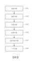
請參照圖1及3所示,為依據本發明實施例的一種用於積層製造的缺陷檢測方法,主要是透過一積層製造設備來實施,該用於積層製造的缺陷檢測方法包括一備置步驟S201、一鋪粉步驟S202、一取像步驟S203、一檢測步驟S204、一雷射熔融步驟S205以及一下移步驟S206。在本實施例中,該下移步驟S206係根據工件之切層厚度是否完成,若尚未完成則移至一鋪粉步驟S202持續進行相同步驟,直至工件完成列印為止。本發明將於下文詳細說明各步驟的關係及其運作原理。Please refer to FIGS. 1 and 3 , which is a defect detection method for additive manufacturing according to an embodiment of the present invention. It is mainly implemented through an additive manufacturing equipment. The defect detection method for additive manufacturing includes a preparation step S201 , a powder spreading step S202, an imaging step S203, a detection step S204, a laser melting step S205 and a moving step S206. In this embodiment, the moving down step S206 is based on whether the cutting thickness of the workpiece is completed. If it has not been completed, it moves to a powder spreading step S202 and continues to perform the same steps until the workpiece is completely printed. The present invention will describe the relationship between each step and its operating principle in detail below.
請參照圖1、2及3所示,在該備置步驟S201中,備置該積層製造設備,其中該積層製造設備包含一平台座2、一粉槽3、一刮刀4、一雷射掃描裝置5、一升降平台6、一取像裝置7以及一處理器8,該刮刀4配置為相對該平台座2移動,例如刮刀4方向往升降平台6左側移動,該刮刀4往該往升降平台6右側移動,另外,該雷射掃描裝置5以及該取像裝置7位於該平台座上方,該粉槽3、該刮刀4、該雷射掃描裝置5、該升降平台6及該取像裝置7電性連接該處理器8而且受到該處理器8控制,該升降平台6配置為驅動該平台座2升降。Please refer to Figures 1, 2 and 3. In the preparation step S201, the additive manufacturing equipment is prepared, wherein the additive manufacturing equipment includes a
要說明的是,該雷射掃描裝置5是透過高功率雷射照射,加熱一組成的金屬粉末至熔點以上,使得高密度金屬快速成型。在製程中需將雷射束同時照射金屬粉末與部份已成型的輪廓同時加熱過熔點,如此可在新、 舊成型區間形成橋狀連結以提高成型強度。在選擇性雷射熔融製程中,需通過惰性氣體流場與低氧環境以防止金屬氧化,同時,高成型溫度造成粉床與成型區 之間溫度梯度過大,元件容易因熔池固化時所形成的高殘留熱應力而發生斷裂、破損之現象。It should be noted that the
請參照圖1及3所示,在該鋪粉步驟S202中,移動該粉槽3對一鋪粉區域進行補粉,接著利用該刮刀4推抹該平台座2的粉料而形成一粉料層。Please refer to Figures 1 and 3. In the powder spreading step S202, the
請參照圖1、2及3所示,在該取像步驟S203中,利用該取像裝置7對該粉料層進行取像,以獲得一圖像,並且將該圖像傳送至該處理器8。Please refer to Figures 1, 2 and 3. In the imaging step S203, the
續參照圖1、2及3所示,在該檢測步驟S204中,由該處理器透過一演算法對該圖像進行分析,以判斷該圖像是否有缺陷,若該圖像有缺陷,則發出通知,若該圖像無缺陷,則進行下一步驟。Continuing to refer to Figures 1, 2 and 3, in the detection step S204, the processor analyzes the image through an algorithm to determine whether the image is defective. If the image is defective, then A notification is issued and if the image is not defective, proceed to the next step.
在該檢測步驟S204中,該演算法先篩選該圖像的多個候選物件,接著對該等候選物件尺寸統一,並且進行識別、分類、標示、定位以及影像分割。進一步來說,該演算法可以透過二種方式進行,其中一種是組合一階物件偵測網路以及物件分割網路對該圖像的該等候選物件進行分析,其中該一階物件偵測網路會先擷取該等候選物件的位置;另一種是組合二階物件偵測網路以及物件分割網路對該圖像的該等候選物件進行分析,其中該二階物件偵測網路會先識別該等候選物件的種類。In the detection step S204, the algorithm first screens multiple candidate objects in the image, then unifies the sizes of the candidate objects, and performs identification, classification, labelling, positioning and image segmentation. Furthermore, the algorithm can be performed in two ways, one of which is to combine a first-order object detection network and an object segmentation network to analyze the candidate objects of the image, where the first-order object detection network The path will first capture the positions of the candidate objects; the other is to combine a second-level object detection network and an object segmentation network to analyze the candidate objects in the image, in which the second-level object detection network will first identify The types of such candidate objects.
在本實施例中,該等候選物件具有介於0到1的一物件分數,該二階物件偵測網路依據該物件分數進行分析,該物件分數大於0.7的視為一物件,該物件分數小於0.3的視為一背景。另外,該物件分割網路配置為將該等候選物件經多層下採樣之後,再進行多層上採樣,以獲得影像分割的結果。在進行下採樣之前,該等候選物件的像素尺寸統一縮放為32x32或64x64。In this embodiment, the candidate objects have an object score between 0 and 1. The second-level object detection network performs analysis based on the object score. The object score greater than 0.7 is regarded as an object, and the object score less than 0.7 is regarded as an object. 0.3 is considered as a background. In addition, the object segmentation network is configured to perform multi-layer down-sampling on the candidate objects, and then perform multi-layer up-sampling to obtain image segmentation results. Before downsampling, the pixel dimensions of these candidate objects are uniformly scaled to 32x32 or 64x64.
進一步來說,在該備置步驟S201中,利用該處理器8接收多張訓練圖片,以對該演算法進行訓練參數調整,其中該等訓練圖片的種類包含鋪粉不均勻、鋪粉未覆蓋、刮刀刮痕以及正常影像。在本實施例中,該演算法的訓練參數透過對該圖像的缺陷的錨框尺度與錨框長寬比來進行調整。另外,在該檢測步驟S204中,該圖像的像素尺寸會先縮放為1024x1024。Furthermore, in the preparation step S201, the
請參照圖1及3所示,在該雷射熔融步驟S205中,利用該雷射掃描裝置5對該粉料層進行掃描熔融,以在該平台座2的一雷射加工區域成型一工件。Referring to FIGS. 1 and 3 , in the laser melting step S205 , the
續參照圖1及3所示,在該下移步驟S206,利用該升降平台6驅動該平台座2向下移動一距離,接著返回該鋪粉步驟S202,直到該工件完成。Continuing to refer to Figures 1 and 3, in the moving down step S206, the
要說明的是,在該演算法採用組合一階物件偵測網路以及物件分割網路中,是將原始資料集的圖像統一重新縮放成1024x1024的大小後,丟入已經訓練好的一階物件偵測網路(例如yolov4)中,藉此偵測出所有缺陷的所在位置。同時將yolov4偵測到的缺陷框擷取出圖像,並且重新縮放成32x32的尺寸大小,再丟入該物件分割網路(例如U-net)中。U-net共經過3次下採樣後,逐步進行上採樣處理,同時與下採樣的特徵串接,最後輸出32x32大小的影像分割的結果,最後將U-net的影像分割的結果與該圖像進行合成,就可以得到缺陷的位置。It should be noted that in this algorithm, which uses a combined first-order object detection network and an object segmentation network, the images in the original data set are uniformly rescaled to a size of 1024x1024, and then thrown into the already trained first-order In an object detection network (such as yolov4), the location of all defects can be detected. At the same time, the image of the defective frame detected by yolov4 is extracted, rescaled to a size of 32x32, and then thrown into the object segmentation network (such as U-net). After a total of 3 times of downsampling, U-net gradually performs upsampling processing, and at the same time is concatenated with the downsampled features, and finally outputs an image segmentation result of 32x32 size. Finally, the image segmentation result of U-net is combined with the image. Through synthesis, the location of the defect can be obtained.
在該演算法採用組合二階物件偵測網路以及物件分割網路中,該圖像輸入時會經過前處理並重新縮放到1024x1024,然後開始透過訓練好的二階物件偵測網路(Faster R-CNN)偵測出缺陷的所有位置,並把每個位置所涵蓋的該等候選物件重新縮到64x64,並且進入該物件分割網路(U-net)中,進而分割出缺陷大致上在矩形框內的分布,並且映射(map)到Faster R-CNN偵測出該圖像的矩形框實際的分布。In this algorithm, which uses a combined second-order object detection network and object segmentation network, the image input will be pre-processed and rescaled to 1024x1024, and then begin to pass through the trained second-order object detection network (Faster R- CNN) detects all positions of the defect, and re-shrinks the candidate objects covered by each position to 64x64, and enters the object segmentation network (U-net) to segment the defect roughly within the rectangular frame The distribution within the image is mapped to the actual distribution of the rectangular frame detected by Faster R-CNN.
如上所述,本發明用於積層製造的缺陷檢測方法主要是在鋪粉之後對該粉料層進行取像而獲得該圖像,並且利用演算法對該圖像進行分析,藉此使得該圖像的缺陷能夠進行分類、標示、定位與影像分割,以在鋪粉之後即時獲得該粉料層是否存在缺陷的資訊,提早對所檢出的缺陷採取因應措施,以避免缺陷(例如鋪粉不均勻、鋪粉未覆蓋、刮刀刮痕)所導致的製程卡刀中斷、工件廢棄及材料浪費的問題,減少瑕疵成品產出。As mentioned above, the defect detection method for multilayer manufacturing of the present invention mainly takes an image of the powder layer after spreading the powder to obtain the image, and uses an algorithm to analyze the image, thereby making the image Defects in the image can be classified, marked, positioned and image segmented, so that information on whether there are defects in the powder layer can be obtained immediately after the powder is spread, and corresponding measures can be taken early to detect the defects to avoid defects (such as incorrect powder spreading). Problems such as process interruption, workpiece abandonment and material waste caused by uniform powder spreading, uncovered powder coating, and scraper scratches, reduce the output of defective finished products.
雖然本發明已以實施例揭露,然其並非用以限制本發明,任何熟習此項技藝之人士,在不脫離本發明之精神和範圍內,當可作各種更動與修飾,因此本發明之保護範圍當視後附之申請專利範圍所界定者為準。Although the present invention has been disclosed through embodiments, they are not intended to limit the present invention. Any person skilled in the art can make various changes and modifications without departing from the spirit and scope of the present invention. Therefore, the protection of the present invention is The scope shall be determined by the appended patent application scope.
2:平台座 3:粉槽 4:刮刀 5:雷射掃描裝置 6:升降平台 7:取像裝置 8:處理器 S201:備置步驟 S202:鋪粉步驟 S203:取像步驟 S204:檢測步驟 S205:雷射熔融步驟 S206:下移步驟2: Platform seat 3:Powder trough 4:Scraper 5:Laser scanning device 6: Lifting platform 7: Imaging device 8: Processor S201: Preparation steps S202: Powder spreading step S203: Image acquisition step S204: Detection steps S205: Laser melting step S206: Move down step
圖1是依據本發明實施例的一種用於積層製造的缺陷檢測方法的積層製造設備的示意圖。 圖2是依據本發明實施例的一種用於積層製造的缺陷檢測方法的積層製造設備的各構件關係的示意圖。 圖3是依據本發明實施例的一種用於積層製造的缺陷檢測方法的流程圖。FIG. 1 is a schematic diagram of an additive manufacturing equipment used for a defect detection method in additive manufacturing according to an embodiment of the present invention. FIG. 2 is a schematic diagram of the relationship between various components of an additive manufacturing equipment according to a defect detection method for additive manufacturing according to an embodiment of the present invention. FIG. 3 is a flow chart of a defect detection method for additive manufacturing according to an embodiment of the present invention.
S201:備置步驟S201: Preparation steps
S202:鋪粉步驟S202: Powder spreading step
S203:取像步驟S203: Image acquisition step
S204:檢測步驟S204: Detection steps
S205:雷射熔融步驟S205: Laser melting step
S206:下移步驟S206: Move down step
Claims (10)
Translated fromChinesePriority Applications (1)
| Application Number | Priority Date | Filing Date | Title |
|---|---|---|---|
| TW111115536ATW202342201A (en) | 2022-04-22 | 2022-04-22 | Defect detection method for additive manufacturing |
Applications Claiming Priority (1)
| Application Number | Priority Date | Filing Date | Title |
|---|---|---|---|
| TW111115536ATW202342201A (en) | 2022-04-22 | 2022-04-22 | Defect detection method for additive manufacturing |
Publications (1)
| Publication Number | Publication Date |
|---|---|
| TW202342201Atrue TW202342201A (en) | 2023-11-01 |
Family
ID=89720515
Family Applications (1)
| Application Number | Title | Priority Date | Filing Date |
|---|---|---|---|
| TW111115536ATW202342201A (en) | 2022-04-22 | 2022-04-22 | Defect detection method for additive manufacturing |
Country Status (1)
| Country | Link |
|---|---|
| TW (1) | TW202342201A (en) |
Cited By (1)
| Publication number | Priority date | Publication date | Assignee | Title |
|---|---|---|---|---|
| CN118926551A (en)* | 2024-04-22 | 2024-11-12 | 华南理工大学 | A method for online monitoring and quality control of surface defects of parts in laser powder bed fusion process |
- 2022
- 2022-04-22TWTW111115536Apatent/TW202342201A/enunknown
Cited By (1)
| Publication number | Priority date | Publication date | Assignee | Title |
|---|---|---|---|---|
| CN118926551A (en)* | 2024-04-22 | 2024-11-12 | 华南理工大学 | A method for online monitoring and quality control of surface defects of parts in laser powder bed fusion process |
Similar Documents
| Publication | Publication Date | Title |
|---|---|---|
| CN107175329B (en) | A 3D printing device and method for layer-by-layer detection and reverse part model and defect location | |
| US10773336B2 (en) | Imaging devices for use with additive manufacturing systems and methods of monitoring and inspecting additive manufacturing components | |
| Yeung et al. | Part geometry and conduction-based laser power control for powder bed fusion additive manufacturing | |
| EP3536422B1 (en) | Detection and repair method for powder additive manufacturing | |
| US11806925B2 (en) | Additive manufacturing process | |
| JP6961926B2 (en) | Acoustic monitoring methods for additive manufacturing processes | |
| US9764517B2 (en) | Object production using an additive manufacturing process and quality assessment of the object | |
| JP6939082B2 (en) | Powder bed evaluation method | |
| CN207205270U (en) | A kind of 3D printing successively detects reverse part model and positioning defect device | |
| JP7318825B2 (en) | Laminate-molded article defect prediction method and laminate-molded article manufacturing method | |
| CN114450584B (en) | Layered Forming System | |
| WO2018080782A1 (en) | Imaging devices for use with additive manufacturing systems and methods of imaging a build layer | |
| CN106881462A (en) | A kind of on-line checking for selective laser fusing forming defects and optimization system | |
| CN118849429A (en) | Three-dimensional modeling object manufacturing device and structure manufacturing method | |
| CN110709194A (en) | Construction abnormality detection system for three-dimensional laminated molding device, construction abnormality detection method for three-dimensional laminated molding device, method for manufacturing three-dimensional laminated molded object, and three-dimensional laminated molded object | |
| US10821519B2 (en) | Laser shock peening within an additive manufacturing process | |
| CN116117169B (en) | A SLM process defect detection method and device | |
| CN113853272B (en) | Modeling system | |
| JP2019142184A (en) | Manufacturing system of addition molding and manufacturing method of addition molding | |
| GB2568536A (en) | Defect detection and correction | |
| TW202342201A (en) | Defect detection method for additive manufacturing | |
| CN113195130A (en) | Method for operating a production system and production system for additive production of components from powdered material | |
| US20210197282A1 (en) | Method and apparatus for estimating height of 3d printing object formed during 3d printing process, and 3d printing system having the same | |
| EP3991947A1 (en) | In-process optical based monitoring and control of additive manufacturing processes | |
| Wang et al. | Process parameters, product quality monitoring, and control of powder bed fusion |