TW202342159A - Organic solvent recovery system - Google Patents
Organic solvent recovery systemDownload PDFInfo
- Publication number
- TW202342159A TW202342159ATW112107689ATW112107689ATW202342159ATW 202342159 ATW202342159 ATW 202342159ATW 112107689 ATW112107689 ATW 112107689ATW 112107689 ATW112107689 ATW 112107689ATW 202342159 ATW202342159 ATW 202342159A
- Authority
- TW
- Taiwan
- Prior art keywords
- solvent
- dehydration
- treatment tank
- organic solvent
- gas
- Prior art date
Links
Images


Classifications
- B—PERFORMING OPERATIONS; TRANSPORTING
- B01—PHYSICAL OR CHEMICAL PROCESSES OR APPARATUS IN GENERAL
- B01D—SEPARATION
- B01D53/00—Separation of gases or vapours; Recovering vapours of volatile solvents from gases; Chemical or biological purification of waste gases, e.g. engine exhaust gases, smoke, fumes, flue gases, aerosols
- B01D53/34—Chemical or biological purification of waste gases
- B01D53/38—Removing components of undefined structure
- B01D53/44—Organic components
- B—PERFORMING OPERATIONS; TRANSPORTING
- B01—PHYSICAL OR CHEMICAL PROCESSES OR APPARATUS IN GENERAL
- B01D—SEPARATION
- B01D53/00—Separation of gases or vapours; Recovering vapours of volatile solvents from gases; Chemical or biological purification of waste gases, e.g. engine exhaust gases, smoke, fumes, flue gases, aerosols
- B01D53/02—Separation of gases or vapours; Recovering vapours of volatile solvents from gases; Chemical or biological purification of waste gases, e.g. engine exhaust gases, smoke, fumes, flue gases, aerosols by adsorption, e.g. preparative gas chromatography
- B01D53/04—Separation of gases or vapours; Recovering vapours of volatile solvents from gases; Chemical or biological purification of waste gases, e.g. engine exhaust gases, smoke, fumes, flue gases, aerosols by adsorption, e.g. preparative gas chromatography with stationary adsorbents
- B01D53/0454—Controlling adsorption
- B—PERFORMING OPERATIONS; TRANSPORTING
- B01—PHYSICAL OR CHEMICAL PROCESSES OR APPARATUS IN GENERAL
- B01D—SEPARATION
- B01D53/00—Separation of gases or vapours; Recovering vapours of volatile solvents from gases; Chemical or biological purification of waste gases, e.g. engine exhaust gases, smoke, fumes, flue gases, aerosols
- B01D53/02—Separation of gases or vapours; Recovering vapours of volatile solvents from gases; Chemical or biological purification of waste gases, e.g. engine exhaust gases, smoke, fumes, flue gases, aerosols by adsorption, e.g. preparative gas chromatography
- B01D53/04—Separation of gases or vapours; Recovering vapours of volatile solvents from gases; Chemical or biological purification of waste gases, e.g. engine exhaust gases, smoke, fumes, flue gases, aerosols by adsorption, e.g. preparative gas chromatography with stationary adsorbents
- B01D53/0407—Constructional details of adsorbing systems
- B01D53/0438—Cooling or heating systems
- B—PERFORMING OPERATIONS; TRANSPORTING
- B01—PHYSICAL OR CHEMICAL PROCESSES OR APPARATUS IN GENERAL
- B01D—SEPARATION
- B01D53/00—Separation of gases or vapours; Recovering vapours of volatile solvents from gases; Chemical or biological purification of waste gases, e.g. engine exhaust gases, smoke, fumes, flue gases, aerosols
- B01D53/14—Separation of gases or vapours; Recovering vapours of volatile solvents from gases; Chemical or biological purification of waste gases, e.g. engine exhaust gases, smoke, fumes, flue gases, aerosols by absorption
- B01D53/1425—Regeneration of liquid absorbents
- B—PERFORMING OPERATIONS; TRANSPORTING
- B01—PHYSICAL OR CHEMICAL PROCESSES OR APPARATUS IN GENERAL
- B01D—SEPARATION
- B01D53/00—Separation of gases or vapours; Recovering vapours of volatile solvents from gases; Chemical or biological purification of waste gases, e.g. engine exhaust gases, smoke, fumes, flue gases, aerosols
- B01D53/14—Separation of gases or vapours; Recovering vapours of volatile solvents from gases; Chemical or biological purification of waste gases, e.g. engine exhaust gases, smoke, fumes, flue gases, aerosols by absorption
- B01D53/1487—Removing organic compounds
- B—PERFORMING OPERATIONS; TRANSPORTING
- B01—PHYSICAL OR CHEMICAL PROCESSES OR APPARATUS IN GENERAL
- B01D—SEPARATION
- B01D53/00—Separation of gases or vapours; Recovering vapours of volatile solvents from gases; Chemical or biological purification of waste gases, e.g. engine exhaust gases, smoke, fumes, flue gases, aerosols
- B01D53/26—Drying gases or vapours
- B01D53/261—Drying gases or vapours by adsorption
- B—PERFORMING OPERATIONS; TRANSPORTING
- B01—PHYSICAL OR CHEMICAL PROCESSES OR APPARATUS IN GENERAL
- B01D—SEPARATION
- B01D53/00—Separation of gases or vapours; Recovering vapours of volatile solvents from gases; Chemical or biological purification of waste gases, e.g. engine exhaust gases, smoke, fumes, flue gases, aerosols
- B01D53/26—Drying gases or vapours
- B01D53/263—Drying gases or vapours by absorption
- B—PERFORMING OPERATIONS; TRANSPORTING
- B01—PHYSICAL OR CHEMICAL PROCESSES OR APPARATUS IN GENERAL
- B01D—SEPARATION
- B01D53/00—Separation of gases or vapours; Recovering vapours of volatile solvents from gases; Chemical or biological purification of waste gases, e.g. engine exhaust gases, smoke, fumes, flue gases, aerosols
- B01D53/34—Chemical or biological purification of waste gases
- B01D53/74—General processes for purification of waste gases; Apparatus or devices specially adapted therefor
- B01D53/81—Solid phase processes
- B01D53/82—Solid phase processes with stationary reactants
- B—PERFORMING OPERATIONS; TRANSPORTING
- B01—PHYSICAL OR CHEMICAL PROCESSES OR APPARATUS IN GENERAL
- B01D—SEPARATION
- B01D53/00—Separation of gases or vapours; Recovering vapours of volatile solvents from gases; Chemical or biological purification of waste gases, e.g. engine exhaust gases, smoke, fumes, flue gases, aerosols
- B01D53/34—Chemical or biological purification of waste gases
- B01D53/96—Regeneration, reactivation or recycling of reactants
- B—PERFORMING OPERATIONS; TRANSPORTING
- B01—PHYSICAL OR CHEMICAL PROCESSES OR APPARATUS IN GENERAL
- B01D—SEPARATION
- B01D2253/00—Adsorbents used in seperation treatment of gases and vapours
- B01D2253/10—Inorganic adsorbents
- B01D2253/102—Carbon
- B—PERFORMING OPERATIONS; TRANSPORTING
- B01—PHYSICAL OR CHEMICAL PROCESSES OR APPARATUS IN GENERAL
- B01D—SEPARATION
- B01D2257/00—Components to be removed
- B01D2257/70—Organic compounds not provided for in groups B01D2257/00 - B01D2257/602
- B01D2257/704—Solvents not covered by groups B01D2257/702 - B01D2257/7027
- B—PERFORMING OPERATIONS; TRANSPORTING
- B01—PHYSICAL OR CHEMICAL PROCESSES OR APPARATUS IN GENERAL
- B01D—SEPARATION
- B01D2257/00—Components to be removed
- B01D2257/80—Water
Landscapes
- Chemical & Material Sciences (AREA)
- Engineering & Computer Science (AREA)
- Analytical Chemistry (AREA)
- General Chemical & Material Sciences (AREA)
- Oil, Petroleum & Natural Gas (AREA)
- Chemical Kinetics & Catalysis (AREA)
- Environmental & Geological Engineering (AREA)
- Health & Medical Sciences (AREA)
- Biomedical Technology (AREA)
- Life Sciences & Earth Sciences (AREA)
- Sustainable Development (AREA)
- Treating Waste Gases (AREA)
- Vaporization, Distillation, Condensation, Sublimation, And Cold Traps (AREA)
Abstract
Translated fromChineseDescription
Translated fromChinese本發明係關於有機溶劑回收系統。The present invention relates to an organic solvent recovery system.
有機溶劑回收系統設置有以吸附材將被處理氣體的有機溶劑吸附之一對處理槽、對各處理槽進行供給之被處理氣體供給裝置、以及脫附用氣體供給裝置,並採用了在對處理槽供給被處理氣體的吸附步驟與供給脫附用氣體的脫附步驟間進行切換的機構。The organic solvent recovery system is equipped with a pair of treatment tanks that use an adsorbent to adsorb the organic solvent of the gas to be processed, a gas supply device to be processed that supplies each treatment tank, and a gas supply device for desorption, and adopts a pair of treatment tanks. The tank is a mechanism for switching between the adsorption step of supplying the gas to be processed and the desorption step of supplying the desorption gas.
作為氣體處理裝置的吸附材,已有人使用了例如活性碳纖維(Activated Carbon Fiber(ACF),以下記載為ACF)。ACF在吸附低濃度的含有機溶劑氣體之功能方面優越,而被使用作為吸附材。例如,在日本特開2014-147864號公報(專利文獻1)揭示了,將ACF固定於支撐體、或是藉由自支撐而構成圓筒狀,並直立地配置在芯材內的氣體處理裝置。 [先前技術文獻] [專利文獻]As an adsorbent material for a gas treatment device, for example, activated carbon fiber (Activated Carbon Fiber (ACF), hereafter referred to as ACF) has been used. ACF is used as an adsorbent material because of its superior ability to adsorb low-concentration gases containing organic solvents. For example, Japanese Patent Application Laid-Open No. 2014-147864 (Patent Document 1) discloses a gas treatment device in which the ACF is fixed to a support or formed into a cylindrical shape by self-supporting, and is arranged upright in a core material. . [Prior technical literature] [Patent Document]
[專利文獻1]日本特開2014-147864號公報[Patent Document 1] Japanese Patent Application Publication No. 2014-147864
[發明所欲解決之問題][The problem that the invention aims to solve]
從吸附材回收後的回收溶劑有時含有水分。在將回收溶劑再利用於生產設備的情況下,有必要進行回收溶劑的脫水(去除水分)。關於其手段,已知使回收溶劑接觸於沸石等脫水材而使其脫水的技術。藉由令回收溶劑通過具有填充了脫水材的脫水處理槽的脫水裝置,而進行自回收溶劑脫水的操作。The recovered solvent recovered from the adsorbent material may contain moisture. When the recovered solvent is reused in production equipment, it is necessary to dehydrate (remove water) the recovered solvent. As a means for this, a technique is known in which the recovery solvent is brought into contact with a dewatering material such as zeolite to dehydrate the solvent. The operation of dehydrating the recovered solvent is performed by passing the recovered solvent through a dehydration device having a dehydration treatment tank filled with a dewatering material.
然而,在脫水裝置停止、被處理氣體中的有機溶劑負載量比設計少的情況下,有時回收溶劑長時間持續滯留在脫水處理槽內。在此情況下,由於來自脫水處理槽內的脫水材之水的脫附,故水會返回到回收溶劑,而存在有於脫水裝置再運轉時須將水分去除不充分的脫水溶劑排出之課題。其他的課題,還有因為脫水處理槽內所含有的有機溶劑通過脫水裝置的配管出口揮發,使得有機溶劑的回收量降低的課題。However, when the dehydration device is stopped and the organic solvent loading amount in the gas to be processed is less than designed, the recovered solvent may remain in the dehydration treatment tank for a long time. In this case, due to the desorption of water from the dewatered material in the dehydration treatment tank, the water returns to the recovery solvent, and there is a problem that the dehydration solvent with insufficient water removal must be discharged when the dehydration device is restarted. Another problem is that the organic solvent contained in the dehydration treatment tank volatilizes through the piping outlet of the dehydration device, thereby reducing the recovery amount of the organic solvent.
本發明係在於解決上述課題;第一個目的,係在於提供即使是再運轉時亦能排出被充分地去除水分後的脫水溶劑的有機溶劑回收系統。再者,第二個目的,係在於提供能抑制脫水處理槽內所含有的有機溶劑通過脫水裝置的配管出口而揮發,而抑制有機溶劑的回收量的降低之有機溶劑回收系統。 [解決問題之技術手段]The present invention is to solve the above-mentioned problems; the first object is to provide an organic solvent recovery system that can discharge the dehydration solvent from which water has been sufficiently removed even during re-operation. Furthermore, the second object is to provide an organic solvent recovery system that can suppress the organic solvent contained in the dehydration treatment tank from volatilizing through the piping outlet of the dehydration device, thereby suppressing a decrease in the recovery amount of the organic solvent. [Technical means to solve problems]
在本發明的有機溶劑回收系統,係一種具備回收裝置、脫水裝置、以及回送裝置之有機溶劑回收系統,且具備以下的構成。The organic solvent recovery system of the present invention is an organic solvent recovery system including a recovery device, a dehydration device, and a return device, and has the following configuration.
上述回收裝置包含:吸附材,藉由與含有難溶於水且比重大於水的有機溶劑之被處理氣體接觸,而將上述有機溶劑吸附,並藉由與水蒸氣接觸而使上述有機溶劑脫附;兩個以上的處理槽,收納了上述吸附材;向上述處理槽供給上述被處理氣體,並在上述吸附材將上述有機溶劑吸附去除,而將清淨氣體排出之吸附步驟;向上述處理槽供給水蒸氣,而使回收溶劑從上述吸附材脫附,並將脫附氣體排出之脫附步驟;對兩個以上的上述處理槽,依次反覆進行上述吸附步驟與上述脫附步驟之步驟;凝結器,使上述脫附氣體冷卻凝結並將脫附液排出;以及分離器,將上述脫附液分離成分離水的層與上述回收溶劑的層。The above-mentioned recovery device includes: an adsorbent material, which adsorbs the organic solvent by contacting with the gas to be processed containing an organic solvent that is poorly soluble in water and has a specific gravity greater than water, and desorbs the organic solvent by contacting with water vapor. ; Two or more treatment tanks accommodate the adsorbent material; an adsorption step of supplying the gas to be processed to the treatment tank, adsorbing and removing the organic solvent on the adsorbent material, and discharging the clean gas; supplying the gas to the treatment tank water vapor to desorb the recovered solvent from the above-mentioned adsorbent material and discharge the desorbed gas; perform the above-mentioned adsorption step and the above-mentioned desorption step repeatedly for two or more above-mentioned treatment tanks; condenser , cooling and condensing the desorbed gas and discharging the desorbed liquid; and a separator that separates the desorbed liquid into a layer for separating water and a layer for recovering the solvent.
上述脫水裝置包含:脫水材,藉由與上述回收溶劑接觸,而將上述回收溶劑所含有的水分吸附;一個以上的脫水處理槽,收納了上述脫水材;以及排出機構,向上述脫水處理槽供給藉由上述分離器分離後的上述回收溶劑,並將藉由上述脫水材而被從上述回收溶劑脫水後的脫水溶劑,從上述脫水處理槽排出。The above-mentioned dehydration device includes: a dehydration material that contacts the above-mentioned recovery solvent to adsorb the moisture contained in the above-mentioned recovery solvent; one or more dehydration treatment tanks that accommodate the above-mentioned dehydration treatment material; and a discharge mechanism that supplies the above-mentioned dehydration treatment tank. The recovery solvent separated by the separator and the dehydration solvent dehydrated from the recovery solvent by the dehydration material are discharged from the dehydration treatment tank.
上述回送裝置,在將上述脫水處理槽內的上述回收溶劑向上述分離器回送的時候,將上述回收溶劑送入至上述分離器之上述回收溶劑的層。The return device sends the recovered solvent into the recovered solvent layer of the separator when returning the recovered solvent in the dehydration treatment tank to the separator.
在上述之有機溶劑回收系統中,上述回送裝置具有:回送流道,在上述脫水裝置停止了向上述脫水處理槽供給上述回收溶劑的情況下,使上述回收溶劑向上述脫水處理槽之外排出,並使上述回收溶劑向上述分離器回送。In the above-mentioned organic solvent recovery system, the return device has a return flow channel, and when the dehydration device stops supplying the recovery solvent to the dehydration treatment tank, the recovery solvent is discharged to the outside of the dehydration treatment tank, And the above-mentioned recovered solvent is returned to the above-mentioned separator.
在上述之有機溶劑回收系統中,上述脫水裝置更包含:速度調整裝置,調整向上述分離器回送之上述回收溶劑的速度。In the above-mentioned organic solvent recovery system, the above-mentioned dehydration device further includes: a speed adjustment device to adjust the speed of the above-mentioned recovered solvent returned to the above-mentioned separator.
在上述之有機溶劑回收系統中,上述速度調整裝置,利用上述被處理氣體、或是上述清淨氣體的一部分,將上述脫水處理槽的內部加壓,而使上述回收溶劑向上述脫水處理槽之外排出。In the above-mentioned organic solvent recovery system, the above-mentioned speed adjustment device uses the above-mentioned gas to be processed or a part of the above-mentioned clean gas to pressurize the inside of the above-mentioned dehydration treatment tank, so that the above-mentioned recovered solvent flows out of the above-mentioned dehydration treatment tank. discharge.
在上述之有機溶劑回收系統中,具有:三個以上的上述處理槽;且藉由其中一個上述處理槽進行上述脫附步驟,而其餘的上述處理槽係多段串聯連接並進行上述吸附步驟。 [發明之功效]In the above-mentioned organic solvent recovery system, there are: three or more above-mentioned treatment tanks; and the above-mentioned desorption step is performed by one of the above-mentioned treatment tanks, while the remaining above-mentioned treatment tanks are connected in series in multiple stages and perform the above-mentioned adsorption step. [The effect of invention]
根據本發明,能夠提供即使是再運轉時亦能排出被充分地去除水分後的脫水溶劑的有機溶劑回收系統。更佳為,能夠提供能抑制脫水處理槽內所含有的有機溶劑通過脫水裝置的配管出口而揮發,而抑制有機溶劑的回收量的降低的有機溶劑回收系統。According to the present invention, it is possible to provide an organic solvent recovery system that can discharge the dehydration solvent from which water has been sufficiently removed even during re-operation. More preferably, it is possible to provide an organic solvent recovery system that can suppress the organic solvent contained in the dehydration treatment tank from volatilizing through the piping outlet of the dehydration device, thereby suppressing a decrease in the amount of recovered organic solvent.
關於基於本發明之各實施態樣的有機溶劑回收系統,以下一面參照圖式一面進行說明。在以下所說明之實施態樣中,在提及個數、量等的情況下,除了有特別記載的情況外,本發明的範圍並不一定限於其個數、量等。對於相同的元件、相當的元件,有時會賦予相同的參照號碼,而不再度重複說明。此外,自一開始便已預計將實施態樣中的構成適當地搭配組合使用。The organic solvent recovery system according to each embodiment of the present invention will be described below with reference to the drawings. In the embodiments described below, when the number, quantity, etc. are mentioned, the scope of the present invention is not necessarily limited to the number, quantity, etc., unless otherwise specified. The same components or equivalent components may be given the same reference numbers without repeated description. Furthermore, it has been anticipated from the outset that components in the implementation will be used in appropriate combinations.
在本發明中使用的有機溶劑表示難溶於水且比重大於水的有機溶劑。具體而言係指:1,2,4-三氯苯、1,1,1-三氯乙烷、三氯乙烯、全氯乙烯、二氯甲烷、四氯化碳、氯仿、氯化乙烯、碳酸二甲酯、1-溴丙烷、鄰二氯苯、硝基苯、1,2-二氯丙烷、環氧氯丙烷、一氯苯、1,2-二氯乙烷、1,1,2-三氯乙烷、1,2-二氯乙烯、1,1,2-三氯乙烷、1,1,2,2-四氯乙烷、五氯乙烷、1,1-二氯乙烯、溴化甲烷,還有氟龍11(一氟三氯甲烷)、氟龍12(二氟二氯甲烷)、氟龍225(二氯五氟丙烷)、十氟戊烷、乙基九氟丁基醚等氫氟碳化物類等。亦可處理此處所列舉以外的有機溶劑。The organic solvent used in the present invention means an organic solvent that is poorly soluble in water and has a specific gravity greater than that of water. Specifically, it refers to: 1,2,4-trichlorobenzene, 1,1,1-trichloroethane, trichloroethylene, perchlorethylene, methylene chloride, carbon tetrachloride, chloroform, chlorinated ethylene, Dimethyl carbonate, 1-bromopropane, o-dichlorobenzene, nitrobenzene, 1,2-dichloropropane, epichlorohydrin, monochlorobenzene, 1,2-dichloroethane, 1,1,2 -Trichloroethane, 1,2-dichloroethane, 1,1,2-trichloroethane, 1,1,2,2-tetrachloroethane, pentachloroethane, 1,1-dichloroethane , methyl bromide, as well as fluoron 11 (monofluorotrichloromethane), fluoron 12 (difluorodichloromethane), fluoron 225 (dichloropentafluoropropane), decafluoropentane, ethyl nonafluorobutane Hydrofluorocarbons such as base ethers, etc. Organic solvents other than those listed here can also be processed.
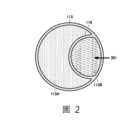
[實施態樣1:有機溶劑回收系統1000] 參照圖1及圖2,針對本實施態樣之有機溶劑回收系統1000加以說明。圖1係表示有機溶劑回收系統1000的構成之圖式,圖2係圖1中II-II線處依箭頭方向觀察的剖面圖。[Implementation 1: Organic solvent recovery system 1000] Referring to FIGS. 1 and 2 , the organic
此有機溶劑回收系統1000具備:回收裝置1、脫水裝置2、以及回送裝置3。以下,針對該等各個裝置的詳細構成加以說明。This organic
(回收裝置1) 回收裝置1具備第一處理槽104A以及第二處理槽104B。第一處理槽104A包含圓筒狀的第一吸附材105A;第二處理槽104B包含圓筒狀的第二吸附材105B。第一吸附材105A及第二吸附材105B,係被處理氣體A從其外側向內側通過而實施吸附步驟,而水蒸氣則從其內側向外側通過以實施脫附步驟。於第一吸附材105A及第二吸附材105B使用了例如ACF。(Recycling device 1) The recovery device 1 includes a
第一處理槽104A及第二處理槽104B係與被處理氣體導入管線103及脫附氣體管線110連通著。為了進行向被處理氣體導入管線103的連通之開閉,以及向脫附氣體管線110的連通之開閉,在第一處理槽104A及第二處理槽104B,分別設置了第一自動下閘板107A及第二自動下閘板107B。The
在第一處理槽104A及第二處理槽104B的上方,分別設置了控制被處理氣體A的流通的第一自動上閘板106A及第二自動上閘板106B。Above the
在脫附氣體管線110連結了凝結器111。凝結器111具有:脫附氣體管線110所連結的凝結器入口111B,以及脫附液管線112所連結的凝結器出口111C。在凝結器111的內部,收納了具有冷卻水入口111E及冷卻水出口111F的冷卻水配管111A。A
在連結於凝結器出口111C的脫附液管線112,連結有分離器113。分離器113將從脫附液管線112送達的脫附液分離成分離水113A的層與回收溶劑113B的層。關於分離水113A,採用在藉由曝氣裝置曝氣後排水之構成即可(參照圖6的有機溶劑回收系統1000D的曝氣裝置800)。A
此處,將分離水113A以曝氣裝置曝氣後排水之構成係指例如,藉由一面將分離水113A加溫一面進行通氣處理,使分離水113A中的有機溶劑氣化而去除。藉由與本實施態樣的有機溶劑回收系統1000搭配組合,能夠將分離水113A中的有機溶劑去除而淨化。Here, the structure in which the
由於在被處理氣體A使用了難溶於水且比重大於水的有機溶劑,故在分離器113的內部,回收溶劑113B滯留於下層,而分離水113A滯留於上層。藉此,回收溶劑113B藉由分離水113A而成為被蓋住的狀態,而抑制回收溶劑113B向系統外揮發。在分離器113內,設置有偵測回收溶劑113B層的液面位置之回收溶劑液面監視裝置115。Since an organic solvent that is poorly soluble in water and has a specific gravity greater than water is used for the gas to be processed A, the recovered
在凝結器111的返回氣體出口111D以及分離器113的氣相區域113D,連結了返回氣體管線114。返回氣體管線114係被導入至被處理氣體管線101。從返回氣體管線114回送至被處理氣體管線101的氣體,以相對於被處理氣體A的流動方向成為對向流的方式導入即可。A
在被處理氣體管線101設置有被處理氣體送風機102。藉由被處理氣體送風機102送出的被處理氣體A,通過被處理氣體導入管線103,而送入第一處理槽104A及第二處理槽104B。The gas to be processed
水蒸氣C係通過水蒸氣管線108而被供給至第一處理槽104A及第二處理槽104B。第一處理槽104A係與水蒸氣管線108連通,且於水蒸氣管線108設置有第一水蒸氣開關閥109A。第二處理槽104B係與水蒸氣管線108連通,且於水蒸氣管線108設置有第二蒸氣開關閥109B。The water vapor C is supplied to the
在具有上述構成的回收裝置1中,第一自動上閘板106A、第二自動上閘板106B、第一自動下閘板107A、第二自動下閘板107B、第一水蒸氣開關閥109A、第二蒸氣開關閥109B、凝結器111、分離器113、回收溶劑液面監視裝置115、及被處理氣體送風機102,係藉由未圖示之控制裝置來適當控制其運作及開閉,俾實現以下所示之氣體處理方法。In the recovery device 1 having the above structure, the first automatic
(氣體處理方法) 針對使用了具有上述構成的回收裝置1之氣體處理方法加以說明。在圖1中,回收裝置1的第一處理槽104A實施脫附步驟,而第二處理槽104B實施吸附步驟。(Gas treatment method) A gas treatment method using the recovery device 1 having the above configuration will be described. In FIG. 1 , the
(第二處理槽104B的吸附步驟) 含有含有機溶劑氣體之被處理氣體A,從被處理氣體管線101,藉由被處理氣體送風機102而送至進行吸附步驟的第二處理槽104B。第二自動下閘板107B係以將被處理氣體導入管線103開啟,並將脫附氣體管線110封閉的方式受到控制。(Adsorption step of
第二自動上閘板106B係被控制成:使被處理氣體A能夠在第二吸附材105B流通的開啟狀態。The second automatic
在第二處理槽104B的第二吸附材105B進行氣體吸附,而作為清淨氣體B向系統外導出。水蒸氣管線108的第二蒸氣開關閥109B係被控制為關閉狀態。The gas is adsorbed on the
(第一處理槽104A的脫附步驟) 對於第一處理槽104A,並不送入被處理氣體A,而係藉由第一自動下閘板107A,控制成將被處理氣體導入管線103封閉並將脫附氣體管線110開啟之狀態。第一自動下閘板107A,封閉從第一吸附材105A的外側向內側之氣體的流通。脫附用的水蒸氣C,通過水蒸氣管線108,以能夠從第一吸附材105A的內側向外側流通的方式被導入。水蒸氣管線108的第一水蒸氣開關閥109A係被控制成開啟狀態。(Desorption step of
在第一處理槽104A內,水蒸氣噴出,而吸附於第一吸附材105A之有機溶劑從第一吸附材105A脫附。含有脫附後的有機溶劑之脫附氣體G通過脫附氣體管線110而被送往凝結器111。In the
脫附後的脫附氣體G及水蒸氣C,在凝結器111受到凝結。含有高濃度的有機溶劑之脫附液,通過脫附液管線112而被送往分離器113。脫附液在分離器113分離成分離水113A的層與回收溶劑113B的層。在分離器113的內部,如上述般,回收溶劑113B滯留於下層,而分離水113A滯留於上層。The desorbed gas G and water vapor C are condensed in the
滯留在凝結器111及分離器113內的返回氣體J,係藉由脫附氣體G而被擠出,並通過返回氣體管線114而導入被處理氣體管線101,而混合於被處理氣體A。從被處理氣體管線101導入的被處理氣體A以及返回氣體J,被送至第二處理槽104B。The return gas J retained in the
將以上步驟反覆進行,而從連結於分離器113的回收溶劑113B的層之回收溶劑管線210,將回收溶劑113B送入脫水裝置2。The above steps are repeated, and the recovered solvent 113B is sent to the
一旦經過規定的時間,吸附步驟與脫附步驟即改換,第一處理槽104A變為吸附步驟,而第二處理槽104B變為脫附步驟。如此般,藉由交替進行吸附步驟與脫附步驟之連續的處理,而藉由回收裝置1連續地將回收溶劑113B回收。Once a predetermined time has passed, the adsorption step and the desorption step are switched, and the
(脫水裝置2) 接著,在脫水裝置2進行對藉由上述回收裝置1所回收的回收溶劑113B的脫水處理。以下針對脫水裝置2的構成進行說明。脫水裝置2具備:藉由與由分離器113所分離後的回收溶劑113B接觸,而將回收溶劑113B所含有的水分吸附之脫水材202,以及收納此脫水材202的脫水處理槽203。於脫水材202,使用了例如沸石等。又,亦可使用活性氧化鋁、離子交換樹脂、活性碳等。(Dehydration device 2) Next, the dehydration process of the recovery solvent 113B recovered by the recovery device 1 is performed in the
分離器113與脫水處理槽203之間係藉由回收溶劑管線210而連通著。回收溶劑管線210的一端係連結於藉由分離器113分離後的回收溶劑113B的槽。回收溶劑管線210的另一端係連結於脫水處理槽203的下端。The
在回收溶劑管線210的中途區域設置有泵浦201。藉由泵浦201而將回收溶劑113B送入脫水處理槽203。在泵浦201的下游側的回收溶劑管線210,設置有逆止閥205。藉由逆止閥205,來阻止回收溶劑113B之從脫水處理槽203向泵浦201側的逆流。A
在脫水處理槽203的上部設置了脫水溶劑排出管線113C。在脫水溶劑排出管線113C設置了脫水溶劑閥401。再者,在脫水溶劑閥401連結有能導入既定氣體F的流量調整閥402。泵浦201、脫水溶劑閥401、以及流量調整閥402,係藉由未圖示的控制裝置來適當控制其運作及開閉,俾實現以下所示之脫水處理。A dehydration
(脫水處理) 藉由泵浦201的運轉而被從脫水處理槽203的下方側送入的回收溶劑113B,經由與脫水材202接觸而被脫水,而作為脫水溶劑E,從脫水溶劑排出管線113C排出至系統外。至少,回收溶劑管線210、泵浦201、脫水溶劑閥401、以及脫水溶劑排出管線113C,構成將脫水溶劑E從脫水處理槽203排出之排出機構。(dehydration treatment) The recovered solvent 113B sent from the lower side of the
(回送裝置3) 在上述脫水裝置2停止的情況下,或是被處理氣體中的有機溶劑負載量較設計少的情況下,在上述脫水處理槽203內回收溶劑113B會長時間持續滯留。此時,由於水從脫水處理槽203內的脫水材202脫附,故會有水返回到回收溶劑113B,而在脫水裝置2再運轉時將水分去除不充分的脫水溶劑E排出之虞。再者,亦有因脫水處理槽203內所含有的有機溶劑通過脫水裝置2的配管出口揮發,而使有機溶劑的回收量降低之虞。(Loopback device 3) When the
於是,回送裝置3在脫水裝置2停止的情況下,或是被處理氣體中的有機溶劑負載量較設計少的情況下,實施將脫水處理槽203內的回收溶劑113B往分離器113回送之運作。具體而言,回送裝置3具備:將回收溶劑113B往分離器113的回收溶劑113B的層回送之構成。Therefore, the return device 3 performs an operation of returning the recovered solvent 113B in the
參照圖2,在本實施態樣的分離器113內,設置有隔板116。隔板116,構成上下端在分離器113的內部空間開放之獨立的空間。隔板116的下端係到達至回收溶劑113B的槽。隔板116的上端係開放於氣相區域113D的構成。在使有機溶劑回收系統1000運作之時,有需要在分離器113的內部預先積存好既定量的回收溶劑113B至超過隔板116的下端的高度。Referring to FIG. 2 , a
再次參照圖1,在與脫水處理槽203連通之回收溶劑管線210的逆止閥205的下游側,設置有從回收溶劑管線210分岐之回送管線301。此回送管線301,係在脫水裝置2停止向脫水處理槽203之回收溶劑113B的供給等情況下,令回收溶劑113B向脫水處理槽203外排出,而使回收溶劑113B往分離器113回送之流道。在回送管線301設置有開關閥302。Referring again to FIG. 1 , a
開關閥302、脫水溶劑閥401、以及流量調整閥402,係由未圖示之控制裝置來適當控制其運作及開閉,俾實現以下所示之將脫水處理槽203內的回收溶劑113B向分離器113回送之回送處理。The operation and opening and closing of the
(回收溶劑113B的回送處理) 在使回收溶劑113B向脫水處理槽203外排出的情況,係以將開關閥302開放並將脫水溶劑閥401關閉的狀態,從流量調整閥402將既定氣體F導入。藉此,能將脫水處理槽203的內壓加壓,而使殘存於脫水處理槽203的內部之回收溶劑113B向分離器113回送。(Return processing of recovered solvent 113B) When the recovered solvent 113B is discharged to the outside of the
此處,作為既定氣體F,亦可使用外部氣體,但使用例如被處理氣體A、或是清淨氣體B即可。又,藉由以流量調整閥402來控制這些氣體的送入量及送入速度,能避免一口氣將氣體導入,而緩緩地使氣體導入。藉此,便可調整向分離器113回送的回收溶劑113B的送入量及送入速度。其結果,能將被處理氣體A所包含的有機溶劑有效率地回收。尤其,在有機溶劑昂貴的情況下,其經濟上的效果很大。Here, as the predetermined gas F, external gas may also be used, but for example, the gas to be processed A or the clean gas B may be used. Furthermore, by controlling the feed amount and feed speed of these gases with the flow
向分離器113回送的回收溶劑113B,被送入分離器113內以隔板116所分隔的空間。藉此,向分離器113回送的回收溶劑113B,直接被送回到分離器113內的回收溶劑113B的層。因此,不會再次與分離水113A混合。The recovered solvent 113B returned to the
如此般,依本實施態樣之有機溶劑回收系統1000,為了避免在脫水裝置2停止的情況下、或是被處理氣體A中的有機溶劑負載量較設計少的情況下,回收溶劑113B在脫水處理槽203內長時間持續滯留,而如上述般進行將脫水處理槽203內的回收溶劑113B向分離器113回送之運作控制。In this way, according to the organic
藉此,便能夠即使在藉由有機溶劑回收系統1000進行脫水裝置2的再運轉時,亦將被充分地去除水分後的脫水溶劑E排出至系統外。再者,能抑制脫水處理槽203內所包含的有機溶劑通過脫水裝置2的配管出口而揮發。藉此,以有機溶劑回收系統1000整體而言,能期待有機溶劑的回收之改善。Thereby, even when the
在脫水裝置2停止(泵浦201停止)後,將脫水處理槽203的出入口以閥體等使其全關閉,亦可避免回收溶劑113B在脫水處理槽203內長時間持續滯留。然而,若回收溶劑113B的一部分因外界氣溫等而在脫水處理槽203內揮發的話,則有可能內壓會升高。再者,若在脫水處理槽203內長時間持續保持回收溶劑113B的話,亦有可能被脫水出來的水會從脫水材202脫附。因此,較佳係如在上述實施態樣所示般,進行將脫水處理槽203內的回收溶劑113B向分離器113回送之運作控制。After the
又,亦可採用包含「將分離器113、脫水裝置2、回送裝置3、脫水處理槽203的任一者以上之內部所含有的回收溶劑113B調整成既定溫度之溫調機構」的構成。Alternatively, a structure including "a temperature adjustment mechanism for adjusting the recovered solvent 113B contained in any one or more of the
[實施態樣2:有機溶劑回收系統1000A] 參照圖3,針對本實施態樣之有機溶劑回收系統1000A加以說明。圖3係表示有機溶劑回收系統1000A的構成之圖式。[Implementation 2: Organic
有機溶劑回收系統1000A之基本的構成與在上述實施態樣1所說明之有機溶劑回收系統1000相同。相異點在脫水裝置2的構成。本實施態樣的脫水裝置2中,在脫水處理槽203,回收溶劑管線210係被連結於脫水處理槽203的上側,而脫水溶劑排出管線113C則被連結於脫水處理槽203的下側。因此,回收溶劑113B變為從上方朝向下方流動。The basic structure of the organic
依此構成亦能得到與上述實施態樣1之有機溶劑回收系統1000相同的作用效果。With this configuration, the same effects as those of the organic
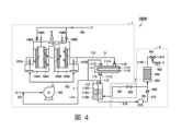
[實施態樣3:有機溶劑回收系統1000B] 參照圖4,針對本實施態樣之有機溶劑回收系統1000B加以說明。圖4係表示有機溶劑回收系統1000B的構成之圖式。[Implementation 3: Organic
有機溶劑回收系統1000B之基本的構成與在上述實施態樣1所說明之有機溶劑回收系統1000相同。相異點在分離器113的構成。在本實施態樣中的分離器113,未設置有隔板116,而係直接連接在分離器113之回收溶劑113B的槽。The basic structure of the organic
依此構成亦能得到與上述實施態樣1之有機溶劑回收系統1000相同的作用效果。With this configuration, the same effects as those of the organic
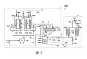
[實施態樣4:有機溶劑回收系統1000C] 參照圖5,針對本實施態樣之有機溶劑回收系統1000C加以說明。圖5係表示有機溶劑回收系統1000C的構成之圖式。[Implementation 4: Organic
有機溶劑回收系統1000C之基本的構成,與在上述實施態樣1所說明之有機溶劑回收系統1000相同。相異點係在脫水裝置2的構成中,設置了第一脫水處理槽203A及第二脫水處理槽203B作為脫水處理槽。藉由在進行其中一個處理槽之脫水材202的處理的期間,使另一個脫水處理槽運轉,而能連續地使脫水裝置2運轉。The basic structure of the organic
依此構成亦能得到與上述實施態樣1之有機溶劑回收系統1000相同的作用效果。With this configuration, the same effects as those of the organic
應了解到,本次所揭示之實施態樣在所有方面上皆為例示而非限制性者。本發明的範圍並非上述之說明,而係由申請專利範圍所表示,並意指包含在與申請專利範圍均等的意義及範圍內之所有變更。It should be understood that the implementation modes disclosed this time are illustrative and not restrictive in all respects. The scope of the present invention is shown not by the above description but by the claimed scope, and is intended to include all changes within the meaning and scope that are equivalent to the claimed scope.
在上述揭示內容的回收裝置1中,針對使用第一處理槽104A及第二處理槽104B作為處理槽,而交互進行吸附步驟與脫附步驟之有機溶劑的回收處理進行了說明,但並不限於此使用兩個處理槽之回收處理。In the recovery device 1 disclosed above, the organic solvent recovery process in which the
例如,亦可如圖7所示般,作為實施態樣1之有機溶劑回收系統1000的變形例,如日本特開2014-147863號公報所揭示般,採用「第一處理槽104A、第二處理槽104B、及第三處理槽104C三個處理槽,並藉由其中一個該處理槽進行脫附步驟,而其餘的處理槽係多段串聯連接並進行吸附步驟」的有機溶劑回收系統1000E。在圖7中,省略了脫水裝置2及回送裝置3、凝結器111、以及分離器113的圖示。又,處理槽亦可為三個以上。藉此,便能更提高有機溶劑的回收效率。For example, as shown in FIG. 7 , as a modification of the organic
1:回收裝置 2:脫水裝置 3:回送裝置 101:被處理氣體管線 102:被處理氣體送風機 103:被處理氣體導入管線 104A:第一處理槽 104B:第二處理槽 104C:第三處理槽 105A:第一吸附材 105B:第二吸附材 105C:第三吸附材 106A:第一自動上閘板 106B:第二自動上閘板 106C:第三自動上閘板 107A:第一自動下閘板 107B:第二自動下閘板 107C:第三自動下閘板 108:水蒸氣管線 109A:第一水蒸氣開關閥 109B:第二蒸氣開關閥 110:脫附氣體管線 111:凝結器 111A:冷卻水配管 111B:凝結器入口 111C:凝結器出口 111D:氣體出口(返回氣體出口) 111E:冷卻水入口 111F:冷卻水出口 112:脫附液管線 113:分離器 113A:分離水 113B:回收溶劑 113C:脫水溶劑排出管線 113D:氣相區域 114:氣體管線(返回氣體管線) 115:回收溶劑液面監視裝置 116:隔板 201:泵浦 202:脫水材 203:脫水處理槽 203A:第一脫水處理槽 203B:第二脫水處理槽 205:逆止閥 210:回收溶劑管線 301:回送管線 302:開關閥 401:脫水溶劑閥 402:流量調整閥 800:曝氣槽(曝氣裝置) 1000,1000A,1000B,1000C,1000D,1000E:有機溶劑回收系統 A:被處理氣體 B:清淨氣體 C:水蒸氣 E:脫水溶劑 F:既定氣體 G:脫附氣體 J:返回氣體 II-II:線1:Recycling device 2: Dehydration device 3: Loopback device 101: Gas pipeline to be processed 102: Processed gas blower 103: Processed gas introduction pipeline 104A: First treatment tank 104B: Second processing tank 104C: The third processing tank 105A: First adsorbent material 105B: Second adsorbent material 105C: The third adsorbent material 106A: The first automatic upper gate 106B: The second automatic upper gate 106C: The third automatic upper gate 107A: The first automatic lowering gate 107B: Second automatic lower gate 107C: The third automatic lower gate 108:Water steam pipeline 109A: First steam switching valve 109B: Second steam switching valve 110:Desorption gas pipeline 111:Condenser 111A: Cooling water piping 111B: Condenser inlet 111C: Condenser outlet 111D: Gas outlet (return gas outlet) 111E: Cooling water inlet 111F: Cooling water outlet 112:Desorption liquid pipeline 113:Separator 113A:Separated water 113B: Recycling solvent 113C: Dehydration solvent discharge line 113D: Gas phase area 114: Gas line (return gas line) 115: Recovery solvent level monitoring device 116:Partition 201:Pump 202:Dehydrated material 203: Dehydration treatment tank 203A: First dehydration treatment tank 203B: Second dehydration treatment tank 205: Check valve 210:Recovery solvent line 301: Loopback pipeline 302: On/off valve 401: Dehydration solvent valve 402: Flow adjustment valve 800: Aeration tank (aeration device) 1000,1000A,1000B,1000C,1000D,1000E: organic solvent recovery system A: Gas to be processed B: Clean gas C: water vapor E: Dehydration solvent F: given gas G: desorption gas J: return gas II-II: line
【圖1】係表示實施態樣1之有機溶劑回收系統的構成之圖式。 【圖2】係圖1中的II-II線處依箭頭方向觀察的剖面圖。 【圖3】係表示實施態樣2之有機溶劑回收系統的構成之圖式。 【圖4】係表示實施態樣3之有機溶劑回收系統的構成之圖式。 【圖5】係表示實施態樣4之有機溶劑回收系統的構成之圖式。 【圖6】係表示其他的實施態樣之有機溶劑回收系統的構成之圖式。 【圖7】係表示再其他的實施態樣之有機溶劑回收系統的構成之圖式。[Fig. 1] is a diagram showing the structure of an organic solvent recovery system according to Embodiment 1. [Figure 2] is a cross-sectional view viewed in the direction of the arrow along line II-II in Figure 1. [Fig. 3] is a diagram showing the structure of an organic solvent recovery system according to
1:回收裝置1:Recycling device
2:脫水裝置2: Dehydration device
3:回送裝置3: Loopback device
101:被處理氣體管線101: Gas pipeline to be processed
102:被處理氣體送風機102: Processed gas blower
103:被處理氣體導入管線103: Processed gas introduction pipeline
104A:第一處理槽104A: First treatment tank
104B:第二處理槽104B: Second processing tank
105A:第一吸附材105A: First adsorbent material
105B:第二吸附材105B: Second adsorbent material
106A:第一自動上閘板106A: The first automatic upper gate
106B:第二自動上閘板106B: The second automatic upper gate
107A:第一自動下閘板107A: The first automatic lowering gate
107B:第二自動下閘板107B: Second automatic lower gate
108:水蒸氣管線108:Water steam pipeline
109A:第一水蒸氣開關閥109A: First steam switching valve
109B:第二蒸氣開關閥109B: Second steam switch valve
110:脫附氣體管線110:Desorption gas pipeline
111:凝結器111:Condenser
111A:冷卻水配管111A: Cooling water piping
111B:凝結器入口111B: Condenser inlet
111C:凝結器出口111C: Condenser outlet
111D:氣體出口(返回氣體出口)111D: Gas outlet (return gas outlet)
111E:冷卻水入口111E: Cooling water inlet
111F:冷卻水出口111F: Cooling water outlet
112:脫附液管線112:Desorption liquid pipeline
113:分離器113:Separator
113A:分離水113A:Separated water
113B:回收溶劑113B: Recycling solvent
113C:脫水溶劑排出管線113C: Dehydration solvent discharge line
113D:氣相區域113D: Gas phase area
114:氣體管線(返回氣體管線)114: Gas line (return gas line)
115:回收溶劑液面監視裝置115: Recovery solvent level monitoring device
116:隔板116:Partition
201:泵浦201:Pump
202:脫水材202:Dehydrated material
203:脫水處理槽203: Dehydration treatment tank
205:逆止閥205: Check valve
210:回收溶劑管線210:Recovery solvent line
301:回送管線301: Loopback pipeline
302:開關閥302: On/off valve
401:脫水溶劑閥401: Dehydration solvent valve
402:流量調整閥402: Flow adjustment valve
1000:有機溶劑回收系統1000: Organic solvent recovery system
A:被處理氣體A: Gas to be processed
B:清淨氣體B: Clean gas
C:水蒸氣C: water vapor
E:脫水溶劑E: Dehydration solvent
F:既定氣體F: given gas
G:脫附氣體G: desorption gas
J:返回氣體J: return gas
II-II:線II-II: line
Claims (5)
Translated fromChineseApplications Claiming Priority (2)
| Application Number | Priority Date | Filing Date | Title |
|---|---|---|---|
| JP2022-033483 | 2022-03-04 | ||
| JP2022033483 | 2022-03-04 |
Publications (1)
| Publication Number | Publication Date |
|---|---|
| TW202342159Atrue TW202342159A (en) | 2023-11-01 |
Family
ID=87883777
Family Applications (1)
| Application Number | Title | Priority Date | Filing Date |
|---|---|---|---|
| TW112107689ATW202342159A (en) | 2022-03-04 | 2023-03-03 | Organic solvent recovery system |
Country Status (7)
| Country | Link |
|---|---|
| US (1) | US20250196061A1 (en) |
| EP (1) | EP4487936A1 (en) |
| JP (1) | JPWO2023167185A1 (en) |
| KR (1) | KR20240157702A (en) |
| CN (1) | CN118715048A (en) |
| TW (1) | TW202342159A (en) |
| WO (1) | WO2023167185A1 (en) |
Family Cites Families (5)
| Publication number | Priority date | Publication date | Assignee | Title |
|---|---|---|---|---|
| JPH1157765A (en)* | 1997-08-25 | 1999-03-02 | Matsushita Electric Works Ltd | Septic tank |
| JP2013188701A (en)* | 2012-03-14 | 2013-09-26 | Toyobo Co Ltd | Organic solvent dehydration device |
| JP6085977B2 (en) | 2013-01-31 | 2017-03-01 | 東洋紡株式会社 | Gas processing apparatus and gas processing method |
| JP2014147864A (en) | 2013-01-31 | 2014-08-21 | Toyobo Co Ltd | Gas treatment system and gas treatment method |
| JP2020195947A (en)* | 2019-05-31 | 2020-12-10 | オルガノ株式会社 | Pretreatment device for ion exchange resin and pretreatment method for ion exchange resin |
- 2023
- 2023-02-28EPEP23763442.3Apatent/EP4487936A1/ennot_activeWithdrawn
- 2023-02-28CNCN202380022075.7Apatent/CN118715048A/enactivePending
- 2023-02-28JPJP2023544059Apatent/JPWO2023167185A1/jaactivePending
- 2023-02-28KRKR1020247031985Apatent/KR20240157702A/enactivePending
- 2023-02-28WOPCT/JP2023/007314patent/WO2023167185A1/ennot_activeCeased
- 2023-02-28USUS18/834,068patent/US20250196061A1/enactivePending
- 2023-03-03TWTW112107689Apatent/TW202342159A/enunknown
Also Published As
| Publication number | Publication date |
|---|---|
| JPWO2023167185A1 (en) | 2023-09-07 |
| KR20240157702A (en) | 2024-11-01 |
| US20250196061A1 (en) | 2025-06-19 |
| EP4487936A1 (en) | 2025-01-08 |
| CN118715048A (en) | 2024-09-27 |
| WO2023167185A1 (en) | 2023-09-07 |
Similar Documents
| Publication | Publication Date | Title |
|---|---|---|
| EP0371569B1 (en) | Method for the recovery of solvent from a dry cleaning apparatus | |
| RU2439132C2 (en) | Device to concentrate combustible gas and method to concentrate combustible gas | |
| KR20040058207A (en) | Recycle for Supercritical Carbon Dioxide | |
| JP7380571B2 (en) | Organic solvent recovery system | |
| KR102071097B1 (en) | Organic solvent-containing gas processing system | |
| CN116322942A (en) | Organic solvent recovery system | |
| JP6946730B2 (en) | Organic solvent recovery system | |
| JP2016019949A (en) | Organic solvent recovery system | |
| TW202342159A (en) | Organic solvent recovery system | |
| JP2018034109A (en) | Organic solvent recovery system | |
| JP6880602B2 (en) | Organic solvent recovery system | |
| US20250222391A1 (en) | Gas treatment device and gas treatment method | |
| JP2001239127A (en) | Method for recovering organic solvent | |
| WO2023190214A1 (en) | Organic solvent recovery system | |
| JP6671210B2 (en) | Apparatus for treating liquid to be treated and method for treating liquid to be treated | |
| JP7236888B2 (en) | Operation method of vacuum desorption type volatile organic compound recovery equipment | |
| JP7435934B1 (en) | Organic solvent recovery system | |
| JP2004121921A (en) | Organic solvent recovery system | |
| NO323540B1 (en) | Process for recovering a solvent integrated in a process for dehydrating natural gas and using it. | |
| JP2001293329A (en) | Device and method for recovering organic solvent | |
| JP7537648B1 (en) | Organic Solvent Recovery System | |
| JPH0938445A (en) | Method for regenerating adsorption tower | |
| CN212282895U (en) | Organic solvent dehydration device and organic solvent dehydration system | |
| JP2003024740A (en) | Exhaust gas cleaning method | |
| JPH03242225A (en) | Continuous circulating type adsorbing and desorbing method for organic solvent |