TW202328792A - Camera module and electronic device - Google Patents
Camera module and electronic deviceDownload PDFInfo
- Publication number
- TW202328792A TW202328792ATW111104445ATW111104445ATW202328792ATW 202328792 ATW202328792 ATW 202328792ATW 111104445 ATW111104445 ATW 111104445ATW 111104445 ATW111104445 ATW 111104445ATW 202328792 ATW202328792 ATW 202328792A
- Authority
- TW
- Taiwan
- Prior art keywords
- fixed base
- camera module
- imaging lens
- movable carrier
- optical axis
- Prior art date
Links
Images


Classifications
- H—ELECTRICITY
- H04—ELECTRIC COMMUNICATION TECHNIQUE
- H04N—PICTORIAL COMMUNICATION, e.g. TELEVISION
- H04N23/00—Cameras or camera modules comprising electronic image sensors; Control thereof
- H04N23/50—Constructional details
- H04N23/54—Mounting of pick-up tubes, electronic image sensors, deviation or focusing coils
- G—PHYSICS
- G02—OPTICS
- G02B—OPTICAL ELEMENTS, SYSTEMS OR APPARATUS
- G02B7/00—Mountings, adjusting means, or light-tight connections, for optical elements
- G02B7/02—Mountings, adjusting means, or light-tight connections, for optical elements for lenses
- G02B7/04—Mountings, adjusting means, or light-tight connections, for optical elements for lenses with mechanism for focusing or varying magnification
- G02B7/08—Mountings, adjusting means, or light-tight connections, for optical elements for lenses with mechanism for focusing or varying magnification adapted to co-operate with a remote control mechanism
- G—PHYSICS
- G02—OPTICS
- G02B—OPTICAL ELEMENTS, SYSTEMS OR APPARATUS
- G02B13/00—Optical objectives specially designed for the purposes specified below
- G02B13/001—Miniaturised objectives for electronic devices, e.g. portable telephones, webcams, PDAs, small digital cameras
- G02B13/0055—Miniaturised objectives for electronic devices, e.g. portable telephones, webcams, PDAs, small digital cameras employing a special optical element
- G02B13/0065—Miniaturised objectives for electronic devices, e.g. portable telephones, webcams, PDAs, small digital cameras employing a special optical element having a beam-folding prism or mirror
- G—PHYSICS
- G02—OPTICS
- G02B—OPTICAL ELEMENTS, SYSTEMS OR APPARATUS
- G02B27/00—Optical systems or apparatus not provided for by any of the groups G02B1/00 - G02B26/00, G02B30/00
- G02B27/64—Imaging systems using optical elements for stabilisation of the lateral and angular position of the image
- G02B27/646—Imaging systems using optical elements for stabilisation of the lateral and angular position of the image compensating for small deviations, e.g. due to vibration or shake
- H—ELECTRICITY
- H04—ELECTRIC COMMUNICATION TECHNIQUE
- H04N—PICTORIAL COMMUNICATION, e.g. TELEVISION
- H04N23/00—Cameras or camera modules comprising electronic image sensors; Control thereof
- H04N23/50—Constructional details
- H04N23/55—Optical parts specially adapted for electronic image sensors; Mounting thereof
- H—ELECTRICITY
- H04—ELECTRIC COMMUNICATION TECHNIQUE
- H04N—PICTORIAL COMMUNICATION, e.g. TELEVISION
- H04N23/00—Cameras or camera modules comprising electronic image sensors; Control thereof
- H04N23/60—Control of cameras or camera modules
- H04N23/68—Control of cameras or camera modules for stable pick-up of the scene, e.g. compensating for camera body vibrations
- H04N23/682—Vibration or motion blur correction
- H04N23/685—Vibration or motion blur correction performed by mechanical compensation
Landscapes
- Physics & Mathematics (AREA)
- General Physics & Mathematics (AREA)
- Optics & Photonics (AREA)
- Engineering & Computer Science (AREA)
- Multimedia (AREA)
- Signal Processing (AREA)
- Lens Barrels (AREA)
- Studio Devices (AREA)
- Adjustment Of Camera Lenses (AREA)
- Credit Cards Or The Like (AREA)
Abstract
Description
Translated fromChinese本發明係關於一種相機模組與電子裝置,特別是一種適用於電子裝置的相機模組。The invention relates to a camera module and an electronic device, in particular to a camera module suitable for the electronic device.
隨著半導體製程技術更加精進,使得電子感光元件性能有所提升,畫素可達到更微小的尺寸,因此,具備高成像品質的光學鏡頭儼然成為不可或缺的一環。此外,隨著科技日新月異,配備光學鏡頭的手機裝置的應用範圍更加廣泛,對於光學鏡頭的要求也是更加多樣化。With the improvement of semiconductor process technology, the performance of electronic photosensitive elements has been improved, and the size of pixels can reach a smaller size. Therefore, optical lenses with high imaging quality have become an indispensable part. In addition, with the rapid development of technology, mobile phone devices equipped with optical lenses have a wider range of applications, and the requirements for optical lenses are also more diverse.
近年來,電子產品朝向輕薄化發展,然傳統的光學鏡頭已難以同時滿足微型化和高成像品質的需求。現今的取像裝置多具有自動對焦、光學防手震及變焦等功能,然為了實現所述各種功能,取像裝置的結構變得相對複雜且其尺寸也隨之增加,從而使得電子裝置的體積增大。一般在光學鏡頭的製程中,鏡頭元件之間容易有組裝公差,產生組裝歪斜的問題,從而降低了光學鏡頭的良品率。此外,光學鏡頭在有限的空間中,難以透過有限的零組件空間配置出可有效驅動光學元件的驅動機構。In recent years, electronic products are becoming thinner and lighter, but traditional optical lenses have been difficult to meet the demands of miniaturization and high imaging quality at the same time. Most of today's imaging devices have functions such as autofocus, optical anti-shake, and zooming. However, in order to realize the above-mentioned various functions, the structure of the imaging device becomes relatively complicated and its size increases accordingly, thus making the volume of the electronic device increase. Generally, in the manufacturing process of optical lenses, there are easy assembly tolerances between the lens elements, resulting in the problem of assembly skew, which reduces the yield rate of optical lenses. In addition, in the limited space of the optical lens, it is difficult to configure a driving mechanism that can effectively drive the optical elements through the limited component space.
鑒於以上提到的問題,本發明揭露一種相機模組與電子裝置,有助於解決組裝過程中所產生組裝歪斜的問題,提升良品率,從而減少光學像差,藉以提供較高的光學規格。此外,透過對驅動機構適當的配置,可達到移動光學元件所需的有效驅動力並達到較準確的控制效率。In view of the problems mentioned above, the present invention discloses a camera module and an electronic device, which help to solve the problem of assembly skew during the assembly process, improve the yield rate, reduce optical aberration, and provide higher optical specifications. In addition, through proper configuration of the driving mechanism, the effective driving force required to move the optical element can be achieved and more accurate control efficiency can be achieved.
本發明提供一種相機模組,其包含一固定基座、一可動載體、一引導元件、一成像鏡頭、一電子感光元件、一自動對焦驅動裝置以及一影像穩定驅動裝置。可動載體設置於固定基座上。引導元件設置於固定基座與可動載體之間,且引導元件提供可動載體相對固定基座運動的一自由度。成像鏡頭固定於可動載體上。電子感光元件設置於成像鏡頭的一成像面以接收成像鏡頭的光學影像訊號。自動對焦驅動裝置包含彼此對應設置的一第一磁石元件以及一第一線圈元件,其中第一磁石元件和第一線圈元件其中一者設置於成像鏡頭或可動載體,第一磁石元件和第一線圈元件其中另一者設置於固定基座,且自動對焦驅動裝置用以提供成像鏡頭自動對焦的驅動力。影像穩定驅動裝置用以提供電子感光元件影像穩定的驅動力。固定基座與可動載體各自具有一引導結構,且引導結構互相對應且分別承靠於引導元件,使得可動載體可沿平行於成像鏡頭的一光軸的方向移動。其中,相機模組更包含一反射元件,反射元件固定於固定基座上,且反射元件的物側表面與像側表面分別對應成像鏡頭與電子感光元件。The invention provides a camera module, which includes a fixed base, a movable carrier, a guiding element, an imaging lens, an electronic photosensitive element, an autofocus driving device and an image stabilizing driving device. The movable carrier is arranged on the fixed base. The guide element is disposed between the fixed base and the movable carrier, and the guide element provides a degree of freedom for the movable carrier to move relative to the fixed base. The imaging lens is fixed on the movable carrier. The electronic photosensitive element is arranged on an imaging surface of the imaging lens to receive the optical image signal of the imaging lens. The autofocus driving device includes a first magnet element and a first coil element which are arranged correspondingly to each other, wherein one of the first magnet element and the first coil element is arranged on the imaging lens or the movable carrier, and the first magnet element and the first coil The other of the components is arranged on the fixed base, and the auto-focus driving device is used to provide the driving force for auto-focus of the imaging lens. The image stabilizing driving device is used for providing the driving force for stabilizing the image of the electronic photosensitive element. Each of the fixed base and the movable carrier has a guiding structure, and the guiding structures correspond to each other and bear against the guiding elements, so that the movable carrier can move along a direction parallel to an optical axis of the imaging lens. Wherein, the camera module further includes a reflective element, the reflective element is fixed on the fixed base, and the object-side surface and the image-side surface of the reflective element correspond to the imaging lens and the electronic photosensitive element respectively.
本發明另提供一種相機模組,其包含一固定基座、一可動載體、一引導元件、一成像鏡頭、一電子感光元件、一自動對焦驅動裝置以及一影像穩定驅動裝置。可動載體設置於固定基座上。引導元件設置於固定基座與可動載體之間,且引導元件提供可動載體相對固定基座運動的一自由度。成像鏡頭固定於可動載體上。電子感光元件設置於成像鏡頭的一成像面以接收成像鏡頭的光學影像訊號。自動對焦驅動裝置包含彼此對應設置的一第一磁石元件以及一第一線圈元件,其中第一磁石元件和第一線圈元件其中一者設置於成像鏡頭或可動載體,第一磁石元件和第一線圈元件其中另一者設置於固定基座,且自動對焦驅動裝置用以提供成像鏡頭自動對焦的驅動力。影像穩定驅動裝置用以提供電子感光元件影像穩定的驅動力。固定基座與可動載體各自具有一引導結構,且引導結構互相對應且分別承靠於引導元件,使得可動載體可沿平行於成像鏡頭的一光軸的方向移動。其中,影像穩定驅動裝置包含一第二磁石元件以及一第二線圈元件,其中第二磁石元件固定於固定基座,且第二磁石元件對應第二線圈元件設置。固定基座具有至少三個注料痕。The present invention further provides a camera module, which includes a fixed base, a movable carrier, a guiding element, an imaging lens, an electronic photosensitive element, an autofocus driving device, and an image stabilizing driving device. The movable carrier is arranged on the fixed base. The guide element is disposed between the fixed base and the movable carrier, and the guide element provides a degree of freedom for the movable carrier to move relative to the fixed base. The imaging lens is fixed on the movable carrier. The electronic photosensitive element is arranged on an imaging surface of the imaging lens to receive the optical image signal of the imaging lens. The autofocus driving device includes a first magnet element and a first coil element which are arranged correspondingly to each other, wherein one of the first magnet element and the first coil element is arranged on the imaging lens or the movable carrier, and the first magnet element and the first coil The other of the components is arranged on the fixed base, and the auto-focus driving device is used to provide the driving force for auto-focus of the imaging lens. The image stabilizing driving device is used for providing the driving force for stabilizing the image of the electronic photosensitive element. Each of the fixed base and the movable carrier has a guiding structure, and the guiding structures correspond to each other and bear against the guiding elements, so that the movable carrier can move along a direction parallel to an optical axis of the imaging lens. Wherein, the image stabilizing driving device includes a second magnet element and a second coil element, wherein the second magnet element is fixed on the fixed base, and the second magnet element is arranged corresponding to the second coil element. The fixed base has at least three injection marks.
本發明提供一種電子裝置,包含前述的相機模組。The present invention provides an electronic device including the aforementioned camera module.
根據本發明所揭露之相機模組與電子裝置,其具有自動對焦以及影像穩定的功能,且在前述配置架構下的相機模組能有較高的組裝精度。此外,可驅動的元件(例如,可動載體、成像鏡頭和電子感光元件)皆配置為可相對於固定基座移動,藉此能夠降低驅動控制的難度,以達到較準確的控制效率。According to the camera module and electronic device disclosed in the present invention, it has the functions of auto focus and image stabilization, and the camera module under the aforementioned configuration structure can have higher assembly precision. In addition, the drivable elements (eg, movable carrier, imaging lens and electronic photosensitive element) are configured to be movable relative to the fixed base, thereby reducing the difficulty of driving control and achieving more accurate control efficiency.
以上之關於本揭露內容之說明及以下之實施方式之說明係用以示範與解釋本發明之精神與原理,並且提供本發明之專利申請範圍更進一步之解釋。The above description of the disclosure and the following description of the implementation are used to demonstrate and explain the spirit and principle of the present invention, and provide a further explanation of the patent application scope of the present invention.
以下在實施方式中詳細敘述本發明之詳細特徵以及優點,其內容足以使任何熟習相關技藝者瞭解本發明之技術內容並據以實施,且根據本說明書所揭露之內容、申請專利範圍及圖式,任何熟習相關技藝者可輕易地理解本發明相關之目的及優點。以下之實施例進一步詳細說明本發明之觀點,但非以任何觀點限制本發明之範疇。The detailed features and advantages of the present invention are described in detail below in the implementation mode, and its content is enough to make any person familiar with the related art understand the technical content of the present invention and implement it accordingly, and according to the content disclosed in this specification, the scope of the patent application and the drawings , anyone skilled in the art can easily understand the purpose and advantages of the present invention. The following examples further describe the concepts of the present invention in detail, but do not limit the scope of the present invention in any way.
本發明提供一種相機模組,其包含一固定基座、一可動載體、一引導元件、一成像鏡頭、一電子感光元件、一自動對焦驅動裝置以及一影像穩定驅動裝置。可動載體設置於固定基座上。引導元件設置於固定基座與可動載體之間,且引導元件提供可動載體相對固定基座運動的一自由度。成像鏡頭固定於可動載體上。電子感光元件設置於成像鏡頭的成像面以接收成像鏡頭的光學影像訊號。其中,自動對焦驅動裝置用以提供成像鏡頭自動對焦的驅動力,且影像穩定驅動裝置用以提供電子感光元件影像穩定的驅動力。The invention provides a camera module, which includes a fixed base, a movable carrier, a guiding element, an imaging lens, an electronic photosensitive element, an autofocus driving device and an image stabilizing driving device. The movable carrier is arranged on the fixed base. The guide element is disposed between the fixed base and the movable carrier, and the guide element provides a degree of freedom for the movable carrier to move relative to the fixed base. The imaging lens is fixed on the movable carrier. The electronic photosensitive element is arranged on the imaging surface of the imaging lens to receive the optical image signal of the imaging lens. Wherein, the auto-focus driving device is used for providing the driving force for auto-focusing of the imaging lens, and the image stabilization driving device is used for providing the driving force for image stabilization of the electronic photosensitive element.
自動對焦驅動裝置包含彼此對應設置的一第一磁石元件以及一第一線圈元件,其中第一磁石元件和第一線圈元件其中一者設置於成像鏡頭或可動載體,且第一磁石元件和第一線圈元件其中另一者設置於固定基座。The autofocus driving device includes a first magnet element and a first coil element which are arranged correspondingly to each other, wherein one of the first magnet element and the first coil element is arranged on the imaging lens or the movable carrier, and the first magnet element and the first The other of the coil elements is disposed on the fixed base.
固定基座與可動載體各自具有一引導結構,且這些引導結構互相對應並分別承靠於引導元件,使得可動載體可沿平行於成像鏡頭的光軸的方向移動。其中,引導元件可例如為球體,且引導結構可例如為滑軌、滑槽或容置凹槽,但本發明不以此為限。The fixed base and the movable carrier each have a guiding structure, and these guiding structures correspond to each other and bear against the guiding element respectively, so that the movable carrier can move along a direction parallel to the optical axis of the imaging lens. Wherein, the guiding element may be, for example, a sphere, and the guiding structure may, for example, be a sliding rail, a sliding groove or a receiving groove, but the present invention is not limited thereto.
本發明所揭露的相機模組具有自動對焦以及影像穩定的功能,且在前述配置架構下的相機模組能有較高的組裝精度。此外,可驅動的元件(例如,可動載體、成像鏡頭和電子感光元件)皆配置為可相對於固定基座移動,藉此能夠降低驅動控制的難度,以達到較準確的控制效率。The camera module disclosed in the present invention has the functions of auto focus and image stabilization, and the camera module under the aforementioned configuration structure can have higher assembly accuracy. In addition, the drivable elements (eg, movable carrier, imaging lens and electronic photosensitive element) are configured to be movable relative to the fixed base, thereby reducing the difficulty of driving control and achieving more accurate control efficiency.
相機模組可進一步包含一反射元件,且反射元件固定於固定基座上,其中反射元件的物側表面對應成像鏡頭,且反射元件的像側表面對應電子感光元件。其中,固定基座與反射元件之間無相對運動,且固定基座還可界定可動載體的移動範圍,藉此可減少組裝公差。再者,將反射元件保持固定能夠降低驅動控制的難度,以達到較準確的控制效率。此外,反射元件可應用於縮減後焦空間的光學設計。其中,反射元件可具有至少兩個反射面,用於反射成像光線,藉以可應用於縮減幾何空間的光學設計,有助於提供相機模組微型化,並且可避免產生鏡像的影像訊號。反射元件可例如為反射鏡或者稜鏡,但本發明不以此為限。在部分實施態樣中,反射元件可為塑膠反射元件,且反射元件由射出成型製成;藉此,有助於提供大量製造的可行性。在部分實施態樣中,反射元件亦可為玻璃反射元件,本發明不以此為限。反射元件的數量可以為一個或是多個,但本發明不以此為限。The camera module may further include a reflective element, and the reflective element is fixed on the fixed base, wherein the object-side surface of the reflective element corresponds to the imaging lens, and the image-side surface of the reflective element corresponds to the electronic photosensitive element. Wherein, there is no relative movement between the fixed base and the reflective element, and the fixed base can also define the moving range of the movable carrier, thereby reducing the assembly tolerance. Furthermore, keeping the reflective element fixed can reduce the difficulty of driving control, so as to achieve more accurate control efficiency. In addition, reflective elements can be applied to optical designs that reduce back focus space. Wherein, the reflective element can have at least two reflective surfaces for reflecting imaging light, so that it can be applied to the optical design of reduced geometric space, which helps to provide miniaturization of the camera module and avoids the generation of mirrored image signals. The reflective element can be, for example, a mirror or a mirror, but the present invention is not limited thereto. In some embodiments, the reflective element can be a plastic reflective element, and the reflective element is made by injection molding; thereby, it is helpful to provide the feasibility of mass production. In some embodiments, the reflective element may also be a glass reflective element, and the present invention is not limited thereto. The number of reflective elements can be one or more, but the present invention is not limited thereto.
成像鏡頭、反射元件與電子感光元件可沿平行於成像鏡頭的光軸的方向依序排列設置。藉此,可提高自動化效率。所述排列方式是組裝較為容易的配置順序。The imaging lens, reflective element and electronic photosensitive element can be arranged in sequence along a direction parallel to the optical axis of the imaging lens. Thereby, automation efficiency can be improved. The arrangement is an arrangement sequence that is relatively easy to assemble.
影像穩定驅動裝置可包含一第二磁石元件以及一第二線圈元件,其中第二磁石元件固定於固定基座,且第二磁石元件對應第二線圈元件設置。其中,第二線圈元件可直接或間接驅動電子感光元件使其相對於固定基座移動。藉此,可提供電子感光元件較快速且精準的影像穩定驅動控制。其中,影像穩定驅動裝置可進一步包含軟性電路板(Flexible Printed Circuit,FPC)和彈性支撐元件等,但本發明不以此為限。在部分實施態樣中,第二線圈元件及電子感光元件皆可移動地設置於軟性電路板上,從而第二線圈元件可透過軟性電路板間接帶動電子感光元件。The image stabilizing driving device may include a second magnet element and a second coil element, wherein the second magnet element is fixed on the fixed base, and the second magnet element is disposed corresponding to the second coil element. Wherein, the second coil element can directly or indirectly drive the electronic photosensitive element to move relative to the fixed base. In this way, a faster and more precise image stabilization driving control of the electronic photosensitive element can be provided. Wherein, the image stabilizing driving device may further include a flexible printed circuit (FPC) and an elastic supporting element, but the invention is not limited thereto. In some embodiments, both the second coil element and the electronic photosensitive element are movably disposed on the flexible circuit board, so that the second coil element can indirectly drive the electronic photosensitive element through the flexible circuit board.
在部分實施態樣中,自動對焦驅動裝置的第一線圈元件設置於固定基座,且自動對焦驅動裝置的第一磁石元件設置於成像鏡頭或可動載體,其中影像穩定驅動裝置的第二線圈元件以及自動對焦驅動裝置的第一磁石元件皆可相對於固定基座移動。藉此,透過此種驅動配置方式可降低控制訊號的干擾。In some embodiments, the first coil element of the auto-focus driving device is arranged on a fixed base, and the first magnet element of the auto-focus driving device is arranged on an imaging lens or a movable carrier, wherein the second coil element of the image stabilization driving device As well as the first magnet element of the autofocus driving device can move relative to the fixed base. Therefore, the interference of the control signal can be reduced through this driving configuration.
固定基座可具有至少三個注料痕。藉此,可提供高成型精度的固定基座,藉以降低各元件之間產生偏移的機率。其中,固定基座可包含黑色塑膠材料,且固定基座可由射出成型製成。此外,注料痕可依成型需求設置在固定基座適合的位置上,以提供較佳的成型效率。The fixed base may have at least three shot marks. Thereby, a fixed base with high molding precision can be provided, so as to reduce the probability of misalignment among the components. Wherein, the fixing base can include black plastic material, and the fixing base can be made by injection molding. In addition, the injection mark can be set at a suitable position on the fixed base according to the molding requirements, so as to provide better molding efficiency.
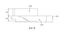
固定基座可具有一第一容置部以及一第二容置部,其中第一容置部容置反射元件,且第二容置部容置可動載體。其中,第一容置部在平行於光軸的方向上的高度為H1,第二容置部在平行於光軸的方向上的高度為H2,其可滿足下列條件:0.3 < H1/H2 < 3.3;藉此,可確保固定基座較穩固的空間配置範圍。其中,亦可滿足下列條件:0.5 ≤ H1/H2 ≤ 2.5;藉此,可進一步減少元件之間的歪斜,並且能提供高規格的光學成像品質。請參照圖6,係繪示有依照本發明第一實施例中參數H1和H2的示意圖。The fixed base can have a first accommodating portion and a second accommodating portion, wherein the first accommodating portion accommodates the reflective element, and the second accommodating portion accommodates the movable carrier. Wherein, the height of the first accommodating portion in the direction parallel to the optical axis is H1, and the height of the second accommodating portion in the direction parallel to the optical axis is H2, which can satisfy the following conditions: 0.3 < H1/H2 < 3.3; In this way, a relatively stable space configuration range of the fixed base can be ensured. Wherein, the following condition can also be satisfied: 0.5 ≤ H1/H2 ≤ 2.5; thereby, the skew between elements can be further reduced, and high-standard optical imaging quality can be provided. Please refer to FIG. 6 , which is a schematic diagram illustrating parameters H1 and H2 according to the first embodiment of the present invention.
成像鏡頭的最大視角(Field of view)為FOV,其可滿足下列條件:1度 ≤ FOV ≤ 45度。藉此,可提供具有攝遠功用的相機模組。此外,亦可適用於小視角的攝遠相機模組。The maximum viewing angle (Field of view) of the imaging lens is FOV, which can meet the following conditions: 1 degree ≤ FOV ≤ 45 degrees. Thereby, a camera module with a telephoto function can be provided. In addition, it can also be applied to a telephoto camera module with a small viewing angle.
成像鏡頭的焦距為EFL,其可滿足下列條件:10公釐 ≤ EFL ≤ 35公釐。藉此,可提供具有較高解像力的攝遠相機模組。此外,亦可適用於長焦距的攝遠相機模組。The focal length of the imaging lens is EFL, which can satisfy the following conditions: 10 mm ≤ EFL ≤ 35 mm. Thereby, a telephoto camera module with higher resolution can be provided. In addition, it can also be applied to a telephoto camera module with a long focal length.
電子感光元件的中心與成像鏡頭的光軸之間的距離為D,其可滿足下列條件:4公釐 < D < 18公釐;藉此,在有限的幾何空間下,可實現長焦成像系統的光學設計方案。其中,亦可滿足下列條件:5公釐 < D < 15公釐;藉此,可進一步降低產生雜散光的機率。請參照圖4,係繪示有依照本發明第一實施例中參數D的示意圖。The distance between the center of the electronic photosensitive element and the optical axis of the imaging lens is D, which can meet the following conditions: 4 mm < D < 18 mm; thereby, in a limited geometric space, a telephoto imaging system can be realized optical design scheme. Among them, the following conditions can also be met: 5 mm < D < 15 mm; thereby, the probability of stray light generation can be further reduced. Please refer to FIG. 4 , which is a schematic diagram illustrating the parameter D according to the first embodiment of the present invention.
本發明提供一種電子裝置,其包含前述的相機模組。藉此,配置本發明的相機模組有利於電子裝置薄型化。The present invention provides an electronic device, which includes the aforementioned camera module. Therefore, configuring the camera module of the present invention is beneficial to the thinning of the electronic device.
上述本發明相機模組中的各技術特徵皆可組合配置,而達到對應之功效。All the technical features in the above-mentioned camera module of the present invention can be configured in combination to achieve corresponding effects.
根據上述實施方式,以下提出具體實施例並配合圖式予以詳細說明。According to the above-mentioned implementation manners, specific embodiments are proposed below and described in detail with reference to the drawings.
<第一實施例><First embodiment>
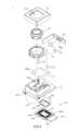
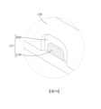
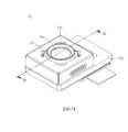
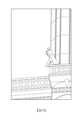
請參照圖1至圖7,其中圖1繪示依照本發明第一實施例之相機模組的立體示意圖,圖2繪示圖1之相機模組的分解示意圖,圖3繪示圖1之相機模組的另一側分解示意圖,圖4繪示圖1之相機模組沿4-4剖面線的剖面示意圖,圖5繪示圖1之相機模組的固定基座的上視示意圖,圖6繪示圖5之相機模組的固定基座沿6-6剖面線的剖面示意圖,且圖7繪示圖2中區域EL1的放大示意圖。Please refer to FIG. 1 to FIG. 7 , wherein FIG. 1 shows a schematic perspective view of a camera module according to a first embodiment of the present invention, FIG. 2 shows an exploded view of the camera module in FIG. 1 , and FIG. 3 shows a schematic view of the camera in FIG. 1 An exploded view of the other side of the module, Figure 4 shows a schematic cross-sectional view of the camera module in Figure 1 along the section line 4-4, Figure 5 shows a schematic top view of the fixed base of the camera module in Figure 1, Figure 6 A schematic cross-sectional view of the fixed base of the camera module in FIG. 5 along section line 6-6 is shown, and FIG. 7 shows an enlarged schematic view of the area EL1 in FIG. 2 .
相機模組1包含一外殼11、一固定基座12、一可動載體13、一成像鏡頭14、一電子感光元件15、四個引導元件16、一反射元件17、一自動對焦驅動裝置18以及一影像穩定驅動裝置19。The
外殼11裝設於固定基座12並共同形成一容置空間,且固定基座12具有一第一容置部121以及一第二容置部122。可動載體13位於所述容置空間中並容置於固定基座12的第二容置部122。成像鏡頭14固定於可動載體13上,且成像鏡頭14穿設於外殼11的開孔110。電子感光元件15設置於成像鏡頭14的成像面以接收成像鏡頭14的光學影像訊號。The
引導元件16設置於固定基座12與可動載體13之間,且引導元件16提供可動載體13相對固定基座12運動的一自由度。詳細來說,固定基座12更具有一引導結構120,可動載體13具有一引導結構130,且這些引導結構120、130互相對應並分別承靠於引導元件16。在本實施例中,四個引導元件16皆為球體;可動載體13的引導結構130為四個容置凹槽,分別容置四個引導元件16以固定四個引導元件16之間的相對位置;固定基座12的引導結構120為兩個滑槽,且所述兩個滑槽各自與其中兩個引導元件16承靠,並可界定可動載體13的移動範圍。透過引導元件16與固定基座12的引導結構120以及可動載體13的引導結構130互相配合,使得可動載體13可相對於固定基座12沿平行於成像鏡頭14的光軸IOA的方向DPA移動。The
反射元件17容置於固定基座12的第一容置部121,且固定基座12與反射元件17之間無相對運動,其中反射元件17的物側表面OBS對應於成像鏡頭14,且反射元件17的像側表面IMS對應於電子感光元件15。並且,成像鏡頭14、反射元件17與電子感光元件15係沿平行於成像鏡頭14的光軸IOA的方向DPA依序排列設置。在本實施例中,反射元件17具有四個反射面RLS,用於反射成像光線(如圖4所示),藉以可縮減幾何空間的光學設計,有助於提供相機模組1微型化,並且可避免產生鏡像的影像訊號。本實施例之反射元件17可為塑膠反射元件或玻璃反射元件。The
自動對焦驅動裝置18用以提供成像鏡頭14自動對焦的驅動力。詳細來說,自動對焦驅動裝置18包含一第一磁石元件181以及一第一線圈元件182,其中第一磁石元件181設置於可動載體13,且第一線圈元件182設置於外殼11的一固定板111並對應於第一磁石元件181。由於外殼11係固定裝設於固定基座12,從而設置於外殼11之固定板111上的第一線圈元件182係透過外殼11固定設置在固定基座12,亦即第一線圈元件182與固定基座12之間不可相對移動。設置於可動載體13的第一磁石元件181可透過與第一線圈元件182之間的交互作用產生的一驅動磁力(指利用電磁交互作用所產生的勞倫茲力)而帶動可動載體13一起相對於固定基座12移動,且透過引導元件16與固定基座12的引導結構120以及可動載體13的引導結構130互相配合,使得可動載體13以及設置於可動載體13的成像鏡頭14可相對於固定基座12沿平行於成像鏡頭14的光軸IOA的方向DPA移動(如圖4所示),以達到自動對焦的功效。The
影像穩定驅動裝置19用以提供電子感光元件15影像穩定的驅動力。詳細來說,影像穩定驅動裝置19包含四個第二磁石元件191、一軟性電路板192、多個彈性支撐元件193以及四個第二線圈元件194。第二磁石元件191固定於固定基座12的四個磁石容置部123,且磁石容置部123例如為具有對應第二磁石元件191的形狀的容置槽。軟性電路板192設置於固定基座12。軟性電路板192包含一內基板ISP以及環繞內基板ISP的一外環板OCP,其中外環板OCP附接於固定基座12,且內基板ISP透過彈性支撐元件193可活動地實體連接於外環板OCP並同時電性連接外環板OCP。第二線圈元件194以及電子感光元件15設置於內基板ISP上並透過彈性支撐元件193而可相對於外環板OCP移動,第二磁石元件191分別對應於電子感光元件15的四個邊上,且第二線圈元件194和第二磁石元件191彼此對應設置。如此,第二線圈元件194可透過與第二磁石元件191之間的交互作用產生的一驅動磁力而帶動內基板ISP和電子感光元件15一起相對於固定基座12移動。在本實施例中,電子感光元件15可相對於固定基座12沿垂直於成像鏡頭14的光軸IOA的方向DPE移動(如圖4所示),以達到影像穩定的功效。The image stabilizing driving
在本實施例中,影像穩定驅動裝置19的第二線圈元件194以及自動對焦驅動裝置18的第一磁石元件181皆可相對於固定基座12移動,透過此種驅動配置方式可降低控制訊號的干擾。In this embodiment, both the
在本實施例中,成像鏡頭14、反射元件17與電子感光元件15沿平行於成像鏡頭14的光軸IOA的方向DPA依序排列設置,其為組裝時較為容易的配置順序,藉以可提高自動化效率。In this embodiment, the
在本實施例中,固定基座12由射出成型製成且具有四個注料痕GT,其中四個注料痕GT分別設置於固定基座12的四個側邊的角落鄰近處,從而可提供較佳的成型效率。在本實施例中,固定基座12可包含黑色塑膠材料。如圖7所示,每個注料痕GT各包含一降面部RSP以及一切痕部CTP,但本發明不以此為限。In this embodiment, the fixed
固定基座12的第一容置部121在平行於光軸IOA的方向DPA上的高度為H1,固定基座12的第二容置部122在平行於光軸IOA的方向DPA上的高度為H2,其滿足下列條件:H1 = 2.78公釐;H2 = 3.8公釐;以及H1/H2 = 0.73。The height of the first
成像鏡頭14的最大視角為FOV,其滿足下列條件:FOV = 20.3度。The maximum viewing angle of the
成像鏡頭14的焦距為EFL,其滿足下列條件:EFL = 17.0公釐。The focal length of the
電子感光元件15的中心與成像鏡頭14的光軸IOA之間的距離為D,其滿足下列條件:D = 8.066公釐。The distance between the center of the electronic
<第二實施例><Second embodiment>
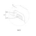
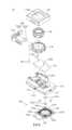
請參照圖8至圖14,其中圖8繪示依照本發明第二實施例之相機模組的立體示意圖,圖9繪示圖8之相機模組的分解示意圖,圖10繪示圖8之相機模組的另一側分解示意圖,圖11繪示圖8之相機模組沿11-11剖面線的剖面示意圖,圖12繪示圖8之相機模組的固定基座的上視示意圖,圖13繪示圖12之相機模組的固定基座沿13-13剖面線的剖面示意圖,且圖14繪示圖9中區域EL2的放大示意圖。Please refer to FIG. 8 to FIG. 14 , wherein FIG. 8 shows a perspective view of a camera module according to a second embodiment of the present invention, FIG. 9 shows an exploded view of the camera module in FIG. 8 , and FIG. 10 shows a schematic view of the camera in FIG. 8 The other side of the exploded schematic diagram of the module, Figure 11 is a schematic cross-sectional view of the camera module in Figure 8 along the section line 11-11, Figure 12 is a schematic top view of the fixed base of the camera module in Figure 8, Figure 13 12 is a schematic cross-sectional view of the fixed base of the camera module along the section line 13 - 13 , and FIG. 14 is an enlarged schematic view of the area EL2 in FIG. 9 .
相機模組1b包含一外殼11b、一固定基座12b、一可動載體13b、一成像鏡頭14b、一電子感光元件15b、四個引導元件16b、一反射元件17b、一自動對焦驅動裝置18b以及一影像穩定驅動裝置19b。The camera module 1b includes a
外殼11b裝設於固定基座12b並共同形成一容置空間,且固定基座12b具有一第一容置部121b以及一第二容置部122b。可動載體13b位於所述容置空間中並容置於固定基座12b的第二容置部122b。成像鏡頭14b固定於可動載體13b上,且成像鏡頭14b穿設於外殼11b的開孔110b。電子感光元件15b設置於成像鏡頭14b的成像面以接收成像鏡頭14b的光學影像訊號。The
引導元件16b設置於固定基座12b與可動載體13b之間,且引導元件16b提供可動載體13b相對固定基座12b運動的一自由度。詳細來說,固定基座12b更具有一引導結構120b,可動載體13b具有一引導結構130b,且這些引導結構120b、130b互相對應並分別承靠於引導元件16b。在本實施例中,四個引導元件16b皆為球體;可動載體13b的引導結構130b為四個容置凹槽,分別容置四個引導元件16b以固定四個引導元件16b之間的相對位置;固定基座12b的引導結構120b為兩個滑槽,且所述兩個滑槽各自與其中兩個引導元件16b承靠,並可界定可動載體13b的移動範圍。透過引導元件16b與固定基座12b的引導結構120b以及可動載體13b的引導結構130b互相配合,使得可動載體13b可相對於固定基座12b沿平行於成像鏡頭14b的光軸IOA的方向DPA移動。The
反射元件17b容置於固定基座12b的第一容置部121b,且固定基座12b與反射元件17b之間無相對運動,其中反射元件17b的物側表面OBS對應於成像鏡頭14b,且反射元件17b的像側表面IMS對應於電子感光元件15b。並且,成像鏡頭14b、反射元件17b與電子感光元件15b係沿平行於成像鏡頭14b的光軸IOA的方向DPA依序排列設置。在本實施例中,反射元件17b具有四個反射面RLS,用於反射成像光線(如圖11所示),藉以可縮減幾何空間的光學設計,有助於提供相機模組1b微型化,並且可避免產生鏡像的影像訊號。本實施例之反射元件17b可為塑膠反射元件或玻璃反射元件。The
自動對焦驅動裝置18b用以提供成像鏡頭14b自動對焦的驅動力。詳細來說,自動對焦驅動裝置18b包含一第一磁石元件181b以及一第一線圈元件182b,其中第一磁石元件181b設置於可動載體13b,且第一線圈元件182b設置於外殼11b的一固定板111b並對應於第一磁石元件181b。由於外殼11b係固定裝設於固定基座12b,從而設置於外殼11b之固定板111b上的第一線圈元件182b係透過外殼11b固定設置在固定基座12b,亦即第一線圈元件182b與固定基座12b之間不可相對移動。設置於可動載體13b的第一磁石元件181b可透過與第一線圈元件182b之間的交互作用產生的一驅動磁力(勞倫茲力)而帶動可動載體13b一起相對於固定基座12b移動,且透過引導元件16b與固定基座12b的引導結構120b以及可動載體13b的引導結構130b互相配合,使得可動載體13b以及設置於可動載體13b的成像鏡頭14b可相對於固定基座12b沿平行於成像鏡頭14b的光軸IOA的方向DPA移動(如圖11所示),以達到自動對焦的功效。The auto-
影像穩定驅動裝置19b用以提供電子感光元件15b影像穩定的驅動力。詳細來說,影像穩定驅動裝置19b包含四個第二磁石元件191b、一軟性電路板192b、多個彈性支撐元件193b以及四個第二線圈元件194b。第二磁石元件191b固定於固定基座12b的四個磁石容置部123b,且磁石容置部123b例如為具有對應第二磁石元件191b的形狀的容置槽。軟性電路板192b設置於固定基座12b。軟性電路板192b包含一內基板ISP以及環繞內基板ISP的一外環板OCP,其中外環板OCP附接於固定基座12b,且內基板ISP透過彈性支撐元件193b可活動地實體連接於外環板OCP並同時電性連接外環板OCP。第二線圈元件194b以及電子感光元件15b設置於內基板ISP上並透過彈性支撐元件193b而可相對於外環板OCP移動,第二磁石元件191b分別對應於電子感光元件15b的四個角落處,且第二線圈元件194b和第二磁石元件191b彼此對應設置。如此,第二線圈元件194b可透過與第二磁石元件191b之間的交互作用產生的一驅動磁力而帶動內基板ISP和電子感光元件15b一起相對於固定基座12b移動。在本實施例中,電子感光元件15b可相對於固定基座12b沿垂直於成像鏡頭14b的光軸IOA的方向DPE移動(如圖11所示),以達到影像穩定的功效。The image stabilizing
在本實施例中,影像穩定驅動裝置19b的第二線圈元件194b以及自動對焦驅動裝置18b的第一磁石元件181b皆可相對於固定基座12b移動,透過此種驅動配置方式可降低控制訊號的干擾。In this embodiment, both the
在本實施例中,成像鏡頭14b、反射元件17b與電子感光元件15b沿平行於成像鏡頭14b的光軸IOA的方向DPA依序排列設置,其為組裝時較為容易的配置順序,藉以可提高自動化效率。In this embodiment, the
在本實施例中,固定基座12b由射出成型製成且具有四個注料痕GT,其中四個注料痕GT分別設置於固定基座12b的四個側邊的中央處,從而可提供較佳的成型效率。在本實施例中,固定基座12b可包含黑色塑膠材料。如圖14所示,每個注料痕GT各包含一降面部RSP以及一切痕部CTP,但本發明不以此為限。In this embodiment, the fixed
固定基座12b的第一容置部121b在平行於光軸IOA的方向DPA上的高度為H1,固定基座12b的第二容置部122b在平行於光軸IOA的方向DPA上的高度為H2,其滿足下列條件:H1 = 2.78公釐;H2 = 3.8公釐;以及H1/H2 = 0.73。The height of the first
成像鏡頭14b的最大視角為FOV,其滿足下列條件:FOV = 10.1度。The maximum viewing angle of the
成像鏡頭14b的焦距為EFL,其滿足下列條件:EFL = 28.2公釐。The focal length of the
電子感光元件15b的中心與成像鏡頭14b的光軸IOA之間的距離為D,其滿足下列條件:D = 8.066公釐。The distance between the center of the electronic
<第三實施例><Third embodiment>
請參照圖15至圖21,其中圖15繪示依照本發明第三實施例之相機模組的立體示意圖,圖16繪示圖15之相機模組的分解示意圖,圖17繪示圖15之相機模組的另一側分解示意圖,圖18繪示圖15之相機模組沿18-18剖面線的剖面示意圖,圖19繪示圖15之相機模組的固定基座的上視示意圖,圖20繪示圖19之相機模組的固定基座沿20-20剖面線的剖面示意圖,且圖21繪示圖16中區域EL3的放大示意圖。Please refer to FIG. 15 to FIG. 21 , wherein FIG. 15 shows a perspective view of a camera module according to a third embodiment of the present invention, FIG. 16 shows an exploded view of the camera module in FIG. 15 , and FIG. 17 shows the camera in FIG. 15 The other side of the exploded schematic diagram of the module, Figure 18 is a schematic cross-sectional view of the camera module in Figure 15 along the section line 18-18, Figure 19 is a schematic top view of the fixed base of the camera module in Figure 15, Figure 20 19 shows a schematic cross-sectional view of the fixed base of the camera module along the section line 20-20, and FIG. 21 shows an enlarged schematic view of the area EL3 in FIG. 16 .
相機模組1c包含一外殼11c、一固定基座12c、一可動載體13c、一成像鏡頭14c、一電子感光元件15c、四個引導元件16c、一反射元件17c、一自動對焦驅動裝置18c以及一影像穩定驅動裝置19c。The
外殼11c裝設於固定基座12c並共同形成一容置空間,且固定基座12c具有一第一容置部121c以及一第二容置部122c。可動載體13c位於所述容置空間中並容置於固定基座12c的第二容置部122c。電子感光元件15c設置於成像鏡頭14c的成像面以接收成像鏡頭14c的光學影像訊號。在本實施例中,可動載體13c為透鏡載體,且成像鏡頭14c為成像透鏡組,其直接裝設於可動載體13c內。如圖18所示,可動載體13c和成像鏡頭14c穿設於外殼11c的開孔110c。The
引導元件16c設置於固定基座12c與可動載體13c之間,且引導元件16c提供可動載體13c相對固定基座12c運動的一自由度。詳細來說,固定基座12c更具有一引導結構120c,可動載體13c具有一引導結構130c,且這些引導結構120c、130c互相對應並分別承靠於引導元件16c。在本實施例中,四個引導元件16c皆為球體;可動載體13c的引導結構130c為四個容置凹槽,分別容置四個引導元件16c以固定四個引導元件16c之間的相對位置;固定基座12c的引導結構120c為兩個滑槽,且所述兩個滑槽各自與其中兩個引導元件16c承靠,並可界定可動載體13c的移動範圍。透過引導元件16c與固定基座12c的引導結構120c以及可動載體13c的引導結構130c互相配合,使得可動載體13c可相對於固定基座12c沿平行於成像鏡頭14c的光軸IOA的方向DPA移動。The
反射元件17c容置於固定基座12c的第一容置部121c,且固定基座12c與反射元件17c之間無相對運動,其中反射元件17c的物側表面OBS對應於成像鏡頭14c,且反射元件17c的像側表面IMS對應於電子感光元件15c。並且,成像鏡頭14c、反射元件17c與電子感光元件15c係沿平行於成像鏡頭14c的光軸IOA的方向DPA依序排列設置。在本實施例中,反射元件17c具有四個反射面RLS,用於反射成像光線(如圖18所示),藉以可縮減幾何空間的光學設計,有助於提供相機模組1c微型化,並且可避免產生鏡像的影像訊號。本實施例之反射元件17c可為塑膠反射元件或玻璃反射元件。The
自動對焦驅動裝置18c用以提供成像鏡頭14c自動對焦的驅動力。詳細來說,自動對焦驅動裝置18c包含一第一磁石元件181c以及一第一線圈元件182c,其中第一磁石元件181c設置於可動載體13c,且第一線圈元件182c設置於外殼11c的一固定板111c並對應於第一磁石元件181c。由於外殼11c係固定裝設於固定基座12c,從而設置於外殼11c之固定板111c上的第一線圈元件182c係透過外殼11c固定設置在固定基座12c,亦即第一線圈元件182c與固定基座12c之間不可相對移動。設置於可動載體13c的第一磁石元件181c可透過與第一線圈元件182c之間的交互作用產生的一驅動磁力(勞倫茲力)而帶動可動載體13c一起相對於固定基座12c移動,且透過引導元件16c與固定基座12c的引導結構120c以及可動載體13c的引導結構130c互相配合,使得可動載體13c以及設置於可動載體13c的成像鏡頭14c可相對於固定基座12c沿平行於成像鏡頭14c的光軸IOA的方向DPA移動(如圖18所示),以達到自動對焦的功效。The
影像穩定驅動裝置19c用以提供電子感光元件15c影像穩定的驅動力。詳細來說,影像穩定驅動裝置19c包含四個第二磁石元件191c、一軟性電路板192c、多個彈性支撐元件193c以及四個第二線圈元件194c。第二磁石元件191c固定於固定基座12c的四個磁石容置部123c,且磁石容置部123c例如為具有對應第二磁石元件191c的形狀的容置槽。軟性電路板192c設置於固定基座12c。軟性電路板192c包含一內基板ISP以及環繞內基板ISP的一外環板OCP,其中外環板OCP附接於固定基座12c,且內基板ISP透過彈性支撐元件193c可活動地實體連接於外環板OCP並同時電性連接外環板OCP。第二線圈元件194c以及電子感光元件15c設置於內基板ISP上並透過彈性支撐元件193c而可相對於外環板OCP移動,第二磁石元件191c分別對應於電子感光元件15c的四個角落處,且第二線圈元件194c和第二磁石元件191c彼此對應設置。如此,第二線圈元件194c可透過與第二磁石元件191c之間的交互作用產生的一驅動磁力而帶動內基板ISP和電子感光元件15c一起相對於固定基座12c移動。在本實施例中,電子感光元件15c可相對於固定基座12c沿垂直於成像鏡頭14c的光軸IOA的方向DPE移動(如圖18所示),以達到影像穩定的功效。The image stabilizing
在本實施例中,影像穩定驅動裝置19c的第二線圈元件194c以及自動對焦驅動裝置18c的第一磁石元件181c皆可相對於固定基座12c移動,透過此種驅動配置方式可降低控制訊號的干擾。In this embodiment, both the
在本實施例中,成像鏡頭14c、反射元件17c與電子感光元件15c沿平行於成像鏡頭14c的光軸IOA的方向DPA依序排列設置,其為組裝時較為容易的配置順序,藉以可提高自動化效率。In this embodiment, the
在本實施例中,固定基座12c由射出成型製成且具有四個注料痕GT,其中四個注料痕GT分別設置於固定基座12c的其中兩個側邊的角落鄰近處,從而可提供較佳的成型效率。在本實施例中,固定基座12c可包含黑色塑膠材料。如圖21所示,每個注料痕GT各包含一降面部RSP以及一切痕部CTP,但本發明不以此為限。In this embodiment, the fixed
固定基座12c的第一容置部121c在平行於光軸IOA的方向DPA上的高度為H1,固定基座12c的第二容置部122c在平行於光軸IOA的方向DPA上的高度為H2,其滿足下列條件:H1 = 2.78公釐;H2 = 3.8公釐;以及H1/H2 = 0.73。The height of the first
成像鏡頭14c的最大視角為FOV,其滿足下列條件:FOV = 20.3度。The maximum viewing angle of the
成像鏡頭14c的焦距為EFL,其滿足下列條件:EFL = 17.0公釐。The focal length of the
電子感光元件15c的中心與成像鏡頭14c的光軸IOA之間的距離為D,其滿足下列條件:D = 8.066公釐。The distance between the center of the electronic
<第四實施例><Fourth embodiment>
請參照圖22,為繪示依照本發明第四實施例之相機模組的剖面示意圖。Please refer to FIG. 22 , which is a schematic cross-sectional view of a camera module according to a fourth embodiment of the present invention.
本實施例之相機模組1d的結構和第三實施例之相機模組1c的結構相似,其主要差異在於本實施例之相機模組1d的反射元件17d係具有兩個反射面RLS,且固定基座12d用以容置反射元件17d的第一容置部121d在平行於光軸IOA的方向DPA上具有不同的高度。此外,本實施例之相機模組1d還具有以下不同於第三實施例之相機模組1c的特徵。The structure of the
固定基座12d的第一容置部121d在平行於光軸IOA的方向DPA上的高度為H1,固定基座12d的第二容置部122d在平行於光軸IOA的方向DPA上的高度為H2,其滿足下列條件:H1 = 4.9公釐;H2 = 3.8公釐;以及H1/H2 = 1.29。The height of the first
成像鏡頭14d的最大視角為FOV,其滿足下列條件:FOV = 19.5度。The maximum viewing angle of the
成像鏡頭14d的焦距為EFL,其滿足下列條件:EFL = 14.4公釐。The focal length of the
電子感光元件15d的中心與成像鏡頭14d的光軸IOA之間的距離為D,其滿足下列條件:D = 5.995公釐。The distance between the center of the electronic
本發明所揭露的相機模組不以上述實施例中反射元件的數量為限,在其他實施例中,攝影模組可包含兩個以上的反射元件。The camera module disclosed in the present invention is not limited by the number of reflective elements in the above embodiments. In other embodiments, the camera module may include more than two reflective elements.
<第五實施例><Fifth Embodiment>
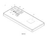
請參照圖23與圖24,其中圖23繪示依照本發明第五實施例的一種電子裝置之一側的立體示意圖,且圖24繪示圖23之電子裝置之另一側的立體示意圖。Please refer to FIG. 23 and FIG. 24 , wherein FIG. 23 shows a perspective view of one side of an electronic device according to a fifth embodiment of the present invention, and FIG. 24 shows a perspective view of the other side of the electronic device of FIG. 23 .
在本實施例中,電子裝置5為一智慧型手機。電子裝置5包含多個取像裝置、閃光燈模組51、對焦輔助模組52、影像訊號處理器53(Image Signal Processor)、顯示模組(使用者介面)54以及影像軟體處理器(未繪示)。In this embodiment, the
這些取像裝置包含超廣角取像裝置50a、高畫素取像裝置50b、攝遠取像裝置50c以及攝遠取像裝置50d。其中,攝遠取像裝置50d為本發明第一實施例的相機模組1,但本發明不以此為限,攝遠取像裝置50d亦可例如為上述本發明其他實施例的相機模組。此外,除了攝遠取像裝置50d之外,電子裝置5的其他取像裝置50a、50b、50c中亦可有至少一者為上述本發明實施例的相機模組。These imaging devices include a super wide-
超廣角取像裝置50a具有容納多景色的功能。圖25繪示以超廣角取像裝置50a擷取影像的示意圖。The super wide-
高畫素取像裝置50b具有高解析且低變形的功能。高畫素取像裝置50b能進一步擷取圖25之影像中的部分區域。圖26繪示以高畫素取像裝置50b擷取影像的示意圖。The high-
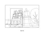
攝遠取像裝置50c及攝遠取像裝置50d具有高倍數的放大功能。攝遠取像裝置50c或攝遠取像裝置50d能進一步擷取圖26之影像中的部分區域。圖27繪示以攝遠取像裝置50c或攝遠取像裝置50d擷取影像的示意圖。其中,取像裝置的最大視角(FOV)對應於圖27的視角。The
當使用者拍攝被攝物時,電子裝置5利用超廣角取像裝置50a、高畫素取像裝置50b、攝遠取像裝置50c或是攝遠取像裝置50d聚光取像,啟動閃光燈模組51進行補光,並使用對焦輔助模組52提供的被攝物之物距資訊進行快速對焦,再加上影像訊號處理器53進行影像最佳化處理,來進一步提升取像裝置所產生的影像品質,同時提供變焦功能。對焦輔助模組52可採用紅外線或雷射對焦輔助系統來達到快速對焦。顯示模組54可採用觸控螢幕,具備觸控功能,可透過手動的方式調整拍攝視角,因此切換不同的取像裝置,並配合影像軟體處理器的多樣化功能進行影像拍攝以及影像處理(或可利用實體拍攝按鈕進行拍攝)。經由影像軟體處理器處理後的影像可顯示於顯示模組54。When the user takes a picture of a subject, the
<第六實施例><Sixth embodiment>
請參照圖28,係繪示依照本發明第六實施例的一種電子裝置之一側的立體示意圖。Please refer to FIG. 28 , which is a schematic perspective view of one side of an electronic device according to a sixth embodiment of the present invention.
在本實施例中,電子裝置6為一智慧型手機。電子裝置6包含取像裝置60z、取像裝置60a、取像裝置60b、取像裝置60c、取像裝置60d、取像裝置60e、取像裝置60f、取像裝置60g、取像裝置60h、閃光燈模組61、影像訊號處理器、顯示裝置以及影像軟體處理器(未繪示)。取像裝置60z、取像裝置60a、取像裝置60b、取像裝置60c、取像裝置60d、取像裝置60e、取像裝置60f、取像裝置60g與取像裝置60h係皆配置於電子裝置6的同一側,而顯示裝置則配置於電子裝置6的另一側。其中,取像裝置60b為本發明第一實施例的相機模組1,但本發明不以此為限,取像裝置60b亦可例如為上述本發明其他實施例的相機模組。此外,除了取像裝置60b之外,電子裝置6的其他取像裝置60z、60a、60c、60d、60e、60f、60g、60h中亦可有至少一者為上述本發明實施例的相機模組。In this embodiment, the
取像裝置60z為一攝遠取像裝置,取像裝置60a為一攝遠取像裝置,取像裝置60b為一攝遠取像裝置,取像裝置60c為一攝遠取像裝置,取像裝置60d為一廣角取像裝置,取像裝置60e為一廣角取像裝置,取像裝置60f為一超廣角取像裝置,取像裝置60g為一超廣角取像裝置,且取像裝置60h為一飛時測距(Time of flight,ToF)取像裝置。本實施例之取像裝置60z、取像裝置60a、取像裝置60b、取像裝置60c、取像裝置60d、取像裝置60e、取像裝置60f與取像裝置60g具有相異的視角,使電子裝置6可提供不同的放大倍率,以達到光學變焦的拍攝效果。此外,取像裝置60z與取像裝置60a為具有光轉折元件配置的攝遠取像裝置。另外,取像裝置60h係可取得影像的深度資訊。上述電子裝置6以包含多個取像裝置60z、60a、60b、60c、60d、60e、60f、60g、60h為例,但取像裝置的數量與配置並非用以限制本發明。當使用者拍攝被攝物時,電子裝置6利用取像裝置60z、取像裝置60a、取像裝置60b、取像裝置60c、取像裝置60d、取像裝置60e、取像裝置60f、取像裝置60g或取像裝置60h聚光取像,啟動閃光燈模組61進行補光,並且以類似於前述實施例的方式進行後續處理,在此不再加以贅述。The
本發明的相機模組不以應用於智慧型手機為限。相機模組更可視需求應用於移動對焦的系統,並兼具優良像差修正與良好成像品質的特色。舉例來說,相機模組可多方面應用於三維(3D)影像擷取、數位相機、行動裝置、數位平板、智慧型電視、網路監控設備、行車記錄器、倒車顯影裝置、多鏡頭裝置、辨識系統、體感遊戲機與穿戴式裝置等電子裝置中。前揭電子裝置僅是示範性地說明本發明的實際運用例子,並非限制本發明之相機模組的運用範圍。The camera module of the present invention is not limited to be applied to smart phones. The camera module can be applied to the mobile focus system according to the needs, and has the characteristics of excellent aberration correction and good imaging quality. For example, the camera module can be widely used in three-dimensional (3D) image capture, digital cameras, mobile devices, digital tablets, smart TVs, network monitoring equipment, driving recorders, reverse development devices, multi-lens devices, In electronic devices such as identification systems, somatosensory game consoles and wearable devices. The electronic device disclosed above is only an example to illustrate the practical application of the present invention, and does not limit the scope of application of the camera module of the present invention.
雖然本發明以前述之實施例揭露如上,然而這些實施例並非用以限定本發明。在不脫離本發明之精神和範圍內,所為之更動與潤飾,均屬本發明之專利保護範圍。關於本發明所界定之保護範圍請參考所附之申請專利範圍。Although the present invention is disclosed above with the aforementioned embodiments, these embodiments are not intended to limit the present invention. Without departing from the spirit and scope of the present invention, all changes and modifications are within the scope of patent protection of the present invention. For the scope of protection defined by the present invention, please refer to the appended scope of patent application.
1,1b,1c,1d:相機模組 11,11b,11c:外殼 110,110b,110c:開孔 111,111b,111c:固定板 12,12b,12c,12d:固定基座 120,120b,120c:引導結構 121,121b,121c,121d:第一容置部 122,122b,122c,122d:第二容置部 123,123b,123c:磁石容置部 GT:注料痕 RSP:降面部 CTP:切痕部 13,13b,13c:可動載體 130,130b,130c:引導結構 14,14b,14c,14d:成像鏡頭 15,15b,15c,15d:電子感光元件 16,16b,16c:引導元件 17,17b,17c,17d:反射元件 OBS:物側表面 IMS:像側表面 RLS:反射面 18,18b,18c:自動對焦驅動裝置 181,181b,181c:第一磁石元件 182,182b,182c:第一線圈元件 19,19b,19c:影像穩定驅動裝置 191,191b,191c:第二磁石元件 192,192b,192c:軟性電路板 ISP:內基板 OCP:外環板 193,193b,193c:彈性支撐元件 194,194b,194c:第二線圈元件 5,6:電子裝置 50a:超廣角取像裝置 50b:高畫素取像裝置 50c,50d:攝遠取像裝置 51:閃光燈模組 52:對焦輔助模組 53:影像訊號處理器 54:顯示模組 60z,60a,60b,60c,60d,60e,60f,60g,60h:取像裝置 61:閃光燈模組 IOA:光軸 DPA:平行於光軸的方向 DPE:垂直於光軸的方向 H1:第一容置部在平行於光軸的方向上的高度 H2:第二容置部在平行於光軸的方向上的高度 D:電子感光元件的中心與成像鏡頭的光軸之間的距離 FOV:成像鏡頭的最大視角 EFL:成像鏡頭的焦距1,1b,1c,1d: camera module 11, 11b, 11c: shell 110, 110b, 110c: opening 111, 111b, 111c: fixed plate 12, 12b, 12c, 12d: fixed base 120, 120b, 120c: bootstrap structure 121, 121b, 121c, 121d: first accommodating part 122, 122b, 122c, 122d: second accommodation part 123, 123b, 123c: magnet accommodating part GT: injection marks RSP: descending face CTP: notch part 13,13b,13c: movable carrier 130, 130b, 130c: bootstrap structure 14, 14b, 14c, 14d: imaging lens 15, 15b, 15c, 15d: electronic photosensitive element 16, 16b, 16c: guide elements 17, 17b, 17c, 17d: reflective elements OBS: object side surface IMS: image side surface RLS: reflective surface 18, 18b, 18c: Auto-focus driving device 181, 181b, 181c: first magnet element 182, 182b, 182c: first coil element 19, 19b, 19c: image stabilization driver 191, 191b, 191c: second magnet element 192, 192b, 192c: flexible circuit board ISP: inner substrate OCP: outer ring plate 193, 193b, 193c: elastic support elements 194, 194b, 194c: second coil element 5,6: Electronic device 50a: Super wide-angle imaging device 50b: High-resolution imaging device 50c, 50d: telephoto imaging device 51:Flash module 52:Focus assist module 53: Image signal processor 54:Display module 60z, 60a, 60b, 60c, 60d, 60e, 60f, 60g, 60h: imaging device 61:Flash module IOA: optical axis DPA: direction parallel to the optical axis DPE: the direction perpendicular to the optical axis H1: the height of the first accommodation part in the direction parallel to the optical axis H2: the height of the second accommodation part in the direction parallel to the optical axis D: The distance between the center of the electronic photosensitive element and the optical axis of the imaging lens FOV: the maximum viewing angle of the imaging lens EFL: focal length of imaging lens
圖1繪示依照本發明第一實施例之相機模組的立體示意圖。 圖2繪示圖1之相機模組的分解示意圖。 圖3繪示圖1之相機模組的另一側分解示意圖。 圖4繪示圖1之相機模組沿4-4剖面線的剖面示意圖。 圖5繪示圖1之相機模組的固定基座的上視示意圖。 圖6繪示圖5之相機模組的固定基座沿6-6剖面線的剖面示意圖。 圖7繪示圖2中區域EL1的放大示意圖。 圖8繪示依照本發明第二實施例之相機模組的立體示意圖。 圖9繪示圖8之相機模組的分解示意圖。 圖10繪示圖8之相機模組的另一側分解示意圖。 圖11繪示圖8之相機模組沿11-11剖面線的剖面示意圖。 圖12繪示圖8之相機模組的固定基座的上視示意圖。 圖13繪示圖12之相機模組的固定基座沿13-13剖面線的剖面示意圖。 圖14繪示圖9中區域EL2的放大示意圖。 圖15繪示依照本發明第三實施例之相機模組的立體示意圖。 圖16繪示圖15之相機模組的分解示意圖。 圖17繪示圖15之相機模組的另一側分解示意圖。 圖18繪示圖15之相機模組沿18-18剖面線的剖面示意圖。 圖19繪示圖15之相機模組的固定基座的上視示意圖。 圖20繪示圖19之相機模組的固定基座沿20-20剖面線的剖面示意圖。 圖21繪示圖16中區域EL3的放大示意圖。 圖22繪示依照本發明第四實施例之相機模組的剖面示意圖。 圖23繪示依照本發明第五實施例的一種電子裝置之一側的立體示意圖。 圖24繪示圖23之電子裝置之另一側的立體示意圖。 圖25繪示以超廣角相機模組擷取影像的示意圖。 圖26繪示以高畫素相機模組擷取影像的示意圖。 圖27繪示以攝遠相機模組擷取影像的示意圖。 圖28繪示依照本發明第六實施例的一種電子裝置之一側的立體示意圖。FIG. 1 is a schematic perspective view of a camera module according to a first embodiment of the present invention. FIG. 2 is an exploded schematic diagram of the camera module in FIG. 1 . FIG. 3 is an exploded schematic diagram of another side of the camera module in FIG. 1 . FIG. 4 is a schematic cross-sectional view of the camera module in FIG. 1 along section line 4-4. FIG. 5 is a schematic top view of a fixed base of the camera module shown in FIG. 1 . FIG. 6 is a schematic cross-sectional view of the fixed base of the camera module in FIG. 5 along section line 6-6. FIG. 7 is an enlarged schematic diagram of the area EL1 in FIG. 2 . FIG. 8 is a schematic perspective view of a camera module according to a second embodiment of the present invention. FIG. 9 is an exploded schematic view of the camera module in FIG. 8 . FIG. 10 is an exploded schematic diagram of another side of the camera module in FIG. 8 . FIG. 11 is a schematic cross-sectional view of the camera module in FIG. 8 along section line 11-11. FIG. 12 is a schematic top view of the fixed base of the camera module in FIG. 8 . FIG. 13 is a schematic cross-sectional view of the fixed base of the camera module in FIG. 12 along the section line 13 - 13 . FIG. 14 is an enlarged schematic view of the area EL2 in FIG. 9 . FIG. 15 is a schematic perspective view of a camera module according to a third embodiment of the present invention. FIG. 16 is an exploded schematic diagram of the camera module in FIG. 15 . FIG. 17 is an exploded schematic diagram of another side of the camera module in FIG. 15 . FIG. 18 is a schematic cross-sectional view of the camera module in FIG. 15 along the section line 18-18. FIG. 19 is a schematic top view of the fixed base of the camera module in FIG. 15 . FIG. 20 is a schematic cross-sectional view of the fixed base of the camera module in FIG. 19 along the section line 20-20. FIG. 21 is an enlarged schematic diagram of the area EL3 in FIG. 16 . FIG. 22 is a schematic cross-sectional view of a camera module according to a fourth embodiment of the present invention. FIG. 23 is a schematic perspective view of one side of an electronic device according to a fifth embodiment of the present invention. FIG. 24 is a schematic perspective view of another side of the electronic device shown in FIG. 23 . FIG. 25 shows a schematic diagram of capturing images with a super wide-angle camera module. FIG. 26 shows a schematic diagram of capturing images with a high-resolution camera module. FIG. 27 shows a schematic diagram of capturing images with a telephoto camera module. FIG. 28 is a schematic perspective view of one side of an electronic device according to a sixth embodiment of the present invention.
12:固定基座12: Fixed base
13:可動載體13: Movable carrier
14:成像鏡頭14: Imaging lens
15:電子感光元件15: Electronic photosensitive element
OBS:物側表面OBS: object side surface
IMS:像側表面IMS: image side surface
RLS:反射面RLS: reflective surface
IOA:光軸IOA: optical axis
DPA:平行於光軸的方向DPA: direction parallel to the optical axis
DPE:垂直於光軸的方向DPE: the direction perpendicular to the optical axis
D:電子感光元件的中心與成像鏡頭的光軸之間的距離D: The distance between the center of the electronic photosensitive element and the optical axis of the imaging lens
Claims (24)
Translated fromChineseApplications Claiming Priority (2)
| Application Number | Priority Date | Filing Date | Title |
|---|---|---|---|
| US202263298938P | 2022-01-12 | 2022-01-12 | |
| US63/298,938 | 2022-01-12 |
Publications (2)
| Publication Number | Publication Date |
|---|---|
| TW202328792Atrue TW202328792A (en) | 2023-07-16 |
| TWI815299B TWI815299B (en) | 2023-09-11 |
Family
ID=83146198
Family Applications (1)
| Application Number | Title | Priority Date | Filing Date |
|---|---|---|---|
| TW111104445ATWI815299B (en) | 2022-01-12 | 2022-02-08 | Camera module and electronic device |
Country Status (4)
| Country | Link |
|---|---|
| US (3) | US20230224562A1 (en) |
| EP (1) | EP4212936A1 (en) |
| CN (2) | CN217406638U (en) |
| TW (1) | TWI815299B (en) |
Families Citing this family (2)
| Publication number | Priority date | Publication date | Assignee | Title |
|---|---|---|---|---|
| US20220091398A1 (en)* | 2020-09-24 | 2022-03-24 | Apple Inc. | Telephoto Camera with a Stationary Optics Assembly |
| TWI798143B (en)* | 2022-07-15 | 2023-04-01 | 大立光電股份有限公司 | Image stabilization lens module, camera module and electronic device |
Family Cites Families (18)
| Publication number | Priority date | Publication date | Assignee | Title |
|---|---|---|---|---|
| JP6507384B2 (en)* | 2015-10-14 | 2019-05-08 | 新シコー科技株式会社 | Lens drive device, camera device and electronic device |
| SG11201807830UA (en)* | 2016-03-11 | 2018-10-30 | Apple Inc | Optical image stabilization with voice coil motor for moving image sensor |
| CN107608053B (en)* | 2017-08-30 | 2020-02-21 | 华为技术有限公司 | A lens system, image capturing device and equipment |
| US10401590B2 (en)* | 2017-11-07 | 2019-09-03 | Google Llc | Embeddable camera with lens actuator |
| US10637375B2 (en)* | 2017-12-15 | 2020-04-28 | Samsung Electro-Mechanics Co., Ltd. | Actuator and position control apparatus using voice coil motor method with temperature compensation function |
| JP6592167B2 (en)* | 2018-11-13 | 2019-10-16 | マクセル株式会社 | Lens unit and camera module |
| KR102763829B1 (en)* | 2019-04-08 | 2025-02-07 | 삼성전자주식회사 | Folded camera and electronic device including the same |
| TWI704404B (en)* | 2019-05-15 | 2020-09-11 | 大陽科技股份有限公司 | Camera module and electronic device |
| EP4030233B1 (en)* | 2019-09-18 | 2025-05-07 | Ningbo Sunny Opotech Co., Ltd. | Periscopic camera module and electronic device |
| KR102090625B1 (en)* | 2019-11-11 | 2020-03-18 | 자화전자(주) | Apparatus for auto focus and camera module including it |
| JP7426816B2 (en)* | 2019-12-20 | 2024-02-02 | ローム株式会社 | The camera module |
| TWI726766B (en)* | 2020-07-08 | 2021-05-01 | 大陽科技股份有限公司 | Camera module and electronic device |
| TWI755136B (en)* | 2020-08-07 | 2022-02-11 | 大陽科技股份有限公司 | Driving module, camera module and electronic device |
| US20220163706A1 (en)* | 2020-11-20 | 2022-05-26 | Apple Inc. | Single Element Light Folding Prism |
| TWI768696B (en)* | 2020-12-23 | 2022-06-21 | 大立光電股份有限公司 | Light-folding element for camera module, camera module and electronic device |
| TWI761058B (en)* | 2021-02-03 | 2022-04-11 | 大陽科技股份有限公司 | Lens driving module, photographing camera and electronic device |
| KR20220129357A (en)* | 2021-03-16 | 2022-09-23 | 엘지이노텍 주식회사 | Sensor moving substrate, Lens Actuator and Camera module including the same |
| CN113676650B (en)* | 2021-08-25 | 2023-11-14 | 维沃移动通信有限公司 | Image pickup assembly and electronic apparatus |
- 2022
- 2022-02-08TWTW111104445Apatent/TWI815299B/enactive
- 2022-05-26CNCN202221280383.9Upatent/CN217406638U/enactiveActive
- 2022-05-26CNCN202210580163.6Apatent/CN116489490A/enactivePending
- 2022-06-13USUS17/838,874patent/US20230224562A1/enactivePending
- 2022-09-21EPEP22196971.0Apatent/EP4212936A1/enactivePending
- 2024
- 2024-02-12USUS18/439,419patent/US20240187716A1/enactivePending
- 2024-02-12USUS18/439,439patent/US20240187717A1/enactivePending
Also Published As
| Publication number | Publication date |
|---|---|
| US20230224562A1 (en) | 2023-07-13 |
| CN116489490A (en) | 2023-07-25 |
| US20240187716A1 (en) | 2024-06-06 |
| CN217406638U (en) | 2022-09-09 |
| EP4212936A1 (en) | 2023-07-19 |
| US20240187717A1 (en) | 2024-06-06 |
| TWI815299B (en) | 2023-09-11 |
Similar Documents
| Publication | Publication Date | Title |
|---|---|---|
| CN113572918B (en) | Periscopic continuous light-variable module and corresponding multi-camera module | |
| CN117156246B (en) | Zoom dual aperture camera with folding lens | |
| TWI726766B (en) | Camera module and electronic device | |
| CN113296335B (en) | Camera Module and Electronics | |
| TWI856484B (en) | Camera module and electronic device | |
| CN114265266B (en) | Imaging lens, image capturing device and electronic device | |
| CN217135580U (en) | Optical image stabilization driving device, camera module and electronic device | |
| CN217406638U (en) | Camera module and electronic device | |
| EP4593268A1 (en) | Voice coil motor, optical image stabilization component, camera module, and electronic device | |
| TWI782787B (en) | Camera module, electronic device and vehicle device | |
| US20250294254A1 (en) | Sensor having ois with af functionality driving module and photographing device | |
| CN220730584U (en) | Lens driving device | |
| TWI772185B (en) | Imaging lens driving module and electronic device | |
| KR20180101705A (en) | Camera module | |
| US20250260898A1 (en) | Camera device | |
| CN118778215A (en) | Optical element drive mechanism | |
| CN119493314A (en) | Variable aperture module, imaging lens module, camera module and electronic device | |
| CN120604166A (en) | Camera actuator and camera module including the same |