TW202326235A - Laser speckle contrast imaging system and laser speckle contrast imaging method thereof - Google Patents
Laser speckle contrast imaging system and laser speckle contrast imaging method thereofDownload PDFInfo
- Publication number
- TW202326235A TW202326235ATW110147454ATW110147454ATW202326235ATW 202326235 ATW202326235 ATW 202326235ATW 110147454 ATW110147454 ATW 110147454ATW 110147454 ATW110147454 ATW 110147454ATW 202326235 ATW202326235 ATW 202326235A
- Authority
- TW
- Taiwan
- Prior art keywords
- image
- contrast imaging
- laser
- laser spot
- light
- Prior art date
Links
- 238000003384imaging methodMethods0.000titleclaimsabstractdescription66
- 230000001054cortical effectEffects0.000claimsabstractdescription31
- 238000000034methodMethods0.000claimsabstractdescription11
- 230000007480spreadingEffects0.000claimsabstractdescription4
- 230000005764inhibitory processEffects0.000claimsdescription24
- 230000017531blood circulationEffects0.000claimsdescription8
- 230000008859changeEffects0.000claimsdescription8
- 238000012545processingMethods0.000claimsdescription3
- 238000002835absorbanceMethods0.000claimsdescription2
- 230000031700light absorptionEffects0.000claimsdescription2
- 230000001960triggered effectEffects0.000claims2
- 230000008569processEffects0.000abstractdescription6
- 238000010586diagramMethods0.000description12
- 210000004369bloodAnatomy0.000description5
- 239000008280bloodSubstances0.000description5
- 238000005516engineering processMethods0.000description4
- 230000001629suppressionEffects0.000description4
- 210000004556brainAnatomy0.000description3
- 230000008336microcirculatory blood flowEffects0.000description3
- 238000012544monitoring processMethods0.000description3
- 210000005259peripheral bloodAnatomy0.000description3
- 239000011886peripheral bloodSubstances0.000description3
- 241001465754MetazoaSpecies0.000description2
- 238000004497NIR spectroscopyMethods0.000description2
- 206010052428WoundDiseases0.000description2
- 208000027418Wounds and injuryDiseases0.000description2
- QVGXLLKOCUKJST-UHFFFAOYSA-Natomic oxygenChemical compound[O]QVGXLLKOCUKJST-UHFFFAOYSA-N0.000description2
- 210000004088microvesselAnatomy0.000description2
- 229910052760oxygenInorganic materials0.000description2
- 239000001301oxygenSubstances0.000description2
- 208000024172Cardiovascular diseaseDiseases0.000description1
- 208000031226HyperlipidaemiaDiseases0.000description1
- 206010020772HypertensionDiseases0.000description1
- 206010072170Skin woundDiseases0.000description1
- 230000001154acute effectEffects0.000description1
- 208000011775arteriosclerosis diseaseDiseases0.000description1
- 238000004364calculation methodMethods0.000description1
- 230000001684chronic effectEffects0.000description1
- 238000001514detection methodMethods0.000description1
- 238000002059diagnostic imagingMethods0.000description1
- 201000010099diseaseDiseases0.000description1
- 208000037265diseases, disorders, signs and symptomsDiseases0.000description1
- 239000000835fiberSubstances0.000description1
- 230000006872improvementEffects0.000description1
- 230000001678irradiating effectEffects0.000description1
- 239000007788liquidSubstances0.000description1
- 238000004599local-density approximationMethods0.000description1
- 238000005259measurementMethods0.000description1
- 230000004089microcirculationEffects0.000description1
- 238000012986modificationMethods0.000description1
- 230000004048modificationEffects0.000description1
- 230000003287optical effectEffects0.000description1
- 239000000523sampleSubstances0.000description1
Images


Classifications
- A—HUMAN NECESSITIES
- A61—MEDICAL OR VETERINARY SCIENCE; HYGIENE
- A61B—DIAGNOSIS; SURGERY; IDENTIFICATION
- A61B5/00—Measuring for diagnostic purposes; Identification of persons
- A61B5/02—Detecting, measuring or recording for evaluating the cardiovascular system, e.g. pulse, heart rate, blood pressure or blood flow
- A61B5/026—Measuring blood flow
- A61B5/0261—Measuring blood flow using optical means, e.g. infrared light
- A—HUMAN NECESSITIES
- A61—MEDICAL OR VETERINARY SCIENCE; HYGIENE
- A61B—DIAGNOSIS; SURGERY; IDENTIFICATION
- A61B5/00—Measuring for diagnostic purposes; Identification of persons
- A61B5/0059—Measuring for diagnostic purposes; Identification of persons using light, e.g. diagnosis by transillumination, diascopy, fluorescence
- A61B5/0077—Devices for viewing the surface of the body, e.g. camera, magnifying lens
- A—HUMAN NECESSITIES
- A61—MEDICAL OR VETERINARY SCIENCE; HYGIENE
- A61B—DIAGNOSIS; SURGERY; IDENTIFICATION
- A61B5/00—Measuring for diagnostic purposes; Identification of persons
- A61B5/145—Measuring characteristics of blood in vivo, e.g. gas concentration or pH-value ; Measuring characteristics of body fluids or tissues, e.g. interstitial fluid or cerebral tissue
- A61B5/1455—Measuring characteristics of blood in vivo, e.g. gas concentration or pH-value ; Measuring characteristics of body fluids or tissues, e.g. interstitial fluid or cerebral tissue using optical sensors, e.g. spectral photometrical oximeters
- A—HUMAN NECESSITIES
- A61—MEDICAL OR VETERINARY SCIENCE; HYGIENE
- A61B—DIAGNOSIS; SURGERY; IDENTIFICATION
- A61B5/00—Measuring for diagnostic purposes; Identification of persons
- A61B5/40—Detecting, measuring or recording for evaluating the nervous system
- A61B5/4058—Detecting, measuring or recording for evaluating the nervous system for evaluating the central nervous system
- A61B5/4064—Evaluating the brain
- G—PHYSICS
- G02—OPTICS
- G02B—OPTICAL ELEMENTS, SYSTEMS OR APPARATUS
- G02B27/00—Optical systems or apparatus not provided for by any of the groups G02B1/00 - G02B26/00, G02B30/00
- G02B27/48—Laser speckle optics
Landscapes
- Health & Medical Sciences (AREA)
- Life Sciences & Earth Sciences (AREA)
- Physics & Mathematics (AREA)
- Molecular Biology (AREA)
- Animal Behavior & Ethology (AREA)
- Veterinary Medicine (AREA)
- Biophysics (AREA)
- Pathology (AREA)
- Engineering & Computer Science (AREA)
- Biomedical Technology (AREA)
- Heart & Thoracic Surgery (AREA)
- Medical Informatics (AREA)
- Public Health (AREA)
- Surgery (AREA)
- General Health & Medical Sciences (AREA)
- Optics & Photonics (AREA)
- Physiology (AREA)
- Neurology (AREA)
- Spectroscopy & Molecular Physics (AREA)
- General Physics & Mathematics (AREA)
- Hematology (AREA)
- Cardiology (AREA)
- Psychology (AREA)
- Neurosurgery (AREA)
- Measuring Pulse, Heart Rate, Blood Pressure Or Blood Flow (AREA)
- Eye Examination Apparatus (AREA)
Abstract
Description
Translated fromChinese本發明係指一種雷射光斑對比成像系統及相關雷射光斑對比成像方法,尤指一種可提升皮質傳播抑制之計算效率之雷射光斑對比成像系統及相關雷射光斑對比成像方法。The present invention refers to a laser spot contrast imaging system and a related laser spot contrast imaging method, especially a laser spot contrast imaging system and a related laser spot contrast imaging method that can improve the calculation efficiency of cortical propagation inhibition.
臨床上,現有的非侵入性的微循環血流監測可用來找出人體可能的疾病,並且非侵入性的微循環血流監測也可用於醫療照護。此外,現有的醫療成像設施採用智能科技以監測末梢血液循環(peripheral blood circulation)反映受測者之身體狀態,例如瘀血檢查、急性或慢性傷口治療、高血壓、高血脂、動脈硬化或心血管疾病等。Clinically, existing non-invasive microcirculatory blood flow monitoring can be used to find out possible diseases of the human body, and non-invasive microcirculatory blood flow monitoring can also be used for medical care. In addition, existing medical imaging facilities use smart technology to monitor peripheral blood circulation to reflect the physical status of the subject, such as blood stasis examination, acute or chronic wound treatment, hypertension, hyperlipidemia, arteriosclerosis or cardiovascular disease etc.
現有的兩種醫療科技用於監測末梢血液循環的技術有:(1)雷射都卜勒測速計(Laser Doppler velocimetry,LDF)可設置於較小的雷射光纖探頭並且不會影響其他設備。然而,具有LDF的設備包含有下列挑戰:(a)單點量測、(b)以手操作時的震動易產生雜訊以及(c)準確性低。There are two existing medical technologies for monitoring peripheral blood circulation: (1) Laser Doppler velocimetry (LDF) can be set on a small laser fiber probe and will not affect other equipment. However, devices with LDFs involve the following challenges: (a) single-point measurement, (b) vibration-prone noise during manual operation, and (c) low accuracy.
(2)近紅外光譜術(Near-infrared spectroscopy,NIRS)技術可改善LDF的缺點,但仍具有下列挑戰:(a)不足的解析度以及拍攝區域、(b)無法調整的機器高度以及(c)需以手動調整相機以及無法調整感興趣區域(region of interest,ROI)。(2) Near-infrared spectroscopy (NIRS) technology can improve the shortcomings of LDF, but it still has the following challenges: (a) insufficient resolution and shooting area, (b) machine height that cannot be adjusted, and (c ) need to manually adjust the camera and cannot adjust the region of interest (ROI).
因此,現有技術有改進的必要。Therefore, there is a need for improvement in the prior art.
有鑑於此,本發明提供一雷射光斑對比成像系統以及相關雷射光斑對比成像方法,以提升計算皮質傳播抑制之效率。In view of this, the present invention provides a laser spot contrast imaging system and a related laser spot contrast imaging method to improve the efficiency of calculating cortical propagation inhibition.
本發明實施例揭露一種雷射光斑對比成像系統,包含有一雷射光源,用來發射一雷射光束照射一物體;複數個可見光源,用來分別發射一可見光束照射該物體;一影像擷取模組,用來獲得對應於該雷射光束照射該物體之一第一影像,以及獲得對應於該複數個可見光束照射該物體之複數個第二影像;以及一影像處理器,耦接至該影像擷取模組,用來以一雷射光斑堆疊演算法處理該第一影像,以根據該第一影像中所決定之至少一光斑點,決定一皮質傳播抑制波形之一變化。The embodiment of the present invention discloses a laser spot contrast imaging system, which includes a laser light source for emitting a laser beam to irradiate an object; a plurality of visible light sources for respectively emitting a visible light beam to irradiate the object; an image capture A module for obtaining a first image corresponding to the object irradiated by the laser beam, and obtaining a plurality of second images corresponding to the object irradiated by the plurality of visible light beams; and an image processor coupled to the The image capture module is used for processing the first image with a laser spot stacking algorithm, so as to determine a change of a cortical propagation inhibition waveform according to at least one light spot determined in the first image.
本發明實施例另揭露一種雷射光斑對比成像方法,用於一雷射光斑對比成像系統,其中該雷射光斑對比成像系統包含一雷射光源、一影像擷取模組以及一影像處理器,該雷射光斑對比成像方法包含有由該雷射光源發射一雷射光束照射一物體,並且由複數個可見光源分別發射一可見光束照射該物體;由該影像擷取模組獲得對應於該雷射光束照射該物體之一第一影像,以及獲得對應於該複數個可見光束照射該物體之複數個第二影像;以及由一影像處理器以一雷射光斑堆疊演算法處理該第一影像,以根據該第一影像中所決定之至少一光斑點,決定一皮質傳播抑制波形之一變化。The embodiment of the present invention further discloses a laser spot contrast imaging method for a laser spot contrast imaging system, wherein the laser spot contrast imaging system includes a laser light source, an image capture module and an image processor, The laser spot contrast imaging method includes emitting a laser beam from the laser light source to irradiate an object, and emitting a visible beam from a plurality of visible light sources to irradiate the object; a first image of the object irradiated by a laser beam, and obtaining a plurality of second images corresponding to the plurality of visible beams irradiating the object; and processing the first image by an image processor with a laser spot stacking algorithm, A change of a cortical propagation inhibition waveform is determined according to at least one light spot determined in the first image.
請參考第1圖,第1圖為本發明實施例之一雷射光斑對比成像(laser speckle contrast imaging,LSCI)系統10之示意圖。雷射光斑對比成像系統10可用來監測微循環血流,其包含有一雷射光源102、複數個可見光源104_1、104_2、一影像擷取模組106以及一影像處理器108。Please refer to FIG. 1 , which is a schematic diagram of a laser speckle contrast imaging (LSCI)
雷射光源102用來發射一雷射光束照射一物體,例如具有波長為820 nm之一雷射光束,而物體可以是一組織表面。可見光源104_1、104_2用來分別發射一可見光束照射物體。在一實施例中,可見光源104_1、104_2可以分別為具有波長為532 nm以及660 nm之可見光。影像擷取模組106用來獲得對應於雷射光束照射物體之一第一影像,以及獲得對應於可見光束照射物體之複數個第二影像。影像處理器108耦接至影像擷取模組106,用來以一雷射光斑堆疊演算法處理第一影像,以根據第一影像中所決定之至少一光斑點(speckle pattern),決定一皮質傳播抑制(cortical spreading depression,CSD)波形之一變化。在一實施例中,影像處理器108可以是具有計算能力之一裝置。因此,本發明實施例之雷射光斑對比成像系統10可提升皮質傳播抑制之計算效率。The
詳細而言,請參考第2圖,第2圖為本發明實施例之雷射光斑對比成像系統10對物體進行成像過程之示意圖。物體(即第2圖中的一老鼠大腦)同時被雷射光源102以及可見光源104_1、104_2照射,並且雷射光斑對比成像系統10用來在一特定時間區間內擷取第一影像以及第二影像,以收集第一影像以及第二影像之雷射光斑點。此外,相較於現有的技術只取得光斑資料樣本,本發明實施例之雷射光源之一發射頻率是由一數位控制方法所激發,以取得具有較高解析度的微血管的影像中的雷射光斑資料,其中數位控制方法是數位地控制能量以及雷射光束的幀(frame)。For details, please refer to FIG. 2 . FIG. 2 is a schematic diagram of the imaging process of the object by the laser spot
值得注意的是,第2圖中所描繪的物體並不限於老鼠的大腦,其他動物或人類的皮膚傷口也適用於本發明。It is worth noting that the objects depicted in Figure 2 are not limited to mouse brains, and skin wounds from other animals or humans are also applicable to the present invention.
第3圖為本發明另一實施例之雷射光斑對比成像系統10之示意圖。如第3圖所示,雷射光斑對比成像系統10進一步包含一分光器110用來分開被雷射光束照射之物體之光束以及被可見光束照射之物體之光束,即分光器110可以分開照射於物體之雷射光束以及可見光束。FIG. 3 is a schematic diagram of a laser spot
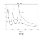
此外,影像擷取模組106包含一近紅外線(near infrared,NIR)相機106_NIR以及一可見光相機106_VL。近紅外線相機106_NIR用來產生被雷射光束(來自雷射光源102)所照射之物體之第一影像,可見光相機106_VL用來產生被可見光束(來自可見光源104_1、104_2)所照射之物體之第二影像。藉由多個照射於物體之光源,影像擷取模組106可收集物體之組織表面在不同光源下的吸光性(light absorbances),使得本發明實施例之影像處理器108可以一動態演算法,決定第一影像以及第二影像中之光斑點。動態演算法為相關於物體在不同光源下的不同光吸收度,以提升雷射光斑對比成像的解析度。In addition, the
影像處理器108可以第一影像及第二影像之一色彩圖(colormap)之一變化,決定第一影像及第二影像之一血流速度分佈。詳細而言,經由雷射光源102的照射,影像處理器108可據以獲得組織表面下約2 nm的血流資訊,而經由可見光源104_1、104_2的照射,影像處理器108可據以決定第二影像中的血氧濃度。The
進一步地,在決定第一影像以及第二影像中的血流速度分布之後,影像處理器108可用來決定第一影像以及第二影像中的一感興趣區域(region of interest,ROI)。在一實施例中,影像處理器108可自動地選取用於成像的不同感興趣區域,而被選取的感興趣區域可用來量測血流速度以及血氧濃度。Further, after determining the blood velocity distribution in the first image and the second image, the
值得注意的是,雷射光斑對比成像系統10可進一步包含一液態鏡頭(liquid lens)以快速地執行自動變焦,進而提升檢測的效率。It is worth noting that the laser spot
此外,雷射光束可監測物體的組織表面的一區域(最大至約40平方公分),例如血液微循環,並且單一微血管的一解析度可達到3微米/每一像素(um/pixel)。In addition, the laser beam can monitor an area (up to about 40 cm2) on the tissue surface of an object, such as blood microcirculation, and the resolution of a single microvessel can reach 3 micrometers per pixel (um/pixel).
雷射光斑堆疊演算法可用來根據第一影像之光斑點,決定皮質傳播抑制波形的變化。請參考第4圖及第5圖,第4圖為本發明實施例之一雷射光斑影像之示意圖,第5圖為本發明實施例之第一影像之光斑之皮質傳播抑制波形之示意圖。The laser spot stacking algorithm can be used to determine the change of cortical propagation inhibition waveform according to the light spots in the first image. Please refer to Figures 4 and 5. Figure 4 is a schematic diagram of a laser spot image according to an embodiment of the present invention, and Figure 5 is a schematic diagram of the cortical propagation suppression waveform of the first image of the spot image according to an embodiment of the present invention.
如第4圖所示,一第一光斑點SP_1之座標可以在一感興趣區域ROI_1中決定,一第二光斑點SP_2之座標可以在一感興趣區域ROI_2中決定,其中感興趣區域ROI_1是在一時間t_1決定,而感興趣區域ROI_2是在一時間t_2決定。第5圖描繪第一光斑點SP_1及第二光斑點SP_2的皮質傳播抑制波形與時間(ms)的示意圖,並且標示了第一光斑點SP_1以及第二光斑點SP_2的皮質傳播抑制波形的峰值。As shown in Figure 4, the coordinates of a first spot SP_1 can be determined in a region of interest ROI_1, and the coordinates of a second spot SP_2 can be determined in a region of interest ROI_2, wherein the region of interest ROI_1 is in A time t_1 is determined, and the ROI_2 is determined at a time t_2. Fig. 5 depicts a schematic diagram of cortical propagation inhibition waveforms and time (ms) of the first light spot SP_1 and the second light spot SP_2, and indicates the peak values of the cortical propagation inhibition waveforms of the first light spot SP_1 and the second light spot SP_2.
影像處理器108可根據第一影像中(於不同時間點獲得的)第一光斑點SP_1與第二光斑點SP_2之間之一距離D_12以及對應的第一光斑點SP_1與第二光斑點SP_2之皮質傳播抑制波形之峰值之一時間差,決定感興趣區域之一皮質傳播抑制速度V_CSD。換句話說,皮質傳播抑制速度 V_CSD可以如式(1)表示:The
V_CSD= D_12/(t2-t1)...(1)V_CSD= D_12/(t2-t1)...(1)
舉例而言,第一光斑點SP_1與第二光斑點SP_2之間之距離D_12可以於一手術實時量測,因此,皮質傳播抑制速度可根據對應於皮質傳播抑制波形之峰值之時間差決定,以提升皮質傳播抑制速度的計算效率。For example, the distance D_12 between the first light spot SP_1 and the second light spot SP_2 can be measured in real time during an operation. Therefore, the cortical propagation inhibition speed can be determined according to the time difference corresponding to the peak value of the cortical propagation inhibition waveform to improve Computational efficiency of cortical propagation inhibition velocity.
此外,影像處理器108可根據不同時間所獲得的第一影像中的光斑點SP_1、SP_2之一位置,決定感興趣區域的皮質傳播抑制之一方向。In addition, the
如此一來,本發明實施例之雷射光斑對比成像系統10即可於醫學領域上監測或量化末梢血流之資料,例如動物的大腦或傷口區域。In this way, the laser spot
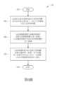
進一步地,雷射光斑對比成像系統10之一操作方法可以被歸納為一雷射光斑對比成像方法60,如第6圖所示。雷射光斑對比成像方法60包含有下列步驟:Further, an operation method of the laser spot
步驟602:開始;Step 602: start;
步驟604:由雷射光源102發射雷射光束照射物體,並且由可見光源104_1、104_2分別發射可見光束照射物體;Step 604: The
步驟606:由影像擷取模組106獲得對應於雷射光束照射物體之第一影像,以及獲得對應於可見光束照射物體之第二影像;Step 606: Obtain a first image corresponding to the object irradiated by the laser beam and obtain a second image corresponding to the object irradiated by the visible beam by the
步驟608:由影像處理器108以雷射光斑堆疊演算法處理第一影像,並且根據第一影像中所決定之至少一光斑點,決定皮質傳播抑制波形之變化;Step 608: Process the first image by the
步驟610:結束。Step 610: end.
關於上述雷射光斑對比成像方法60之操作流程,請參考上述雷射光斑對比成像系統10之實施例,在此不再贅述。For the operation process of the above-mentioned laser spot
綜上所述,本發明實施例提供一雷射光斑對比成像系統以及相關雷射光斑對比成像方法,提升計算皮質傳播抑制之效率,並且以多個波長的光束提升雷射光斑成像的解析度,進而改善計算皮質傳播抑制速度的效率。 以上所述僅為本發明之較佳實施例,凡依本發明申請專利範圍所做之均等變化與修飾,皆應屬本發明之涵蓋範圍。To sum up, the embodiment of the present invention provides a laser spot contrast imaging system and a related laser spot contrast imaging method, which improves the efficiency of calculating cortical propagation suppression, and improves the resolution of laser spot imaging with multiple wavelengths of light beams, This in turn improves the efficiency of calculating the cortical propagation inhibition velocity. The above descriptions are only preferred embodiments of the present invention, and all equivalent changes and modifications made according to the scope of the patent application of the present invention shall fall within the scope of the present invention.
10:雷射光斑對比成像系統 102:雷射光源 104_1、104_2:可見光源 106:影像擷取模組 106_VL:可見光相機 106_NIR:近紅外線相機 108:影像處理器 110:分光器 60:雷射光斑對比成像方法 602-610:步驟 D_12:距離 ROI_1、ROI_2:感興趣區域 SP_1:第一光斑點 SP_2:第二光斑點 t_1、t_2:時間 V_CSD:皮質傳播抑制速度10: Laser spot contrast imaging system 102:Laser light source 104_1, 104_2: visible light source 106: Image capture module 106_VL: Visible light camera 106_NIR: near infrared camera 108: Image processor 110: Optical splitter 60: Laser spot contrast imaging method 602-610: Steps D_12: Distance ROI_1, ROI_2: Region of interest SP_1: The first light spot SP_2: Second light spot t_1, t_2: time V_CSD: cortical spreading inhibition velocity
第1圖為本發明實施例之一雷射光斑對比成像系統之示意圖。 第2圖為本發明實施例之雷射光斑對比成像系統對一物體進行一成像過程之示意圖。 第3圖為本發明另一實施例之雷射光斑對比成像系統之示意圖。 第4圖為本發明實施例之一雷射光斑影像之示意圖。 第5圖為本發明實施例之雷射光斑影像之光斑之皮質傳播抑制波形之示意圖。 第6圖為本發明實施例之一雷射光斑對比成像方法之示意圖。FIG. 1 is a schematic diagram of a laser spot contrast imaging system according to an embodiment of the present invention. FIG. 2 is a schematic diagram of an imaging process of an object performed by the laser spot contrast imaging system according to the embodiment of the present invention. Fig. 3 is a schematic diagram of a laser spot contrast imaging system according to another embodiment of the present invention. FIG. 4 is a schematic diagram of a laser spot image according to an embodiment of the present invention. Fig. 5 is a schematic diagram of the cortical propagation inhibition waveform of the laser spot image of the embodiment of the present invention. FIG. 6 is a schematic diagram of a laser spot contrast imaging method according to an embodiment of the present invention.
10:雷射光斑對比成像系統10: Laser spot contrast imaging system
102:雷射光源102:Laser light source
104_1、104_2:可見光源104_1, 104_2: visible light source
106:影像擷取模組106: Image capture module
108:影像處理器108: Image processor
Claims (20)
Translated fromChineseApplications Claiming Priority (2)
| Application Number | Priority Date | Filing Date | Title |
|---|---|---|---|
| WOPCT/US21/63925 | 2021-12-16 | ||
| PCT/US2021/063925WO2023113809A1 (en) | 2021-12-16 | 2021-12-16 | Laser speckle contrast imaging system and laser speckle contrast imaging method thereof |
Publications (2)
| Publication Number | Publication Date |
|---|---|
| TWI800167B TWI800167B (en) | 2023-04-21 |
| TW202326235Atrue TW202326235A (en) | 2023-07-01 |
Family
ID=86773244
Family Applications (1)
| Application Number | Title | Priority Date | Filing Date |
|---|---|---|---|
| TW110147454ATWI800167B (en) | 2021-12-16 | 2021-12-17 | Laser speckle contrast imaging system and laser speckle contrast imaging method thereof |
Country Status (3)
| Country | Link |
|---|---|
| US (1) | US20250049339A1 (en) |
| TW (1) | TWI800167B (en) |
| WO (1) | WO2023113809A1 (en) |
Family Cites Families (10)
| Publication number | Priority date | Publication date | Assignee | Title |
|---|---|---|---|---|
| WO2010096453A1 (en)* | 2009-02-17 | 2010-08-26 | Board Of Regents, The University Of Texas System | Methods of producing laser speckle contrast images |
| GB0921477D0 (en)* | 2009-12-08 | 2010-01-20 | Moor Instr Ltd | Apparatus for measuring blood parameters |
| CA2765651A1 (en)* | 2011-01-24 | 2012-07-24 | Elizabeth Alice Munro | System and method for optical imaging with vertical cavity surface emitting lasers |
| US9538926B2 (en)* | 2013-12-26 | 2017-01-10 | Fundacio Institut De Ciencies Fotoniques | Speckle contrast optical tomography |
| US11395590B2 (en)* | 2014-05-01 | 2022-07-26 | Yeda Research And Development Co. Ltd. | Multimodal transcranial brain optical imaging |
| EP3359016B1 (en)* | 2015-10-09 | 2023-06-07 | Vasoptic Medical, Inc. | System and method for rapid examination of vasculature and particulate flow using laser speckle contrast imaging |
| KR101971272B1 (en)* | 2016-06-02 | 2019-08-27 | 주식회사 더웨이브톡 | A pattern structure inspection system and inspection method using the same |
| US10332315B2 (en)* | 2016-06-20 | 2019-06-25 | Magic Leap, Inc. | Augmented reality display system for evaluation and modification of neurological conditions, including visual processing and perception conditions |
| US20210283428A1 (en)* | 2019-10-07 | 2021-09-16 | The Trustees Of Columbia University In The City Of New York | Systems and methods for simultaneous monitoring of human nerve displacement |
| IL295510B2 (en)* | 2020-02-14 | 2025-08-01 | Activ Surgical Inc | Systems and methods for processing laser spot signals |
- 2021
- 2021-12-16WOPCT/US2021/063925patent/WO2023113809A1/ennot_activeCeased
- 2021-12-16USUS18/719,840patent/US20250049339A1/enactivePending
- 2021-12-17TWTW110147454Apatent/TWI800167B/enactive
Also Published As
| Publication number | Publication date |
|---|---|
| US20250049339A1 (en) | 2025-02-13 |
| TWI800167B (en) | 2023-04-21 |
| WO2023113809A1 (en) | 2023-06-22 |
Similar Documents
| Publication | Publication Date | Title |
|---|---|---|
| Jayachandran et al. | Critical review of noninvasive optical technologies for wound imaging | |
| US10362933B2 (en) | Ophthalmologic apparatus, tomographic image generation method, and program that determine an imaging region for capturing a plurality of tomographic images for generating an averaged tomographic image | |
| US8289502B2 (en) | Measurement apparatus and measurement method | |
| JP5709399B2 (en) | SUBJECT INFORMATION ACQUISITION DEVICE, ITS CONTROL METHOD, AND PROGRAM | |
| JP5528083B2 (en) | Image generating apparatus, image generating method, and program | |
| JP6108705B2 (en) | Subject information acquisition apparatus and subject information acquisition method | |
| JP2016217860A (en) | Control device, measuring device, control method, program, and storage medium | |
| US10750993B2 (en) | Tongue manifestation detecting device and tongue manifestation detecting apparatus comprising the same | |
| CN111481171A (en) | Multi-mode monitoring system and method for brain surgery | |
| US20200214602A1 (en) | Measurement apparatus | |
| CN104883974A (en) | Nir image guided targeting | |
| JP2011218149A (en) | Medical apparatus for pdt and method for controlling therapeutic light | |
| CN112153940A (en) | Blood vessel detection device and method thereof | |
| CN104887216A (en) | Multi-light-beam coherent human body skin perfusion imaging system and method | |
| US11445947B2 (en) | Methods and apparatus for measuring blood oxygenation of tissue | |
| CN116269743A (en) | Laser ablation treatment system guided by intraoperative real-time optical coherence imaging | |
| US20190142277A1 (en) | Photoacoustic apparatus and object information acquiring method | |
| CN119344701B (en) | Physiological function monitoring method, system, terminal and medium based on multi-band laser | |
| JP6486085B2 (en) | Photoacoustic wave measuring device | |
| TW202326235A (en) | Laser speckle contrast imaging system and laser speckle contrast imaging method thereof | |
| JP2009529948A (en) | Turbid medium image forming apparatus | |
| CN116615138A (en) | Apparatus, methods, and systems for providing imaging of one or more aspects of blood perfusion | |
| JP2016171910A (en) | Ultrasonic diagnostic apparatus and biopsy apparatus | |
| JP5940109B2 (en) | Image generation apparatus, propagation speed determination method, and program | |
| CN216777062U (en) | Rapid imaging system for human skin laser speckle blood flow |