TW202310157A - Processing system and methods to improve productivity of void-free and seam-free tungsten gapfill process - Google Patents
Processing system and methods to improve productivity of void-free and seam-free tungsten gapfill processDownload PDFInfo
- Publication number
- TW202310157A TW202310157ATW111113757ATW111113757ATW202310157ATW 202310157 ATW202310157 ATW 202310157ATW 111113757 ATW111113757 ATW 111113757ATW 111113757 ATW111113757 ATW 111113757ATW 202310157 ATW202310157 ATW 202310157A
- Authority
- TW
- Taiwan
- Prior art keywords
- substrate
- processing
- tungsten
- gas
- radical generator
- Prior art date
Links
Images


Classifications
- H—ELECTRICITY
- H01—ELECTRIC ELEMENTS
- H01L—SEMICONDUCTOR DEVICES NOT COVERED BY CLASS H10
- H01L21/00—Processes or apparatus adapted for the manufacture or treatment of semiconductor or solid state devices or of parts thereof
- H01L21/02—Manufacture or treatment of semiconductor devices or of parts thereof
- H01L21/04—Manufacture or treatment of semiconductor devices or of parts thereof the devices having potential barriers, e.g. a PN junction, depletion layer or carrier concentration layer
- H01L21/18—Manufacture or treatment of semiconductor devices or of parts thereof the devices having potential barriers, e.g. a PN junction, depletion layer or carrier concentration layer the devices having semiconductor bodies comprising elements of Group IV of the Periodic Table or AIIIBV compounds with or without impurities, e.g. doping materials
- H01L21/28—Manufacture of electrodes on semiconductor bodies using processes or apparatus not provided for in groups H01L21/20 - H01L21/268
- H01L21/283—Deposition of conductive or insulating materials for electrodes conducting electric current
- H01L21/285—Deposition of conductive or insulating materials for electrodes conducting electric current from a gas or vapour, e.g. condensation
- H01L21/28506—Deposition of conductive or insulating materials for electrodes conducting electric current from a gas or vapour, e.g. condensation of conductive layers
- H01L21/28512—Deposition of conductive or insulating materials for electrodes conducting electric current from a gas or vapour, e.g. condensation of conductive layers on semiconductor bodies comprising elements of Group IV of the Periodic Table
- H01L21/28556—Deposition of conductive or insulating materials for electrodes conducting electric current from a gas or vapour, e.g. condensation of conductive layers on semiconductor bodies comprising elements of Group IV of the Periodic Table by chemical means, e.g. CVD, LPCVD, PECVD, laser CVD
- C—CHEMISTRY; METALLURGY
- C23—COATING METALLIC MATERIAL; COATING MATERIAL WITH METALLIC MATERIAL; CHEMICAL SURFACE TREATMENT; DIFFUSION TREATMENT OF METALLIC MATERIAL; COATING BY VACUUM EVAPORATION, BY SPUTTERING, BY ION IMPLANTATION OR BY CHEMICAL VAPOUR DEPOSITION, IN GENERAL; INHIBITING CORROSION OF METALLIC MATERIAL OR INCRUSTATION IN GENERAL
- C23C—COATING METALLIC MATERIAL; COATING MATERIAL WITH METALLIC MATERIAL; SURFACE TREATMENT OF METALLIC MATERIAL BY DIFFUSION INTO THE SURFACE, BY CHEMICAL CONVERSION OR SUBSTITUTION; COATING BY VACUUM EVAPORATION, BY SPUTTERING, BY ION IMPLANTATION OR BY CHEMICAL VAPOUR DEPOSITION, IN GENERAL
- C23C16/00—Chemical coating by decomposition of gaseous compounds, without leaving reaction products of surface material in the coating, i.e. chemical vapour deposition [CVD] processes
- C23C16/02—Pretreatment of the material to be coated
- C23C16/0227—Pretreatment of the material to be coated by cleaning or etching
- C23C16/0236—Pretreatment of the material to be coated by cleaning or etching by etching with a reactive gas
- C—CHEMISTRY; METALLURGY
- C23—COATING METALLIC MATERIAL; COATING MATERIAL WITH METALLIC MATERIAL; CHEMICAL SURFACE TREATMENT; DIFFUSION TREATMENT OF METALLIC MATERIAL; COATING BY VACUUM EVAPORATION, BY SPUTTERING, BY ION IMPLANTATION OR BY CHEMICAL VAPOUR DEPOSITION, IN GENERAL; INHIBITING CORROSION OF METALLIC MATERIAL OR INCRUSTATION IN GENERAL
- C23C—COATING METALLIC MATERIAL; COATING MATERIAL WITH METALLIC MATERIAL; SURFACE TREATMENT OF METALLIC MATERIAL BY DIFFUSION INTO THE SURFACE, BY CHEMICAL CONVERSION OR SUBSTITUTION; COATING BY VACUUM EVAPORATION, BY SPUTTERING, BY ION IMPLANTATION OR BY CHEMICAL VAPOUR DEPOSITION, IN GENERAL
- C23C16/00—Chemical coating by decomposition of gaseous compounds, without leaving reaction products of surface material in the coating, i.e. chemical vapour deposition [CVD] processes
- C23C16/02—Pretreatment of the material to be coated
- C23C16/0272—Deposition of sub-layers, e.g. to promote the adhesion of the main coating
- C23C16/0281—Deposition of sub-layers, e.g. to promote the adhesion of the main coating of metallic sub-layers
- C—CHEMISTRY; METALLURGY
- C23—COATING METALLIC MATERIAL; COATING MATERIAL WITH METALLIC MATERIAL; CHEMICAL SURFACE TREATMENT; DIFFUSION TREATMENT OF METALLIC MATERIAL; COATING BY VACUUM EVAPORATION, BY SPUTTERING, BY ION IMPLANTATION OR BY CHEMICAL VAPOUR DEPOSITION, IN GENERAL; INHIBITING CORROSION OF METALLIC MATERIAL OR INCRUSTATION IN GENERAL
- C23C—COATING METALLIC MATERIAL; COATING MATERIAL WITH METALLIC MATERIAL; SURFACE TREATMENT OF METALLIC MATERIAL BY DIFFUSION INTO THE SURFACE, BY CHEMICAL CONVERSION OR SUBSTITUTION; COATING BY VACUUM EVAPORATION, BY SPUTTERING, BY ION IMPLANTATION OR BY CHEMICAL VAPOUR DEPOSITION, IN GENERAL
- C23C16/00—Chemical coating by decomposition of gaseous compounds, without leaving reaction products of surface material in the coating, i.e. chemical vapour deposition [CVD] processes
- C23C16/04—Coating on selected surface areas, e.g. using masks
- C23C16/045—Coating cavities or hollow spaces, e.g. interior of tubes; Infiltration of porous substrates
- C—CHEMISTRY; METALLURGY
- C23—COATING METALLIC MATERIAL; COATING MATERIAL WITH METALLIC MATERIAL; CHEMICAL SURFACE TREATMENT; DIFFUSION TREATMENT OF METALLIC MATERIAL; COATING BY VACUUM EVAPORATION, BY SPUTTERING, BY ION IMPLANTATION OR BY CHEMICAL VAPOUR DEPOSITION, IN GENERAL; INHIBITING CORROSION OF METALLIC MATERIAL OR INCRUSTATION IN GENERAL
- C23C—COATING METALLIC MATERIAL; COATING MATERIAL WITH METALLIC MATERIAL; SURFACE TREATMENT OF METALLIC MATERIAL BY DIFFUSION INTO THE SURFACE, BY CHEMICAL CONVERSION OR SUBSTITUTION; COATING BY VACUUM EVAPORATION, BY SPUTTERING, BY ION IMPLANTATION OR BY CHEMICAL VAPOUR DEPOSITION, IN GENERAL
- C23C16/00—Chemical coating by decomposition of gaseous compounds, without leaving reaction products of surface material in the coating, i.e. chemical vapour deposition [CVD] processes
- C23C16/06—Chemical coating by decomposition of gaseous compounds, without leaving reaction products of surface material in the coating, i.e. chemical vapour deposition [CVD] processes characterised by the deposition of metallic material
- C—CHEMISTRY; METALLURGY
- C23—COATING METALLIC MATERIAL; COATING MATERIAL WITH METALLIC MATERIAL; CHEMICAL SURFACE TREATMENT; DIFFUSION TREATMENT OF METALLIC MATERIAL; COATING BY VACUUM EVAPORATION, BY SPUTTERING, BY ION IMPLANTATION OR BY CHEMICAL VAPOUR DEPOSITION, IN GENERAL; INHIBITING CORROSION OF METALLIC MATERIAL OR INCRUSTATION IN GENERAL
- C23C—COATING METALLIC MATERIAL; COATING MATERIAL WITH METALLIC MATERIAL; SURFACE TREATMENT OF METALLIC MATERIAL BY DIFFUSION INTO THE SURFACE, BY CHEMICAL CONVERSION OR SUBSTITUTION; COATING BY VACUUM EVAPORATION, BY SPUTTERING, BY ION IMPLANTATION OR BY CHEMICAL VAPOUR DEPOSITION, IN GENERAL
- C23C16/00—Chemical coating by decomposition of gaseous compounds, without leaving reaction products of surface material in the coating, i.e. chemical vapour deposition [CVD] processes
- C23C16/44—Chemical coating by decomposition of gaseous compounds, without leaving reaction products of surface material in the coating, i.e. chemical vapour deposition [CVD] processes characterised by the method of coating
- C23C16/4401—Means for minimising impurities, e.g. dust, moisture or residual gas, in the reaction chamber
- C23C16/4405—Cleaning of reactor or parts inside the reactor by using reactive gases
- C—CHEMISTRY; METALLURGY
- C23—COATING METALLIC MATERIAL; COATING MATERIAL WITH METALLIC MATERIAL; CHEMICAL SURFACE TREATMENT; DIFFUSION TREATMENT OF METALLIC MATERIAL; COATING BY VACUUM EVAPORATION, BY SPUTTERING, BY ION IMPLANTATION OR BY CHEMICAL VAPOUR DEPOSITION, IN GENERAL; INHIBITING CORROSION OF METALLIC MATERIAL OR INCRUSTATION IN GENERAL
- C23C—COATING METALLIC MATERIAL; COATING MATERIAL WITH METALLIC MATERIAL; SURFACE TREATMENT OF METALLIC MATERIAL BY DIFFUSION INTO THE SURFACE, BY CHEMICAL CONVERSION OR SUBSTITUTION; COATING BY VACUUM EVAPORATION, BY SPUTTERING, BY ION IMPLANTATION OR BY CHEMICAL VAPOUR DEPOSITION, IN GENERAL
- C23C16/00—Chemical coating by decomposition of gaseous compounds, without leaving reaction products of surface material in the coating, i.e. chemical vapour deposition [CVD] processes
- C23C16/44—Chemical coating by decomposition of gaseous compounds, without leaving reaction products of surface material in the coating, i.e. chemical vapour deposition [CVD] processes characterised by the method of coating
- C23C16/455—Chemical coating by decomposition of gaseous compounds, without leaving reaction products of surface material in the coating, i.e. chemical vapour deposition [CVD] processes characterised by the method of coating characterised by the method used for introducing gases into reaction chamber or for modifying gas flows in reaction chamber
- C23C16/45523—Pulsed gas flow or change of composition over time
- C23C16/45525—Atomic layer deposition [ALD]
- C23C16/45527—Atomic layer deposition [ALD] characterized by the ALD cycle, e.g. different flows or temperatures during half-reactions, unusual pulsing sequence, use of precursor mixtures or auxiliary reactants or activations
- C23C16/45536—Use of plasma, radiation or electromagnetic fields
- C23C16/4554—Plasma being used non-continuously in between ALD reactions
- C—CHEMISTRY; METALLURGY
- C23—COATING METALLIC MATERIAL; COATING MATERIAL WITH METALLIC MATERIAL; CHEMICAL SURFACE TREATMENT; DIFFUSION TREATMENT OF METALLIC MATERIAL; COATING BY VACUUM EVAPORATION, BY SPUTTERING, BY ION IMPLANTATION OR BY CHEMICAL VAPOUR DEPOSITION, IN GENERAL; INHIBITING CORROSION OF METALLIC MATERIAL OR INCRUSTATION IN GENERAL
- C23C—COATING METALLIC MATERIAL; COATING MATERIAL WITH METALLIC MATERIAL; SURFACE TREATMENT OF METALLIC MATERIAL BY DIFFUSION INTO THE SURFACE, BY CHEMICAL CONVERSION OR SUBSTITUTION; COATING BY VACUUM EVAPORATION, BY SPUTTERING, BY ION IMPLANTATION OR BY CHEMICAL VAPOUR DEPOSITION, IN GENERAL
- C23C16/00—Chemical coating by decomposition of gaseous compounds, without leaving reaction products of surface material in the coating, i.e. chemical vapour deposition [CVD] processes
- C23C16/44—Chemical coating by decomposition of gaseous compounds, without leaving reaction products of surface material in the coating, i.e. chemical vapour deposition [CVD] processes characterised by the method of coating
- C23C16/52—Controlling or regulating the coating process
- H—ELECTRICITY
- H01—ELECTRIC ELEMENTS
- H01L—SEMICONDUCTOR DEVICES NOT COVERED BY CLASS H10
- H01L21/00—Processes or apparatus adapted for the manufacture or treatment of semiconductor or solid state devices or of parts thereof
- H01L21/02—Manufacture or treatment of semiconductor devices or of parts thereof
- H01L21/04—Manufacture or treatment of semiconductor devices or of parts thereof the devices having potential barriers, e.g. a PN junction, depletion layer or carrier concentration layer
- H01L21/18—Manufacture or treatment of semiconductor devices or of parts thereof the devices having potential barriers, e.g. a PN junction, depletion layer or carrier concentration layer the devices having semiconductor bodies comprising elements of Group IV of the Periodic Table or AIIIBV compounds with or without impurities, e.g. doping materials
- H01L21/28—Manufacture of electrodes on semiconductor bodies using processes or apparatus not provided for in groups H01L21/20 - H01L21/268
- H01L21/283—Deposition of conductive or insulating materials for electrodes conducting electric current
- H01L21/285—Deposition of conductive or insulating materials for electrodes conducting electric current from a gas or vapour, e.g. condensation
- H01L21/28506—Deposition of conductive or insulating materials for electrodes conducting electric current from a gas or vapour, e.g. condensation of conductive layers
- H01L21/28512—Deposition of conductive or insulating materials for electrodes conducting electric current from a gas or vapour, e.g. condensation of conductive layers on semiconductor bodies comprising elements of Group IV of the Periodic Table
- H01L21/28556—Deposition of conductive or insulating materials for electrodes conducting electric current from a gas or vapour, e.g. condensation of conductive layers on semiconductor bodies comprising elements of Group IV of the Periodic Table by chemical means, e.g. CVD, LPCVD, PECVD, laser CVD
- H01L21/28562—Selective deposition
- H—ELECTRICITY
- H01—ELECTRIC ELEMENTS
- H01L—SEMICONDUCTOR DEVICES NOT COVERED BY CLASS H10
- H01L21/00—Processes or apparatus adapted for the manufacture or treatment of semiconductor or solid state devices or of parts thereof
- H01L21/70—Manufacture or treatment of devices consisting of a plurality of solid state components formed in or on a common substrate or of parts thereof; Manufacture of integrated circuit devices or of parts thereof
- H01L21/71—Manufacture of specific parts of devices defined in group H01L21/70
- H01L21/768—Applying interconnections to be used for carrying current between separate components within a device comprising conductors and dielectrics
- H01L21/76838—Applying interconnections to be used for carrying current between separate components within a device comprising conductors and dielectrics characterised by the formation and the after-treatment of the conductors
- H01L21/76841—Barrier, adhesion or liner layers
- H01L21/76843—Barrier, adhesion or liner layers formed in openings in a dielectric
- H01L21/76847—Barrier, adhesion or liner layers formed in openings in a dielectric the layer being positioned within the main fill metal
- H—ELECTRICITY
- H01—ELECTRIC ELEMENTS
- H01L—SEMICONDUCTOR DEVICES NOT COVERED BY CLASS H10
- H01L21/00—Processes or apparatus adapted for the manufacture or treatment of semiconductor or solid state devices or of parts thereof
- H01L21/70—Manufacture or treatment of devices consisting of a plurality of solid state components formed in or on a common substrate or of parts thereof; Manufacture of integrated circuit devices or of parts thereof
- H01L21/71—Manufacture of specific parts of devices defined in group H01L21/70
- H01L21/768—Applying interconnections to be used for carrying current between separate components within a device comprising conductors and dielectrics
- H01L21/76838—Applying interconnections to be used for carrying current between separate components within a device comprising conductors and dielectrics characterised by the formation and the after-treatment of the conductors
- H01L21/76841—Barrier, adhesion or liner layers
- H01L21/76853—Barrier, adhesion or liner layers characterized by particular after-treatment steps
- H01L21/76855—After-treatment introducing at least one additional element into the layer
- H01L21/76856—After-treatment introducing at least one additional element into the layer by treatment in plasmas or gaseous environments, e.g. nitriding a refractory metal liner
- H—ELECTRICITY
- H01—ELECTRIC ELEMENTS
- H01L—SEMICONDUCTOR DEVICES NOT COVERED BY CLASS H10
- H01L21/00—Processes or apparatus adapted for the manufacture or treatment of semiconductor or solid state devices or of parts thereof
- H01L21/70—Manufacture or treatment of devices consisting of a plurality of solid state components formed in or on a common substrate or of parts thereof; Manufacture of integrated circuit devices or of parts thereof
- H01L21/71—Manufacture of specific parts of devices defined in group H01L21/70
- H01L21/768—Applying interconnections to be used for carrying current between separate components within a device comprising conductors and dielectrics
- H01L21/76838—Applying interconnections to be used for carrying current between separate components within a device comprising conductors and dielectrics characterised by the formation and the after-treatment of the conductors
- H01L21/76841—Barrier, adhesion or liner layers
- H01L21/76871—Layers specifically deposited to enhance or enable the nucleation of further layers, i.e. seed layers
- H01L21/76876—Layers specifically deposited to enhance or enable the nucleation of further layers, i.e. seed layers for deposition from the gas phase, e.g. CVD
- H—ELECTRICITY
- H01—ELECTRIC ELEMENTS
- H01L—SEMICONDUCTOR DEVICES NOT COVERED BY CLASS H10
- H01L21/00—Processes or apparatus adapted for the manufacture or treatment of semiconductor or solid state devices or of parts thereof
- H01L21/70—Manufacture or treatment of devices consisting of a plurality of solid state components formed in or on a common substrate or of parts thereof; Manufacture of integrated circuit devices or of parts thereof
- H01L21/71—Manufacture of specific parts of devices defined in group H01L21/70
- H01L21/768—Applying interconnections to be used for carrying current between separate components within a device comprising conductors and dielectrics
- H01L21/76838—Applying interconnections to be used for carrying current between separate components within a device comprising conductors and dielectrics characterised by the formation and the after-treatment of the conductors
- H01L21/76877—Filling of holes, grooves or trenches, e.g. vias, with conductive material
- H01L21/76879—Filling of holes, grooves or trenches, e.g. vias, with conductive material by selective deposition of conductive material in the vias, e.g. selective C.V.D. on semiconductor material, plating
- H—ELECTRICITY
- H01—ELECTRIC ELEMENTS
- H01L—SEMICONDUCTOR DEVICES NOT COVERED BY CLASS H10
- H01L23/00—Details of semiconductor or other solid state devices
- H01L23/52—Arrangements for conducting electric current within the device in operation from one component to another, i.e. interconnections, e.g. wires, lead frames
- H01L23/522—Arrangements for conducting electric current within the device in operation from one component to another, i.e. interconnections, e.g. wires, lead frames including external interconnections consisting of a multilayer structure of conductive and insulating layers inseparably formed on the semiconductor body
- H01L23/532—Arrangements for conducting electric current within the device in operation from one component to another, i.e. interconnections, e.g. wires, lead frames including external interconnections consisting of a multilayer structure of conductive and insulating layers inseparably formed on the semiconductor body characterised by the materials
- H01L23/53204—Conductive materials
- H01L23/53209—Conductive materials based on metals, e.g. alloys, metal silicides
- H01L23/53257—Conductive materials based on metals, e.g. alloys, metal silicides the principal metal being a refractory metal
- H01L23/53266—Additional layers associated with refractory-metal layers, e.g. adhesion, barrier, cladding layers
Landscapes
- Chemical & Material Sciences (AREA)
- Engineering & Computer Science (AREA)
- General Chemical & Material Sciences (AREA)
- Chemical Kinetics & Catalysis (AREA)
- Physics & Mathematics (AREA)
- Organic Chemistry (AREA)
- Metallurgy (AREA)
- Mechanical Engineering (AREA)
- Materials Engineering (AREA)
- Computer Hardware Design (AREA)
- Power Engineering (AREA)
- Microelectronics & Electronic Packaging (AREA)
- General Physics & Mathematics (AREA)
- Condensed Matter Physics & Semiconductors (AREA)
- Manufacturing & Machinery (AREA)
- Plasma & Fusion (AREA)
- Electromagnetism (AREA)
- Chemical Vapour Deposition (AREA)
- Electrodes Of Semiconductors (AREA)
- Internal Circuitry In Semiconductor Integrated Circuit Devices (AREA)
Abstract
Description
Translated fromChinese本文的實施例係關於在電子元件製造中使用的系統與方法,且更特定言之,係關於用於在半導體元件中形成鎢特徵的系統與方法。Embodiments herein relate to systems and methods used in the manufacture of electronic components, and more particularly to systems and methods for forming tungsten features in semiconductor components.
鎢(W)廣泛用於積體電路(integrated circuit; IC)元件製造中以形成導電特徵,其中需要相對低的電阻及相對高的電遷移電阻。例如,鎢可用作金屬填充材料以形成源極接點、汲極接點、金屬閘極填充、閘極接點、互連(例如,形成在介電材料層之表面中的水平特徵)及通孔(例如,經由介電材料層形成的連接安置在其上方及其下方之其他互連特徵的垂直特徵)。由於其相對低的電阻率,鎢亦常用於形成位元線及字線,此些位元線及字線用於對動態隨機存取記憶體(dynamic random-access memory; DRAM)元件之記憶體單元陣列中的個別記憶體單元定址。Tungsten (W) is widely used in the manufacture of integrated circuit (IC) devices to form conductive features, where relatively low resistance and relatively high electromigration resistance are required. For example, tungsten can be used as a metal fill material to form source contacts, drain contacts, metal gate fills, gate contacts, interconnects (e.g., horizontal features formed in the surface of a layer of dielectric material) and A via (eg, a vertical feature formed through a layer of dielectric material that connects to other interconnect features disposed above and below it). Because of its relatively low resistivity, tungsten is also commonly used to form bit lines and word lines, which are used in memory for dynamic random-access memory (DRAM) devices. Individual memory cells in the cell array are addressed.
隨著電路密度增加及元件特徵繼續縮小以滿足下一代半導體元件的需求,可靠地生產鎢特徵變得越來越具有挑戰性。諸如在習用鎢沉積製程期間形成的孔隙及接縫等問題隨著特徵尺寸的減小而被放大,且可能對元件的效能及可靠性產生不利影響,或甚至使元件無法操作。As circuit densities increase and device features continue to shrink to meet the demands of next-generation semiconductor components, it becomes increasingly challenging to reliably produce tungsten features. Problems such as voids and seams formed during conventional tungsten deposition processes are magnified as feature sizes decrease and can adversely affect device performance and reliability, or even render the device inoperable.
因此,此項技術需要解決上述問題的處理系統與方法。Therefore, what is needed in the art is a processing system and method that solves the above-mentioned problems.
本文的實施例大體上係關於電子元件製造,且更特定言之,係關於用於在半導體元件製造方案中形成實質上無孔隙與無縫式鎢特徵的系統與方法。在一些實施例中,本文所述的系統與方法提供了一種單腔室處理解決方案,此解決方案具有降低的基板處理可變性及增加的基板處理量,以促進將無縫式鎢隙填物可靠地整合至大批量製造線中。Embodiments herein relate generally to electronic component fabrication, and more particularly to systems and methods for forming substantially void-free and seamless tungsten features in semiconductor component fabrication schemes. In some embodiments, the systems and methods described herein provide a single chamber processing solution with reduced substrate processing variability and increased substrate throughput to facilitate seamless tungsten gapfill Reliable integration into high-volume manufacturing lines.
在一個實施例中,基板處理系統包括處理腔室,此處理腔室包括共同界定處理容積的腔室蓋組件、一或更多個腔室側壁及腔室底座。處理系統進一步包括與處理腔室流體耦合的氣體輸送系統,此氣體輸送系統包括第一自由基產生器及第二自由基產生器;及非暫時性電腦可讀媒體,其上儲存有指令,用於在由處理器執行時進行處理複數個基板的方法。此方法包括:(a)將基板接收至此處理容積中;(b)將此基板暴露於活化處理氣體,此活化處理氣體包括在此第一自由基產生器中形成的處理電漿的流出物;(c)將此基板暴露於第一含鎢前驅物及第一還原劑以沉積鎢隙填材料;(d)將此基板移送出此處理容積;(e)在(a)之前或之後,調節此第一自由基產生器;及(f)當順序處理的基板的數量小於或等於臨限值時,重複(a)-(e)。調節此第一自由基產生器包括:(i)使調節氣體流入此第一自由基產生器,此調節氣體包括鹵素基組分;及(ii)在第一時間段內點燃及維持此調節氣體的調節電漿。In one embodiment, a substrate processing system includes a processing chamber including a chamber lid assembly, one or more chamber sidewalls, and a chamber base that together define a processing volume. The processing system further includes a gas delivery system fluidly coupled to the processing chamber, the gas delivery system including the first free radical generator and the second free radical generator; and a non-transitory computer readable medium having stored thereon instructions for A method for processing a plurality of substrates when executed by a processor. The method includes: (a) receiving a substrate into the processing volume; (b) exposing the substrate to an activated processing gas comprising an effluent of a processing plasma formed in the first radical generator; (c) exposing the substrate to a first tungsten-containing precursor and a first reducing agent to deposit a tungsten gap-fill material; (d) moving the substrate out of the processing volume; (e) before or after (a), conditioning the first free radical generator; and (f) repeating (a)-(e) when the number of sequentially processed substrates is less than or equal to a threshold value. Conditioning the first radical generator includes: (i) flowing a conditioning gas into the first radical generator, the conditioning gas comprising a halogen-based component; and (ii) igniting and maintaining the conditioning gas for a first period of time adjustment plasma.
在一個實施例中,一種處理基板的方法包括:(a)將基板接收至處理系統的處理容積中;(b)將此基板暴露於活化處理氣體;(c)將此基板暴露於第一含鎢前驅物及第一還原劑;(d)將此基板移送出此處理容積;及(e)在(a)之前或之後,調節此第一自由基產生器;及(f)當順序處理的基板的數量小於或等於臨限值時,重複(a)-(e)。在一個實施例中,用於進行此方法的此處理系統包括:處理腔室,其包括共同界定處理容積的腔室蓋組件、一或更多個腔室側壁及腔室底座;及與此處理腔室流體耦合的氣體輸送系統,此氣體輸送系統包括第一自由基產生器及第二自由基產生器。在一個實施例中,調節此第一自由基產生器包括:(i)使調節氣體流入此第一自由基產生器,此調節氣體包括鹵素基組分;及(ii)在第一時間段內點燃及維持此調節氣體的調節電漿。在一些實施例中,此活化處理氣體包括在此第一自由基產生器中形成的處理電漿的流出物。In one embodiment, a method of processing a substrate includes: (a) receiving a substrate into a processing volume of a processing system; (b) exposing the substrate to an activating process gas; (c) exposing the substrate to a first containing a tungsten precursor and a first reducing agent; (d) moving the substrate out of the processing volume; and (e) adjusting the first radical generator before or after (a); and (f) when sequentially processed When the number of substrates is less than or equal to the threshold, repeat (a)-(e). In one embodiment, the processing system for performing the method includes: a processing chamber including a chamber lid assembly, one or more chamber sidewalls, and a chamber base that together define a processing volume; The chamber is fluidly coupled to a gas delivery system, and the gas delivery system includes a first free radical generator and a second free radical generator. In one embodiment, regulating the first free radical generator includes: (i) flowing a regulating gas into the first free radical generator, the regulating gas comprising a halogen-based component; and (ii) during a first period of time Ignite and maintain the conditioning plasma of the conditioning gas. In some embodiments, the activated process gas comprises an effluent of a process plasma formed in the first radical generator.
本文的實施例大體上係關於電子元件製造,且更特定言之,係關於用於在半導體元件製造方案中形成實質上無孔隙與無縫式鎢特徵的系統與方法。Embodiments herein relate generally to electronic component fabrication, and more particularly to systems and methods for forming substantially void-free and seamless tungsten features in semiconductor component fabrication schemes.
通常,IC元件中的鎢特徵係使用鑲嵌(金屬嵌體)製程流程形成。鑲嵌製程流程開始於在基板表面上沉積一層介電材料,圖案化介電層以形成複數個開口,及在介電層表面上沉積一層鎢材料以填充開口。通常,在沉積鎢層之前,會沉積一層諸如氮化鈦(TiN)的阻障或黏著材料以內襯於開口。阻障層及鎢層的沉積在基板區域上產生了阻障及鎢材料的覆蓋層,隨後藉由使用化學機械研磨(chemical mechanical polishing; CMP)製程將其移除。Typically, tungsten features in IC devices are formed using a damascene (metal inlay) process flow. The damascene process flow begins with depositing a layer of dielectric material on the surface of the substrate, patterning the dielectric layer to form a plurality of openings, and depositing a layer of tungsten material on the surface of the dielectric layer to fill the openings. Typically, a layer of barrier or adhesive material such as titanium nitride (TiN) is deposited to line the opening prior to depositing the tungsten layer. The deposition of the barrier layer and the tungsten layer creates a barrier and capping layer of tungsten material on the substrate area, which is subsequently removed by using a chemical mechanical polishing (CMP) process.
CMP製程使用化學及機械活性的組合來平坦化來自區域的鎢覆蓋層,此活性組合至少部分地由研磨液提供。典型的鎢CMP研磨液包含水溶液,此水溶液包括一或更多種化學活性組分及懸浮的磨料組分(例如奈米顆粒)以形成研磨漿液。化學活性組分例如藉由氧化表面形成氧化鎢薄層軟化鎢表面,且研磨組分研磨(移除)氧化鎢以暴露其下方的鎢。氧化及研磨循環在整個CMP製程中持續進行,直至鎢覆蓋層自介電層區域清除,留下嵌入的鎢特徵。The CMP process planarizes the tungsten capping layer from the regions using a combination of chemical and mechanical activity provided at least in part by the slurry. A typical tungsten CMP slurry comprises an aqueous solution that includes one or more chemically active components and suspended abrasive components such as nanoparticles to form a polishing slurry. The chemically active component softens the tungsten surface, for example by oxidizing the surface to form a thin layer of tungsten oxide, and the abrasive component grinds (removes) the tungsten oxide to expose the tungsten beneath it. Oxidation and grinding cycles are continued throughout the CMP process until the tungsten capping layer is removed from the dielectric layer region, leaving embedded tungsten features.
通常,使用習知方法沉積的鎢與下層的圖案化表面高度共形。遺憾的是,隨著元件特徵的縮小及深寬比的增加,在使用共形鎢沉積方法形成的鎢特徵中形成非期望的孔隙及接縫在很大程度上係不可避免的。所產生的非期望的孔隙及接縫(如第1A-1B圖中所示的彼等)可能會導致元件效能及可靠性問題,或者甚至係元件故障。Typically, tungsten deposited using conventional methods is highly conformal to the underlying patterned surface. Unfortunately, as device features shrink and aspect ratios increase, the formation of undesired voids and seams in tungsten features formed using conformal tungsten deposition methods is largely unavoidable. The resulting undesired voids and seams, such as those shown in FIGS. 1A-1B , can cause device performance and reliability issues, or even device failure.
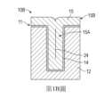
第1A圖為基板10A的橫剖面示意圖,示出了在習知鎢沉積製程期間形成的非期望的孔隙20。此處,基板10A包括圖案化表面11,此圖案化表面包含其中形成有高深寬比開口的介電層12(示出填充有鎢層15的部分)、沉積在介電層12上以內襯於開口的阻障材料層14,及沉積在阻障材料層14上的鎢層15。鎢層15使用習知沉積製程形成,例如化學氣相沉積(chemical vapor deposition; CVD)或原子層沉積(atomic layer deposition; ALD)製程,其中鎢被共形沉積(生長)在圖案化表面11上以填充開口。鎢層15在開口中形成鎢特徵15A且在圖案化表面11的區域上形成材料覆蓋層(鎢覆蓋層15B)。FIG. 1A is a schematic cross-sectional view of a
在第1A圖中,開口具有不均勻的輪廓,其在基板10A的表面處較窄且隨著開口自表面向內延伸至介電層12中而變寬(向外彎曲)。如圖所示,共形鎢層15的懸伸部分已一起生長以在開口可被完全填充之前阻斷或「夾斷」開口的入口,從而在鎢特徵15A中導致非期望的孔隙20,即缺少鎢材料。若在隨後的CMP製程期間孔隙20被打開(暴露),則研磨液可能會侵入鎢特徵15A,且研磨液的化學活性組分會導致其中的鎢材料進一步損失,例如,經由鎢材料的腐蝕及/或靜態蝕刻引起的非期望特徵取芯(主要穿孔)。此種非期望的鎢損失可能導致元件效能及可靠性問題,或者最終導致元件完全失效。即使沒有孔隙,使用習知鎢沉積製程,鎢特徵中的非期望接縫在很大程度上係不可避免的,如第1B圖所示。In FIG. 1A , the opening has a non-uniform profile that is narrow at the surface of the
第1B圖為基板10B的橫剖面示意圖,示出了在習知鎢沉積製程期間形成的非期望的接縫24。此處,圖案化表面11包括開口(填充有鎢層15的部分),隨著開口自基板10B的表面延伸至介電層12中,此開口具有實質上均勻的輪廓。開口用鎢填充,且沒有孔隙形成。儘管如此,鎢層15自開口的壁向外共形生長已導致非期望的接縫24延伸穿過形成在開口中之鎢特徵15A的中心。與第1A圖中所示的孔隙20一樣,接縫24易受鎢研磨液之化學活性組分的腐蝕,若接縫24在CMP製程期間暴露,此可能導致特徵15A中鎢材料的非期望損失。FIG. 1B is a schematic cross-sectional view of a
幸運的是,能夠進行選擇性鎢沉積從而提供自下而上的鎢隙填的新興技術已顯示出在形成下一代元件所需的實質上無孔隙與無縫式特徵方面的前景。通常,自下而上的鎢隙填製程方案採用基板處理及鎢沉積製程,此些製程對基板處理條件的微小變化均十分敏感。此種製程敏感性不均勻地影響橫跨基板表面之鎢沉積的選擇性及/或導致在同一系統內處理的多個基板之間隨時間推移或在不同系統上處理的基板之間的非期望處理變化。此外,由於(至少部分地)由於對製程條件之任何變化的高製程敏感性,選擇性鎢隙填製程的不同部分通常在不同的專用處理腔室中進行,且待處理的基板於其間被移送一或更多次。Fortunately, emerging technologies capable of selective tungsten deposition to provide bottom-up tungsten gapfill have shown promise in forming the virtually void-free and seamless features required for next-generation devices. Typically, bottom-up tungsten gapfill process schemes employ substrate processing and tungsten deposition processes, which are sensitive to small changes in substrate processing conditions. This process sensitivity non-uniformly affects the selectivity of tungsten deposition across the substrate surface and/or leads to undesired variations over time between multiple substrates processed within the same system or between substrates processed on different systems. Handle changes. In addition, due (at least in part) to the high process sensitivity to any changes in process conditions, different parts of the selective tungsten gapfill process are often performed in different dedicated processing chambers, and the substrates to be processed are transferred between them. one or more times.
遺憾的是,與習知鎢沉積製程相比,用於選擇性鎢隙填的專用處理系統及基板處理要求非期望地增加了形成鎢特徵的時間及成本。因此,本文的實施例提供了一種處理系統,此處理系統經配置為進行方法之個別態樣的組合,而無需在處理腔室之間移送基板,從而提高了本文所述之鎢隙填處理方案的總體基板處理量及能力。Unfortunately, the dedicated processing system and substrate processing requirements for selective tungsten gapfill undesirably increase the time and cost of forming tungsten features compared to conventional tungsten deposition processes. Accordingly, embodiments herein provide a processing system configured to perform combinations of individual aspects of the method without transferring substrates between processing chambers, thereby enhancing the tungsten gapfill processing scheme described herein. The overall substrate throughput and capacity.
通常,隙填處理方案包括在基板表面中形成的特徵開口中形成差動鎢沉積抑制分佈,根據抑制分佈用鎢材料填充開口,及在基板的區域表面上沉積鎢覆蓋層。形成鎢沉積抑製分佈通常包括形成鎢成核層及使用活化氮物種(例如,處理自由基)來處理鎢成核層。氮處理自由基例如藉由氮物種的吸附及/或藉由與成核層的金屬鎢反應形成氮化鎢(WN)而結合至成核層的部分中。鎢成核層的吸附氮及/或氮化表面理想地延遲(抑制)鎢成核且因此隨後在其上的鎢沉積。Typically, gapfill processing schemes include forming a differential tungsten deposition suppression profile in feature openings formed in the substrate surface, filling the openings with tungsten material according to the suppression profile, and depositing a tungsten capping layer on the area surface of the substrate. Forming a tungsten deposition inhibition profile typically includes forming a tungsten nucleation layer and treating the tungsten nucleation layer with an activated nitrogen species (eg, treating radicals). Nitrogen treatment radicals are incorporated into portions of the nucleation layer, eg, by adsorption of nitrogen species and/or by reaction with metal tungsten of the nucleation layer to form tungsten nitride (WN). The adsorbed nitrogen and/or nitrided surface of the tungsten nucleation layer ideally retards (inhibits) tungsten nucleation and thus subsequent deposition of tungsten thereon.
在一些實施例中,處理自由基藉由使用與其流體耦合的遠端電漿源遠離基板處理腔室形成。對圖案化表面之區域的期望抑制效應及在圖案化表面中形成的開口中所需的抑制分佈係藉由控制處理腔室內的處理條件(如溫度及壓力)及控制基板表面處處理自由基的濃度、通量及能量來達成。通常,處理自由基由非鹵素含氮氣體形成,如N2、NH3、NH4或其組合。In some embodiments, process radicals are formed remotely from the substrate processing chamber using a remote plasma source fluidly coupled thereto. The desired suppression effect on the area of the patterned surface and the desired suppression profile in the openings formed in the patterned surface are determined by controlling the processing conditions (such as temperature and pressure) in the processing chamber and controlling the concentration of processing radicals at the substrate surface. Concentration, flux and energy to achieve. Typically, treatment radicals are formed from non-halogen nitrogen-containing gases, such asN2 ,NH3 ,NH4 , or combinations thereof.
隙填處理方案的鎢成核及沉積製程通常包括將含鎢前驅物及還原劑流入處理腔室且將基板表面暴露於其中。含鎢前驅物及還原劑以化學氣相沉積(chemical vapor deposition; CVD)製程、脈衝CVD製程、原子層沉積(atomic layer deposition; ALD)製程或其組合中的一者在基板表面上反應以在其上沉積鎢材料。Tungsten nucleation and deposition processes for gapfill processing schemes typically include flowing tungsten-containing precursors and reducing agents into a processing chamber and exposing the substrate surface thereto. The tungsten-containing precursor and reducing agent are reacted on the surface of the substrate by chemical vapor deposition (chemical vapor deposition; CVD) process, pulse CVD process, atomic layer deposition (atomic layer deposition; ALD) process or a combination thereof. A tungsten material is deposited thereon.
不可避免地,鎢及與鎢相關的物種(非期望的鎢殘留物)亦沉積在處理腔室中除基板表面之外的表面上。若不移除,鎢殘留物係缺陷(顆粒)的來源,若轉移至基板表面,可能會導致元件故障。因此,本文所述的處理系統經配置成週期性地執行腔室清洗操作,其中使用清洗化學品自處理腔室的內表面移除非期望的鎢殘留物。此處,清洗化學品包含遠離處理腔室形成的活化鹵素物種,例如氟或氯(清洗)自由基。Inevitably, tungsten and tungsten-related species (undesired tungsten residues) are also deposited on surfaces in the processing chamber other than the substrate surface. If not removed, tungsten residues are a source of defects (particles) that can lead to component failure if transferred to the substrate surface. Accordingly, the processing systems described herein are configured to periodically perform a chamber cleaning operation in which cleaning chemicals are used to remove undesired tungsten residues from the interior surfaces of the processing chamber. Here, the cleaning chemistry comprises activated halogen species such as fluorine or chlorine (cleaning) radicals formed away from the processing chamber.
腔室清洗操作通常包括使鹵素清洗自由基流入處理腔室,使清洗自由基與鎢殘留物反應以形成揮發性鎢物種,及經由排氣口將揮發性鎢物種自處理腔室中排出。腔室清洗操作通常在基板處理之間進行,即在處理過的基板已自處理腔室中移除之後,及在隨後待處理的處理過的基板已被接收至處理腔室之前。Chamber cleaning operations generally include flowing halogen cleaning radicals into the processing chamber, reacting the cleaning radicals with tungsten residues to form volatile tungsten species, and exhausting the volatile tungsten species from the processing chamber through an exhaust port. Chamber cleaning operations are typically performed between substrate processing, ie, after a processed substrate has been removed from the processing chamber and before a processed substrate to be subsequently processed has been received into the processing chamber.
在一些實施例中,使用流體耦合至處理腔室的遠端電漿源由諸如NF3的鹵素基清洗氣體形成清洗自由基。遠離處理腔室形成清洗自由基理想地避免了對腔室部件的基於離子的損壞,如對處理腔室內部之表面的腐蝕,否則若藉由使用原位電漿在處理腔室中形成清洗自由基,則會發生此種腐蝕。因此,基於離子的損壞可理想地包含在遠端電漿源內的面向電漿的表面上,此表面可具有基於鹵素的抗電漿襯墊或塗層以保護下層材料免受基於鹵素的電漿的腐蝕作用。In some embodiments, cleaning radicals are formed from a halogen-based cleaning gas, such as NF3 , using a remote plasma source fluidly coupled to the processing chamber. Formation of cleaning radicals away from the processing chamber ideally avoids ion-based damage to chamber components, such as corrosion of surfaces inside the processing chamber, that would otherwise occur if cleaning radicals were formed in the processing chamber by using an in situ plasma. base, this corrosion will occur. Therefore, ion-based damage may ideally be contained on plasma-facing surfaces within the remote plasma source, which may have a halogen-based plasma-resistant liner or coating to protect the underlying material from halogen-based electricity. corrosion of slurry.
在一些實施例中,用於形成抑制製程中使用的處理自由基的遠端電漿源亦用於形成腔室清洗製程中使用的清洗自由基。遺憾的是,當使用相同的遠端電漿源為抑制處理製程及腔室清洗製程兩者提供自由基時,已觀察到所得抑制分佈中的非期望處理變化。非期望處理變化包括基板間抑制分佈的變化及/或跨基板表面的不均勻處理結果。In some embodiments, the remote plasma source used to form the process radicals used in the suppression process is also used to form the cleaning radicals used in the chamber cleaning process. Unfortunately, when the same remote plasma source is used to provide free radicals for both the suppression treatment process and the chamber cleaning process, undesired process variations in the resulting suppression distribution have been observed. Undesirable process variations include variations in inhibition distribution between substrates and/or non-uniform process results across the substrate surface.
在不受理論束縛的情況下,據信至少一些非期望處理變化為由鹵素基清洗電漿引起之遠端電漿源內之表面損壞的結果。進一步據信,至少一些處理變化係由暴露於基於氮的處理電漿引起之遠端電漿源內之表面的氮吸附及/或氮化引起。例如,據信在遠端電漿源之面向電漿的表面上基於鹵素離子的損傷及/或基於鹵素的污染物的積累不利地影響隨後在其中形成的氮處理自由基的解離及重組速率。使用遠端清洗電漿源形成之處理自由基之解離及重組速率的變化可能導致基板表面處活化氮物種的濃度、通量及能量的變化,從而導致不穩定的處理結果。因此,本文提供的處理系統配置有至少兩個遠端電漿源,其中第一遠端電漿源被指定用於及/或專用於產生處理自由基,而第二遠端電漿源被指定用於及/或專用於在腔室清洗操作期間產生清洗自由基。Without being bound by theory, it is believed that at least some of the undesired process changes are the result of surface damage within the remote plasma source caused by the halogen-based cleaning plasma. It is further believed that at least some of the process variation results from nitrogen adsorption and/or nitridation of surfaces within the remote plasma source caused by exposure to the nitrogen-based treatment plasma. For example, it is believed that halide ion-based damage and/or accumulation of halogen-based contaminants on the plasma-facing surface of the remote plasma source adversely affects the rate of dissociation and recombination of nitrogen-treating radicals subsequently formed therein. Variations in the dissociation and recombination rates of process radicals formed using remote cleaning plasma sources can lead to variations in the concentration, flux, and energy of activated nitrogen species at the substrate surface, leading to erratic process results. Accordingly, the treatment systems provided herein are configured with at least two remote plasma sources, wherein a first remote plasma source is designated for and/or dedicated to generating treatment radicals, and a second remote plasma source is designated Used and/or dedicated to generating cleaning radicals during chamber cleaning operations.
如下文所論述的,當與對兩者使用共同電漿源的處理系統相比時,將指定的電漿源用於各自的抑制及腔室清洗處理提供了改進的抑制處理的處理穩定性。因此,本文的實施例有益地為諸如第2A-2B圖中所示之處理系統的接縫抑制鎢隙填提供了相對低成本及高處理量的單腔室解決方案。As discussed below, the use of dedicated plasma sources for the respective suppression and chamber purge processes provides improved process stability of the suppression process when compared to processing systems that use a common plasma source for both. Accordingly, embodiments herein advantageously provide a relatively low cost and high throughput single chamber solution for seam inhibiting tungsten gapfill in processing systems such as those shown in Figures 2A-2B.
第2A-2B圖示意性地示出了可用於進行本文描述之自下而上的鎢隙填基板處理方法的處理系統200。在此,處理系統經配置為在單個處理腔室202內提供成核製程、抑制處理製程、選擇性隙填製程及覆蓋層沉積製程中的每一者所需的不同處理條件,即,無需在複數個處理腔室之間移送基板。2A-2B schematically illustrate a
如第2A圖所示,處理系統200包括處理腔室202、流體耦合至處理腔室202的氣體輸送系統204及系統控制器208。處理腔室202(在第2A圖中以橫剖面示出)包括腔室蓋組件210、一或更多個側壁212及腔室底座214,上述三者共同界定處理容積215。處理容積215流體耦合至排氣口217,如一或更多個真空泵,用於將處理容積215保持在低於大氣壓的條件下且自其中排出處理氣體及處理副產物。As shown in FIG. 2A , the
腔室蓋組件210包括蓋板216及噴淋頭218,此噴淋頭耦合至蓋板216以與其一起界定氣體分配容積219。此處,蓋板216使用一或更多個與其熱耦合的加熱器229保持在期望的溫度。噴淋頭218面向安置在處理容積215中的基板支撐組件220。如下文所論述的,基板支撐組件220經配置為在升高的基板處理位置(如圖所示)與降低的基板傳送位置(未示出)之間移動基板支撐件222,且從而移動安置在基板支撐件222上的基板230。當基板支撐組件220處於升高的基板處理位置時,噴淋頭218及基板支撐件222界定處理區域221。
在此,氣體輸送系統204經由氣體入口223(第2B圖)與處理腔室202流體連接,此氣體入口穿過蓋板216安置。藉由使用氣體輸送系統204輸送的處理或清洗氣體流經氣體入口223進入氣體分配容積219,且經由噴淋頭218中的複數個開口232(第2B圖)分配至處理區域221中。在一些實施例中,腔室蓋組件210進一步包括安置在氣體入口223與噴淋頭218之間的有孔阻障板225。在彼等實施例中,流入氣體分配容積219的氣體首先由阻障板225擴散,以與噴淋頭218一起提供進入處理區域221的更均勻或期望的氣流分佈。Here,
此處,處理氣體及處理副產物經由圍繞處理區域221的環形通道226自處理區域221徑向向外排出。環形通道226可形成在第一環形襯墊227中,此第一環形襯墊安置在一或更多個側壁212的徑向內側(如圖所示),或可形成在一或更多個側壁212中。在一些實施例中,處理腔室202包括一或更多個第二襯墊228,此些第二襯墊用於保護一或更多個側壁212或腔室底座214的內表面免受腐蝕性氣體及/或非期望材料沉積的影響。Here, process gases and process by-products are discharged radially outward from the
在一些實施例中,與處理容積215流體連通的淨化氣體源237用於使諸如氬(Ar)的化學惰性淨化氣體流入安置在基板支撐件222下方的區域中,例如,經由腔室底座214中圍繞支撐軸262的開口。在基板處理期間,淨化氣體可用於在基板支撐件222下方產生正壓區域(當與處理區域221中的壓力相比時)。通常,經由腔室底座214引入的淨化氣體自其向上流動且圍繞基板支撐件222的邊緣流動,以經由環形通道226自處理容積215中排出。淨化氣體藉由減少及/或防止材料前驅物氣體流入其中來減少基板支撐件222下方之表面上的非期望材料沉積。In some embodiments, a
此處,基板支撐組件220包括可移動的支撐軸262及基板支撐件222,此支撐軸密封地延伸穿過腔室底座214,如在腔室底座214下方的區域中由波紋管265包圍,且此基板支撐件安置在可移動的支撐軸262上。為了便於將基板移送至基板支撐件222及自基板支撐件222移出,基板支撐組件220包括升舉銷組件266,此升舉銷組件包含複數個升舉銷267,此些升舉銷耦合至升舉銷箍268或安置成與升舉銷箍268接合。此些升舉銷267可移動地安置在穿過基板支撐件222形成的開口中。當基板支撐件222安置在降低的基板移送位置(未示出)時,此些提升銷267在基板支撐件222的基板接收表面上方延伸以自該表面提升基板230且由基板處理器(未示出)提供向基板230之背側(非主動)表面的通路。當基板支撐件222處於升起或處理位置(如圖所示)時,此些升降銷267後退至基板支撐件222的基板接收表面下方以允許基板230擱置於其上。Here, the
此處,基板230經由門271(例如,安置在一或更多個側壁212中之一者中的狹縫閥)移送至基板支撐件222及自基板支撐件222移出。此處,門271周圍區域中的一或更多個開口(例如門外殼中的開口)流體耦合至淨化氣體源237,例如Ar氣體源。淨化氣體用於防止處理及清洗氣體接觸及/或使圍繞門的密封件降級,從而延長其使用壽命。Here, the
在此,基板支撐件222經配置用於真空夾持,其中藉由對基板230與基板接收表面之間的界面施加真空來將基板230固定至基板支撐件222。使用真空源272施加真空,此真空源流體耦合至形成在基板支撐件222之基板接收表面中的一或更多個通道或埠。在其他實施例中,例如,在處理腔室202經配置用於直接電漿處理的情況下,基板支撐件222可經配置用於靜電夾持。在一些實施例中,基板支撐件222包括一或更多個電極(未示出),此些電極耦合至偏置電壓電源(未示出),如連續波(continuous wave; CW) RF電源或脈衝RF電源,其供應偏置電壓。Here, the
如圖所示,基板支撐組件220具有雙區溫控系統,以在基板支撐222的不同區域內提供獨立的溫度控制。基板支撐件222的不同溫控區域對應於安置在其上之基板230的不同區域。此處,溫度控制系統包括第一加熱器263及第二加熱器264。第一加熱器263安置在基板支撐件222的中心區域,且第二加熱器264自中心區域徑向向外安置以圍繞第一加熱器263。在其他實施例中,基板支撐件222可具有單個加熱器或超過兩個加熱器。As shown, the
在一些實施例中,基板支撐組件220進一步包括環形遮蔽環235,此環形遮蔽環用於防止非期望的材料沉積在基板230的圓周斜邊上。在往返於基板支撐件222的基板移送期間,即,當基板支撐組件220安置在降低位置(未示出)時,遮蔽環235擱置在處理容積215內的環形凸台上。當基板支撐組件220安置在升高或處理位置時,基板支撐件222的徑向向外表面與環形遮蔽環235接合,使得遮蔽環235包圍安置在基板支撐件222上的基板230。此處,遮蔽環235的形狀使得當基板支撐組件220處於升高的基板處理位置時,遮蔽環235的徑向面向內部分安置在基板230的斜邊之上。In some embodiments, the
在一些實施例中,基板支撐組件220進一步包括安置在基板支撐件222上以包圍基板230的環形淨化環236。在彼等實施例中,當基板支撐組件220處於升高的基板處理位置時,遮蔽環235可安置在淨化環236上。通常,淨化環236具有複數個與淨化氣體源237流體連通的徑向面向內的開口。在基板處理期間,淨化氣體流入由遮蔽環235、淨化環236、基板支撐件222及基板230的斜邊界定的環形區域,以防止處理氣體進入環形區域且在基板230的斜邊上引起非期望的材料沉積。In some embodiments, the
在一些實施例中,處理腔室202經配置用於直接電漿處理。在彼等實施例中,噴淋頭218可電耦合至第一電源231,如RF電源,此電源提供功率以點燃及維持經由與其電容耦合而流入處理區域221之處理氣體的電漿。在一些實施例中,處理腔室202包含感應電漿產生器(未示出),且經由將RF功率感應耦合至處理氣體來形成電漿。In some embodiments, the
此處,處理系統200經有利地配置為進行無孔隙與無縫式鎢隙填製程方案的鎢成核、抑制處理及整塊鎢沉積製程中的每一者,而無需自處理腔室202移除基板230。用於進行隙填製程方案的個別製程及用於自處理腔室的內表面清除殘留物的氣體使用流體耦合至處理腔室202的氣體輸送系統204被輸送至此處理腔室。Here, the
通常,氣體輸送系統204包括一或更多個遠端電漿源,此處為第一及第二自由基產生器206A-B、沉積氣體源240及導管系統294(例如,此些導管294A-F),將自由基產生器206A-B及沉積氣體源240流體耦合至蓋組件210。氣體輸送系統204進一步包括複數個隔離閥,此處為第一及第二閥290A-B,各自安置在自由基產生器206A-B與蓋板216之間,其可用於將每個自由基產生器206A-B與處理腔室202及彼此流體隔離。Typically,
此處,自由基產生器206A-B中之每一者具有腔室主體280,此腔室主體界定各自的第一及第二電漿腔室容積281A-B(第2B圖)。每個自由基產生器206A-B耦合至各自的電源293A-B。電源293A-B用於點燃及維持自流體耦合至其的對應第一或第二氣體源287A-B輸送至電漿腔室容積281A-B之氣體的電漿282A-B。在一些實施例中,第一自由基產生器206A產生在活動303的差動抑製製程中使用的自由基(第3圖)。例如,第一自由基產生器206A可用於從自第一氣體源287A輸送至第一電漿腔室容積281A的不含鹵素的氣體混合物中點燃及維持處理電漿282A。第二自由基產生器206B可用於藉由從自第二氣體源287B輸送至第二電漿腔室容積281B的含鹵素氣體混合物中點燃及維持清洗電漿282B來產生在腔室清洗製程中使用的清洗自由基,例如活動308(第3圖)。Here, each of the
通常,氮處理自由基具有相對較短的壽命(當與鹵素清洗自由基相比時)且可表現出對與氣體輸送系統204中之表面及/或與處理電漿流出物之其他物種之碰撞的重組相對高的敏感性。因此,在本文的實施例中,第一自由基產生器206A通常定位成比第二自由基產生器206B更靠近氣體入口223,例如,以提供自第一電漿腔室容積281A至處理區域221的相對較短的行進距離。In general, nitrogen treatment radicals have relatively short lifetimes (when compared to halogen scavenging radicals) and may exhibit collisions with surfaces in the
在一些實施例中,第一自由基產生器206A亦流體耦合至第二氣體源287B,此第二氣體源將含鹵素的調節氣體輸送至第一電漿腔室容積281A以用於電漿源調節製程,如在方法300的活動309中描述的。在彼等實施例中,氣體輸送系統204可進一步包括複數個分流閥291,此些分流閥可操作以將含鹵素氣體混合物自第二氣體源287B引導至第一電漿腔室容積281A。In some embodiments, the first
可用於自由基產生器206A-B中之一或兩者的適合遠端電漿源包括射頻(radio frequency; RF)或特高頻(very high radio frequency; VHRF)電容耦合電漿(capacitively coupled plasma; CCP)源、電感耦合電漿(inductively coupled plasma; ICP)源、微波誘導(microwave-induced; MW)電漿源、電子迴旋共振(electron cyclotron resonance; ECR)腔室或高密度電漿(high-density plasma; HDP)腔室。Suitable remote plasma sources that may be used with one or both of the
如圖所示,第一自由基產生器206A藉由使用自氣體入口223向上延伸以與第一電漿腔室容積281A的出口連接的第一及第二導管294A-B流體耦合至處理腔室202。安置在第一與第二導管294A-B之間的第一閥290A用於選擇性地將第一自由基產生器206A與處理腔室202及氣體輸送系統204的其他部分流體隔離。通常,第一閥290A在腔室清洗製程(活動308)期間關閉,以防止活化清洗氣體(例如鹵素自由基)流入第一電漿腔室容積281A且損壞其表面。As shown, the first
此處,第一自由基產生器206A、第一及第二導管294A-B及第一閥290A經佈置及/或配置成使得例如藉由在導管294A-B中的一或兩個中具有彎曲部,處理電漿282A不與氣體入口223安置在直接視線中。在其他實施例中,第一電漿腔室容積281A可與氣體入口223對齊安置以提供自處理電漿282A經由氣體入口223且進入處理腔室202的直接視線。直接視線可藉由減少其間的氣相碰撞而有益地減少處理自由基的不希望的重組。Here, the first
第二自由基產生器206B藉由使用第三及第四導管294C-D流體耦合至第二導管294B,且因此耦合至處理腔室202。此處,藉由使用安置在第三與第四導管294C-D之間的第二閥290B,第二自由基產生器206B選擇性地與處理腔室202及氣體輸送系統204的其他部分隔離。如圖所示,第二自由基產生器206B、第三及第四導管294C-D及第二閥290B經佈置成使得清洗電漿282B不與第二閥290B或處理腔室安置在直接視線中。阻障清洗電漿282B與第二閥290B與清洗電漿282B與處理腔室202之間的直接視線防止鹵素離子引起之對第二閥290B及處理腔室202之部件的損壞,因此理想地延長其使用壽命。The second
在一些實施例中,電漿腔室容積281A-B中之一或兩者的面向電漿表面283由基於鹵素的抗電漿材料形成,如氧化鋁、氮化鋁、氧化矽、熔融矽石、石英、藍寶石或其組合。在一些實施例中,電漿腔室容積281A-B的面向電漿表面283包含由抗鹵素電漿材料形成的管或襯墊。在其他實施例中,面向電漿表面283具有形成在腔室主體280之內部部分上之基於鹵素的抗電漿材料的塗層或層,如形成在鋁腔室主體之內部部分上的陽極氧化鋁層。在一些實施例中,導管294A-F中的一或更多者內襯有低重組介電材料292,例如熔融矽石、石英或藍寶石,此理想地減少了遠端電漿流出物中的活化物種在被輸送至處理腔室202時的重組。In some embodiments, the plasma-facing
此處,使用第五導管294E將沉積氣體(例如含鎢前驅物及還原劑)自沉積氣體源240輸送至處理腔室202。如圖所示,第五導管294E在靠近氣體入口223的位置處耦合至第二導管294B,使得第一及第二閥290A-B可用於各自將第一及第二自由基產生器206A-B與引入處理腔室202的沉積氣體隔離。在一些實施例中,氣體輸送系統204進一步包括第六導管294F,此第六導管在靠近第二閥290B的位置處耦合至第四導管294D。第六導管294F流體耦合至旁路氣體源238,例如氬氣(Ar)氣源,此氣體源可用於週期性地清除氣體輸送系統204的部分中的非期望的殘留清洗、抑制及/或沉積氣體。Here, deposition gases, such as tungsten-containing precursors and reducing agents, are delivered from
處理系統200的操作由系統控制器208促進。系統控制器208包括可程式化中央處理單元,此處為CPU 295,其可與記憶體296(例如,非揮發性記憶體)及支援電路297一起操作。CPU 295為在工業環境中使用之任何形式的通用電腦處理器之一,如可程式化邏輯控制器(programmable logic controller; PLC),用於控制各種腔室部件及子處理器。耦合至CPU 295的記憶體296有助於處理腔室的操作。支援電路297習知地耦合至CPU 295且包含快取記憶體、時脈電路、輸入/輸出子系統、電源等及其組合,耦合至處理系統200(或第8圖的多腔室處理系統800)的各種部件以促進控制基板處理操作。Operation of the
此處,記憶體296中的指令呈程式產品的形式,諸如實施本揭示案之方法的程式。在一個實例中,本揭示案可實施為儲存在電腦可讀儲存媒體上以供電腦系統使用的程式產品。程式產品的程式定義了實施例(包括此處描述的方法)的功能。因此,電腦可讀儲存媒體在承載指導本文描述之方法之功能的電腦可讀指令時為本揭示案的實施例。Here, the instructions in
有利地,上述處理系統200可用於進行第3圖中闡述之方法300的成核、抑制、隙填沉積及覆蓋層沉積製程中的每一者,從而提供單腔室無縫式鎢填隙解決方案。Advantageously, the
第3圖為根據一實施例,示出處理基板之方法300的圖,此方法可使用處理系統200來進行。第4A-4D圖為基板400之部分的橫剖面示意圖,示出了在無孔隙與無縫式鎢隙填製程方案之不同階段之方法300的態樣。FIG. 3 is a diagram illustrating a
在活動301,方法300包括將基板接收至處理腔室202的處理容積215中。在活動302,方法300包括使用成核製程在基板上形成成核層404。第4A圖示意性地示出了其上形成有成核層404之例示性基板400的部分。At
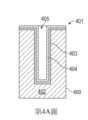
在此,基板400具有圖案化表面401,此圖案化表面包含介電材料層402,此介電材料層中形成有複數個開口405(示出一個)。在一些實施例中,此些開口405包含寬度為約1或更小,如約800 nm或更小,或約500 nm或更小且深度為約2或更多,如約3個或更多,或約4或更多的高深寬比通孔或溝槽開口中的一個或組合。在一些實施例中,開口405中的個別開口可具有約5:1或更高的深寬比(深度與寬度比),如約10:1或更高、15:1或更高,或約10:1與約40:1之間,如約15:1與約40:1之間。如圖所示,圖案化表面401包括阻障或黏著層403,例如氮化鈦(TiN)層,其沉積在介電材料層402上以共形地內襯於開口405且促進隨後的鎢成核層404的沉積。在一些實施例中,黏著層403沉積為約2埃(Å)與約100 Å之間的厚度。Here, a
在一些實施例中,方法300包括在將基板接收至處理腔室202中之前,使用多腔室處理系統800的第二處理腔室來沉積黏著層403,如第8圖所示。在一些實施例中,方法300包括在同一處理腔室202中順序地沉積黏著層403及成核層404。在一些實施例中,黏著層403用作能夠在其上進行後續整塊鎢沉積的成核層。在黏著層403用作成核層的實施例中,方法300可不包括活動302。In some embodiments,
在一些實施例中,成核層404使用原子層沉積(atomic layer deposition; ALD)製程來沉積。通常,ALD製程包括重複將基板400交替暴露於含鎢前驅物、將基板400暴露於還原劑及在交替暴露之間清洗處理區域221的循環。適合的含鎢前驅物的實例包括鹵化鎢,如六氟化鎢(WF6)、六氯化鎢(WCl6)或其組合。適合的還原劑的實例包括氫氣(H2)、硼烷(例如B2H6)及矽烷(例如SiH4、Si2H6或其組合)。在一些實施例中,含鎢前驅物包含WF6,且還原劑包含B2H6、SiH4或其組合。在一些實施例中,含鎢前驅物包含有機金屬前驅物及/或無氟前驅物,例如MDNOW(甲基環戊二烯基-二羰基亞硝基-鎢)、EDNOW(乙基環戊二烯基-二羰基亞硝基-鎢)、六羰基鎢(W(CO)6),或其組合。In some embodiments, the
在成核製程期間,處理容積215通常保持在小於約120托的壓力下,如在約900毫托與約120托之間,在約1托與約100托之間,或例如,在約1托與約50托之間。將基板400暴露於含鎢前驅物包括使含鎢前驅物以超過約10 sccm,諸如約10 sccm與約1000 sccm之間,如約10 sccm與約750 sccm之間,或約10 sccm與約500 sccm之間的流動速率自沉積氣體源240流入處理區域221。將基板400暴露於還原劑包括使還原劑以約10 sccm與約1000 sccm之間、如約10 sccm與約750 sccm之間的流動速率自沉積氣體源240流入處理區域221。應注意,本文所述的各種沉積及處理製程的流動速率係針對經配置為處理300 mm直徑基板的處理系統200。適當的縮放可用於經配置為處理不同尺寸基板的處理系統。During the nucleation process, the
此處,含鎢前驅物及還原劑各自流入處理區域221持續約0.1秒至約10秒,如約0.5秒至約5秒的持續時間。處理區域221可在交替暴露之間藉由使諸如氬(Ar)的惰性淨化氣體流入處理區域221持續約0.1秒至約10秒,如約0.5秒至約5秒的持續時間而被淨化。可自沉積氣體源240或自旁路氣體源238輸送淨化氣體。通常,成核製程的重複循環持續至成核層404的厚度在約10 Å與約200 Å之間,如在約10 Å與約150 Å之間,或在約20 Å與約150 Å之間。Here, the tungsten-containing precursor and the reducing agent each flow into the
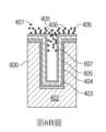
在活動303處,方法300包括處理成核層404以抑制鎢沉積在基板400的區域表面上且藉由使用差動抑制製程在此些開口405中形成差動抑制分佈。通常,形成差動抑制分佈包括將成核層404暴露於處理氣體的活化物種,例如第4B圖中所示的處理自由基406。可用於抑製製程的適合的處理氣體包括N2、H2、NH3、NH4、O2、CH4或其組合。在一些實施例中,處理氣體包含氮,例如N2、H2、NH3、NH4或其組合,且活化物種包含氮自由基,例如原子氮。在一些實施例中,處理氣體與惰性載氣例如Ar、He或其組合組合,以形成處理氣體混合物。At
在不受理論束縛的情況下,據信活化的氮物種(處理自由基406)藉由吸附活化的氮物種及/或藉由與成核層404的金屬鎢反應形成氮化鎢(WN)表面而結合至成核層404的部分中。鎢成核層404的吸附氮及/或氮化表面理想地延遲(抑制)進一步的鎢成核且因此隨後在其上的鎢沉積。Without being bound by theory, it is believed that the activated nitrogen species (processing radicals 406) form a tungsten nitride (WN) surface by adsorbing the activated nitrogen species and/or by reacting with the metallic tungsten of the
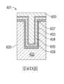
通常,控制處理自由基406擴散至此些開口405中以在特徵開口405內產生需要的抑制梯度。在此,控制處理自由基406的擴散,使得開口405之壁上的鎢生長抑制效應隨著與圖案化表面401之區域的距離增加而降低(第4B-4C圖)。結果,鎢成核更容易在特徵底部處或附近的位置建立,且一旦建立,開口405內的鎢生長(隙填材料408的沉積)自成核點(例如,自開口405的底部處沒有或低抑制的區域)加速以提供自下而上的無縫式鎢隙填。抑制梯度的方向,自高抑制區域至無抑製或低抑制區域,如箭頭417所示(第4C圖)。處理自由基406至開口405中的擴散通常至少部分地取決於開口405的尺寸及深寬比,且可藉由控制尤其係能量、通量及在一些實施例中之在圖案化表面401處之處理自由基406的方向性來調節。Typically, the diffusion of
在一些實施例中,將成核層404暴露於處理自由基406包括使用第一自由基產生器206A形成實質上不含鹵素的處理氣體混合物的處理電漿282A且使處理電漿282A的流出物流入處理區域221中。在一些實施例中,進入第一自由基產生器206A之處理氣體混合物的流動速率及因此進入處理區域221之處理電漿流出物的流動速率在約1 sccm與約3000 sccm之間,如在約1 sccm與約2500 sccm之間、約1 sccm與約2000 sccm之間、約1 sccm與約1000 sccm之間、約1 sccm與約500 sccm之間、約1 sccm與約250 sccm之間、約1 sccm與約100 sccm之間,或約1 sccm與約75 sccm之間,例如,在約1 sccm與約50 sccm之間。In some embodiments, exposing
在一些實施例中,進入第一自由基產生器206A之處理氣體混合物的流動速率在約50 sccm與約3000 sccm之間,如在約50 sccm與約2500 sccm之間,在約50 sccm與約2000 sccm之間、約50 sccm與約1000 sccm之間、約50 sccm與約500 sccm之間,或約50 sccm與約250 sccm之間。在一些實施例中,實質上不含鹵素的處理氣體(例如N2)的流動速率在約1 sccm與約200 sccm之間,如在約1 sccm與約100 sccm之間,且惰性載氣的流動速率在約50 sccm與約3000 sccm之間,諸如在約50 sccm與約2000 sccm之間,或約100 sccm與約2000 sccm之間。In some embodiments, the flow rate of the process gas mixture into the first
在一些實施例中,抑制處理製程包括將基板400暴露於處理自由基406持續約5秒或更長時間,如約6秒或更長時間、約7秒或更長時間、約8秒或更長時間、約9秒或更長時間、約10秒或更長時間,或約5秒與約120秒之間,如約5秒與約90秒之間,或約5秒與約60秒之間,或約5秒與約30秒之間,例如,約5秒與約20秒之間。In some embodiments, the suppression treatment process includes exposing the
在一些實施例中,處理氣體混合物中實質上不含鹵素的處理氣體的濃度在約0.5 vol.%與約50 vol%之間,諸如在約0.5 vol.%與約40 vol.%之間、約0.5 vol.%與約30 vol.%之間、約0.5 vol.%與約20 vol%之間,或例如,在約0.5 vol.%與約10 vol%之間,諸如在約0.5 vol.%與約5 vol.%之間。In some embodiments, the concentration of the substantially halogen-free process gas in the process gas mixture is between about 0.5 vol.% and about 50 vol.%, such as between about 0.5 vol.% and about 40 vol.%, Between about 0.5 vol.% and about 30 vol.%, between about 0.5 vol.% and about 20 vol%, or for example, between about 0.5 vol.% and about 10 vol%, such as at about 0.5 vol. % and about 5 vol.%.
在一些實施例中,例如,在實質上不含鹵素的處理氣體包含N2、NH3及/或NH4的情況下,第一自由基產生器206A可用於在300 mm直徑基板的抑制處理製程期間活化約0.02 mg與約150 mg之間的原子氮,如約0.02 mg與約150 mg之間,或約0.02mg與約100 mg之間、約0.1 mg與約100 mg之間、約0.1 mg與約100 mg之間,或約1 mg與約100 mg之間。在一些實施例中,第一自由基產生劑206A可用於在300 mm直徑基板的抑制處理製程期間活化約0.02 mg或更多的原子氮,如約0.2 mg或更多、約0.4 mg或更多、約0.6 mg或更多、約0.8 mg或更多、約1 mg或更多、約1.2 mg或更多、約1.4 mg或更多、約1.6 mg或更多、約1.8 mg或更多、約2 mg或更多、約2.2 mg或更多、約2.4mg或更多、約2.6mg或更多、約2.8mg或約3 mg或更多。適當的縮放可用於經配置為處理不同尺寸的基板的處理系統。In some embodiments, for example, where the substantially halogen-free process gas comprisesN2 ,NH3 , and/orNH4 , the first
在其他實施例中,處理自由基406可使用遠端電漿(未示出)形成,此遠端電漿被點燃且保持在由噴淋頭218與處理區域221分離之處理容積215的部分中,諸如在噴淋頭218與蓋板216之間。在彼等實施例中,活化的處理氣體可流過離子過濾器以在處理自由基406到達處理區域221及基板400的表面之前自其中實質上移除所有離子。在一些實施例中,噴淋頭218可用作離子過濾器。在其他實施例中,用於形成處理自由基的電漿為在噴淋頭218與基板400之間的處理區域221中形成的原位電漿。在一些實施例中,例如,當使用原位處理電漿時,基板400可被偏置以控制方向性及/或朝向基板表面加速由處理氣體形成的離子,例如帶電的處理自由基。In other embodiments,
在一些實施例中,抑制處理製程包括將處理容積215保持在小於約100托的壓力下,同時使活化的處理氣體流入其中。例如,在抑制處理製程期間,處理容積215可保持在小於約75托的壓力下,如小於約50托、小於約25托、小於約15托,或約0.5托與約120托之間,諸如約0.5托與約100托之間,或約0.5托與約50托之間,或例如,約1托與約10托之間。In some embodiments, inhibiting the process includes maintaining the
在活動304處,方法300包括根據活動303處的抑制處理所提供的差動抑制分佈,選擇性地將鎢隙填材料408(第4C-4D圖)沉積至此些開口405中。在一個實施例中,鎢隙填材料408使用低應力化學氣相沉積(chemical vapor deposition; CVD)製程形成,此製程包括將含鎢前驅物氣體及還原劑同時流入(共流)至處理區域221中且暴露基板400與此。用於鎢隙填CVD製程的含鎢前驅物及還原劑可包括在活動301中描述之含鎢前驅物及還原劑的任何組合。在一些實施例中,含鎢前驅物包括WF6,且還原劑包括H2。At
此處,含鎢前驅物以約50 sccm與約1000 sccm之間,或大於約50 sccm,或小於約1000 sccm,或約100 sccm與約900 sccm之間的速率流入處理區域221。還原劑以大於約500 sccm、如大於約750 sccm、大於約1000 sccm,或約500 sccm與約10000 sccm之間,諸如約1000 sccm與約9000 sccm之間,或約1000 sccm與約8000 sccm之間的速率流入處理區域221。Here, the tungsten-containing precursor flows into
在一些實施例中,選擇鎢隙填CVD製程條件以提供與習知鎢CVD製程相比具有相對低的殘餘膜應力的鎢特徵。例如,在一些實施例中,鎢隙填CVD製程包括將基板加熱至約250℃或更高的溫度,如約300℃或更高,或約250℃與約600℃之間,或約300℃與約500℃。在CVD製程期間,處理容積215通常保持在小於約500托、小於約600托、小於約500托、小於約400托,或約1托與約500托之間,如約1托與約450托之間,或約1托與約400托之間,或例如,約1托與約300托之間的壓力下。In some embodiments, the tungsten gapfill CVD process conditions are selected to provide tungsten features with relatively low residual film stress compared to conventional tungsten CVD processes. For example, in some embodiments, the tungsten gapfill CVD process includes heating the substrate to a temperature of about 250°C or higher, such as about 300°C or higher, or between about 250°C and about 600°C, or about 300°C with about 500°C. During the CVD process, the
在另一個實施例中,鎢隙填材料408在活動304處使用原子層沉積(atomic layer deposition; ALD)製程來沉積。鎢隙填ALD製程包括重複將基板400交替暴露於含鎢前驅氣體及還原劑及在交替暴露之間淨化處理區域221的循環。用於鎢隙填ALD製程的含鎢前驅物及還原劑可包括在活動301中描述的含鎢前驅物及還原劑的任何組合。在一些實施例中,含鎢前驅物包括WF6,且還原劑包括H2。In another embodiment,
此處,含鎢前驅物及還原劑各自流入處理區域221持續約0.1秒與約10秒之間,如約0.5秒與約5秒之間的持續時間。處理區域221通常在交替暴露之間藉由將例如氬(Ar)的惰性淨化氣體流入處理區域221持續約0.1秒與約10秒之間,如約0.5秒與約5秒之間的持續時間來淨化。可自沉積氣體源240或自旁路氣體源238輸送淨化氣體。Here, the tungsten-containing precursor and the reducing agent each flow into the
將基板400暴露於含鎢前驅物可包括使含鎢前驅物以約10 sccm與約1000 sccm之間的流動速率,如約100 sccm與約1000 sccm之間、約200 sccm與約1000 sccm之間、約400 sccm與約1000 sccm之間,或約500 sccm與約900 sccm之間的流動速率自沉積氣體源240流入處理區域221中。將基板400暴露於還原劑可包括使還原劑以約500 sccm與約10000sccm之間,如約500 sccm與約8000 sccm之間、約500 sccm與約5000 sccm之間,或約1000 sccm與約4000 sccm之間的流動速率自沉積氣體源240流入處理區域221。Exposing the
在一些實施例中,鎢隙填ALD製程包括將基板加熱至約250℃或更高的溫度,如約300℃或更高,或約250℃與約600℃之間,或約300℃與約500℃之間。在一些實施例中,ALD製程包括將處理容積215保持在小於約150托、小於約100托、小於約50托,例如小於約30托,或約0.5托與約50托之間,如約1托與約20托之間的壓力下。In some embodiments, the tungsten gapfill ALD process includes heating the substrate to a temperature of about 250°C or higher, such as about 300°C or higher, or between about 250°C and about 600°C, or between about 300°C and about Between 500°C. In some embodiments, the ALD process includes maintaining the
在其他實施例中,鎢隙填材料408使用脈衝CVD方法沉積,此方法包括重複循環交替地將基板400暴露於含鎢前驅氣體及還原劑而不淨化處理區域221。鎢隙填脈衝CVD方法的處理條件可與上述鎢隙填ALD製程的處理條件相同、實質上相同或在相同範圍內。In other embodiments, the
有利地,上述鎢隙填製程在由其形成的鎢材料中提供了相對低的殘餘應力。不受理論的束縛,據信由相對高的基板溫度(例如,250℃或更高)提供的增加的能量增加了對開放吸附位點的吸附原子擴散率,而相對性低的處理壓力同時減慢了鎢隙填沉積製程。與習知共形CVD製程相比,增加的吸附原子擴散率及降低的沉積速率有助於改善(更有序化)沉積鎢材料中的原子排列,從而有利地使得鎢隙填材料中的殘餘膜應力更低。例如,在一些實施例中,使用上述處理條件沉積至約1,200 Å厚度的鎢毯覆層具有小於約1600 MPa、小於約1500 MPa、小於約1400 MPa、小於約1300 MPa、小於約1200 MPa、小於約1100 MPa、小於約1000 MPa、小於約900 MPa、小於約800 MPa、小於約700 MPa,或在一些實施例中,小於約600 MPa的殘餘膜應力。Advantageously, the tungsten gap filling process described above provides relatively low residual stress in the tungsten material formed therefrom. Without being bound by theory, it is believed that the increased energy provided by relatively high substrate temperatures (e.g., 250° C. or higher) increases adatom diffusion rates to open adsorption sites, while relatively low process pressures simultaneously reduce slow down the tungsten gapfill deposition process. Compared to conventional conformal CVD processes, the increased adatom diffusivity and reduced deposition rate contribute to improved (more ordered) atomic arrangement in the deposited tungsten material, thereby advantageously making residual Membrane stress is lower. For example, in some embodiments, a blanket layer of tungsten deposited to a thickness of about 1,200 Å using the processing conditions described above has a thickness of less than about 1600 MPa, less than about 1500 MPa, less than about 1400 MPa, less than about 1300 MPa, less than about 1200 MPa, less than A residual film stress of about 1100 MPa, less than about 1000 MPa, less than about 900 MPa, less than about 800 MPa, less than about 700 MPa, or in some embodiments, less than about 600 MPa.
在典型的半導體製造方案中,化學機械研磨(chemical mechanical polishing; CMP)製程可用於在沉積鎢隙填材料408至開口405中之後自基板的區域表面移除鎢材料的覆蓋層(及安置在其下方的阻障層)。CMP製程通常依賴於化學及機械活性的組合以促進覆蓋層410的均勻移除及確定鎢覆蓋層何時自區域表面清除的終點偵測方法。鎢自區域表面的不均勻清除或未能偵測到研磨終點可導致基板表面之至少一些區域的非期望的過度研磨或研磨不足。鎢過度研磨會導致鎢自鎢特徵中非期望地移除(例如特徵取芯),此係因為CMP製程中的研磨液通常具有腐蝕性,且可能在過度研磨期間對特徵造成損壞。鎢研磨不足會導致在CMP之後殘留在區域表面上的非期望的殘餘鎢。In a typical semiconductor fabrication scheme, a chemical mechanical polishing (CMP) process may be used to remove a capping layer of tungsten material from the surface of a region of the substrate after depositing the tungsten
遺憾的是,用於藉由促進鎢的自下而上生長來提供無縫式與無孔隙鎢特徵的抑制處理亦抑制了鎢在區域表面上的生長,以防止在整塊鎢製程期間形成均勻的鎢覆蓋層。因此,本文的實施例可包括用於沉積覆蓋層的製程,此製程不同於用於沉積鎢隙填材料408的製程,以在後續CMP處理所需之基板的區域表面上提供均勻的鎢厚度。Unfortunately, the suppression treatment used to provide seamless and non-porous tungsten features by promoting bottom-up growth of tungsten also suppresses the growth of tungsten on the surface of the area to prevent the formation of uniform tungsten during the bulk tungsten process. tungsten coating. Accordingly, embodiments herein may include a process for depositing the capping layer that is different from the process for depositing the tungsten gap-
在活動305,方法300視情況包括使用第二成核製程形成第二成核層409(第4D圖)。在活動306,方法300包括使用覆蓋層製程形成覆蓋層410。第二成核製程及/或覆蓋層製程用於減少及/或消除基板之區域表面上的鎢生長抑制,其由活動303處的抑制處理製程提供。藉由減少及/或逆轉抑制效應,準備區域表面以允許鎢材料之覆蓋層的生長及/或沉積。覆蓋層410可用於促進後續化學機械研磨(chemical mechanical polishing; CMP)製程中的均勻處理。At
在一些實施例中,第二成核層409使用與在活動302中用於形成(第一)成核層404的ALD製程相同或基本相似的ALD製程或具有在活動302中針對ALD製程所列舉之範圍內之處理條件的ALD製程來沉積。當使用時,第二成核層409可沉積為約5 Å與100 Å之間,或約10 Å與80 Å之間,或例如,約20 Å與60 Å之間的厚度。In some embodiments, the
在活動306中用於沉積覆蓋層410的製程可為與在活動304中用於沉積隙填鎢材料的CVD或ALD製程相同或基本相似的CVD或ALD製程,或者具有在活動302中針對製程所列舉之範圍內之處理條件的製程。在其他實施例中,使用具有大於在活動302處用於鎢隙填製程之處理壓力的處理壓力的CVD製程來沉積覆蓋層。例如,在一些實施例中,用於沉積覆蓋層410之處理壓力與用於沉積鎢隙填材料408之處理壓力的比率為約1.25:1或更大,諸如約1.5:1或更大、約1.75:1或更大、約2:1或更大、約2.25:1或更大、約2.5:1或更大、約2.75:1或更大、約3:1或更大、約3.25:1或更大,或約3.5:1或更大。覆蓋層製程的增加的處理壓力有利地產生增加的沉積速率及減少的基板處理時間。在此,覆蓋層沉積為約500 Å與約6000 Å之間,諸如約1000 Å與約5000 Å之間的厚度。The process used to deposit
在活動307,方法300包括將處理過的基板400轉移出處理腔室202,且藉由將待處理的基板接收至202中而在活動301處重新開始。在一些實施例中,方法300進一步包括在活動308處藉由使用腔室清洗製程週期性地清洗處理基板之間的處理腔室202。腔室清洗製程用於自處理容積215的內表面移除非期望的製程殘留物,例如,累積的鎢殘留物。在一些實施例中,在處理腔室202中順序處理的基板數量大於或等於臨限值之後,諸如大於或等於2個基板或更多、3個基板或更多、5個基板或更多、7個基板或更多、9個基板或更多,或11個基板或更多之後,執行腔室清洗製程。At
在方法300的活動308中,腔室清洗製程通常包括活化遠端電漿源中的清洗氣體,且使活化的清洗氣體流入處理腔室202。通常,清洗氣體混合物包括含鹵素氣體及載氣,諸如氬氣或氦氣。可用於清洗氣體混合物之適合的含鹵素氣體的實例包括NF3、F2、SF6、CL2、CF4、C2F6、C4F8、CHF3、CF6、CCl4、C2Cl6及其組合。在一些實施例中,清洗氣體進一步包含稀釋氣體,例如Ar、He或其組合。例如,在一個實施例中,清洗氣體混合物包含NF3及Ar或He。通常,清洗氣體混合物的活化物種(例如鹵素自由基)與積聚在處理腔室202表面上的鎢殘餘物反應以形成揮發性鎢物種。揮發性鎢物種經由排氣口217自處理容積215中排出。In
在一些實施例中,進入遠端電漿源之清洗氣體混合物的流動速率,及因此進入處理容積215之活化清洗氣體混合物的流動速率為約500 sccm或更大,諸如約1000 sccm或更大、1500 sccm或更大、約2000 sccm或更大,或約2500 sccm或更大。清洗氣體混合物中含鹵素氣體的濃度通常在約5 vol.%與約95 vol.%之間,諸如在約5 vol.%與約70 vol.%之間、約10 vol.%與約95 vol.%之間,或超過約 10 vol.%。In some embodiments, the flow rate of the cleaning gas mixture into the remote plasma source, and thus the flow rate of the activated cleaning gas mixture into the
在一些實施例中,活化清洗氣體混合物流入處理容積215持續約5秒或更長、約10秒或更長、約15秒或更長的持續時間。在腔室清洗製程的一些實施例中,針對用於處理300 mm直徑基板的處理腔室,遠端電漿源可用於活化約5 mg或更多的原子鹵素,例如氟或氯,諸如約10 mg或更多、約15 mg或更多、約20 mg或更多、約25 mg或更多、約30 mg或更多、約35 mg或更多、約40 mg或更多、約45 mg或更多,或例如,約50 mg或更多。適當的縮放比例可用於處理腔室,其尺寸用於處理不同尺寸的基板。In some embodiments, the activated purge gas mixture flows into the
此處,使用遠端電漿源(例如,第二自由基產生器206B)進行腔室清洗製程,此遠端電漿源不同於用於在活動303處產生處理自由基的遠端電漿源(例如,第一自由基產生器206A)。例如,此處,腔室清洗製程包括使清洗氣體混合物流入第二自由基產生器206B,點燃及維持清洗氣體混合物的清洗電漿282B,及使清洗電漿282B的流出物流入處理容積215。通常,在處理腔室202中處理的每個基板之後執行腔室清洗操作係不合需要的,此係因為與其相關聯的基板處理能力的損失。因此,腔室清洗操作通常在腔室中已處理複數個基板之後執行,使得腔室清洗操作之間處理的平均基板數量為約2個基板或更多,諸如約5個基板或更多、約10個基板或更多、約15個基板或更多,或約20個基板或更多。Here, the chamber cleaning process is performed using a remote plasma source (eg, second
在活動303處使用用於抑制處理製程的專用電漿源(第一自由基產生器206A)理想地提供了優於將公共電漿源用於抑制處理製程及腔室清洗製程兩者之抑制處理的改進的處理穩定性。此可能係因為由處理氣體形成的電漿的腐蝕性大大低於由基於鹵素的清洗氣體形成的電漿,且因此,對第一自由基產生器206A內之表面的基於離子的損傷相對較低。儘管如此,當使用專用於形成氮處理自由基的處理電漿源時,及時觀察到基板邊緣處的處理效能至少有一些漂移,例如,基板邊緣處的抑制效能下降。Using a dedicated plasma source (first
在不受理論束縛的情況下,據信活化的氮物種可吸附在遠端電漿源的面向電漿的表面中及在遠端電漿源與處理腔室之間的導管的表面中及/或導致其氮化。吸附的氮及/或氮化表面407可降低處理電漿效率,例如,降低處理氣體的解離速率及/或促進暴露於其的活化氮物種的重組,從而導致基板表面處的自由基濃度及通量降低。因此,在一些實施例中,第一自由基產生器206A藉由自相對低流量及/或濃度的含鹵素氣體中點燃及維持電漿來週期性地調節,以自其中的表面移除吸附的氮及/或氮化物,如在活動309中所述。電漿源調節製程用於活化第一自由基產生器206A的表面,以延長隨後在其中形成之處理自由基的壽命。通常,延長處理自由基的壽命允許增加可在腔室清洗製程之間處理的基板的數量。Without being bound by theory, it is believed that the activated nitrogen species may be adsorbed in the plasma-facing surface of the remote plasma source and in the surface of the conduit between the remote plasma source and the processing chamber and/or Or lead to its nitriding. Adsorbed nitrogen and/or
在第3圖中,電漿源調節製程被示為在處理過的基板自處理腔室202轉移之後且在隨後的待處理基板被接收至其中之前進行。在其他實施例中,電漿源條件處理可在基板定位在基板支撐件222上時執行,例如,在活動303的差動抑制處理之前(如虛線所示),在活動303的差動抑制處理之後或在活動302、304、305及306處的任何各自的成核、填隙及覆蓋層製程之前、之後或同時。In FIG. 3, the plasma source conditioning process is shown as being performed after a processed substrate is transferred from the
在活動309,方法300包括使調節氣體混合物流入第一自由基產生器206A且藉由點燃及維持其電漿來活化調節氣體混合物。此處,調節氣體混合物包含含鹵素氣體及惰性載氣,諸如Ar、He或其組合。在活動308中描述了可用於調節氣體混合物的適合的含鹵素氣體。在一些實施例中,含鹵素氣體包括NF3。At
在一些實施例中,含鹵素氣體包括約0.1 vol.% 與約50 vol.%之間的調節氣體混合物,諸如約0.1 vol.%與約40 vol.%之間、約0.1 vol.%與約30 vol.%之間、約0.1 vol.%與約25 vol.%之間,或例如,0.1 vol.%與約25 vol.%之間。調節氣體混合物以約100 sccm與約2000 sccm之間的流動速率流入第一自由基產生器206A,且調節氣體混合物的電漿被點燃且保持約1秒與約30秒之間,或約1秒或更長,或約30秒或更少的時間段。在一些實施例中,含鹵素氣體可以約0.1 sccm與約30 sccm之間,諸如約0.1 sccm與約20 sccm之間、約0.1 sccm與約10 sccm之間,或約0.1 sccm與約5 sccm之間的有效流動速率被引入第一自由基產生器206A。此處,有效流動速率等於調節氣體混合物的流動速率乘以含鹵素氣體的vol.%。In some embodiments, the halogen-containing gas comprises between about 0.1 vol.% and about 50 vol.% of the conditioned gas mixture, such as between about 0.1 vol.% and about 40 vol.%, about 0.1 vol.% and about %, between about 0.1 vol.% and about 25 vol.%, or, for example, between 0.1 vol.% and about 25 vol.%. The conditioning gas mixture flows into the first
在一些實施例中,第一自由基產生器206A可用於在電漿源條件製程期間活化約0.002 mg與約40 mg之間的原子鹵素,諸如氟或氯,諸如約0.002 mg與約35 mg之間,或約0.02 mg與約30 mg之間、約0.02 mg與約25 mg之間、約0.02 mg與約20 mg之間,或約0.02 mg與約15 mg之間。在一些實施例中,第一自由基產生器206A可用於在電漿源條件製程期間活化至少約0.02 mg且不超過約40 mg的原子鹵素,諸如不超過約35 mg、不超過約30 mg、不超過約25 mg、不超過約20 mg、不超過約15 mg、不超過約10 mg,或至少約0.02 mg且不超過約8 mg的原子鹵素。In some embodiments, the first
在一些實施例中,可能需要限制第一自由基產生器206A的內表面在電漿抑制處理製程之間暴露的鹵素自由基的數量。在彼等實施例中,例如在電漿源調節製程期間在第一自由基產生器206A中產生之活化鹵素物種與在後續抑制處理製程中產生之活化氮自由基的重量比(氟(mg)/氮(mg)或氯(mg)/氮(mg))可不超過約5:1,諸如不超過約4:1、不超過約3:1,或不超過約2:1,例如不超過約1:1。In some embodiments, it may be desirable to limit the number of halogen radicals to which the interior surfaces of the first
如上所述,電漿源調節製程有益地提高了自基板至基板的處理穩定性及基板內的處理均勻性。不受理論束縛,據信在抑制處理製程中使用的活化氮物種吸附在源及腔室之間的導管表面上,且氮化表面促進隨後流經其中之活化氮物種的重組率。電漿源調節製程有利地自基板之間的表面移除氮物種,且因此有助於降低重組率及延長處理自由基的壽命。As noted above, the plasma source conditioning process beneficially improves process stability from substrate to substrate and process uniformity within the substrate. Without being bound by theory, it is believed that the activated nitrogen species used in the suppression treatment process adsorb on the surface of the conduit between the source and the chamber, and that the nitrided surface promotes the recombination rate of the activated nitrogen species subsequently flowing therethrough. The plasma source conditioning process advantageously removes nitrogen species from the surfaces between the substrates, and thus helps to reduce recombination rates and prolong the lifetime of process radicals.
第5圖為根據另一實施例,示出處理基板之方法500的圖,此方法可使用第2A-2B圖中描述的處理系統200來進行。預期方法500中描述的活動及/或處理條件中的任何一者可與方法300中描述的活動及/或處理條件結合或代替其使用。第6A-6D圖為基板400之部分的橫剖面示意圖,示出了在無孔隙與無縫式鎢隙填製程方案之不同階段之方法500的各個態樣。第6A圖示意性地示出在執行方法500的活動501-503之後的基板600。FIG. 5 is a diagram illustrating a
在活動501,方法500包括將基板600接收至處理腔室202的處理容積215中。基板600具有圖案化表面401,此圖案化表面包含介電材料層402,此介電材料層具有形成於其中的複數個開口405(示出一個),且可包括第4A-4D圖中描述之基板400的任何一種特徵及/或屬性,諸如共形黏著層403。At
在活動502,方法500包括沉積第一成核層404。可使用方法300的活動302中描述的成核製程來沉積第一成核層404。At
在活動503,方法500包括在第一成核層404上沉積共形鎢層605。可使用在活動304的選擇性隙填製程中描述之低應力CVD、ALD或脈衝CVD製程中之任何一者或組合的製程及/或製程條件來沉積共形鎢層605。此處,鎢層605沉積在未抑制的鎢成核層404上,且因此可與基板600的圖案化表面401共形,例如,以共形地內襯於形成在其中的開口405。在一些實施例中,共形鎢層605可沉積為大於約50埃(Å)的厚度,諸如約50 Å與約1000 Å之間,或約50 Å與約500 Å之間。At
在活動504,方法500包括在共形鎢層605上沉積第二成核層607(第6B圖)。在一些實施例中,第二成核層607使用與用於形成第一成核層404的相同製程或在相同處理條件範圍內的不同製程形成。At
在活動505處,方法500包括處理第二成核層607以抑制鎢沉積在基板600的區域表面上且藉由使用差動抑制製程在此些開口405中形成差動抑制分佈。活動505在第6B圖中示出且可使用方法300的活動303中描述的任何一種製程或處理條件來進行。At
在一些實施例中,方法500包括在活動504中形成第二成核層607之後及在活動505中進行抑制處理之前進行電漿源調節製程(活動509)。在彼等實施例中,第一成核層404、共形鎢層605及第二成核層607的堆疊層可保護下面的表面免受因暴露於電漿源調節製程的流出物(鹵素自由基)而引起的蝕刻及/或損壞。In some embodiments,
在活動506處,方法500包括根據活動505處的抑制處理提供的差動抑制分佈,選擇性地將整塊鎢填充材料408(第6C-6D圖)沉積至此些開口405中。活動506可使用如用於方法300的活動304中描述之選擇性隙填製程之製程或處理條件中的任何一者或組合來進行。At
在活動507處,方法500包括將基板600移送出處理腔室202,且在一些實施例中,將待處理的基板移送至處理腔室202中且重複方法500。At
在一些實施例中,方法500進一步包括在活動508處進行腔室清洗製程及/或在活動509處進行電漿源條件製程。活動508及509可使用各自在方法300的活動308及309中描述之製程、處理條件及/或操作順序中的任何一個或組合來進行。In some embodiments,
在一些實施例中,方法500進一步包括在基板600的區域表面上形成鎢材料的覆蓋層609。在一些實施例中,形成覆蓋層609包括在活動506繼續隙填製程直至克服對區域表面的抑制效應,且可在其上沉積鎢材料。在其他實施例中,覆蓋層609可使用方法300的活動305及306中描述之製程中的一者或組合來形成。In some embodiments, the
上文提供的方法及系統可用於理想地減少基板至基板的製程可變性且提高基板內處理的均勻性,同時提供增加的基板處理量及降低的基板處理成本。第7A-7B圖中所示的實驗結果證明了由上述系統與方法提供的增加的處理穩定性及改善的基板內處理均勻性。The methods and systems provided above can be used to desirably reduce substrate-to-substrate process variability and improve intra-substrate processing uniformity, while providing increased substrate throughput and reduced substrate processing costs. The experimental results shown in Figures 7A-7B demonstrate the increased process stability and improved intra-substrate process uniformity provided by the systems and methods described above.
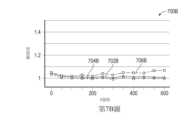
第7A圖為曲線圖700A,示出在處理系統上處理之複數個基板的處理結果,而未使用在活動309及509中描述的電漿源條件處理。第7B圖為曲線圖700B,示出使用在活動309及509中描述的電漿源調節製程處理之複數個基板的處理結果。在第7A-7B圖中的每一者中,複數個300 mm直徑的基板(每個基板上形成有鎢成核層)暴露於使用專用遠端電漿源(例如,第一自由基產生器206A)形成的氮處理自由基,之後隨後使用鎢隙填製程在其上沉積一層鎢,諸如在活動304中描述的。FIG. 7A is a
在第7A圖中,在不使用電漿源調節製程的情況下順序處理複數個基板(300個基板),使得第一自由基產生器206A在抑制處理製程之間不暴露於含鹵素的清洗氣體。在第7B圖中,複數個基板(600個基板)使用與第7A圖的基板相同的條件被順序處理,除了遠端電漿源(第一自由基產生器206A)在每個抑制處理之間使用活動309的電漿源條件製程進行調節。在每個基板的中心及在50 mm(線702A-B)、100 mm(線704A-B)及147 mm(線706A-B)的半徑處測量得到的鎢厚度。為了減少視覺混亂,未示出在每個基板中心進行的鎢厚度測量,但在半徑為50 mm(線 702A-B)及100 mm(線704A-B)之厚度測量值的約+/-2.5%範圍內。In FIG. 7A, a plurality of substrates (300 substrates) are sequentially processed without using a plasma source conditioning process such that the first
如第7A圖所示,基板706A邊緣的抑制效應(如沉積在其上之鎢材料的厚度所示)在前50個順序處理之基板的製程中降低,而自邊緣徑向向內之區域的抑制效應在基板之間保持相對穩定。相反,在第7B圖中,與自其徑向向內的區域702B及704B相比,在基板706B之邊緣處的抑制效應對於超過600個順序處理的基板保持相對穩定。As shown in FIG. 7A, the suppression effect at the edge of
在氣體入口223經由蓋板216位於中心的典型處理系統200中,用於處理基板邊緣的活化氮物種比用於處理自基板邊緣徑向向內安置之表面區域的活化物種行進更遠的距離到達基板表面。不受理論的束縛,據信較大的行進距離可導致活化物種的激發減少或活化物種在基板邊緣處的重組增加。據信,在基板邊緣處處理自由基的濃度及通量不理想地降低會導致自其接收的抑制效應相應降低。因此,據信,第7A-7B圖中展示的基板內均勻性的改善及基板間處理可變性的降低係由電漿源調節製程實現的自由基壽命增加及/或產生至少亞穩態自由基物種的結果。在本文的實施例中,亞穩態自由基物種為自由基,例如氮處理自由基,其具有約3秒或更長的壽命。In a
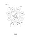
在一些實施例中,上述方法可使用多腔室處理系統800來進行,諸如第8圖中所示。此處,多腔室處理系統800包括複數個系統裝載站,此處為裝載閘站802,用於接收基板。裝載閘站802可為密封的且通常耦合至真空,諸如一或更多個真空泵,此些真空泵可用於自其中抽空氣體且將裝載閘站802保持在低於大氣壓的條件下。安置在移送腔室811中的基板處理器830用於在裝載閘站802及一或更多個處理腔室812、814、202之間移動基板230。每個處理腔室812及814可經配置為進行基板沉積製程中的至少一者,諸如循環層沉積(cyclical layer deposition; CLD)、原子層沉積(atomic layer deposition; ALD)、化學氣相沉積(chemical vapor deposition; CVD)、物理氣相沉積(physical vapor deposition; PVD)、蝕刻、脫氣、預清洗定向、退火及其他基板製程。處理系統200在第2A-2B圖中得以描述且經配置為進行本文描述的鎢隙填處理方案。In some embodiments, the methods described above may be performed using a
有利地,上述處理系統200、800經配置為在單個處理腔室202內適應成核、抑制、隙填沉積及覆蓋層沉積製程中的每一者所需的不同處理條件,而無需自其中移除基板。處理系統200進一步經配置為減少處理可變性,例如基板內處理不均勻性及基板間處理變化,從而提供理想的更寬處理窗口以實現無孔隙、無縫式及/或低應力鎢特徵。Advantageously, the
儘管前述內容係關於本揭示案的實施例,但可設計本揭示案的其他及進一步的實施例而不背離其基本範疇,且其範疇由所附發明申請專利範圍確定。While the foregoing is with respect to embodiments of the disclosure, other and further embodiments of the disclosure can be devised without departing from its basic scope, the scope of which is determined by the appended claims.
10A:基板 10B:基板 11:圖案化表面 12:介電層 14:阻障材料層 15:鎢層 15A:鎢特徵 15B:鎢覆蓋層 20:孔隙 24:接縫 200:處理系統 202:處理腔室 204:氣體輸送系統 206A:第一自由基產生器 206B:第二自由基產生器 208:系統控制器 210:腔室蓋組件 212:側壁 214:腔室底座 215:處理容積 216:蓋板 217:排氣口 218:噴淋頭 219:氣體分配容積 220:基板支撐組件 221:處理區域 222:基板支撐件 223:氣體入口 225:有孔阻障板 226:環形通道 227:第一環形襯墊 228:第二襯墊 229:加熱器 230:基板 231:第一電源 232:開口 235:環形遮蔽環 236:環形淨化環 237:淨化氣體源 238:旁路氣體源 240:沉積氣體源 262:支撐軸 263:第一加熱器 264:第二加熱器 265:波紋管 266:升舉銷組件 267:升舉銷 268:升舉銷箍 271:門 272:真空源 280:腔室主體 281A:第一電漿腔室容積 281B:第二電漿腔室容積 282A:電漿 282B:電漿 283:面向電漿表面 287A:第一氣體源 287B:第二氣體源 290A:第一閥 290B:第二閥 291:分流閥 292:低重組介電材料 293A:電源 293B:電源 294:導管系統 294A:導管 294B:導管 294C:導管 294D:導管 294E:導管 294F:導管 295:CPU 296:記憶體 297:支援電路 300:方法 301:活動 302:活動 303:活動 304:活動 305:活動 306:活動 307:活動 308:活動 309:活動 400:基板 401:圖案化表面 402:介電材料層 403:阻障或黏著層 404:第一成核層 405:開口 406:處理自由基 407:氮化表面 408:隙填材料 409:第二成核層 410:覆蓋層 417:箭頭 500:方法 501:活動 502:活動 503:活動 504:活動 505:活動 506:活動 507:活動 508:活動 509:活動 600:基板 605:共形鎢層 607:第二成核層 609:覆蓋層 700A:曲線圖 700B:曲線圖 702A:線 702B:線 704A:線 704B:線 706A:線 706B:線 800:多腔室處理系統 802:裝載閘站 811:移送腔室 812:處理腔室 814:處理腔室 830:基板處理器10A: Substrate 10B: Substrate 11: Patterned surface 12: Dielectric layer 14: barrier material layer 15: Tungsten layer 15A: Tungsten features 15B: Tungsten coating 20: porosity 24: Seams 200: Processing system 202: processing chamber 204: Gas delivery system 206A: First free radical generator 206B: Second free radical generator 208: System controller 210: chamber cover assembly 212: side wall 214: chamber base 215: processing volume 216: cover plate 217: Exhaust port 218: sprinkler head 219: gas distribution volume 220: substrate support assembly 221: processing area 222: substrate support 223: Gas inlet 225: Perforated barrier board 226: Ring channel 227: The first ring liner 228: second liner 229: heater 230: Substrate 231: The first power supply 232: opening 235: Annular shadow ring 236: ring purification ring 237: Purify gas source 238: Bypass gas source 240: Deposition gas source 262: Support shaft 263: First heater 264: second heater 265: Bellows 266:Lift pin assembly 267:Lift pin 268: Lift pin hoop 271: door 272: Vacuum source 280: chamber body 281A: Volume of the first plasma chamber 281B: Second plasma chamber volume 282A: Plasma 282B: Plasma 283: Facing the plasma surface 287A: First gas source 287B: Second gas source 290A: first valve 290B: Second valve 291: diverter valve 292: Low recombination dielectric materials 293A: power supply 293B: Power supply 294: Catheter system 294A: Conduit 294B: Conduit 294C: Conduit 294D: Catheters 294E: Conduit 294F: Conduit 295:CPU 296: memory 297: Support circuit 300: method 301: Activity 302: Activity 303: Activity 304: Activity 305: Activity 306: Activity 307: Activity 308: Activity 309: Activity 400: Substrate 401: Patterned surface 402: dielectric material layer 403: Barrier or adhesion layer 404: the first nucleation layer 405: opening 406: Dealing with Free Radicals 407: Nitrided surface 408: gap filling material 409: Second nucleation layer 410: Overlay 417:Arrow 500: method 501: Activity 502: activity 503: Activity 504: Activity 505: Activity 506: activity 507: Activity 508: Activity 509: Activity 600: Substrate 605: Conformal tungsten layer 607: Second nucleation layer 609: Overlay 700A: Curve 700B: Curve 702A: line 702B: line 704A: line 704B: line 706A: line 706B: line 800: Multi-chamber processing system 802:Loading gate station 811: transfer chamber 812: processing chamber 814: processing chamber 830: substrate processor
為了能夠詳細理解本揭示案的上述特徵,可藉由參考實施例來獲得上文簡要概括的本揭示案的更具體描述,此些實施例中的一些在隨附圖式中示出。然而,應注意,隨附圖式僅示出例示性實施例,且因此不應被視為限制其範疇,且可允許其他等效的實施例。So that the above recited features of the disclosure can be understood in detail, a more particular description of the disclosure, briefly summarized above, may be had by reference to embodiments, some of which are illustrated in the accompanying drawings. It is to be noted, however, that the appended drawings illustrate only illustrative embodiments and are therefore not to be considered limiting of its scope, for other equally effective embodiments may be permitted.
第1A-1B圖為基板之部分的橫剖面示意圖,示出了習知地形成的鎢特徵中的非期望孔隙或接縫。1A-1B are schematic cross-sectional views of portions of substrates showing undesired voids or seams in conventionally formed tungsten features.
第2A圖為根據一個實施例,可用於實施本文闡述之方法之處理系統的示意性側視圖。Figure 2A is a schematic side view of a processing system that may be used to implement the methods described herein, according to one embodiment.
第2B圖為根據一個實施例,第2A圖中所示之處理系統之部分的特寫橫剖面圖。Figure 2B is a close-up cross-sectional view of a portion of the processing system shown in Figure 2A, according to one embodiment.
第3圖為根據一個實施例,示出基板處理方法的圖,此方法可使用第2A-2B圖的處理系統來進行。Figure 3 is a diagram illustrating a substrate processing method that may be performed using the processing system of Figures 2A-2B, according to one embodiment.
第4A-4D圖為基板之部分的橫剖面示意圖,示出了第3圖中闡述之方法的各個態樣。4A-4D are schematic cross-sectional views of portions of substrates illustrating aspects of the method illustrated in FIG. 3 .
第5圖為根據另一實施例,示出基板處理方法的圖,此方法可使用第2A-2B圖的處理系統來進行。FIG. 5 is a diagram illustrating a substrate processing method that may be performed using the processing system of FIGS. 2A-2B according to another embodiment.
第6A-6D圖為基板之部分的橫剖面示意圖,示出了第5圖中闡述之方法的各個態樣。6A-6D are schematic cross-sectional views of portions of substrates illustrating aspects of the method illustrated in FIG. 5 .
第7A-7B圖為示出使用本文闡述方法形成之膜層之基板內及基板至基板處理結果的曲線圖。7A-7B are graphs showing the results of in-substrate and substrate-to-substrate processing of films formed using the methods described herein.
第8圖為根據一個實施例,例示性多腔室處理系統的示意性平面圖,此系統可用於進行本文闡述的方法。Figure 8 is a schematic plan view of an exemplary multi-chamber processing system that may be used to perform the methods set forth herein, according to one embodiment.
為了便於理解,儘可能使用相同的元件符號來指示諸圖共有的相同元件。預期一個實施例的元件及特徵可有益地結合至其他實施例中而無需進一步敘述。To facilitate understanding, the same reference numerals have been used wherever possible to refer to identical elements that are common to the figures. It is contemplated that elements and features of one embodiment may be beneficially incorporated in other embodiments without further recitation.
國內寄存資訊(請依寄存機構、日期、號碼順序註記) 無 國外寄存資訊(請依寄存國家、機構、日期、號碼順序註記) 無Domestic deposit information (please note in order of depositor, date, and number) none Overseas storage information (please note in order of storage country, institution, date, and number) none
204:氣體輸送系統204: Gas delivery system
206A:第一自由基產生器206A: First free radical generator
206B:第二自由基產生器206B: Second free radical generator
210:腔室蓋組件210: chamber cover assembly
216:蓋板216: cover plate
218:噴淋頭218: sprinkler head
223:氣體入口223: Gas inlet
225:有孔阻障板225: Perforated barrier board
229:加熱器229: heater
232:開口232: opening
238:旁路氣體源238: Bypass gas source
240:沉積氣體源240: Deposition gas source
280:腔室主體280: chamber body
281A:第一電漿腔室容積281A: Volume of the first plasma chamber
281B:第二電漿腔室容積281B: Second plasma chamber volume
282A:電漿282A: Plasma
282B:電漿282B: Plasma
283:面向電漿表面283: Facing the plasma surface
287A:第一氣體源287A: First gas source
287B:第二氣體源287B: Second gas source
290A:第一閥290A: first valve
290B:第二閥290B: Second valve
291:分流閥291: diverter valve
292:低重組介電材料292: Low recombination dielectric materials
293A:電源293A: power supply
293B:電源293B: Power supply
294A:導管294A: Conduit
294B:導管294B: Conduit
294C:導管294C: Conduit
294D:導管294D: Catheters
294E:導管294E: Conduit
294F:導管294F: Conduit
Claims (20)
Translated fromChineseApplications Claiming Priority (2)
| Application Number | Priority Date | Filing Date | Title |
|---|---|---|---|
| WOPCT/CN2021/091929 | 2021-05-06 | ||
| PCT/CN2021/091929WO2022232997A1 (en) | 2021-05-06 | 2021-05-06 | Processing system and methods to improve productivity of void-free and seam-free tungsten gapfill process |
Publications (1)
| Publication Number | Publication Date |
|---|---|
| TW202310157Atrue TW202310157A (en) | 2023-03-01 |
Family
ID=83932565
Family Applications (1)
| Application Number | Title | Priority Date | Filing Date |
|---|---|---|---|
| TW111113757ATW202310157A (en) | 2021-05-06 | 2022-04-12 | Processing system and methods to improve productivity of void-free and seam-free tungsten gapfill process |
Country Status (6)
| Country | Link |
|---|---|
| US (1) | US20240222128A1 (en) |
| JP (1) | JP2024517457A (en) |
| KR (1) | KR20240005861A (en) |
| CN (1) | CN117480586A (en) |
| TW (1) | TW202310157A (en) |
| WO (1) | WO2022232997A1 (en) |
Families Citing this family (1)
| Publication number | Priority date | Publication date | Assignee | Title |
|---|---|---|---|---|
| WO2025110419A1 (en)* | 2023-11-20 | 2025-05-30 | 주식회사 원익아이피에스 | Method for forming metal thin film |
Family Cites Families (7)
| Publication number | Priority date | Publication date | Assignee | Title |
|---|---|---|---|---|
| JP5550843B2 (en)* | 2009-03-19 | 2014-07-16 | ラピスセミコンダクタ株式会社 | Manufacturing method of semiconductor device |
| KR102100520B1 (en)* | 2012-03-27 | 2020-04-14 | 노벨러스 시스템즈, 인코포레이티드 | Tungsten feature fill with nucleation inhibition |
| CN105453230B (en)* | 2013-08-16 | 2019-06-14 | 应用材料公司 | Tungsten Deposition with Tungsten Hexafluoride (WF6) Etch Back |
| US10211099B2 (en)* | 2016-12-19 | 2019-02-19 | Lam Research Corporation | Chamber conditioning for remote plasma process |
| JP2020517103A (en)* | 2017-04-10 | 2020-06-11 | アプライド マテリアルズ インコーポレイテッドApplied Materials,Incorporated | High Deposition Rate High Quality Silicon Nitride Enabled by Remote Nitrogen Radical Source |
| CN110875245B (en)* | 2018-09-04 | 2023-06-16 | 北京北方华创微电子装备有限公司 | Thin film deposition method for filling holes or trenches |
| JP7705349B2 (en)* | 2019-02-13 | 2025-07-09 | ラム リサーチ コーポレーション | Tungsten feature filling with inhibition control |
- 2021
- 2021-05-06KRKR1020237041806Apatent/KR20240005861A/enactivePending
- 2021-05-06WOPCT/CN2021/091929patent/WO2022232997A1/ennot_activeCeased
- 2021-05-06CNCN202180098580.0Apatent/CN117480586A/enactivePending
- 2021-05-06JPJP2023568317Apatent/JP2024517457A/enactivePending
- 2021-05-06USUS18/558,388patent/US20240222128A1/enactivePending
- 2022
- 2022-04-12TWTW111113757Apatent/TW202310157A/enunknown
Also Published As
| Publication number | Publication date |
|---|---|
| WO2022232997A1 (en) | 2022-11-10 |
| US20240222128A1 (en) | 2024-07-04 |
| CN117480586A (en) | 2024-01-30 |
| JP2024517457A (en) | 2024-04-22 |
| KR20240005861A (en) | 2024-01-12 |
Similar Documents
| Publication | Publication Date | Title |
|---|---|---|
| KR102862873B1 (en) | Shadow ring lift to improve wafer edge performance | |
| TW202249207A (en) | Processing system and methods for forming void-free and seam-free tungsten features | |
| US20240368754A1 (en) | Methods for forming low resistivity tungsten features | |
| KR20240003448A (en) | Methods for Forming Void- and Seam-Free Metal Features | |
| TW202310157A (en) | Processing system and methods to improve productivity of void-free and seam-free tungsten gapfill process | |
| US20240087955A1 (en) | Integrated pvd tungsten liner and seamless cvd tungsten fill | |
| TW202043520A (en) | Methods and apparatus for filling a feature disposed in a substrate | |
| CN117730405A (en) | Masking ring lift for improved wafer edge performance | |
| US20240274407A1 (en) | Processing system and methods to co-strike plasma to enhance tungsten growth incubation delay | |
| US20240047268A1 (en) | Methods for forming multi-tier tungsten features | |
| US20230369113A1 (en) | Methods for forming multi-tier tungsten features | |
| US20240266215A1 (en) | Low stress tungsten layer deposition | |
| KR20250148662A (en) | Processing systems and methods for co-striking plasma to improve tungsten growth incubation delay | |
| CN118140301A (en) | Method for forming low resistivity tungsten features |