TW202308793A - Point-of-use ultrasonic homogenizer for cmp slurry agglomeration reduction - Google Patents
Point-of-use ultrasonic homogenizer for cmp slurry agglomeration reductionDownload PDFInfo
- Publication number
- TW202308793A TW202308793ATW111126788ATW111126788ATW202308793ATW 202308793 ATW202308793 ATW 202308793ATW 111126788 ATW111126788 ATW 111126788ATW 111126788 ATW111126788 ATW 111126788ATW 202308793 ATW202308793 ATW 202308793A
- Authority
- TW
- Taiwan
- Prior art keywords
- tube
- deblocking
- polishing
- slurry
- delivery assembly
- Prior art date
Links
- 239000002002slurrySubstances0.000titleclaimsabstractdescription137
- 238000005054agglomerationMethods0.000titledescription2
- 230000002776aggregationEffects0.000titledescription2
- 230000009467reductionEffects0.000titledescription2
- 239000012530fluidSubstances0.000claimsabstractdescription36
- 238000005498polishingMethods0.000claimsdescription177
- 239000000758substrateSubstances0.000claimsdescription44
- 238000000034methodMethods0.000claimsdescription31
- 230000007246mechanismEffects0.000claimsdescription17
- 230000005540biological transmissionEffects0.000claimsdescription13
- 238000001816coolingMethods0.000claimsdescription9
- 238000010438heat treatmentMethods0.000claimsdescription8
- 238000007517polishing processMethods0.000claimsdescription5
- 239000010453quartzSubstances0.000claimsdescription4
- VYPSYNLAJGMNEJ-UHFFFAOYSA-Nsilicon dioxideInorganic materialsO=[Si]=OVYPSYNLAJGMNEJ-UHFFFAOYSA-N0.000claimsdescription4
- 238000000429assemblyMethods0.000abstractdescription8
- 230000000712assemblyEffects0.000abstractdescription8
- 239000002245particleSubstances0.000description29
- 238000005516engineering processMethods0.000description27
- 239000000463materialSubstances0.000description12
- 230000003750conditioning effectEffects0.000description6
- 238000002604ultrasonographyMethods0.000description6
- 230000008901benefitEffects0.000description5
- 239000000126substanceSubstances0.000description5
- 230000008569processEffects0.000description4
- 238000012545processingMethods0.000description4
- 239000000243solutionSubstances0.000description4
- 239000003251chemically resistant materialSubstances0.000description3
- 229910052751metalInorganic materials0.000description3
- 239000002184metalSubstances0.000description3
- 229920000642polymerPolymers0.000description3
- 238000000151depositionMethods0.000description2
- 230000003993interactionEffects0.000description2
- 238000004519manufacturing processMethods0.000description2
- 238000012986modificationMethods0.000description2
- 230000004048modificationEffects0.000description2
- 238000012544monitoring processMethods0.000description2
- 229920011301perfluoro alkoxyl alkanePolymers0.000description2
- -1polytetrafluoroethylenePolymers0.000description2
- 239000000843powderSubstances0.000description2
- 238000006748scratchingMethods0.000description2
- 230000002393scratching effectEffects0.000description2
- 239000004065semiconductorSubstances0.000description2
- 238000003860storageMethods0.000description2
- 229910000838Al alloyInorganic materials0.000description1
- 239000004734Polyphenylene sulfideSubstances0.000description1
- XUIMIQQOPSSXEZ-UHFFFAOYSA-NSiliconChemical compound[Si]XUIMIQQOPSSXEZ-UHFFFAOYSA-N0.000description1
- 230000009471actionEffects0.000description1
- 229910052782aluminiumInorganic materials0.000description1
- XAGFODPZIPBFFR-UHFFFAOYSA-NaluminiumChemical compound[Al]XAGFODPZIPBFFR-UHFFFAOYSA-N0.000description1
- 238000013459approachMethods0.000description1
- 239000007864aqueous solutionSubstances0.000description1
- 239000006227byproductSubstances0.000description1
- 239000002826coolantSubstances0.000description1
- 230000002596correlated effectEffects0.000description1
- 230000008878couplingEffects0.000description1
- 238000010168coupling processMethods0.000description1
- 238000005859coupling reactionMethods0.000description1
- 230000008021depositionEffects0.000description1
- 238000001514detection methodMethods0.000description1
- 238000010586diagramMethods0.000description1
- 229920001971elastomerPolymers0.000description1
- 239000000806elastomerSubstances0.000description1
- 238000005485electric heatingMethods0.000description1
- 230000009969flowable effectEffects0.000description1
- 229920002313fluoropolymerPolymers0.000description1
- 239000004811fluoropolymerSubstances0.000description1
- 230000001788irregularEffects0.000description1
- 239000000203mixtureSubstances0.000description1
- 230000003287optical effectEffects0.000description1
- 239000007800oxidant agentSubstances0.000description1
- 238000000206photolithographyMethods0.000description1
- 239000004033plasticSubstances0.000description1
- 229920003023plasticPolymers0.000description1
- 229920000515polycarbonatePolymers0.000description1
- 239000004417polycarbonateSubstances0.000description1
- 229920000069polyphenylene sulfidePolymers0.000description1
- 229920001343polytetrafluoroethylenePolymers0.000description1
- 239000004810polytetrafluoroethyleneSubstances0.000description1
- 229920002635polyurethanePolymers0.000description1
- 239000004814polyurethaneSubstances0.000description1
- 238000005070samplingMethods0.000description1
- 229910052710siliconInorganic materials0.000description1
- 239000010703siliconSubstances0.000description1
- 239000010935stainless steelSubstances0.000description1
- 229910001220stainless steelInorganic materials0.000description1
- 238000010408sweepingMethods0.000description1
- 238000011144upstream manufacturingMethods0.000description1
Images


Classifications
- B—PERFORMING OPERATIONS; TRANSPORTING
- B24—GRINDING; POLISHING
- B24B—MACHINES, DEVICES, OR PROCESSES FOR GRINDING OR POLISHING; DRESSING OR CONDITIONING OF ABRADING SURFACES; FEEDING OF GRINDING, POLISHING, OR LAPPING AGENTS
- B24B37/00—Lapping machines or devices; Accessories
- B24B37/34—Accessories
- B—PERFORMING OPERATIONS; TRANSPORTING
- B01—PHYSICAL OR CHEMICAL PROCESSES OR APPARATUS IN GENERAL
- B01F—MIXING, e.g. DISSOLVING, EMULSIFYING OR DISPERSING
- B01F23/00—Mixing according to the phases to be mixed, e.g. dispersing or emulsifying
- B01F23/02—Maintaining the aggregation state of the mixed materials
- B01F23/023—Preventing sedimentation, conglomeration or agglomeration of solid ingredients during or after mixing by maintaining mixed ingredients in movement
- B—PERFORMING OPERATIONS; TRANSPORTING
- B01—PHYSICAL OR CHEMICAL PROCESSES OR APPARATUS IN GENERAL
- B01F—MIXING, e.g. DISSOLVING, EMULSIFYING OR DISPERSING
- B01F31/00—Mixers with shaking, oscillating, or vibrating mechanisms
- B01F31/80—Mixing by means of high-frequency vibrations above one kHz, e.g. ultrasonic vibrations
- B01F31/84—Mixing by means of high-frequency vibrations above one kHz, e.g. ultrasonic vibrations for material continuously moving through a tube, e.g. by deforming the tube
- B01F31/841—Mixing by means of high-frequency vibrations above one kHz, e.g. ultrasonic vibrations for material continuously moving through a tube, e.g. by deforming the tube with a vibrating element inside the tube
- B—PERFORMING OPERATIONS; TRANSPORTING
- B01—PHYSICAL OR CHEMICAL PROCESSES OR APPARATUS IN GENERAL
- B01F—MIXING, e.g. DISSOLVING, EMULSIFYING OR DISPERSING
- B01F35/00—Accessories for mixers; Auxiliary operations or auxiliary devices; Parts or details of general application
- B01F35/90—Heating or cooling systems
- B01F35/92—Heating or cooling systems for heating the outside of the receptacle, e.g. heated jackets or burners
- B—PERFORMING OPERATIONS; TRANSPORTING
- B06—GENERATING OR TRANSMITTING MECHANICAL VIBRATIONS IN GENERAL
- B06B—METHODS OR APPARATUS FOR GENERATING OR TRANSMITTING MECHANICAL VIBRATIONS OF INFRASONIC, SONIC, OR ULTRASONIC FREQUENCY, e.g. FOR PERFORMING MECHANICAL WORK IN GENERAL
- B06B1/00—Methods or apparatus for generating mechanical vibrations of infrasonic, sonic, or ultrasonic frequency
- B06B1/02—Methods or apparatus for generating mechanical vibrations of infrasonic, sonic, or ultrasonic frequency making use of electrical energy
- B06B1/06—Methods or apparatus for generating mechanical vibrations of infrasonic, sonic, or ultrasonic frequency making use of electrical energy operating with piezoelectric effect or with electrostriction
- B06B1/0607—Methods or apparatus for generating mechanical vibrations of infrasonic, sonic, or ultrasonic frequency making use of electrical energy operating with piezoelectric effect or with electrostriction using multiple elements
- B06B1/0622—Methods or apparatus for generating mechanical vibrations of infrasonic, sonic, or ultrasonic frequency making use of electrical energy operating with piezoelectric effect or with electrostriction using multiple elements on one surface
- H—ELECTRICITY
- H01—ELECTRIC ELEMENTS
- H01L—SEMICONDUCTOR DEVICES NOT COVERED BY CLASS H10
- H01L21/00—Processes or apparatus adapted for the manufacture or treatment of semiconductor or solid state devices or of parts thereof
- H01L21/02—Manufacture or treatment of semiconductor devices or of parts thereof
- H01L21/04—Manufacture or treatment of semiconductor devices or of parts thereof the devices having potential barriers, e.g. a PN junction, depletion layer or carrier concentration layer
- H01L21/18—Manufacture or treatment of semiconductor devices or of parts thereof the devices having potential barriers, e.g. a PN junction, depletion layer or carrier concentration layer the devices having semiconductor bodies comprising elements of Group IV of the Periodic Table or AIIIBV compounds with or without impurities, e.g. doping materials
- H01L21/30—Treatment of semiconductor bodies using processes or apparatus not provided for in groups H01L21/20 - H01L21/26
- H01L21/302—Treatment of semiconductor bodies using processes or apparatus not provided for in groups H01L21/20 - H01L21/26 to change their surface-physical characteristics or shape, e.g. etching, polishing, cutting
- H01L21/306—Chemical or electrical treatment, e.g. electrolytic etching
- H01L21/30625—With simultaneous mechanical treatment, e.g. mechanico-chemical polishing
- H—ELECTRICITY
- H01—ELECTRIC ELEMENTS
- H01L—SEMICONDUCTOR DEVICES NOT COVERED BY CLASS H10
- H01L22/00—Testing or measuring during manufacture or treatment; Reliability measurements, i.e. testing of parts without further processing to modify the parts as such; Structural arrangements therefor
- H01L22/20—Sequence of activities consisting of a plurality of measurements, corrections, marking or sorting steps
- B—PERFORMING OPERATIONS; TRANSPORTING
- B01—PHYSICAL OR CHEMICAL PROCESSES OR APPARATUS IN GENERAL
- B01F—MIXING, e.g. DISSOLVING, EMULSIFYING OR DISPERSING
- B01F35/00—Accessories for mixers; Auxiliary operations or auxiliary devices; Parts or details of general application
- B01F35/90—Heating or cooling systems
- B01F2035/98—Cooling
- B—PERFORMING OPERATIONS; TRANSPORTING
- B01—PHYSICAL OR CHEMICAL PROCESSES OR APPARATUS IN GENERAL
- B01F—MIXING, e.g. DISSOLVING, EMULSIFYING OR DISPERSING
- B01F35/00—Accessories for mixers; Auxiliary operations or auxiliary devices; Parts or details of general application
- B01F35/90—Heating or cooling systems
- B01F2035/99—Heating
- B—PERFORMING OPERATIONS; TRANSPORTING
- B01—PHYSICAL OR CHEMICAL PROCESSES OR APPARATUS IN GENERAL
- B01F—MIXING, e.g. DISSOLVING, EMULSIFYING OR DISPERSING
- B01F2101/00—Mixing characterised by the nature of the mixed materials or by the application field
- B01F2101/58—Mixing semiconducting materials, e.g. during semiconductor or wafer manufacturing processes
- B—PERFORMING OPERATIONS; TRANSPORTING
- B06—GENERATING OR TRANSMITTING MECHANICAL VIBRATIONS IN GENERAL
- B06B—METHODS OR APPARATUS FOR GENERATING OR TRANSMITTING MECHANICAL VIBRATIONS OF INFRASONIC, SONIC, OR ULTRASONIC FREQUENCY, e.g. FOR PERFORMING MECHANICAL WORK IN GENERAL
- B06B1/00—Methods or apparatus for generating mechanical vibrations of infrasonic, sonic, or ultrasonic frequency
- B06B1/02—Methods or apparatus for generating mechanical vibrations of infrasonic, sonic, or ultrasonic frequency making use of electrical energy
- B06B1/0292—Electrostatic transducers, e.g. electret-type
- B—PERFORMING OPERATIONS; TRANSPORTING
- B06—GENERATING OR TRANSMITTING MECHANICAL VIBRATIONS IN GENERAL
- B06B—METHODS OR APPARATUS FOR GENERATING OR TRANSMITTING MECHANICAL VIBRATIONS OF INFRASONIC, SONIC, OR ULTRASONIC FREQUENCY, e.g. FOR PERFORMING MECHANICAL WORK IN GENERAL
- B06B2201/00—Indexing scheme associated with B06B1/0207 for details covered by B06B1/0207 but not provided for in any of its subgroups
- B06B2201/70—Specific application
- B06B2201/77—Atomizers
Landscapes
- Engineering & Computer Science (AREA)
- Chemical & Material Sciences (AREA)
- Chemical Kinetics & Catalysis (AREA)
- Mechanical Engineering (AREA)
- Computer Hardware Design (AREA)
- Power Engineering (AREA)
- Microelectronics & Electronic Packaging (AREA)
- Manufacturing & Machinery (AREA)
- Physics & Mathematics (AREA)
- General Physics & Mathematics (AREA)
- Condensed Matter Physics & Semiconductors (AREA)
- Finish Polishing, Edge Sharpening, And Grinding By Specific Grinding Devices (AREA)
- Mechanical Treatment Of Semiconductor (AREA)
- Mixers With Rotating Receptacles And Mixers With Vibration Mechanisms (AREA)
- Physical Or Chemical Processes And Apparatus (AREA)
- Constituent Portions Of Griding Lathes, Driving, Sensing And Control (AREA)
- Grinding-Machine Dressing And Accessory Apparatuses (AREA)
Abstract
Description
Translated fromChinese本申請案主張標題為「POINT-OF-USE ULTRASONIC HOMOGENIZER FOR CMP SLURRY AGGLOMERATION REDUCTION」的於2021年8月18日提交的美國專利申請案第17/405,898號的權益及優先權,此專利申請案的全部內容藉由引用方式併入本文中。This application claims the benefit and priority of U.S. Patent Application No. 17/405,898, filed August 18, 2021, entitled "POINT-OF-USE ULTRASONIC HOMOGENIZER FOR CMP SLURRY AGGLOMERATION REDUCTION," which The entire contents are incorporated herein by reference.
本技術係關於半導體系統、製程、及設備。更特定言之,本技術係關於拋光在基板上沉積的膜。This technology relates to semiconductor systems, processes, and equipment. More specifically, the technology relates to polishing films deposited on substrates.
積體電路通常藉由在矽晶圓上順序沉積導電、半導電或絕緣層來在基板上形成。各種製造製程在處理步驟之間平坦化基板上的層。例如,對於某些應用,例如,拋光金屬層以在圖案化層的溝槽中形成通孔、插塞、及/或管線,平坦化覆蓋層直到暴露出圖案化層的頂表面。在其他應用(例如,平坦化介電層用於光微影)中,拋光上層直到期望厚度餘留在下層上方。Integrated circuits are usually formed on a substrate by sequentially depositing conductive, semiconductive or insulating layers on a silicon wafer. Various manufacturing processes planarize the layers on the substrate between processing steps. For example, for some applications, eg, polishing the metal layer to form vias, plugs, and/or lines in the trenches of the patterned layer, the capping layer is planarized until the top surface of the patterned layer is exposed. In other applications (eg, planarizing a dielectric layer for photolithography), the upper layer is polished until a desired thickness remains above the underlying layer.
化學機械拋光(chemical mechanical polishing; CMP)係一種常見的平坦化方法。此平坦化方法通常需要將基板安裝在載具或拋光頭上。基板的暴露表面通常抵靠旋轉拋光墊放置。載具頭在基板上提供可控負載以抵靠拋光墊推動該基板。通常將研磨拋光漿料供應到拋光墊的表面。Chemical mechanical polishing (CMP) is a common planarization method. This planarization method typically requires mounting the substrate on a carrier or polishing head. The exposed surface of the substrate is typically placed against a rotating polishing pad. The carrier head provides a controllable load on the substrate to push the substrate against the polishing pad. Typically an abrasive polishing slurry is supplied to the surface of the polishing pad.
CMP的一個問題係隨著時間推移,在拋光漿料內的研磨粒子可結塊以形成更粗糙的粒子。此等粗糙粒子可不均勻地拋光膜的表面。此外,粗糙粒子可刮擦膜表面。One problem with CMP is that over time the abrasive particles within the polishing slurry can agglomerate to form coarser particles. Such rough particles may unevenly polish the surface of the film. In addition, rough particles can scratch the film surface.
因此,需要可以用於更均勻地拋光基板的經改進的系統及方法。此等及其他需要由本技術解決。Accordingly, there is a need for improved systems and methods that can be used to more uniformly polish substrates. These and other needs are addressed by the present technology.
示例性漿料遞送組件可包括漿料流體源。組件可包括具有內腔入口及內腔出口的漿料遞送內腔。內腔入口可與漿料流體源的出口流體耦接。組件可包括與內腔出口流體耦接的解塊管。解塊管可包括管入口及管出口。組件可包括與解塊管耦接的一或多個超聲波換能器。An exemplary slurry delivery assembly can include a slurry fluid source. The assembly can include a slurry delivery lumen having a lumen inlet and a lumen outlet. The lumen inlet may be fluidly coupled to the outlet of the slurry fluid source. The assembly may include a deblocking tube fluidly coupled to the lumen outlet. The deblocking tube may include a tube inlet and a tube outlet. The assembly may include one or more ultrasonic transducers coupled to the deblocking tube.
在一些實施例中,一或多個超聲波換能器可包括壓電換能器。一或多個超聲波換能器可抵靠解塊管的外表面定位。組件可包括插入解塊管的外表面與一或多個超聲波換能器之間的配接器。一或多個超聲波換能器可沿著解塊管的長度均勻地間隔開。一或多個超聲波換能器可在解塊管的多個側面上定位。組件可包括與解塊管耦接的支撐臂。解塊管靠近管出口的內端可係漏斗形的。In some embodiments, the one or more ultrasonic transducers may include piezoelectric transducers. One or more ultrasonic transducers may be positioned against the outer surface of the deblocking tube. The assembly may include an adapter inserted between the outer surface of the deblocking tube and the one or more ultrasonic transducers. One or more ultrasonic transducers may be evenly spaced along the length of the deblocking tube. One or more ultrasonic transducers may be positioned on multiple sides of the deblocking tube. The assembly may include a support arm coupled to the deblocking tube. The inner end of the deblocking tube near the outlet of the tube may be funnel-shaped.
本技術的一些實施例可涵蓋漿料遞送組件。組件可包括解塊管。解塊管可包括入口。解塊管可包括出口。解塊管可包括在入口與出口之間設置的中間區域。中間區域可具有與入口及出口相比較大的直徑。組件可包括與解塊管耦接的一或多個超聲波換能器。Some embodiments of the present technology may encompass slurry delivery assemblies. Assemblies may include deblocking tubes. The deblocking tube may include an inlet. The deblocking tube may include an outlet. The deblocking tube may include an intermediate region disposed between the inlet and the outlet. The intermediate region may have a larger diameter than the inlet and outlet. The assembly may include one or more ultrasonic transducers coupled to the deblocking tube.
在一些實施例中,組件可包括具有近端及遠端的波傳輸桿。近端可與一或多個超聲波換能器耦接並且遠端可突出到解塊管的中間區域的內部。波傳輸桿可至少部分沿著解塊管的中間區域的長度延伸。組件可包括靠近解塊管設置的溫度控制機構。溫度控制機構可包括加熱裝置及冷卻裝置中的一者或兩者。組件可包括與解塊管的中間區域耦接的熱電偶。熱電偶可在解塊管的中間區域的內部設置。組件可包括與出口耦接的遞送噴口。In some embodiments, an assembly may include a wave transmission rod having a proximal end and a distal end. The proximal end may be coupled to one or more ultrasound transducers and the distal end may protrude inside the middle region of the deblocking tube. The wave transmission rod may extend at least partially along the length of the middle region of the deblocking tube. The assembly may include a temperature control mechanism positioned adjacent to the deblocking tube. The temperature control mechanism may include one or both of a heating device and a cooling device. The assembly may include a thermocouple coupled to the middle region of the deblocking tube. A thermocouple may be located inside the middle region of the deblocking tube. The assembly can include a delivery spout coupled to the outlet.
本技術的一些實施例可涵蓋拋光基板的方法。方法可包括使拋光漿料流動到解塊管中。方法可包括在拋光漿料穿過解塊管流動時致動與解塊管耦接的一或多個超聲波換能器。方法可包括將拋光漿料遞送到拋光墊。方法可包括在拋光墊頂上拋光基板。Some embodiments of the present technology may encompass methods of polishing a substrate. The method may include flowing a polishing slurry into a deblocking tube. The method may include actuating one or more ultrasonic transducers coupled to the deblocking tube while the polishing slurry flows through the deblocking tube. Methods can include delivering a polishing slurry to a polishing pad. Methods can include polishing a substrate atop a polishing pad.
在一些實施例中,方法可包括監控解塊管及拋光漿料中的一者或兩者的溫度。方法可包括基於溫度調節靠近解塊管定位的溫度控制機構。解塊管可包括石英。In some embodiments, the method can include monitoring the temperature of one or both of the deblocking tube and the polishing slurry. The method may include adjusting a temperature control mechanism positioned proximate to the deblocking tube based on the temperature. The deblocking tube may comprise quartz.
此種技術可提供優於習知系統及技術的數個益處。例如,本文描述的漿料遞送組件可產生超聲波以在將拋光漿料遞送到拋光墊之前解塊或以其他方式破碎拋光漿料內的研磨粒子的團塊。此種解塊可確保到達拋光墊的研磨粒子具有適當大小以有效且均勻地拋光晶圓上的膜層。結合下文描述及附圖更詳細描述此等及其他實施例,連同其眾多優點及特徵。Such techniques may provide several benefits over conventional systems and techniques. For example, the slurry delivery assemblies described herein can generate ultrasonic waves to de-agglomerate or otherwise break up clumps of abrasive particles within the polishing slurry prior to delivering the polishing slurry to the polishing pad. This deblocking ensures that the abrasive particles reaching the polishing pad are of the proper size to efficiently and uniformly polish the film on the wafer. These and other embodiments, along with their numerous advantages and features, are described in more detail in conjunction with the following description and accompanying drawings.
在習知的化學機械拋光(CMP)操作中,通常將研磨漿料遞送到拋光墊。漿料內的研磨粒子用於移除並且拋光在基板上沉積的膜的表面。研磨粒子經常具有在數十奈米的數量級上的大小。研磨粒子可具有結塊及/或以其他方式聚集以形成較大粒子的傾向。此等較大粒子可能導致膜層的不均勻拋光及/或刮擦。習知的CMP系統可嘗試藉由在漿料遞送設備中整合過濾器來防止較大粒子到達拋光墊。然而,過濾器通常很好地在遞送噴口的上游定位。此定位可在過濾器之後留下相當大的距離,其中粒子可在分配到拋光墊上之前結塊。In conventional chemical mechanical polishing (CMP) operations, an abrasive slurry is typically delivered to a polishing pad. Abrasive particles within the slurry are used to remove and polish the surface of the film deposited on the substrate. Abrasive particles often have sizes on the order of tens of nanometers. Abrasive particles may have a tendency to agglomerate and/or otherwise aggregate to form larger particles. These larger particles may cause uneven polishing and/or scratching of the film layer. Conventional CMP systems may attempt to prevent larger particles from reaching the polishing pad by incorporating filters in the slurry delivery equipment. However, the filter is usually well positioned upstream of the delivery jet. This positioning can leave a considerable distance after the filter where particles can agglomerate before dispensing onto the polishing pad.
本技術藉由靠近漿料遞送機構的分配噴口提供超聲波換能器來克服習知拋光系統的此等問題。超聲波換能器可發射聲波,該等聲波振動及/或以其他方式攪動研磨粒子以解塊及/或以其他方式破碎拋光漿料內的任何較大粒子。實施例可靠近解塊管定位超聲波換能器,該解塊管具有與入口內腔相比較大的橫截面,此可減慢拋光漿料的流動以確保將拋光漿料暴露於足夠量的波來破碎較大粒子。可包括溫度控制機構以確保在分配到拋光墊上之前將漿料維持在期望的溫度範圍內。實施例可確保拋光漿料以足夠小的研磨粒子並且在期望溫度下遞送以有助於更有效地拋光膜表面。The present technology overcomes these problems with conventional polishing systems by providing an ultrasonic transducer close to the dispensing nozzle of the slurry delivery mechanism. The ultrasonic transducer can emit sound waves that vibrate and/or otherwise agitate the abrasive particles to deblock and/or otherwise break up any larger particles within the polishing slurry. Embodiments can position the ultrasonic transducer close to the deblocking tube, which has a larger cross-section compared to the inlet lumen, which can slow down the flow of the polishing slurry to ensure that the polishing slurry is exposed to a sufficient amount of waves. to break up larger particles. A temperature control mechanism may be included to ensure that the slurry is maintained within a desired temperature range prior to dispensing onto the polishing pad. Embodiments may ensure that the polishing slurry is delivered with sufficiently small abrasive particles and at a desired temperature to facilitate more efficient polishing of the film surface.
儘管剩餘揭示內容將常規地指出利用所揭示技術的漿料遞送機構,但將容易理解系統及方法等效地可應用於各種其他半導體處理操作及系統。由此,技術不應當被認為限制為單獨與所描述的拋光系統或製程一起使用。在描述根據本技術的一些實施例的系統及示例性製程序列的方法或操作之前,本揭示將論述一種可以與本技術一起使用的可能系統。將理解,本技術不限於所描述的設備,並且所論述的製程可在任何數量的處理腔室及系統中執行,連同任何數量的修改,其中的一些將在下文提及。While the remainder of the disclosure will generally refer to slurry delivery mechanisms utilizing the disclosed techniques, it will be readily understood that the systems and methods are equally applicable to a variety of other semiconductor processing operations and systems. As such, the techniques should not be considered limited to use with the described polishing systems or processes alone. Before describing the methods or operations of systems and exemplary manufacturing sequences according to some embodiments of the technology, this disclosure will discuss one possible system that may be used with the technology. It will be understood that the present technology is not limited to the apparatus described, and that the processes discussed may be performed in any number of processing chambers and systems, with any number of modifications, some of which are mentioned below.
第1圖圖示了根據本技術的一些實施例的示例性拋光系統100的示意性橫截面圖。拋光系統100包括平台組件102,該平台組件包括下部平台104及上部平台106。下部平台104可定義內部體積或空腔,可以穿過該內部體積或空腔產生連接,並且其中可包括端點偵測設備或其他感測器或裝置,諸如渦流感測器、光學感測器、或用於監控拋光操作或部件的其他部件。例如,並且如下文進一步描述,流體耦接件可形成有穿過下部平台104延伸的線,並且該等線可穿過上部平台的背側進入上部平台106。平台組件102可包括在上部平台的第一表面上安裝的拋光墊110。基板載具108、或載具頭可在拋光墊110之上設置並且可面向拋光墊110。平台組件102可為繞軸A可旋轉的,而基板載具108可為繞軸B可旋轉的。基板載具亦可經配置為沿著平台組件從內半徑到外半徑來回掃掠,此可部分減少拋光墊110的表面的不均勻磨損。拋光系統100亦可包括在拋光墊110之上定位的流體遞送臂118,並且其可用於將拋光流體(諸如拋光漿料)遞送到拋光墊110上。此外,墊調節組件120可在拋光墊110之上設置,並且可面向拋光墊110。FIG. 1 illustrates a schematic cross-sectional view of an
在執行化學機械拋光製程的一些實施例中,旋轉及/或掃掠基板載具108可抵靠基板112施加向下力,該基板以陰影圖示並且可在基板載具內設置或設置成與基板載具耦接。隨著拋光墊110繞平台組件的中心軸旋轉,所施加的向下力可抵靠拋光墊110壓下基板112的材料表面。基板112抵靠拋光墊110的相互作用可在存在藉由流體遞送臂118遞送的一或多種拋光流體的情況下發生。常見拋光流體可包括由水溶液形成的漿料,其中可懸浮研磨粒子。經常,拋光流體含有pH調節劑及其他化學活性成分,諸如氧化劑,此可實現基板112的材料表面的化學機械拋光。In some embodiments performing a chemical mechanical polishing process, the rotating and/or
可操作墊調節組件120以抵靠拋光墊110的表面施加固定研磨調節碟122,該拋光墊可如先前所述旋轉。在拋光基板112之前、之後、或期間,調節碟可抵靠墊操作。利用調節碟122調節拋光墊110可藉由從拋光墊110的拋光表面研磨、復原、及移除拋光副產物及其他碎屑來將拋光墊110維持在期望的條件下。上部平台106可在下部平台104的安裝表面上設置,並且可使用複數個緊固件138與下部平台104耦接,緊固件諸如穿過下部平台104的環形凸緣成形部分延伸。
拋光平台組件102及因此上部平台106的大小可適宜地調節為用於任何期望的拋光系統,並且大小可調節為用於任何直徑的基板,包括200 mm、300 mm、450 mm、或更大。例如,經配置為拋光300 mm直徑基板的拋光平台組件可藉由大於約300 mm的直徑表徵,諸如在約500 mm與約1000 mm之間、或大於約500 mm。平台的直徑可經調節以容納藉由較大或較小直徑表徵的基板,或用於大小經調節為用於多個基板的同時拋光的拋光平台106。上部平台106可藉由在約20 nm與約150 mm之間的厚度表徵,並且可藉由小於或約100 mm,諸如小於或約80 mm、小於或約60 mm、小於或約40 mm或更小的厚度表徵。在一些實施例中,拋光平台106的直徑與厚度的比率可大於或約3:1、大於或約5:1、大於或約10:1、大於或約15:1、大於或約20:1、大於或約25:1、大於或約30:1、大於或約40:1、大於或約50:1、或更大。
上部平台及/或下部平台可由適宜地剛性、輕質、及拋光流體抗腐蝕材料(諸如鋁、鋁合金、或不鏽鋼)形成,但可使用任何數量的材料。拋光墊110可由任何數量的材料形成,包括聚合材料,諸如聚胺基甲酸酯、聚碳酸酯、氟聚合物、聚四氟乙烯、聚苯硫醚、或此等或其他材料的任一者的組合。額外材料可係或包括開孔或閉孔泡沫聚合物、彈性體、毛氈、浸漬毛氈、塑膠、或可與處理化學物質相容的任何其他材料。將理解,包括拋光系統100以提供對下文論述的部件的適宜參考,其可在系統100中整合,但拋光系統100的描述不意欲以任何方式限制本技術,因為本技術的實施例可整合在任何數量的拋光系統中,該等拋光系統可獲益於如下文進一步描述的部件及/或能力。The upper platform and/or lower platform may be formed from a suitably rigid, lightweight, and polished fluid-resistant material such as aluminum, aluminum alloy, or stainless steel, although any number of materials may be used.
第2圖示出了根據本技術的一些實施例的示例性漿料遞送組件200的示意性橫截面圖。組件200可用於將研磨拋光漿料遞送到拋光墊205,該拋光墊在一些實施例中可類似於拋光墊110。組件200可圖示所論述並且可在類似於拋光系統100的拋光系統中整合的部件的部分視圖。組件200可包括漿料流體源210,該漿料流體源可包括保存一定體積的拋光漿料的貯槽。拋光漿料可包括研磨粒子,該等研磨粒子提供有助於拋光墊205拋光基板上的膜的砂粒。例如,漿料可包括分散在化學反應性溶液中的奈米大小的研磨粉末,該研磨粉末可使得溶液能夠化學蝕刻及軟化膜,同時研磨粒子機械研磨及/或以其他方式移除膜的一部分以平坦化及/或以其他方式更改基板的表面。研磨粒子具有經常在約10 nm與250 nm之間的大小,但可在各個實施例中使用其他大小的研磨粒子。漿料流體源210亦可包括可用於選擇性地使拋光漿料流動到拋光墊205的泵及/或其他正壓源。可在給定拋光操作期間連續及/或間歇地遞送拋光漿料。Figure 2 shows a schematic cross-sectional view of an exemplary
組件200可包括支撐臂215,該支撐臂可在高於拋光墊205的一部分的位置處支撐遞送噴口230。例如,支撐臂215的基底217可從拋光墊205徑向向外定位,其中支撐臂215的上部219在拋光墊205的一部分上方向外延伸,使得一定體積的拋光漿料可經由遞送噴口230遞送到拋光墊205的頂表面。
組件200可包括解塊管220,該解塊管可在漿料流體源210的下游定位。例如,解塊管220可在支撐臂215上安裝及/或以其他方式與該支撐臂耦接。在一些實施例中,解塊管220可形成為支撐臂215的一部分。流體遞送內腔225可在漿料流體源210與解塊管220之間延伸並且可使解塊管220與漿料流體源210流體耦接。例如,流體遞送內腔225的入口227可與漿料流體源210的出口耦接,而流體遞送內腔225的出口229可與解塊管220的入口耦接。此可使得一定體積的拋光漿料能夠在遞送到拋光墊205之前經由流體遞送內腔225流動到解塊管220中。拋光漿料可經由遞送噴口230遞送到拋光墊205,該遞送噴口可與解塊管220的出口耦接。在一些實施例中,流體遞送內腔225及/或遞送噴口230可由全氟烷氧基烷烴及/或其他抗化學腐蝕聚合物形成。流體遞送內腔225及/或遞送噴口230的直徑可係小於或約0.5英吋、小於或約0.45英吋、小於或約0.4英吋、小於或約0.35英吋、小於或約0.3英吋、小於或約0.25英吋、小於或約0.2英吋、小於或約0.15英吋、小於或約0.1英吋、或更小。解塊管220可由抗化學腐蝕材料形成,諸如但不限於石英、全氟烷氧基烷烴、其他聚合物及/或其他抗化學腐蝕材料。The
第3圖示出了根據本技術的一些實施例的示例性漿料遞送組件300的示意性橫截面圖。第3圖可示出關於系統200中的部件的進一步細節,諸如針對解塊管220。將理解,在一些實施例中,組件300包括先前論述的組件200的任何特徵或態樣。組件300可用於將研磨拋光漿料遞送到拋光墊,諸如本文描述的拋光墊110及205。組件300可圖示所論述並且可在類似於拋光系統100及/或組件200的拋光系統中整合的部件的部分視圖。組件300可包括解塊管305,該解塊管可與漿料流體源(未圖示)流體耦接。解塊管305可包括管主體310,該管主體具有入口315、出口320、及在入口315與出口320之間設置的中間區域325。在一些實施例中,中間區域325可具有與入口315及/或出口320相比較大的直徑。例如,在一些實施例中,入口315及/或出口320可具有小於或約1英吋、小於或約0.75英吋、小於或約0.5英吋、小於或約0.375英吋、小於或約0.25英吋、小於或約0.125英吋、或更小的直徑及/或寬度。入口315及/或出口320可係相同大小或可係不同的。中間區域325可具有在1英吋與3英吋之間或約1英吋及3英吋、在1.25英吋與2.75英吋之間或約1.25英吋及2.75英吋、在1.5英吋與2.5英吋之間或約1.5英吋及2.5英吋、在1.75英吋與2.25英吋之間或約1.75英吋及2.25英吋、或約2英吋的直徑及/或寬度。中間區域325可具有在2英吋與6英吋之間或約2英吋及6英吋、在2.5英吋與5.5英吋之間或約2.5英吋及5.5英吋、在3英吋與5英吋之間或約23英吋及5英吋、在3.5英吋與4.5英吋之間或約3.5英吋及4.5英吋、或約4英吋的長度。此橫截面大小的增加可使得流動到解塊管305中的拋光漿料能夠隨著拋光漿料進入中間區域325而減慢,此可增加使用超聲波解塊拋光漿料的時間量。在一些實施例中,中間區域325靠近出口320的端部可大體係漏斗形的及/或以其他方式漸縮以防止任何拋光漿料在解塊管305的拐角內堆積及/或以其他方式聚集。類似地,其他內部拐角可係圓的,其可有助於使得拋光漿料能夠穿過解塊管305一致地流動。Figure 3 shows a schematic cross-sectional view of an exemplary
在一些實施例中,入口315及/或出口320可與流體遞送內腔(諸如流體遞送內腔225)耦接,此可使入口315與漿料源耦接及/或可使出口320與遞送噴口耦接(及/或用作遞送噴口)。在一些實施例中,出口320可用作遞送噴口。在此種實施例中,出口320可係彎曲及/或成角度的以將解塊的拋光漿料導引到拋光墊上的期望位置上。In some embodiments,
組件300可包括與解塊管305耦接的數個超聲波換能器330。例如,超聲波換能器330可在基底板335上安裝,該基底板可包括一或多個接線及/或電氣觸點以將電力供應到超聲波換能器330。在一些實施例中,每個超聲波換能器330可包括專屬基底板335,而在其他實施例中,一些或所有超聲波換能器可在單個基底板335上安裝。超聲波換能器330可包括壓電換能器、電容換能器、及/或可將電力轉化為高頻波的其他換能器。儘管稱為超聲波換能器,將瞭解,兆頻超聲波頻率可在一些實施例中利用。例如,超聲波換能器330可發射頻率在約20 kHz與2 MHz之間變化的聲波。波的頻率可基於拋光漿料的組成來選擇。在一些實施例中,較高頻率(諸如在約0.8 MHz與2 MHz之間的彼等)可導致與較低頻率相比較溫和的空化。過低的頻率可防止研磨粒子充分解塊,而過高頻率可導致拋光漿料沸騰及/或以其他方式變得過於激發,此可導致洩漏及/或其他問題。此等聲波可朝向解塊管305的內部導引以解塊及/或以其他方式破碎拋光漿料內的任何大粒子。例如,超聲波換能器330可直接及/或間接抵靠解塊管305的中間區域325的外表面定位。超聲波換能器330可在解塊管305的中間區域325的一或多個側面上定位。例如,儘管本文圖示為超聲波換能器330抵靠中間區域325的底表面定位,超聲波換能器330亦可或替代地抵靠解塊管305的頂表面、一或多個橫向側表面、及/或其他表面定位。抵靠底表面定位至少一些超聲波換能器330可確保任何較重的大粒子在遞送到拋光墊之前藉由超聲波直接攪動。
數個超聲波感測器330可沿著解塊管305的全部或一部分長度定位。例如,解塊管305可包括至少或約一個超聲波換能器、至少或約兩個超聲波換能器、至少或約三個超聲波換能器、至少或約四個超聲波換能器、至少或約五個超聲波換能器、至少或約六個超聲波換能器、至少或約七個超聲波換能器、至少或約八個超聲波換能器、至少或約九個超聲波換能器、至少或約十個超聲波換能器、至少或約十五個超聲波換能器、至少或約二十個超聲波換能器、或更多。超聲波換能器330可以規則及/或不規則間隔沿著解塊管305的一或多個側面間隔開。A number of
解塊管305可具有任何橫截面形狀。例如,一些解塊管305a可具有如第3A圖所示的矩形橫截面形狀。在此種實施例中,超聲波換能器330可抵靠解塊管305a的外表面直接定位。在其他實施例中,超聲波換能器330可包括插入超聲波換能器330與解塊管305之間的配接器。此在如第3B圖所示解塊管305b具有一般圓形橫截面的實施例中可係特別有用的。例如,配接器340可在解塊管305的外表面與超聲波換能器330之間設置。配接器340可包括平坦外表面342,該外表面可接收及/或以其他方式抵靠一或多個超聲波換能器330定位。配接器340可包括弧形內表面344,該內表面可在解塊管305的圓形外表面周圍界接。配接器340可使得一般平面的超聲波換能器330能夠與圓形解塊管305b耦接,使得拋光漿料內的較大粒子可藉由超聲波換能器330產生的波解塊。在一些實施例中,每個超聲波換能器330可包括專屬配接器340,而在其他實施例中,一些或所有超聲波換能器可在單個配接器340上安裝。配接器340可係金屬及/或其他材料,該材料可充分地將振動從超聲波發送到解塊管305b的表面。在其他實施例中,超聲波換能器330可切向地耦接到圓形解塊管305b及/或超聲波換能器330可包括曲面。The
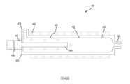
第4圖示出了根據本技術的一些實施例的示例性漿料遞送組件400的示意性橫截面圖。第4圖可示出關於組件200或300中的部件的進一步細節,諸如針對解塊管220或305。將理解,在一些實施例中,組件400包括先前論述的組件200或200的任何特徵或態樣。組件400可用於將研磨拋光漿料遞送到拋光墊,諸如本文描述的拋光墊110及205。組件400可圖示所論述並且可在類似於拋光系統100及/或組件200及300的拋光系統中整合的部件的部分視圖。組件400可包括解塊管405,該解塊管可與漿料流體源(未圖示)流體耦接。解塊管405可包括管主體410,該管主體具有入口415、出口420、及在入口415與出口420之間設置的中間區域425。在一些實施例中,中間區域425可具有與入口415及/或出口420相比較大的直徑。在一些實施例中,入口415及/或出口420可沿著中間區域425的中心軸定位。在其他實施例中,入口415及出口420中的一者或兩者可相對於中間區域425的中心軸偏移及/或成角度。例如,如所示出,入口415可大體上相對於中間區域425的中心軸正交(或處於另一角度)。入口415可在中間區域425的與出口420相對的端部處或靠近該端部定位。儘管本文圖示為入口415在中間區域425的頂部處形成,在各個實施例中,入口415可在中間區域425的底表面及/或側面上形成。在一些實施例中,中間區域425靠近出口420的端部可通常係漏斗形的及/或以其他方式漸縮以防止任何拋光漿料在解塊管405的拐角內堆積及/或以其他方式聚集。類似地,其他內部拐角可係圓的,其可有助於使得拋光漿料能夠穿過解塊管405一致地流動。Figure 4 shows a schematic cross-sectional view of an exemplary
組件400可包括與解塊管405耦接的數個超聲波換能器430。例如,一或多個超聲波換能器430可在波傳輸桿445上安裝及/或以其他方式與該波傳輸桿耦接。波傳輸桿445可具有近端,該近端在解塊管405的外側上與超聲波換能器430耦接。波傳輸桿445的遠端449可突出到解塊管405的中間區域425的內部。此可使得由超聲波換能器430產生的超聲波能夠經由波傳輸桿445穿過中間區域425的內部傳播,以有助於破碎可能已經在研磨漿料內形成的大粒子。波可從波傳輸桿445在相對於波傳輸桿445的縱軸橫向或以其他方式成角度及/或大體上沿著中間區域325的長度穿過波傳輸桿445的遠端449的方向上向外傳播。波傳輸桿445可沿著中間區域425的長度的至少或約5%、中間區域425的長度的至少或約10%、中間區域425的長度的至少或約20%、中間區域425的長度的至少或約30%、中間區域425的長度的至少或約40%、中間區域425的長度的至少或約50%、中間區域425的長度的至少或約60%、中間區域425的長度的至少或約70%、中間區域425的長度的至少或約80%、中間區域425的長度的至少或約90%、或更多延伸。在一些實施例中,解塊管405的出口420可從波傳輸桿445偏移。此在波傳輸桿445沿著中間區域425的實質長度延伸的實施例中可係特別有用的,因為出口420的此種定位可為拋光漿料流動到出口420中提供額外的餘隙。波傳輸桿445可由石英、用非反應性材料塗佈的金屬、及/或其他抗化學腐蝕材料形成。
在一些實施例中,監控拋光漿料及/或解塊管405的溫度可能係有用的,以確保拋光漿料足夠熱以適當地可流動並且不會太熱而使得拋光漿料沸騰或變得不適宜用於拋光操作。組件400可包括一或多個溫度感測器450,諸如熱電偶,該等溫度感測器可用於監控解塊管405及/或拋光漿料的溫度。溫度感測器450可與解塊管405耦接,諸如與解塊管405的中間區域425耦接。在一些實施例中,溫度感測器450可抵靠解塊管405的外表面定位,而在其他實施例中,溫度感測器450的至少一部分可在解塊管405的內部設置,諸如在中間區域425內。例如,整個溫度感測器450可在解塊管405的內部定位及/或溫度感測器450的一部分可穿過解塊管405的所有或一部分厚度突出。此可使得溫度感測器450能夠與拋光漿料接觸以提供溫度的準確讀數。In some embodiments, it may be useful to monitor the temperature of the polishing slurry and/or
組件400可包括一或多個溫度控制機構455,該等溫度控制機構可用於將解塊管405及/或拋光漿料的溫度維持在期望的溫度範圍內。溫度控制機構455可包括加熱及/或冷卻裝置。加熱裝置可包括但不限於電加熱線圈、加熱流體通道、熱鼓風機、及/或其他加熱機構。冷卻裝置可包括冷卻劑通道、冷卻空氣扇、及/或其他冷卻機構。溫度控制機構455可抵靠及/或以其他方式靠近解塊管405定位。例如,加熱及/或冷卻線圈/通道可抵靠及/或在解塊管405的外表面的一或多個側面周圍定位。線圈/通道可在各個實施例中沿著解塊管405的全部或一部分長度延伸。在一些實施例中,線圈/通道可完全纏繞在解塊管405的周邊周圍。鼓風機/風扇可靠近解塊管405定位並且可經定向以將空氣導引到解塊管405上及/或周圍。在一些實施例中,一或多個溫度控制機構455可在解塊管405的內部定位。溫度控制機構455可結合溫度感測器450操作以將拋光漿料及/或解塊管405維持在預定義的溫度範圍內,諸如在5℃及50℃之間或約5℃及50℃、在10℃及45℃之間或約10℃及45℃、在15℃及40℃之間或約15℃及40℃、在20℃及35℃之間或約20℃及35℃、或在25℃及30℃之間或約25℃及30℃。例如,若解塊管405及/或漿料的溫度下降到低於及/或接近下限閾值,則可致動(或調節)一或多個加熱裝置,而若溫度超過及/或接近上限溫度閾值,則可致動(或調節)一或多個冷卻裝置。此種操作可確保當拋光漿料從遞送噴口分配時拋光漿料適用於拋光操作。解塊管405的溫度可與拋光漿料的溫度相關聯,其可在一些實施例中使得拋光漿料的溫度能夠藉由取樣解塊管405的溫度來決定。
藉由靠近及/或在解塊管內定位超聲波換能器,本發明的實施例可將超聲波遞送到拋光漿料,該等超聲波在將拋光漿料遞送到拋光墊之前解塊及/或以其他方式破碎拋光漿料內的大粒子。實施例亦可包括確保將拋光漿料維持在期望的操作參數內的溫度控制反饋迴路。遞送可接受的拋光漿料可使得拋光操作能夠以較佳結果執行,並且幾乎不刮擦膜。By positioning the ultrasonic transducer close to and/or within the deblocking tube, embodiments of the present invention can deliver ultrasonic waves to the polishing slurry that deblock and/or deblock before delivering the polishing slurry to the polishing pad. Other methods break up large particles in the polishing slurry. Embodiments may also include a temperature control feedback loop to ensure that the polishing slurry is maintained within desired operating parameters. Delivering an acceptable polishing slurry can enable polishing operations to be performed with good results and little scratching of the film.
第5圖圖示了根據本技術的一些實施例的用於拋光基板的方法500中的示例性操作。方法500可使用漿料遞送組件執行,諸如本文描述的漿料遞送組件200、300、或400。方法500可在一些實施例中包括在基板拋光之前的操作。例如,在拋光之前,基板可具有所執行的一或多個沉積及/或蝕刻操作以及所執行的任何平坦化或其他製程操作。方法500可包括可在系統內自動執行的數個操作以限制人工相互作用,並且提供優於人工操作的增加的效率及精確度。方法500可結合習知CMP拋光製程執行。FIG. 5 illustrates exemplary operations in a
方法500可包括於操作505使拋光漿料流動到解塊管中。拋光漿料可包括分散在化學反應性溶液中的奈米大小的研磨粉末,其可有助於拋光及/或平坦化基板膜表面。於操作510,在拋光漿料穿過解塊管流動時可致動與解塊管耦接的一或多個超聲波換能器。例如,電流可供應到超聲波換能器,超聲波換能器可將該電流轉化為聲波。此等聲波可藉由超聲波換能器發射並且朝向解塊管導引,其中聲波可振動並且破碎已經在拋光漿料內形成的任何大粒子。有時,聲波可在約10 kHz與20 MHz之間,儘管其他頻率可在各個實施例中利用。於操作515,拋光漿料可遞送到拋光墊。例如,拋光漿料可穿過解塊管的出口並且穿過遞送噴口流動,該遞送噴口排出拋光墊的頂表面上的拋光漿料。拋光漿料可在拋光操作期間連續及/或週期性地遞送到拋光墊。
於操作520,可拋光拋光墊頂上的基板。例如,基板可在載具上面(膜側)朝下定位,此可旋轉及/或橫向平移基板抵靠拋光墊的面。漿料的化學溶液可化學蝕刻及軟化膜,而研磨粒子機械研磨及/或以其他方式移除膜的一部分以平坦化及/或以其他方式更改基板的表面。At
在一些實施例中,方法500可包括監控拋光漿料及/或解塊管的溫度。溫度可使用一或多個溫度感測器監控,諸如熱電偶,該等溫度感測器可抵靠、靠近、及/或在解塊管內定位。一或多個溫度控制機構(諸如加熱及/或冷卻裝置)可單獨或與溫度感測器結合操作以維持解塊管及/或拋光漿料的期望溫度。例如,當解塊管及/或拋光漿料的溫度低於及/或接近下限閾值時,可加熱解塊管及/或拋光漿料。當解塊管及/或拋光漿料的溫度高於及/或接近上限閾值時,可冷卻解塊管及/或拋光漿料。此可確保在遞送到拋光墊之前將拋光漿料維持在最佳溫度下並且可導致更有效的拋光操作。In some embodiments,
在前述描述中,出於解釋的目的,已經闡述數個細節以便提供對本技術的各個實施例的理解。然而,熟習此項技術者將顯而易見,可在沒有此等細節中的一些細節的情況下或具有額外細節的情況下實踐某些實施例。In the foregoing description, for purposes of explanation, several details have been set forth in order to provide an understanding of various embodiments of the present technology. It will be apparent, however, to one skilled in the art that certain embodiments may be practiced without some of these details or with additional details.
在已揭示若干實施例的情況下,熟習此項技術者將認識到可使用各種修改、替代配置、及等效者而不脫離實施例的精神。此外,尚未描述多種熟知製程及元素,以便避免不必要地混淆本技術。由此,以上描述不應當被認為限制技術的範疇。Having disclosed several embodiments, those skilled in the art will recognize that various modifications, alternative configurations, and equivalents may be used without departing from the spirit of the embodiments. Additionally, various well-known processes and elements have not been described in order to avoid unnecessarily obscuring the technology. Accordingly, the above description should not be considered as limiting the scope of the technology.
在提供值範圍的情況下,將理解除非上下文另外明確指出,亦具體地揭示每個中介值到在彼範圍的上限與下限之間的下限單位的最小分數。涵蓋在任何提及值或在所提及範圍中未提及的中介值與在所提及範圍中的任何其他提及值或中介值之間的任何較窄範圍。彼等較小範圍的上限及下限可獨立地包括或排除在範圍中,並且每個範圍(其中任一限值、無一限值、或兩個限值包括在較小範圍中)亦在技術內涵蓋,屬於在所提及範圍中任何具體排除的限值。在所提及範圍包括一或兩個限值的情況下,排除彼等包括的限值的任一個或兩個的範圍亦包括在內。Where a range of values is provided, it is understood that each intervening value, to the smallest fraction of the lower unit between the upper and lower limits of that range, is also specifically disclosed unless the context clearly dictates otherwise. Any narrower range between any stated value or intervening value not stated in a stated range and any other stated or intervening value in a stated range is encompassed. The upper and lower limits of those smaller ranges may independently be included or excluded in the range, and each range (where either limit, neither limit, or both limits are included in the smaller range) is also included in the technical covered within, falls within any specifically excluded limit in the range mentioned. Where the stated range includes one or both of the limits, ranges excluding either or both of those included limits are also included.
如在本文及隨附申請專利範圍中使用,除非上下文另外明確指出,否則單數形式「一(a)」、「一(an)」、及「該(the)」包括複數參考。因此,例如,提及「一加熱器」包括複數個此種加熱器,並且提及「該突出部」包括提及一或多突出部及熟習此項技術者已知的其等效物等等。As used herein and in the appended claims, the singular forms "a", "an", and "the" include plural references unless the context clearly dictates otherwise. Thus, for example, reference to "a heater" includes a plurality of such heaters and reference to "the protrusion" includes reference to one or more protrusions and equivalents thereof known to those skilled in the art, etc. .
此外,當在此說明書及以下申請專利範圍中使用時,詞語「包含(comprise(s))」、「包含(comprising)」、「含有(contain(s))」、「含有(containing)」、「包括(include(s))」、及「包括(including)」意欲規定存在所提及的特徵、整數、部件、或操作,但該等詞語不排除存在或添加一或多個其他特徵、整數、部件、操作等或群組。In addition, when used in this specification and the claims below, the words "comprise(s)", "comprising", "contain(s)", "containing", "Include(s)" and "including" are intended to specify the presence of a referenced feature, integer, component, or operation, but such words do not preclude the presence or addition of one or more other features, integers , widget, action, etc. or group.
100:拋光系統 102:平台組件 104:下部平台 106:上部平台 108:基板載具 110:拋光墊 112:基板 118:流體遞送臂 120:墊調節組件 122:研磨調節碟 200:漿料遞送組件 205:拋光墊 210:漿料流體源 215:支撐臂 217:基底 219:上部 220:解塊管 225:流體遞送內腔 227:入口 229:出口 230:遞送噴口 300:漿料遞送組件 305:解塊管 305a:解塊管 305b:解塊管 310:管主體 315:入口 320:出口 325:中間區域 330:超聲波換能器 335:基底板 340:配接器 342:外表面 344:內表面 400:漿料遞送組件 405:解塊管 410:管主體 415:入口 420:出口 425:中間區域 430:超聲波換能器 445:波傳輸桿 449:遠端 450:溫度感測器 455:溫度控制機構 500:方法 505:操作 510:操作 515:操作 520:操作 A:軸 B:軸100: Polishing system 102:Platform components 104: Lower platform 106: Upper platform 108: Substrate carrier 110: polishing pad 112: Substrate 118: Fluid delivery arm 120: Pad adjustment assembly 122: Grinding adjustment disc 200: slurry delivery assembly 205: polishing pad 210: slurry fluid source 215: support arm 217: Base 219: upper part 220: Deblocking tube 225: Fluid delivery lumen 227: Entrance 229: Export 230: delivery spout 300: slurry delivery assembly 305:
對所揭示技術的性質及優點的進一步理解可藉由參考說明書的剩餘部分及圖式來實現。A further understanding of the nature and advantages of the disclosed technology may be achieved by reference to the remaining portions of the specification and drawings.
第1圖圖示了根據本技術的一些實施例的示例性拋光系統的示意性橫截面圖。Figure 1 illustrates a schematic cross-sectional view of an exemplary polishing system in accordance with some embodiments of the present technology.
第2圖圖示了根據本技術的一些實施例的示例性漿料遞送組件的示意性部分橫截面圖。Figure 2 illustrates a schematic partial cross-sectional view of an exemplary slurry delivery assembly according to some embodiments of the present technology.
第3圖圖示了根據本技術的一些實施例的示例性漿料遞送組件的示意性部分橫截面圖。Figure 3 illustrates a schematic partial cross-sectional view of an exemplary slurry delivery assembly according to some embodiments of the present technology.
第3A圖圖示了根據本技術的一些實施例的第3圖的漿料遞送組件的示意性部分橫截面圖。Figure 3A illustrates a schematic partial cross-sectional view of the slurry delivery assembly of Figure 3, according to some embodiments of the present technology.
第3B圖係根據本技術的一些實施例的第3圖的漿料遞送組件的示意性部分橫截面圖。Figure 3B is a schematic partial cross-sectional view of the slurry delivery assembly of Figure 3, according to some embodiments of the present technology.
第4圖圖示了根據本技術的一些實施例的示例性漿料遞送組件的示意性部分橫截面圖。Figure 4 illustrates a schematic partial cross-sectional view of an exemplary slurry delivery assembly according to some embodiments of the present technology.
第5圖係根據本技術的一些實施例的拋光基板的示例性方法的流程圖。Figure 5 is a flowchart of an exemplary method of polishing a substrate in accordance with some embodiments of the present technology.
作為示意圖包括若干圖式。將理解圖式係出於說明目的,並且除非特別聲明為按比例,否則不認為該等圖式係按比例的。此外,作為示意圖提供圖式以輔助理解,並且與現實表示相比可能不包括所有態樣或資訊,並且出於說明目的可包括誇示的材料。Several figures are included as illustrations. It is to be understood that the drawings are for illustrative purposes and are not considered to be to scale unless specifically stated to be to scale. In addition, the drawings are provided as schematic diagrams to aid in understanding and may not include all aspects or information as compared to actual representations, and exaggerated material may be included for illustrative purposes.
在附圖中,類似部件及/或特徵可具有相同的元件符號。另外,相同類型的各個部件可藉由元件符號之後跟有在類似部件之間進行區分的字母來進行區分。若在本說明書中僅使用第一元件符號,則本說明適用於具有相同第一元件符號的類似部件的任一個,而與字母無關。In the figures, similar components and/or features may have the same reference number. Additionally, various components of the same type can be distinguished by the reference symbol followed by a letter that distinguishes between similar components. If only the first element symbol is used in this specification, the description is applicable to any one of the similar components having the same first element symbol regardless of the letter.
國內寄存資訊(請依寄存機構、日期、號碼順序註記) 無 國外寄存資訊(請依寄存國家、機構、日期、號碼順序註記) 無Domestic deposit information (please note in order of depositor, date, and number) none Overseas storage information (please note in order of storage country, institution, date, and number) none
200:漿料遞送組件200: slurry delivery assembly
205:拋光墊205: polishing pad
210:漿料流體源210: slurry fluid source
215:支撐臂215: support arm
217:基底217: Base
219:上部219: upper part
220:解塊管220: Deblocking tube
225:流體遞送內腔225: Fluid delivery lumen
227:入口227: Entrance
229:出口229: Export
230:遞送噴口230: delivery spout
Claims (20)
Translated fromChineseApplications Claiming Priority (2)
| Application Number | Priority Date | Filing Date | Title |
|---|---|---|---|
| US17/405,898 | 2021-08-18 | ||
| US17/405,898US20230054165A1 (en) | 2021-08-18 | 2021-08-18 | Point-of-use ultrasonic homogenizer for cmp slurry agglomeration reduction |
Publications (2)
| Publication Number | Publication Date |
|---|---|
| TW202308793Atrue TW202308793A (en) | 2023-03-01 |
| TWI840885B TWI840885B (en) | 2024-05-01 |
Family
ID=85228670
Family Applications (1)
| Application Number | Title | Priority Date | Filing Date |
|---|---|---|---|
| TW111126788ATWI840885B (en) | 2021-08-18 | 2022-07-18 | Slurry delivery assembly and method for cmp slurry agglomeration reduction |
Country Status (6)
| Country | Link |
|---|---|
| US (1) | US20230054165A1 (en) |
| JP (1) | JP2024531239A (en) |
| KR (1) | KR20240039064A (en) |
| CN (1) | CN117836093A (en) |
| TW (1) | TWI840885B (en) |
| WO (1) | WO2023022818A1 (en) |
Cited By (1)
| Publication number | Priority date | Publication date | Assignee | Title |
|---|---|---|---|---|
| CN117711991A (en)* | 2024-02-05 | 2024-03-15 | 苏州智程半导体科技股份有限公司 | A kind of wafer tank cleaning equipment |
Family Cites Families (18)
| Publication number | Priority date | Publication date | Assignee | Title |
|---|---|---|---|---|
| US5123433A (en)* | 1989-05-24 | 1992-06-23 | Westinghouse Electric Corp. | Ultrasonic flow nozzle cleaning apparatus |
| JPH07164320A (en)* | 1993-12-15 | 1995-06-27 | Y A Shii Kk | Polishing solution feeding device |
| JPH11277434A (en)* | 1998-03-30 | 1999-10-12 | Speedfam Co Ltd | Slurry recycle system for cmp device and method therefor |
| US6024829A (en)* | 1998-05-21 | 2000-02-15 | Lucent Technologies Inc. | Method of reducing agglomerate particles in a polishing slurry |
| US6106374A (en)* | 1998-07-16 | 2000-08-22 | International Business Machines Corporation | Acoustically agitated delivery |
| JP2000198062A (en)* | 1998-11-04 | 2000-07-18 | Canon Inc | Polishing apparatus and polishing method |
| US6439977B1 (en)* | 1998-12-07 | 2002-08-27 | Chartered Semiconductor Manufacturing Ltd. | Rotational slurry distribution system for rotary CMP system |
| JP3426149B2 (en)* | 1998-12-25 | 2003-07-14 | 富士通株式会社 | Method and apparatus for recycling polishing waste liquid in semiconductor manufacturing |
| JP3179064B2 (en)* | 1999-01-18 | 2001-06-25 | 株式会社東京精密 | Slurry supply equipment |
| US6196900B1 (en)* | 1999-09-07 | 2001-03-06 | Vlsi Technology, Inc. | Ultrasonic transducer slurry dispenser |
| JP2004063858A (en)* | 2002-07-30 | 2004-02-26 | Renesas Technology Corp | Method for manufacturing semiconductor device |
| US6939210B2 (en)* | 2003-05-02 | 2005-09-06 | Applied Materials, Inc. | Slurry delivery arm |
| ES2708853T3 (en)* | 2007-06-25 | 2019-04-11 | Mondofix Inc | Device and method of removing scratches |
| JP5297695B2 (en)* | 2008-05-30 | 2013-09-25 | Sumco Techxiv株式会社 | Slurry supply device and semiconductor wafer polishing method using the same |
| KR101682515B1 (en)* | 2016-05-23 | 2016-12-12 | 곽은희 | In-line sonic slurry particle |
| CN210205982U (en)* | 2019-06-05 | 2020-03-31 | 德淮半导体有限公司 | Grinding fluid filtering device |
| CN112677032A (en)* | 2019-10-17 | 2021-04-20 | 夏泰鑫半导体(青岛)有限公司 | Grinding fluid conveying module and chemical mechanical grinding device |
| CN110681303A (en)* | 2019-11-27 | 2020-01-14 | 湖南大合新材料有限公司 | Polishing solution preparation device |
- 2021
- 2021-08-18USUS17/405,898patent/US20230054165A1/enactivePending
- 2022
- 2022-07-13JPJP2024508698Apatent/JP2024531239A/enactivePending
- 2022-07-13WOPCT/US2022/036960patent/WO2023022818A1/ennot_activeCeased
- 2022-07-13KRKR1020247008510Apatent/KR20240039064A/enactivePending
- 2022-07-13CNCN202280056327.3Apatent/CN117836093A/enactivePending
- 2022-07-18TWTW111126788Apatent/TWI840885B/enactive
Cited By (1)
| Publication number | Priority date | Publication date | Assignee | Title |
|---|---|---|---|---|
| CN117711991A (en)* | 2024-02-05 | 2024-03-15 | 苏州智程半导体科技股份有限公司 | A kind of wafer tank cleaning equipment |
Also Published As
| Publication number | Publication date |
|---|---|
| WO2023022818A1 (en) | 2023-02-23 |
| CN117836093A (en) | 2024-04-05 |
| KR20240039064A (en) | 2024-03-26 |
| JP2024531239A (en) | 2024-08-29 |
| TWI840885B (en) | 2024-05-01 |
| US20230054165A1 (en) | 2023-02-23 |
Similar Documents
| Publication | Publication Date | Title |
|---|---|---|
| CN111836700B (en) | Apparatus and method for CMP temperature control | |
| JP3550316B2 (en) | Method and system for removing agglomerated particles in a polishing slurry | |
| CN100469528C (en) | Vacuum assisted pad cleaning system and method employing perforated cleaning plate | |
| CN201244770Y (en) | Polishing pad regulator and chemical mechanical device equipped therewith | |
| US6508697B1 (en) | Polishing pad conditioning system | |
| TWI839317B (en) | Low-temperature metal cmp for minimizing dishing and corrosion, and improving pad asperity | |
| TW202506321A (en) | Slurry temperature control by mixing at dispensing | |
| TWI399805B (en) | A system and method for removing particles from a polishing pad | |
| US20140323017A1 (en) | Methods and apparatus using energized fluids to clean chemical mechanical planarization polishing pads | |
| JP2003229393A (en) | Combination of slurry dispenser and rinse arm, and operation method | |
| US20130072091A1 (en) | Method for the double-side polishing of a semiconductor wafer | |
| TWI879280B (en) | Apparatus and method for cmp temperature control | |
| TW202308793A (en) | Point-of-use ultrasonic homogenizer for cmp slurry agglomeration reduction | |
| TWI687992B (en) | Chemical mechanical polishing method and apparatus | |
| JP2000031100A (en) | Slurry supply system for semiconductor CMP process | |
| JP2008500198A (en) | Polishing pad with rocking path groove network | |
| TWI834221B (en) | Substrate edge polishing apparatus and method | |
| CN115996817A (en) | Hot water generation for chemical mechanical polishing |