TW202306373A - Image correction system and method thereof capable of recovering image records being horizontal, without truncation, and consistent with aspect ratio of original image - Google Patents
Image correction system and method thereof capable of recovering image records being horizontal, without truncation, and consistent with aspect ratio of original imageDownload PDFInfo
- Publication number
- TW202306373A TW202306373ATW110127931ATW110127931ATW202306373ATW 202306373 ATW202306373 ATW 202306373ATW 110127931 ATW110127931 ATW 110127931ATW 110127931 ATW110127931 ATW 110127931ATW 202306373 ATW202306373 ATW 202306373A
- Authority
- TW
- Taiwan
- Prior art keywords
- image
- original
- pixels
- total number
- pixel
- Prior art date
Links
Images


Landscapes
- Apparatus For Radiation Diagnosis (AREA)
- Closed-Circuit Television Systems (AREA)
- Image Processing (AREA)
Abstract
Description
Translated fromChinese本發明是有關一種影像校正系統及其方法,是一種能夠回歸為水平、未截角、且與原影像長寬比一致的影像紀錄之影像校正系統及其方法。The present invention relates to an image correction system and its method. It is an image correction system and its method that can return to an image record that is horizontal, untruncated, and consistent with the aspect ratio of the original image.
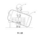
現今以手機顯示APP選單時,只能依手機的橫向(影像寬面在水平,窄面在垂直方向)或縱向(影像窄面在水平,寬面在垂直方向) ,依重力感測元件自動調整可視影像,以每90度「固定級距」方式顯示在屏幕,無法顯示任意角度;也無法調整出鏡頭與顯示屏幕角度在小角度(小於90度)的傾角差別,以第1A圖解釋,在拍攝時,被拍攝人1之實像與拍攝端設備11屏幕上的影像在拍攝時人像的身體角度與屏幕上的人像身體角度都是朝上,不會有角度上的偏差或小於90度旋轉,即使使用三軸平衡雲台亦是如此。Nowadays, when displaying the APP menu on a mobile phone, it can only be adjusted automatically according to the gravity sensing element according to the horizontal orientation of the mobile phone (the wide side of the image is horizontal, the narrow side is vertical) or the vertical direction (the narrow side of the image is horizontal, and the wide side is vertical). Visible images are displayed on the screen in the form of "fixed steps" every 90 degrees, which cannot be displayed at any angle; nor can the angle difference between the lens and the display screen be adjusted at small angles (less than 90 degrees), as explained in Figure 1A. When shooting, the body angle of the real image of the subject 1 and the image on the screen of the
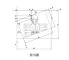
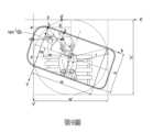
而透過有些技術,能夠控制旋轉圖像的角度,然後原影像旋轉回歸任一角度,若不改變影像大小則至少會有二個影像框角跑到影像框外而造成截角缺點,使影像不完整,以第1B圖所示,當將拍攝完的影像傳給另一個接收端顯示設備12後,接收端顯示設備12即使有功能旋轉回水平後影像,如第1B圖所示,其中原拍攝虛框線121部分為示意拍攝獲得的影像邊界,若以中心為旋轉,則四個角皆有截角失真之現象發生。And through some technologies, the angle of the rotated image can be controlled, and then the original image is rotated back to any angle. If the image size is not changed, at least two image frame corners will run outside the image frame, resulting in truncation defects, so that the image will not be correct. Complete, as shown in Figure 1B, when the captured image is transmitted to another
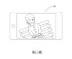
另外,更有一種問題,如第2A圖所示,就是當被拍攝者2使用拍攝端設備21拍攝之原影像之攝影鏡頭不在水平位置時,而當接收端或事後觀看錄像時,如第2B圖所示,其接收端顯示設備22上顯示之畫面,會讓觀看者混淆被拍實景與攝影鏡頭傾角之關係,無法弄清楚到底是左邊較高或右邊較高;In addition, there is another problem, as shown in Figure 2A, that is, when the
以習知專利來看,不論是ZL.201710967824.X的左右鏡射技術、JP U3111261的影像反轉技術、JP 2003-219224的手動翻轉鏡頭模塊的電子手持鏡專利,皆沒有考慮到拍攝端鏡頭對水平傾斜時的調整,而ZL.201710967824.X的左右鏡射專利也只處理了相機中內參數(Intrinsic)的座標轉換,但當使用者持攝影鏡頭在自然座標系統中使用時,多多少少會因手持鏡頭的方便持握性好或不好,在攝影鏡頭的拍攝軸方向會產生旋轉(相機外參數 Extrinsic 改變),接收的一方有影像水平歪斜的不適應(如前所述);From the perspective of conventional patents, whether it is ZL.201710967824.X’s left-right mirroring technology, JP U3111261’s image inversion technology, or JP 2003-219224’s electronic hand-held mirror patent for manually flipping the lens module, none of them take into account the shooting end lens For the adjustment of horizontal tilt, the left and right mirror patent of ZL.201710967824.X only deals with the coordinate conversion of the intrinsic parameters (Intrinsic) in the camera, but when the user holds the photographic lens and uses it in the natural coordinate system, how much more Rarely, due to the convenience of hand-held lens, whether the grip is good or not, the shooting axis direction of the photographic lens will rotate (the extrinsic parameter of the camera changes), and the receiving party will not adapt to the horizontal distortion of the image (as mentioned above);
然現今具有攝影鏡頭的手機多具備重力感測器(或稱「重力線角度測量元件」),部分已具有防手震(Anti-Shake)動態修正技術,但仍無法達到影像任意傾角回歸水平並保持長寬比例技術之目的,甚為可惜。However, most mobile phones with camera lenses today have gravity sensors (or "gravity line angle measurement components"), and some have anti-shake dynamic correction technology, but they still cannot achieve the level of image regression at any inclination angle and It is a pity to maintain the purpose of aspect ratio technology.
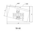
如前所述,目前市面上有使用三軸穩定器(三軸平衡雲台),如第3圖所示,這一類的三軸穩定器3確實能夠及時調整使拍攝之影像都能夠保持水平的狀態,因此不論使用者如何晃動或移動,都能夠保持影像的穩定度,然而這一類的設備,若是要足夠精準與速度要快,其設備必然很重且組件很多,故對於一般使用者來講攜帶外出是尤其負擔且不方便的。As mentioned earlier, there are currently three-axis stabilizers (three-axis balanced gimbals) on the market. As shown in Figure 3, this type of three-axis stabilizer 3 can indeed be adjusted in time to keep the captured images level. state, so no matter how the user shakes or moves, it can maintain the stability of the image. However, if this type of equipment is to be accurate enough and fast enough, the equipment must be heavy and have many components, so for ordinary users It is particularly burdensome and inconvenient to carry out.
因此,為了能夠依持續變動的影像任意傾角持續校正回歸水平影像,且能夠回歸為未截角、且與原影像長寬比一致的影像紀錄,本案提出一種影像回歸應用單元,該影像回歸應用單元係至少包含有一傾角校正元件及一長寬校正元件,其中該影像回歸應用單元用以於一或多個影像資訊檔取出一原始拍攝影像及一傾斜角度資訊,並再依據該傾斜角度資訊輸出新的像素位置,並再進行校正影像長寬比例,用以取得攝像裝置傾斜時最小完整影像水平傾角回歸並保持長寬比例的結果,以能夠回歸為水平、未截角、且與原影像長寬比一致的影像紀錄,因此本發明應為一最佳解決方案。Therefore, in order to continuously correct and regress the horizontal image according to the arbitrary inclination of the continuously changing image, and to return to an image record with no truncated angle and the same aspect ratio as the original image, this project proposes an image regression application unit, the image regression application unit It comprises at least one inclination correction element and one aspect correction element, wherein the image regression application unit is used to extract an original shot image and an inclination angle information from one or more image information files, and then output a new one based on the inclination angle information The pixel position, and then correct the aspect ratio of the image to obtain the minimum complete image horizontal inclination angle regression and maintain the aspect ratio when the camera device is tilted, so that it can return to the horizontal, untruncated angle, and the original image length and width Consistent image recording, so the present invention should be an optimal solution.
本發明影像校正系統,係設置於電子設備上,該電子設備有至少一個處理器及至少一個電腦可讀取記錄之媒體,而該電子設備能夠輸出影像至一顯示螢幕上,且該電腦可讀取記錄之媒體儲存有一或多個影像資訊檔,其中該影像校正系統及其方法係包含有:至少一個影像回歸應用單元,係儲存於該電腦可讀取記錄之媒體內,而該影像回歸應用單元係包含有:一傾角校正元件,係能夠於一或多個影像資訊檔取出一原始拍攝影像及一傾斜角度資訊,並於掃描該原始拍攝影像之每幀影像訊號,以取得一原始水平方向像素總數(w)、一原始垂直方向像素總數(h)、一任一原始像素水平座標(x)及一任一原始像素垂直座標(y),之後依據該原始水平方向像素總數(w)及該原始垂直方向像素總數(h)圍繞該原始拍攝影像輸出一第一水平方向像素總數(w’)及一第一垂直方向像素總數(h’)並產生出一圍繞框,該圍繞框係與該原始拍攝影像之影像邊界的四頂點相接觸,並依據該傾斜角度資訊輸出一未傾斜狀態下之第一像素水平座標(x’)及第一像素垂直座標(y’),以使該原始拍攝影像能夠依據多個第一像素水平座標(x’)及多個第一像素垂直座標(y’)產生出新的像素位置,以依據新的像素位置將該原始拍攝影像校正回不具傾角的水平狀態;以及一長寬校正元件,係與該傾角校正元件相連接,能夠依據該原始影像等長寬比(h/w)取得一第二水平方向像素總數(w’’)及一第二垂直方向像素總數(h’’),並依據該第二水平方向像素總數(w’’)、該第一水平方向像素總數(w’)及該第一像素水平座標(x’)輸出一第二像素水平座標(x’’),並依據該第一像素垂直座標(y’)輸出一第二像素垂直座標(y’’),用以校正輸出至該顯示螢幕上的影像能夠與該原始拍攝影像之影像長寬比例一致。The image correction system of the present invention is set on an electronic device, the electronic device has at least one processor and at least one computer-readable recording medium, and the electronic device can output an image to a display screen, and the computer-readable The recording medium stores one or more image information files, wherein the image correction system and method thereof include: at least one image regression application unit, which is stored in the computer-readable recording medium, and the image regression application The unit includes: an inclination correction element, which can extract an original shot image and a tilt angle information from one or more image information files, and scan each frame of the original shot image to obtain an original horizontal direction The total number of pixels (w), the total number of pixels in the original vertical direction (h), the horizontal coordinate (x) of any original pixel, and the vertical coordinate (y) of any original pixel, and then according to the total number of pixels in the original horizontal direction (w) and the original The total number of pixels in the vertical direction (h) surrounds the original shot image to output a first total number of pixels in the horizontal direction (w') and a first total number of pixels in the vertical direction (h') and generate a surrounding frame, which is the same as the original The four vertices of the image boundary of the captured image are in contact, and output a first pixel horizontal coordinate (x') and a first pixel vertical coordinate (y') in an untilted state according to the tilt angle information, so that the original captured image A new pixel position can be generated according to a plurality of first pixel horizontal coordinates (x') and a plurality of first pixel vertical coordinates (y'), so that the original shot image can be corrected back to a horizontal state without inclination according to the new pixel position ; and an aspect correction element, which is connected with the tilt correction element, and can obtain a second total number of pixels in the horizontal direction (w'') and a second vertical direction according to the equal aspect ratio (h/w) of the original image The total number of pixels (h''), and output a second pixel according to the second total number of horizontal pixels (w''), the first total number of horizontal pixels (w') and the first pixel horizontal coordinate (x') Horizontal coordinate (x''), and output a second pixel vertical coordinate (y'') according to the first pixel vertical coordinate (y'), which is used to correct the image output to the display screen to be consistent with the original captured image The aspect ratio of the image is the same.
更具體的說,所述圍繞框係為一外接矩形框,其中該外接矩形框係沿著該原始拍攝影像之影像邊界的四頂點所形成。More specifically, the surrounding frame is a circumscribing rectangular frame, wherein the circumscribing rectangular frame is formed along four vertices of the image boundary of the original captured image.
更具體的說,所述圍繞框係為一圓框,其中該圓框係以該原始拍攝影像的中心為圓心所形成,而該原始拍攝影像之影像邊界的四頂點係接觸於該圓框上。More specifically, the surrounding frame is a circular frame, wherein the circular frame is formed with the center of the original captured image as the center, and the four vertices of the image boundary of the original captured image are in contact with the circular frame.
更具體的說,所述電子設備能夠設置或連接有一與該處理器電性連接之攝影鏡頭及一與該處理器電性連接之重力角度感測器,並能夠透過該攝影鏡頭拍攝產生該原始拍攝影像以及透過該重力角度感測器偵測到該傾斜角度資訊。More specifically, the electronic device can be provided or connected with a photographic lens electrically connected to the processor and a gravity angle sensor electrically connected to the processor, and can generate the original image through the photographic lens. Shooting images and detecting the tilt angle information through the gravity angle sensor.
更具體的說,所述影像資訊檔係為一每幀影像含有該傾斜角度資訊(重力線角度資訊θ)的原始拍攝影像。More specifically, the image information file is an original captured image containing the inclination angle information (gravity line angle information θ) in each frame of image.
更具體的說,所述每幀影像含有該傾斜角度資訊(重力線角度資訊θ)的原始拍攝影像係為一可交換影像檔案格式 (例如:日本標準為Exchangeable image file format,Exif) 。More specifically, the original captured image containing the inclination angle information (gravity line angle information θ) for each frame of image is in an exchangeable image file format (for example: the Japanese standard is Exchangeable image file format, Exif).
更具體的說,所述影像回歸應用單元係具有一控制開關元件,用以控制於該顯示螢幕上顯示之影像係為校正後之原始拍攝影像或是未校正之原始拍攝影像。More specifically, the image regression application unit has a control switch element for controlling whether the image displayed on the display screen is a corrected original captured image or an uncorrected original captured image.
更具體的說,所述顯示螢幕能夠設置於該電子設備上或是透過一連接件或是無線連接方式與該電子設備連接。More specifically, the display screen can be set on the electronic device or connected with the electronic device through a connector or wireless connection.
一種影像校正方法,其步驟為: (1) 一影像回歸應用單元於一或多個影像資訊檔取出一原始拍攝影像及一傾斜角度資訊,並於掃描該原始拍攝影像之每幀影像訊號,以取得一原始水平方向像素總數(w)、一原始垂直方向像素總數(h)、一任一原始像素水平座標(x)及一任一原始像素垂直座標(y); (2) 該影像回歸應用單元依據該原始水平方向像素總數(w)及該原始垂直方向像素總數(h)圍繞該原始拍攝影像輸出一第一水平方向像素總數(w’)及一第一垂直方向像素總數(h’)並產生出一圍繞框,該圍繞框係與該原始拍攝影像之影像邊界的四頂點相接觸; (3) 該影像回歸應用單元依據該傾斜角度資訊輸出一未傾斜狀態下之第一像素水平座標(x’)及第一像素垂直座標(y’),以使該原始拍攝影像能夠依據多個第一像素水平座標(x’)及多個第一像素垂直座標(y’)產生出新的像素位置,以依據新的像素位置將該原始拍攝影像校正回不具傾角的水平狀態;以及 (4) 該影像回歸應用單元依據一用以輸出影像之原始影像等長寬比(h/w)取得一第二水平方向像素總數(w’’)及一第二垂直方向像素總數(h’’),並依據該第二水平方向像素總數(w’’)、該第一水平方向像素總數(w’)及該第一像素水平座標(x’)輸出一第二像素水平座標(x’’),並再依據該第一像素垂直座標(y’)輸出一第二像素垂直座標(y’’),用以校正輸出至該顯示螢幕上的影像能夠與該原始拍攝影像之影像長寬比例一致。An image correction method, the steps of which are: (1) An image regression application unit extracts an original shot image and a tilt angle information from one or more image information files, and scans the image signal of each frame of the original shot image to obtain a total number of pixels in the original horizontal direction (w ), a total number of pixels in the original vertical direction (h), a horizontal coordinate (x) of any original pixel and a vertical coordinate (y) of any original pixel; (2) The image regression application unit outputs a first total number of pixels in the horizontal direction (w') and a first total number of pixels in the vertical direction around the original captured image according to the total number of pixels in the original horizontal direction (w) and the total number of pixels in the original vertical direction (h). The total number of direction pixels (h') and generate a surrounding frame, which is in contact with the four vertices of the image boundary of the original captured image; (3) The image regression application unit outputs a horizontal coordinate (x') and a vertical coordinate (y') of the first pixel in a non-tilted state according to the tilt angle information, so that the original shot image can be based on multiple The first pixel horizontal coordinate (x') and the plurality of first pixel vertical coordinates (y') generate a new pixel position, so as to correct the original shot image back to a horizontal state without tilt angle according to the new pixel position; and (4) The image regression application unit obtains a second total number of pixels in the horizontal direction (w'') and a second total number of pixels in the vertical direction (h') according to an aspect ratio (h/w) of the original image used to output the image '), and output a second pixel horizontal coordinate (x') according to the second total number of pixels in the horizontal direction (w''), the first total number of pixels in the horizontal direction (w') and the first pixel horizontal coordinate (x') '), and then output a second pixel vertical coordinate (y'') based on the first pixel vertical coordinate (y'), which is used to correct the image output to the display screen and the image length and width of the original captured image The ratio is consistent.
有關於本發明其他技術內容、特點與功效,在以下配合參考圖式之較佳實施例的詳細說明中,將可清楚的呈現。Other technical contents, features and effects of the present invention will be clearly presented in the following detailed description of preferred embodiments with reference to the drawings.
請參閱第4A及4B圖,為本發明影像校正系統及其方法之整體架構示意圖及影像回歸應用單元之架構示意圖,由圖中可知,該影像校正系統係設置於一電子設備4(電子設備4能夠為手持智慧型裝置、平板電腦、攝像機、錄像機或是筆記型電腦等有鏡頭的設備)上,該電子設備4有至少一個處理器41及至少一個電腦可讀取記錄之媒體42,而該電子設備4能夠輸出影像至一顯示螢幕43上,而該顯示螢幕43能夠設置於該電子設備4上(或是如第5圖所示,該顯示螢幕6透過一連接件或是無線連接方式與該電子設備5連接用以進行顯示);Please refer to Figures 4A and 4B, which are a schematic diagram of the overall architecture of the image correction system and its method of the present invention and a schematic diagram of the architecture of the image regression application unit. It can be seen from the figures that the image correction system is set on an electronic device 4 (
而該電腦可讀取記錄之媒體42儲存有一或多個影像資訊檔(動態影像或是靜態影像)及至少一個影像回歸應用單元421,而該影像回歸應用單元421之架構與資訊處理,如第4B圖所示,係包含有: (1) 一傾角校正元件4212,係能夠透過一影像輸入元件4211於該電腦可讀取記錄之媒體42內取出影像資訊檔(或是透過影像輸入元件4211由外部設備中取得影像資訊檔),並於一或多個影像資訊檔取出一原始拍攝影像及一傾斜角度資訊(是指攝影鏡頭的傾斜角度,一般是透過重力角度感測器進行感測所取得,故也能稱為重力線角度資訊θ),並於掃描該原始拍攝影像之每幀影像訊號,以取得一原始水平方向像素總數(w)、一原始垂直方向像素總數(h)、一任一原始像素水平座標(x)及一任一原始像素垂直座標(y),之後依據該原始水平方向像素總數(w)及該原始垂直方向像素總數(h)圍繞該原始拍攝影像輸出一第一水平方向像素總數(w’)及一第一垂直方向像素總數(h’)並產生出一圍繞框,該圍繞框係與該原始拍攝影像之影像邊界的四頂點相接觸,並依據該傾斜角度資訊輸出一未傾斜狀態下之第一像素水平座標(x’)及第一像素垂直座標(y’),以使該原始拍攝影像能夠依據多個第一像素水平座標(x’)及多個第一像素垂直座標(y’)產生出新的所有像素位置,以依據新的像素位置將該原始拍攝影像校正回不具傾角的水平狀態; (2) 一長寬校正元件4213,係與該傾角校正元件4212相連接,能夠依據原始影像等長寬比(h/w)取得一第二水平方向像素總數(w’’)及一第二垂直方向像素總數(h’’),並依據該第二水平方向像素總數(w’’)、該第一水平方向像素總數(w’)及該第一像素水平座標(x’)輸出一第二像素水平座標(x’’),並依據該第一像素垂直座標(y’)輸出一第二像素垂直座標(y’’),用以校正輸出至該顯示螢幕43上的影像能夠與該原始拍攝影像之影像長寬比例一致(即:w”/h” = w/h,下同); (3) 一控制開關元件4214,係與該長寬校正元件4213相連接,用以控制於該顯示螢幕43上顯示之影像係為校正後之原始拍攝影像或是未校正之原始拍攝影像,而該長寬校正元件4213能夠將該原始水平方向像素總數(w)、原始垂直方向像素總數(h)、任一原始像素水平座標(x)、任一原始像素垂直座標(y) 、第二水平方向像素總數(w’’) 、第二垂直方向像素總數(h’’) 、任一第二像素水平座標(x’’) 、任一第二像素垂直座標(y’’)傳送給該控制開關元件4214,如第6圖所示,若是關閉該控制開關元件4214,則將原始水平方向像素總數(w)、原始垂直方向像素總數(h)、任一原始像素水平座標(x)、任一原始像素垂直座標(y) 透過該影像輸出元件4215輸出未校正之原始拍攝影像於該顯示螢幕43上;反之,若是開啟該控制開關元件4214,則將第二水平方向像素總數(w’’) 、第二垂直方向像素總數(h’’) 、任一第二像素水平座標(x’’) 、任一第二像素垂直座標(y’’) 透過該影像輸出元件4215輸出校正後之原始拍攝影像於該顯示螢幕43上。And the computer-
另外,本案之傾角校正元件4212、長寬校正元件4213及控制開關元件4214除了能夠以軟體方式搭配軟體介面進行控制之外,亦能夠透過電子設備4設置或外接有一實體操控面板,能夠透過實體操控面板上的不同實體按鍵或相關元件,來啟動或關閉該傾角校正元件4212、長寬校正元件4213及控制開關元件4214之運作。In addition, the
如第4A圖所示,該電子設備4更能夠設置或連接有一與該處理器41電性連接之攝影鏡頭44及一與該處理器41電性連接之重力角度感測器45,並能夠透過該攝影鏡頭44拍攝產生該原始拍攝影像以及透過該重力角度感測器45偵測到該傾斜角度資訊;另外亦能夠如第5圖所示,該電子設備5本身能夠不需設置攝影鏡頭及重力角度感測器,能夠透過一連接件或是無線連接方式,來連接取得外部設備7所提供的影像資訊檔。As shown in Figure 4A, the
而影像資訊檔能夠包含有原始拍攝影像及傾斜角度資訊,其中影像資訊檔來源為: (1) 若分析裝置本身具有攝影鏡頭及重力角度感測器,則能夠由攝影鏡頭拍攝產生該原始拍攝影像,並由重力角度感測器偵測到該傾斜角度資訊; (2) 若分析裝置本身具有攝影鏡頭及重力角度感測器,能夠由一外部設備傳送一每幀影像含有該傾斜角度資訊(重力線角度資訊θ)的原始拍攝影像,這一類的原始拍攝影像係為一可交換影像檔案格式 (例如日本標準:Exchangeable image file format,Exif); (3) 若分析裝置本身不具有攝影鏡頭或/及重力角度感測器,能夠由一外部設備傳送一每幀影像含有該傾斜角度資訊(重力線角度資訊θ)的原始拍攝影像,這一類的原始拍攝影像係為一可交換影像檔案格式 (例如日本標準:Exchangeable image file format,Exif)。The image information file can contain the original shooting image and tilt angle information, and the source of the image information file is: (1) If the analysis device itself has a photographic lens and a gravity angle sensor, the original captured image can be captured by the photographic lens, and the tilt angle information can be detected by the gravity angle sensor; (2) If the analysis device itself has a camera lens and a gravity angle sensor, an external device can transmit an original shot image containing the tilt angle information (gravity line angle information θ) for each frame of image. This type of original shot image It is an exchangeable image file format (such as Japanese standard: Exchangeable image file format, Exif); (3) If the analysis device itself does not have a photographic lens or/and a gravity angle sensor, an external device can transmit an original shot image containing the inclination angle information (gravity line angle information θ) for each frame of image, this type of The original captured image is in an exchangeable image file format (eg Japanese standard: Exchangeable image file format, Exif).
而本案前述之圍繞框係為一外接矩形框,也就是外接新座標軸(取得最適影像),其中該外接矩形框係沿著該原始拍攝影像之影像邊界的四頂點所形成,以第7A及7B圖進一步說明,若原影像寬度為w像素,高度為h像素,則「外接新座標軸影像」仍以左上角為影像處理原點時,將不會有截角產生,但是會因為傾角為正(順時針轉)、為負(逆時針轉)會產生2組新座標,而傾角校正元件4212之運算說明如下(本專利以目前影像處理大多採用之左上角為原點,揭示公式推導,一般此領域技術人員可以依以下之步驟,另行轉換以左下角、右上角、右下角為原點之公式): (1) 如第7A圖所示,當原攝影鏡頭為順時針傾斜正角,也就是傾斜角度資訊(重力線角度資訊θ)大於等於0且小於90度時,先由原始拍攝影像取得原始水平方向像素總數(w)、原始垂直方向像素總數(h)、任一原始像素水平座標(x)及任一原始像素垂直座標(y),而運算方式如下: (a) 第一水平方向像素總數(w’)運算方式如下:


而以不同角度呈現以下不同實施樣態: (1) 如第8A圖,是代表原攝影鏡頭為順時針傾斜正角(正15度),其中影像邊界42121的框線是代表原始拍攝影像之影像邊界,而框線42122的框線是代表外接矩形框; (2) 如第8B圖,是代表原攝影鏡頭為逆時針傾斜負角(負45度),其中影像邊界42121的框線是代表原始拍攝影像之影像邊界,而框線42122的框線是代表外接矩形框。The following different implementation states are presented from different angles: (1) As shown in Figure 8A, it represents that the original photographic lens is tilted clockwise at a positive angle (positive 15 degrees), where the frame line of the
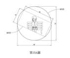
而本案前述之圍繞框係為一圓框,也就是以原影像中心為圓心,影像四頂點外接圓(中心旋轉影像),而該原始拍攝影像之影像邊界的四頂點係接觸於該圓框上,以第9圖進一步說明,當以原影像中心為圓心,影像四頂點外接圓 (中心旋轉影像),以第9圖為例,若原影像寬度仍為w像素,高度仍為h像素,則以影像四頂點外接圓的水平向右上切線、垂直向下左切線為新座標軸,「外接圓所切新座標軸影像」原為影像左上角為影像處理原點,改為新座標時,因為都在正象限,不會有截角產生,只會產生1組新座標,而傾角校正元件4212之運算說明如下: (1) 第一水平方向像素總數(w’)運算方式如下:


而以不同角度呈現以下不同實施樣態: (1) 如第10A圖,是代表原攝影鏡頭為順時針傾斜正角(正15度),其中影像邊界42121的框線是代表原始拍攝影像之影像邊界,而框線42123是代表圓框; (2) 如第10B圖,是代表原攝影鏡頭為逆時針傾斜負角(負45度),其中影像邊界42121的框線是代表原始拍攝影像之影像邊界,而框線42123是代表圓框。The following different implementation states are presented from different angles: (1) As shown in Figure 10A, it represents that the original photographic lens is tilted clockwise at a positive angle (positive 15 degrees), where the frame line of the
而以前述第8A圖為例,原寬、長比(w , h)為2:1的虛線影像,若完成傾角校正後,(w’ , h’)仍以寬、長比例2:1轉出會變成如第11圖的樣態,由圖中可知,影像(框線42125示意為校正後失真影像範圍)已扭曲失真,必須加以處理。Taking the aforementioned Figure 8A as an example, the dotted line image whose original width to length ratio (w , h) is 2:1, after the tilt correction is completed, (w' , h') will still be transformed with a width to length ratio of 2:1 It will appear as shown in Figure 11. It can be seen from the figure that the image (the
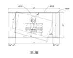
如第12圖所示,w’、h’標示範例之圍繞框為原影像之影像邊界42121之外接矩形框42122,並以框線42124示意為長寬比校正後影像範圍,並使原影像之影像邊界42121居中,並以w大於等於h為說明(w小於h依下式一般技術人員皆可推導,故不額外贅述),而長寬比校正說明如下: (1) 若要保持為影像長寬比例,則公式6如下:


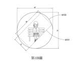
如第13圖所示,圍繞框為圓框42123,並以框線42124示意為校正後影像範圍,並使原影像之影像邊界42121居中,另以圓框為示意原影像之影像邊界42121之外接圓,找出X’方向偏置量,而長寬比校正說明如下: (1) 若要保持為影像長寬比例,則公式7如下:


另外,由於一般顯示器都自帶Auto Fit能力,所以手機投影給手機或手機投影給電視,都能自動擴延至顯示器最大可顯示狀態,故本案使用原始影像等長寬比(h/w)進行校正,故本案之長寬比校正不須理會任何顯示螢幕之規格(例如:長、寬各多少像素)。In addition, since the general display has its own Auto Fit capability, the projection of the mobile phone to the mobile phone or the mobile phone to the TV can be automatically extended to the maximum displayable state of the display, so this case uses the original image to correct the aspect ratio (h/w) , so the aspect ratio correction in this case does not need to care about the specifications of any display screen (for example: the number of pixels in length and width).
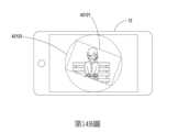
另外,針對第1A圖進行校正後,若是透過外接新座標軸(以圍繞框為外接矩形框)的方法進行校正,其效果如第14A圖所示;若是以中心旋轉影像的外接圓新座標軸的方法進行校正,其效果如第14B圖所示,其中影像邊界42121為示意影像邊界、框線42122為示意影像外接矩形、框線42123為示意影像外接圓,其效果明顯能改善其問題。In addition, after correcting Figure 1A, if it is corrected by circumscribed new coordinate axes (with the surrounding frame as a circumscribed rectangular frame), the effect is shown in Figure 14A; Correction is performed, and the effect is shown in FIG. 14B, where the
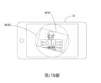
另外,針對第2B圖進行校正後,若是透過外接新座標(以圍繞框為外接矩形框)的方法進行校正,其效果如第15A圖所示;若是以中心旋轉影像的外接圓方法進行校正,其效果如第15B圖所示,其中影像邊界42121為示意影像邊界、框線42122為示意影像外接矩形、框線42123為示意影像外接圓,其效果明顯能改善其問題。In addition, after correcting Figure 2B, if the correction is performed by circumscribing the new coordinates (using the surrounding frame as the circumscribing rectangle), the effect is shown in Figure 15A; The effect is shown in FIG. 15B, where the
如第16圖所示,本案影像校正方法之步驟為: (1) 一影像回歸應用單元於一或多個影像資訊檔取出一原始拍攝影像及一傾斜角度資訊,並於掃描該原始拍攝影像之每幀影像訊號,以取得一原始水平方向像素總數、一原始垂直方向像素總數、一任一原始像素水平座標及一任一原始像素垂直座標1601; (2) 該影像回歸應用單元依據該原始水平方向像素總數(w)及該原始垂直方向像素總數(h)圍繞該原始拍攝影像輸出一第一水平方向像素總數(w’)及一第一垂直方向像素總數(h’)並產生出一圍繞框,該圍繞框係與該原始拍攝影像之影像邊界的四頂點相接觸1602; (3) 該影像回歸應用單元依據該傾斜角度資訊輸出一未傾斜狀態下之第一像素水平座標(x’)及第一像素垂直座標(y’),以使該原始拍攝影像能夠依據多個第一像素水平座標(x’)及多個第一像素垂直座標(y’)產生出新的像素位置,以依據新的像素位置將該原始拍攝影像校正回不具傾角的水平狀態1603;以及 (4) 該影像回歸應用單元依據一用以輸出影像之原始影像等長寬比(h/w)取得一第二水平方向像素總數(w’’)及一第二垂直方向像素總數(h’’),並依據該第二水平方向像素總數(w’’)、該第一水平方向像素總數(w’)及該第一像素水平座標(x’)輸出一第二像素水平座標(x’’),並再依據該第一像素垂直座標(y’)輸出一第二像素垂直座標(y’’),用以校正輸出至該顯示螢幕上的影像能夠與該原始拍攝影像之影像長寬比例一致1604。As shown in Figure 16, the steps of the image correction method in this case are: (1) An image regression application unit extracts an original shot image and a tilt angle information from one or more image information files, and scans the image signal of each frame of the original shot image to obtain a total number of pixels in the original horizontal direction, a The total number of pixels in the original vertical direction, a horizontal coordinate of any original pixel, and a vertical coordinate of any
本發明所提供之影像校正系統及其方法,與其他習用技術相互比較時,其優點如下: 1. 本發明能夠依持續變動的影像任意傾角持續校正回歸水平影像,且能夠回歸為未截角、且與原影像長寬比一致的影像紀錄。 2. 本發明提出一種影像回歸應用單元,該影像回歸應用單元係至少包含有一傾角校正元件及一長寬校正元件,其中該影像回歸應用單元用以於一或多個影像資訊檔取出一原始拍攝影像及一傾斜角度資訊,並再依據該傾斜角度資訊輸出新的像素位置,並再進行校正影像長寬比例,用以取得攝像裝置傾斜時最小完整影像水平傾角回歸並保持長寬比例的結果,以能夠回歸為水平、未截角、且與原影像長寬比一致的影像紀錄。 3. 本發明能夠以軟體方式進行持續校正回歸水平影像,因此不須使用三軸穩定器,除了能夠節省費用之外,更能夠於拍攝時不需攜帶很重且組件很多與不變使用的三軸穩定器。Compared with other conventional technologies, the image correction system and method provided by the present invention have the following advantages: 1. The present invention can continuously correct and return to the horizontal image according to the arbitrary inclination angle of the continuously changing image, and can return to an untruncated image record with the same aspect ratio as the original image. 2. The present invention proposes an image regression application unit, the image regression application unit includes at least one tilt correction element and one length and width correction element, wherein the image regression application unit is used to extract an original shot from one or more image information files image and a tilt angle information, and then output new pixel positions based on the tilt angle information, and then correct the image aspect ratio to obtain the minimum complete image horizontal tilt angle regression and maintain the aspect ratio when the camera device is tilted. Record images that can be regressed to be horizontal, untruncated, and have the same aspect ratio as the original image. 3. The present invention can continuously correct and return to the horizontal image in the form of software, so there is no need to use a three-axis stabilizer. In addition to saving costs, it is also possible to carry a heavy three-axis stabilizer with many components and constant use when shooting. shaft stabilizer.
本發明已透過上述之實施例揭露如上,然其並非用以限定本發明,任何熟悉此一技術領域具有通常知識者,在瞭解本發明前述的技術特徵及實施例,並在本發明之精神和範圍內,不可作些許之更動與潤飾,因此本發明之專利保護範圍須視本說明書所附之請求項所界定者為準。The present invention has been disclosed above through the above-mentioned embodiments, but it is not intended to limit the present invention. Anyone who is familiar with this technical field and has ordinary knowledge can understand the foregoing technical characteristics and embodiments of the present invention, and in the spirit and spirit of the present invention Within the scope, slight changes and modifications are not allowed, so the scope of patent protection of the present invention shall be defined by the appended claims of this specification.
1:被拍攝人 11:拍攝端設備 12:接收端顯示設備 121:虛框線 2:被拍攝者 21:拍攝端設備 22:接收端顯示設備 3:三軸穩定器 4:電子設備 41:處理器 42:電腦可讀取記錄之媒體 421:影像回歸應用單元 4211:影像輸入元件 4212:傾角校正元件 42121:影像邊界 42122:框線 42123:框線 42124:框線 42125:框線 4213:長寬校正元件 4214:控制開關元件 4215:影像輸出元件 43:顯示螢幕 44:攝影鏡頭 45:重力角度感測器 5:電子設備 6:顯示螢幕1: The person being photographed 11: Shooting end equipment 12: Receiver display device 121: Dotted frame line 2: Subject 21: Shooting end equipment 22: Receiver display device 3: Three-axis stabilizer 4: Electronic equipment 41: Processor 42: Computer-readable recording media 421: Image Regression Application Unit 4211: image input component 4212: Inclination correction element 42121: Image border 42122: frame line 42123: frame line 42124: frame line 42125: frame line 4213: length and width correction components 4214: control switch element 4215: image output component 43: display screen 44: Photographic lens 45:Gravity angle sensor 5: Electronic equipment 6: Display screen
[第1A圖]係習用影像拍攝示意圖。 [第1B圖]係習用影像拍攝後校正示意圖。 [第2A圖]係另一習用影像拍攝示意圖。 [第2B圖]係另一習用影像拍攝後校正接收端示意圖。 [第3圖]係習用三軸穩定器示意圖。 [第4A圖]係本發明影像校正系統及其方法之系統架構示意圖。 [第4B圖]係本發明影像校正系統及其方法之影像回歸應用單元之架構示意圖。 [第5圖]係本發明影像校正系統及其方法之另一系統架構示意圖。 [第6圖]係本發明影像校正系統及其方法之資訊處理示意圖。 [第7A圖]係本發明影像校正系統及其方法之外接新座標軸之傾斜正角運算分析示意圖。 [第7B圖]係本發明影像校正系統及其方法之外接新座標軸之傾斜負角運算分析示意圖。 [第8A圖]係本發明影像校正系統及其方法之外接新座標軸之不同角度實施樣態示意圖。 [第8B圖]係本發明影像校正系統及其方法之外接新座標軸之不同角度實施樣態示意圖。 [第9圖]係本發明影像校正系統及其方法之中心旋轉影像之運算分析示意圖。 [第10A圖]係本發明影像校正系統及其方法之中心旋轉影像之不同角度實施樣態示意圖。 [第10B圖]係本發明影像校正系統及其方法之中心旋轉影像之不同角度實施樣態示意圖。 [第11圖]係本發明影像校正系統及其方法之傾角校正後影像扭曲失真示意圖。 [第12圖]係本發明影像校正系統及其方法之外接新座標軸之長寬比校正示意圖。 [第13圖]係本發明影像校正系統及其方法之中心旋轉影像之長寬比校正示意圖。 [第14A圖]係本發明影像校正系統及其方法之透過外接新座標軸之截角失真以本案傾角與長寬比校正結果示意圖。 [第14B圖]係本發明影像校正系統及其方法之透過中心旋轉影像之截角失真以本案傾角與長寬比校正結果示意圖。 [第15A圖]係本發明影像校正系統及其方法之透過外接新座標軸之觀看者混淆以本案傾角與長寬比校正結果示意圖。 [第15B圖]係本發明影像校正系統及其方法之透過中心旋轉影像之觀看者混淆以本案傾角與長寬比校正結果示意圖。 [第16圖]係本發明影像校正系統及其方法之影像校正流程示意圖。[Figure 1A] is a schematic diagram of conventional video shooting. [Figure 1B] is a schematic diagram of correction after shooting a conventional image. [Fig. 2A] is another schematic diagram of conventional video shooting. [Fig. 2B] is a schematic diagram of another conventional image correction receiving end after shooting. [Figure 3] is a schematic diagram of a conventional three-axis stabilizer. [Fig. 4A] is a schematic diagram of the system architecture of the image correction system and its method of the present invention. [Fig. 4B] is a schematic diagram of the structure of the image regression application unit of the image correction system and method of the present invention. [Fig. 5] is a schematic diagram of another system architecture of the image correction system and its method of the present invention. [Fig. 6] is a schematic diagram of information processing of the image correction system and method of the present invention. [Fig. 7A] is a schematic diagram of the calculation and analysis of the positive angle of inclination circumscribed by the new coordinate axis of the image correction system and method of the present invention. [Fig. 7B] is a schematic diagram of the calculation and analysis of the inclination negative angle of the new coordinate axis circumscribing the image correction system and method of the present invention. [Fig. 8A] is a schematic diagram of the implementation of the image correction system and method of the present invention at different angles circumscribed by new coordinate axes. [Fig. 8B] is a schematic diagram of the implementation of the image correction system and method of the present invention at different angles circumscribed by new coordinate axes. [Fig. 9] is a schematic diagram of the calculation and analysis of the center-rotated image of the image correction system and method of the present invention. [Fig. 10A] is a schematic diagram of the image correction system and its method of the present invention in different angles of implementation of the centrally rotated image. [Fig. 10B] is a schematic diagram of the image correction system and its method of the present invention in different angles of implementation of the centrally rotated image. [Fig. 11] is a schematic diagram of image distortion after tilt correction of the image correction system and method of the present invention. [Fig. 12] is a schematic diagram of the aspect ratio correction of the new coordinate axis outside the image correction system and method of the present invention. [Fig. 13] is a schematic diagram of the aspect ratio correction of the center-rotated image of the image correction system and method of the present invention. [Fig. 14A] is a schematic diagram of the correction result of the inclination angle and aspect ratio of the present invention through the truncated angle distortion of the circumscribed new coordinate axis of the image correction system and its method of the present invention. [Fig. 14B] is a schematic diagram of the image correction system and method of the present invention through the truncation distortion of the center-rotated image and the correction result of the inclination angle and aspect ratio of this case. [Fig. 15A] is a schematic diagram of the correction result of the inclination angle and aspect ratio of the present invention through the viewer confusion of the new coordinate axis circumscribed by the image correction system and method of the present invention. [Fig. 15B] is a schematic diagram of the correction result of the image correction system and its method of the present invention through the viewer's confusion through the center rotation image and the correction result of the inclination angle and aspect ratio of this case. [Fig. 16] is a schematic diagram of the image correction process of the image correction system and method of the present invention.
4:電子設備4: Electronic equipment
41:處理器41: Processor
42:電腦可讀取記錄之媒體42: Computer-readable recording media
421:影像回歸應用單元421: Image Regression Application Unit
43:顯示螢幕43: display screen
44:攝影鏡頭44: Photographic lens
45:重力角度感測器45:Gravity angle sensor
Claims (9)
Translated fromChinesePriority Applications (1)
| Application Number | Priority Date | Filing Date | Title |
|---|---|---|---|
| TW110127931ATWI783600B (en) | 2021-07-29 | 2021-07-29 | Image correction system and method thereof |
Applications Claiming Priority (1)
| Application Number | Priority Date | Filing Date | Title |
|---|---|---|---|
| TW110127931ATWI783600B (en) | 2021-07-29 | 2021-07-29 | Image correction system and method thereof |
Publications (2)
| Publication Number | Publication Date |
|---|---|
| TWI783600B TWI783600B (en) | 2022-11-11 |
| TW202306373Atrue TW202306373A (en) | 2023-02-01 |
Family
ID=85794416
Family Applications (1)
| Application Number | Title | Priority Date | Filing Date |
|---|---|---|---|
| TW110127931ATWI783600B (en) | 2021-07-29 | 2021-07-29 | Image correction system and method thereof |
Country Status (1)
| Country | Link |
|---|---|
| TW (1) | TWI783600B (en) |
- 2021
- 2021-07-29TWTW110127931Apatent/TWI783600B/enactive
Also Published As
| Publication number | Publication date |
|---|---|
| TWI783600B (en) | 2022-11-11 |
Similar Documents
| Publication | Publication Date | Title |
|---|---|---|
| US8009929B2 (en) | Image-capturing apparatus, method, and program which correct distortion of a captured image based on an angle formed between a direction of an image-capturing apparatus and a gravitational direction | |
| EP2820515B1 (en) | Device camera angle | |
| CN100541319C (en) | projection display device | |
| CN1992803B (en) | Image display apparatus and photographing apparatus | |
| WO2010137513A1 (en) | Electronic device | |
| TW200419186A (en) | Image processing system, projector, portable device and image processing method | |
| US20050093891A1 (en) | Image orientation apparatus and method | |
| JP2013009304A (en) | Image input device, conference device, image processing control program, recording medium | |
| JP5839785B2 (en) | Projection system, projection apparatus, and imaging apparatus | |
| WO2022040951A1 (en) | Image correction method and device, image collecting device, and storage medium | |
| EP2009907A1 (en) | Camera apparatus, and image processing apparatus and image processing method | |
| CN104754192B (en) | Picture pick-up device and its control method | |
| JP7187307B2 (en) | Electronic device and its control method | |
| WO2018042582A1 (en) | Projection type picture display apparatus and projected picture adjustment method | |
| US11706378B2 (en) | Electronic device and method of controlling electronic device | |
| US11381734B2 (en) | Electronic device and method for capturing an image and displaying the image in a different shape | |
| TWI783600B (en) | Image correction system and method thereof | |
| WO2023010546A1 (en) | Image correction system and method therefor | |
| TWI745992B (en) | Projection apparatus and method for virtual touch control | |
| US10911593B2 (en) | Electronic device having a rotatable camera module | |
| JP2010278511A (en) | Electronic equipment | |
| CN111381750A (en) | Electronic device, control method thereof, and computer-readable storage medium | |
| JP5324980B2 (en) | Mobile terminal and image direction correction method | |
| US20050122414A1 (en) | Digital camera system and method for maximizing television viewing area | |
| TWM599940U (en) | Projection apparatus for virtual touch control |