TW202300259A - fastening tool - Google Patents
fastening toolDownload PDFInfo
- Publication number
- TW202300259A TW202300259ATW111107922ATW111107922ATW202300259ATW 202300259 ATW202300259 ATW 202300259ATW 111107922 ATW111107922 ATW 111107922ATW 111107922 ATW111107922 ATW 111107922ATW 202300259 ATW202300259 ATW 202300259A
- Authority
- TW
- Taiwan
- Prior art keywords
- fastening tool
- guide member
- moving
- screw
- rotation guide
- Prior art date
Links
- 239000000758substrateSubstances0.000claimsdescription24
- 230000005540biological transmissionEffects0.000claimsdescription11
- 230000005856abnormalityEffects0.000claimsdescription2
- 230000007246mechanismEffects0.000description15
- 238000002347injectionMethods0.000description14
- 239000007924injectionSubstances0.000description14
- 239000003638chemical reducing agentSubstances0.000description12
- 230000009471actionEffects0.000description11
- 238000003780insertionMethods0.000description7
- 230000037431insertionEffects0.000description7
- 230000002093peripheral effectEffects0.000description7
- 230000008878couplingEffects0.000description6
- 238000010168coupling processMethods0.000description6
- 238000005859coupling reactionMethods0.000description6
- 238000004804windingMethods0.000description5
- 241000755266Kathetostoma giganteumSpecies0.000description3
- 239000002184metalSubstances0.000description3
- 230000009467reductionEffects0.000description3
- 238000009434installationMethods0.000description2
- 238000000034methodMethods0.000description2
- 230000004044responseEffects0.000description2
- 238000002485combustion reactionMethods0.000description1
- 230000000694effectsEffects0.000description1
- 239000000835fiberSubstances0.000description1
- 239000000463materialSubstances0.000description1
- 239000011347resinSubstances0.000description1
- 229920005989resinPolymers0.000description1
Images


Classifications
- B—PERFORMING OPERATIONS; TRANSPORTING
- B25—HAND TOOLS; PORTABLE POWER-DRIVEN TOOLS; MANIPULATORS
- B25B—TOOLS OR BENCH DEVICES NOT OTHERWISE PROVIDED FOR, FOR FASTENING, CONNECTING, DISENGAGING OR HOLDING
- B25B21/00—Portable power-driven screw or nut setting or loosening tools; Attachments for drilling apparatus serving the same purpose
- B25B21/001—Combined nut setting and crimping
- B—PERFORMING OPERATIONS; TRANSPORTING
- B25—HAND TOOLS; PORTABLE POWER-DRIVEN TOOLS; MANIPULATORS
- B25B—TOOLS OR BENCH DEVICES NOT OTHERWISE PROVIDED FOR, FOR FASTENING, CONNECTING, DISENGAGING OR HOLDING
- B25B21/00—Portable power-driven screw or nut setting or loosening tools; Attachments for drilling apparatus serving the same purpose
- B25B21/002—Portable power-driven screw or nut setting or loosening tools; Attachments for drilling apparatus serving the same purpose for special purposes
- B—PERFORMING OPERATIONS; TRANSPORTING
- B23—MACHINE TOOLS; METAL-WORKING NOT OTHERWISE PROVIDED FOR
- B23P—METAL-WORKING NOT OTHERWISE PROVIDED FOR; COMBINED OPERATIONS; UNIVERSAL MACHINE TOOLS
- B23P19/00—Machines for simply fitting together or separating metal parts or objects, or metal and non-metal parts, whether or not involving some deformation; Tools or devices therefor so far as not provided for in other classes
- B23P19/04—Machines for simply fitting together or separating metal parts or objects, or metal and non-metal parts, whether or not involving some deformation; Tools or devices therefor so far as not provided for in other classes for assembling or disassembling parts
- B23P19/06—Screw or nut setting or loosening machines
- B—PERFORMING OPERATIONS; TRANSPORTING
- B23—MACHINE TOOLS; METAL-WORKING NOT OTHERWISE PROVIDED FOR
- B23B—TURNING; BORING
- B23B31/00—Chucks; Expansion mandrels; Adaptations thereof for remote control
- B23B31/02—Chucks
- B23B31/10—Chucks characterised by the retaining or gripping devices or their immediate operating means
- B23B31/12—Chucks with simultaneously-acting jaws, whether or not also individually adjustable
- B—PERFORMING OPERATIONS; TRANSPORTING
- B25—HAND TOOLS; PORTABLE POWER-DRIVEN TOOLS; MANIPULATORS
- B25B—TOOLS OR BENCH DEVICES NOT OTHERWISE PROVIDED FOR, FOR FASTENING, CONNECTING, DISENGAGING OR HOLDING
- B25B21/00—Portable power-driven screw or nut setting or loosening tools; Attachments for drilling apparatus serving the same purpose
- B25B21/02—Portable power-driven screw or nut setting or loosening tools; Attachments for drilling apparatus serving the same purpose with means for imparting impact to screwdriver blade or nut socket
- B25B21/023—Portable power-driven screw or nut setting or loosening tools; Attachments for drilling apparatus serving the same purpose with means for imparting impact to screwdriver blade or nut socket for imparting an axial impact, e.g. for self-tapping screws
- B—PERFORMING OPERATIONS; TRANSPORTING
- B25—HAND TOOLS; PORTABLE POWER-DRIVEN TOOLS; MANIPULATORS
- B25B—TOOLS OR BENCH DEVICES NOT OTHERWISE PROVIDED FOR, FOR FASTENING, CONNECTING, DISENGAGING OR HOLDING
- B25B23/00—Details of, or accessories for, spanners, wrenches, screwdrivers
- B25B23/0007—Connections or joints between tool parts
- B—PERFORMING OPERATIONS; TRANSPORTING
- B25—HAND TOOLS; PORTABLE POWER-DRIVEN TOOLS; MANIPULATORS
- B25B—TOOLS OR BENCH DEVICES NOT OTHERWISE PROVIDED FOR, FOR FASTENING, CONNECTING, DISENGAGING OR HOLDING
- B25B23/00—Details of, or accessories for, spanners, wrenches, screwdrivers
- B25B23/0064—Means for adjusting screwing depth
- B—PERFORMING OPERATIONS; TRANSPORTING
- B25—HAND TOOLS; PORTABLE POWER-DRIVEN TOOLS; MANIPULATORS
- B25B—TOOLS OR BENCH DEVICES NOT OTHERWISE PROVIDED FOR, FOR FASTENING, CONNECTING, DISENGAGING OR HOLDING
- B25B23/00—Details of, or accessories for, spanners, wrenches, screwdrivers
- B25B23/02—Arrangements for handling screws or nuts
- B25B23/04—Arrangements for handling screws or nuts for feeding screws or nuts
- B25B23/045—Arrangements for handling screws or nuts for feeding screws or nuts using disposable strips or discs carrying the screws or nuts
- B—PERFORMING OPERATIONS; TRANSPORTING
- B25—HAND TOOLS; PORTABLE POWER-DRIVEN TOOLS; MANIPULATORS
- B25B—TOOLS OR BENCH DEVICES NOT OTHERWISE PROVIDED FOR, FOR FASTENING, CONNECTING, DISENGAGING OR HOLDING
- B25B23/00—Details of, or accessories for, spanners, wrenches, screwdrivers
- B25B23/02—Arrangements for handling screws or nuts
- B25B23/04—Arrangements for handling screws or nuts for feeding screws or nuts
- B25B23/06—Arrangements for handling screws or nuts for feeding screws or nuts using built-in magazine
- B—PERFORMING OPERATIONS; TRANSPORTING
- B25—HAND TOOLS; PORTABLE POWER-DRIVEN TOOLS; MANIPULATORS
- B25B—TOOLS OR BENCH DEVICES NOT OTHERWISE PROVIDED FOR, FOR FASTENING, CONNECTING, DISENGAGING OR HOLDING
- B25B27/00—Hand tools, specially adapted for fitting together or separating parts or objects whether or not involving some deformation, not otherwise provided for
- B25B27/0085—Hand tools, specially adapted for fitting together or separating parts or objects whether or not involving some deformation, not otherwise provided for explosive-powered
- B—PERFORMING OPERATIONS; TRANSPORTING
- B25—HAND TOOLS; PORTABLE POWER-DRIVEN TOOLS; MANIPULATORS
- B25B—TOOLS OR BENCH DEVICES NOT OTHERWISE PROVIDED FOR, FOR FASTENING, CONNECTING, DISENGAGING OR HOLDING
- B25B27/00—Hand tools, specially adapted for fitting together or separating parts or objects whether or not involving some deformation, not otherwise provided for
- B25B27/14—Hand tools, specially adapted for fitting together or separating parts or objects whether or not involving some deformation, not otherwise provided for for assembling objects other than by press fit or detaching same
- B—PERFORMING OPERATIONS; TRANSPORTING
- B25—HAND TOOLS; PORTABLE POWER-DRIVEN TOOLS; MANIPULATORS
- B25C—HAND-HELD NAILING OR STAPLING TOOLS; MANUALLY OPERATED PORTABLE STAPLING TOOLS
- B25C1/00—Hand-held nailing tools; Nail feeding devices
- B25C1/06—Hand-held nailing tools; Nail feeding devices operated by electric power
- B—PERFORMING OPERATIONS; TRANSPORTING
- B25—HAND TOOLS; PORTABLE POWER-DRIVEN TOOLS; MANIPULATORS
- B25F—COMBINATION OR MULTI-PURPOSE TOOLS NOT OTHERWISE PROVIDED FOR; DETAILS OR COMPONENTS OF PORTABLE POWER-DRIVEN TOOLS NOT PARTICULARLY RELATED TO THE OPERATIONS PERFORMED AND NOT OTHERWISE PROVIDED FOR
- B25F5/00—Details or components of portable power-driven tools not particularly related to the operations performed and not otherwise provided for
- B25F5/02—Construction of casings, bodies or handles
Landscapes
- Engineering & Computer Science (AREA)
- Mechanical Engineering (AREA)
- Details Of Spanners, Wrenches, And Screw Drivers And Accessories (AREA)
- Dental Tools And Instruments Or Auxiliary Dental Instruments (AREA)
- Portable Nailing Machines And Staplers (AREA)
Abstract
Translated fromChineseDescription
Translated fromChinese本發明係有關於一種緊固工具,其係使螺絲起子頭與螺絲卡合後,以螺絲起子頭推螺絲並壓在緊固對象物,再使螺絲起子頭旋轉並扭入。The present invention relates to a fastening tool. After the screwdriver head is engaged with the screw, the screwdriver head is used to push the screw and press it against the object to be fastened, and then the screwdriver head is rotated and screwed in.
已知一種稱為可攜式打入機的工具,其係利用從空氣壓縮機所供給之壓縮空氣的氣壓、或瓦斯之燃燒壓力,從驅動器導引構件的頭端依序打出在釘匣所裝填之連結緊固件。Known a kind of tool called portable driving machine, it utilizes the air pressure of the compressed air supplied from the air compressor, or the combustion pressure of gas, drives out in sequence from the head end of the driver guide member in the nail box. Loaded connecting fasteners.
在使螺絲起子頭旋轉並鎖緊螺絲,且使螺絲起子頭在鎖緊螺絲之方向移動的工具,係以往提議一種氣壓式螺絲打入機(例如,參照專利文獻1),其係藉氣壓馬達使頭旋轉,而藉氣壓使螺絲在鎖緊之方向移動。In the tool that rotates the screwdriver head and locks the screw, and moves the screwdriver head in the direction of locking the screw, a pneumatic screw driver has been proposed in the past (for example, refer to Patent Document 1), which uses an air motor Rotate the head, and use the air pressure to move the screw in the locking direction.
利用氣壓之工具係因為未具備馬達等,所以不需要組裝電子零件之基板,該電子零件係構成控制電路等。另一方面,需要連接氣壓管來使用,而處理性變差。Since the tool using air pressure does not have a motor, etc., it is not necessary to assemble a substrate of electronic parts constituting a control circuit and the like. On the other hand, it is necessary to connect an air tube to use, and the handleability deteriorates.
相對地,提議一種螺絲打入機(例如,參照專利文獻2),其係藉使螺絲旋轉之馬達的驅動力壓縮彈簧,再藉彈簧之偏壓擊入螺絲。 [先行專利文獻] [專利文獻]In contrast, a screw driving machine is proposed (for example, refer to Patent Document 2), which compresses a spring by the driving force of a motor that rotates the screw, and drives the screw by the bias of the spring. [Prior patent documents] [Patent Document]
[專利文獻1] 日本專利第5262461號 [專利文獻2] 日本專利第6197547號[Patent Document 1] Japanese Patent No. 5262461 [Patent Document 2] Japanese Patent No. 6197547
[發明所欲解決之問題][Problem to be solved by the invention]
利用氣壓之螺絲打入機、藉彈簧之偏壓來擊入螺絲的螺絲打入機之任一種都是難控制朝向鎖緊螺絲的方向之螺絲起子頭的移動量。It is difficult to control the amount of movement of the screwdriver head in the direction of locking the screw in either the screw driver using air pressure or the screw driver that drives the screw with the bias of the spring.
又,在以手握把手來使用之電動式螺絲打入機,係提議一種構成,其係在把手之下部安裝電池,且在把手與電池之間設置基板。可是,若是這種構成,沿著把手的延伸方向之工具的尺寸擴大。Also, in an electric screw driver used by holding a handle, a structure is proposed in which a battery is installed under the handle, and a substrate is provided between the handle and the battery. However, with such a configuration, the size of the tool along the direction in which the handle extends increases.
本發明係為了解決這種問題所開發者,其目的在於提供一種緊固工具,其係作成易於控制朝向鎖緊螺絲的方向之螺絲起子頭的移動量。The present invention was developed in order to solve this problem, and its object is to provide a fastening tool, which is made to be easy to control the amount of movement of the screwdriver head toward the direction of the locking screw.
又,本發明係目的在於提供一種緊固工具,其係抑制沿著把手的延伸方向之工具的尺寸擴大。 [解決問題之手段]Also, the present invention aims to provide a fastening tool that suppresses the size expansion of the tool along the extending direction of the handle. [means to solve the problem]
為了解決上述之問題,本發明係一種緊固工具,其係包括:筒狀之旋轉導引構件,係在一方向延伸,並被軸承支撐成可旋轉;固持構件,係具有可拆裝地插入螺絲起子頭之開口,在該旋轉導引構件之內部,沿著旋轉導引構件之延伸方向的軸向移動,且與旋轉導引構件一起旋轉;移動構件,係使固持構件沿著旋轉導引構件在前後方向移動;旋轉構件,係被馬達驅動而旋轉;以及傳遞構件,係與移動構件連結,且具有沿著旋轉構件之外周被捲繞的撓性;藉馬達使旋轉構件旋轉,藉此,在將與螺絲起子頭卡合之螺絲壓在緊固對象物的一方向,藉傳遞構件使該移動構件移動。In order to solve the above-mentioned problems, the present invention is a fastening tool, which includes: a cylindrical rotation guide member extending in one direction and supported rotatably by bearings; a holding member with a detachable insert The opening of the screwdriver head moves axially along the extension direction of the rotating guide member inside the rotating guide member and rotates together with the rotating guide member; the moving member makes the holding member guide along the rotating guide The member moves in the front-back direction; the rotating member is driven to rotate by the motor; and the transmission member is connected with the moving member and has flexibility to be wound along the outer circumference of the rotating member; the rotating member is rotated by the motor, thereby The moving member is moved by the transmission member in a direction in which the screw engaged with the screwdriver head is pressed against the object to be fastened.
在本發明,係藉由控制馬達之旋轉量,將與螺絲起子頭卡合之螺絲壓在緊固對象物,並控制向鎖緊螺絲的一方向之螺絲起子頭的移動量。In the present invention, by controlling the amount of rotation of the motor, the screw engaged with the bit of the screwdriver is pressed against the object to be fastened, and the amount of movement of the bit of the screwdriver in the direction of locking the screw is controlled.
又,本發明係一種緊固工具,其係包括:在一方向延伸之工具本體;把手,係在與工具本體的延伸方向交叉之其他的方向延伸;收容部,係沿著工具本體之延伸方向被設置於把手之一側,並收容消耗品;以及基板收納部,係被設置於收容部之與把手相對向之側的面,並收容基板。Also, the present invention is a fastening tool, which includes: a tool body extending in one direction; a handle extending in another direction intersecting with the extending direction of the tool body; a receiving portion extending along the extending direction of the tool body and the substrate storage part is provided on the side surface of the storage part opposite to the handle and accommodates the substrate.
在本發明,係利用收容部與把手之間的空間,在收容部之背面側設置基板收納部。 [發明之效果]In the present invention, the substrate storage portion is provided on the back side of the storage portion by using the space between the storage portion and the handle. [Effect of Invention]
在本發明,係藉由控制馬達之旋轉量,可控制向鎖緊螺絲的一方向之螺絲起子頭的移動量,而螺絲起子頭之移動量的控制為容易。In the present invention, by controlling the amount of rotation of the motor, the amount of movement of the bit of the screwdriver in one direction of the locking screw can be controlled, and the control of the amount of movement of the bit of the screwdriver is easy.
又,在本發明,係藉由在收容部之背面側具備基板收納部,可抑制沿著把手的延伸方向之緊固工具的尺寸擴大。Furthermore, in the present invention, by providing the board storage portion on the back side of the storage portion, it is possible to suppress an increase in the size of the fastening tool along the extending direction of the handle.
以下,參照圖面,說明本發明之緊固工具的實施形態。 <本實施形態之緊固工具的構成例>Hereinafter, embodiments of the fastening tool of the present invention will be described with reference to the drawings. <Configuration example of the fastening tool of this embodiment>
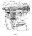
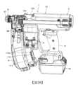
圖1A係表示本實施形態之緊固工具的內部構造之一例的側剖面圖,圖1B係表示本實施形態之緊固工具的內部構造之一例的上面剖面圖,圖1C係表示本實施形態之緊固工具的內部構造之一例的正面剖面圖。又,圖2A係表示本實施形態之緊固工具的內部構造之一例的分解立體圖,圖2B係表示本實施形態之緊固工具的一例之外觀立體圖。1A is a side sectional view showing an example of the internal structure of the fastening tool of this embodiment, FIG. 1B is a top sectional view showing an example of the internal structure of the fastening tool of this embodiment, and FIG. Front sectional view of an example of the internal structure of a fastening tool. 2A is an exploded perspective view showing an example of the internal structure of the fastening tool according to this embodiment, and FIG. 2B is an external perspective view showing an example of the fastening tool according to this embodiment.
本實施形態之緊固工具1係包括:起子頭保持部3,係將螺絲起子頭2固持成可旋轉及在軸向可移動;第1驅動部4,係使藉起子頭保持部3所固持之螺絲起子頭2旋轉;以及第2驅動部5,係使藉起子頭保持部3所固持之螺絲起子頭2在軸向移動。The
又,緊固工具1係包括:螺絲收納部6,係收容螺絲200;螺絲進給部7,係進給螺絲收納部6所收容之螺絲;以及鼻頭8,係被壓在螺絲200所鎖緊之緊固對象物,且射出螺絲。Also, the
進而,緊固工具1係具備工具本體10與把手11。又,緊固工具1係在把手11之端部,具備電池安裝部13,其係將電池12安裝成可拆裝。Furthermore, the
緊固工具1係工具本體10沿著以箭號A1、A2所示之螺絲起子頭2的軸向之一方向延伸,而把手11在與工具本體10的延伸方向交叉之其他的方向延伸。緊固工具1係將工具本體10之延伸方向,即,以箭號A1、A2所示之螺絲起子頭2的軸向當作前後方向。又,緊固工具1係將把手11之延伸方向當作上下方向。進而,緊固工具1將與工具本體10之延伸方向及把手11之延伸方向正交的方向當作左右方向。The
第1驅動部4係隔著把手11,被設置於後方,其係工具本體10之一側。第2驅動部5係隔著把手11,被設置於前方,其係工具本體10之另一側。The
螺絲收納部6係藉連結帶連結複數支螺絲200,並收容被捲繞成漩渦狀之連結螺絲。The
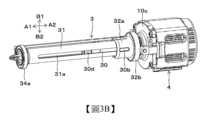
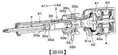
圖3A、圖3B係表示本實施形態之緊固工具的主要部構成之一例的立體圖,圖4A~圖4C係表示本實施形態之緊固工具的主要部構成之一例的剖面立體圖,圖5係表示本實施形態之緊固工具的主要部構成之一例的上面剖面圖,表示起子頭保持部3及第1驅動部4之細節。其次,參照各圖,說明起子頭保持部3及第1驅動部4。3A and FIG. 3B are perspective views showing an example of the main part of the fastening tool of this embodiment, and FIGS. 4A to 4C are cross-sectional perspective views showing an example of the main part of the fastening tool of this embodiment. A top sectional view showing an example of the configuration of the main parts of the fastening tool of this embodiment, showing the details of the
起子頭保持部3係包括:固持構件30,係將螺絲起子頭2固持成可拆裝;旋轉導引構件31,係將固持構件30支撐成向沿著螺絲起子頭2的軸向之以箭號A1、A2所示的前後方向可移動,且與固持構件30一起旋轉;移動構件32,係使固持構件30沿著導引構件31在前後方向移動;以及偏壓構件33,係將移動構件32向以箭號A2所示之後方向進行偏壓。The screwdriver
固持構件30係外徑比旋轉導引構件31之內徑稍小,並由被裝入旋轉導引構件31的內側之例如圓柱形的構件所構成。固持構件30係在沿著螺絲起子頭2的軸向之前側的端部,設置形狀與螺絲起子頭2之截面形狀一致的開口30a。固持構件30係在開口30a具備將螺絲起子頭2固持成可拆裝之拆裝固持機構30c。固持構件30係開口30a在旋轉導引構件31之內側露出,並將螺絲起子頭2可拆裝地插入開口30a。The
旋轉導引構件31係沿著工具本體10的延伸方向,即,沿著螺絲起子頭2的軸向之以箭號A1、A2所示的前後方向延伸。旋轉導引構件31係在內側裝入固持構件30之圓筒形,在金屬製的前框10b,經由是軸承之一例的軸承34a,將前側的端部支撐成可旋轉,該前框10b係被設置於樹脂製之殼體10a的前側,該殼體10a係構成工具本體10之殼體。又,旋轉導引構件31係將後側的端部與第1驅動部4連結。The
旋轉導引構件31係在與徑向相對向之側部的2個位置形成溝部31a,其係在沿著螺絲起子頭2的軸向之以箭號A1、A2所示的前後方向延伸。旋轉導引構件31係藉由將連結構件30b裝入溝部31a,而經由連結構件30b與固持構件30連結,該連結構件30b係在徑向貫穿固持構件30,並從固持構件30之兩側突出。The
固持構件30係設置孔部,其係對螺絲起子頭2之旋轉方向在垂直方向貫穿,並在該孔部插入連結構件30b,再以銷體30f固定。連結構件30b係由截面形狀為橢圓形之筒狀的構件所構成。The
連結構件30b係橢圓形之長邊方向為沿著與以箭號A1、A2所示之螺絲起子頭2的軸向平行之溝部31a的延伸方向之方向,橢圓形之短邊方向為與以箭號B1、B2方向所示之溝部31a的延伸方向正交之方向,即,沿著旋轉導引構件31之旋轉方向的方向。而且,連結構件30b係構成為橢圓形之短邊方向的寬度,即,沿著旋轉導引構件31之旋轉方向的寬度比溝部31a之沿著該方向的寬度稍小。The long side direction of the connecting
藉此,在溝部31a所裝入之連結構件30b係被溝部31a支撐成沿著旋轉導引構件31之軸向可移動。又,連結構件30b係對旋轉導引構件31沿著旋轉方向的移動在沿著溝部31a的延伸方向之溝部31a之一方的側面與另一方的側面之間受到限制。因此,連結構件30b係藉旋轉導引構件31旋轉的動作,因應於旋轉導引構件31之旋轉方向,被溝部31a之一方的側面或另一方的側面推,而從旋轉導引構件31承受是旋轉方向之圓周方向的力。Thereby, the
因此,固持構件30係旋轉導引構件31旋轉時,藉由連結構件30b被旋轉導引構件31之溝部31a推,而與旋轉導引構件31一起旋轉。又,固持構件30係連結構件30b被旋轉導引構件31之溝部31a引導,而在沿著螺絲起子頭2之軸向的前後方向移動。Therefore, when the
移動構件32係傳遞構件的一例,並包括:第1移動構件32a,係與固持構件30一起旋轉,並使固持構件30沿著旋轉導引構件31在前後方向移動;第2移動構件32c,係經由軸承32b被第1移動構件32a支撐,並經由軸承32b推第1移動構件32a;以及緩衝構件32d,係被安裝於第2移動構件32c之後側。The moving
第1移動構件32a係內徑比旋轉導引構件31之外徑稍大,並由被裝入旋轉導引構件31的外側之例如圓筒形的構件所構成。第1移動構件32a係藉由經由連結構件30b與固持構件30連結,被支撐成沿著旋轉導引構件31之軸向可移動,該連結構件30b係從旋轉導引構件31之溝部31a突出。The first moving
軸承32b係軸承之一例,被插入第1移動構件32a的外周與第2移動構件32c的內周之間。第1移動構件32a係構成固持軸承32b之內環的軸承內環固持構件,第2移動構件32c係構成固持軸承32b之外環的軸承外環固持構件。軸承32b係內環在第1移動構件32a之外周被支撐成無法在旋轉方向與軸向的移動,且外環在第2移動構件32c之內周被支撐成無法在旋轉方向與軸向的移動。The
藉此,第2移動構件32c係對第1移動構件32a,在向沿著軸向之前後方向的移動受到限制之狀態,經由軸承32b被連結。又,第2移動構件32c係經由軸承32b,將第1移動構件32a支撐成可旋轉。Thereby, the 2nd moving
因此,第1移動構件32a係藉第2移動構件32c在沿著軸向之前後方向移動的動作,經由軸承32b被第2移動構件32c推,而與第2移動構件32c一起在沿著軸向之前後方向移動。又,第1移動構件32a係對第2移動構件32c可旋轉,該第2移動構件32c係對旋轉導引構件31無法旋轉。Therefore, the first moving
偏壓構件33係在本例由彈簧所構成,在旋轉導引構件31之外側,被裝入前框10b與移動構件32的第2移動構件32c之間,並與彈簧座32f抵接,該前框10b係被設置於工具本體10之殼體10a的前側,該彈簧座32f係被配置成與軸承32b之外環的端面接觸。偏壓構件33係藉由移動構件32在以箭號A1所示之前方向移動而被壓縮,將移動構件32向以箭號A2所示之後方向進行偏壓。The biasing
第1驅動部4係包括:起子頭旋轉馬達40,係藉從電池12所供給之電力驅動;及減速機41。起子頭旋轉馬達40係第1馬達之一例,起子頭旋轉馬達40之軸40a與減速機41連結,而減速機41之軸41a與旋轉導引構件31連結。第1驅動部4係減速機41為利用行星齒輪的構成,並將起子頭旋轉馬達40配置成與旋轉導引構件31及固持構件30、以及固持構件30所固持之螺絲起子頭2位於同軸上。The
第1驅動部4係在金屬製的後框10c,安裝起子頭旋轉馬達40及減速機41,該後框10c係被設置於工具本體10之殼體10a的後側,減速機41之軸41a經由軸承42被後框10c支撐。旋轉導引構件31係後側的端部與減速機41之軸41a連結,而軸41a經由軸承42被後框10c支撐,藉此,經由是軸承之一例的軸承42,被支撐成可旋轉。The
起子頭保持部3與第1驅動部4係藉由以在前後方向延伸之連結構件10d連結前框10b與後框10c,被組裝成一體,並藉螺絲10e將前框10b固定於工具本體10之殼體10a。The
又,起子頭保持部3係旋轉導引構件31之前側的端部經由軸承34a被前框10b支撐,該前框10b係被固定於工具本體10之殼體10a的前側,而旋轉導引構件31之後側的端部經由減速機41之軸41a及軸承42被後框10c支撐,該後框10c係被固定於殼體10a的後側。因此,起子頭保持部3係旋轉導引構件31被工具本體10支撐成可旋轉。Also, the end portion of the
藉此,第1驅動部4係藉起子頭旋轉馬達40使旋轉導引構件31旋轉。固持螺絲起子頭2之固持構件30係旋轉導引構件31旋轉時,藉由連結構件30b被旋轉導引構件31之溝部31a推,而與旋轉導引構件31一起旋轉。Thereby, the
起子頭保持部3係在第2移動構件32c設置導引構件32g,連結構件10d係隔著比導引構件32g之直徑稍大的間隔,設置一對導引壁部10g,藉由將導引構件32g裝入一對導引壁部10g之間,而一對導引壁部10g與導引構件32g之周面相對向。The
藉此,第2移動構件32c係藉由導引構件32g被連結構件10d引導,而在沿著螺絲起子頭2的軸向之以箭號A1、A2所示的前後方向可移動,且追隨旋轉導引構件31之旋轉受到限制。Thereby, the second moving
圖6A及圖6B係表示本實施形態之緊固工具的內部構造之一例的上面剖面圖,並表示第2驅動部5之細節。接著,參照各圖,說明第2驅動部5。6A and 6B are top cross-sectional views showing an example of the internal structure of the fastening tool according to this embodiment, and show details of the
第2驅動部5係包括:起子頭旋轉馬達50,係藉從電池12所供給之電力驅動;及減速機51。起子頭旋轉馬達50係馬達、第2馬達之一例,起子頭旋轉馬達50之軸50a與減速機51連結,而減速機51之軸51a與是旋轉構件之一例的滑輪52連結。第2驅動部5係滑輪52經由軸承53被工具本體10支撐。第2驅動部5係沿著把手11的延伸方向配置起子頭移動馬達50的軸50a。The
第2驅動部5係是傳遞構件的一例之線狀之線材54的一端與滑輪52連結,藉由滑輪52旋轉,沿著滑輪52之外周52a捲繞線材54。又,線材54之另一端與線材連結部32h連結,該線材連結部32h係被設置於移動構件32之第2移動構件32c。傳遞構件係只要具有沿著滑輪52等之旋轉構件的外周被捲繞的撓性,由纖維等所構成之繩、由橡膠等所構成之皮帶、由金屬等所構成之鏈條都可。在傳遞構件由鏈條所構成的情況,亦可旋轉構件係具有齒部的鏈輪。The
藉此,第2驅動部5係藉起子頭旋轉馬達50使滑輪52旋轉,藉由捲繞線材54,使第2移動構件32c向以箭號A1所示之前方向移動。起子頭保持部3係藉由第2移動構件32c向前方向移動,經由軸承32b推第1移動構件32a,而第1移動構件32a與第2移動構件32c一起向沿著軸向之前方向移動。藉由第1移動構件32a向前方向移動,經由連結構件30b與第1移動構件32a連結的固持構件30向前方向移動,而固持構件30所固持之螺絲起子頭2向以箭號A1所示之前方向移動。Thereby, the
第2驅動部5係以在滑輪52捲繞線材54之部位的切線方向沿著旋轉導引構件31之延伸方向的方式,對緊固工具1之在左右方向的約中心,偏置地被配置於一側。即,在本例,是如下的配置,滑輪52之中心係起子頭移動馬達50之軸50a對旋轉導引構件31被偏置於一側,在從滑輪52之軸向觀察時,在滑輪52捲繞線材54之外周52a與旋轉導引構件31重疊。The
又,滑輪52與第2移動構件32c之間的線材54係如圖6A、圖6B所示,在滑輪52之徑向,以成為與旋轉導引構件31之軸向平行的方式,且如圖1A所示,在與滑輪52的徑向正交之起子頭移動馬達50的軸向,亦以與旋轉導引構件31之軸向成為平行的方式,配置滑輪52等。Also, the
進而,在滑輪52重疊地捲繞線材54時,因為從滑輪52之中心至線材54的距離因應於圈數而變化,所以滑輪52旋轉一圈時之螺絲起子頭2的移動量變化。又,在滑輪52與第2移動構件32c之間線材54所延伸之方向、與沿著旋轉導引構件31的軸向之螺絲起子頭2之移動方向的夾角變化。Furthermore, since the distance from the center of the
在此,以如下之方式設定滑輪52之直徑等,藉由使移動構件32在沿著一方向之可移動的範圍內從一方的端部移至另一方的端部,而為了使螺絲起子頭2移動既定量所需之滑輪52的旋轉量α成為未滿360°。Here, the diameter and the like of the
因此,為了使螺絲起子頭2移動既定量,藉滑輪52捲繞線材54的動作,如圖6B所示,在滑輪52不必重疊地捲繞線材54,而抑制螺絲起子頭2之移動量成為不正確。又,抑制在滑輪52與第2移動構件32c之間線材54的延伸方向、與沿著旋轉導引構件31的軸向之螺絲起子頭2的移動方向之平行度的變化。Therefore, in order to move the
因此,在固持構件30之可移動的範圍之整個區域,起子頭移動馬達50之旋轉量與固持構件30之移動量的關係成為一對一的關係,藉由控制起子頭移動馬達50之旋轉量,可控制沿著旋轉導引構件31的軸向之固持構件30的移動量。即,藉由控制起子頭移動馬達50之旋轉量,可控制在固持構件30所安裝之螺絲起子頭2的移動量。Therefore, in the entire region of the movable range of the holding
又,與線材54之捲繞量無關,作用於線材54之張力係總是與沿著旋轉導引構件31的軸向之螺絲起子頭2的移動方向成為平行,而可抑制螺絲起子頭2之移動及經由螺絲起子頭2推螺絲200之力的傳動效率之降低。Also, irrespective of the amount of winding of the
藉此,在滑輪52與第2移動構件32c之間的線材54沿著移動構件32的移動方向延伸成直線狀,而抑制藉滑輪52捲繞線材54時之負載的增加、從滑輪52拉出線材54時之負載的增加。Thereby, the
此外,線材54係因為具有可捲繞於滑輪52之撓性,所以不會有推第2移動構件32c而使移動構件32向後方移動的事。在此,具備偏壓構件33,其係藉由移動構件32向以箭號A1所示之前方向移動而被壓縮,並將向以箭號A2所示之後方向推移動構件32的力施加於移動構件32。藉此,在藉滑輪52捲繞線材54並使螺絲起子頭2前進的構成,可使前進後之螺絲起子頭2後退。In addition, since the
又,固持螺絲起子頭2之固持構件30係藉連結構件30b與溝部31a之卡合,被支撐成對旋轉導引構件31在前後方向可移動,且與旋轉導引構件31一起旋轉,該連結構件30b係被設置於固持構件30,該溝部31a係被設置於旋轉導引構件31。Also, the holding
因此,在將起子頭旋轉馬達40配置成與旋轉導引構件31及固持構件30、以及固持構件30所固持之螺絲起子頭2位於同軸上的構成,不必使起子頭旋轉馬達40在前後方向移動,可實現使螺絲起子頭2旋轉,且使螺絲起子頭2在前後方向移動的構成。Therefore, when the
此外,在將起子頭旋轉馬達40配置成與螺絲起子頭2位於同軸上的構成,係利用進給螺絲,將起子頭旋轉馬達40之旋轉動作變換成螺絲起子頭2之向前後方向的移動之構成。In addition, in the structure in which the
可是,在利用進給螺絲的構成,係因為馬達每轉之螺絲起子頭2的移動量無法獲取大,即使提高馬達之轉速,亦難使螺絲起子頭2之移動速度變快。However, in the configuration of using the feed screw, it is difficult to increase the moving speed of the
在緊固工具1,係為了縮短藉螺絲起子頭2將螺絲200壓至緊固對象物之時間,需要使螺絲起子頭2之移動速度變快,但是,在利用進給螺絲的構成,係難縮短藉螺絲起子頭2將螺絲200壓至緊固對象物之時間。In the
相對地,在固持螺絲起子頭2之固持構件30為被支撐成對旋轉導引構件31在前後方向可移動,並藉第2驅動部5使滑輪52旋轉,捲繞線材54,並使固持構件30在向前方向移動的構成,係因應於起子頭移動馬達50之轉速,可使螺絲起子頭2之移動速度變快。因此,可縮短藉螺絲起子頭2將螺絲200壓至緊固對象物之時間。In contrast, the holding
圖7A、圖7B係表示拆裝固持機構之一例的剖面圖,圖8A、圖8B係表示拆裝固持機構之一例的立體圖,並表示拆裝固持機構30c之細節。接著,參照各圖,說明拆裝固持機構30c。7A and 7B are sectional views showing an example of the dismounting and holding mechanism, and FIG. 8A and FIG. 8B are perspective views showing an example of the dismounting and holding mechanism, and show details of the dismounting and holding
拆裝固持機構30c係包括:在開口30a內露出之球體30d;及彈簧30e,係向在開口30a內露出之方向推壓球體30d。彈簧30e係推壓構件之一例,由板彈簧、線圈等之偏壓構件、橡膠等之彈性構件所構成,在本例,係由環形之板彈簧所構成,並與固持構件30之外周嵌合。The dismounting and holding
螺絲起子頭2之插入部20被插入固持構件30之開口30a時,拆裝固持機構30c係插入部20所推之球體30d一面使彈簧30e向環形之彈簧30e的直徑變大的方向變形,一面向固持構件30之外周方向退避。When the
在插入部20之外周所形成的溝部20a在將螺絲起子頭2之插入部20插入固持構件30的開口30a至與球體30d相對向的位置時,藉彈簧30e所偏壓之球體30d與溝部20a嵌合。藉此,抑制螺絲起子頭2從固持構件30意外地脫離。The
又,既定值以上之力向從固持構件30拔出螺絲起子頭2之方向作用時,一面使彈簧30e向環形之彈簧30e的直徑變大的方向變形,一面球體30d退避,藉此,可從固持構件30拔出螺絲起子頭2。Also, when a force above a predetermined value acts in the direction of pulling out the
在對固持構件30之開口30a插拔螺絲起子頭2之插入部20的動作,係球體30d向固持構件30之外周方向退避。因此,在固持構件30之外周,需要球體30d所退避的空間。另一方面,固持構件30係被插入筒形之旋轉導引構件31的內部,在固持構件30的外周與旋轉導引構件31的內周之間,係無法確保球體30d所退避的空間。When inserting and pulling out the
又,在固持構件30的外周與旋轉導引構件31的內周之間,為了確保球體30d所退避的空間,設定固持構件30與旋轉導引構件31之徑差時,因為螺絲起子頭2之徑向的尺寸已定,所以無法使固持構件30之外徑變小,而需要使旋轉導引構件31之外徑變大。因此,裝置變成大型化。Also, between the outer circumference of the holding
相對地,旋轉導引構件31係設置引導連結構件30b之溝部31a。溝部31a係從旋轉導引構件31之內周側向外周側貫穿表裡,並在旋轉導引構件31之軸向延伸。On the other hand, the
在此,拆裝固持機構30c係球體30d被設置成對準旋轉導引構件31之溝部31a的位置。即,固持構件30係在沿著旋轉導引構件31之軸向的同軸上設置連結構件30b、與拆裝固持機構30c之球體30d。藉此,拆裝固持機構30c係在旋轉導引構件31及固持構件30旋轉的動作、固持構件30對旋轉導引構件31在軸向移動的動作之任一動作,都球體30d在旋轉導引構件31之溝部31a露出。Here, the
因此,藉對固持構件30之開口30a插拔螺絲起子頭2之插入部20的動作,向固持構件30之外周方向退避的球體30d進入旋轉導引構件31之溝部31a。Therefore, when the
因此,在將固持構件30插入筒形之旋轉導引構件31之內部的構成,可確保拆裝固持機構30c之球體30d所退避的空間。又,藉由使連結構件30b所進入之溝部31a兼用作球體30d所退避的空間,抑制在旋轉導引構件31所設置之開口的面積,而可確保強度。Therefore, when the holding
進而,不必使固持構件30與旋轉導引構件31之徑差變大,以在固持構件30的外周與旋轉導引構件31的內周之間確保球體30d所退避的空間,而可抑制裝置之大型化。Furthermore, there is no need to increase the diameter difference between the holding
圖9係表示本實施形態之螺絲進給部及鼻頭之一例的立體圖,表示螺絲進給部7及鼻頭8之細節。接著,參照各圖,說明螺絲進給部7及鼻頭8。FIG. 9 is a perspective view showing an example of the screw feeder and nose of this embodiment, showing the details of the
螺絲進給部7係包括:螺絲進給馬達70;小齒輪71,係經由減速機被安裝於螺絲進給馬達70的軸;齒條72,係與小齒輪71嚙合;以及卡合部73,係與齒條72連結,並與從螺絲收納部6所進給之連結螺絲卡合。The
螺絲進給部7係齒條72被支撐成在沿著連結螺絲之進給方向的上下方向可移動。螺絲進給部7係藉由螺絲進給馬達70正轉及反轉,與連結螺絲卡合之卡合部73在上下方向移動,而連結螺絲被進給。The
鼻頭8係具有:射出通路80,藉螺絲進給部7供給螺絲200,且螺絲起子頭2所通過;接觸構件81,係具有與射出通路80連通之射出口81a,並與緊固對象物接觸;接觸臂82,係與接觸構件81連動,並在前後方向移動;以及調整部83,係限制接觸臂82之移動量。又,鼻頭8係具備覆蓋構件88,其係可開閉地覆蓋從螺絲收納部6至射出通路80之螺絲200所通過的路徑。The
緊固工具1係組裝構成射出通路80、接觸構件81以及接觸臂82之各零件,而構成鼻頭8,並被固定於構成工具本體10的前框10b及鼻本體部10f。又,緊固工具1係具備接觸開關部84,其係被接觸臂82推而動作。The
鼻頭8係接觸構件81被支撐成在以箭號A1、A2所示的前後方向可移動,接觸臂82與接觸構件81連動地在前後方向移動。鼻頭8係藉未圖示之偏壓構件將接觸構件81向前方向進行偏壓,被壓在緊固對象物並已向後方移動的接觸構件81被偏壓構件偏壓並向前方向移動。The
鼻頭8係接觸構件81被壓在緊固對象物,接觸臂82向後方移動,藉調整部83調整至接觸開關部84動作為止之接觸臂82的移動量。接觸開關部84係藉由被接觸臂82推而切換動作之有無,在本例,係將未被接觸臂82推而接觸開關部84未動作之狀態當作接觸開關部84之不導通(off),將被接觸臂82推而接觸開關部84動作之狀態當作接觸開關部84之導通(on)。The
接著,參照各圖,說明關於緊固工具1之控制及操作的構成。緊固工具1係包括:觸發器9,係接受操作;及觸發器開關部90,係藉觸發器9之操作而動作。觸發器9係被設置於把手11之前側,並構成為藉握持把手11之手的手指可操作。觸發器開關部90係被觸發器9推而動作。Next, the structure related to the control and operation of the
觸發器開關部90係藉由被觸發器9推而切換動作之有無,在本例,係將未操作觸發器9,觸發器9未推觸發器開關部90,而觸發器開關部90未動作之狀態當作觸發器開關部90之不導通(off),將操作觸發器9,被觸發器9推而觸發器開關部90動作之狀態當作觸發器開關部90之導通(on)。The
緊固工具1係具備控制部100,其係根據觸發器開關部90及接觸開關部84的輸出,控制第1驅動部4、第2驅動部5以及螺絲進給部7,該觸發器開關部90係藉觸發器9之操作而動作,該接觸開關部84係被接觸構件81推而動作。The
控制部100係由組裝各種電子零件之基板所構成,並在螺絲收納部6與把手11之間,被設置於基板收納部111,其係設置於螺絲收納部6之背面側。The
在以手握把手來使用之電動工具,係在把手之前方設置收容部,其係收容螺絲等之消耗品。而且,為了做成以手可握持把手,在把手與收容部之間,係需要手指所進入之空間。In the electric tool used by holding the handle, a storage part is provided in front of the handle to store consumables such as screws. Furthermore, in order to make the handle grippable by hand, a space for fingers to enter is required between the handle and the receiving portion.
在此,緊固工具1係利用螺絲收納部6與把手11之間的空間,在螺絲收納部6之背面側具備基板收納部111。Here, the
在以手握把手來使用之電動工具,係提議一種構成,其係在把手之下部安裝電池,且在把手與電池之間設置基板。若是這種構成,沿著把手的延伸方向之電動工具之在上下方向的尺寸擴大。In an electric tool that is used by holding a handle, a structure is proposed in which a battery is installed under the handle and a substrate is provided between the handle and the battery. With such a configuration, the dimension of the electric tool in the vertical direction increases along the extending direction of the handle.
相對地,藉由在螺絲收納部6之背面側具備基板收納部111,抑制沿著把手11的延伸方向之緊固工具1之在上下方向的尺寸擴大。又,螺絲收納部6係為了收容被捲繞成漩渦狀之連結螺絲,在螺絲收納部6,與把手11相對向的面係大致圓形。藉此,一面抑制緊固工具1之大型化,一面可確保基板收納部111之容積。On the other hand, by providing the
圖10A~圖10C係表示本實施形態之緊固工具的一例之從後方所觀察的立體圖,圖11係表示設定部之一例的立體圖,表示設定部110之細節。接著,參照各圖,說明設定部110。10A to 10C are perspective views showing an example of the fastening tool of this embodiment viewed from the rear, and FIG. 11 is a perspective view showing an example of a setting part, showing details of the setting
緊固工具1係具備使螺絲起子頭2在沿著軸向之前後方向移動的第2驅動部5,並是以下的構成,藉起子頭移動馬達50驅動第2驅動部5,藉線材54與滑輪52連結之移動構件32、及與移動構件32連結之固持構件30,沿著旋轉導引構件31,向沿著螺絲起子頭2之軸向的前方向移動,該滑輪52係被起子頭移動馬達50驅動而旋轉。The
藉此,藉由控制起子頭移動馬達50之旋轉量,可控制螺絲起子頭2之移動量(前進量)。即,藉由以與起子頭旋轉馬達40之旋轉連動的方式使起子頭移動馬達50旋轉,伴隨螺絲200之鎖緊,以起子頭移動馬達50之旋轉量控制追隨螺絲200而前進之螺絲起子頭2的前進量,可控制螺絲起子頭2之沿著軸向的停止位置,而該起子頭旋轉馬達40係在鎖緊螺絲200之方向使螺絲起子頭2旋轉。Thereby, by controlling the rotation amount of the
因此,緊固工具1係具備設定部110,其係設定螺絲起子頭2的前進量。設定部110係設定手段的一例,並構成為從複數個設定值中可選擇任意的設定值,或可無段地選擇任意的設定值。Therefore, the
設定部110係在本例,是利用由按鈕所構成之操作部110a選擇設定值的構成。又,亦可操作部110a係藉旋轉式之旋紐選擇設定值的構成。又,設定部110係為了作業員可易於掌握現在的設定值,亦可具備顯示設定值的構成,該設定值係利用以標籤或刻印等表示現在值之方法、或藉LED等之顯示部110b顯示現在值之方法等所選擇。In this example, the
設定部110係在基板收納部111,分別被設置於與把手11相對向之側的面之左右兩側,該基板收納部111係被設置於螺絲收納部6之背面側。The setting
藉此,在從後方觀察緊固工具1的情況,從把手11的左右兩側可目視設定部110。Thereby, when viewing the
在以手握把手11之使用形態,螺絲收納部6之與把手11相對向之側的面朝向握緊固工具1之作業員。藉此,在基板收納部111,藉由在與把手11相對向之側的面具備設定部110,在設定部110所設置之顯示部110b易進入視線,而該基板收納部111係被設置於螺絲收納部6之背面側。因此,減少作業員漏看顯示的可能性。此外,作為顯示於顯示部110b之內容,係不僅以螺絲起子頭2的前進量所規定之螺絲深度的設定值,還有電源之ON/OFF的狀態、從可選擇之各種運轉模式中所選擇的運轉模式、螺絲之有無、螺絲之殘留量、異常之有無等。In the use form of holding the
又,在以手握把手11之使用形態,在設定部110所設置之按鈕等的操作部110a亦易進入視線。因此,在以單手握把手11之狀態,一面目視操作部110a,一面以另一隻手可操作操作部110a,而可確實地操作。進而,在作業中不必改變姿勢或大為改變視線,就可看到顯示部110b,藉此,可防止在連續作業中未注意到警報等之通知。又,可防止因作業員欲注視顯示部110b或操作部110a,而未注意到射出口81a朝向作業員。In addition, in the use mode of holding the
進而,在基板收納部111,係收容構成控制部100之基板。在此基板,在與把手11相對向之側的面,藉由組裝構成操作部110a之開關類等、構成顯示部110b之燈類等,可省略與控制部100係另外之設定部110用的基板。 <本實施形態之緊固工具的動作例>Furthermore, the board|substrate which comprises the
圖12A係表示本實施形態之緊固工具的動作之一例的側剖面圖,圖12B係表示本實施形態之緊固工具的動作之一例的上面剖面圖,接著,參照各圖,說明本實施形態之緊固工具的鎖緊動作。12A is a side sectional view showing an example of the action of the fastening tool of this embodiment, and FIG. 12B is a top sectional view showing an example of the action of the fastening tool of this embodiment. Next, this embodiment will be described with reference to each figure. The locking action of the fastening tool.
緊固工具1係在待機狀態,如圖1A所示,螺絲起子頭2的頭端位於射出通路80之後方的待機位置P1,並向射出通路80可供給螺絲200。The
控制部100係將接觸構件81壓在緊固對象物,藉接觸臂82推接觸開關部84,而接觸開關部84成為導通,操作觸發器9,而觸發器開關部90成為導通時,驅動第2驅動部5之起子頭移動馬達50,且在既定時序,驅動第1驅動部4之起子頭旋轉馬達40。The
起子頭移動馬達50被驅動而向是一方向的正方向旋轉時,藉由滑輪52在正方向旋轉,而在滑輪52捲繞線材54。藉由在滑輪52捲繞線材54,與線材54連結之第2移動構件32c被旋轉導引構件31引導而向沿著軸向之前方向移動。第2移動構件32c向前方向移動時,第1移動構件32a經由軸承32b被第2移動構件32c推,而與第2移動構件32c一起一面壓縮偏壓構件33,一面向沿著軸向之前方向移動。When the
第1移動構件32a向前方向移動時,藉連結構件30b與第1移動構件32a連結之固持構件30在連結構件30b被旋轉導引構件31之溝部31a引導下,向沿著螺絲起子頭2之軸向的前方向移動。When the first moving
藉此,固持構件30所固持之螺絲起子頭2向以箭號A1所示之前方向移動,與在鼻頭8之射出口80所供給的螺絲200卡合,並使螺絲200向前方向移動,壓在緊固對象物。Thereby, the
起子頭旋轉馬達40被驅動而向是一方向的正方向旋轉時,旋轉導引構件31向正方向旋轉。旋轉導引構件31向正方向旋轉時,與固持構件30連結之連結構件30b被旋轉導引構件31之溝部31a推,藉此,固持構件30與旋轉導引構件31一起旋轉。When the
藉此,固持構件30所固持之螺絲起子頭2使螺絲200向正方向(順時鐘方向)旋轉,而螺入緊固對象物。控制部100係以與藉第1驅動部4使螺絲起子頭2旋轉而將螺絲螺入緊固對象物的動作連動的方式,根據作用於起子頭旋轉馬達40之負載、起子頭旋轉馬達40之旋轉圈數、作用於起子頭移動馬達50之負載、起子頭移動馬達50之旋轉圈數等,藉第2驅動部5使螺絲起子頭2向前方向移動,藉此,使螺絲起子頭2追隨被螺入緊固對象物之螺絲。Thereby, the
控制部100係如圖12A及圖12B所示,螺絲起子頭2之頭端從接觸構件81之射出口81a突出,並到達既定之動作結束位置P2時,停止起子頭旋轉馬達40之驅動,且使起子頭移動馬達50反轉。控制部100係根據起子頭移動馬達50之旋轉圈數,判斷螺絲起子頭2之頭端已到達動作結束位置P2。As shown in Figure 12A and Figure 12B, the
起子頭移動馬達50向是其他的方向之反方向旋轉時,藉由滑輪52在反方向旋轉,從滑輪52拉出線材54。因為從滑輪52拉出線材54,藉由第2移動構件32c向前方向移動所壓縮之偏壓構件33伸長,而向後方向推第2移動構件32c。When the
第2移動構件32c係藉偏壓構件33向後方向推,藉此,被旋轉導引構件31引導,而向沿著軸向之後方向移動。第2移動構件32c向後方向移動時,第1移動構件32a經由軸承32b被第2移動構件32c推,而與第2移動構件32c一起向沿著軸向之後方向移動。The second moving
第1移動構件32a向後方向移動時,藉連結構件30b與第1移動構件32a連結的固持構件30在連結構件30b被旋轉導引構件31之溝部31a引導下,向沿著螺絲起子頭2之軸向的後方向移動。When the first moving
藉此,固持構件30所固持之螺絲起子頭2向後方向移動,螺絲起子頭2的頭端回到待機位置P1。此外,移動構件32係藉由在第2移動構件32c之後側具備由橡膠等所構成之緩衝構件32d,藉第2移動構件32c向後方向移動的動作,抑制第2移動構件32c直接碰撞後框10c,而可抑制噪音之產生或損壞。控制部100係藉偏壓構件33向後方向推第2移動構件32c,而螺絲起子頭2的頭端回到待機位置P1時,停止起子頭移動馬達50之旋轉。控制部100係觸發器開關部90成為不導通時,藉由使螺絲進給馬達70向一方向旋轉,使卡合部73下降。卡合部73下降至與下一個螺絲200卡合之位置時,控制部100係藉由使螺絲進給馬達70反轉,使卡合部73上昇,向供給通路80供給下一個螺絲200。Accordingly, the
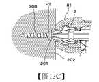
圖13A~圖13C係表示螺絲之鎖緊狀態的剖面圖,圖13A係表示螺絲200之頭部201從緊固對象物202之表面未浮起或埋沒之所謂的位於同一平面之狀態,圖13B係表示螺絲200之頭部201從緊固對象物202浮起之狀態,圖13C係表示螺絲200之頭部201埋入緊固對象物202之狀態。13A to 13C are cross-sectional views showing the locked state of the screw. FIG. 13A shows the so-called state where the
緊固工具1係在螺絲起子頭2的頭端已到達動作結束位置P2時,在螺絲200是平頭螺絲的情況,如圖13A所示,將螺絲起子頭2之前進量設定成螺絲200之頭部201的表面與緊固對象物202之表面成為相同之所謂的位於同一平面之狀態為佳。此外,螺絲200係不限定為平頭螺絲,若是圓頭螺絲、岡山頭螺絲、大扁頭螺絲等,將螺絲起子頭2之前進量設定成螺絲200之頭部201的座面與緊固對象物202之表面接觸,而螺絲200之頭部201不會成為從緊固對象物202浮起之狀態為佳。When the
螺絲起子頭2的頭端已到達動作結束位置P2時,在螺絲200之頭部201是如圖13B所示,從緊固對象物202浮起之狀態的情況,增加螺絲起子頭2之前進量,使動作結束位置P2前進即可。另一方面,在螺絲200之頭部201是如圖13C所示,埋入緊固對象物202之狀態的情況,減少螺絲起子頭2之前進量,使動作結束位置P2後退即可。When the head end of the
在此,做成藉設定部110可設定螺絲起子頭2之移動量(前進量)。螺絲起子頭2之移動量(前進量)係藉起子頭移動馬達50之旋轉圈數(旋轉量)所規定。而且,以是螺絲起子頭2之起始位置的待機位置P1為起點,使起子頭移動馬達50旋轉僅所設定之旋轉量後,使起子頭移動馬達50停止旋轉或反轉,藉此,控制動作結束位置P2。因此,可調整鎖入的深度。Here, the movement amount (advance amount) of the
1:緊固工具 10:工具本體 10a:殼體 10b:前框 10c:後框 10d:連結構件 10e:螺絲 10f:鼻本體部 11:把手 12:電池 13:電池安裝部 2:螺絲起子頭 3:起子頭保持部 30:固持構件 30a:開口 30b:連結構件 31:旋轉導引構件 31a:溝部 32:移動構件 32a:第1移動構件 32b:軸承 32c:第2移動構件 33:偏壓構件 34a:軸承 4:第1驅動部 40:起子頭旋轉馬達(第1馬達) 40a:軸 41:減速機 41a:軸 42:軸承 5:第2驅動部 50:起子頭移動馬達(馬達、第2馬達) 50a:軸 51:減速機 51a:軸 52:滑輪(旋轉構件) 52a:外周 53:軸承 54:線材(傳遞構件) 6:螺絲收納部 7:螺絲進給部 70:螺絲進給馬達 71:小齒輪 72:齒條 73:卡合部 8:鼻頭 80:射出通路 81:接觸構件 81a:射出口 82:接觸臂 83:調整部 84:接觸開關部 9:觸發器 90:觸發器開關部 100:控制部 110:設定部1: fastening tool 10:
圖1A係表示本實施形態之緊固工具的內部構造之一例的側剖面圖。 圖1B係表示本實施形態之緊固工具的內部構造之一例的上面剖面圖。 圖1C係表示本實施形態之緊固工具的內部構造之一例的正面剖面圖。 圖2A係表示本實施形態之緊固工具的內部構造之一例的分解立體圖。 圖2B係表示本實施形態之緊固工具的一例之外觀立體圖。 圖3A係表示本實施形態之緊固工具的主要部構成之一例的立體圖。 圖3B係表示本實施形態之緊固工具的主要部構成之一例的立體圖。 圖4A係表示本實施形態之緊固工具的主要部構成之一例的剖面立體圖。 圖4B係表示本實施形態之緊固工具的主要部構成之一例的剖面立體圖。 圖4C係表示本實施形態之緊固工具的主要部構成之一例的剖面立體圖。 圖5係表示本實施形態之緊固工具的主要部構成之一例的上面剖面圖。 圖6A係表示本實施形態之緊固工具的內部構造之一例的上面剖面圖。 圖6B係表示本實施形態之緊固工具的內部構造之一例的上面剖面圖。 圖7A係表示拆裝固持機構之一例的剖面圖。 圖7B係表示拆裝固持機構之一例的剖面圖。 圖8A係表示拆裝固持機構之一例的立體圖。 圖8B係表示拆裝固持機構之一例的立體圖。 圖9係表示本實施形態之螺絲進給部及鼻頭之一例的立體圖。 圖10A係表示本實施形態之緊固工具的一例之從後方所觀察的立體圖。 圖10B係表示本實施形態之緊固工具的一例之從後方所觀察的立體圖。 圖10C係表示本實施形態之緊固工具的一例之從後方所觀察的立體圖。 圖11係表示設定部之一例的立體圖。 圖12A係表示本實施形態之緊固工具的動作之一例的側剖面圖。 圖12B係表示本實施形態之緊固工具的動作之一例的上面剖面圖。 圖13A係表示螺絲之鎖緊狀態的剖面圖。 圖13B係表示螺絲之鎖緊狀態的剖面圖。 圖13C係表示螺絲之鎖緊狀態的剖面圖。Fig. 1A is a side sectional view showing an example of the internal structure of the fastening tool according to the present embodiment. Fig. 1B is a top sectional view showing an example of the internal structure of the fastening tool according to this embodiment. Fig. 1C is a front sectional view showing an example of the internal structure of the fastening tool according to this embodiment. Fig. 2A is an exploded perspective view showing an example of the internal structure of the fastening tool according to the present embodiment. Fig. 2B is an external perspective view showing an example of the fastening tool of this embodiment. Fig. 3A is a perspective view showing an example of the configuration of main parts of the fastening tool according to the present embodiment. Fig. 3B is a perspective view showing an example of the configuration of main parts of the fastening tool according to the present embodiment. Fig. 4A is a cross-sectional perspective view showing an example of the configuration of main parts of the fastening tool according to the present embodiment. Fig. 4B is a cross-sectional perspective view showing an example of the main part configuration of the fastening tool according to the present embodiment. Fig. 4C is a cross-sectional perspective view showing an example of the configuration of the main parts of the fastening tool according to the present embodiment. Fig. 5 is a top sectional view showing an example of the configuration of the main part of the fastening tool according to the present embodiment. Fig. 6A is a top sectional view showing an example of the internal structure of the fastening tool according to this embodiment. Fig. 6B is a top sectional view showing an example of the internal structure of the fastening tool according to this embodiment. Fig. 7A is a cross-sectional view showing an example of a detachable holding mechanism. Fig. 7B is a sectional view showing an example of the detachable and holding mechanism. Fig. 8A is a perspective view showing an example of a detachable and holding mechanism. Fig. 8B is a perspective view showing an example of the detachable holding mechanism. Fig. 9 is a perspective view showing an example of a screw feed portion and a nose piece in this embodiment. Fig. 10A is a perspective view showing an example of the fastening tool according to the present embodiment, as seen from the rear. Fig. 10B is a perspective view showing an example of the fastening tool according to the present embodiment as seen from the rear. Fig. 10C is a perspective view showing an example of the fastening tool according to the present embodiment as seen from the rear. Fig. 11 is a perspective view showing an example of a setting unit. Fig. 12A is a side sectional view showing an example of the operation of the fastening tool according to this embodiment. Fig. 12B is a top sectional view showing an example of the operation of the fastening tool of this embodiment. Fig. 13A is a cross-sectional view showing a locked state of a screw. Fig. 13B is a sectional view showing the locked state of the screw. Fig. 13C is a sectional view showing the locked state of the screw.
1:緊固工具1: fastening tool
2:螺絲起子頭2: Screwdriver head
3:起子頭保持部3: Screwdriver bit holder
4:第1驅動部4: The first drive unit
5:第2驅動部5: The second drive unit
6:螺絲收納部6: Screw storage part
8:鼻頭8: Nose
9:觸發器9: Trigger
10:工具本體10: Tool body
10a:殼體10a: shell
10b:前框10b: Front frame
10c:後框10c: rear frame
10f:鼻本體部10f: Nasal body
11:把手11: handle
12:電池12: battery
13:電池安裝部13: Battery installation department
20:插入部20: Insertion part
30:固持構件30: Holding member
30a:開口30a: opening
30b:連結構件30b: Connecting components
31:旋轉導引構件31: Rotation guide member
31a:溝部31a: Ditch
32:移動構件32: Mobile components
32a:第1移動構件32a: the first moving member
32b:軸承32b: Bearing
32c:第2移動構件32c: The second moving member
32d:緩衝構件32d: cushioning member
33:偏壓構件33: Bias member
34a:軸承34a: Bearing
40:起子頭旋轉馬達(第1馬達)40: Bit rotation motor (1st motor)
40a:軸40a: shaft
41:減速機41: reducer
41a:軸41a: Shaft
42:軸承42: Bearing
50:起子頭移動馬達(馬達、第2馬達)50: Bit moving motor (motor, 2nd motor)
50a:軸50a: shaft
51:減速機51: reducer
51a:軸51a: Shaft
52:滑輪(旋轉構件)52: pulley (rotating member)
53:軸承53: Bearing
54:線材(傳遞構件)54: wire (transfer component)
80:射出通路80: Injection channel
81:接觸構件81: Contact member
81a:射出口81a: Injection port
100:控制部100: Control Department
110:設定部110: Setting department
111:基板收納部111: Substrate storage part
200:螺絲200: screw
P1:待機位置P1: standby position
A1,A2:箭號A1,A2: Arrows
Claims (13)
Translated fromChineseApplications Claiming Priority (12)
| Application Number | Priority Date | Filing Date | Title |
|---|---|---|---|
| JP2021034725AJP7753645B2 (en) | 2021-03-04 | Fastening tool | |
| JP2021034723AJP7707579B2 (en) | 2021-03-04 | 2021-03-04 | Fastening tool |
| JP2021-034725 | 2021-03-04 | ||
| JP2021034722AJP7673427B2 (en) | 2021-03-04 | 2021-03-04 | Fastening Tools |
| JP2021034724AJP2022135118A (en) | 2021-03-04 | 2021-03-04 | fastening tool |
| JP2021-034723 | 2021-03-04 | ||
| JP2021-034724 | 2021-03-04 | ||
| JP2021-034722 | 2021-03-04 | ||
| JP2021-149654 | 2021-09-14 | ||
| JP2021149653AJP7703960B2 (en) | 2021-09-14 | 2021-09-14 | Fastening tool |
| JP2021149654AJP7700598B2 (en) | 2021-09-14 | 2021-09-14 | Fastening tool |
| JP2021-149653 | 2021-09-14 |
Publications (1)
| Publication Number | Publication Date |
|---|---|
| TW202300259Atrue TW202300259A (en) | 2023-01-01 |
Family
ID=80628456
Family Applications (6)
| Application Number | Title | Priority Date | Filing Date |
|---|---|---|---|
| TW111107919ATW202300257A (en) | 2021-03-04 | 2022-03-04 | fastening tool |
| TW111107915ATW202300255A (en) | 2021-03-04 | 2022-03-04 | fastening tool |
| TW111107916ATW202302285A (en) | 2021-03-04 | 2022-03-04 | fastening tool |
| TW111107922ATW202300259A (en) | 2021-03-04 | 2022-03-04 | fastening tool |
| TW111107917ATW202300256A (en) | 2021-03-04 | 2022-03-04 | fastening tool |
| TW111107920ATW202300258A (en) | 2021-03-04 | 2022-03-04 | fastening tool |
Family Applications Before (3)
| Application Number | Title | Priority Date | Filing Date |
|---|---|---|---|
| TW111107919ATW202300257A (en) | 2021-03-04 | 2022-03-04 | fastening tool |
| TW111107915ATW202300255A (en) | 2021-03-04 | 2022-03-04 | fastening tool |
| TW111107916ATW202302285A (en) | 2021-03-04 | 2022-03-04 | fastening tool |
Family Applications After (2)
| Application Number | Title | Priority Date | Filing Date |
|---|---|---|---|
| TW111107917ATW202300256A (en) | 2021-03-04 | 2022-03-04 | fastening tool |
| TW111107920ATW202300258A (en) | 2021-03-04 | 2022-03-04 | fastening tool |
Country Status (6)
| Country | Link |
|---|---|
| US (6) | US12214457B2 (en) |
| EP (7) | EP4052851A1 (en) |
| CN (6) | CN115008395A (en) |
| AU (4) | AU2022201520A1 (en) |
| ES (1) | ES2983016T3 (en) |
| TW (6) | TW202300257A (en) |
Families Citing this family (1)
| Publication number | Priority date | Publication date | Assignee | Title |
|---|---|---|---|---|
| TW202322984A (en)* | 2021-09-14 | 2023-06-16 | 日商美克司股份有限公司 | fastening tool |
Family Cites Families (83)
| Publication number | Priority date | Publication date | Assignee | Title |
|---|---|---|---|---|
| US3688966A (en) | 1969-11-10 | 1972-09-05 | Spotnails | Magazine and feed assembly for a fastener-driving tool |
| US3708097A (en) | 1971-03-18 | 1973-01-02 | Textron Inc | Nail feed mechanism |
| US3971421A (en) | 1974-02-26 | 1976-07-27 | Triad Fastener Corporation | Air-powered, self-feeding screw driving tool |
| US4367837A (en) | 1980-04-25 | 1983-01-11 | Manino Anthony P | Tape magazine feed apparatus for head driven fasteners |
| JPS59124579A (en)* | 1982-12-27 | 1984-07-18 | 室金属工業株式会社 | Continuous screw clamping machine |
| US4581964A (en) | 1985-02-22 | 1986-04-15 | Max Co. Ltd. | Fastener driving tool with improved magazine and feed mechanism |
| GB8704265D0 (en) | 1987-02-24 | 1987-04-01 | Yang T H | Manual electric tools(1) |
| JPS63300830A (en) | 1987-05-28 | 1988-12-08 | Nitto Seiko Co Ltd | Industrial robot screw tightening device |
| US4821937A (en) | 1987-09-14 | 1989-04-18 | Duo-Fast Corporation | Guide for fastener driving tool |
| JPH02232178A (en) | 1989-03-06 | 1990-09-14 | Masaki Kawashima | Fastener tightening machine |
| JPH0347781U (en) | 1989-09-14 | 1991-05-07 | ||
| DE3930999A1 (en) | 1989-09-16 | 1991-03-28 | Lorenz Stoeger | Screwdriver feed mechanism on robot - incorporates magazine for screws with mechanical conveyor to head |
| IT1248627B (en) | 1990-10-02 | 1995-01-21 | Umberto Monacelli | SCREWDRIVER FOR SCREWS CONNECTED BY A STRIP |
| US5144870A (en) | 1991-10-18 | 1992-09-08 | Nick Edward V | Apparatus for selectively installing fasteners |
| DE4334940C2 (en) | 1992-10-15 | 1996-10-31 | Max Co Ltd | Impact screw device |
| JP2894198B2 (en) | 1993-01-13 | 1999-05-24 | 株式会社デンソー | Screw fastening device |
| US5549169A (en) | 1993-01-13 | 1996-08-27 | Nippondenso Co., Ltd. | Screw tightening apparatus |
| DE4400709B4 (en) | 1993-01-13 | 2005-06-23 | Denso Corp., Kariya | Screw fastening device |
| JPH06312382A (en)* | 1993-04-28 | 1994-11-08 | Makita Corp | Drill bit storage structure for motor-driven tool |
| US5346453A (en) | 1993-08-12 | 1994-09-13 | Rivera Bottzeck Otto | Multiple bit power drill |
| JPH07241780A (en) | 1994-03-05 | 1995-09-19 | Muro Corp:Kk | Continuous machine screw fastening machine |
| JPH07266246A (en) | 1994-03-24 | 1995-10-17 | Max Co Ltd | Device for automatically stopping driving motor of thread fastener |
| EP0727284B1 (en) | 1995-02-15 | 2000-08-02 | Max Co., Ltd. | Screw driving machine with contact arm locking mechanism |
| JP3159016B2 (en)* | 1995-11-13 | 2001-04-23 | 株式会社ムロコーポレーション | Continuous screw tightening machine |
| EP1022096B1 (en) | 1995-11-20 | 2006-08-02 | Max Co., Ltd. | A screw guide mechanism of a screw driving and turning machine |
| AUPN741996A0 (en) | 1996-01-04 | 1996-01-25 | Interfix Limited | A driver |
| US5890405A (en) | 1996-09-11 | 1999-04-06 | Becker; Burkhard | Automated screw driving device |
| JP3405107B2 (en)* | 1997-01-31 | 2003-05-12 | マックス株式会社 | Pneumatic screw driving machine |
| JPH10235572A (en) | 1997-02-25 | 1998-09-08 | Matsushita Electric Works Ltd | Hand-held screw fastening machine |
| JPH10249750A (en)* | 1997-03-17 | 1998-09-22 | Muro Corp:Kk | Continuously machine screw fastening machine |
| JP2002239943A (en)* | 2001-02-14 | 2002-08-28 | Max Co Ltd | Fastener driver |
| JP2002346947A (en) | 2001-05-24 | 2002-12-04 | Max Co Ltd | Contact arm guide mechanism for nailer |
| JP3821005B2 (en)* | 2002-02-15 | 2006-09-13 | 日立工機株式会社 | Detachment device for driver bit of compressed air screw tightener |
| US20040006860A1 (en) | 2002-07-15 | 2004-01-15 | Haytayan Harry M. | Method and apparatus for attaching structural components with fasteners |
| DE20214489U1 (en) | 2002-09-19 | 2004-02-19 | Helfer & Co. Kg | Device for driving fasteners, in particular screws or the like. |
| US6655573B1 (en)* | 2002-11-18 | 2003-12-02 | Basso Industry Corp. | Screws dispensing device |
| JP2004249424A (en)* | 2003-02-21 | 2004-09-09 | Hitachi Koki Co Ltd | Connection screw tightening tool |
| JP4207700B2 (en)* | 2003-07-18 | 2009-01-14 | マックス株式会社 | Driving guide mechanism for nailing machine |
| US20050279517A1 (en) | 2004-06-21 | 2005-12-22 | Hoffman William H | Screw driving apparatus with attachable and detachable nose sub-assembly for use with single-feed screws or for use with automatic-feed collated screws |
| JP4802553B2 (en) | 2004-10-20 | 2011-10-26 | マックス株式会社 | Tar adhesion prevention mechanism for power driven nailers |
| US7055728B2 (en) | 2004-10-28 | 2006-06-06 | Basso Industry Corp. | Positioning structure for nailer |
| US6971567B1 (en) | 2004-10-29 | 2005-12-06 | Black & Decker Inc. | Electronic control of a cordless fastening tool |
| JP4577495B2 (en) | 2004-11-26 | 2010-11-10 | マックス株式会社 | Driving guide mechanism for screw and nail driving machines |
| US7225962B2 (en) | 2005-02-18 | 2007-06-05 | Illinois Tool Works Inc. | Nail advancement systems for nail arrays disposed within nailing tool magazines |
| DE102005000157B3 (en) | 2005-11-16 | 2007-04-05 | Hilti Ag | Manual nail gun, for driving nails or screws or bolts, has an electric drive to feed the fasteners into the chamber of the firing channel |
| TW200740569A (en) | 2006-04-24 | 2007-11-01 | Basso Ind Corp | Pushing flake structure of nail case |
| US7802500B2 (en)* | 2007-12-26 | 2010-09-28 | Illinois Tool Works, Inc. | Pneumatic fastener driving tool |
| TWI440530B (en)* | 2008-02-06 | 2014-06-11 | Max Co Ltd | Hand tool, nail residual detection mechanism, nail residual detection method, and power saving method |
| JP5262461B2 (en) | 2008-09-03 | 2013-08-14 | マックス株式会社 | Pneumatic screwing machine |
| TW201010829A (en) | 2008-09-08 | 2010-03-16 | Mobiletron Electronics Co Ltd | Automatic screw feeding apparatus for electricity powered screwdriver |
| JP5236606B2 (en)* | 2009-09-17 | 2013-07-17 | 三菱電機ビルテクノサービス株式会社 | Spanner equipment |
| JP5590505B2 (en) | 2009-09-30 | 2014-09-17 | 日立工機株式会社 | Driving machine |
| US8490516B2 (en) | 2009-09-30 | 2013-07-23 | Hitachi Koki Co., Ltd. | Screw driving machine having combustion-type power mechanism and electric power mechanism |
| US8894654B2 (en) | 2010-03-31 | 2014-11-25 | Smart Medical Devices, Inc. | Depth controllable and measurable medical driver devices and methods of use |
| DE102010030120A1 (en) | 2010-06-15 | 2011-12-15 | Hilti Aktiengesellschaft | driving- |
| DE102010063173A1 (en)* | 2010-12-15 | 2012-06-21 | Hilti Aktiengesellschaft | A bolt gun and method for operating a bolt gun |
| US8869656B2 (en)* | 2011-11-04 | 2014-10-28 | Senco Brands, Inc. | Screwdriver tool with improved corner fit function |
| EP3141351B1 (en) | 2012-01-13 | 2018-08-22 | Positec Power Tools (Suzhou) Co., Ltd | Power tool |
| TW201338936A (en) | 2012-03-28 | 2013-10-01 | Basso Ind Corp | Impact device of electrically-operated nail gun |
| TW201338933A (en)* | 2012-03-30 | 2013-10-01 | Basso Ind Corp | Electrical screw gun |
| DE102012206761A1 (en) | 2012-04-25 | 2013-10-31 | Hilti Aktiengesellschaft | Hand-held implement and method of operating a hand-held implement |
| TWI636856B (en) | 2013-07-04 | 2018-10-01 | 美克司股份有限公司 | Fastener tapping tool |
| JP6197547B2 (en)* | 2013-09-30 | 2017-09-20 | 日立工機株式会社 | Screwing machine |
| CN203680248U (en)* | 2013-11-28 | 2014-07-02 | 鸿富锦精密工业(深圳)有限公司 | Electric rotating tool |
| CN104972438B (en)* | 2014-04-10 | 2017-06-16 | 苏州宝时得电动工具有限公司 | Power tool |
| US20150306752A1 (en) | 2014-04-24 | 2015-10-29 | Basso Industry Corp. | Pneumatic nail gun |
| US20150336224A1 (en)* | 2014-05-26 | 2015-11-26 | Basso Industry Corp. | Anti-separating mechanism |
| JP6586777B2 (en) | 2015-05-27 | 2019-10-09 | 工機ホールディングス株式会社 | Driving machine |
| US10399193B2 (en) | 2017-01-25 | 2019-09-03 | The Boeing Company | Methods and apparatus to align threaded fasteners |
| CA2978391A1 (en) | 2017-09-07 | 2019-03-07 | Romp Coil Nail Industries Inc. | Staple advance device for stapler |
| JP6950423B2 (en) | 2017-09-29 | 2021-10-13 | マックス株式会社 | Driving tool |
| JP7144927B2 (en) | 2017-10-23 | 2022-09-30 | 株式会社マキタ | rotary tool |
| CN107914242A (en) | 2017-12-22 | 2018-04-17 | 王家宏 | Integral electric air pressure nailing gun |
| JP7231329B2 (en)* | 2018-02-19 | 2023-03-01 | 株式会社マキタ | screw tightening tool |
| JP2019155533A (en)* | 2018-03-13 | 2019-09-19 | 株式会社マキタ | Screw fastening tool |
| US10820911B2 (en) | 2018-05-17 | 2020-11-03 | Peninsula Surgical Solutions, Llc | Self-propelling surgical device |
| JP7035859B2 (en) | 2018-07-04 | 2022-03-15 | オムロン株式会社 | Screw tightening defect determination device, screw tightening system and program |
| JP6479248B1 (en) | 2018-12-11 | 2019-03-06 | 株式会社東日製作所 | Fastening device |
| US11273541B2 (en) | 2019-03-18 | 2022-03-15 | Kyocera Senco Industrial Tools, Inc. | Autofeed screwdriver attachment with twist collar to activate movable plates for latching to screw gun |
| JP7191751B2 (en)* | 2019-03-27 | 2022-12-19 | 株式会社マキタ | driving tool |
| WO2020195325A1 (en)* | 2019-03-27 | 2020-10-01 | オムロン株式会社 | Screw fastening failure determination device, screw fastening device, screw fastening failure determination method, and control program |
| JP7398894B2 (en)* | 2019-07-23 | 2023-12-15 | 株式会社マキタ | Tool holding device and electric working machine |
| CN110576405B (en) | 2019-08-15 | 2020-12-08 | 江西万上实业有限公司 | A screw gun for assembly |
- 2022
- 2022-03-04EPEP22160134.7Apatent/EP4052851A1/ennot_activeWithdrawn
- 2022-03-04USUS17/687,206patent/US12214457B2/enactiveActive
- 2022-03-04USUS17/687,447patent/US12186844B2/enactiveActive
- 2022-03-04CNCN202210213315.9Apatent/CN115008395A/enactivePending
- 2022-03-04ESES22160119Tpatent/ES2983016T3/enactiveActive
- 2022-03-04TWTW111107919Apatent/TW202300257A/enunknown
- 2022-03-04TWTW111107915Apatent/TW202300255A/enunknown
- 2022-03-04USUS17/686,981patent/US12186843B2/enactiveActive
- 2022-03-04CNCN202210213186.3Apatent/CN115008394A/enactivePending
- 2022-03-04EPEP22160138.8Apatent/EP4052852A1/enactivePending
- 2022-03-04CNCN202210212064.2Apatent/CN115091397A/enactivePending
- 2022-03-04EPEP22160119.8Apatent/EP4052848B1/enactiveActive
- 2022-03-04CNCN202210212163.0Apatent/CN115008392A/enactivePending
- 2022-03-04TWTW111107916Apatent/TW202302285A/enunknown
- 2022-03-04USUS17/687,099patent/US20220281088A1/ennot_activeAbandoned
- 2022-03-04TWTW111107922Apatent/TW202300259A/enunknown
- 2022-03-04CNCN202210212510.XApatent/CN115008393A/enactivePending
- 2022-03-04TWTW111107917Apatent/TW202300256A/enunknown
- 2022-03-04AUAU2022201520Apatent/AU2022201520A1/enactivePending
- 2022-03-04USUS17/687,033patent/US20220281084A1/enactivePending
- 2022-03-04EPEP24166431.7Apatent/EP4364893A3/enactivePending
- 2022-03-04CNCN202210213540.2Apatent/CN115008396A/enactivePending
- 2022-03-04AUAU2022201528Apatent/AU2022201528A1/enactivePending
- 2022-03-04USUS17/687,365patent/US20220281083A1/enactivePending
- 2022-03-04TWTW111107920Apatent/TW202300258A/enunknown
- 2022-03-04EPEP22160123.0Apatent/EP4052849A1/enactivePending
- 2022-03-04EPEP22160121.4Apatent/EP4104973B1/enactiveActive
- 2022-03-04EPEP22160125.5Apatent/EP4052850A1/enactivePending
- 2022-03-04AUAU2022201529Apatent/AU2022201529A1/enactivePending
- 2022-03-04AUAU2022201526Apatent/AU2022201526A1/enactivePending
Also Published As
Similar Documents
| Publication | Publication Date | Title |
|---|---|---|
| US20080251559A1 (en) | Portable Type Fastener Driving Tool | |
| US20220305625A1 (en) | Impact tool | |
| TW202300259A (en) | fastening tool | |
| JP2023042385A (en) | fastening tool | |
| JP7703960B2 (en) | Fastening tool | |
| NZ785849A (en) | Fastening tool | |
| US12350793B2 (en) | Fastening tool | |
| US20230330820A1 (en) | Fastening tool | |
| JP2022135117A (en) | fastening tool | |
| JP2022135118A (en) | fastening tool | |
| JP2022135116A (en) | fastening tool | |
| NZ785832A (en) | Fastening tool |