TW202300256A - fastening tool - Google Patents
fastening toolDownload PDFInfo
- Publication number
- TW202300256A TW202300256ATW111107917ATW111107917ATW202300256ATW 202300256 ATW202300256 ATW 202300256ATW 111107917 ATW111107917 ATW 111107917ATW 111107917 ATW111107917 ATW 111107917ATW 202300256 ATW202300256 ATW 202300256A
- Authority
- TW
- Taiwan
- Prior art keywords
- nose
- screw
- bit
- tool body
- fastening
- Prior art date
Links
- 238000002347injectionMethods0.000claimsdescription61
- 239000007924injectionSubstances0.000claimsdescription61
- 230000033001locomotionEffects0.000description19
- 239000003638chemical reducing agentSubstances0.000description12
- 230000009471actionEffects0.000description8
- 238000000034methodMethods0.000description8
- 230000005540biological transmissionEffects0.000description7
- 238000009434installationMethods0.000description7
- 230000007246mechanismEffects0.000description5
- 238000003780insertionMethods0.000description4
- 230000037431insertionEffects0.000description4
- 241000755266Kathetostoma giganteumSpecies0.000description3
- 238000002485combustion reactionMethods0.000description3
- 238000012546transferMethods0.000description3
- 230000002159abnormal effectEffects0.000description2
- 210000000078clawAnatomy0.000description2
- 230000008878couplingEffects0.000description2
- 238000010168coupling processMethods0.000description2
- 238000005859coupling reactionMethods0.000description2
- 238000010586diagramMethods0.000description2
- 230000006870functionEffects0.000description2
- 239000002184metalSubstances0.000description2
- 230000004048modificationEffects0.000description2
- 238000012986modificationMethods0.000description2
- 230000009467reductionEffects0.000description2
- 230000008859changeEffects0.000description1
- 230000006835compressionEffects0.000description1
- 238000007906compressionMethods0.000description1
- 230000003247decreasing effectEffects0.000description1
- 230000000694effectsEffects0.000description1
- 230000006872improvementEffects0.000description1
- 238000007689inspectionMethods0.000description1
- 238000012423maintenanceMethods0.000description1
- 239000000203mixtureSubstances0.000description1
- 230000035515penetrationEffects0.000description1
- 230000001960triggered effectEffects0.000description1
- 239000013585weight reducing agentSubstances0.000description1
Images


Classifications
- B—PERFORMING OPERATIONS; TRANSPORTING
- B25—HAND TOOLS; PORTABLE POWER-DRIVEN TOOLS; MANIPULATORS
- B25B—TOOLS OR BENCH DEVICES NOT OTHERWISE PROVIDED FOR, FOR FASTENING, CONNECTING, DISENGAGING OR HOLDING
- B25B21/00—Portable power-driven screw or nut setting or loosening tools; Attachments for drilling apparatus serving the same purpose
- B25B21/002—Portable power-driven screw or nut setting or loosening tools; Attachments for drilling apparatus serving the same purpose for special purposes
- B—PERFORMING OPERATIONS; TRANSPORTING
- B23—MACHINE TOOLS; METAL-WORKING NOT OTHERWISE PROVIDED FOR
- B23P—METAL-WORKING NOT OTHERWISE PROVIDED FOR; COMBINED OPERATIONS; UNIVERSAL MACHINE TOOLS
- B23P19/00—Machines for simply fitting together or separating metal parts or objects, or metal and non-metal parts, whether or not involving some deformation; Tools or devices therefor so far as not provided for in other classes
- B23P19/04—Machines for simply fitting together or separating metal parts or objects, or metal and non-metal parts, whether or not involving some deformation; Tools or devices therefor so far as not provided for in other classes for assembling or disassembling parts
- B23P19/06—Screw or nut setting or loosening machines
- B—PERFORMING OPERATIONS; TRANSPORTING
- B25—HAND TOOLS; PORTABLE POWER-DRIVEN TOOLS; MANIPULATORS
- B25B—TOOLS OR BENCH DEVICES NOT OTHERWISE PROVIDED FOR, FOR FASTENING, CONNECTING, DISENGAGING OR HOLDING
- B25B21/00—Portable power-driven screw or nut setting or loosening tools; Attachments for drilling apparatus serving the same purpose
- B25B21/001—Combined nut setting and crimping
- B—PERFORMING OPERATIONS; TRANSPORTING
- B23—MACHINE TOOLS; METAL-WORKING NOT OTHERWISE PROVIDED FOR
- B23B—TURNING; BORING
- B23B31/00—Chucks; Expansion mandrels; Adaptations thereof for remote control
- B23B31/02—Chucks
- B23B31/10—Chucks characterised by the retaining or gripping devices or their immediate operating means
- B23B31/12—Chucks with simultaneously-acting jaws, whether or not also individually adjustable
- B—PERFORMING OPERATIONS; TRANSPORTING
- B25—HAND TOOLS; PORTABLE POWER-DRIVEN TOOLS; MANIPULATORS
- B25B—TOOLS OR BENCH DEVICES NOT OTHERWISE PROVIDED FOR, FOR FASTENING, CONNECTING, DISENGAGING OR HOLDING
- B25B21/00—Portable power-driven screw or nut setting or loosening tools; Attachments for drilling apparatus serving the same purpose
- B25B21/02—Portable power-driven screw or nut setting or loosening tools; Attachments for drilling apparatus serving the same purpose with means for imparting impact to screwdriver blade or nut socket
- B25B21/023—Portable power-driven screw or nut setting or loosening tools; Attachments for drilling apparatus serving the same purpose with means for imparting impact to screwdriver blade or nut socket for imparting an axial impact, e.g. for self-tapping screws
- B—PERFORMING OPERATIONS; TRANSPORTING
- B25—HAND TOOLS; PORTABLE POWER-DRIVEN TOOLS; MANIPULATORS
- B25B—TOOLS OR BENCH DEVICES NOT OTHERWISE PROVIDED FOR, FOR FASTENING, CONNECTING, DISENGAGING OR HOLDING
- B25B23/00—Details of, or accessories for, spanners, wrenches, screwdrivers
- B25B23/0007—Connections or joints between tool parts
- B—PERFORMING OPERATIONS; TRANSPORTING
- B25—HAND TOOLS; PORTABLE POWER-DRIVEN TOOLS; MANIPULATORS
- B25B—TOOLS OR BENCH DEVICES NOT OTHERWISE PROVIDED FOR, FOR FASTENING, CONNECTING, DISENGAGING OR HOLDING
- B25B23/00—Details of, or accessories for, spanners, wrenches, screwdrivers
- B25B23/0064—Means for adjusting screwing depth
- B—PERFORMING OPERATIONS; TRANSPORTING
- B25—HAND TOOLS; PORTABLE POWER-DRIVEN TOOLS; MANIPULATORS
- B25B—TOOLS OR BENCH DEVICES NOT OTHERWISE PROVIDED FOR, FOR FASTENING, CONNECTING, DISENGAGING OR HOLDING
- B25B23/00—Details of, or accessories for, spanners, wrenches, screwdrivers
- B25B23/02—Arrangements for handling screws or nuts
- B25B23/04—Arrangements for handling screws or nuts for feeding screws or nuts
- B25B23/045—Arrangements for handling screws or nuts for feeding screws or nuts using disposable strips or discs carrying the screws or nuts
- B—PERFORMING OPERATIONS; TRANSPORTING
- B25—HAND TOOLS; PORTABLE POWER-DRIVEN TOOLS; MANIPULATORS
- B25B—TOOLS OR BENCH DEVICES NOT OTHERWISE PROVIDED FOR, FOR FASTENING, CONNECTING, DISENGAGING OR HOLDING
- B25B23/00—Details of, or accessories for, spanners, wrenches, screwdrivers
- B25B23/02—Arrangements for handling screws or nuts
- B25B23/04—Arrangements for handling screws or nuts for feeding screws or nuts
- B25B23/06—Arrangements for handling screws or nuts for feeding screws or nuts using built-in magazine
- B—PERFORMING OPERATIONS; TRANSPORTING
- B25—HAND TOOLS; PORTABLE POWER-DRIVEN TOOLS; MANIPULATORS
- B25B—TOOLS OR BENCH DEVICES NOT OTHERWISE PROVIDED FOR, FOR FASTENING, CONNECTING, DISENGAGING OR HOLDING
- B25B27/00—Hand tools, specially adapted for fitting together or separating parts or objects whether or not involving some deformation, not otherwise provided for
- B25B27/0085—Hand tools, specially adapted for fitting together or separating parts or objects whether or not involving some deformation, not otherwise provided for explosive-powered
- B—PERFORMING OPERATIONS; TRANSPORTING
- B25—HAND TOOLS; PORTABLE POWER-DRIVEN TOOLS; MANIPULATORS
- B25B—TOOLS OR BENCH DEVICES NOT OTHERWISE PROVIDED FOR, FOR FASTENING, CONNECTING, DISENGAGING OR HOLDING
- B25B27/00—Hand tools, specially adapted for fitting together or separating parts or objects whether or not involving some deformation, not otherwise provided for
- B25B27/14—Hand tools, specially adapted for fitting together or separating parts or objects whether or not involving some deformation, not otherwise provided for for assembling objects other than by press fit or detaching same
- B—PERFORMING OPERATIONS; TRANSPORTING
- B25—HAND TOOLS; PORTABLE POWER-DRIVEN TOOLS; MANIPULATORS
- B25C—HAND-HELD NAILING OR STAPLING TOOLS; MANUALLY OPERATED PORTABLE STAPLING TOOLS
- B25C1/00—Hand-held nailing tools; Nail feeding devices
- B25C1/06—Hand-held nailing tools; Nail feeding devices operated by electric power
- B—PERFORMING OPERATIONS; TRANSPORTING
- B25—HAND TOOLS; PORTABLE POWER-DRIVEN TOOLS; MANIPULATORS
- B25F—COMBINATION OR MULTI-PURPOSE TOOLS NOT OTHERWISE PROVIDED FOR; DETAILS OR COMPONENTS OF PORTABLE POWER-DRIVEN TOOLS NOT PARTICULARLY RELATED TO THE OPERATIONS PERFORMED AND NOT OTHERWISE PROVIDED FOR
- B25F5/00—Details or components of portable power-driven tools not particularly related to the operations performed and not otherwise provided for
- B25F5/02—Construction of casings, bodies or handles
Landscapes
- Engineering & Computer Science (AREA)
- Mechanical Engineering (AREA)
- Details Of Spanners, Wrenches, And Screw Drivers And Accessories (AREA)
- Dental Tools And Instruments Or Auxiliary Dental Instruments (AREA)
- Portable Nailing Machines And Staplers (AREA)
Abstract
Description
Translated fromChinese本發明涉及一種緊固工具,螺絲起子頭卡合於螺絲,藉由螺絲起子頭推螺絲而推抵緊固對象物,並且使螺絲起子頭被旋轉而旋入。The invention relates to a fastening tool. A screwdriver head is engaged with a screw, and the screwdriver head is pushed against a fastening object by the screwdriver head, and the screwdriver head is rotated to be screwed in.
已知一種被稱為可攜式打入機的工具,利用從空氣壓縮機供給的壓縮空氣的氣壓、和瓦斯的燃燒壓力,從驅動器導引件的頂端依序打出填裝於匣中的連結緊固件。There is known a tool called a portable driver, which sequentially drives out the joints filled in the cassette from the top of the driver guide by using the air pressure of the compressed air supplied from the air compressor and the combustion pressure of the gas. fastener.
一種螺絲打入機係被提案(例如,參照專利文獻1),作為利用瓦斯的燃燒壓力的打入機,為在打入機本體上安裝小型氣瓶可無線地(cordless)使用的打入機,使用螺絲作為被打入的連結緊固件。A screw driving machine has been proposed (for example, refer to Patent Document 1). As a driving machine utilizing the combustion pressure of gas, it is a driving machine that can be used cordlessly by attaching a small gas cylinder to the main body of the driving machine. , using screws as driven-in joint fasteners.
此外,一種螺絲打入機係被提案(例如,參照專利文獻2),藉由使螺絲旋轉的馬達的驅動力壓縮彈簧,藉由彈簧的偏壓打入螺絲。 [先行技術文獻] [專利文獻]In addition, a screw driving machine has been proposed (for example, refer to Patent Document 2) that compresses a spring by the driving force of a motor that rotates the screw, and drives the screw by the bias of the spring. [Prior Art Literature] [Patent Document]
[專利文獻1]日本專利第5590505號 [專利文獻2]日本專利第6197547號[Patent Document 1] Japanese Patent No. 5590505 [Patent Document 2] Japanese Patent No. 6197547
[發明欲解決的問題][Problem to be solved by the invention]
螺絲打入機係,包括導引構件的鼻部係被固定於外罩,其中,導引構件構成了成為起子頭的頂端來回移動時的通路、且成為螺絲被打出之射出孔的打擊通路。但是,在習知的螺絲打入機中,構成鼻部的各零件係,由於獨立而被安裝於外罩,所以在更換起子頭的情況下,必須將構成鼻部的複數個零件藉由既定的順序拆下,並且在更換起子頭之後,藉由既定的順序安裝,在起子頭的更換上係花費時間。又,在利用壓縮空氣的氣壓、和瓦斯的燃燒壓力的構成中,雖然亦有提案將與鼻為相反側的汽缸蓋分解而取出起子頭、進行起子頭的更換之構成,但在起子頭的更換上依然花費時間。Screw driving machine system, the nose system including the guide member is fixed to the outer cover, wherein the guide member constitutes the passage when the top end of the screwdriver head moves back and forth, and becomes the striking passage of the injection hole where the screw is driven out. However, in the known screw driving machine, each part system constituting the nose is mounted on the cover independently, so when replacing the screwdriver bit, it is necessary to replace the plurality of parts constituting the nose with a predetermined screwdriver. It is removed sequentially, and after replacing the bit, it is installed in a predetermined order, and time is spent on the replacement of the bit. In addition, in the configuration utilizing the air pressure of compressed air and the combustion pressure of gas, although there is also a proposal to disassemble the cylinder head on the opposite side to the nose, take out the screwdriver bit, and replace the screwdriver bit, but in the configuration of the screwdriver bit It still takes time to replace.
本發明係,為了解決如此之問題而完成的,以提供一種可容易更換起子頭為目的緊固工具。 [用於解決問題的手段]The present invention was made in order to solve such a problem, and aims to provide a fastening tool which can easily replace the bit of a driver. [means used to solve a problem]
為了解決上述問題,本發明係為一種緊固工具,將朝緊固對象物射出螺絲的鼻部,包括於沿著與螺絲卡合之螺絲起子頭的移動方向而朝一方向延伸的工具本體的前側。鼻部係包括:射出通路,被供給螺絲,並且螺絲起子頭係通過;以及接觸構件,接觸緊固對象物。鼻部係,射出通路與接觸構件被組裝成一體,可拆裝地被安裝於工具本體。In order to solve the above-mentioned problems, the present invention is a fastening tool that includes a nose portion that shoots a screw toward the fastened object on the front side of the tool body that extends in one direction along the moving direction of the screwdriver head engaged with the screw. . The nose system includes: an injection channel through which a screw is supplied and through which a screwdriver head system passes; and a contact member for contacting a fastening object. The nose system, the injection channel and the contact member are integrated and detachably attached to the tool body.
在本發明中,藉由從工具本體拆下鼻部,螺絲起子頭係從工具本體露出,進行螺絲起子頭的拆裝。In the present invention, by detaching the nose portion from the tool body, the screwdriver bit is exposed from the tool body, and the screwdriver bit is detached.
又,本發明係為一種緊固工具,將朝緊固對象物射出螺絲的鼻部,包括於沿著與螺絲卡合之螺絲起子頭的移動方向而朝一方向延伸的工具本體的前側。鼻部係包括:射出通路,螺絲起子頭係通過;螺絲進給部,朝射出通路供給螺絲;以及接觸構件,與射出通路連通並接觸緊固對象物。鼻部係可分離地構成為:第一鼻部,射出通路與接觸構件被組裝成一體;以及第二鼻部,包括螺絲進給部,被固定於工具本體。Further, the present invention is a fastening tool including a nose portion for projecting a screw toward a fastened object on the front side of the tool body extending in one direction along the moving direction of the screwdriver head engaged with the screw. The nose system includes: an injection channel through which a screwdriver head system passes; a screw feeding unit that supplies screws to the injection channel; and a contact member that communicates with the injection channel and contacts the fastening object. The nose part is detachably configured as follows: the first nose part, the injection passage and the contact member are assembled integrally; and the second nose part, including the screw feeding part, is fixed to the tool body.
在本發明中,藉由從被固定於工具本體的第二鼻部拆下第一鼻部,螺絲起子頭係從工具本體露出,進行螺絲起子頭的拆裝。 [發明效果]In the present invention, by detaching the first nose portion from the second nose portion fixed to the tool body, the screwdriver bit is exposed from the tool body, and the screwdriver bit is detached. [Invention effect]
在本發明中,鼻部係,構成為在將構成射出通路以及接觸構件的各零件單元化而組裝的狀態下可拆裝於工具本體。藉此,接觸構件等各零件並非獨立而固定於工具本體的構成,組裝性係提高,並且為易於從工具本體露出螺絲起子頭的構成,螺絲起子頭的更換作業變得容易。又,相較於各零件獨立而固定於工具本體的構成,各零件間的精度可提高。In the present invention, the nose part is configured to be detachable from the tool body in a state where components constituting the injection passage and the contact member are unitized and assembled. Thereby, components such as the contact member are not independently fixed to the tool body, which improves the assemblability, and the screwdriver bit is easily exposed from the tool body, which facilitates the replacement of the screwdriver bit. In addition, compared with the structure in which each part is independently fixed to the tool body, the precision between each part can be improved.
以下,請參照圖式,針對本發明的緊固工具的實施型態進行說明。Hereinafter, embodiments of the fastening tool of the present invention will be described with reference to the drawings.
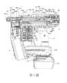
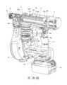
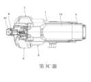
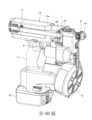
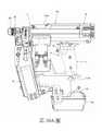
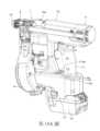
<本實施例的緊固工具的構成例> 第1圖係表示本實施例的緊固工具的內部構造之一例的側剖面圖,第2A圖至第2C圖係表示本實施例的緊固工具的內部構造之一例的一部分切開立體圖。又,第3A圖係表示本實施例的緊固工具之一例的側視圖,第3B圖係表示本實施例的緊固工具之一例的前視圖,第3C圖係表示本實施例的緊固工具之一例的俯視圖。並且,在第1圖中的剖面係,為第3B圖的A-A線段。此外,第4A圖至第4B圖係表示本實施例的緊固工具之一例的立體圖。<Configuration example of the fastening tool of this embodiment> Fig. 1 is a side sectional view showing an example of the internal structure of the fastening tool of this embodiment, and Figs. 2A to 2C are partially cutaway perspective views showing an example of the internal structure of the fastening tool of this embodiment. Also, Fig. 3A shows a side view of an example of a fastening tool of this embodiment, Fig. 3B shows a front view of an example of a fastening tool of this embodiment, and Fig. 3C shows a fastening tool of this embodiment A top view of an example. In addition, the cross section in Fig. 1 is the A-A line segment in Fig. 3B. 4A to 4B are perspective views showing an example of the fastening tool of this embodiment.
本實施例的緊固工具1係,包括工具本體10和把手11。緊固工具1係,把手11朝對於朝一方向延伸之工具本體10的延伸方向交叉之另一方向延伸。緊固工具1係,工具本體10的延伸方向為前後方向,把手11的延伸方向為上下方向。又,緊固工具1係,在把手11的下部包括電池安裝部13,電池12可拆卸地安裝在電池安裝部13。The
緊固工具1係,包括將螺絲起子頭2保持為可旋轉以及可沿著軸方向朝前後方向移動的起子頭保持部3,具有使藉由起子頭保持部3保持的螺絲起子頭2旋轉的第一驅動部4,以及具有使藉由起子頭保持部3保持的螺絲起子頭2、沿著軸方向朝前後方向移動的第二驅動部5。The
又,緊固工具1係,包括收納螺絲200的螺絲收納部6,用於進給被收納於螺絲收納部6的螺絲的螺絲進給部7,以及將螺絲推抵被緊固的緊固對象物、並且射出螺絲的鼻部8。In addition, the
起子頭保持部3係,包括將螺絲起子頭2保持為可拆裝自如的保持構件30,以將保持構件30支撐為可沿著螺絲起子頭2的軸方向朝前後方向移動、並且與保持構件30一起旋轉的旋轉導引構件31,使保持構件30沿著導引構件31朝前後方向移動的移動構件32,以及將移動構件32朝後方向偏壓的偏壓構件33。The
保持構件30係,藉由外徑比旋轉導引構件31的內徑稍微小,能進入旋轉導引構件31的內側之例如圓柱狀的構件而構成。保持構件30係,在沿著軸方向之前側的端部,設置有形狀與螺絲起子頭2的插入部20的截面形狀一致的開口30a。保持構件30在開口30a係包括,將螺絲起子頭2的插入部20藉由習知的機構保持為可拆裝的機構。保持構件30係,開口30a露出於旋轉導引構件31的內側,螺絲起子頭2的插入部20可拆裝地插入於開口30a。The
旋轉導引構件31係,為沿著工具本體10的延伸方向延伸、保持構件30進入內側之圓筒狀,前側的端部,在被設置於構成工具本體10的外殼之樹脂狀的殼體10a的前側的金屬製的前框10a,經由軸承34a被支撐為可旋轉。又,旋轉導引構件31係,後側的端部與第一驅動部4連結。The
旋轉導引構件31係,在與徑方向相向之側部的兩個位置處,形成沿著螺絲起子頭2的軸方向朝前後方向延伸的溝部31a。旋轉導引構件31係,在徑方向上貫穿保持構件30,藉由從保持構件30的兩側方突出的連結構件30b進入溝部31a,經由連結構件30b而與保持構件30連結。In the
藉此,保持構件30係,當旋轉導引構件31旋轉時,藉由連結構件30b被旋轉導引構件31的溝部31a推,與旋轉導引構件31一起旋轉。又,保持構件30係,連結構件30b在旋轉導引構件31的溝部31a被導引,沿著螺絲起子頭2的軸方向朝前後方向移動。Thereby, when the
移動構件32為傳遞構件之一例,係包括與保持構件30一起旋轉、使保持構件30沿著旋轉導引構件31朝前後方向移動的第一移動構件32a,經由軸承32b被第一移動構件32a支撐、藉由軸承32b推第一移動構件32a的第二移動構件32c,以及安裝在第二移動構件32c的後側的緩衝構件32d。The moving
第一移動構件32a係,藉由內徑比旋轉導引構件31的外徑稍微大,能進入旋轉導引構件31的外側之例如圓柱狀的構件而構成。第一移動構件32a係,經由從旋轉導引構件31的溝部31a突出的連結構件30b與保持構件30連結。The first moving
軸承32b係,插入第一移動構件32a的外周與第二移動構件32c的內周之間,相對於第二移動構件32c將第一移動構件32a支撐為可旋轉。The
第二移動構件32c係,在沿著軸方向朝前後方向的移動被限制的的狀態下,對於第一移動構件32a經由軸承32b而連結。The second moving
藉此,第一移動構件32a係,在第二移動構件32c沿著軸方向朝前後方向移動的動作中,經由軸承32b被第二移動構件32c推,與第二移動構件32c一起沿著軸方向朝前後方向移動。又,第一移動構件32a係,對於第二移動構件32c為可旋轉。Thereby, the first moving
偏壓構件33係,在本例中以線圈彈簧構成,在旋轉導引構件31的外側,進入設置於工具本體10的殼體10a的前側的前框10b與移動構件32的第二移動構件32c之間,抵接以與軸承32b的外圈的端面接觸的方式被配置之彈簧座。偏壓構件33係,藉由移動構件32朝前方向移動而被壓縮,對移動構件32施加將移動構件32朝後方向推之力。The biasing
第一驅動部4係,包括藉由電池12供給的電力驅動的起子頭旋轉馬達40,以及減速機41。起子頭旋轉馬達40是第一馬達之一例,起子頭旋轉馬達40的軸40a係,與減速機41連結,減速機41的軸41a係,與旋轉導引構件31連結。第一驅動部4係,減速機41利用行星齒輪而構成,藉此起子頭旋轉馬達40係與旋轉導引構件31以及被保持構件30保持的螺絲起子頭2配置於同軸上。The
第一驅動部4係,起子頭旋轉馬達40以及減速機41被安裝在設置於工具本體10的殼體10a的後側之金屬製的後框10c,減速機41的軸41a經由軸承42被支撐於後框10c。The
起子頭保持部3和第一驅動部4係,藉由將前框10b與後框10c以朝前後方向延伸的結合構件10d連結,組裝成一體而單元化,藉由螺絲10e被固定於工具本體10的殼體10a。起子頭保持部3與第一驅動部4係,構成為在各零件組裝的狀態下可自由拆裝於工具本體10,而不是藉由將各零件獨立地固定於工具本體10而構成,組裝性係提高。The
又,起子頭保持部3係,旋轉導引構件31的前側的端部是經由軸承34a被支撐於設置在工具本體10的殼體10a的前側的前框10b,旋轉導引構件31的後側的端部是經由減速機41的軸41a和軸承42被支撐於設置在殼體10a的後側的後框10c。因此,起子頭保持部3係,旋轉導引構件31被可旋轉地支撐於工具本體10。Also, in the
藉此,第一驅動部4係,藉由起子頭旋轉馬達40使旋轉導引構件31旋轉。旋轉導引構件31旋轉的話,藉由連結構件30b被旋轉導引構件31的溝部31a推,保持螺絲起子頭2的保持構件30係與旋轉導引構件31一起旋轉。Thereby, the
第二驅動部5係,包括藉由電池12供給的電力驅動的起子頭移動馬達50,以及減速機51。起子頭移動馬達50是馬達、第二馬達之一例,起子頭移動馬達50的軸50a係,與減速機51連結,減速機51的軸51a係與是傳遞構件之一例的滑輪52連結。第二驅動部5係,滑輪52經由軸承53被支撐於工具本體10。第二驅動部5係,起子頭移動馬達50的軸50a沿著把手11的延伸方向配置。The
第二驅動部5係,傳遞構件之一例的線材54纏繞於滑輪52,線材54連結於移動構件32的第二移動構件32c。In the
藉此,第二驅動部5係,藉由起子頭移動馬達50使滑輪52旋轉而捲繞線材54,使第二移動構件32c朝前方向移動。起子頭保持部3係,藉由第二移動構件32c朝前方向移動,第一移動構件32a經由軸承32b被推,第一移動構件32a與第二移動構件32c一起沿著軸方向朝前方向移動。藉由第一移動構件32a朝前方向移動,經由連結構件30b與第一移動構件32a而連結的保持構件30係朝前方向移動。Thereby, the
第二驅動部5係,滑輪52中之線材54纏繞之部位的切線方向為,以沿著旋轉導引構件31的延伸方向的方式,對於緊固工具1的左右方向之大致中心朝一方側偏移而配置。藉此,滑輪52與第二移動構件32c之間的線材W係,沿著移動構件32的移動方向以直線狀延伸,線材54被滑輪52捲繞時的負載增加、從滑輪52拉出線材W時的負載增加係被抑制。The
第一驅動部4係,包夾把手11,被設置在為工具本體10的一方側之後方。又,第二驅動部5係,包夾把手11,被設置在為工具本體10的另一方側之前方。The
螺絲收納部6係,複數個螺絲200藉由連結帶連結,纏繞成螺旋狀的連結螺絲被收納。There are 6 series of screw storage parts, and a plurality of
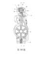
第5圖係表示本實施例的螺絲進給部的詳細情況的立體圖。螺絲進給部7係,包括螺絲進給馬達70,安裝在螺絲進給馬達70的軸的小齒輪71,與小齒輪71咬合的齒條72,以及與齒條72連結、與從螺絲收納部6進給的連結螺絲卡合的卡合部73。螺絲進給部7係,構成為藉由小齒輪71和齒條72,將螺絲進給馬達70的驅動力傳遞到卡合部73的螺絲進給傳遞部。卡合部73係,經由形成有齒條72的構件被未圖示的壓縮彈簧朝上方偏壓,以在不朝螺絲進給馬達70供給電源的狀態下、不會因卡合部73以及螺絲200的重量而下降的方式構成。Fig. 5 is a perspective view showing details of the screw feeding unit of this embodiment. The
螺絲進給部7係,螺絲進給馬達70固定於副框74,並且齒條72被副框74支撐為可沿著連結螺絲的進給方向朝上下方向移動。螺絲進給部7係,各零件藉由爪等凹凸形狀的嵌合、螺絲75的緊固等被組裝成一體而單元化。In the
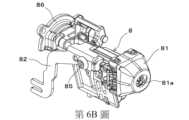
第6A圖、第6B圖係表示本實施例的鼻部之一例的立體圖。鼻部8是第一鼻部之一例,包括構成螺絲200被螺絲進給部7供給、並且螺絲起子頭2通過的射出通路80的射出通路構成部80a,具有與射出通路80連通的射出口81a、並接觸緊固對象物的接觸構件81,與接觸構件81連動而朝前後方向移動的接觸臂82,以及限制接觸臂82的移動量的調整部83。又,鼻部8係,包括可開關地覆蓋從螺絲收納部6至射出通路80之螺絲200通過的路徑的蓋構件88。Fig. 6A and Fig. 6B are perspective views showing an example of the nose of this embodiment. The
緊固工具1係,如第2C圖所示,包括被接觸臂82推而動作的接觸開關部84。又,緊固工具1係,如第1A圖所示,在工具本體10包括鼻本體部10f,在鼻本體部10f,包括藉由與鼻部8的射出通路構成部80a組合而構成射出通路80的射出通路構成部80b。鼻本體部10f是第二鼻部之一例,例如與前框10b構成為一體。並且,鼻本體部10f係,亦可構成為與前框10b為獨立的零件、被固定於前框10b。As shown in FIG. 2C , the
鼻部8係,接觸構件81被支撐為可朝前後方向移動,接觸臂82與接觸構件81連動而朝前後方向移動。鼻部8係,接觸構件81被未圖示的偏壓構件朝前方向偏壓,被推抵緊固對象物而朝後方移動的接觸構件81係,被偏壓構件偏壓而朝前方向移動。In the
鼻部8係,接觸構件81被推抵緊固對象物而接觸臂82朝後方移動,直到接觸開關部84動作為止之接觸臂82的移動量係藉由調整部83調整。接觸開關部84係,藉由被接觸臂82推而切換動作的有無。在本例中,將沒有被接觸臂82推、並且接觸開關部84非動作的狀態作為接觸開關部84的關閉,將當被接觸臂82推而接觸開關部84動作的狀態作為接觸開關部84的開啟。In the
鼻部8係,構成射出通路80、接觸構件81以及接觸臂82的各構件藉由爪等之凹凸形狀的嵌合、螺絲85的緊固等被一體組裝於副框86而單元化,藉由螺絲87被固定於構成工具本體10的前框10b。鼻部8被固定於前框10b的話,射出通路80係藉由被固定於工具本體10側的鼻本體部10f的射出通路構成部80b、以及為鼻部8側的零件之射出通路構成部80a構成。The
具有將鼻部8固定於工具本體10之功能的副框86係,形成有構成射出通路80的一部分的射出通路構成部80a,具有對於工具本體10進行射出通路80的位置定位之功能。藉此,將鼻部8固定於前框10b的話,射出通路構成部80a被正確地對準位置,即使鼻部8構成為對於工具本體10可拆裝,仍可抑制射出通路80對於螺絲起子頭2的移動路徑、特別是在徑方向的位置偏移之發生。又,接觸開關部84係,安裝在工具本體10側,當鼻部8固定於前框10b的話,接觸臂82之與接觸開關部84相對向之側的位置係,與接觸開關部84匹配。The
螺絲進給部7係,藉由與前框10b構成為一體、或者固定於前框10上,副框74藉由螺絲76被固定於構成工具本體10的鼻本體部10f。The
緊固工具1係,包括接收操作的觸發器9,以及藉由觸發器9的操作而動作的觸發器開關部90。觸發器9設置在把手11的前側,構成為握住把手11的手可伸指操作。觸發器開關部90係,被觸發器9推而動作。The
觸發器開關部90係,藉由被觸發器9推而切換動作的有無。在本例中,將觸發器9未被操作、觸發器開關部90未被觸發器9推之觸發器開關部90未動作的狀態作為觸發器開關部90的關閉,將觸發器9被操作、觸發器開關部90被觸發器9推而動作的狀態作為觸發器開關部90的開啟。The
緊固工具1係包括,基於藉由觸發器9的操作而動作的觸發器開關部90以及被接觸構件81推而動作的接觸開關部84的輸出,控制第一驅動部4、第二驅動部5以及螺絲進給部7的控制部100。在本例中,控制部100係被設置於設在把手11下部的電池安裝部13的內部。The
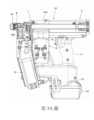
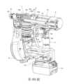
<本實施例的緊固工具的動作例> 第7圖係表示本實施例的緊固工具的動作之一例的側剖面圖,第8A圖、第8B圖係本實施例的緊固工具的動作之一例的一部分切開立體圖。以下,請參照各圖,針對本實施例的緊固工具的緊固動作進行說明。<Operation example of the fastening tool of this embodiment> Fig. 7 is a side sectional view showing an example of the operation of the fastening tool of this embodiment, and Figs. 8A and 8B are partially cutaway perspective views of an example of the operation of the fastening tool of this embodiment. Hereinafter, the fastening operation of the fastening tool according to this embodiment will be described with reference to the drawings.
緊固工具1係,在待機狀態下,如第1圖所示,螺絲起子頭2的頂端位於射出通路80的後方的待機位置P1,可朝射出通路80供給螺絲200。The
控制部100係,接觸構件81被緊固對象物推,接觸開關部84藉由接觸臂82被推而接觸開關部84成為開啟,當觸發器9被操作而觸發器開關部90成為開啟的話,驅動第二驅動部5的起子頭移動馬達50,並且在既定的時間點驅動第一驅動部4的起子頭旋轉馬達40。In the
當起子頭移動馬達50被驅動而朝為一方向之正方向旋轉的話,線材54藉由滑輪52朝正方向旋轉而被捲繞於滑輪52。藉由線材54被捲繞於滑輪52,與線材54連結的第二移動構件32c係,被旋轉導引構件31導引而沿著軸方向朝前方向移動。當第二移動構件32c朝前方向移動的話,第一移動構件32a經由軸承32b被第二移動構件32c推,與第二移動構件32c一同地,使偏壓構件33一邊壓縮一邊沿著軸方向朝前方向移動。When the
當第一移動構件32a朝前方向移動的話,藉由連結構件30b與第一移動構件32a連結的保持構件30係,連結構件30b被導引至旋轉導引構件31的溝部31a,而沿著螺絲起子頭2的軸方向朝前方向移動。When the first moving
藉此,被保持構件30保持的螺絲起子頭2係朝前方向移動,與被供給至鼻部8的射出口80的螺絲200卡合而使螺絲200朝前方向移動,推抵緊固對象物。Thereby, the
當起子頭旋轉馬達40被驅動而朝為一方向之正方向旋轉的話,旋轉導引構件31朝正方向旋轉。當旋轉導引構件31朝正方向旋轉的話,藉由與保持構件30連結的連結構件30b係被旋轉導引構件31的溝部31a推,保持構件30係與旋轉導引構件31一起旋轉。When the
藉此,被保持構件30保持的螺絲起子頭2使螺絲200朝正方向(順時針)旋轉,旋入緊固對象物。控制部100係,連動於藉由第一驅動部4使螺絲起子頭2旋轉而將螺絲旋入緊固對象物之動作,基於施加於起子頭旋轉馬達40的負載、起子頭旋轉馬達40的旋轉數、施加於起子頭移動馬達50的負載、起子頭移動馬達50的旋轉數等,藉由以第一驅動部5使螺絲起子頭2朝前方向移動,使螺絲起子頭2追隨被旋入緊固對象物的螺絲。Thereby, the
控制部100係,如第7圖所示,當螺絲起子頭2的頂端從接觸構件81的射出口81a突出並到達既定的動作結束位置P2的話,停止起子頭旋轉馬達40的驅動,並且使起子頭移動馬達50反轉。控制部100係,基於起子頭移動馬達50的旋轉數,判斷螺絲起子頭2的頂端已經到達動作結束位置P2亦可,基於施加於起子頭旋轉馬達40的負載、起子頭旋轉馬達40的旋轉數、施加於起子頭移動馬達50的負載、起子頭移動馬達50的旋轉數等,使動作結束位置P2為可變亦可。The
當起子頭移動馬達50朝為另一方向之反方向旋轉的話,線材54係藉由滑輪52朝反方向旋轉而從滑輪52被拉出。藉由從滑輪52拉出線材54,藉由第二移動構件32c朝前方向移動而被壓縮的偏壓構件33係伸長,第二移動構件32c被朝後方向推。When the
第二移動構件32c係,藉由偏壓構件33被朝後方向推,被導引至旋轉導引構件31而沿著軸方向朝後方向移動。當第二移動構件32c朝後方向移動的話,第一移動構件32a係經由軸承32b被第二移動構件32c拉,與第二移動構件32c一起沿著軸方向朝後方向移動。The second moving
當第一移動構件32a朝後方向移動的話,藉由連結構件30b與第一移動構件32a連結的保持構件30係,連結構件30b被導引至旋轉導引構件31的溝部31a,而沿著螺絲起子頭2的軸方向朝後方向移動。When the first moving
藉此,被保持構件30保持的螺絲起子頭2朝後方向移動,螺絲起子頭2的頂端係回到待機位置P1。並且,移動構件32係,藉由在第二移動構件32c的後側包括有橡膠等構成的緩衝構件32d,在第二移動構件32c朝後方向移動的動作中,可抑制第二移動構件32c直接抵接後框10c,而可抑制聲音的產生與損壞。控制部100係,當第二移動構件32c藉由偏壓構件33被朝後方向推、螺絲起子頭2的頂端回到待機位置P1的話,使起子頭移動馬達50的旋轉停止。控制部100係,當觸發器開關部90關閉的話,藉由使螺絲進給馬達70朝一方向旋轉,使卡合部73下降。當卡合部73下降至與下一個螺絲200卡合的位置的話,控制部100係,藉由使螺絲進給馬達70反轉,使卡合部73上升,將下一個螺絲200供給至供給通路80。Thereby, the
緊固工具1係,電池12可拆卸安裝在設置於把手11的電池安裝部13,包括藉由以從此電池12供給的電力驅動的起子頭旋轉馬達40使螺絲起子頭2旋轉的第一驅動部4,以及藉由以從電池12供給的電力驅動的起子頭移動馬達50、使螺絲起子頭2沿著軸方向朝前後方向移動的第二驅動部5。藉此,沒有必要如同藉由空氣壓驅動之緊固工具般連接軟管,作業性係提高。The
此外,緊固工具1係,藉由包括使螺絲起子頭2沿著軸方向朝前後方向移動的第二驅動部5,在接觸構件81突抵緊固對象物的狀態下,可使緊固工具1不朝接近緊固對象物之方向移動、進行螺絲的緊固。藉此,沒有必要如同通常的鑽頭起子或衝擊起子般,進行使工具本體朝接近緊固對象物的方向移動之動作,作業性係提高。In addition, the
此外,由於第二驅動部5係藉由起子頭移動馬達50的驅動力,將被卡合於螺絲起子頭2的螺絲推抵緊固對象物,所以可容易進行將螺絲推抵緊固對象物的力之過與不足的調整,以適當的力將螺絲推抵緊固對象物。In addition, since the
又,第一驅動部4係,包夾把手11,被設置在為工具本體10的一方側之後方,第二驅動部5係,包夾把手11,被設置在為工具本體10的另一方側之前方。藉此,在包夾把手11的前後分別具有馬達,而重量比較重的第一驅動部4以及第二驅動部5係被分散配置。於是,在藉由手握持把手11、工具本體10的延伸方向向著大致水平而進行緊固作業的情況下,包夾把手11前後的重量平衡變得大致均等,作業性係提高。Also, the
此外,第二驅動部5係,對於緊固工具1的左右方向之大致中心朝為一方側之左側偏移而配置,螺絲進給部7係,螺絲進給馬達70對於緊固工具1的左右方向之大致中心朝為另一方側之右側偏移而配置。藉此,左右的重量平衡也大致均等,作業性係提高。In addition, the
緊固工具1係,如上所述,使螺絲起子頭2旋轉的第一驅動部4、以及使螺絲起子頭2沿著軸方向朝前後方向移動的第二驅動部5係藉由獨立的馬達被驅動。藉此,相較於藉由單一驅動源進行兩個動作的構成,不需要驅動力的傳遞機構、在既定的時間點進行驅動力之傳遞的機構等,可以簡化構成。又,藉由簡化構成,可謀求輕量化。此外,可藉由控制進行兩個動作的連動。The
又,針對螺絲進給部7,也可以藉由將螺絲進給馬達70作為驅動源,而可藉由從電池12供給的電力驅動,不需要空氣壓的供給。此外,藉由螺絲進給部7以獨立於螺絲起子頭2的旋轉和移動的馬達驅動,相較於藉由單一驅動源執行兩個或三個動作的構成,可以簡化構成。又,可藉由控制進行複數個動作的連動。Furthermore, the
螺絲進給部7係,構成為在各零件被單元化而組裝的狀態下、可拆裝自如於構成工具本體10的鼻本體部10f。藉此,不是將螺絲進給馬達70等各零件獨立地固定於工具本體10之構成,組裝性係提高,且維修、檢查時的更換等容易進行。又,相較於各零件獨立地固定於工具本體10上的構成,可提高各零件間的精度。此外,被固定有螺絲進給部7的鼻本體部10f係,由於與構成工具本體10的前框10b成為一體或被固定於前框10b,所以可提高螺絲進給部7之對於工具本體10之安裝位置的精度。又,鼻本體部10f係,由於構成螺絲起子頭2通過之射出通路80的一部分,所以可提高螺絲進給部7之對於射出通路80之安裝位置的精度。The
第9A圖和第9B圖係表示本實施例的緊固工具中的螺絲起子頭拆裝動作之一例的立體圖,接下來,參照各圖,對拆裝螺絲起子頭2的動作進行說明。9A and 9B are perspective views showing an example of the screwdriver bit detachment operation in the fastening tool of this embodiment. Next, the operation of detaching the
緊固工具1係,如第1圖所示,位於待機位置P1之螺絲起子頭2的頂端係,位於鼻部8的深處,在接觸構件81的射出口81a不露出。在此,在更換螺絲起子頭2的情況下,拆裝鼻部8。
鼻部8的拆裝係,首先,卸下螺絲87。藉由卸下螺絲87,如第9B圖所示,可以從緊固工具1卸下鼻部8。鼻部8係,構成為在各零件組裝的狀態下可自由拆裝於工具本體10,覆蓋工具本體10的前側的端部的接觸構件81和構成射出口80的零件等係一體地被卸下。當從構成工具本體10的前框10b拆下鼻部8的話,為鼻部側8側的零件的射出通路構成部80a係,從固定於工具本體10側的鼻本體部10f的射出通路構成部80b被卸下,射出通路80係露出。To disassemble the
藉此,旋轉導引構件31的前側的端部在工具本體10的前側的端部露出,螺絲起子頭2係從旋轉導引構件31的前側的端部的開口露出。於是,藉由以鉗子等工具夾住螺絲起子頭並拉動,可將螺絲起子頭2從保持構件30卸下。Thus, the front end of the
螺絲起子頭2的安裝係,藉由使螺絲起子頭2從旋轉導引構件31的開口進入、並推入保持構件30的開口30a,使螺絲起子頭2被保持於保持構件30。然後,將鼻部8裝備在工具本體10的前側的端部,藉由緊固螺絲87,使鼻部8被固定於工具本體10。The mounting system of the
並且,在因第二驅動部5的減速機51的減速比的關係、使起子頭移動馬達50停止的狀態下,若是為即使對滑輪52施加外力,滑輪52也不旋轉的構成的話,亦可設置在使螺絲起子頭2的頂端從旋轉導引構件31突出既定量直到更換位置為止而使移動構件33移動的狀態下、停止起子頭移動馬達50的旋轉的起子頭更換模式。In addition, in the state where the
鼻部8係,構成為在構成射出通路80、接觸構件81以及接觸臂82的各零件被單元化而組裝的狀態下、可拆裝自如於工具本體10。藉此,不是將接觸臂82等各零件獨立地固定於工具本體10之構成,組裝性係提高。又,相較於各零件獨立地固定於工具本體10上的構成,可提高各零件間的精度。此外,需要配線的接觸開關部84係,藉由安裝於工具本體10側,不需要進行配線的連接或分離。The
<本實施例的緊固工具的變形例> 第10A圖係表示本實施例的緊固工具的變形例的側剖面圖,第10B圖係表示本實施例的緊固工具的另一變形例的側剖面圖,第11圖係表示本實施例的緊固工具的變形例的方塊圖。<Modification of the fastening tool of this embodiment> Figure 10A is a side sectional view showing a modified example of the fastening tool of this embodiment, Figure 10B is a side sectional view showing another modified example of the fastening tool of this embodiment, and Figure 11 is a side sectional view showing this embodiment A block diagram of a modification of the fastening tool.
緊固工具1係,如上所述,包括使螺絲起子頭2沿著軸方向朝前後方向移動的第二驅動部5,第二驅動部5藉由起子頭移動馬達50而被驅動,藉由線材54而與以起子頭移動馬達50驅動而旋轉的滑輪52連結的移動構件32、以及與移動構件32連結的保持構件30係構成為,沿著旋轉導引構件31,沿著螺絲起子頭2的軸方向朝前方向移動。藉此,藉由控制起子頭移動馬達50的旋轉量,可控制螺絲起子頭2的移動量(前進量)。也就是說,藉由連動於使螺絲起子頭2朝緊固螺絲200之方向旋轉之起子頭旋轉馬達40的旋轉、而使起子頭移動馬達50旋轉,藉由起子頭移動馬達50的旋轉量而控制伴隨著螺絲200的緊固、追隨螺絲200前進之螺絲起子頭2的前進量,進而可控制螺絲起子頭2沿著軸方向的停止位置。The
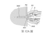
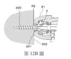
第12A圖至第12C圖係表示螺絲的緊固狀態的剖面圖,第12A圖係表示螺絲200的頭部201不從緊固對象物202的表面浮起或埋入之所謂的表面齊平的狀態,第12B圖係表示螺絲200的頭部201從緊固對象物202浮起的狀態,第12C圖係表示螺絲200的頭部201埋入緊固對象物202的狀態。12A to 12C are cross-sectional views showing the tightened state of the screw, and FIG. 12A shows the so-called flush surface in which the
緊固工具1係,當螺絲起子頭2的頂端到達動作結束位置P2時,在螺絲200為平頭螺絲的情況下,如第12A圖所示,較佳為以螺絲200的頭部201的表面係與緊固對象物202的表面成為同一個之所謂表面齊平之狀態的方式,設定螺絲起子頭2的前進量。並且,螺絲200不限於平頭螺絲,若為圓頭螺絲、岡山頭螺絲、大扁頭螺絲等的話,較佳為以螺絲200的頭部201的座面與緊固對象物202的表面相接、螺絲200的頭部201不從緊固對象物201浮起的狀態的方式,設定螺絲起子頭2的前進量。The
當螺絲起子頭2的頂端到達動作結束位置P2時,在螺絲200的頭部201係如第12B圖所示地從緊固對象物202浮起之狀態的情況下,增加螺絲起子頭2的前進量,而使動作結束位置P2前進即可。另一方面,當螺絲200的頭部201係如第12C圖所示埋入緊固對象物202之狀態的情況下,減少螺絲起子頭2的前進量,而使動作結束位置P2後退即可。When the top end of the
在此,包括了設定螺絲起子頭2的前進量的設定部110。設定部110是設定手段之一例,構成為可選擇複數個設定值,或者可藉由無段地選擇任何的設定值。設定部110係,例如如第10A圖所示,為藉由旋轉式的轉盤選擇設定值之構成。Here, the setting
在用於設定螺絲起子頭2的移動量(前進量)、設置專用的設定手段之方式之其中,在包括上述旋轉式的轉盤的構成之中,作為將作業員的操作轉換成電子訊號的手段,使用隨著轉盤連接的軸的旋轉角度而改變電阻值的電位計、和對應旋轉角度輸出脈衝的旋轉編碼器等的方式係被考慮。控制部100讀取這些電壓值和脈衝數,設定決定螺絲起子頭2的移動量(前進量)之起子頭移動馬達50的旋轉次數(旋轉量)。Among the methods for setting the movement amount (advance amount) of the
當被接觸臂82推而動作的接觸開關部84、與藉由觸發器9的操作而動作的觸發器開關部90雙方都開啟,成立螺絲緊固開始的條件的情況下,將為螺絲起子頭2的初始位置之待機位置P1作為起點,使起子頭移動馬達50僅旋轉設定的旋轉量之後,藉由使之旋轉停止或反轉,控制動作結束位置P2,而可調整緊固進入深度。When both the
又,設定部110係,如第10B圖所示,構成為藉由按鈕選擇設定值亦可。在使用按鈕等藉由按下而動作的開關的方式中,例如使用複數個,在本例中為使用兩個觸動開關(瞬時開關),對應被按下的開關而設定起子頭移動馬達50的旋轉次數(旋轉量)之方式係被考慮。在這種方式的情況下,一旦切斷工具本體的電源的話,因為在下次打開電源時前次的設定值係變成不明,使用電子抹除式可複寫唯讀記憶體(EEPROM)等儲存元件來儲存設定值係也被考慮。In addition, the
設定部110係,為槓桿式的開關、或觸控面板亦可。此外,設定部110係,為組合複數個設定手段亦可,例如,組合上述的轉盤方式與開關方式亦可。在這種情況下,可藉由轉盤操作來調整緊固進入量,並且在臨時擊打角落等必須傾斜擊打的情況下,藉由開關的操作而可設定緊固進入量的深度亦可。The
此外,設定部110係,為了使作業員可容易掌握現在的設定值,包括藉由以標籤、刻記號等顯示現在值的方法、或藉由以LED等顯示現在值的方法等,表示被選擇的設定值之構成亦可。並且,為了防止因雜訊等之設定誤判斷,僅在起子頭移動馬達50停止時檢測設定訊號亦可。又,由於考慮到因電位器故障、而顯示在通常的操作範圍外的異常電壓,不採用異常值,或藉由LED或蜂鳴器等將故障告知作業員係也被考慮。In addition, the
在藉由使限位器的位置移動等之機械構成而調整螺絲起子頭2的前進量的構成中,在鼻部8的附近設置使限位器的位置移動的設定部亦可。相對於此,在本實施例的緊固工具1中,藉由控制起子頭移動馬達50的旋轉量,可電子地控制螺絲起子頭2的移動量(前進量)。因此,設置設定部110的位置之約束條件較少。在此,設定部110係,在第10A圖和第10B圖之例中,設置於被設在把手11的下部之電池安裝部13的一方的側部。並且,在藉由右手握持把手11的情況下,因為設定部110係變成藉由左手操作,所以設定部110設置在電池安裝部13的左側的側部之構成亦可。In the configuration in which the advancing amount of the
第13圖表示設定部之一例的俯視圖。第13圖所示的設定部110係,由於設置在第10B圖所示的緊固工具1,所以包括選擇使螺絲起子頭2的前進量階梯式地減少之設定值的按鈕110a,以及選擇使螺絲起子頭2的前進量階梯式地增加之設定值的按鈕110b。Fig. 13 shows a plan view of an example of the setting unit. The
又,設定部110係,為了使藉由按鈕110a的操作被選擇的設定值可視覺上辨識,包括導引圖110a1。導引圖110a1係,設置於按鈕110a亦可,設置於按鈕110a的附近亦可。同樣地,設定部110係,為了使藉由按鈕110b的操作被選擇的設定值可視覺上辨識,包括導引圖110b1。導引圖110b1係,設置於按鈕110b亦可,設置於按鈕110b的附近亦可。In addition, the
此外,設定部110係,包括表示被選擇的設定值的燈110c。燈110c是表示部之一例,藉由點亮複數個燈110c的數量,表示被選擇的設定值。例如,在使螺絲起子頭2的前進量減少的情況下,減少點亮的燈110c的數量,在使螺絲起子頭2的前進量增加的情況下,增加點亮的燈110c的數量。此外,燈110c的顏色係,對應設定值而變更亦可。In addition, the
為了設定螺絲起子頭2的移動量(前進量),除了設置專用的設定手段之方式之外,作為設定手段,使用接觸開關部84或觸發器開關部90亦可。在使用接觸開關部84或觸發器開關部90等現存的操作手段作為設定手段的方式中,藉由使接觸臂82或觸發器9進行與執行通常的緊固動作之操作相異的既定的設定操作,可設定起子頭移動馬達50的旋轉次數(旋轉量)。例如,當接觸臂82未動作,並且在既定時間內進行了既定次數之拉動、釋放觸發器9的連續操作的話,判斷為是設定起子頭移動馬達50的旋轉次數(旋轉量)的設定操作。具體而言,在每次重複僅觸發器9快速操作三次等既定的操作時、階梯式地調整緊固進入深度係被考慮。In order to set the movement amount (advance amount) of the
在使用接觸開關部84和觸發器開關部90等現存的操作手段作為設定手段的方式中,因為不需要用於調整緊固進入量之其他操作手段或設定手段,所以可使工具本體小型化、降低成本。In the method of using the existing operating means such as the
第14圖係表示本實施例的變形例的緊固工具的動作例的流程圖,接著,請參考各圖,針對設定螺絲起子頭2的前進量而進行緊固之動作進行說明。FIG. 14 is a flow chart showing an example of the operation of the tightening tool according to the modified example of this embodiment. Next, referring to each figure, the operation of setting the advancing amount of the
控制部100係,在第14圖的步驟SA1中,基於藉由設定部110選擇的設定值,設定規定螺絲起子頭2的前進量之起子頭移動馬達50的旋轉量。控制部100係,接觸構件81被緊固對象物推抵,接觸開關部84藉由接觸臂82被推,在步驟SA2中接觸開關部84成為開啟,觸發器9被操作,在步驟SA3中觸發器開關部90成為開啟,在步驟SA4中驅動第二驅動部5的起子頭移動馬達50,並且在步驟SA5中驅動第一驅動部4的起子頭旋轉馬達40。The
當起子頭移動馬達50被驅動而朝為一方向的正方向旋轉的話,藉由線材54與滑輪52連結的移動構件32以及與移動構件32連結的保持構件30係,沿著旋轉導引構件31,而沿著螺絲起子頭2的軸方向朝前方向移動。When the
藉此,被保持構件30保持的螺絲起子頭2係朝前方向移動,與被供給至鼻部8的射出口80之螺絲200卡合而使螺絲200朝前方向移動,推抵緊固對象物。Thereby, the
又,當起子頭旋轉馬達40被驅動朝為一方向之正方向旋轉的話,保持構件30係與旋轉導引構件31一起旋轉。Also, when the
藉此,被保持構件30保持的螺絲起子頭2使螺絲200朝正方向(順時針)旋轉,旋入緊固對象物。控制部100係,連動於藉由第一驅動部4使螺絲起子頭2旋轉而將螺絲旋入緊固對象物之動作,基於施加於起子頭旋轉馬達40的負載、起子頭旋轉馬達40的旋轉數、施加於起子頭移動馬達50的負載、起子頭移動馬達50的旋轉數等,藉由以第一驅動部5使螺絲起子頭2朝前方向移動,使螺絲起子頭2追隨被旋入緊固對象物的螺絲。Thereby, the
控制部100係,當在步驟SA6中之起子頭移動馬達50的旋轉量係成為藉由設定部110選擇的設定值、且螺絲起子頭2的頂端到達設定之動作結束位置P2的話,在步驟SA7中停止起子頭旋轉馬達40的驅動,並且在步驟SA8中使起子頭移動馬達50反轉。The
當起子頭移動馬達50朝為另一方向之反方向旋轉的話,藉由從滑輪52拉出線材54,移動構件32藉由偏壓構件33被朝後方向推,移動構件32以及與移動構件32連結的保持構件30係沿著旋轉導引構件31,而沿著螺絲起子頭2的軸方向朝後方向移動。When the
控制部100係,在步驟SA9中,當線材54從滑輪52拉出預定量直到初始位置為止地反轉起子頭移動馬達50直到初始位置為止的話,在步驟SA10中停止起子頭移動馬達50的反轉。The
藉此,被保持構件30保持的螺絲起子頭2朝後方向移動,螺絲起子頭2的頂端係回到待機位置P1。Thereby, the
在緊固工具1中,藉由控制起子頭移動馬達50的旋轉量,可控制螺絲起子頭2的移動量(前進量)。藉此,相較於藉由使限位器的位置移動等之機械構成而可調整螺絲起子頭2的前進量的構成,可藉由簡化的構成,高精度地調整螺絲起子頭2的頂端位置。因此,可抑制螺絲200的頭部201如第12B圖所示般從緊固對象物202浮起、如第12C圖所示般過於沉入緊固對象物202,可成為如第12A圖所示之所謂表面齊平之狀態,緊固工作後的完成品係變得漂亮。In the
第15A圖至第15D圖係表示設定部的設置位置的變形例的立體圖。如上所述,在本實施例的緊固工具1中,由於藉由控制起子頭移動馬達50的旋轉量、可電子地控制螺絲起子頭2的移動量(前進量),所以設置設定部110的位置之約束條件較少。15A to 15D are perspective views showing modified examples of the installation positions of the setting parts. As described above, in the
在此,在第15A圖中,設定部110係設置於被設在把手11的下部之電池安裝部13的上部。又,在第15B圖中,設定部110係設置於電池安裝部13的後部。藉由在電池安裝部13的上部或後部、將設定部110設置於左右方向的中央附近,可與握持把手11之慣用手無關地操作設定部110。Here, in FIG. 15A , the setting
此外,設定部110設置於工具本體10側亦可,在第15C圖中,設定部110係設置於工具本體10的側部。在藉由右手握持把手11的情況下,因為設定部110係變成藉由左手操作,所以設定部110構成為設置於工具本體10的左側的側部亦可。In addition, the setting
又,在第15D圖中,設定部110係設置在工具本體10的後部,在本例中,設置於覆蓋第一驅動部4的蓋部43的後部。藉由在工具本體10的後部、將設定部110設置於左右方向的中央附近,可與握持把手11之慣用手無關地操作設定部110。並且,設定部110設置於工具本體10的上部亦可。Also, in FIG. 15D , the
如此,由於螺絲起子頭2沿著軸方向的移動量之設定可藉由電子訊號進行,所以設定部110的配置之約束條件較少,考慮調整緊固進入深度的操作性之最佳化係容易。In this way, since the setting of the movement amount of the
1:緊固工具 10:工具本體 10a:殼體 10b:前框 10c:後框 10d:結合構件 10e:螺絲 10f:鼻本體部 11:把手 12:電池 13:電池安裝部 2:螺絲起子頭 20:插入部 3:起子頭保持部 30:保持構件 30a:開口 30b:連結構件 31:旋轉導引構件 31a:溝部 32:移動構件(傳遞構件) 32a:第一移動構件 32b:軸承 32c:第二移動構件 32d:緩衝構件 33:偏壓構件 34a:軸承 4:第一驅動部 40:起子頭旋轉馬達(第一馬達) 40a:軸 41:減速機 41a:軸 42:軸承 43:蓋部 5:第二驅動部 50:起子頭移動馬達(馬達、第二馬達) 50a:軸 51:減速機 51a:軸 52:滑輪(傳遞構件) 53:軸承 54:線材(傳遞構件) 6:螺絲收納部 7:螺絲進給部 70:螺絲進給馬達 71:小齒輪(螺絲進給傳遞部) 72:齒條(螺絲進給傳遞部) 73:卡合部 74:副框 75,76:螺絲 8:鼻部 80:射出通路 80a,80b:射出通路構成部 81:接觸構件 81a:射出口 82:接觸臂 83:調整部 84:接觸開關部 85:螺絲 86:副框 87:螺絲 88:蓋構件 9:觸發器 90:觸發器開關部 100:控制部 110:設定部 110a,110b:按鈕 110a1,110b1:導引圖 110c:燈 200:螺絲 201:頭部 202:緊固對象物 P1:待機位置 P2:動作結束位置1: fastening tool 10: Tool body 10a: Housing 10b: Front frame 10c: rear frame 10d: Combining components 10e: screw 10f: Nasal body 11: handle 12: battery 13: Battery installation department 2: Screwdriver head 20: Insertion part 3: Screwdriver bit holder 30: Hold member 30a: opening 30b: Connecting components 31: Rotation guide member 31a: Ditch 32: Mobile component (transfer component) 32a: first moving member 32b: Bearing 32c: second moving member 32d: cushioning member 33: Bias member 34a: Bearing 4: The first drive unit 40: Screwdriver head rotation motor (first motor) 40a: shaft 41: reducer 41a: Shaft 42: Bearing 43: Cover 5: The second drive unit 50: Screwdriver head moving motor (motor, second motor) 50a: shaft 51: reducer 51a: Shaft 52: pulley (transfer member) 53: Bearing 54: wire (transfer component) 6: Screw storage part 7: Screw feeding part 70: Screw feed motor 71: Pinion (screw feed transmission part) 72: rack (screw feed transmission part) 73:Catching part 74: sub-frame 75,76: screw 8: Nose 80: Injection channel 80a, 80b: Injection path configuration part 81: Contact member 81a: Injection port 82: contact arm 83: Adjustment department 84: contact switch part 85: screw 86: sub frame 87: screw 88: cover member 9: Trigger 90: Trigger switch part 100: Control Department 110: Setting department 110a, 110b: buttons 110a1, 110b1: guide map 110c: lights 200: screw 201: head 202: fastening object P1: standby position P2: Action end position
第1圖係表示本實施例的緊固工具的內部構造之一例的側剖面圖。 第2A圖係表示本實施例的緊固工具的內部構造之一例的一部分切開立體圖。 第2B圖係表示本實施例的緊固工具的內部構造之一例的一部分切開立體圖。 第2C圖係表示本實施例的緊固工具的內部構造之一例的一部分切開立體圖。 第3A圖係表示本實施例的緊固工具之一例的側視圖。 第3B圖係表示本實施例的緊固工具之一例的前視圖。 第3C圖係表示本實施例的緊固工具之一例的俯視圖。 第4A圖係表示本實施例的緊固工具之一例的立體圖。 第4B圖係表示本實施例的緊固工具之一例的立體圖。 第5圖係表示本實施例的螺絲進給部的詳細情況的立體圖。 第6A圖係表示本實施例的鼻部之一例的立體圖。 第6B圖係表示本實施例的鼻部之一例的立體圖。 第7圖係表示本實施例的緊固工具的動作之一例的側剖面圖。 第8A圖係表示本實施例的緊固工具的動作之一例的一部分切開立體圖。 第8B圖係表示本實施例的緊固工具的動作之一例的一部分切開立體圖。 第9A圖係表示本實施例的緊固工具中的螺絲起子頭拆裝動作之一例的立體圖。 第9B圖係表示本實施例的緊固工具中的螺絲起子頭拆裝動作之一例的立體圖。 第10A圖係表示本實施例的緊固工具的變形例的側剖面圖。 第10B圖係表示本實施例的緊固工具的另一變形例的側剖面圖。 第11圖係表示本實施例的緊固工具的變形例的方塊圖。 第12A圖係表示螺絲的緊固狀態的剖面圖。 第12B圖係表示螺絲的緊固狀態的剖面圖。 第12C圖係表示螺絲的緊固狀態的剖面圖。 第13圖係表示設定部之一例的俯視圖。 第14圖係表示本實施例的變形例的緊固工具的動作例的流程圖。 第15A圖係表示設定部的設置位置的變形例的立體圖。 第15B圖係表示設定部的設置位置的變形例的立體圖。 第15C圖係表示設定部的設置位置的變形例的立體圖。 第15D圖係表示設定部的設置位置的變形例的立體圖。Fig. 1 is a side sectional view showing an example of the internal structure of the fastening tool of this embodiment. Fig. 2A is a partially cutaway perspective view showing an example of the internal structure of the fastening tool of this embodiment. FIG. 2B is a partially cutaway perspective view showing an example of the internal structure of the fastening tool of this embodiment. FIG. 2C is a partially cutaway perspective view showing an example of the internal structure of the fastening tool of this embodiment. Fig. 3A is a side view showing an example of the fastening tool of this embodiment. Fig. 3B is a front view showing an example of the fastening tool of this embodiment. Fig. 3C is a plan view showing an example of the fastening tool of this embodiment. Fig. 4A is a perspective view showing an example of the fastening tool of this embodiment. Fig. 4B is a perspective view showing an example of the fastening tool of this embodiment. Fig. 5 is a perspective view showing details of the screw feeding unit of this embodiment. Fig. 6A is a perspective view showing an example of the nose of this embodiment. Fig. 6B is a perspective view showing an example of the nose of this embodiment. Fig. 7 is a side sectional view showing an example of the operation of the fastening tool of this embodiment. Fig. 8A is a partially cutaway perspective view showing an example of the operation of the fastening tool of this embodiment. Fig. 8B is a partially cutaway perspective view showing an example of the operation of the fastening tool of this embodiment. FIG. 9A is a perspective view showing an example of the screwdriver bit detachment operation in the fastening tool of this embodiment. FIG. 9B is a perspective view showing an example of the screwdriver bit detachment operation in the fastening tool of this embodiment. FIG. 10A is a side sectional view showing a modified example of the fastening tool of this embodiment. Fig. 10B is a side sectional view showing another modified example of the fastening tool of this embodiment. Fig. 11 is a block diagram showing a modified example of the fastening tool of this embodiment. FIG. 12A is a cross-sectional view showing a tightened state of screws. FIG. 12B is a cross-sectional view showing a tightened state of screws. FIG. 12C is a cross-sectional view showing a tightened state of screws. Fig. 13 is a plan view showing an example of a setting unit. Fig. 14 is a flowchart showing an example of the operation of the fastening tool according to the modified example of the present embodiment. FIG. 15A is a perspective view showing a modified example of the installation position of the setting unit. FIG. 15B is a perspective view showing a modified example of the installation position of the setting unit. FIG. 15C is a perspective view showing a modified example of the installation position of the setting unit. FIG. 15D is a perspective view showing a modified example of the installation position of the setting unit.
1:緊固工具1: fastening tool
10:工具本體10: Tool body
10a:殼體10a: Housing
10b:前框10b: Front frame
10f:鼻本體部10f: Nasal body
11:把手11: handle
12:電池12: battery
2:螺絲起子頭2: Screwdriver head
31:旋轉導引構件31: Rotation guide member
4:第一驅動部4: The first drive unit
6:螺絲收納部6: Screw storage part
8:鼻部8: Nose
80b:射出通路構成部80b: Injection passage configuration part
81:接觸構件81: Contact member
86:副框86: sub frame
Claims (9)
Translated fromChineseApplications Claiming Priority (12)
| Application Number | Priority Date | Filing Date | Title |
|---|---|---|---|
| JP2021034725AJP7753645B2 (en) | 2021-03-04 | Fastening tool | |
| JP2021034723AJP7707579B2 (en) | 2021-03-04 | 2021-03-04 | Fastening tool |
| JP2021-034725 | 2021-03-04 | ||
| JP2021034722AJP7673427B2 (en) | 2021-03-04 | 2021-03-04 | Fastening Tools |
| JP2021034724AJP2022135118A (en) | 2021-03-04 | 2021-03-04 | fastening tool |
| JP2021-034723 | 2021-03-04 | ||
| JP2021-034724 | 2021-03-04 | ||
| JP2021-034722 | 2021-03-04 | ||
| JP2021-149654 | 2021-09-14 | ||
| JP2021149653AJP7703960B2 (en) | 2021-09-14 | 2021-09-14 | Fastening tool |
| JP2021149654AJP7700598B2 (en) | 2021-09-14 | 2021-09-14 | Fastening tool |
| JP2021-149653 | 2021-09-14 |
Publications (1)
| Publication Number | Publication Date |
|---|---|
| TW202300256Atrue TW202300256A (en) | 2023-01-01 |
Family
ID=80628456
Family Applications (6)
| Application Number | Title | Priority Date | Filing Date |
|---|---|---|---|
| TW111107919ATW202300257A (en) | 2021-03-04 | 2022-03-04 | fastening tool |
| TW111107915ATW202300255A (en) | 2021-03-04 | 2022-03-04 | fastening tool |
| TW111107916ATW202302285A (en) | 2021-03-04 | 2022-03-04 | fastening tool |
| TW111107922ATW202300259A (en) | 2021-03-04 | 2022-03-04 | fastening tool |
| TW111107917ATW202300256A (en) | 2021-03-04 | 2022-03-04 | fastening tool |
| TW111107920ATW202300258A (en) | 2021-03-04 | 2022-03-04 | fastening tool |
Family Applications Before (4)
| Application Number | Title | Priority Date | Filing Date |
|---|---|---|---|
| TW111107919ATW202300257A (en) | 2021-03-04 | 2022-03-04 | fastening tool |
| TW111107915ATW202300255A (en) | 2021-03-04 | 2022-03-04 | fastening tool |
| TW111107916ATW202302285A (en) | 2021-03-04 | 2022-03-04 | fastening tool |
| TW111107922ATW202300259A (en) | 2021-03-04 | 2022-03-04 | fastening tool |
Family Applications After (1)
| Application Number | Title | Priority Date | Filing Date |
|---|---|---|---|
| TW111107920ATW202300258A (en) | 2021-03-04 | 2022-03-04 | fastening tool |
Country Status (6)
| Country | Link |
|---|---|
| US (6) | US12214457B2 (en) |
| EP (7) | EP4052851A1 (en) |
| CN (6) | CN115008395A (en) |
| AU (4) | AU2022201520A1 (en) |
| ES (1) | ES2983016T3 (en) |
| TW (6) | TW202300257A (en) |
Families Citing this family (1)
| Publication number | Priority date | Publication date | Assignee | Title |
|---|---|---|---|---|
| TW202322984A (en)* | 2021-09-14 | 2023-06-16 | 日商美克司股份有限公司 | fastening tool |
Family Cites Families (83)
| Publication number | Priority date | Publication date | Assignee | Title |
|---|---|---|---|---|
| US3688966A (en) | 1969-11-10 | 1972-09-05 | Spotnails | Magazine and feed assembly for a fastener-driving tool |
| US3708097A (en) | 1971-03-18 | 1973-01-02 | Textron Inc | Nail feed mechanism |
| US3971421A (en) | 1974-02-26 | 1976-07-27 | Triad Fastener Corporation | Air-powered, self-feeding screw driving tool |
| US4367837A (en) | 1980-04-25 | 1983-01-11 | Manino Anthony P | Tape magazine feed apparatus for head driven fasteners |
| JPS59124579A (en)* | 1982-12-27 | 1984-07-18 | 室金属工業株式会社 | Continuous screw clamping machine |
| US4581964A (en) | 1985-02-22 | 1986-04-15 | Max Co. Ltd. | Fastener driving tool with improved magazine and feed mechanism |
| GB8704265D0 (en) | 1987-02-24 | 1987-04-01 | Yang T H | Manual electric tools(1) |
| JPS63300830A (en) | 1987-05-28 | 1988-12-08 | Nitto Seiko Co Ltd | Industrial robot screw tightening device |
| US4821937A (en) | 1987-09-14 | 1989-04-18 | Duo-Fast Corporation | Guide for fastener driving tool |
| JPH02232178A (en) | 1989-03-06 | 1990-09-14 | Masaki Kawashima | Fastener tightening machine |
| JPH0347781U (en) | 1989-09-14 | 1991-05-07 | ||
| DE3930999A1 (en) | 1989-09-16 | 1991-03-28 | Lorenz Stoeger | Screwdriver feed mechanism on robot - incorporates magazine for screws with mechanical conveyor to head |
| IT1248627B (en) | 1990-10-02 | 1995-01-21 | Umberto Monacelli | SCREWDRIVER FOR SCREWS CONNECTED BY A STRIP |
| US5144870A (en) | 1991-10-18 | 1992-09-08 | Nick Edward V | Apparatus for selectively installing fasteners |
| DE4334940C2 (en) | 1992-10-15 | 1996-10-31 | Max Co Ltd | Impact screw device |
| JP2894198B2 (en) | 1993-01-13 | 1999-05-24 | 株式会社デンソー | Screw fastening device |
| US5549169A (en) | 1993-01-13 | 1996-08-27 | Nippondenso Co., Ltd. | Screw tightening apparatus |
| DE4400709B4 (en) | 1993-01-13 | 2005-06-23 | Denso Corp., Kariya | Screw fastening device |
| JPH06312382A (en)* | 1993-04-28 | 1994-11-08 | Makita Corp | Drill bit storage structure for motor-driven tool |
| US5346453A (en) | 1993-08-12 | 1994-09-13 | Rivera Bottzeck Otto | Multiple bit power drill |
| JPH07241780A (en) | 1994-03-05 | 1995-09-19 | Muro Corp:Kk | Continuous machine screw fastening machine |
| JPH07266246A (en) | 1994-03-24 | 1995-10-17 | Max Co Ltd | Device for automatically stopping driving motor of thread fastener |
| EP0727284B1 (en) | 1995-02-15 | 2000-08-02 | Max Co., Ltd. | Screw driving machine with contact arm locking mechanism |
| JP3159016B2 (en)* | 1995-11-13 | 2001-04-23 | 株式会社ムロコーポレーション | Continuous screw tightening machine |
| EP1022096B1 (en) | 1995-11-20 | 2006-08-02 | Max Co., Ltd. | A screw guide mechanism of a screw driving and turning machine |
| AUPN741996A0 (en) | 1996-01-04 | 1996-01-25 | Interfix Limited | A driver |
| US5890405A (en) | 1996-09-11 | 1999-04-06 | Becker; Burkhard | Automated screw driving device |
| JP3405107B2 (en)* | 1997-01-31 | 2003-05-12 | マックス株式会社 | Pneumatic screw driving machine |
| JPH10235572A (en) | 1997-02-25 | 1998-09-08 | Matsushita Electric Works Ltd | Hand-held screw fastening machine |
| JPH10249750A (en)* | 1997-03-17 | 1998-09-22 | Muro Corp:Kk | Continuously machine screw fastening machine |
| JP2002239943A (en)* | 2001-02-14 | 2002-08-28 | Max Co Ltd | Fastener driver |
| JP2002346947A (en) | 2001-05-24 | 2002-12-04 | Max Co Ltd | Contact arm guide mechanism for nailer |
| JP3821005B2 (en)* | 2002-02-15 | 2006-09-13 | 日立工機株式会社 | Detachment device for driver bit of compressed air screw tightener |
| US20040006860A1 (en) | 2002-07-15 | 2004-01-15 | Haytayan Harry M. | Method and apparatus for attaching structural components with fasteners |
| DE20214489U1 (en) | 2002-09-19 | 2004-02-19 | Helfer & Co. Kg | Device for driving fasteners, in particular screws or the like. |
| US6655573B1 (en)* | 2002-11-18 | 2003-12-02 | Basso Industry Corp. | Screws dispensing device |
| JP2004249424A (en)* | 2003-02-21 | 2004-09-09 | Hitachi Koki Co Ltd | Connection screw tightening tool |
| JP4207700B2 (en)* | 2003-07-18 | 2009-01-14 | マックス株式会社 | Driving guide mechanism for nailing machine |
| US20050279517A1 (en) | 2004-06-21 | 2005-12-22 | Hoffman William H | Screw driving apparatus with attachable and detachable nose sub-assembly for use with single-feed screws or for use with automatic-feed collated screws |
| JP4802553B2 (en) | 2004-10-20 | 2011-10-26 | マックス株式会社 | Tar adhesion prevention mechanism for power driven nailers |
| US7055728B2 (en) | 2004-10-28 | 2006-06-06 | Basso Industry Corp. | Positioning structure for nailer |
| US6971567B1 (en) | 2004-10-29 | 2005-12-06 | Black & Decker Inc. | Electronic control of a cordless fastening tool |
| JP4577495B2 (en) | 2004-11-26 | 2010-11-10 | マックス株式会社 | Driving guide mechanism for screw and nail driving machines |
| US7225962B2 (en) | 2005-02-18 | 2007-06-05 | Illinois Tool Works Inc. | Nail advancement systems for nail arrays disposed within nailing tool magazines |
| DE102005000157B3 (en) | 2005-11-16 | 2007-04-05 | Hilti Ag | Manual nail gun, for driving nails or screws or bolts, has an electric drive to feed the fasteners into the chamber of the firing channel |
| TW200740569A (en) | 2006-04-24 | 2007-11-01 | Basso Ind Corp | Pushing flake structure of nail case |
| US7802500B2 (en)* | 2007-12-26 | 2010-09-28 | Illinois Tool Works, Inc. | Pneumatic fastener driving tool |
| TWI440530B (en)* | 2008-02-06 | 2014-06-11 | Max Co Ltd | Hand tool, nail residual detection mechanism, nail residual detection method, and power saving method |
| JP5262461B2 (en) | 2008-09-03 | 2013-08-14 | マックス株式会社 | Pneumatic screwing machine |
| TW201010829A (en) | 2008-09-08 | 2010-03-16 | Mobiletron Electronics Co Ltd | Automatic screw feeding apparatus for electricity powered screwdriver |
| JP5236606B2 (en)* | 2009-09-17 | 2013-07-17 | 三菱電機ビルテクノサービス株式会社 | Spanner equipment |
| JP5590505B2 (en) | 2009-09-30 | 2014-09-17 | 日立工機株式会社 | Driving machine |
| US8490516B2 (en) | 2009-09-30 | 2013-07-23 | Hitachi Koki Co., Ltd. | Screw driving machine having combustion-type power mechanism and electric power mechanism |
| US8894654B2 (en) | 2010-03-31 | 2014-11-25 | Smart Medical Devices, Inc. | Depth controllable and measurable medical driver devices and methods of use |
| DE102010030120A1 (en) | 2010-06-15 | 2011-12-15 | Hilti Aktiengesellschaft | driving- |
| DE102010063173A1 (en)* | 2010-12-15 | 2012-06-21 | Hilti Aktiengesellschaft | A bolt gun and method for operating a bolt gun |
| US8869656B2 (en)* | 2011-11-04 | 2014-10-28 | Senco Brands, Inc. | Screwdriver tool with improved corner fit function |
| EP3141351B1 (en) | 2012-01-13 | 2018-08-22 | Positec Power Tools (Suzhou) Co., Ltd | Power tool |
| TW201338936A (en) | 2012-03-28 | 2013-10-01 | Basso Ind Corp | Impact device of electrically-operated nail gun |
| TW201338933A (en)* | 2012-03-30 | 2013-10-01 | Basso Ind Corp | Electrical screw gun |
| DE102012206761A1 (en) | 2012-04-25 | 2013-10-31 | Hilti Aktiengesellschaft | Hand-held implement and method of operating a hand-held implement |
| TWI636856B (en) | 2013-07-04 | 2018-10-01 | 美克司股份有限公司 | Fastener tapping tool |
| JP6197547B2 (en)* | 2013-09-30 | 2017-09-20 | 日立工機株式会社 | Screwing machine |
| CN203680248U (en)* | 2013-11-28 | 2014-07-02 | 鸿富锦精密工业(深圳)有限公司 | Electric rotating tool |
| CN104972438B (en)* | 2014-04-10 | 2017-06-16 | 苏州宝时得电动工具有限公司 | Power tool |
| US20150306752A1 (en) | 2014-04-24 | 2015-10-29 | Basso Industry Corp. | Pneumatic nail gun |
| US20150336224A1 (en)* | 2014-05-26 | 2015-11-26 | Basso Industry Corp. | Anti-separating mechanism |
| JP6586777B2 (en) | 2015-05-27 | 2019-10-09 | 工機ホールディングス株式会社 | Driving machine |
| US10399193B2 (en) | 2017-01-25 | 2019-09-03 | The Boeing Company | Methods and apparatus to align threaded fasteners |
| CA2978391A1 (en) | 2017-09-07 | 2019-03-07 | Romp Coil Nail Industries Inc. | Staple advance device for stapler |
| JP6950423B2 (en) | 2017-09-29 | 2021-10-13 | マックス株式会社 | Driving tool |
| JP7144927B2 (en) | 2017-10-23 | 2022-09-30 | 株式会社マキタ | rotary tool |
| CN107914242A (en) | 2017-12-22 | 2018-04-17 | 王家宏 | Integral electric air pressure nailing gun |
| JP7231329B2 (en)* | 2018-02-19 | 2023-03-01 | 株式会社マキタ | screw tightening tool |
| JP2019155533A (en)* | 2018-03-13 | 2019-09-19 | 株式会社マキタ | Screw fastening tool |
| US10820911B2 (en) | 2018-05-17 | 2020-11-03 | Peninsula Surgical Solutions, Llc | Self-propelling surgical device |
| JP7035859B2 (en) | 2018-07-04 | 2022-03-15 | オムロン株式会社 | Screw tightening defect determination device, screw tightening system and program |
| JP6479248B1 (en) | 2018-12-11 | 2019-03-06 | 株式会社東日製作所 | Fastening device |
| US11273541B2 (en) | 2019-03-18 | 2022-03-15 | Kyocera Senco Industrial Tools, Inc. | Autofeed screwdriver attachment with twist collar to activate movable plates for latching to screw gun |
| JP7191751B2 (en)* | 2019-03-27 | 2022-12-19 | 株式会社マキタ | driving tool |
| WO2020195325A1 (en)* | 2019-03-27 | 2020-10-01 | オムロン株式会社 | Screw fastening failure determination device, screw fastening device, screw fastening failure determination method, and control program |
| JP7398894B2 (en)* | 2019-07-23 | 2023-12-15 | 株式会社マキタ | Tool holding device and electric working machine |
| CN110576405B (en) | 2019-08-15 | 2020-12-08 | 江西万上实业有限公司 | A screw gun for assembly |
- 2022
- 2022-03-04EPEP22160134.7Apatent/EP4052851A1/ennot_activeWithdrawn
- 2022-03-04USUS17/687,206patent/US12214457B2/enactiveActive
- 2022-03-04USUS17/687,447patent/US12186844B2/enactiveActive
- 2022-03-04CNCN202210213315.9Apatent/CN115008395A/enactivePending
- 2022-03-04ESES22160119Tpatent/ES2983016T3/enactiveActive
- 2022-03-04TWTW111107919Apatent/TW202300257A/enunknown
- 2022-03-04TWTW111107915Apatent/TW202300255A/enunknown
- 2022-03-04USUS17/686,981patent/US12186843B2/enactiveActive
- 2022-03-04CNCN202210213186.3Apatent/CN115008394A/enactivePending
- 2022-03-04EPEP22160138.8Apatent/EP4052852A1/enactivePending
- 2022-03-04CNCN202210212064.2Apatent/CN115091397A/enactivePending
- 2022-03-04EPEP22160119.8Apatent/EP4052848B1/enactiveActive
- 2022-03-04CNCN202210212163.0Apatent/CN115008392A/enactivePending
- 2022-03-04TWTW111107916Apatent/TW202302285A/enunknown
- 2022-03-04USUS17/687,099patent/US20220281088A1/ennot_activeAbandoned
- 2022-03-04TWTW111107922Apatent/TW202300259A/enunknown
- 2022-03-04CNCN202210212510.XApatent/CN115008393A/enactivePending
- 2022-03-04TWTW111107917Apatent/TW202300256A/enunknown
- 2022-03-04AUAU2022201520Apatent/AU2022201520A1/enactivePending
- 2022-03-04USUS17/687,033patent/US20220281084A1/enactivePending
- 2022-03-04EPEP24166431.7Apatent/EP4364893A3/enactivePending
- 2022-03-04CNCN202210213540.2Apatent/CN115008396A/enactivePending
- 2022-03-04AUAU2022201528Apatent/AU2022201528A1/enactivePending
- 2022-03-04USUS17/687,365patent/US20220281083A1/enactivePending
- 2022-03-04TWTW111107920Apatent/TW202300258A/enunknown
- 2022-03-04EPEP22160123.0Apatent/EP4052849A1/enactivePending
- 2022-03-04EPEP22160121.4Apatent/EP4104973B1/enactiveActive
- 2022-03-04EPEP22160125.5Apatent/EP4052850A1/enactivePending
- 2022-03-04AUAU2022201529Apatent/AU2022201529A1/enactivePending
- 2022-03-04AUAU2022201526Apatent/AU2022201526A1/enactivePending
Also Published As
Similar Documents
| Publication | Publication Date | Title |
|---|---|---|
| CN201143655Y (en) | Electric power tool | |
| TW202300256A (en) | fastening tool | |
| JP7753645B2 (en) | Fastening tool | |
| JP7707579B2 (en) | Fastening tool | |
| JP7673427B2 (en) | Fastening Tools | |
| JP2022135118A (en) | fastening tool | |
| JP2023163202A (en) | Fastening tool | |
| JP2022135119A (en) | fastening tool | |
| NZ785832A (en) | Fastening tool | |
| NZ785841A (en) | Fastening tool | |
| EP4260986A1 (en) | Fastening tool | |
| JP7700598B2 (en) | Fastening tool | |
| US12384008B2 (en) | Fastening tool | |
| JP5045458B2 (en) | Fastener driving machine | |
| JP2023042384A (en) | fastening tool |