TW202241538A - Pump including a compressible rotor having offset rotor blades - Google Patents
Pump including a compressible rotor having offset rotor bladesDownload PDFInfo
- Publication number
- TW202241538A TW202241538ATW111108531ATW111108531ATW202241538ATW 202241538 ATW202241538 ATW 202241538ATW 111108531 ATW111108531 ATW 111108531ATW 111108531 ATW111108531 ATW 111108531ATW 202241538 ATW202241538 ATW 202241538A
- Authority
- TW
- Taiwan
- Prior art keywords
- rotor
- pump
- hub
- rotor blade
- axis
- Prior art date
Links
Images


Classifications
- A—HUMAN NECESSITIES
- A61—MEDICAL OR VETERINARY SCIENCE; HYGIENE
- A61M—DEVICES FOR INTRODUCING MEDIA INTO, OR ONTO, THE BODY; DEVICES FOR TRANSDUCING BODY MEDIA OR FOR TAKING MEDIA FROM THE BODY; DEVICES FOR PRODUCING OR ENDING SLEEP OR STUPOR
- A61M60/00—Blood pumps; Devices for mechanical circulatory actuation; Balloon pumps for circulatory assistance
- A61M60/10—Location thereof with respect to the patient's body
- A61M60/122—Implantable pumps or pumping devices, i.e. the blood being pumped inside the patient's body
- A61M60/126—Implantable pumps or pumping devices, i.e. the blood being pumped inside the patient's body implantable via, into, inside, in line, branching on, or around a blood vessel
- A61M60/13—Implantable pumps or pumping devices, i.e. the blood being pumped inside the patient's body implantable via, into, inside, in line, branching on, or around a blood vessel by means of a catheter allowing explantation, e.g. catheter pumps temporarily introduced via the vascular system
- A—HUMAN NECESSITIES
- A61—MEDICAL OR VETERINARY SCIENCE; HYGIENE
- A61M—DEVICES FOR INTRODUCING MEDIA INTO, OR ONTO, THE BODY; DEVICES FOR TRANSDUCING BODY MEDIA OR FOR TAKING MEDIA FROM THE BODY; DEVICES FOR PRODUCING OR ENDING SLEEP OR STUPOR
- A61M60/00—Blood pumps; Devices for mechanical circulatory actuation; Balloon pumps for circulatory assistance
- A61M60/10—Location thereof with respect to the patient's body
- A61M60/122—Implantable pumps or pumping devices, i.e. the blood being pumped inside the patient's body
- A61M60/165—Implantable pumps or pumping devices, i.e. the blood being pumped inside the patient's body implantable in, on, or around the heart
- A61M60/17—Implantable pumps or pumping devices, i.e. the blood being pumped inside the patient's body implantable in, on, or around the heart inside a ventricle, e.g. intraventricular balloon pumps
- A61M60/174—Implantable pumps or pumping devices, i.e. the blood being pumped inside the patient's body implantable in, on, or around the heart inside a ventricle, e.g. intraventricular balloon pumps discharging the blood to the ventricle or arterial system via a cannula internal to the ventricle or arterial system
- A—HUMAN NECESSITIES
- A61—MEDICAL OR VETERINARY SCIENCE; HYGIENE
- A61M—DEVICES FOR INTRODUCING MEDIA INTO, OR ONTO, THE BODY; DEVICES FOR TRANSDUCING BODY MEDIA OR FOR TAKING MEDIA FROM THE BODY; DEVICES FOR PRODUCING OR ENDING SLEEP OR STUPOR
- A61M60/00—Blood pumps; Devices for mechanical circulatory actuation; Balloon pumps for circulatory assistance
- A61M60/20—Type thereof
- A61M60/205—Non-positive displacement blood pumps
- A61M60/216—Non-positive displacement blood pumps including a rotating member acting on the blood, e.g. impeller
- A61M60/237—Non-positive displacement blood pumps including a rotating member acting on the blood, e.g. impeller the blood flow through the rotating member having mainly axial components, e.g. axial flow pumps
- A—HUMAN NECESSITIES
- A61—MEDICAL OR VETERINARY SCIENCE; HYGIENE
- A61M—DEVICES FOR INTRODUCING MEDIA INTO, OR ONTO, THE BODY; DEVICES FOR TRANSDUCING BODY MEDIA OR FOR TAKING MEDIA FROM THE BODY; DEVICES FOR PRODUCING OR ENDING SLEEP OR STUPOR
- A61M60/00—Blood pumps; Devices for mechanical circulatory actuation; Balloon pumps for circulatory assistance
- A61M60/40—Details relating to driving
- A61M60/403—Details relating to driving for non-positive displacement blood pumps
- A61M60/408—Details relating to driving for non-positive displacement blood pumps the force acting on the blood contacting member being mechanical, e.g. transmitted by a shaft or cable
- A61M60/411—Details relating to driving for non-positive displacement blood pumps the force acting on the blood contacting member being mechanical, e.g. transmitted by a shaft or cable generated by an electromotor
- A61M60/414—Details relating to driving for non-positive displacement blood pumps the force acting on the blood contacting member being mechanical, e.g. transmitted by a shaft or cable generated by an electromotor transmitted by a rotating cable, e.g. for blood pumps mounted on a catheter
- A—HUMAN NECESSITIES
- A61—MEDICAL OR VETERINARY SCIENCE; HYGIENE
- A61M—DEVICES FOR INTRODUCING MEDIA INTO, OR ONTO, THE BODY; DEVICES FOR TRANSDUCING BODY MEDIA OR FOR TAKING MEDIA FROM THE BODY; DEVICES FOR PRODUCING OR ENDING SLEEP OR STUPOR
- A61M60/00—Blood pumps; Devices for mechanical circulatory actuation; Balloon pumps for circulatory assistance
- A61M60/80—Constructional details other than related to driving
- A61M60/802—Constructional details other than related to driving of non-positive displacement blood pumps
- A61M60/804—Impellers
- A61M60/806—Vanes or blades
- A61M60/808—Vanes or blades specially adapted for deformable impellers, e.g. expandable impellers
- A—HUMAN NECESSITIES
- A61—MEDICAL OR VETERINARY SCIENCE; HYGIENE
- A61M—DEVICES FOR INTRODUCING MEDIA INTO, OR ONTO, THE BODY; DEVICES FOR TRANSDUCING BODY MEDIA OR FOR TAKING MEDIA FROM THE BODY; DEVICES FOR PRODUCING OR ENDING SLEEP OR STUPOR
- A61M60/00—Blood pumps; Devices for mechanical circulatory actuation; Balloon pumps for circulatory assistance
- A61M60/80—Constructional details other than related to driving
- A61M60/802—Constructional details other than related to driving of non-positive displacement blood pumps
- A61M60/81—Pump housings
- F—MECHANICAL ENGINEERING; LIGHTING; HEATING; WEAPONS; BLASTING
- F04—POSITIVE - DISPLACEMENT MACHINES FOR LIQUIDS; PUMPS FOR LIQUIDS OR ELASTIC FLUIDS
- F04D—NON-POSITIVE-DISPLACEMENT PUMPS
- F04D19/00—Axial-flow pumps
- F—MECHANICAL ENGINEERING; LIGHTING; HEATING; WEAPONS; BLASTING
- F04—POSITIVE - DISPLACEMENT MACHINES FOR LIQUIDS; PUMPS FOR LIQUIDS OR ELASTIC FLUIDS
- F04D—NON-POSITIVE-DISPLACEMENT PUMPS
- F04D29/00—Details, component parts, or accessories
- F04D29/04—Shafts or bearings, or assemblies thereof
- F04D29/043—Shafts
- F—MECHANICAL ENGINEERING; LIGHTING; HEATING; WEAPONS; BLASTING
- F04—POSITIVE - DISPLACEMENT MACHINES FOR LIQUIDS; PUMPS FOR LIQUIDS OR ELASTIC FLUIDS
- F04D—NON-POSITIVE-DISPLACEMENT PUMPS
- F04D29/00—Details, component parts, or accessories
- F04D29/18—Rotors
- F—MECHANICAL ENGINEERING; LIGHTING; HEATING; WEAPONS; BLASTING
- F04—POSITIVE - DISPLACEMENT MACHINES FOR LIQUIDS; PUMPS FOR LIQUIDS OR ELASTIC FLUIDS
- F04D—NON-POSITIVE-DISPLACEMENT PUMPS
- F04D29/00—Details, component parts, or accessories
- F04D29/40—Casings; Connections of working fluid
- F04D29/52—Casings; Connections of working fluid for axial pumps
- F04D29/528—Casings; Connections of working fluid for axial pumps especially adapted for liquid pumps
Landscapes
- Health & Medical Sciences (AREA)
- Engineering & Computer Science (AREA)
- Heart & Thoracic Surgery (AREA)
- Mechanical Engineering (AREA)
- Cardiology (AREA)
- Hematology (AREA)
- Anesthesiology (AREA)
- Biomedical Technology (AREA)
- Life Sciences & Earth Sciences (AREA)
- Animal Behavior & Ethology (AREA)
- General Health & Medical Sciences (AREA)
- Public Health (AREA)
- Veterinary Medicine (AREA)
- General Engineering & Computer Science (AREA)
- Vascular Medicine (AREA)
- External Artificial Organs (AREA)
- Structures Of Non-Positive Displacement Pumps (AREA)
Abstract
Description
Translated fromChinese本發明係關於一種流體泵,像是血泵,包括一具有從一轂延伸的至少一個轉子葉片之轉子,其中該至少一個轉子葉片的至少一部分從該轂沿一軸延伸,該軸相對於該轉子的一徑向軸偏移。The present invention relates to a fluid pump, such as a blood pump, comprising a rotor having at least one rotor blade extending from a hub, wherein at least a portion of the at least one rotor blade extends from the hub along an axis relative to the rotor A radial axis offset of .
[相關申請案的參考][References to related applications]
本發明申請案係以2021年3月11日提交的美國臨時專利申請案63/159,665號主張優先權,在此並引用做為參考。The present application claims priority from US Provisional Patent Application No. 63/159,665 filed March 11, 2021, which is hereby incorporated by reference.
流體泵,像是血泵,在醫療領域中有廣泛的應用與廣泛的用途。舉例來說,血泵可做為侵入性用途並且可以藉由血管被引入到患者的體內並且可以在患者體內進行操作。此種泵可以用在,舉例來說,左心室的腔室中以輔助心臟。在這種情況下,血泵可以透過使用導管以經由股動脈插入患者體內,並經由患者的脈管系統進入患者心臟的左心室。從該位置,血泵將血液吸入並再次將其排至主動脈。以這種方式,心臟的功能可以完全或至少部分地卸載到泵上。Fluid pumps, such as blood pumps, have a wide range of applications and uses in the medical field. For example, a blood pump can be used invasively and can be introduced into a patient's body via a blood vessel and can be operated within the patient's body. Such pumps may be used, for example, in chambers of the left ventricle to assist the heart. In this case, the blood pump can be inserted into the patient's body through the femoral artery through the use of a catheter, and through the patient's vasculature into the left ventricle of the patient's heart. From this location, the blood pump draws blood in and expels it again into the aorta. In this way, the function of the heart can be completely or at least partially offloaded to the pump.
根據本發明的一個實施例,係提供一種泵,像是可插入至患者體內的血泵。泵具有可膨脹與可壓縮的泵殼以及可膨脹與可壓縮並設置在泵殼中的轉子。轉子可具有至少一個轉子葉片、一轂,以及一旋轉軸。至少一個轉子葉片的至少一部分可以從轂沿第一軸延伸,該第一軸不橫穿旋轉軸並且與該旋轉軸大致正交。第一軸相對於穿過轂並橫穿該旋轉軸的轉子之徑向軸偏移一預定距離。According to one embodiment of the present invention, a pump, such as a blood pump insertable into a patient, is provided. The pump has an expandable and compressible pump casing and an expandable and compressible rotor disposed in the pump casing. The rotor may have at least one rotor blade, a hub, and a rotating shaft. At least a portion of at least one rotor blade may extend from the hub along a first axis that is non-traversal to and substantially normal to the axis of rotation. The first axis is offset by a predetermined distance relative to the radial axis of the rotor passing through the hub and transverse to the axis of rotation.
在一些實施例中,轂為圓柱形。In some embodiments, the hub is cylindrical.
在一些實施例中,轂的一第一端相對於該轂的一第二端係呈錐形。In some embodiments, a first end of the hub is tapered relative to a second end of the hub.
儘管轉子可用任何傳統技術形成,在本發明所述的任何實施例中,轉子可藉由射出成型(injection molded)而形成。轉子也可藉由真空成型(vacuum molding)、保證鑄模(assure casting),以及/或者消失模(lost-mold)而形成。在本發明所述的任何實施例中,轉子可藉由射出成型以一單一材料形成。In any of the embodiments described herein, the rotor may be formed by injection molded, although the rotor may be formed by any conventional technique. The rotor may also be formed by vacuum molding, assurance casting, and/or lost-mold. In any of the embodiments described herein, the rotor may be formed from a single material by injection molding.
在本發明所述的任何實施例中,轉子可具有至少一個第二轉子葉片,該第二轉子葉片從該轂沿一從該轉子的該徑向軸偏移一預定距離的第二軸延伸,其橫穿該旋轉軸。在此實施例中,第一軸與第二軸向該徑向軸的相對兩側偏移。In any of the embodiments described herein, the rotor may have at least one second rotor blade extending from the hub along a second axis offset by a predetermined distance from the radial axis of the rotor, It traverses the axis of rotation. In this embodiment, the first axis and the second axis are offset on opposite sides of the radial axis.
在本發明所述的任何實施例中,至少一個轉子葉片係螺旋地纏繞在該轂周圍。在一些實施例中,該至少一個轉子葉片可包括一恆定的螺距。替代地,在一些實施例中,該至少一個轉子葉片包括一沿該轂的一長度變化的螺距。In any of the embodiments described herein, at least one rotor blade is helically wound around the hub. In some embodiments, the at least one rotor blade may include a constant pitch. Alternatively, in some embodiments, the at least one rotor blade includes a pitch that varies along a length of the hub.
在本發明所述的任何實施例中,第一軸實質上平行於該徑向軸。In any of the embodiments described herein, the first axis is substantially parallel to the radial axis.
對於轉子葉片的形狀來說,在本發明所述的任何實施例中,至少一個轉子葉片包括一凹側與一凸側。在一些實施例中,當該轉子被壓縮到一壓縮狀態時,該至少一個轉子葉片的該凹側靠在該轂的一外部。在一些實施例中,第一軸在該至少一個轉子葉片的該凸側之一方向上從該徑向軸偏移。在一些實施例中,在該至少一個轉子葉片的該至少一部分,該凸側從該轂實質切線地延伸。替代地,在一些實施例中,在該至少一個轉子葉片的至少一部分,該凹側在該至少一個轉子葉片的該凸側的該方向上從該徑向軸偏移。Regarding the shape of the rotor blades, in any embodiment described herein, at least one rotor blade includes a concave side and a convex side. In some embodiments, the concave side of the at least one rotor blade abuts an exterior of the hub when the rotor is compressed to a compressed state. In some embodiments, the first axis is offset from the radial axis in the direction of one of the convex sides of the at least one rotor blade. In some embodiments, the convex side extends substantially tangentially from the hub at the at least a portion of the at least one rotor blade. Alternatively, in some embodiments, in at least a portion of the at least one rotor blade, the concave side is offset from the radial axis in the direction of the convex side of the at least one rotor blade.
在本發明所述的任何實施例中,泵可具有一包括一近端與一遠端之驅動軸,其中該轉子的該轂被安裝到該驅動軸的該遠端以及該驅動軸被旋轉以旋轉該轉子。在一些實施例中,泵也可具有一耦接到該驅動軸的該近端之馬達,其中該馬達被設定用以旋轉該驅動軸。在一些實施例中,泵也可具有一導管,其包括一耦接到該泵殼的一近端之遠端,其中該驅動軸係被設置為穿過該導管的一中空內部。在本發明所述的任何實施例中,該泵係一血泵,以及該泵殼包括一入口與一出口,該轉子的旋轉可將血液從該入口輸送到該出口。在一些實施例中,該泵殼可插入至一患者的一心臟中。舉例來說,在一些實施例中,該泵殼可插入至一患者的心臟之一左心室。In any of the embodiments described herein, the pump may have a drive shaft comprising a proximal end and a distal end, wherein the hub of the rotor is mounted to the distal end of the drive shaft and the drive shaft is rotated to Rotate the rotor. In some embodiments, the pump may also have a motor coupled to the proximal end of the drive shaft, wherein the motor is configured to rotate the drive shaft. In some embodiments, the pump may also have a conduit including a distal end coupled to a proximal end of the pump housing, wherein the drive shaft is disposed through a hollow interior of the conduit. In any of the embodiments described herein, the pump is a blood pump, and the pump housing includes an inlet and an outlet, rotation of the rotor transports blood from the inlet to the outlet. In some embodiments, the pump housing is insertable into a heart of a patient. For example, in some embodiments, the pump housing is insertable into a left ventricle of a patient's heart.
在本發明所述的另一實施例中,係提供用於一泵的轉子。在本發明所述的任何實施例中,轉子可具有至少一個轉子葉片、一轂,以及一旋轉軸。至少一個轉子葉片的至少一部分從該轂沿第一軸延伸,該第一軸相對於橫穿該旋轉軸的該轉子之一徑向軸偏移一預定距離。在本發明所述的任何實施例中,該至少一個轉子葉片相對於該轂是可膨脹與可壓縮的。In another embodiment of the present invention, a rotor for a pump is provided. In any of the embodiments described herein, the rotor may have at least one rotor blade, a hub, and a rotating shaft. At least a portion of at least one rotor blade extends from the hub along a first axis offset by a predetermined distance relative to a radial axis of the rotor transverse to the axis of rotation. In any of the embodiments described herein, the at least one rotor blade is expandable and compressible relative to the hub.
以下將參考附圖詳細描述本發明的實施例,其中相同的附圖標記表示相似或相同的元件。應可理解的是,所公開的實施例僅為本發明的範例,其可以各種形式來實施。在此並沒有詳細描述已知的功能或結構,以避免不必要的細節模糊本發明。因此,本說明書揭示的特定結構與功能細節不應被解釋為限制性的,其僅作為申請專利範圍的基礎,並作為教導熟悉此技藝者以幾乎任何適當的詳細結構而不同地使用本發明的代表性基礎。Embodiments of the present invention will be described in detail below with reference to the accompanying drawings, wherein like reference numerals designate similar or identical elements. It is to be understood that the disclosed embodiments are merely exemplary of the invention, which may be embodied in various forms. Known functions or constructions are not described in detail to avoid obscuring the invention in unnecessary detail. Therefore, specific structural and functional details disclosed in this specification are not to be interpreted as limiting, but merely as a basis for claims and as a basis for teaching one skilled in the art to variously employ the present invention in almost any appropriately detailed structure. representative basis.
如同已知的,血管內血泵可以經由血管引入患者體內並且可以在患者體內操作以支援心臟。舉例來說,此種泵可以用在像是左心室的腔室中以輔助心臟。此種血泵可以具有包括轉子葉片(rotor blade)的可旋轉轉子(rotor)。轉子葉片的旋轉讓血液以與患者心臟相同的方式在患者體內流動。為了使泵能夠在患者體內傳送與部署,血泵的尺寸可以適當地小。然而,小尺寸可能會降低泵的效率。舉例來說,較小的轉子可能無法像較大的轉子那樣有效地泵送血液。相反,較大的轉子可能不容易插入患者體內。這個問題可以藉由建構具有可壓縮轉子的泵來緩解,以便更有效地將泵部署到患者體內並且可膨脹以有效地泵送血液。然而,這種解決方案可能會帶來其他問題。舉例來說,當轉子被壓縮時,轉子葉片可能受到應力(stress)與應變(strain)並且在受到壓縮時可能變形。在這方面,轉子葉片可能需要在局部邊界區域中大量變形以折疊到轉子的轂(hub)上以實現壓縮狀態。在此種力的作用下,轉子在隨後膨脹之後的形狀可能會與其原始未壓縮形狀不同,並且隨後的未壓縮形狀與效能可能是不可預測的或者受到損害。此外,選擇具有適當公差與特性的材料具有挑戰性,以允許轉子承受其所受到的壓縮力,同時仍允許轉子可壓縮。因此,製造這種可膨脹與可壓縮轉子仍然具有挑戰性。As is known, an intravascular blood pump can be introduced into a patient via a blood vessel and can be operated within the patient to support the heart. For example, such pumps can be used in chambers like the left ventricle to assist the heart. Such a blood pump may have a rotatable rotor comprising rotor blades. The rotation of the rotor blades moves blood through the patient's body in the same way as the patient's heart. Blood pumps may be suitably small in size in order to enable delivery and deployment of the pump within a patient. However, the small size may reduce the efficiency of the pump. For example, smaller rotors may not pump blood as efficiently as larger rotors. Conversely, larger rotors may not be easily inserted into the patient. This problem can be alleviated by constructing the pump with a compressible rotor for more efficient deployment of the pump into the patient and expandable to efficiently pump blood. However, this solution may create other problems. For example, when the rotor is compressed, the rotor blades may experience stress and strain and may deform while being compressed. In this regard, rotor blades may require substantial deformation in local boundary regions to fold onto the hub of the rotor to achieve a compressed state. Under such forces, the shape of the rotor after subsequent expansion may differ from its original uncompressed shape, and the subsequent uncompressed shape and performance may be unpredictable or compromised. Additionally, it is challenging to select a material with the proper tolerances and properties to allow the rotor to withstand the compressive forces it is subjected to while still allowing the rotor to be compressible. Therefore, fabricating such expandable and compressible rotors remains challenging.
因此,發明人了解轉子組態需要同時:(i)允許轉子更容易地被壓縮並且可靠地承受轉子在壓縮時所承受的壓縮力、應力,以及應變;以及(ii)簡單且具有成本效益地製造此種轉子。Accordingly, the inventors have realized that a rotor configuration needs to both: (i) allow the rotor to be compressed more easily and reliably withstand the compressive forces, stresses, and strains to which the rotor is subjected when compressed; and (ii) simply and cost-effectively manufacture such rotors.
回到附圖,圖1所示為本發明的一泵系統之示意圖。泵(pump)1可包括泵殼(pump housing)2與具有穿過其中的內腔(lumen)之導管(catheter)3。泵殼2可包括近端(proximal end)11與遠端(distal end)13。在一些實施例中,遠端13可以包括一個或多個開口(opening)15,形成一用以將血液吸入泵殼2的入口(inlet)。在一個實施例中,開口15可以形成一流入籠。流入血液的方向由箭頭(arrow)12表示。近端11可以包括一或更多個開口14,形成一用以將由入口吸入的血液輸送到患者的血管之出口。Returning to the accompanying drawings, Figure 1 is a schematic diagram of a pump system of the present invention. A
驅動軸(drive shaft)4可以被佈置在導管3的內腔中。驅動軸4的近端可以連接到馬達6並且驅動軸4的遠端部分可以延伸到泵殼2的內部。轉子5可以被安裝到驅動軸4的遠端部分並佈置在泵殼2中。馬達6可以旋轉驅動軸4,而驅動軸4可以旋轉轉子5。應可理解的是,驅動軸4可以是柔性的以將驅動軸4與導管3插入患者體內。A
如圖1所示,泵1可以經由一埠(port)7被引入患者的血管中。舉例來說,泵1可以藉由對股動脈(femoral artery)8進行動脈切開術而被引入與提供,並且經由主動脈弓(aortic arch)9進入患者心臟的心室(ventricle)10,使得泵殼2位於主動脈瓣(圖中未顯示)的區域中。應可理解的是,泵殼2的遠端13可以延伸到患者的左心室中並且近端11設置在患者的主動脈中。轉子5可以由驅動軸4與馬達6以3,000到50,000rpm(每分鐘轉數)之間的速度旋轉,以將血液從心室10輸送到泵殼2的遠端13的入口之開口15中(如箭頭12所示)並且從近端11的出口之開口14送出到主動脈。As shown in FIG. 1 , the
在一個實施例中,泵1可包括一控制器31,用以控制與驅動馬達6以控制泵1的運作。控制器31可以整合在馬達6中或與馬達6分開設置。In one embodiment, the
在一個實施例中,泵殼2和轉子5可以被設定為可徑向壓縮至壓縮狀態,以能夠有效地部署泵1以通過患者的血管。此外,在將泵殼2與轉子5放置在患者的心室10中以及/或者靠近患者的心室10之後,泵殼2與轉子5可以被設定為可徑向膨脹到用於正常操作的膨脹狀態。In one embodiment, the
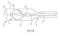
舉例來說,圖2A所示為泵殼2的內部與導管3的一遠側部分。如該示意圖所示,轉子5可以被安裝到驅動軸4的遠側部分並設置在泵殼2的內部。For example, FIG. 2A shows the interior of the
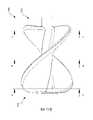
參照圖4A至圖4D,根據本發明的一個實施例更詳細地繪示出轉子5。應可理解的是,所示的轉子5為處於未壓縮或膨脹狀態;也就是靜止並且沒有外部施加的力(例如,在壓縮狀態下沒有壓縮力或在膨脹狀態下操作期間沒有壓力與旋轉力)。轉子5包括徑向可壓縮的轉子葉片17、18以及轂16。葉片17、18可以從轂16的外部徑向延伸。轂16從轉子5的近端20延伸到遠端19並且與轉子5的旋轉軸(rotational axis)30同軸地對齊。或通道(channel)29(顯示於圖4C)可以從近端20穿過轂16延伸到遠端19。泵1的驅動軸4的遠端部分,像是泵1的驅動軸4,可以延伸穿過中心孔(central bore)29以將轉子5安裝在泵1的泵殼(例如泵殼2)內並使其旋轉。Referring to FIGS. 4A to 4D , the
在一個實施例中,轉子葉片17、18可以在徑向具有彎曲的設計以及在軸向具有一彎曲的接合部(enlacement)。每個葉片17、18可以包括具有凸面的第一面(例如,吸力側)與具有凹面的第二側(例如,壓力側)。舉例來說,葉片17包括凸側(convex side)21與凹側(concave side)22,而葉片18包括凹側23與凸側24。葉片17、18可以由柔性材料製成,讓葉片17、18能夠折疊到轂16上而被壓縮至壓縮狀態。當葉片17、18被壓縮至壓縮狀態時,轉子5的徑向彎曲設計定義了轉子葉片17、18的期望或預定的壓縮或捲曲方向(也就是,每個葉片22的凹側的方向)。在此種的實施例中,在葉片21的凸側可能會發生拉伸。In one embodiment, the
再次參考圖2A,轉子5的轂16與泵殼2分別與轉子5的旋轉軸30同軸地對齊。圖2A中的泵殼2與轉子5顯示為處於未壓縮或靜止的膨脹狀態,並且不受外力影響。泵殼2與轉子5可以被徑向壓縮至壓縮狀態。在壓縮狀態下,可以使用輸送系統將泵殼2部署到患者體內。舉例來說,在一個實施例中,輸送系統可以包括導引器護套(introducer sheath),該導引器護套限制泵殼2與轉子5以將泵殼2與轉子5保持在壓縮狀態。 當被限制在導引器護套中時,泵殼2與轉子5被插入至患者體內到期望的位置。然後泵殼2可以向遠側推進,例如藉由推動導管3,使得泵殼2離開導引器護套的遠端。Referring again to FIG. 2A , the
一旦處於患者體內的期望位置,泵殼2與轉子5就會徑向膨脹至膨脹狀態。在此種實施例中,該擴張位置可以由導管3的一端定義。舉例來說,轉子5可以藉由將泵1從輸送系統(例如,導引器護套)中釋放出去而展開。在一種實施例中,泵殼2可以由形狀記憶材料製成,當泵殼2不受外部壓縮力作用時,該形狀記憶材料使泵殼2回到膨脹狀態。在另一方面,泵1可以包括用以將泵殼2膨脹至膨脹狀態的致動裝置。接著,可藉由驅動軸4旋轉轉子5以將轉子葉片17、18徑向展開至膨脹狀態。在一種實施例中,轉子5可以由不需要轉子5旋轉而使轉子5回到膨脹狀態的材料製成。Once in the desired position within the patient, the
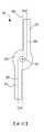
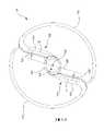
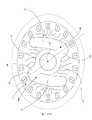
參考圖2B,在一個實施例中,泵殼2可包含由金屬網或纖維網製成的徑向可膨脹與可壓縮結構。替代地,泵殼2可包含形成一徑向可膨脹與可壓縮結構之複數個螺旋支柱。在任一情況下,軟管或密封結構(例如一聚合物膜)可以被設置在泵殼2的區域90(或區域90的至少一部分)之上以防止血液進入或流出到區域90中。在此種實施例中,膜可以產生具有液壓效能(例如用於泵送(pumping))的泵室。軟管可以由聚氨酯(polyurethane)製成並且通常為圓柱形。藉由軟管密封部分90,泵殼2的遠端部分92與近端部分94保持未密封。這樣一來,在遠端部分92形成泵殼2結構的線材或纖維之間的孔可形成泵殼2 的入口,而近端部分94的孔可形成泵殼 2的出口。在替代的實施例中,軟管或密封結構可以覆蓋和密封泵殼2的全部或至少絕大部分,並且軟管或密封結構可包括在密封結構的近端與遠端的孔,以形成泵殼2的入口和出口。Referring to Figure 2B, in one embodiment, the
在美國專利申請號 16/658,256、美國公告專利號 8,439,859,以及美國專利申請公開號 2020/0289732 A1中描述了示範性的徑向可膨脹與可壓縮的泵殼、用以膨脹與壓縮此種泵殼的結構,以及用於實施此種泵殼以與泵像是泵 1一起使用的方法,其所有內容係完整引用做為參考。Exemplary radially expandable and compressible pump casings for expanding and compressing such pumps are described in U.S. Patent Application No. 16/658,256, U.S. Publication Patent No. 8,439,859, and U.S. Patent Application Publication No. 2020/0289732 A1 The construction of the housing, and the method for implementing such a pump housing for use with a pump such as
像是轉子5的轉子葉片17、18之類的轉子葉片可以從像是轂16的轂沿著穿過轂中心並橫穿轉子的旋轉軸30之徑向軸延伸。如圖3A的轉子組態(rotor configuration)50所示,其中葉片51、52沿著徑向軸56從轂55延伸,沿著穿過轂55的中心並橫穿轉子5的旋轉軸57之徑向軸56延伸。葉片51、52在圖中所示為直的,但它們也可是彎曲的。Rotor blades, such as
根據本發明,轉子葉片17、18可以修改為從與橫穿旋轉軸的徑向軸偏移之個別軸延伸。以下會先參考圖3B至圖3D從轂延伸的平面轉子葉片的簡單情況來描述每一個設計,不過,如下所述,這些設計同樣適用於彎曲葉片,像是上述轉子5的葉片17、18。According to the invention, the
舉例來說,參考圖3B,其中所示為根據本發明處於靜止與未壓縮狀態(也就是在沒有外力的情況下)的轉子組態60。轉子組態60包括徑向可壓縮與可膨脹的轉子葉片51、52與圓柱形轂55。葉片51、52從轂55沿著相對於轂55的中心偏心或偏移徑向軸56的個別軸延伸。在圖3B的轉子組態60中,轉子葉片51沿軸58延伸,而轉子葉片52沿軸59延伸。軸58與59個別從軸56偏移一預定距離 d1並平行於軸56。轉子葉片51包括側61與62,其中側61被設置為比側62更遠離軸56。轉子葉片52包括側63與64,其中側63被設置為比側64更遠離軸56。在轉子配置60中,軸58、59與軸56之間的偏移使得葉片51的側61與葉片52的側63個別相對於轂55的圓形橫截面大致切線地延伸。應可理解的是,軸56與軸58、59之間的偏移程度,59 可能小於或大於 d1,但大於零。舉例來說,在圖3C的轉子配置70中,軸56與軸58、59之間的偏移是預定距離d2,該距離小於d1。作為另一個範例,在圖3D的轉子配置80中,軸56與軸58、59之間的偏移是預定距離d3,該距離大於d1。在轉子組態80中,軸58、59與軸56之間的偏移使得葉片51的側62與葉片52的側64個別相對於轂55的圓形橫截面大致切線地延伸。以下將更詳細地說明,轉子構造,像是組態60、70、80,其中轉子葉片從轂偏離穿過轂中心的徑向軸延伸,在泵的操作中提供了幾個優點。For example, referring to FIG. 3B, there is shown a
儘管在配置60、70、80中相對於軸56與軸58、59的偏移是使用轉子葉片51、52描述的,這些轉子葉片51、52在圖3B至圖3D中所示從轉子的轂55線性延伸。轉子組態60、70、80與上述偏移(或缺少偏移)相關的設計實施例,也會在螺旋地圍著轂纏繞的轉子葉片之內文中描述,像是轉子5的轉子葉片17、18。Although in
根據在葉片與轂的附接點相對於轂的旋轉軸正交的軸,或葉片延伸超過轂時的曲率,可以達成葉片相對於轂的橫穿或偏移。針對轉子葉片17、18從轂16延伸,轉子5係以與上述配置50類似的方式設計。如同在圖4A-圖4C中所示的最佳表示方式,其中繪示了轉子5的遠端19,葉片17、18包括區域25、26。區域25是靠近轂16設置的葉片17的一部分,而區域26是靠近轂16設置的葉片18的一部分。在一個實施例中,區域25與26 分別是葉片轉子17與18的一部分,它們直接靠近轂16 設置。如圖 4C 所示,區域25與26 沿著與轉子5的旋轉軸30正交並延伸穿過轂16的中心之徑向軸40延伸。應可理解的是,如圖4E中轉子5(圖4D)的橫截面圖所示。區域25與26(圖4C)如圖4C所示從轂沿轂的長度(也就是,從轂16的遠端19到近端20)延伸(也就是,沿徑向軸40)。在這種配置中,如圖4E中沿圖 4C的A-A、B-B,以及C-C 的橫截面所示,葉片17、18 的外部之曲率根據葉片17、18在轂16的長度上延伸的位置而變化。圖4D所示為轂上的三個位置,它們對應於三個橫截面A-A、B-B,以及C-C。如圖4E所示,在橫截面A-A處,葉片17、18的凹側22、24的內曲率比葉片凸側21、23的曲率要小(也就是,角度更小),葉片凸側21、23形成更大的角度。這在B-B橫截面中更容易觀察到。然而,在C-C橫截面中,凸側21、23的凸曲率與凹側22、24的凹曲率大致互補。因此,在圖4A至4E所示的實施例中,葉片17、18的每個外部的螺距沿轂16的長度變化。Traversing or offsetting of the blade relative to the hub may be achieved according to an axis orthogonal to the axis of rotation of the hub at the point of attachment of the blade to the hub, or the curvature of the blade as it extends beyond the hub. The
在一個實施例中,轉子5可以被修改為,類似於以上關於組態60、70、80描述的葉片偏移,每個葉片17與18中的至少一部分,像是區域25與26,從轂16沿著個別軸或多條軸相對於徑向軸40偏移。In one embodiment, the
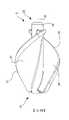
舉例來說,參考圖5A至圖5D,其中所示為本發明的另一實施例之轉子105。應可理解的是,轉子105顯示為處於未壓縮或膨脹狀態並且處於靜止以及沒有外部施加的力(例如,在壓縮狀態下沒有壓縮力並且在膨脹狀態下操作期間沒有壓力與旋轉力)。轉子105包括徑向可壓縮的轉子葉片117、118,以及轂116。葉片117、118從轂116的外部徑向延伸。轂116從轉子105的近端120延伸到遠端119並且與轉子的旋轉軸同軸地對齊。中心孔或通道129(如圖5C所示)從端部120延伸穿過轂116到端部119。泵的驅動軸的遠端部分,像是泵1的驅動軸4,可以延伸穿過中心孔129以在泵的泵殼,像是泵殼2內,支撐與旋轉轉子105。以下將更詳細描述,轉子105可以模製在驅動軸4的遠端部分上。For example, referring to FIG. 5A to FIG. 5D , there is shown a
在一個實施例中,轂116是圓柱形的並且包括從端部119到端部120的恆定直徑。然而,如以下所述,在一些實施例中,轂116的直徑可以從一端到另一端逐漸變細。In one embodiment,
在一個實施例中,轉子葉片117、118可以在徑向具有彎曲的設計並且在軸向具有彎曲的接合部。每個葉片117、118可以包括具有凸面的第一側(例如,吸力側)與具有凹面的第二側(例如,壓力側)。舉例來說,葉片117可以包括凸側121與凹側122,並且葉片118包括凸側123與凹側124。葉片117、118藉由柔性材料附接至轂116,使得葉片117、118在被壓縮到壓縮狀態時是可折疊在轂116上的。在壓縮狀態下,凹側122、124 更靠近或甚至靠在轂116的外部。在給定葉片曲率時,每個葉片117、118可以至少部分地圍繞轂116。轉子105的徑向彎曲設計在葉片117、118被壓縮到壓縮狀態時,定義轉子葉片117、118的較佳壓縮或捲曲方向(也就是每個葉片的凹側的方向)。In one embodiment, the
在一個實施例中,每個葉片117、118包括恆定的螺距,然而,如下所述,在其他實施例中,葉片117、118可以個別包括可變的螺距。In one embodiment, each
如圖5A-圖5C所示的最佳方式,其中顯示了轉子105的遠端119,葉片117、118可包括內部區域125、126。區域125是葉片117從轂116向葉片117的外部邊緣延伸的部分,區域126是葉片118從轂116向葉片118的外部邊緣延伸的區域。在一個實施例中,區域125與126分別是葉片117與118的區域,它們直接靠近轂設置,並且在每個葉片117、118的外部邊緣之前終止。在另一實施例中,區域125、126分別從轂116延伸到葉片117、118的外部邊緣之整個距離。In the best mode shown in FIGS. 5A-5C , where the
如圖5C所示,區域125沿軸141延伸,區域126沿軸142延伸。軸141、142相對於轂116的中心偏移。此外,軸141、142個別相對於徑向軸140偏離一預定距離d並實質上與徑向軸140平行。在描述軸141、142相對於徑向軸140的關係的內容中,「實質上平行(substantially parallel)」是指每個軸141、142與徑向軸140之間的預定距離d在每個區域125、126中的整個長度上大致相同或恆定。換句話說,即使每個軸141、142相對於徑向軸140略微傾斜(例如,1°到20°),出於描述本發明的目的,軸141、142仍可被認為與徑向軸140「實質上平行」。As shown in FIG. 5C ,
徑向軸140延伸穿過旋轉軸130並且正交地橫穿旋轉軸130。應可理解的是,如圖5E中轉子105的橫截面圖所示(其為沿轂116的不同位置截取的轉子105之橫截面),在一個實施例中,軸141、142相對於徑向軸140的偏移從轂116的遠端119持續到近端120(圖5D)。換句話說,在沿轂116軸向的任何點,區域125、126可以從轂116以距徑向軸140的預定偏移距離d延伸。如下所述,在其他實施例中,軸141、142之間相對於徑向軸140的偏移可以僅沿著轂的一些部分(例如,在轉子105的近端、遠端以及/或者中心部分)。此外,在一些實施例中,偏移的預定距離d可以在沿著轉子105的軸向長度的不同位置變化。The
再次參考圖5C,在一個實施例中,葉片117的區域125在葉片117的凸側121的方向上從軸140偏移,而葉片118的區域126在葉片118的凸側123的方向上從軸140偏移。以此方式,區域125、126完全偏移到軸140的相對側。在一個實施例中,偏移的預定距離d係選擇為使得區域125的凸側121的表面從轂116的外圓周實質上切線地(也就是說,大致沿著切線)延伸,並且區域126的凸側123的表面從轂116的外圓周實質上切線地延伸。此外,預定距離d係選擇為使得,在區域125,凹側122在凸側121的方向上從軸140偏移或隔開,以及,在區域126,凹側124在凸側123的方向上從軸140偏移或隔開。換句話說,每個側面121、122、123、124相對於轂116的中心偏心並且偏移軸140。Referring again to FIG. 5C , in one embodiment,
如上所述,轉子105的每個區域125、126的偏移位置可以提供相對於轉子,像是不包括這種偏移的轉子5與轉子組態50,一些沒有的優點。As noted above, the offset position of each
舉例來說,參考圖6A與6B,圖6A所示為處於壓縮狀態的轉子5,而圖6B所示為處於壓縮狀態的轉子105。如圖6A所示,在壓縮狀態下,轉子葉片17、18被折疊到轂16上。然而,葉片17、18在折疊中會產生對應的尖銳扭結(kink)601、602。扭結601、602可能出現在轉子5中,因為葉片17、18的區域25與26從轂16沿徑向軸 40 延伸,因此不會阻止轉子葉片17、18 彎曲回到轂 16。這樣一來,葉片 17、18 更可能以與轂16 徑向間隔開的銳角屈折或彎曲,並因此形成扭結 601、602。這種扭結可能對轉子葉片17、18與轂16施加應力與應變,並增加葉片 17、18 無法恢復到原來的未壓縮、膨脹狀態而永久變形的可能。For example, referring to FIGS. 6A and 6B , FIG. 6A shows the
轉子葉片117、118的偏移設計避免了轉子5的轉子葉片17、18產生尖銳扭結。舉例來說,如圖6B所示,在壓縮狀態下,轉子葉片117、118的區域125、126相對於徑向軸140的偏移允許葉片117、118至少部分地圍著轂116纏繞,符合轂曲率。因此,圖6A所示的轉子5在壓縮狀態下發生的尖銳扭結在圖6B所示的壓縮轉子中不復存在。由於區域125、126 相對於轂 116 的偏心位置,在每個葉片 117、118的凹側 122、124 上有更多空間,使得葉片 117、118 可以更平滑地圍繞轂 116,使得凹側122、124在壓縮狀態下更均勻地靠在轂116上,以減輕每個葉片117、118中的扭結。由於葉片117、118更均勻地靠在轂116上,所以當壓縮時,作用在葉片117、118上的力傳遞到轂116外徑上的扭矩,藉此減少或消除葉片117、118在壓縮時的扭結。以此方式,葉片117、118的偏移位置減少了處於壓縮狀態的葉片117、118上的應力以及可能由於此種應力導致的葉片變形。在壓縮狀態下葉片117、118上的應力減少進一步允許葉片117、118展開到它們在未壓縮、膨脹狀態下的自然位置,這是因為葉片117、118由於壓縮狀態下的葉片應力而使得永久變形的可能性降低。此外,這也使得減壓後的轉子105的形狀比轉子5的形狀更一致。The offset design of the
減輕葉片117、118 在壓縮狀態下的尖銳扭結可以減少並且還減輕在轉子葉片 117、118 附接至轂116的區域時轂116上的應力與應變。這可以允許轂116的厚度與總直徑相對於轉子5的轂16減少,因為不需要更厚的轂來承受更大的應力。Alleviating sharp kinks of the
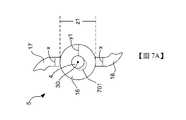
舉例來說,參考圖7A,轉子5的轂16可以具有直徑z1與厚度y1。每個轉子葉片17、18包括厚度x。根據在轉子5被壓縮時以及/或者在轉子5旋轉期間轂16上的應力,厚度y1被選擇為足夠大以防止轂16的內徑從泵1的驅動軸4分層(delamination)。分層可能發生在轂16上的拉應力最高的地方。轂16的示範性分層在圖7A中由附圖標記701表示。應可理解的是,轂16的厚度y1大於每個葉片轉子17、18的厚度x。For example, referring to FIG. 7A , the
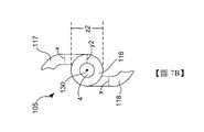
參考圖7B,轉子105的設計可以減少轂116上的應力。因此,轂116的厚度y2被選擇為小於轂16的厚度y1而不減少轉子葉片117的厚度x,以防止轂116從驅動軸4分層。在一個實施例中,轂116的厚度y2可以是轂16的厚度y1的50%。因此,轂116的直徑z2小於轂16的直徑z1。此外,在一個實施例中,轂116的厚度y2大約(例如+/-10%)等於轉子葉片117、118的厚度x。轂116的直徑z2減少並且防止轉子葉片117、118在壓縮狀態下扭結,降低了轉子105相對於轉子5在壓縮狀態下的總直徑,這也減少了泵殼2在壓縮狀態下的直徑。因此,當轉子105與泵1一起使用時,處於壓縮狀態的泵殼2的直徑減少可以允許在將泵植入或插入患者體內時所用的動脈切開術切口縮小。此外,當使用轉子105時,施加在轉子105與泵殼2的內塗層上的回彈力可以減少,如此一來可降低將轉子105部署到患者體內/從患者體內取出轉子的插入力與移除力。舉例來說,轉子105的設計使得轉子葉片在壓縮狀態下的向外徑向力相對於轉子5減少。因此,由於在壓縮狀態下轉子葉片 117、118 的向外徑向力減少,在壓縮狀態下,轉子105可以更容易地滑動通過輸送系統的組件(例如,導引器護套)。Referring to FIG. 7B , the
應可理解的是,因為轉子105的直徑z2小於轉子5的直徑z1,所以葉片117、118可以從轂116延伸更長的徑向距離(與葉片17、18從轂16延伸的距離相比),同時仍然允許轉子5與105在使用期間具有相同的膨脹轉子直徑(當轉子5、105在旋轉時)。以此方式,儘管在使用過程中具有相同的膨脹轉子直徑,轉子葉片117、118相對於轉子葉片17、18的較大徑向長度讓轉子105相對於轉子5在血流方面更有效。It will be appreciated that because the diameter z2 of the
應可理解的是,在轉子105與泵1一起使用的期間,轉子105呈現出除了完全壓縮組態與未壓縮或膨脹組態(當轉子105靜止時)之外的其他組態。舉例來說,當轉子105在使用期間旋轉時,由於離心力與轉子105輸送的流體的壓力,轉子105的直徑從其自然未壓縮與膨脹組態擴張,超過轉子105的直徑。此外,當離心力與其他壓力施加在葉片117、118上時,每個葉片117、118中的曲率減少或變平。這些進一步的配置端視轉子105的圓周速度(也就是,旋轉速度)。與轉子105從壓縮組態到自然膨脹組態(也就是,沒有應力與應變施加在轉子上)的變形相比,在運作期間轉子上所承受的附加應力與應變時所造成的轉子變形較小。在一個實施例中,轉子105的形狀和尺寸被設計成使得在使用期間當轉子受到在此所述的作用力時,轉子發生的任何變形,都得到控制、最小化或消除。It will be appreciated that during use of the
避免葉片117、118在壓縮狀態下的尖銳扭結減少了施加到轉子105的材料上的最大應變。因此,轉子105的偏移設計允許使用比可用於轉子 5的材料更廣泛的材料。可與轉子 105 一起使用的材料變得更廣泛可以提高轉子105 的可製造性。舉例來說,在壓縮期間轉子 5 的材料上之極端應變(例如,高達100%的局部應變)需要使用的非常抗應力材料,例如聚氨酯,它具有高水平的交聯度(level of crosslinking)。相形之下,由於採用偏移設計,轉子 105 上減少的應變(例如,高達 70% 的局部應變)有助於拓展用於模製轉子105的可用材料選擇。應可理解的是,本文所述的局部應變(local strain)指的是相對於中性纖維(也就是凸面與凹面之間每個葉片的中線),每個轉子葉片(即每個葉片的凸面)的彎曲外曲率拉伸。舉例來說,在一些實施例中,該外曲率在每個轉子葉片(例如,凸面側)可以是180°。由於在轉子105的設計中(與轉子5相比),將彎曲程度(當葉片被折疊時)不同地設定,與轉子葉片上的局部應力相比,轉子105中的轉子葉片117、118上的局部應力比轉子5的轉子葉片17、18上的局部應力要小。Avoiding sharp kinks of the
舉例來說,偏移設計允許使用熱塑性聚氨酯,其交聯量比用於轉子 5 的聚氨酯低。用於模製轉子105 的材料具有較低的交聯量使得射出成型製造技術可以用來製造轉子105,這使得大量生產更具成本效益。這也可以適用在保證鑄模、真空成型,以及/或者消失模的情況。For example, the offset design allows the use of thermoplastic polyurethane, which has a lower amount of crosslinking than the polyurethane used for
在一個實施例中,轉子105係被模製在驅動軸4上作為具有高彈性與低滯後性(low hysteresis)的單件彈性體。舉例來說,轉子可以由熱塑性彈性體(TPE)形成,例如聚酰胺TPE (TPA)、共聚酯TPE (TPC)、苯乙烯TPE (TPS)、聚氨酯TPE (TPU)、與 TPE交聯的橡膠 (TPV) 或丙烯腈/丁二烯橡膠+聚氯乙烯 (TPZ)。 作為另一範例,轉子可以由聚烯烴彈性體(TPO)或熱塑性聚酰胺彈性體形成。其他以這種方式製造與模製轉子105的示範性材料已於美國公告專利號10,584,589中進行描述,在此並引用其所有內容做為參考。In one embodiment, the
應可理解的是,當轉子5、105在膨脹狀態下的相同最大直徑與相同轉速下,轉子105的設計相對於轉子5具有改進的流速(以升/分鐘計的更高流量)。 如上述,流速改進的一種解釋可能是轉子葉片117、118的徑向長度相對於轉子葉片17、18的長度而言相對較大,這是由於轂116的直徑相對於轂16有減少的關係。It will be appreciated that the design of the
此外,在轉子5、105的相同最大直徑與相同轉速下,與轉子5相比,轉子105的設計可以減輕血液流過轉子時對血液的溶血和其他損傷。 在一些實施例中,即使在比轉子5的轉速更高的轉速下,使用轉子105也減輕了溶血。在施加相同應力的情況下,可能發生相同量的溶血。由於轉子105的設計相對於轉子5產生了更高的流量,因此可以減少單位體積的損傷。此外,由於轉子105的設計相對於轉子5產生更高的流速,血液承受由轉子引起的應力之時間長度可以減少。與較長的衝擊持續時間相比,血細胞更能承受短時間的壓力。In addition, under the same maximum diameter and the same rotational speed of the
還應了解的是,當轉子105與泵1 一起使用時,流動特性(例如,由泵 1 輸送的血液)與馬達電流(例如,在使用泵1的期間馬達 6的電流)之間,還有液壓對馬達電流之間的關係都分別獲得改善。此種改進可以使得控制馬達6的泵控制器之馬達電流訊號連同轉子105的旋轉速度可用於即時計算由泵1輸送的血液流量,而無需額外的感測器。應可理解的是,這種計算可以由圖1中所示的控制馬達6的泵控制器31或本發明的泵系統的其他處理器或控制器來執行。這樣一來,控制器或處理器(例如,泵控制器31)可以根據使用馬達電流訊號與轉子105的旋轉速度來計算,藉此維持期望的流量。It should also be appreciated that when the
舉例來說,參考圖8,其中所示為本發明包括曲線的圖表,該曲線將馬達電流與在不同轉子速度下使用轉子5的泵1之流量進行比較。圖8中的曲線顯示一個平坦或反斜率(counter slope)。由於圖8中的幾條曲線具有相同的馬達電流,因此在沒有進一步資訊的情況下無法計算使用轉子 5 時泵1的流量。For example, reference is made to Fig. 8, which shows a graph of the present invention including curves comparing motor current and flow for a
參考圖9,其中所示為本發明包括曲線的圖表,該曲線將馬達電流與在不同轉子速度下使用轉子105的泵1之流量進行比較。圖9中的曲線顯示,當泵1使用轉子105 時,馬達電流與流量之間存在很強烈的單調關係。因此,當泵1使用轉子 105 時,在沒有進一步資訊的情況下,也可以根據馬達6的馬達電流計算流量(例如,藉由控制器控制馬達6或系統的另一個處理器)。Referring to Figure 9, there is shown a graph of the present invention including curves comparing motor current to flow rate for
應可理解的是,圖8與圖9中從底部到頂部的曲線對應於測試期間使用的以下轉子速度:15 krpm(每分鐘千轉)、18 krpm、20 krpm、22 krpm、24 krpm、26 krpm、28 krpm、30 krpm,以及32 krpm。應可理解的是,1000 rpm 相當於 1 krpm。It should be understood that the curves from bottom to top in Figures 8 and 9 correspond to the following rotor speeds used during testing: 15 krpm (thousand revolutions per minute), 18 krpm, 20 krpm, 22 krpm, 24 krpm, 26 krpm, 28 krpm, 30 krpm, and 32 krpm. It should be understood that 1000 rpm is equivalent to 1 krpm.
比較圖8與圖9,上述關於轉子105相對於轉子5的操作之改進可以參考圖8與圖9中關於流量與馬達電流之間的關係。在這方面,圖 9 中的流量與馬達電流之間的關係比圖 8 中所示的關係更線性。整體來說,流量差異(在給定壓力下)對轉子105的馬達電流與轉子5相比,具有較少的變動影響。這顯示流過轉子105 的血液比流過轉子 5 的血液較少動盪。Comparing FIG. 8 and FIG. 9 , the above-mentioned improvements regarding the operation of the
在一個實施例中,每個葉片117、118都包括在每個葉片的長度上之單調錐度(拔模角(draft angle))以改進射出成型轉子105的脫模。該拔模角可以是軸向以及/或者徑向的,視模具設計(mold-design)而定。In one embodiment, each
應可理解的是,如上所述,在一個實施例中,葉片117、118的區域125、126在轂116的整個軸向長度上相對於軸140偏移(如圖5E所示)。在其他實施例中,葉片117、118的區域125、126可以僅在沿軸130軸向的選定點或部分相對於軸140(與旋轉軸130正交)偏移。舉例來說,在一個實施例中,葉片117在區域125的遠端部分與葉片118在區域126的遠端部分可以從軸140偏移預定距離,但是區域125、126的其餘部分沿徑向軸140延伸並且不包括偏移。在另一實施例中,葉片117在區域125的近端部分與葉片118在區域126的近端部分可以從軸140偏移預定距離,但是區域125、126的其餘部分沿徑向軸140延伸並且不包括偏移。在另一實施例中,轉子105的遠端119與近端120之間的每個區域125、126的中心部分可以從軸140偏移預定距離,但是區域125、126的遠端與近端部分可不包括一個偏移量。在另一實施例中,區域125、126可以在轂116的整個軸向長度上偏移,但是葉片117、118的區域125、126與徑向軸之間的偏移距離可以沿著轂116的長度變化。如上所述,在一個實施例中,葉片117、118可包括恆定的螺距。恆定的螺距可以允許在製造期間更容易地將轉子105脫模。在其他實施例中,轉子葉片117、118的螺距可以根據需要改變。此外,轉子葉片117、118可以根據需要包括圍繞轂116的四分之一扭轉、二分之一扭轉,或盡可能多的多重扭轉(或其一部分)。此外,儘管上面關於轉子105係以兩個轉子葉片117、118圖示與敘述,但是轉子105可以包括單個轉子葉片或任意數量的轉子葉片,而不悖離本說明書所述的內容。以此方式,轉子105的葉片在尺寸、形狀和螺距上可以變化,因此可以用於各種應用。It should be appreciated that, as noted above, in one embodiment the
在一個實施例中,從轂116到每個葉片117、118的邊緣之徑向距離可以從轉子105的一端到轉子105的另一端以錐形方式變化。錐度可以是恆定的或沿轂的長度變化。應可理解的是,轉子105的三維形狀可以相對於圖中所示與在此描述的進行修改,以改進使用轉子105的泵的效能之各種實施例。泵效能的此些實施例可以包括但不限於提高效率、提升承受壓力、更好的流量與壓差關係,或根據轉子105的形狀而受到影響的泵效能之任何其他實施例。In one embodiment, the radial distance from the
儘管上述將轂116描述為沿轂116的長度具有恆定直徑的圓柱形,但在其他實施例,轂116可具有圓錐或截頭圓錐形狀(frustoconical)(也就是,截頭圓錐體),使得轂116是錐形的。在轂116具有截頭圓錐形狀的情況下,轂116在一端包括比在相對端的直徑更大的直徑。舉例來說,參考圖10,所示的轂 116 在遠端119的直徑「b」小於轂116的近端120的直徑「c」。在一個實施例中,轂116在轂116的長度上可以是單調形成的。錐形轂可以使轉子105更容易脫模。Although the
應可理解的是,如上所述,葉片117、118的區域125、126之間相對於軸140的偏移程度可以在沿轂116的不同軸向位置處變化。沿轂 116 軸向偏移的程度可能受到轂116的錐度/圓柱度的影響。舉例來說,當轉子 105 包括一個在轂116的長度上具有恆定直徑的圓柱形轂116時,轉子葉片117、118的每個區域125、126與軸140的偏移程度可以不沿轂116的長度變化。然而,當轉子105包括錐形轂116的情況下,如圖10所示,葉片117、118的每個區域125、126相對於軸140的偏移距離d可以從轂116的一端到轂116的另一端變化。舉例來說,偏移距離d將隨著轂116的直徑減少而增加,並且偏移距離d將隨著轂116的直徑增加而減少。在一種實施例中,在轂116的中心軸向位置,偏移可以類似於上述關於圖3B描述的轉子配置60,朝向轂116的端部119,其中轂116的直徑相對較小,偏移可以類似於上述關於圖3D描述的轉子組態80,並且朝向轂116的端部120,其中轂116的直徑相對較大,偏移可以類似於上述關於圖3C描述的轉子組態70。It will be appreciated that the degree of offset between the
應可理解的是,雖然以上描述的轉子105係與包括柔性驅動軸4與外部馬達6(位於患者體外)的泵1一起使用,但是轉子105可以與任何其他類型的流體泵一起使用以輸送流體。舉例來說,轉子105可以佈置在泵,像是血泵,的泵殼體中,該泵包括安裝轉子105的剛性(非柔性)驅動軸。該泵可以包括用於驅動剛性驅動軸的機載馬達,其中馬達位於泵殼中或靠近泵殼附近(例如在泵殼的近端)。It should be appreciated that although the
從前述內容並參考各種附圖,熟悉此技藝者應可理解在不悖離本發明的範圍的情況下可以對本發明進行某些修改。儘管在附圖中已經繪示了本發明的若干實施例,但並不意欲將本發明限制於此,本發明的範疇應與本技術領域所允許的一樣寬廣,並且應以同樣地的設想閱讀本說明書。因此,以上描述不應被解釋為限制性的,而僅為特定實施例的範例。熟悉此技藝者應可設想在所附申請專利範圍的範疇與精神內進行其他修改。From the foregoing, and with reference to the various drawings, it will be apparent to those skilled in the art that certain modifications may be made to the invention without departing from the scope of the invention. Although several embodiments of the invention have been illustrated in the drawings, it is not intended to limit the invention thereto, but the scope of the invention should be as broad as the art will allow and should be read in the same light. this manual. Accordingly, the above description should not be construed as limiting, but merely exemplifications of particular embodiments. Those skilled in the art should be able to imagine other modifications within the scope and spirit of the appended claims.
1:泵 2:泵殼 3:導管 4:驅動軸 5:轉子 6:馬達 7:埠 8:股動脈 9:主動脈弓 10:心室 11:近端 12:箭頭 13:遠端 14:開口 15:開口 16:轂 17:轉子葉片 18:轉子葉片 19:端部 20:端部 21:凸側 22:凹側 23:凹側 24:凸側 25:區域 26:區域 29:中心孔 30:旋轉軸 31:控制器 40:徑向軸 50:轉子組態 51:葉片 52:葉片 55:轂 56:徑向軸 57:旋轉軸 58:軸 59:軸 60:轉子組態 61:側 62:側 63:側 64:側 70:轉子組態 80:轉子組態 90:區域 92:遠端部分 94:近端部分 105:轉子 116:轂 117:轉子葉片 118:轉子葉片 119:遠端 120:近端 121:凸側 122:凹側 123:凸側 124:凹側 125:區域 126:區域 129:中心孔 130:旋轉軸 140:徑向軸 141:軸 142:軸 601:扭結 602:扭結 701:分層 b:直徑 c:直徑 d:預定距離 d1:預定距離 d2:預定距離 d3:預定距離 A-A:橫截面 B-B:橫截面 C-C:橫截面 x:厚度 y1:厚度 y2:厚度 z1:直徑 z2:直徑1: pump 2: pump casing 3: Conduit 4: drive shaft 5: rotor 6: Motor 7: port 8: Femoral artery 9: Aortic arch 10: ventricle 11: near end 12: Arrow 13: remote 14: opening 15: opening 16: hub 17: Rotor blade 18: Rotor blade 19: end 20: end 21: convex side 22: concave side 23: concave side 24: convex side 25: area 26: area 29: Center hole 30: axis of rotation 31: Controller 40: Radial shaft 50: Rotor configuration 51: blade 52: blade 55: hub 56: Radial shaft 57: axis of rotation 58: axis 59: axis 60: Rotor configuration 61: side 62: side 63: side 64: side 70: Rotor configuration 80: Rotor configuration 90: area 92: Distal part 94: Proximal part 105: rotor 116: hub 117: rotor blade 118: rotor blade 119: remote 120: near end 121: convex side 122: concave side 123: convex side 124: concave side 125: area 126: area 129: Center hole 130: axis of rotation 140: Radial shaft 141: axis 142: axis 601: kink 602: kink 701: layered b: diameter c: diameter d: predetermined distance d1: predetermined distance d2: predetermined distance d3: predetermined distance A-A: cross section B-B: cross section C-C: cross section x: thickness y1: thickness y2: thickness z1: diameter z2: diameter
圖1所示為本發明的一泵系統; 圖2A所示為本發明的圖1的泵的遠端部分之局部側視圖; 圖2B所示為本發明與圖1的泵一起使用的示範性泵殼結構; 圖3A所示為一先前技術的轉子結構; 圖3B至圖3D所示為本發明的各種轉子結構; 圖4A至圖4D所示為本發明的處於未壓縮或膨脹狀態並且靜止的可壓縮與可膨脹轉子之各種示意圖; 圖4E所示為本發明沿著圖4D中所示的截面A-A、B-B,以及C-C的包括圖1與圖2的可壓縮與可膨脹轉子之橫截面圖; 圖5A至圖5D所示為本發明的另一處於未壓縮或膨脹狀態並且靜止的可壓縮與可膨脹轉子之各種示意圖; 圖5E所示為本發明沿著圖5D中所示的截面A-A、B-B,以及C-C的可壓縮與可膨脹轉子之橫截面圖; 圖6A所示為本發明的圖4A至圖4D的處於壓縮狀態的轉子之示意圖; 圖6B所示為本發明的圖5A至圖5D的處於壓縮狀態的轉子之示意圖; 圖7A所示為本發明的圖4A至圖4D的轉子之局部示意圖; 圖7B所示為本發明的圖5A至圖5D的轉子之局部示意圖; 圖8所示為使用本發明的圖4A至圖4D的轉子之圖1的泵的操作特性之圖表; 圖9所示為使用本發明的圖5A至圖5D的轉子之圖1的泵的操作特性之圖表;以及 圖10所示為使用本發明的處於未壓縮或膨脹狀態且靜止的可壓縮與可膨脹轉子之側視圖,包括錐形轂。Fig. 1 shows a pump system of the present invention; Figure 2A shows a partial side view of the distal portion of the pump of Figure 1 of the present invention; Figure 2B shows an exemplary pump casing configuration for use with the pump of Figure 1 according to the present invention; Figure 3A shows a prior art rotor structure; 3B to 3D show various rotor structures of the present invention; Figures 4A to 4D show various schematic views of the compressible and expandable rotors of the present invention in an uncompressed or expanded state and at rest; Figure 4E is a cross-sectional view of the present invention including the compressible and expandable rotors of Figures 1 and 2 along sections A-A, B-B, and C-C shown in Figure 4D; Figures 5A to 5D show various schematic views of another compressible and expandable rotor at rest in an uncompressed or expanded state; Figure 5E is a cross-sectional view of the compressible and expandable rotors of the present invention along sections A-A, B-B, and C-C shown in Figure 5D; FIG. 6A is a schematic diagram of the rotor in a compressed state of FIGS. 4A to 4D of the present invention; FIG. 6B is a schematic diagram of the rotor in a compressed state of FIG. 5A to FIG. 5D of the present invention; Figure 7A is a partial schematic view of the rotor of Figures 4A to 4D of the present invention; Figure 7B is a partial schematic view of the rotor of Figures 5A to 5D of the present invention; Figure 8 is a graph showing the operating characteristics of the pump of Figure 1 using the rotor of Figures 4A-4D of the present invention; Figure 9 is a graph showing the operating characteristics of the pump of Figure 1 using the rotor of Figures 5A-5D of the present invention; and Figure 10 is a side view of a compressible and expandable rotor at rest in either an uncompressed or expanded state, including a tapered hub, using the present invention.
1:泵1: pump
2:泵殼2: pump casing
3:導管3: Conduit
4:驅動軸4: drive shaft
5:轉子5: rotor
6:馬達6: Motor
7:埠7: port
8:股動脈8: Femoral artery
9:主動脈弓9: Aortic arch
10:心室10: ventricle
11:近端11: near end
12:箭頭12: Arrow
13:遠端13: remote
14:開口14: opening
15:開口15: opening
31:控制器31: Controller
Claims (28)
Translated fromChineseApplications Claiming Priority (2)
| Application Number | Priority Date | Filing Date | Title |
|---|---|---|---|
| US202163159665P | 2021-03-11 | 2021-03-11 | |
| US63/159,665 | 2021-03-11 |
Publications (1)
| Publication Number | Publication Date |
|---|---|
| TW202241538Atrue TW202241538A (en) | 2022-11-01 |
Family
ID=80819954
Family Applications (1)
| Application Number | Title | Priority Date | Filing Date |
|---|---|---|---|
| TW111108531ATW202241538A (en) | 2021-03-11 | 2022-03-09 | Pump including a compressible rotor having offset rotor blades |
Country Status (11)
| Country | Link |
|---|---|
| US (1) | US12343519B2 (en) |
| EP (1) | EP4281171A1 (en) |
| JP (1) | JP2024509249A (en) |
| KR (1) | KR20230156379A (en) |
| CN (1) | CN117083101A (en) |
| AU (1) | AU2022232724A1 (en) |
| CA (1) | CA3210292A1 (en) |
| DE (1) | DE112022001482T5 (en) |
| IL (1) | IL305501A (en) |
| TW (1) | TW202241538A (en) |
| WO (1) | WO2022189585A1 (en) |
Families Citing this family (2)
| Publication number | Priority date | Publication date | Assignee | Title |
|---|---|---|---|---|
| US12257426B2 (en)* | 2022-12-02 | 2025-03-25 | Abiomed Europe Gmbh | Compressible rotor |
| WO2024250015A2 (en)* | 2023-06-02 | 2024-12-05 | Georgia Tech Research Corporation | Centrifugal lvad with wireless power transfer and antithrombotic slic coating |
Family Cites Families (10)
| Publication number | Priority date | Publication date | Assignee | Title |
|---|---|---|---|---|
| US4919647A (en) | 1988-10-13 | 1990-04-24 | Kensey Nash Corporation | Aortically located blood pumping catheter and method of use |
| US8439859B2 (en) | 2007-10-08 | 2013-05-14 | Ais Gmbh Aachen Innovative Solutions | Catheter device |
| EP2218469B1 (en)* | 2009-02-12 | 2012-10-31 | ECP Entwicklungsgesellschaft mbH | Casing for a functional element |
| EP2407185A1 (en)* | 2010-07-15 | 2012-01-18 | ECP Entwicklungsgesellschaft mbH | Radial compressible and expandable rotor for a pump with a turbine blade |
| EP2407186A1 (en) | 2010-07-15 | 2012-01-18 | ECP Entwicklungsgesellschaft mbH | Rotor for a pump, produced with an initial elastic material |
| EP2407187A3 (en) | 2010-07-15 | 2012-06-20 | ECP Entwicklungsgesellschaft mbH | Blood pump for invasive application within the body of a patient |
| EP2868331B1 (en) | 2013-11-01 | 2016-07-13 | ECP Entwicklungsgesellschaft mbH | Pump, in particular blood pump |
| US9726195B2 (en)* | 2015-03-25 | 2017-08-08 | Renzo Cecere | Axial flow blood pump |
| EP3088017A1 (en) | 2015-04-30 | 2016-11-02 | ECP Entwicklungsgesellschaft mbH | Rotor for a fluid pump and method and mould for its preparation |
| CA3066361A1 (en)* | 2017-06-07 | 2018-12-13 | Shifamed Holdings, Llc | Intravascular fluid movement devices, systems, and methods of use |
- 2022
- 2022-03-09TWTW111108531Apatent/TW202241538A/enunknown
- 2022-03-10KRKR1020237034488Apatent/KR20230156379A/enactivePending
- 2022-03-10CNCN202280020401.6Apatent/CN117083101A/enactivePending
- 2022-03-10DEDE112022001482.2Tpatent/DE112022001482T5/enactivePending
- 2022-03-10WOPCT/EP2022/056244patent/WO2022189585A1/ennot_activeCeased
- 2022-03-10EPEP22711557.3Apatent/EP4281171A1/enactivePending
- 2022-03-10USUS17/691,635patent/US12343519B2/enactiveActive
- 2022-03-10AUAU2022232724Apatent/AU2022232724A1/enactivePending
- 2022-03-10CACA3210292Apatent/CA3210292A1/enactivePending
- 2022-03-10JPJP2023554868Apatent/JP2024509249A/enactivePending
- 2022-03-10ILIL305501Apatent/IL305501A/enunknown
Also Published As
| Publication number | Publication date |
|---|---|
| IL305501A (en) | 2023-10-01 |
| KR20230156379A (en) | 2023-11-14 |
| DE112022001482T5 (en) | 2024-03-28 |
| CN117083101A (en) | 2023-11-17 |
| JP2024509249A (en) | 2024-02-29 |
| US20220288381A1 (en) | 2022-09-15 |
| WO2022189585A1 (en) | 2022-09-15 |
| CA3210292A1 (en) | 2022-09-15 |
| EP4281171A1 (en) | 2023-11-29 |
| AU2022232724A1 (en) | 2023-09-21 |
| US12343519B2 (en) | 2025-07-01 |
Similar Documents
| Publication | Publication Date | Title |
|---|---|---|
| US12420076B2 (en) | Intravascular blood pump with outflow hose | |
| US20240328427A1 (en) | Radially compressible and expandable rotor for a pump having an impeller blade | |
| CN103975165B (en) | The pump casing, inside which the pump rotor can be accommodated | |
| JP7693690B2 (en) | Intravascular blood pump with intake filter | |
| JP7150617B2 (en) | impeller and blood pump | |
| US8979493B2 (en) | Fluid pump | |
| TW202241538A (en) | Pump including a compressible rotor having offset rotor blades | |
| CN105833369B (en) | Pump rotor made of a first elastic material | |
| WO2017137604A1 (en) | Blood pump | |
| CN120053873A (en) | Blood pump | |
| CN119607400A (en) | Interventional blood pump | |
| HK1199915B (en) | Pump housing with an interior for accomodating a pump rotor | |
| HK1235326A1 (en) | A fluid pump having a pump housing having an interior for accommodating a pump rotor | |
| HK1235326A (en) | A fluid pump having a pump housing having an interior for accommodating a pump rotor | |
| HK1223867A1 (en) | Pump, in particular a blood pump |