TW202239547A - Robot control device, robot control system, and robot control method - Google Patents
Robot control device, robot control system, and robot control methodDownload PDFInfo
- Publication number
- TW202239547A TW202239547ATW111108411ATW111108411ATW202239547ATW 202239547 ATW202239547 ATW 202239547ATW 111108411 ATW111108411 ATW 111108411ATW 111108411 ATW111108411 ATW 111108411ATW 202239547 ATW202239547 ATW 202239547A
- Authority
- TW
- Taiwan
- Prior art keywords
- robot
- aforementioned
- current position
- control device
- programmable logic
- Prior art date
Links
- 238000000034methodMethods0.000titleclaimsdescription18
- 238000012546transferMethods0.000abstractdescription17
- 238000012790confirmationMethods0.000abstractdescription15
- 238000010586diagramMethods0.000description10
- 230000007246mechanismEffects0.000description10
- 238000001514detection methodMethods0.000description9
- 230000008569processEffects0.000description6
- 230000006870functionEffects0.000description5
- 238000012545processingMethods0.000description5
- 239000004973liquid crystal related substanceSubstances0.000description4
- 230000008859changeEffects0.000description3
- 230000002093peripheral effectEffects0.000description3
- 230000009471actionEffects0.000description2
- 238000004364calculation methodMethods0.000description2
- 238000003825pressingMethods0.000description2
- 238000004088simulationMethods0.000description2
- 238000003466weldingMethods0.000description2
- 239000012636effectorSubstances0.000description1
- 230000000694effectsEffects0.000description1
- 230000008676importEffects0.000description1
- 238000012905input functionMethods0.000description1
- 230000003287optical effectEffects0.000description1
- 239000003973paintSubstances0.000description1
- 239000004065semiconductorSubstances0.000description1
Images


Classifications
- B—PERFORMING OPERATIONS; TRANSPORTING
- B25—HAND TOOLS; PORTABLE POWER-DRIVEN TOOLS; MANIPULATORS
- B25J—MANIPULATORS; CHAMBERS PROVIDED WITH MANIPULATION DEVICES
- B25J13/00—Controls for manipulators
- B25J13/06—Control stands, e.g. consoles, switchboards
- G—PHYSICS
- G05—CONTROLLING; REGULATING
- G05B—CONTROL OR REGULATING SYSTEMS IN GENERAL; FUNCTIONAL ELEMENTS OF SUCH SYSTEMS; MONITORING OR TESTING ARRANGEMENTS FOR SUCH SYSTEMS OR ELEMENTS
- G05B19/00—Programme-control systems
- G05B19/02—Programme-control systems electric
- G05B19/42—Recording and playback systems, i.e. in which the programme is recorded from a cycle of operations, e.g. the cycle of operations being manually controlled, after which this record is played back on the same machine
- B—PERFORMING OPERATIONS; TRANSPORTING
- B25—HAND TOOLS; PORTABLE POWER-DRIVEN TOOLS; MANIPULATORS
- B25J—MANIPULATORS; CHAMBERS PROVIDED WITH MANIPULATION DEVICES
- B25J9/00—Programme-controlled manipulators
- B25J9/16—Programme controls
- B25J9/1656—Programme controls characterised by programming, planning systems for manipulators
- B25J9/1664—Programme controls characterised by programming, planning systems for manipulators characterised by motion, path, trajectory planning
- G—PHYSICS
- G05—CONTROLLING; REGULATING
- G05B—CONTROL OR REGULATING SYSTEMS IN GENERAL; FUNCTIONAL ELEMENTS OF SUCH SYSTEMS; MONITORING OR TESTING ARRANGEMENTS FOR SUCH SYSTEMS OR ELEMENTS
- G05B19/00—Programme-control systems
- G05B19/02—Programme-control systems electric
- G05B19/04—Programme control other than numerical control, i.e. in sequence controllers or logic controllers
- G05B19/045—Programme control other than numerical control, i.e. in sequence controllers or logic controllers using logic state machines, consisting only of a memory or a programmable logic device containing the logic for the controlled machine and in which the state of its outputs is dependent on the state of its inputs or part of its own output states, e.g. binary decision controllers, finite state controllers
Landscapes
- Engineering & Computer Science (AREA)
- Robotics (AREA)
- Mechanical Engineering (AREA)
- Physics & Mathematics (AREA)
- General Physics & Mathematics (AREA)
- Automation & Control Theory (AREA)
- Numerical Control (AREA)
- Manipulator (AREA)
Abstract
Description
Translated fromChinese本發明是有關於一種機器人控制裝置、機器人控制系統及機器人控制方法,特別是有關於一種和可程式邏輯控制器(以下,記載為PLC)連接,且控制機器人之機器人控制裝置、機器人控制系統及機器人控制方法。The present invention relates to a robot control device, a robot control system and a robot control method, in particular to a robot control device, a robot control system and a robot control device connected to a programmable logic controller (hereinafter referred to as PLC) to control a robot. Robot control method.
近年來,如以PLCopen之規格為代表,以PLC程式來使機器人動作之系統日益普及。為了從PLC使機器人動作,機器人控制裝置會將機器人的現在位置轉發至PLC,且PLC必須先將該現在位置保存於PLC內。 使用者會被要求如下之作業:在操作機器人教示操作盤並將機器人的現在位置轉發到PLC後,在PLC的畫面中確認該現在位置是否已被保存。In recent years, as represented by the specification of PLCopen, the system that uses PLC programs to make robots move has become more and more popular. In order to move the robot from the PLC, the robot controller will transfer the current position of the robot to the PLC, and the PLC must first save the current position in the PLC. The user will be required to do the following: After operating the robot teaching operation panel and forwarding the current position of the robot to the PLC, confirm whether the current position has been saved on the screen of the PLC.
包含PLC以及機器人控制裝置之系統已記載於例如專利文獻1中。 在專利文獻1中,記載有一種機器人模擬裝置,前述機器人模擬裝置可以進行組合了機器人與周邊機器之系統整體的動作模擬。在機器人模擬裝置中,PC會藉由機器人識別資訊來指定機器人,並且所指定之機器人控制裝置會將教示動作程式讀入並保存於PC的記憶體內。其次,藉由機器人識別資訊所指定之機器人控制裝置來執行動作程式,並且以PLC執行和機器人識別資訊對應之序列程式,而將和熔接機等周邊機器之I/O資料匯入PC,並記憶控制歷程。然後,可依據來自機器人控制裝置之資訊與來自PLC之資訊,將機器人動畫顯示於PC之圖形顯示器裝置的顯示畫面上,又,可顯示周邊機器的動作狀態資訊。 先前技術文獻 專利文獻A system including a PLC and a robot controller is described in
專利文獻1:日本特開2003-117863號Patent Document 1: Japanese Patent Laid-Open No. 2003-117863
發明欲解決之課題The problem to be solved by the invention
在使用者操作機器人教示操作盤,來將機器人的現在位置轉發至PLC來保存時,使用者必須交替地進行機器人教示操作盤上的轉發操作與PLC的畫面上的確認操作,而有耗費時間之課題。 用以解決課題之手段When the user operates the robot teaching operation panel to forward the current position of the robot to the PLC for storage, the user must alternately perform the forwarding operation on the robot teaching operation panel and the confirmation operation on the PLC screen, which is time-consuming. topic. means to solve problems
(1)本揭示之第1態樣是一種機器人控制裝置,其和可程式邏輯控制器連接並控制機器人,前述機器人控制裝置具備有: 轉發部,為了將前述機器人的現在位置保存至前述可程式邏輯控制器內的預定的區域,而將該現在位置轉發到前述可程式邏輯控制器; 取得部,從前述可程式邏輯控制器取得已保存於前述可程式邏輯控制器之前述現在位置或前述現在位置的關連資訊;及 顯示控制部,將所取得的前述現在位置或前述關連資訊顯示於機器人教示操作盤的畫面。(1) The first aspect of this disclosure is a robot control device, which is connected to a programmable logic controller and controls a robot. The aforementioned robot control device has: The forwarding unit forwards the current position of the robot to the programmable logic controller in order to store the current position of the robot in a predetermined area in the programmable logic controller; The acquisition part acquires the aforementioned current position or the related information of the aforementioned current position saved in the aforementioned programmable logic controller from the aforementioned programmable logic controller; and The display control unit displays the acquired current position or the related information on the screen of the robot teaching operation panel.
(2)本揭示之第2態樣是一種機器人控制系統,其具備有記載於上述(1)之機器人控制裝置、及和該機器人控制裝置連接之可程式邏輯控制器。(2) A second aspect of the present disclosure is a robot control system including the robot control device described in (1) above, and a programmable logic controller connected to the robot control device.
(3)本揭示之第3態樣是一種機器人控制方法,利用可程式邏輯控制器、及和該可程式邏輯控制器連接之機器人控制裝置來控制機器人,前述機器人控制方法會進行以下步驟: 為了將前述機器人的現在位置保存至前述可程式邏輯控制器內的預定的區域,前述機器人控制裝置將該現在位置轉發到前述可程式邏輯控制器; 前述機器人控制裝置從前述可程式邏輯控制器取得已保存於前述可程式邏輯控制器之前述現在位置或前述現在位置的關連資訊; 前述機器人控制裝置將所取得的前述現在位置或前述關連資訊顯示於機器人教示操作盤的畫面。 發明效果(3) The third aspect of this disclosure is a robot control method, which uses a programmable logic controller and a robot control device connected to the programmable logic controller to control the robot. The aforementioned robot control method will perform the following steps: In order to save the current position of the robot to a predetermined area in the programmable logic controller, the robot control device forwards the current position to the programmable logic controller; The aforementioned robot control device obtains the aforementioned current position or the related information of the aforementioned current position saved in the aforementioned programmable logic controller from the aforementioned programmable logic controller; The aforementioned robot control device displays the acquired aforementioned current position or aforementioned related information on the screen of the robot teaching operation panel. Invention effect
根據本揭示之各個態樣,在將機器人的現在位置轉發至PLC來保存時,變得毋須交替地進行機器人教示操作盤上的轉發操作與PLC的畫面上的確認操作,而可以只以機器人教示操作盤來完成一連串的操作。According to various aspects of this disclosure, when transferring the current position of the robot to the PLC for storage, it becomes unnecessary to alternately perform the forwarding operation on the robot teaching operation panel and the confirmation operation on the PLC screen, and only the robot teaching can be performed. Operation panel to complete a series of operations.
用以實施發明之形態form for carrying out the invention
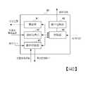
以下,針對本發明的實施形態,使用圖式來詳細地說明。 (第1實施形態) 圖1是顯示包含本揭示之第1實施形態的機器人控制裝置之機器人控制系統的一個構成例的方塊圖。Hereinafter, embodiments of the present invention will be described in detail using the drawings. (first embodiment) FIG. 1 is a block diagram showing a configuration example of a robot control system including a robot control device according to a first embodiment of the present disclosure.
如圖1所示,機器人控制系統10具備有PLC20、機器人教示操作盤30、機器人控制裝置40以及機器人50。 機器人控制裝置40已連接於PLC20、機器人教示操作盤30以及機器人50。機器人教示操作盤30亦可作為機器人控制裝置40的一部分來設置。 PLC20會規定機器人50所進行之組裝作業等的順序,並將動作指令輸出至機器人控制裝置40。機器人控制裝置40依據動作指令來控制機器人50。 機器人控制裝置40會將機器人50的現在位置轉發至PLC20。PLC20將該現在位置保存於PLC20內,並依據該現在位置且透過機器人控制裝置40來控制機器人50。As shown in FIG. 1 , the
在PLC20已準備有位置陣列(為預定之區域)來作為保存機器人50的現在位置之區域。例如,如圖1所示,在PLC20的位置陣列之POS[3]保存有:X=30、Y=20、Z=15、W=0、P=0、R=0,來作為機器人50的現在位置。PLC20在已被機器人控制裝置40輸入機器人50的現在位置的情況下,在被輸入之現在位置與保存於PLC20的位置陣列的POS[3]之位置不同的情況下,會將已保存於PLC20的位置陣列的POS[3]之位置覆寫為被輸入之現在位置。A position array (predetermined area) is prepared in the
機器人教示操作盤30是具備有顯示功能與資訊輸入功能之裝置,可為例如附觸控面板的液晶顯示裝置、液晶顯示裝置與鍵盤等。機器人教示操作盤30具備畫面31。在該畫面31中,作為設定項目而有位置索引號碼,並可藉由位置索引號碼來指定要保存於PLC20的哪個位置陣列要素。進而,在畫面31中,顯示有機器人50的現在位置、以及保存於PLC20的經指定的位置陣列要素之位置(PLC位置)等。The robot
例如,在圖1中,可在機器人教示操作盤30的畫面31顯示位置索引[3]來作為位置索引編號,並顯示:X=30、Y=20、Z=15、W=0、P=0、R=0,來作為機器人50的現在位置。又,可於機器人教示操作盤30的畫面顯示:X=30、Y=20、Z=15、W=0、P=0、R=0,來作為PLC位置。此PLC位置和保存於PLC20的位置陣列的POS[3]之位置為相同值。因此,使用者藉由觀看機器人教示操作盤30的畫面,可以確認機器人50的現在位置已正確地保存於PLC20的位置陣列之POS[3]。For example, in Fig. 1, the position index [3] can be displayed on the
使用者會使用機器人教示操作盤30來進行以下指示:將機器人50的現在位置轉發到PLC20之指示、及從PLC20取得保存於PLC20之位置或和位置有關連之關連資訊之指示。機器人教示操作盤30會將這些指示作為操作訊號並輸出至機器人控制裝置40。The user will use the robot
機器人50可為例如多關節機器人,並具備有機器人機構部51、以及安裝於機器人機構部51的前端的端接器(end effector)52。機器人50的現在位置是例如安裝於機器人50的機器人機構部51的前端之端接器52的位置。 機器人機構部51具有複數個關節軸,例如在圖1中為6個關節軸。在各個關節軸中分別設置有馬達。端接器52可為例如機械手、熔接炬(welding torch)、塗料噴霧器等。在各個馬達中設置有位置檢測部,例如編碼器。各個關節軸之位置檢測部的位置檢測訊號會被傳送至機器人控制裝置40。The
機器人控制裝置40會依據來自PLC20之動作指令,分別控制機器人機構部51的複數個關節軸的各個馬達。 又,機器人控制裝置40會從機器人50的機器人機構部51所輸出之位置檢測訊號,來求出機器人50的現在位置(X‚Y‚Z‚W‚P‚R)之值,並在機器人教示操作盤30的畫面31顯示位置(X‚Y‚Z‚W‚P‚R)之值來作為現在位置。The
圖2是顯示機器人控制裝置的構成的方塊圖。 如圖2所示,機器人控制裝置40具備轉發部41、資料取得部42、動作控制部43、控制部44以及顯示控制部45。Fig. 2 is a block diagram showing the configuration of the robot controller. As shown in FIG. 2 , the
轉發部41在有來自控制部44的轉發指示的情況下,會將機器人50的現在位置即X=30、Y=20、Z=15、W=0、P=0、R=0,轉發至PLC20。 資料取得部42在有來自控制部44的資料取得指示的情況下,會從PLC20取得保存於PLC20的位置陣列的POS[3]之X=30、Y=20、Z=15、W=0、P=0、R=0。When there is a forwarding instruction from the
動作控制部43會依據來自PLC20的動作指令,為了分別控制機器人50的機器人機構部51的複數個關節軸之各個馬達,而按各個馬達對機器人50輸出馬達控制指令。又,動作控制部43會將各個關節軸的位置檢測部之位置檢測訊號輸出至控制部44。The
控制部44會依據各個關節軸的位置檢測部的位置檢測訊號,來求出機器人50的現在位置(X‚Y‚Z‚W‚P‚R)之值,並記憶現在位置,並且輸出至顯示控制部45。 又,控制部44在從機器人教示操作盤30接收到的操作訊號為將機器人50的現在位置轉發到PLC20之操作訊號的情況下,會將已記憶之現在位置和轉發指示一起輸出至轉發部41。控制部44在從機器人教示操作盤30接收到的操作訊號為從PLC20取得保存於PLC20之位置或和位置有關連的資訊之操作訊號的情況下,會對資料取得部42輸出資料取得指示。 顯示控制部45會將位置(X‚Y‚Z‚W‚P‚R)之值顯示於機器人教示操作盤30的畫面31來作為現在位置。The
以上,已針對包含於機器人控制裝置40之功能方塊進行了說明。 為了實現這些功能方塊,機器人控制裝置40具備CPU(中央處理單元,Central Processing Unit)等之運算處理裝置。又,機器人控制裝置40也具備HDD(硬碟驅動器,Hard Disk Drive)之類的輔助記憶裝置、或RAM(隨機存取記憶體,Random Access Memory)之類的主記憶裝置,前述輔助記憶裝置保存有應用軟體以及OS(作業系統,Operating System)等之各種控制用程式,前述主記憶裝置用於保存運算處理裝置執行程式後暫時需要之資料。The functional blocks included in the
並且,在機器人控制裝置40中,運算處理裝置會從輔助記憶裝置讀入應用軟體或OS,並一邊使讀入之應用軟體或OS展開到主記憶裝置,一邊進行依據這些應用軟體或OS之運算處理。又,依據此運算結果來控制各個裝置所具備的各種硬體。藉此,可實現本實施形態之機器人控制裝置40的功能方塊。亦即,本實施形態可以藉由硬體與軟體協同合作來實現。In addition, in the
以下,針對機器人50的現在位置從X=30、Y=20、Z=15、W=30、P=20、R=15,改變成X=30、Y=20、Z=15、W=0、P=0、R=0的情況下之機器人控制裝置40的動作,使用圖3以及圖4來說明。圖3是顯示機器人控制裝置40的動作的流程圖。圖4是顯示機器人教示操作盤30的畫面的顯示資訊、與PLC20的位置陣列的保存資訊之變化的圖。Next, change the current position of the
如圖4所示,首先,在機器人教示操作盤30的畫面31中,作為機器人50的現在位置而顯示有X=30、Y=20、Z=15、W=30、P=20、R=15,作為PLC位置而顯示有X=30、Y=20、Z=15、W=30、P=20、R=15。將此時的畫面31的顯示資訊設為顯示資訊30A。於PLC20的位置陣列的POS[3]保存有X=30、Y=20、Z=15、W=30、P=20、R=15。將此時的保存資訊設為保存資訊20A。As shown in FIG. 4, first, on the
機器人控制裝置40使機器人50的機器人機構部51的前端之端接器52旋轉成:端接器52的位置成為X=30、Y=20、Z=15、W=0、P=0、R=0。The
在圖3之步驟S11中,機器人控制裝置40會依據來自機器人50的位置檢測訊號,如圖4所示地將機器人50的現行位置從X=30、Y=20、Z=15、W=30、P=20、R=15,變更成X=30、Y=20、Z=15、W=0、P=0、R=0,並顯示於機器人教示操作盤30的畫面31。如此一來,畫面31的顯示資訊會從顯示資訊30A改變成顯示資訊30B。 使用者觀看畫面31的顯示資訊30B的PLC位置,並辨識到在PLC20的位置陣列的POS[3]為仍舊保存有X=30、Y=20、Z=15、W=30、P=20、R=15之狀態。In step S11 of FIG. 3 , the
在步驟S12中,機器人控制裝置40會檢測是否已藉由使用者進行了機器人教示操作盤30的轉發操作。轉發操作是例如藉由使用者按壓機器人教示操作盤30的附觸控面板的液晶顯示裝置的未圖示的轉發鍵來進行。在已進行轉發操作的情況下會轉移至步驟S13,在未進行轉發操作的情況下會待機至進行轉發操作為止。In step S12 , the
在步驟S13中,機器人控制裝置40會將現在位置即X=30、Y=20、Z=15、W=0、P=0、R=0,轉發至PLC20。PLC20會將保存於位置陣列的POS[3]之X=30、Y=20、Z=15、W=30、P=20、R=15,覆寫為X=30、Y=20、Z=15、W=0、P=0、R=0。如此一來,保存資訊即從保存資訊20A變成保存資訊20B。In step S13 , the
在步驟S14中,機器人控制裝置40會檢測是否已藉由使用者進行了機器人教示操作盤30之PLC的位置資料取得操作。位置資料取得操作是以例如以下方式來進行:使用者選擇機器人教示操作盤30之附觸控面板的液晶顯示裝置的位置索引[3],並按壓未圖示的確認鍵。在已進行位置資料取得操作的情況下會轉移至步驟S15,在未進行位置資料取得操作的情況下會待機至進行位置資料取得操作為止。In step S14 , the
在步驟S15中,機器人控制裝置40會取得保存於PLC20的位置陣列的POS[3]之X=30、Y=20、Z=15、W=0、P=0、R=0。然後,機器人控制裝置40會將機器人教示操作盤30的畫面31的PLC位置變更為X=30、Y=20、Z=15、W=0、P=0、R=0。畫面31的顯示資訊會從顯示資訊30B改變成顯示資訊30C。In step S15 , the
使用者觀看機器人教示操作盤30的顯示資訊30C,並辨識出在PLC20的位置陣列的POS[3] 會被覆寫而保存有X=30、Y=20、Z=15、W=0、P=0、R=0。The user watches the
藉由以上的動作,使用者藉由觀看機器人教示操作盤30的畫面31,可以確認機器人的現在位置已正確地保存於PLC20的位置陣列。其結果,使用者變得毋須進行以下作業:在操作機器人教示操作盤30來將機器人的現在位置轉發到PLC20後,在PLC20的畫面上確認是否已保存該位置。Through the above operations, the user can confirm that the current position of the robot is correctly stored in the position array of the
(第2實施形態) 在第1實施形態中,是藉由使用者按壓機器人教示操作盤30之未圖示的確認鍵,來取得保存於PLC20的位置陣列的POS[3]之PLC位置,並於機器人教示操作盤30顯示PLC位置。 在本實施形態中,是藉由使用者按壓機器人教示操作盤30之未圖示的確認鍵,而從PLC20取得保存於PLC20之位置的關連資訊,並顯示於機器人教示操作盤30的畫面31。位置的關連資訊,可為例如參照保存於PLC之機器人的位置之PLC的功能方塊(FB)的名稱、教示有該FB之PLC程式的行號、以及FB的註解等。(Second Embodiment) In the first embodiment, the PLC position of POS [3] stored in the position array of the
圖5是顯示機器人教示操作盤30的畫面的顯示資訊、PLC20的保存資訊的圖。 例如,當使用者選擇位置索引[3],並按壓未圖示的確認鍵時,即可從PLC20取得PLC20內的位置陣列要素:參照POS[3]之PLC的功能方塊(FB)的名稱、教示該FB之PLC程式的行號、以及FB的註解;並顯示於機器人教示操作盤30的畫面31。藉此,可得知例如,此位置在名稱為「FB3」之FB中被參照、以及此「FB3」教示於PLC程式的第3行等。在FB附有註解等的情況下,其也會顯示於此畫面。在圖5中,作為註解而顯示意指機器人的拾取位置之“PICK_POS”。FIG. 5 is a diagram showing display information on the screen of the robot
(第3實施形態) 在第1實施形態中,當使用者按壓機器人教示操作盤30的未圖示的轉發鍵時,機器人控制裝置40會將機器人50的現在位置轉發至PLC20,PLC20會將保存於位置陣列的POS[3]之位置覆寫為從機器人控制裝置40轉發來之現在的位置。 在本實施形態中,是設為PLC20在將保存於位置陣列的POS[3]之位置覆寫為從機器人控制裝置40轉發來之現在的位置之前,會向使用者徵求覆寫的可否。(third embodiment) In the first embodiment, when the user presses an unillustrated transfer key on the robot
當由使用者在機器人教示操作盤30的畫面31上進行將機器人的現在位置轉發至PLC20之操作後,機器人控制裝置40之控制部44會接收操作訊號。控制部44在接收到操作訊號時,在所指定之位置陣列要素已經保存有位置的情況下,會在畫面31顯示「是否覆寫此位置?」這樣的訊息之確認用彈跳式視窗30D。圖6是顯示在畫面31所顯示之確認用彈跳式視窗的圖。在使用者選擇了「是」的情況下,可以將現在位置轉發至此位置陣列要素來覆寫。在使用者選擇了「否」的情況下,轉發會被中斷,且PLC20的位置陣列要素的位置不會被變更。After the user performs an operation of forwarding the current position of the robot to the
圖7是顯示第3實施形態的機器人控制裝置40的動作的流程圖。 圖7的流程圖是在圖3的流程圖的步驟S12與步驟S13之間設置有3個步驟S21、S22以及S23。 在步驟S12中,機器人控制裝置40會檢測是否已由使用者進行了機器人教示操作盤30之轉發操作,並在已進行轉發操作的情況下轉移至步驟S21。Fig. 7 is a flowchart showing the operation of the
在步驟S21中,機器人控制裝置40會取得保存於PLC的位置陣列要素之位置資料,並判斷該位置資料是否全部為“0”。機器人的位置資料除了X、Y、Z、W、P以及R之外也包含有擺姿,由於即使X、Y、Z、W、P以及R為“0”,仍然有擺姿之值,因此位置資料不會成為全部為“0”。 因為保存於PLC的位置陣列要素中的位置資料的初始值全部為“0”,所以在位置資料全部為“0”的情況下,可以判斷為尚未進行轉發處理。於是,機器人控制裝置40在位置資料全部為"0"的情況下,因為是首次的轉發,所以會在不將確認用彈跳式視窗30D顯示於畫面的情形下移轉至步驟S13,機器人控制裝置40會將現在位置即X=30、Y=20、Z=15、W=0、P=0、R=0轉發至PLC20。 另一方面,機器人控制裝置40在位置資料並非全部為"0"的情況下,會判斷為已經進行轉發處理,並轉移至步驟S22。In step S21 , the
在步驟S22中,機器人控制裝置40會在機器人教示操作盤30的畫面31顯示確認用彈跳式視窗30D,並轉移至步驟S23。 在步驟S23中,在使用者選擇了「是」的情況下,機器人控制裝置40會轉移至步驟S13。在使用者選擇了「否」的情況下,即不進行轉發,且PLC20的位置陣列要素的位置不會被變更。In step S22, the
以上已就本發明之各個實施形態進行了說明,包含於機器人控制裝置之各個構成部可以藉由硬體、軟體或其等之組合來實現。又,藉由包含於機器人控制裝置之各個構成部的每一個的協同合作而進行之機器人控制方法,也可以藉由硬體、軟體或其等的組合來實現。在此,所謂的藉由軟體來實現意指:藉由電腦讀入程式來執行而實現之作法。The various embodiments of the present invention have been described above, and the various components included in the robot control device can be realized by hardware, software, or a combination thereof. In addition, the robot control method performed by cooperation of each of the components included in the robot control device can also be realized by a combination of hardware, software, or the like. Here, the so-called realization by means of software means: the practice of realizing by reading in a program and executing it by a computer.
程式可以使用各種類型的非暫時的電腦可讀取的記錄媒體(non-transitory computer readable medium)來保存,並供給至電腦。非暫時的電腦可讀取的記錄媒體包含各種類型之有實體的記錄媒體(tangible storage medium)。非暫時的電腦可讀取的記錄媒體的例子包含:磁性記錄媒體(例如硬磁碟驅動機)、光磁記錄媒體(例如光碟)、CD-ROM(唯讀記憶體,Read Only Memory)、CD-R、CD-R/W、半導體記憶體(例如光罩式ROM、PROM(可程式唯讀記憶體,Programmable ROM)、EPROM(可抹除可程式唯讀記憶體,Erasable PROM)、 快閃ROM、RAM(隨機存取記憶體,random access memory))。The program can be stored using various types of non-transitory computer readable recording media (non-transitory computer readable medium), and can be supplied to the computer. The non-transitory computer-readable recording medium includes various types of tangible recording media (tangible storage medium). Examples of non-transitory computer-readable recording media include: magnetic recording media (such as hard disk drives), optical-magnetic recording media (such as optical discs), CD-ROM (Read Only Memory, Read Only Memory), CD -R, CD-R/W, semiconductor memory (such as mask ROM, PROM (programmable read-only memory, Programmable ROM), EPROM (erasable programmable read-only memory, Erasable PROM), flash ROM, RAM (random access memory, random access memory)).
上述之實施形態雖然是本發明之較佳的實施形態,但並非要將本發明的範圍僅限定於上述實施形態,且在不脫離本發明之要旨的範圍內可進行施加了各種變更之形態下的實施。The above-mentioned embodiments are preferred embodiments of the present invention, but the scope of the present invention is not limited to the above-mentioned embodiments, and various changes can be made without departing from the gist of the present invention. implementation.
本揭示之機器人控制裝置、機器人控制系統及機器人控制方法包含上述之實施形態,且可以採取具有如下之構成的各式各樣的的實施形態。The robot control device, robot control system, and robot control method of the present disclosure include the above-mentioned embodiments, and various embodiments having the following configurations can be adopted.
(1)一種機器人控制裝置(例如機器人控制裝置40),其和可程式邏輯控制器(例如PLC20)連接並控制機器人(例如機器人50),前述機器人控制裝置具備有: 轉發部(例如轉發部41),為了將前述機器人的現在位置保存至前述可程式邏輯控制器內的預定的區域,而將該現在位置轉發至前述可程式邏輯控制器; 取得部(例如資料取得部42),從前述可程式邏輯控制器取得已保存於前述可程式邏輯控制器之前述現在位置或前述現在位置的關連資訊;及 顯示控制部(例如顯示控制部45),將所取得的前述現在位置或前述關連資訊顯示於機器人教示操作盤(例如機器人教示操作盤30)的畫面。 根據此機器人控制裝置,在將機器人的現在位置轉發至PLC來保存時,變得毋須交替地進行機器人教示操作盤上的轉發操作與PLC的畫面上的確認操作,而可以只以機器人教示操作盤來完成一連串的操作。(1) A robot control device (such as a robot control device 40), which is connected with a programmable logic controller (such as PLC20) and controls a robot (such as a robot 50). The aforementioned robot control device has: The forwarding unit (such as the forwarding unit 41), in order to save the current position of the robot to a predetermined area in the aforementioned programmable logic controller, and forward the current position to the aforementioned programmable logic controller; The acquisition unit (such as the data acquisition unit 42) acquires the aforementioned current position or the related information of the aforementioned current position saved in the aforementioned programmable logic controller from the aforementioned programmable logic controller; and The display control unit (for example, the display control unit 45 ) displays the acquired current position or the related information on the screen of the robot teaching operation panel (for example, the robot teaching operation panel 30 ). According to this robot control device, when transferring the current position of the robot to the PLC for storage, it becomes unnecessary to alternately perform the forwarding operation on the robot teaching operation panel and the confirmation operation on the PLC screen, and it is possible to use only the robot teaching operation panel. to complete a series of operations.
(2)如上述(1)記載之機器人控制裝置,其中在已保存於前述可程式邏輯控制器之前述現在位置被可程式邏輯控制器程式內的功能方塊所參照的情況下,前述取得部會取得該功能方塊的資訊,且前述顯示控制部會在前述機器人教示操作盤的畫面進行顯示。(2) The robot control device described in (1) above, wherein when the current position stored in the programmable logic controller is referred to by a function block in the program of the programmable logic controller, the acquisition unit will The information of the function block is acquired, and the display control unit displays it on the screen of the teaching operation panel of the robot.
(3)如上述(1)或(2)記載之機器人控制裝置,其在將前述現在位置轉發至前述可程式邏輯控制器的情況下,在前述預定的區域已經保存有前述現在位置的情況下,會在前述機器人教示操作盤的畫面顯示用來確認是否將其覆寫之彈跳式視窗。(3) The robot control device described in (1) or (2) above, when transferring the current position to the programmable logic controller, if the current position is already stored in the predetermined area , a pop-up window for confirming whether to overwrite will be displayed on the screen of the aforementioned robot teaching operation panel.
(4)如上述(1)至(3)中任一項記載之機器人控制裝置,其包含前述機器人教示操作盤。(4) The robot control device according to any one of (1) to (3) above, which includes the robot teaching operation panel.
(5)一種機器人控制系統,具備有上述(1)至(4)中任一項記載之機器人控制裝置(例如機器人控制裝置40)、及和該機器人控制裝置連接之可程式邏輯控制器。 根據此機器人控制系統,在將機器人的現在位置轉發至PLC來保存時,變得毋須交替地進行機器人教示操作盤上的轉發操作與PLC的畫面上的確認操作,而可以只以機器人教示操作盤來完成一連串的操作。(5) A robot control system comprising the robot control device described in any one of (1) to (4) above (for example, the robot control device 40 ), and a programmable logic controller connected to the robot control device. According to this robot control system, when transferring the current position of the robot to the PLC for storage, it becomes unnecessary to alternately perform the forwarding operation on the robot teaching operation panel and the confirmation operation on the PLC screen, and it is possible to use only the robot teaching operation panel to complete a series of operations.
(6)一種機器人控制方法,利用可程式邏輯控制器(例如PLC20)、及和該可程式邏輯控制器連接之機器人控制裝置(例如機器人控制裝置40)來控制機器人,前述機器人控制方法會進行以下步驟: 為了將前述機器人的現在位置保存至前述可程式邏輯控制器內的預定的區域,前述機器人控制裝置將該現在位置轉發到前述可程式邏輯控制器; 前述機器人控制裝置從前述可程式邏輯控制器取得已保存於前述可程式邏輯控制器之前述現在位置或前述現在位置的關連資訊; 前述機器人控制裝置將所取得的前述現在位置或前述關連資訊顯示於機器人教示操作盤的畫面。 根據此機器人控制方法,在將機器人的現在位置轉發至PLC來保存時,變得毋須交替地進行機器人教示操作盤上的轉發操作與PLC的畫面上的確認操作,而可以只以機器人教示操作盤來完成一連串的操作。(6) A robot control method, utilizing a programmable logic controller (such as PLC20) and a robot control device (such as a robot control device 40) connected to the programmable logic controller to control the robot, the aforementioned robot control method will perform the following step: In order to save the current position of the robot to a predetermined area in the programmable logic controller, the robot control device forwards the current position to the programmable logic controller; The aforementioned robot control device obtains the aforementioned current position or the related information of the aforementioned current position saved in the aforementioned programmable logic controller from the aforementioned programmable logic controller; The aforementioned robot control device displays the acquired aforementioned current position or aforementioned related information on the screen of the robot teaching operation panel. According to this robot control method, when transferring the current position of the robot to the PLC for storage, it becomes unnecessary to alternately perform the forwarding operation on the robot teaching operation panel and the confirmation operation on the PLC screen, and it is possible to use only the robot teaching operation panel to complete a series of operations.
10:機器人控制系統 20:PLC 20A,20B:保存資訊 30:機器人教示操作盤 30A,30B,30C:顯示資訊 30D:確認用彈跳式視窗 31:畫面 40:機器人控制裝置 41:轉發部 42:資料取得部 43:動作控制部 44:控制部 45:顯示控制部 50:機器人 51:機器人機構部 52:端接器 S11~S15,S21~S23:步驟10: Robot control system 20:
圖1是顯示包含本揭示之第1實施形態的機器人控制裝置之機器人控制系統的一個構成例的方塊圖。 圖2是顯示第1實施形態的機器人控制裝置之構成的方塊圖。 圖3是顯示第1實施形態的機器人控制裝置的動作的流程圖。 圖4是顯示第1實施形態中的機器人教示操作盤的畫面的顯示資訊、與PLC的位置陣列的保存資訊之變化的圖。 圖5是顯示本揭示之第2實施形態中的機器人教示操作盤的畫面的顯示資訊、與PLC的保存資訊的圖。 圖6是顯示藉由本揭示之第3實施形態的機器人控制裝置而在機器人教示操作盤的畫面所顯示之確認用彈跳式視窗的圖。 圖7是顯示第3實施形態的機器人控制裝置的動作的流程圖。FIG. 1 is a block diagram showing a configuration example of a robot control system including a robot control device according to a first embodiment of the present disclosure. Fig. 2 is a block diagram showing the configuration of the robot controller according to the first embodiment. Fig. 3 is a flowchart showing the operation of the robot controller according to the first embodiment. Fig. 4 is a diagram showing changes in information displayed on the screen of the robot teaching operation panel and stored information in the position array of the PLC in the first embodiment. Fig. 5 is a diagram showing information displayed on the screen of the robot teaching operation panel and information stored in the PLC according to the second embodiment of the present disclosure. Fig. 6 is a diagram showing pop-up windows for confirmation displayed on the screen of the robot teaching operation panel by the robot control device according to the third embodiment of the present disclosure. Fig. 7 is a flowchart showing the operation of the robot controller according to the third embodiment.
10:機器人控制系統10: Robot control system
20:PLC20:PLC
30:機器人教示操作盤30: Robot teaching operation panel
31:畫面31: Screen
40:機器人控制裝置40:Robot control device
50:機器人50: Robot
51:機器人機構部51:Robot Mechanism Department
52:端接器52: terminator
Claims (6)
Translated fromChineseApplications Claiming Priority (2)
| Application Number | Priority Date | Filing Date | Title |
|---|---|---|---|
| WOPCT/JP2021/014184 | 2021-04-01 | ||
| PCT/JP2021/014184WO2022208849A1 (en) | 2021-04-01 | 2021-04-01 | Robot control device, robot control system, and robot control method |
Publications (1)
| Publication Number | Publication Date |
|---|---|
| TW202239547Atrue TW202239547A (en) | 2022-10-16 |
Family
ID=83457257
Family Applications (1)
| Application Number | Title | Priority Date | Filing Date |
|---|---|---|---|
| TW111108411ATW202239547A (en) | 2021-04-01 | 2022-03-08 | Robot control device, robot control system, and robot control method |
Country Status (6)
| Country | Link |
|---|---|
| US (1) | US20240116191A1 (en) |
| JP (1) | JP7572542B2 (en) |
| CN (1) | CN117043692A (en) |
| DE (1) | DE112021006836T5 (en) |
| TW (1) | TW202239547A (en) |
| WO (1) | WO2022208849A1 (en) |
Families Citing this family (1)
| Publication number | Priority date | Publication date | Assignee | Title |
|---|---|---|---|---|
| WO2021235324A1 (en)* | 2020-05-18 | 2021-11-25 | ファナック株式会社 | Robot control device and robot system |
Family Cites Families (8)
| Publication number | Priority date | Publication date | Assignee | Title |
|---|---|---|---|---|
| JPH11296217A (en)* | 1998-04-03 | 1999-10-29 | Hitachi Seiki Co Ltd | Method and apparatus for transferring program file in NC device |
| JP2003117863A (en)* | 2001-10-16 | 2003-04-23 | Fanuc Ltd | Robot simulation device |
| JP4424133B2 (en)* | 2004-09-24 | 2010-03-03 | 株式会社ジェイテクト | Input/Output Data Management Device |
| JP4676544B2 (en)* | 2009-05-29 | 2011-04-27 | ファナック株式会社 | Robot control device for controlling a robot for supplying and taking out workpieces from a machine tool |
| JP2019025562A (en)* | 2017-07-27 | 2019-02-21 | ファナック株式会社 | Robot control device and production system |
| JP6969283B2 (en)* | 2017-10-25 | 2021-11-24 | オムロン株式会社 | Control system |
| JP7095417B2 (en)* | 2018-06-06 | 2022-07-05 | オムロン株式会社 | Control system, control system control method, and control system program |
| JP6829223B2 (en)* | 2018-06-08 | 2021-02-10 | ファナック株式会社 | Remote management device and remote management method |
- 2021
- 2021-04-01USUS18/276,996patent/US20240116191A1/enactivePending
- 2021-04-01WOPCT/JP2021/014184patent/WO2022208849A1/ennot_activeCeased
- 2021-04-01CNCN202180096197.1Apatent/CN117043692A/enactivePending
- 2021-04-01JPJP2023510118Apatent/JP7572542B2/enactiveActive
- 2021-04-01DEDE112021006836.9Tpatent/DE112021006836T5/enactivePending
- 2022
- 2022-03-08TWTW111108411Apatent/TW202239547A/enunknown
Also Published As
| Publication number | Publication date |
|---|---|
| WO2022208849A1 (en) | 2022-10-06 |
| US20240116191A1 (en) | 2024-04-11 |
| JP7572542B2 (en) | 2024-10-23 |
| JPWO2022208849A1 (en) | 2022-10-06 |
| CN117043692A (en) | 2023-11-10 |
| DE112021006836T5 (en) | 2023-11-16 |
Similar Documents
| Publication | Publication Date | Title |
|---|---|---|
| US11813750B2 (en) | Programming support apparatus, robot system, and programming support method | |
| US7194396B2 (en) | Simulation device | |
| US6853881B2 (en) | Robot information processing system | |
| US10534876B2 (en) | Simulation device and simulation method that carry out simulation of operation of robot system, and recording medium that records computer program | |
| JP6434434B2 (en) | A processing robot system that connects a processing device to a robot for processing | |
| JP2020049569A (en) | Support device for creating program of robot | |
| US20220281103A1 (en) | Information processing apparatus, robot system, method of manufacturing products, information processing method, and recording medium | |
| JP2019025620A (en) | Robot system and operation method thereof | |
| KR102198204B1 (en) | Simulation device | |
| TW202239547A (en) | Robot control device, robot control system, and robot control method | |
| JP2013226602A (en) | Industrial machine system | |
| CN116197894A (en) | Program creating device and program | |
| CN120379798A (en) | Apparatus, method and computer program for adjusting gesture of robot | |
| JP4566904B2 (en) | System, control program and recording medium recording the program, and image data creation program and recording medium recording the program | |
| WO2023276149A1 (en) | Optimization assistance device | |
| CN117222500A (en) | Programming device and program | |
| WO2020067256A1 (en) | Control device | |
| US20230173670A1 (en) | Information processing apparatus, system, information processing method, method of manufacturing products, and recording medium | |
| EP4610003A1 (en) | Robot controller and method for comparing control software before and after update | |
| JP2001042907A (en) | Sequence controller | |
| WO2023148821A1 (en) | Programming device | |
| WO2023171722A1 (en) | Program generation device and program generation method | |
| JP2025099234A (en) | Robot Control Device | |
| CN120152828A (en) | Speed reducer selection auxiliary device | |
| JPH08286734A (en) | Programmable display device |