Movatterモバイル変換


[0]ホーム

URL:


TW202239085A - Connector assembly that comprises a hood, a receptacle connector, an insertion and removal module, a heat dissipater, and a heat dissipater lifting structure - Google Patents

Connector assembly that comprises a hood, a receptacle connector, an insertion and removal module, a heat dissipater, and a heat dissipater lifting structure
Download PDF

Info

Publication number
TW202239085A
TW202239085ATW110109993ATW110109993ATW202239085ATW 202239085 ATW202239085 ATW 202239085ATW 110109993 ATW110109993 ATW 110109993ATW 110109993 ATW110109993 ATW 110109993ATW 202239085 ATW202239085 ATW 202239085A
Authority
TW
Taiwan
Prior art keywords
lifting
radiator
moving part
pluggable module
moving
Prior art date
Application number
TW110109993A
Other languages
Chinese (zh)
Other versions
TWI763384B (en
Inventor
陳建智
Original Assignee
台灣莫仕股份有限公司
美商莫仕有限公司
Priority date (The priority date is an assumption and is not a legal conclusion. Google has not performed a legal analysis and makes no representation as to the accuracy of the date listed.)
Filing date
Publication date
Application filed by 台灣莫仕股份有限公司, 美商莫仕有限公司filedCritical台灣莫仕股份有限公司
Priority to TW110109993ApriorityCriticalpatent/TWI763384B/en
Application grantedgrantedCritical
Publication of TWI763384BpublicationCriticalpatent/TWI763384B/en
Publication of TW202239085ApublicationCriticalpatent/TW202239085A/en

Links

Images

Landscapes

Abstract

A connector assembly comprises a hood, a receptacle connector, an insertion and removal module, a heat dissipater, and a heat dissipater lifting structure. The hood has an insertion space in an interior thereof. The receptacle connector is arranged in the insertion space of the hood. The insertion and removal module is for inserting into the insertion space of the hood to connect with the receptacle connector. The heat dissipater comprises a thermocouple structure protruded downward. The thermocouple structure comprises a thermal interfacing material arranged on a bottom surface. The heat dissipater lifting structure comprises a lifting section that pushes and ejects a rear section of the heat dissipater. When the insertion and removal module is not inserted into the hood, the lifting section of the heat dissipater lifting structure is at an operation position for lifting upward the rear section of the heat dissipater; when the insertion and removal module is inserted into the insertion space of the hood, the lifting section of the heat dissipater lifting structure is moved to a non-operation position to lower down the rear section of the heat dissipater.

Description

Translated fromChinese
連接器組件connector assembly

本發明是有關於一種連接器組件,特別是指一種具有散熱器的連接器組件。The invention relates to a connector assembly, in particular to a connector assembly with a radiator.

中國發明專利公告號CN109283635B(對應美國發明專利公告號US10,295,767 B2)公開了一種用於光學收發器的散熱器組件。其公開了散熱器組件的散熱器的底部包括引導散熱器相對於凸輪結構運動的前端狹槽和後端傾斜的狹槽。當收發器部分地插入頂部支架時,散熱器的熱界面材料與收發器之間存在小的間隙。此時,凸輪結構與狹槽接觸,因此散熱器相對於收發器位於較高的位置。當收發器移動至頂部支架的行程末端之後,後端連接器介面接合連接器電子元件。此時,凸輪結構相對於狹槽移動,因此散熱器相對於收發器下降。在下降後的位置,熱界面材料將接觸收發器的接觸表面。夾具連結散熱器並提供散熱器向下的壓力以將散熱器向下推並使其接觸收發器。當收發器將自頂部支架退出時,彈簧朝前推動凸輪結構的力大於夾具向下的壓力,因此,散熱器被抬升以遠離收發器,這降低了在收發器插入或移除的接觸行程中因剪力損壞熱界面材料的可能性。Chinese invention patent announcement number CN109283635B (corresponding to US invention patent announcement number US10,295,767 B2) discloses a radiator assembly for an optical transceiver. It discloses that the bottom of the radiator of the radiator assembly includes front slots and rear inclined slots that guide the movement of the radiator relative to the cam structure. When the transceiver is partially inserted into the top bracket, there is a small gap between the thermal interface material of the heat sink and the transceiver. At this point, the cam structure is in contact with the slot, so the heat sink is positioned higher relative to the transceiver. After the transceiver has moved to the end of travel of the top bracket, the rear connector interface engages the connector electronics. At this point, the cam structure moves relative to the slot, so the heat sink is lowered relative to the transceiver. In the lowered position, the thermal interface material will contact the contact surface of the transceiver. The clamp is attached to the heat sink and provides downward pressure on the heat sink to push the heat sink down and into contact with the transceiver. When the transceiver will be withdrawn from the top bracket, the force of the spring pushing the cam structure forward is greater than the downward pressure of the clamp, so the heat sink is lifted away from the transceiver, which reduces the contact stroke during the insertion or removal of the transceiver Potential for shear damage to thermal interface material.

上述先前技術是通過凸輪結構來撐高散熱器,以在散熱器與收發器之間形成間隙,使收發器在部分插入時不會接觸到熱界面材料。但是凸輪結構如何將散熱器平行地提升高度缺乏具體可以實施的構造,而且平行地抬高整個散熱器需要兩個凸輪結構(前方的凸輪結構與後方的凸輪結構)才能達成,另一方面來說,在收發器移動至頂部支架的行程末端之後,也需要兩個凸輪結構同時作用才能進一步向下推動散熱器並使得收發器接觸散熱器的熱界面材料。The above-mentioned prior art uses a cam structure to elevate the heat sink to form a gap between the heat sink and the transceiver, so that the transceiver will not contact the thermal interface material when it is partially inserted. However, how the cam structure raises the height of the radiator in parallel lacks a specific structure that can be implemented, and raising the entire radiator in parallel requires two cam structures (the front cam structure and the rear cam structure) to achieve. On the other hand, , after the transceiver moves to the end of travel of the top bracket, it also requires two cam structures acting simultaneously to push the heat sink further down and make the transceiver contact the thermal interface material of the heat sink.

因此,本發明之一目的,即在提供一種能改善先前技術中至少一缺點的連接器組件。Therefore, it is an object of the present invention to provide a connector assembly that can improve at least one of the disadvantages of the prior art.

於是,本發明連接器組件在一些實施態樣中,是包含罩體、插座連接器、可插拔模組、散熱器、施壓構件,以及散熱器抬升構造。所述罩體具有位於內部的插接空間,以及構成所述插接空間的頂壁,所述頂壁具有窗口。所述插座連接器設於所述罩體的插接空間內。所述可插拔模組用以插入所述罩體的插接空間以與所述插座連接器對接。所述散熱器具有向下凸伸的熱耦合結構,所述熱耦合結構具有位於前方的保護坡部、位於所述保護坡部後方的熱耦合部,以及設於所述熱耦合部的底面的熱界面材料。所述施壓構件組裝所述散熱器至所述罩體的頂壁,並對所述散熱器施加朝下的作用力。所述散熱器抬升構造具有位於所述施壓構件的後方且用以推頂所述散熱器的後段處的抬升部。當所述可插拔模組未插入所述罩體的插接空間,所述散熱器抬升構造的抬升部位於將所述散熱器的後段抬升的作用位置,此時所述熱界面材料朝後且朝上傾斜地延伸;當所述可插拔模組插入所述罩體的插接空間並與所述插座連接器對接,所述可插拔模組作用於所述散熱器抬升構造,以使所述散熱器抬升構造的抬升部移動至使所述散熱器的後段下降的非作用位置, 此時所述施壓構件對所述散熱器施加的作用力,使所述熱界面材料自傾斜地抬高的狀態移動至相對地水平且通過所述窗口接觸所述可插拔模組的狀態。Therefore, in some embodiments, the connector assembly of the present invention includes a cover body, a socket connector, a pluggable module, a heat sink, a pressing member, and a heat sink lifting structure. The cover body has a plugging space located inside, and a top wall constituting the plugging space, and the top wall has a window. The socket connector is arranged in the insertion space of the cover body. The pluggable module is used for inserting into the plugging space of the housing to be connected with the socket connector. The heat sink has a downwardly protruding thermal coupling structure, the thermal coupling structure has a protective slope at the front, a thermal coupling at the rear of the protective slope, and a bottom surface of the thermal coupling. thermal interface material. The pressing member assembles the radiator to the top wall of the housing, and exerts a downward force on the radiator. The radiator lifting structure has a lifting portion at the rear of the pressing member for pushing up the rear section of the radiator. When the pluggable module is not inserted into the insertion space of the cover body, the lifting part of the radiator lifting structure is located at the active position of lifting the rear section of the radiator, and at this time, the thermal interface material faces backward And extend upwards obliquely; when the pluggable module is inserted into the insertion space of the cover and docked with the socket connector, the pluggable module acts on the lifting structure of the radiator, so that The lifting part of the radiator lifting structure moves to the inactive position where the rear section of the radiator is lowered. At this time, the force exerted by the pressing member on the radiator makes the thermal interface material self-obliquely lift. The high state moves to a state that is relatively horizontal and contacts the pluggable module through the window.

在一些實施態樣中,當所述散熱器抬升構造的抬升部位於所述作用位置且所述散熱器的後段被抬升時,所述保護坡部的底部低於所述熱界面材料的底部。In some implementation aspects, when the lifting portion of the radiator lifting structure is at the active position and the rear section of the radiator is lifted, the bottom of the protection slope is lower than the bottom of the thermal interface material.

在一些實施態樣中,所述熱耦合結構於所述保護坡部與所述熱耦合部之間形成有一凹溝,所述熱界面材料的前端延伸至所述凹溝內。In some implementation aspects, the thermal coupling structure forms a groove between the protection slope portion and the thermal coupling portion, and the front end of the thermal interface material extends into the groove.

在一些實施態樣中,所述散熱器抬升構造設置在所述罩體內且位於所述頂壁下方,所述散熱器抬升構造包括固定件、移動件及支撐彈簧。所述固定件組裝於所述罩體,所述固定件具有朝後延伸的彈片,以及設置於所述彈片末端的所述抬升部。所述移動件可相對所述固定件前後移動地設置於所述固定件,所述移動件具有對應於所述抬升部的避讓部。所述支撐彈簧設置於所述移動件並提供給所述移動件彈性復位力。當所述可插拔模組未插入所述罩體的插接空間,所述固定件的抬升部受到所述移動件的支撐而位於所述作用位置;當所述可插拔模組插入所述罩體的插接空間並與所述插座連接器對接,所述可插拔模組推動所述移動件,使所述移動件的避讓部朝後移動並避讓所述抬升部,以使所述固定件的抬升部移動至使所述非作用位置;當所述可插拔模組自所述罩體的插接空間退出,所述支撐彈簧提供彈性復位力以朝前地推回所述移動件,以使所述固定件的抬升部受到所述移動件的支撐而回復至所述作用位置。In some implementation aspects, the radiator elevating structure is disposed in the housing and located below the top wall, and the radiator elevating structure includes a fixing part, a moving part and a supporting spring. The fixing part is assembled on the cover body, the fixing part has an elastic piece extending backward, and the lifting part is arranged at the end of the elastic piece. The moving part is arranged on the fixing part so as to be movable back and forth relative to the fixing part, and the moving part has an escape part corresponding to the lifting part. The supporting spring is arranged on the moving part and provides an elastic restoring force to the moving part. When the pluggable module is not inserted into the insertion space of the cover, the lifting part of the fixing part is supported by the moving part and is located at the active position; when the pluggable module is inserted into the The insertion space of the cover body and docking with the socket connector, the pluggable module pushes the moving part, so that the avoiding part of the moving part moves backward and avoids the lifting part, so that the The lifting part of the fixing part moves to the inactive position; when the pluggable module withdraws from the insertion space of the cover, the supporting spring provides elastic restoring force to push back the the moving part, so that the lifting part of the fixing part is supported by the moving part to return to the active position.

在一些實施態樣中,所述抬升部是一體構造形成於所述彈片末端且朝上翻折的捲曲片體,所述避讓部為形成於所述移動件且用以容納所述抬升部的容納孔,所述移動件還具有位於所述避讓部的後端的推高部,所述推高部具有朝向上方的頂高面,以及自所述頂高面的前緣朝前並朝下傾斜地延伸的推高斜面,所述頂高面用以在所述可插拔模組未插入所述罩體的插接空間時支撐所述固定件的抬升部至所述作用位置,所述推高斜面用以在所述可插拔模組自所述罩體的插接空間退出時將所述固定件的抬升部逐漸朝上推頂。In some implementation aspects, the lifting portion is an integrally formed curled sheet formed at the end of the elastic piece and turned upwards, and the avoiding portion is formed on the moving part and is used to accommodate the lifting portion The accommodating hole, the moving part also has a push-up portion located at the rear end of the avoidance portion, the push-up portion has a top surface facing upwards, and a front edge of the top surface slopes forward and downward an extended push-up slope, the top surface is used to support the lifting part of the fixing part to the active position when the pluggable module is not inserted into the insertion space of the cover body, the push-up The slope is used for gradually pushing the lifting part of the fixing part upward when the pluggable module withdraws from the insertion space of the cover.

在一些實施態樣中,所述支撐彈簧是設置在所述移動件與所述固定件之間的圈狀彈簧。In some implementation aspects, the supporting spring is a coil spring arranged between the moving part and the fixing part.

在一些實施態樣中,所述散熱器抬升構造設置在所述罩體內且位於所述頂壁下方,所述散熱器抬升構造包括固定件、移動件及支撐彈簧。所述固定件組裝於所述罩體。所述移動件可相對所述固定件前後移動地設置於所述固定件,所述移動件具有所述抬升部,所述散熱器具有對應於所述抬升部的避讓部。所述支撐彈簧設置於所述移動件並提供給所述移動件彈性復位力。當所述可插拔模組未插入所述罩體的插接空間,所述移動件的抬升部位於所述作用位置;當所述可插拔模組插入所述罩體的插接空間並與所述插座連接器對接,所述可插拔模組推動所述移動件,使所述移動件的抬升部朝後移動至被所述散熱器的避讓部避讓的所述非作用位置;當所述可插拔模組自所述罩體的插接空間退出,所述支撐彈簧提供彈性復位力以朝前地推回所述移動件,以使所述移動件的抬升部朝前移動以回復至所述作用位置。In some implementation aspects, the radiator elevating structure is disposed in the housing and located below the top wall, and the radiator elevating structure includes a fixing part, a moving part and a supporting spring. The fixing part is assembled on the cover body. The moving part is arranged on the fixing part so as to be movable back and forth relative to the fixing part, the moving part has the lifting part, and the radiator has an escape part corresponding to the lifting part. The supporting spring is arranged on the moving part and provides an elastic restoring force to the moving part. When the pluggable module is not inserted into the insertion space of the cover, the lifting part of the moving part is at the active position; when the pluggable module is inserted into the insertion space of the cover and Docking with the socket connector, the pluggable module pushes the moving part, so that the lifting part of the moving part moves backward to the inactive position avoided by the avoiding part of the radiator; when The pluggable module withdraws from the insertion space of the cover, and the support spring provides an elastic restoring force to push back the moving part forward, so that the lifting part of the moving part moves forward to return to the position of action.

在一些實施態樣中,所述抬升部呈一體構造形成於所述移動件的凸塊,所述避讓部為形成於所述散熱器且用以容納所述抬升部的凹槽。In some implementation aspects, the lifting portion is integrally formed on a protrusion of the moving member, and the avoiding portion is a groove formed on the heat sink for accommodating the lifting portion.

在一些實施態樣中,所述支撐彈簧是一體構造地形成在所述移動件的彈片結構。In some implementation aspects, the support spring is integrally formed on the elastic structure of the moving member.

在一些實施態樣中,所述散熱器抬升構造包括移動件及支撐彈簧,所述移動件設置於所述散熱器的後段且位於所述罩體外,所述移動件可相對所述散熱器前後移動地通過所述支撐彈簧連接於所述散熱器,所述移動件具有所述抬升部,所述散熱器具有對應於所述抬升部的避讓部。所述支撐彈簧提供給所述移動件彈性復位力。當所述可插拔模組未插入所述罩體的插接空間,所述移動件的抬升部位於所述作用位置;當所述可插拔模組插入所述罩體的插接空間並與所述插座連接器對接,所述可插拔模組推動所述移動件,使所述移動件的抬升部朝後移動至被所述散熱器的避讓部避讓的所述非作用位置;當所述可插拔模組自所述罩體的插接空間退出,所述支撐彈簧提供彈性復位力以朝前地推回所述移動件,以使所述移動件的抬升部朝前移動以回復至所述作用位置。In some implementation aspects, the radiator lifting structure includes a moving part and a supporting spring, the moving part is arranged at the rear section of the radiator and is located outside the cover, and the moving part can move forward and backward relative to the radiator The moving part is connected to the radiator through the supporting spring, the moving part has the lifting part, and the radiator has a evacuation part corresponding to the lifting part. The support spring provides an elastic reset force for the moving part. When the pluggable module is not inserted into the insertion space of the cover, the lifting part of the moving part is at the active position; when the pluggable module is inserted into the insertion space of the cover and Docking with the socket connector, the pluggable module pushes the moving part, so that the lifting part of the moving part moves backward to the inactive position avoided by the avoiding part of the radiator; when The pluggable module withdraws from the insertion space of the cover, and the support spring provides an elastic restoring force to push back the moving part forward, so that the lifting part of the moving part moves forward to return to the position of action.

在一些實施態樣中,所述抬升部呈一體構造形成於所述移動件的凸塊,所述避讓部為形成於所述散熱器且用以容納所述抬升部的凹槽。In some implementation aspects, the lifting portion is integrally formed on a protrusion of the moving member, and the avoiding portion is a groove formed on the heat sink for accommodating the lifting portion.

在一些實施態樣中,所述支撐彈簧是設置在所述移動件與所述散熱器之間的圈狀彈簧。In some implementation aspects, the supporting spring is a coil spring arranged between the moving member and the heat sink.

本發明連接器組件通過所述抬升部抬高所述散熱器的後段,使所述散熱器及所述散熱器的熱界面材料朝後且朝上傾斜地延伸,另外,再加上所述散熱器的位於前方的所述保護坡部之配合,能使所述可插拔模組部分地插入所述罩體時不會直接接觸到所述熱界面材料,並且,使所述可插拔模組能先接觸到所述保護坡部,以避免所述熱界面材料在所述可插拔模組的插入過程中被所述可插拔模組刮破或磨損。The connector assembly of the present invention raises the rear section of the heat sink through the lifting portion, so that the heat sink and the thermal interface material of the heat sink extend backward and upward obliquely, and in addition, the heat sink The cooperation of the protective slope at the front can prevent the pluggable module from directly contacting the thermal interface material when it is partially inserted into the cover, and makes the pluggable module The protection slope can be contacted first, so as to prevent the thermal interface material from being scratched or worn by the pluggable module during insertion of the pluggable module.

在本發明被詳細描述之前,應當注意在以下的說明內容中,類似的元件是以相同的編號來表示。Before the present invention is described in detail, it should be noted that in the following description, similar elements are denoted by the same numerals.

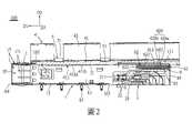
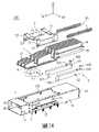
參閱圖1至圖4,本發明連接器組件100之一第一實施例,包含一罩體1、一插座連接器2、一可插拔模組3、一散熱器4、一施壓構件5,以及一散熱器抬升構造6。需要說明的是,所述罩體1、所述插座連接器2、所述散熱器4、所述施壓構件5與所述散熱器抬升構造6的數量皆可以各自依照需求做調整且可為堆疊或組合的構造,不以本第一實施例中的數量為限制。1 to 4, a first embodiment of theconnector assembly 100 of the present invention includes acover body 1, asocket connector 2, apluggable module 3, aheat sink 4, and apressure member 5 , and aradiator lifting structure 6. It should be noted that the number of thecover body 1, thesocket connector 2, theradiator 4, thepressing member 5 and theradiator elevating structure 6 can be adjusted according to requirements and can be The stacked or combined structure is not limited to the quantity in the first embodiment.

該罩體1舉例來說是以金屬薄板經由模具沖壓加工、彎折所構造而成,並用以導引該可插拔模組3及產生屏蔽電磁干擾之作用。該罩體1用以設置於一電路板(圖未示)且沿一前後方向D1(箭頭方向為前,反向為後)延伸。該罩體1具有一頂壁11、與該頂壁11沿一上下方向D2 (箭頭方向為上,反向為下)相間隔的一底壁12、沿一左右方向D3 (箭頭方向為右,反向為左)相間隔且連接於該頂壁11與該底壁12之間的兩個側壁13、連接於該頂壁11與該兩側壁13的後緣的一後壁14,以及自該兩側壁13朝下延伸並適用於固定在所述電路板上及/或連接到接地軌跡(圖未示)的多個插腳15。另外,該罩體1還具有由該頂壁11、該底壁12、該兩側壁13與該後壁14共同構成界定且位於內部的一插接空間16、位於前端且連通於該插接空間16並供該可插拔模組3插入的一前端插口161、形成於該頂壁11且自該頂壁11的前段處朝後延伸並連通於該插接空間16的一窗口162,以及位於該底壁12後方且連通該插接空間16的一底部開口163。Thecover body 1 is, for example, made of a thin metal plate through die stamping and bending, and is used to guide thepluggable module 3 and to shield electromagnetic interference. Thecover 1 is configured to be disposed on a circuit board (not shown in the figure) and extends along a front-back direction D1 (the direction of the arrow is front, and the direction of the arrow is back). Thecover body 1 has atop wall 11, abottom wall 12 spaced apart from thetop wall 11 along a vertical direction D2 (the direction of the arrow is up, and the direction of the reverse is down), and abottom wall 12 spaced along a left-right direction D3 (the direction of the arrow is right, Reverse is left) spaced apart and connected to the twoside walls 13 between thetop wall 11 and thebottom wall 12, arear wall 14 connected to the rear edge of thetop wall 11 and the twoside walls 13, and from the Theside walls 13 extend downwards and are adapted to be fixed to a plurality ofpins 15 on the circuit board and/or connected to ground traces (not shown). In addition, thecover body 1 also has aninsertion space 16 defined by thetop wall 11, thebottom wall 12, theside walls 13 and therear wall 14 and located inside, located at the front end and communicated with the insertion space. 16 and afront socket 161 for thepluggable module 3 to be inserted into, awindow 162 formed on thetop wall 11 and extending backward from the front section of thetop wall 11 and communicating with theinsertion space 16, and located at The rear of thebottom wall 12 communicates with a bottom opening 163 of theinsertion space 16 .

該插座連接器2機械性且電性地設置於該電路板,該插座連接器2具有絕緣的一座體21,以及多個端子22,該座體21具有一插接槽211,該等端子22設於該插接槽211內且其尾部電性並機械地連接於該電路板。該插座連接器2是通過該底部開口163地以該罩體1罩蓋,以使該插座連接器2設於該插接空間16的後段,但不以此為限。Thesocket connector 2 is mechanically and electrically arranged on the circuit board. Thesocket connector 2 has an insulatingseat body 21 and a plurality ofterminals 22. Theseat body 21 has asocket slot 211. Theterminals 22 It is disposed in theinsertion slot 211 and its tail is electrically and mechanically connected to the circuit board. Thereceptacle connector 2 is covered by thecover body 1 through the bottom opening 163 so that thereceptacle connector 2 is disposed at the rear section of theinsertion space 16 , but not limited thereto.

該可插拔模組3包含一殼體31、一插接板32,以及一線纜(圖未示),該殼體31包括一插接部311,該插接板32突出該插接部311且該插接板32上具有多個接觸指部321,該線纜設於該殼體31且機械性並電性地連接到該插接板32。該可插拔模組3自該前端插口161進入該罩體1內後,該可插拔模組3的插接部311末端的插接板32能插入該插座連接器2的插接槽211,而使該插接板32的接觸指部321接觸於該插座連接器2的插接槽211內的端子22,以使該可插拔模組3與該插座連接器2彼此對接。此外,該罩體1前段鄰近該前端插口161處可設置於一機殼(圖未示)的一安裝孔,該罩體1的前端插口161處還設有多個接地件17,所述接地件17具有自該前端插口161處朝後延伸且分布於該罩體1外側與該罩體1內側的多個彈性指部171,該等彈性指部171中位於該罩體1外側者用於與該機殼的安裝孔的周緣處部分接觸,該等彈性指部171中位於該罩體1內側者用於與該可插拔模組3接觸。Thepluggable module 3 includes ahousing 31, aplug board 32, and a cable (not shown in the figure), thehousing 31 includes a plug-inportion 311, and the plug-inboard 32 protrudes from the plug-inportion 311 and thesocket board 32 has a plurality ofcontact fingers 321 , the cable is disposed on thehousing 31 and is mechanically and electrically connected to thesocket board 32 . After thepluggable module 3 enters thecover body 1 from thefront socket 161, theplug plate 32 at the end of theplug part 311 of thepluggable module 3 can be inserted into theplug slot 211 of thesocket connector 2 , so that thecontact fingers 321 of thesocket board 32 contact theterminals 22 in theinsertion slots 211 of thesocket connector 2 , so that thepluggable module 3 and thesocket connector 2 are docked with each other. In addition, the front section of thecover body 1 can be arranged in a mounting hole of a casing (not shown) adjacent to thefront end socket 161. Thefront end socket 161 of thecover body 1 is also provided with a plurality ofgrounding members 17. Themember 17 has a plurality ofelastic fingers 171 extending backward from thefront end socket 161 and distributed on the outside of thecover 1 and the inside of thecover 1. Among theelastic fingers 171, those located on the outside of thecover 1 are used for In contact with the periphery of the installation hole of the housing, theelastic fingers 171 located inside thecover 1 are used to contact thepluggable module 3 .

該散熱器4設於該罩體1的頂壁11,該散熱器4具有位於該頂壁11的一基板41,以及沿該左右方向D3彼此並排地扣接且設於該基板41的頂面的多個散熱鰭片42。該基板41的底面具有朝下凸伸且用以自該窗口162伸入該插接空間16的一熱耦合結構411,該熱耦合結構411具有朝下凸伸且位於前方的一保護坡部411a、朝下凸伸且位於該保護坡部411a後方的一熱耦合部411b、形成於該保護坡部411a與該熱耦合部411b之間且沿該左右方向D3延伸的一凹溝411c,以及設於該熱耦合部411b的底面的一熱界面材料411d。進一步來說,在本第一實施例中,該熱界面材料411d的前端是延伸至該凹溝411c內。該熱界面材料411d(Thermal Interface Material)能夠充分地填充接觸表面的接縫或空隙以減少接觸面間的接觸熱阻,該熱界面材料411d可以選自例如具有高導熱性、高柔韌性、可壓縮特性、絕緣性、耐磨性等特性的材料之組合,且舉例來說可以為底材與相變化材料(phase change material)之材料組合,例如其可以是兩層以上的構造,其外層底材可以是具備導熱性、潤滑性、耐磨性、抗撕裂性的材料(例如鐵氟龍(Teflon)),而其內層材料則為相變化材料。另外,該熱界面材料411d也可通過材料的組合變化同時具備電磁波屏蔽作用(EMI Shielding)。Theradiator 4 is arranged on thetop wall 11 of thecover body 1. Theradiator 4 has abase plate 41 located on thetop wall 11, and is fastened side by side along the left-right direction D3 and is set on the top surface of thebase plate 41. A plurality of coolingfins 42. The bottom surface of thesubstrate 41 has athermal coupling structure 411 protruding downwards and extending from thewindow 162 into theinsertion space 16 , thethermal coupling structure 411 has aprotective slope 411a protruding downwards and located in front. , athermal coupling portion 411b protruding downward and located behind theprotective slope portion 411a, aconcave groove 411c formed between theprotective slope portion 411a and thethermal coupling portion 411b and extending along the left-right direction D3, and setting Athermal interface material 411d on the bottom surface of thethermal coupling portion 411b. Further, in the first embodiment, the front end of thethermal interface material 411d extends into thegroove 411c. Thethermal interface material 411d (Thermal Interface Material) can fully fill the joints or gaps of the contact surfaces to reduce the contact thermal resistance between the contact surfaces. Thethermal interface material 411d can be selected from, for example, high thermal conductivity, high flexibility, A combination of materials with properties such as compression properties, insulation, and wear resistance, and for example, it can be a material combination of a substrate and a phase change material. For example, it can be a structure of more than two layers, and the outer layer and the bottom layer The material can be a material with thermal conductivity, lubricity, wear resistance, and tear resistance (such as Teflon), and the inner layer material is a phase change material. In addition, thethermal interface material 411d can also have electromagnetic wave shielding function (EMI Shielding) at the same time by changing the combination of materials.

該施壓構件5具有沿該左右方向D3延伸且自上方壓抵於該散熱器4的基板41的兩個彈性壓抵部51,以及自該等彈性壓抵部51兩端朝下延伸並分別扣接於該罩體1的兩側壁13的兩個組裝部52,詳細來說,位於兩側的每一側壁13形成有兩個扣接凸塊131,每一組裝部52形成有與對應的側壁13的扣接凸塊131對應扣接的兩個扣接孔521。藉此通過該施壓構件5組裝該散熱器4至該罩體1的頂壁11,並通過該施壓構件5對該散熱器4施加朝下的作用力。Thepressing member 5 has two elasticpressing parts 51 extending along the left-right direction D3 and pressing against thesubstrate 41 of theheat sink 4 from above, and extending downward from both ends of the elasticpressing parts 51 and respectively The two assemblingparts 52 fastened to the twoside walls 13 of thecover body 1, in detail, eachside wall 13 on both sides is formed with twofastening protrusions 131, and each assemblingpart 52 is formed with a corresponding Thefastening projections 131 of theside wall 13 correspond to the twofastening holes 521 for fastening. Thereby, theradiator 4 is assembled to thetop wall 11 of thecover body 1 through thepressing member 5 , and a downward force is exerted on theradiator 4 through thepressing member 5 .

參閱圖1至圖5,在本第一實施例中,該散熱器抬升構造6設於該罩體1內的插接空間16的後段且位於該頂壁11下方及位於該插座連接器2上方。該散熱器抬升構造6包括一固定件61、一移動件62,及多個支撐彈簧63與多個彈簧支撐桿64。該固定件61與該移動件62舉例來說大致呈板狀,但不以此為限。該固定件61組裝於該罩體1,詳細來說,該罩體1的側壁13具有形成於內側面的多個卡塊132,該固定件61被夾置限位於該罩體1的頂壁11與該等卡塊132之間。該固定件61具有朝後延伸的兩個彈片611,以及設置於該兩彈片611末端的兩個抬升部612,該兩抬升部612位於該施壓構件5的後方且用以推頂該散熱器4的後段處,所述抬升部612舉例來說可以是一體構造形成於所述彈片611末端且朝上翻折的捲曲片體。該移動件62可相對該固定件61前後移動地設置於該固定件61,詳細來說,該固定件61具有形成於左右兩側且沿該前後方向D1延伸的兩個軌槽613,該移動件62具有形成於左右兩側且沿該前後方向D1延伸的兩個軌條621,該兩軌條621可沿該前後方向D1滑動地設置於該兩軌槽613,藉此使該移動件62可相對該固定件61前後移動。該移動件62具有朝向前方且用以被該可插拔模組3朝後推動的一受推部622、對應於該抬升部612的兩個避讓部623,以及位於該兩避讓部623的後端的兩個推高部624,所述避讓部623為形成於所述移動件62且用以容納所述抬升部612的容納孔,每一推高部624具有朝向上方的一頂高面624a,以及自所述頂高面624a的前緣朝前並朝下傾斜地延伸的一推高斜面624b。Referring to FIGS. 1 to 5 , in the first embodiment, theradiator lifting structure 6 is located at the rear section of theinsertion space 16 in thehousing 1 and is located below thetop wall 11 and above thesocket connector 2 . Theradiator lifting structure 6 includes a fixingpart 61 , a movingpart 62 , a plurality of supportingsprings 63 and a plurality ofspring supporting rods 64 . The fixingpart 61 and the movingpart 62 are, for example, substantially plate-shaped, but not limited thereto. The fixingpart 61 is assembled on thecover body 1, in detail, theside wall 13 of thecover body 1 has a plurality ofblocks 132 formed on the inner surface, and the fixingpart 61 is clamped and limited on the top wall of thecover body 1 11 and theblocks 132. The fixingmember 61 has twoelastic pieces 611 extending backward, and two liftingportions 612 disposed at the ends of the twoelastic pieces 611. The two liftingportions 612 are located behind the pressingmember 5 and are used to push the radiator. 4, the liftingportion 612 may be, for example, a curled piece integrally formed at the end of theelastic piece 611 and folded upward. The movingpart 62 is arranged on the fixingpart 61 so as to move back and forth relative to the fixingpart 61. In detail, the fixingpart 61 has tworail grooves 613 formed on the left and right sides and extending along the front and rear direction D1. Themember 62 has tworails 621 formed on the left and right sides and extending along the front-rear direction D1. The tworails 621 are slidably arranged in the tworail grooves 613 along the front-rear direction D1, so that the movingmember 62 It can move back and forth relative to the fixingpart 61 . The movingpart 62 has a pushedportion 622 facing forward and used for being pushed backward by thepluggable module 3 , two avoidingportions 623 corresponding to the liftingportion 612 , and located behind the two avoidingportions 623 Two push-upparts 624 at the end, theavoidance part 623 is a receiving hole formed on the movingpart 62 and used to accommodate the liftingpart 612, each push-uppart 624 has atop surface 624a facing upwards, And a push-upinclined surface 624b obliquely extending forward and downward from the front edge of thetop surface 624a.

該等支撐彈簧63舉例來說可以是設置於該移動件62與該固定件61之間的圈狀彈簧,用以提供給該移動件62彈性復位力。該等彈簧支撐桿64的前端設於該移動件62的受推部622,後端可前後滑動地穿設於該固定件61的後部且可穿過該罩體1的後壁14,該等支撐彈簧63分別套設於該等彈簧支撐桿64以得到支撐。The supporting springs 63 can be, for example, coil springs disposed between the movingpart 62 and the fixingpart 61 to provide elastic restoring force to the movingpart 62 . The front ends of thesespring support rods 64 are arranged on the pushedpart 622 of the movingpart 62, and the rear ends can slide back and forth through the rear part of the fixingpart 61 and can pass through therear wall 14 of thecover body 1. The supporting springs 63 are respectively sleeved on thespring supporting rods 64 to be supported.

參閱圖1、圖2、圖5及圖6,當該可插拔模組3未插入該罩體1的插接空間16,該散熱器抬升構造6的固定件61的抬升部612受到該移動件62的推高部624的頂高面624a的支撐而位於將該散熱器4的後段抬升的一作用位置,在該作用位置時,該散熱器抬升構造6的固定件61的該兩抬升部612是穿過該罩體1的頂壁11上的兩個開孔111而撐頂於該散熱器4的基板41的後段,此時該散熱器4連同該散熱器4的熱界面材料411d相對於一水平基準面H朝後且朝上傾斜地延伸,進一步來說,在此狀態下該保護坡部411a的底部低於該熱界面材料411d的底部,如圖2所示。接著,當該可插拔模組3的插接部311部分地插入該罩體1的插接空間16,該可插拔模組3的插接部311的頂面接觸於位置較低的該散熱器4的保護坡部411a的底部。Referring to Fig. 1, Fig. 2, Fig. 5 and Fig. 6, when thepluggable module 3 is not inserted into theinsertion space 16 of thecover body 1, the liftingpart 612 of the fixingpart 61 of theradiator lifting structure 6 is subjected to the movement The support of thetop surface 624a of the push-uppart 624 of thecomponent 62 is located at an active position for lifting the rear section of theradiator 4. In this active position, the two lifting parts of the fixingpart 61 of theradiator lifting structure 6 612 passes through the twoopenings 111 on thetop wall 11 of thecover body 1 to support the rear section of thebase plate 41 of theheat sink 4 , at this time theheat sink 4 and thethermal interface material 411d of theheat sink 4 face each other. A horizontal reference plane H extends backward and upward. Further, in this state, the bottom of theprotective slope 411 a is lower than the bottom of thethermal interface material 411 d , as shown in FIG. 2 . Next, when the insertingportion 311 of thepluggable module 3 is partially inserted into the insertingspace 16 of thehousing 1, the top surface of the insertingportion 311 of thepluggable module 3 contacts the lower position. Theradiator 4 protects the bottom of theslope portion 411a.

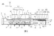
而當該可插拔模組3的插接部311完全插入該罩體1的插接空間16並與該插座連接器2對接,該可插拔模組3作用於該散熱器抬升構造6並將該移動件62的受推部622朝後推動,以使該等支撐彈簧63受到壓縮,此時該移動件62的該兩避讓部623朝後移動並避讓該兩抬升部612,也就是說,該兩抬升部612因所述彈片611的彈性變形落入呈容納孔狀的該兩避讓部623內,以使所述散熱器抬升構造6的抬升部612朝下移動至位置較低且使該散熱器4的後段得以下降的一非作用位置。在這個狀態下,該施壓構件5對該散熱器4施加的朝下的作用力,使該散熱器4連同該散熱器4的熱界面材料411d自傾斜地抬高的狀態移動至相對地水平且通過該窗口162接觸該可插拔模組3的插接部311的頂面的狀態,如圖6所示。And when the insertingportion 311 of thepluggable module 3 is fully inserted into theinsertion space 16 of thecover 1 and docked with thesocket connector 2, thepluggable module 3 acts on theradiator lifting structure 6 and The pushedpart 622 of the movingpart 62 is pushed backward, so that the supportingsprings 63 are compressed, and at this time, the two avoidingparts 623 of the movingpart 62 move backward and avoid the two liftingparts 612, that is to say The two liftingparts 612 fall into the two avoidingparts 623 in the shape of receiving holes due to the elastic deformation of theelastic piece 611, so that the liftingpart 612 of theradiator lifting structure 6 moves downward to a lower position and makes A non-active position in which the rear section of theradiator 4 is lowered. In this state, the downward force exerted by the pressingmember 5 on theheat sink 4 moves theheat sink 4 together with thethermal interface material 411d of theheat sink 4 from the obliquely elevated state to relatively horizontal and The state of contacting the top surface of thesocket part 311 of thepluggable module 3 through thewindow 162 is shown in FIG. 6 .

當該可插拔模組3的插接部311自該罩體1的插接空間16退出時,該等支撐彈簧63提供彈性復位力以朝前地推回該移動件62,此時,該散熱器抬升構造6的固定件61的推高部624沿著該推高部624的推高斜面624b滑動並回到該推高部624的頂高面624a處。在此過程中,該推高部624的推高斜面624b用以在該可插拔模組3的插接部311自該罩體1的插接空間16退出時將該固定件61的抬升部612逐漸朝上推頂。藉此,使該固定件61的抬升部612受到該移動件62的支撐而回復至將該散熱器4的後段抬升的該作用位置。When the insertingportion 311 of thepluggable module 3 withdraws from the insertingspace 16 of thehousing 1, the supportingsprings 63 provide an elastic restoring force to push back the movingmember 62 forwardly. At this time, the The push-upportion 624 of the fixingpart 61 of theradiator lifting structure 6 slides along the push-upslope 624 b of the push-upportion 624 and returns to thetop surface 624 a of the push-upportion 624 . During this process, the push-upslope 624b of the push-upportion 624 is used to lift the fixingpart 61 when the plug-inportion 311 of thepluggable module 3 withdraws from the plug-inspace 16 of thehousing 1 612 gradually pushes up the top. Thereby, the liftingpart 612 of the fixingpart 61 is supported by the movingpart 62 and returned to the active position where the rear section of theradiator 4 is lifted.

通過所述抬升部612抬高該散熱器4的後段,使該散熱器4及該散熱器4的熱界面材料411d朝後且朝上傾斜地延伸,另外,再加上該散熱器4的位於前方的該保護坡部411a之配合,能使該可插拔模組3部分地插入所述罩體1時不會直接接觸到該熱界面材料411d,並且,使該可插拔模組3能先接觸到該保護坡部411a,以避免該熱界面材料411d在該可插拔模組3的插入過程中被該可插拔模組3刮破或磨損。另外,由於該熱界面材料411d的前端延伸至該凹溝411c內,藉此能夠進一步避免該熱界面材料411d的前端在該可插拔模組3的插入過程中與該可插拔模組3接觸而產生推擠翹曲或刮破的情況。The rear section of theheat sink 4 is raised by the liftingportion 612, so that theheat sink 4 and thethermal interface material 411d of theheat sink 4 extend backward and upward obliquely. In addition, the front of theheat sink 4 The cooperation of theprotective slope 411a can prevent thepluggable module 3 from directly contacting thethermal interface material 411d when it is partially inserted into thecover 1, and thepluggable module 3 can first contact with theprotective slope portion 411a to prevent thethermal interface material 411d from being scratched or worn by thepluggable module 3 during the insertion process of thepluggable module 3 . In addition, since the front end of thethermal interface material 411d extends into thegroove 411c, it can further prevent the front end of thethermal interface material 411d from colliding with thepluggable module 3 during the insertion process of thepluggable module 3 . Pushing, warping or scratching caused by contact.

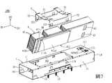
參閱圖7至圖11,本發明連接器組件100之一第二實施例與該第一實施例的不同之處在於,該移動件62具有兩個抬升部625,該散熱器4具有位於後段且對應於該兩抬升部625的兩個避讓部43,該兩抬升部625呈一體構造形成於所述移動件62的凸塊,該兩避讓部43為形成於所述散熱器4的基板41的後段的底面且用以容納所述抬升部625的凹槽。該固定件61還形成有對應於該移動件62的該兩抬升部625的兩個通孔614,該移動件62的該兩抬升部625通過該固定件61的該兩通孔614與該罩體1的該兩開孔111凸伸出該罩體1的頂壁11外。另外,所述支撐彈簧63’的數量為一個,該支撐彈簧63’呈一體構造地形成在該移動件62的後端且用以靠抵於該罩體1的後壁14的彈片結構,舉例來說,該支撐彈簧63’可以是兩端連接於該移動件62的後端。7 to 11, a second embodiment of theconnector assembly 100 of the present invention differs from the first embodiment in that the movingpart 62 has two raisedparts 625, and theradiator 4 has a Corresponding to the two avoidingparts 43 of the two liftingparts 625, the two liftingparts 625 are integrally formed on the bump of the movingpart 62, and the two avoidingparts 43 are formed on thebase plate 41 of theheat sink 4. The bottom surface of the rear section is used to accommodate the groove of the raisedportion 625 . The fixingpart 61 is also formed with two throughholes 614 corresponding to the two liftingparts 625 of the movingpart 62, and the two liftingparts 625 of the movingpart 62 pass through the two throughholes 614 of the fixingpart 61 and the cover. The twoopenings 111 of thebody 1 protrude from thetop wall 11 of thecover body 1 . In addition, the number of thesupport spring 63 ′ is one, and thesupport spring 63 ′ is integrally formed at the rear end of the movingpart 62 and used to lean against the elastic structure of therear wall 14 of thecover body 1 , for example In other words, the supportingspring 63 ′ can be connected to the rear end of the movingmember 62 at both ends.

參閱圖7、圖8、圖11及圖12,當該可插拔模組3未插入該罩體1的插接空間16,該散熱器抬升構造6的移動件62的抬升部625位於將該散熱器4的後段抬升的該作用位置,在該作用位置時,該散熱器抬升構造6的移動件62的該兩抬升部625撐頂於該散熱器4的基板41的後段,此時該散熱器4連同該散熱器4的熱界面材料411d相對於該水平基準面H朝後且朝上傾斜地延伸,進一步來說,在此狀態下該保護坡部411a的底部低於該熱界面材料411d的底部,如圖8所示。接著,當該可插拔模組3的插接部311部分地插入該罩體1的插接空間16,該可插拔模組3的插接部311的頂面接觸於位置較低的該散熱器4的保護坡部411a的底部。Referring to Fig. 7, Fig. 8, Fig. 11 and Fig. 12, when thepluggable module 3 is not inserted into theinsertion space 16 of thecover body 1, the liftingpart 625 of the movingpart 62 of theradiator lifting structure 6 is positioned on the The active position where the rear section of theradiator 4 is lifted, when in the active position, the two liftingparts 625 of the movingpart 62 of theradiator lifting structure 6 are supported against the rear section of thebase plate 41 of theradiator 4, and the heat dissipation Theheat sink 4 and thethermal interface material 411d of theheat sink 4 extend backward and upward with respect to the horizontal reference plane H. Further, in this state, the bottom of theprotective slope 411a is lower than the bottom of thethermal interface material 411d bottom, as shown in Figure 8. Next, when the insertingportion 311 of thepluggable module 3 is partially inserted into the insertingspace 16 of thehousing 1, the top surface of the insertingportion 311 of thepluggable module 3 contacts the lower position. Theradiator 4 protects the bottom of theslope portion 411a.

而當該可插拔模組3的插接部311完全插入該罩體1的插接空間16並與該插座連接器2(見圖1)對接,該可插拔模組3作用於該散熱器抬升構造6並將該移動件62的受推部622朝後推動,以使該支撐彈簧63’受到壓縮,此時該移動件62的該兩抬升部625朝後移動至被該散熱器4的該兩避讓部43避讓的該非作用位置,也就是說,呈凸塊狀的該移動件62的兩抬升部625朝後移動並落入呈凹槽狀的該散熱器4的該兩避讓部43內,以使該散熱器4的後段在該施壓構件5的作用力之下得以下降。在這個狀態下,該施壓構件5對該散熱器4施加的朝下的作用力,使該散熱器4連同該散熱器4的熱界面材料411d自傾斜地抬高的狀態移動至相對地水平且接觸該可插拔模組3的插接部311的頂面的狀態,如圖12所示。And when the insertingportion 311 of thepluggable module 3 is fully inserted into theinsertion space 16 of thehousing 1 and docked with the socket connector 2 (see FIG. 1 ), thepluggable module 3 acts on the heat dissipation Thedevice lifting structure 6 pushes the pushedpart 622 of the movingpart 62 backward, so that the support spring 63' is compressed, and at this time, the two liftingparts 625 of the movingpart 62 move backward to be supported by theradiator 4 The inactive position where the two avoidingparts 43 avoid, that is to say, the two liftingparts 625 of the movingpart 62 in the shape of a bump move backward and fall into the two avoiding parts of theradiator 4 in a groove shape. 43, so that the rear section of theradiator 4 can be lowered under the force of thepressing member 5. In this state, the downward force exerted by the pressingmember 5 on theheat sink 4 moves theheat sink 4 together with thethermal interface material 411d of theheat sink 4 from the obliquely elevated state to relatively horizontal and The state of contacting the top surface of thesocket part 311 of thepluggable module 3 is shown in FIG. 12 .

當該可插拔模組3的插接部311自該罩體1的插接空間16退出時,該支撐彈簧63’提供彈性復位力以朝前地推回該移動件62。在此過程中,呈凸塊狀的該移動件62的兩抬升部625朝前移動並自呈凹槽狀的該散熱器4的該兩避讓部43內脫出。藉此,使該移動件62的抬升部625回復至將該散熱器4的後段抬升的該作用位置。When the pluggingportion 311 of thepluggable module 3 withdraws from the pluggingspace 16 of thehousing 1, the support spring 63' provides an elastic restoring force to push back the movingmember 62 forward. During this process, the two raisedportions 625 of the movingmember 62 in the shape of bumps move forward and escape from the two avoidingportions 43 of theradiator 4 in the shape of grooves. Thereby, the liftingportion 625 of the movingmember 62 returns to the active position where the rear section of theradiator 4 is lifted.

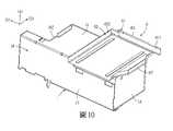
參閱圖13至圖16,本發明連接器組件100之一第三實施例與該第二實施例的不同之處在於,所述移動件62’的數量為兩個且所述移動件62’是沿該前後方向D1延伸形成,該兩移動件62’可前後滑動地設置於該散熱器4的後段的左右兩側且位於該罩體1外,該散熱器4的後端的左右兩側處分別形成有沿該上下方向D2貫穿且沿該前後方向D1延伸的兩個滑槽44,每一移動件62’的後端形成有可滑動地穿設於對應的滑槽44的一滑塊626,藉此使該兩移動件62’可相對於該散熱器4與該罩體1前後地移動,另外,每一移動件62’的受推部622自該罩體1的頂壁11的窗口162朝下地伸入該插接空間16。每一移動件62’具有一抬升部625,該散熱器4具有位於後段且對應於該兩移動件62’的抬升部625的兩個避讓部43。該兩抬升部625呈一體構造形成於所述移動件62’的凸塊,該兩避讓部43為形成於所述散熱器4的後段且用以容納所述抬升部625的凹槽。另外,所述支撐彈簧63的數量為兩個,該兩支撐彈簧63是設置在對應的移動件62’的滑塊626的末端與該散熱器4之間的圈狀彈簧。另外,該散熱器4的散熱鰭片42是一體地構造形成於該基板41,但不以此為限。13 to 16, a third embodiment of theconnector assembly 100 of the present invention differs from the second embodiment in that the number of the moving parts 62' is two and the moving parts 62' are Extending along the front-rear direction D1, the two moving parts 62' are slidably arranged on the left and right sides of the rear section of theradiator 4 and are located outside thecover body 1. The left and right sides of the rear end of theradiator 4 are respectively There are twoslide slots 44 penetrating along the up-down direction D2 and extending along the front-back direction D1. Aslider 626 is formed at the rear end of each moving member 62' to slide through thecorresponding slide slots 44. In this way, the two moving parts 62' can move back and forth relative to theradiator 4 and thecover body 1. In addition, the pushedpart 622 of each moving part 62' can pass through thewindow 162 of thetop wall 11 of thecover body 1. Projects downwards into the plug-inspace 16 . Each moving part 62' has a raisedpart 625, and theradiator 4 has twoescape parts 43 located in the rear section corresponding to the raisedparts 625 of the two moving parts 62'. The two liftingparts 625 are integrally formed on the protrusions of the moving part 62', and the two avoidingparts 43 are grooves formed on the rear section of theradiator 4 for accommodating the liftingparts 625. In addition, the number of the supportingsprings 63 is two, and the two supportingsprings 63 are coil springs arranged between the end of theslider 626 of the corresponding moving member 62' and theradiator 4. In addition, theheat dissipation fins 42 of theheat sink 4 are integrally formed on thesubstrate 41 , but not limited thereto.

參閱圖16至圖19,當該可插拔模組3未插入該罩體1的插接空間16,該散熱器抬升構造6的移動件62’的抬升部625位於將該散熱器4的後段抬升的該作用位置,在該作用位置時,該散熱器抬升構造6的該兩移動件62’的抬升部625撐頂於該散熱器4的後段,此時該散熱器4連同該散熱器4的熱界面材料411d相對於該水平基準面H朝後且朝上傾斜地延伸,進一步來說,在此狀態下該保護坡部411a的底部低於該熱界面材料411d的底部,如圖16及圖17所示。接著,當該可插拔模組3的插接部311部分地插入該罩體1的插接空間16,該可插拔模組3的插接部311的頂面接觸於位置較低的該散熱器4的保護坡部411a的底部。Referring to FIG. 16 to FIG. 19 , when thepluggable module 3 is not inserted into theinsertion space 16 of thecover body 1 , the liftingportion 625 of the movingpart 62 ′ of theradiator lifting structure 6 is located at the rear section of theradiator 4 The function position of the lift, when in the function position, the liftingparts 625 of the two moving parts 62' of theradiator lifting structure 6 support the rear section of theradiator 4. At this time, theradiator 4 together with theradiator 4 Thethermal interface material 411d extends backward and upward with respect to the horizontal reference plane H. Further, in this state, the bottom of theprotective slope 411a is lower than the bottom of thethermal interface material 411d, as shown in FIG. 16 and 17. Next, when the insertingportion 311 of thepluggable module 3 is partially inserted into the insertingspace 16 of thehousing 1, the top surface of the insertingportion 311 of thepluggable module 3 contacts the lower position. Theradiator 4 protects the bottom of theslope portion 411a.

而當該可插拔模組3的插接部311完全插入該罩體1的插接空間16並與該插座連接器2(見圖1)對接,該可插拔模組3作用於該散熱器抬升構造6並將該兩移動件62’的受推部622朝後推動,以使該支撐彈簧63受到拉伸,此時該兩移動件62’的該抬升部625朝後移動至被該散熱器4的該兩避讓部43避讓的該非作用位置,也就是說,呈凸塊狀的該兩移動件62’的抬升部625朝後移動並落入呈凹槽狀的該散熱器4的該兩避讓部43內,以使該散熱器4的後段在該施壓構件的作用力之下得以下降。在這個狀態下,該施壓構件5對該散熱器4施加的朝下的作用力,使該散熱器4連同該散熱器4的熱界面材料411d自傾斜地抬高的狀態移動至相對地水平且接觸該可插拔模組3的插接部311的頂面的狀態,如圖18及圖19所示。And when the insertingportion 311 of thepluggable module 3 is fully inserted into theinsertion space 16 of thehousing 1 and docked with the socket connector 2 (see FIG. 1 ), thepluggable module 3 acts on the heat dissipation The liftingstructure 6 of the device pushes the pushedparts 622 of the two moving parts 62' backward, so that thesupport spring 63 is stretched, and at this time, the liftingparts 625 of the two moving parts 62' move backward to be supported by the The inactive position where the two avoidingportions 43 of theradiator 4 are avoided, that is to say, the raisedportions 625 of the two movingparts 62 ′ in the shape of bumps move backward and fall into the groove-shaped portion of theradiator 4 . The twoavoidance portions 43 allow the rear section of theradiator 4 to descend under the force of the pressing member. In this state, the downward force exerted by the pressingmember 5 on theheat sink 4 moves theheat sink 4 together with thethermal interface material 411d of theheat sink 4 from the obliquely elevated state to relatively horizontal and The state of contacting the top surface of thesocket part 311 of thepluggable module 3 is shown in FIG. 18 and FIG. 19 .

當該可插拔模組3的插接部311自該罩體1的插接空間16退出時,該支撐彈簧63提供彈性復位力以朝前地推回該兩移動件62’。在此過程中,呈凸塊狀的該兩移動件62’的抬升部625朝前移動並自呈凹槽狀的該散熱器4的該兩避讓部43內脫出。藉此,使該移動件62’的抬升部625回復至將該散熱器4的後段抬升的該作用位置。When theinsertion portion 311 of thepluggable module 3 withdraws from theinsertion space 16 of thehousing 1, thesupport spring 63 provides elastic restoring force to push back the two moving parts 62' forward. During this process, the raisedparts 625 of the two moving parts 62' in the shape of bumps move forward and escape from the twoescape parts 43 of theradiator 4 in the shape of grooves. Thereby, the liftingportion 625 of the moving member 62' returns to the active position where the rear section of theradiator 4 is lifted.

綜上所述,本發明連接器組件100通過所述抬升部612(625)抬高所述散熱器4的後段,使所述散熱器4及所述散熱器4的熱界面材料411d朝後且朝上傾斜地延伸,另外,再加上所述散熱器4的位於前方的所述保護坡部411a之配合,能使所述可插拔模組3部分地插入所述罩體1時不會直接接觸到所述熱界面材料411d,並且,使所述可插拔模組3能先接觸到所述保護坡部411a,以避免所述熱界面材料411d在所述可插拔模組3的插入過程中被所述可插拔模組3刮破或磨損。In summary, theconnector assembly 100 of the present invention raises the rear section of theheat sink 4 through the lifting portion 612 (625), so that theheat sink 4 and thethermal interface material 411d of theheat sink 4 face backward and Extending obliquely upwards, in addition, coupled with the cooperation of theprotective slope 411a located in front of theradiator 4, thepluggable module 3 will not be directly inserted into thecover 1 when it is partially inserted. contact with thethermal interface material 411d, and enable thepluggable module 3 to contact theprotective slope 411a first, so as to avoid the insertion of thethermal interface material 411d in thepluggable module 3 It is scratched or worn by thepluggable module 3 during the process.

惟以上所述者,僅為本發明之實施例而已,當不能以此限定本發明實施之範圍,凡是依本發明申請專利範圍及專利說明書內容所作之簡單的等效變化與修飾,皆仍屬本發明專利涵蓋之範圍內。But what is described above is only an embodiment of the present invention, and should not limit the scope of the present invention. All simple equivalent changes and modifications made according to the patent scope of the present invention and the content of the patent specification are still within the scope of the present invention. Within the scope covered by the patent of the present invention.

100:連接器組件1:罩體11:頂壁111:開孔12:底壁13:側壁131:扣接凸塊132:卡塊14:後壁15:插腳16:插接空間161:前端插口162:窗口163:底部開口17:接地件171:彈性指部2:插座連接器21:座體211:插接槽22:端子3:可插拔模組31:殼體311:插接部32:插接板321:接觸指部4:散熱器41:基板411:熱耦合結構411a:保護坡部411b:熱耦合部411c:凹溝411d:熱界面材料42:散熱鰭片43:避讓部44:滑槽5:施壓構件51:彈性壓抵部52:組裝部521:扣接孔6:散熱器抬升構造61:固定件611:彈片612:抬升部613:軌槽614:通孔62:移動件62’:移動件621:軌條622:受推部623:避讓部624:推高部624a:頂高面624b:推高斜面625:抬升部626:滑塊63:支撐彈簧63’:支撐彈簧64:彈簧支撐桿D1:前後方向D2:上下方向D3:左右方向H:水平基準面100:Connector assembly1: Cover body11: top wall111: opening12: Bottom wall13: side wall131: Buckle projection132: block14: rear wall15: Pin16: Insertion space161: front socket162: window163: Bottom opening17: Grounding piece171: elastic fingers2: socket connector21: seat body211: socket slot22: terminal3: Pluggable modules31: Shell311: socket part32: plug board321: contact fingers4: Radiator41: Substrate411: thermal coupling structure411a: protect the slope411b: thermal coupling part411c: concave groove411d: Thermal Interface Materials42: cooling fins43: Avoidance department44: Chute5: Pressure member51: elastic pressing part52:Assembly Department521: button hole6: radiator lifting structure61:Fixer611: shrapnel612: lifting part613: rail groove614: Through hole62: Moving parts62': moving parts621: rail622: Pushed Department623: Avoidance Department624: push up the department624a: top surface624b: Push up the ramp625: lifting part626:Slider63: support spring63': support spring64: spring support rodD1: Front and rear directionsD2: up and down directionD3: left and right directionsH: horizontal datum

本發明之其他的特徵及功效,將於參照圖式的實施方式中清楚地呈現,其中: 圖1是本發明連接器組件的一第一實施例的一立體分解圖; 圖2是該第一實施例的一剖視圖; 圖3是該第一實施例的罩體與散熱器抬升構造的一局部剖切立體圖; 圖4是圖3中的該第一實施例的罩體與散熱器抬升構造以另一視角觀看的一局部剖切立體圖; 圖5是該第一實施例的罩體與散熱器抬升構造的一局部剖切立體分解圖; 圖6是該第一實施例的一剖視圖,圖中該第一實施例的可插拔模組插入罩體; 圖7是本發明連接器組件的一第二實施例的一立體分解圖,圖中該第二實施例的散熱器的底部略為朝上翻轉; 圖8是該第二實施例的一剖視圖; 圖9是該第二實施例的罩體與散熱器抬升構造的一局部剖切立體分解圖; 圖10是圖9中的該第二實施例的罩體與散熱器抬升構造以另一視角觀看的一局部剖切立體圖; 圖11是該第二實施例的散熱器抬升構造的一立體分解圖; 圖12是該第二實施例的一剖視圖,圖中該第二實施例的可插拔模組插入罩體; 圖13是本發明連接器組件的一第三實施例的一立體圖; 圖14是該第三實施例的一立體分解圖; 圖15是圖14中的該第三實施例以另一視角觀看的一立體分解圖; 圖16是該第三實施例的一局部剖切立體圖; 圖17是該第三實施例的一局部剖視圖; 圖18是該第三實施例的一局部剖切立體圖,圖中該第三實施例的可插拔模組插入罩體;以及 圖19是該第三實施例的一局部剖視圖,圖中該第三實施例的可插拔模組插入罩體。Other features and effects of the present invention will be clearly presented in the implementation manner with reference to the drawings, wherein: Fig. 1 is a three-dimensional exploded view of a first embodiment of the connector assembly of the present invention; Fig. 2 is a sectional view of the first embodiment; Fig. 3 is a partial cutaway perspective view of the cover body and radiator lifting structure of the first embodiment; Fig. 4 is a partially cutaway perspective view of the cover body and radiator lifting structure of the first embodiment in Fig. 3 viewed from another angle; Fig. 5 is a partial cutaway perspective exploded view of the cover body and radiator lifting structure of the first embodiment; Fig. 6 is a sectional view of the first embodiment, in which the pluggable module of the first embodiment is inserted into the cover; Fig. 7 is a three-dimensional exploded view of a second embodiment of the connector assembly of the present invention, in which the bottom of the heat sink of the second embodiment is slightly turned upward; Fig. 8 is a sectional view of the second embodiment; Fig. 9 is a partial cutaway perspective exploded view of the cover body and radiator lifting structure of the second embodiment; Fig. 10 is a partially cut-away perspective view of the second embodiment of the cover body and the radiator lifting structure viewed from another angle in Fig. 9; Fig. 11 is a three-dimensional exploded view of the radiator lifting structure of the second embodiment; Fig. 12 is a sectional view of the second embodiment, in which the pluggable module of the second embodiment is inserted into the cover; 13 is a perspective view of a third embodiment of the connector assembly of the present invention; Fig. 14 is a three-dimensional exploded view of the third embodiment; Fig. 15 is a three-dimensional exploded view of the third embodiment in Fig. 14 viewed from another viewing angle; Fig. 16 is a partial cutaway perspective view of the third embodiment; Fig. 17 is a partial sectional view of the third embodiment; Fig. 18 is a partial cutaway perspective view of the third embodiment, in which the pluggable module of the third embodiment is inserted into the cover; and FIG. 19 is a partial sectional view of the third embodiment, in which the pluggable module of the third embodiment is inserted into the cover.

100:連接器組件100:Connector assembly

1:罩體1: Cover body

11:頂壁11: top wall

111:開孔111: opening

12:底壁12: Bottom wall

13:側壁13: side wall

14:後壁14: rear wall

15:插腳15: Pin

16:插接空間16: Insertion space

161:前端插口161: front socket

162:窗口162: window

163:底部開口163: Bottom opening

17:接地件17: Grounding piece

171:彈性指部171: elastic fingers

2:插座連接器2: socket connector

21:座體21: seat body

211:插接槽211: socket slot

22:端子22: terminal

4:散熱器4: Radiator

41:基板41: Substrate

411:熱耦合結構411: thermal coupling structure

411a:保護坡部411a: protect the slope

411b:熱耦合部411b: thermal coupling part

411c:凹溝411c: concave groove

411d:熱界面材料411d: Thermal Interface Materials

42:散熱鰭片42: cooling fins

5:施壓構件5: Pressure member

51:彈性壓抵部51: elastic pressing part

6:散熱器抬升構造6: radiator lifting structure

61:固定件61:Fixer

611:彈片611: shrapnel

612:抬升部612: lifting part

62:移動件62: Moving parts

622:受推部622: Pushed Department

623:避讓部623: Avoidance department

624:推高部624: push up the department

624a:頂高面624a: top surface

624b:推高斜面624b: Push up the ramp

63:支撐彈簧63: support spring

64:彈簧支撐桿64: spring support rod

D1:前後方向D1: Front and rear directions

D2:上下方向D2: up and down direction

D3:左右方向D3: left and right directions

H:水平基準面H: horizontal datum

Claims (12)

Translated fromChinese
一種連接器組件,包含: 罩體,具有位於內部的插接空間,以及構成所述插接空間的頂壁,所述頂壁具有窗口; 插座連接器,設於所述罩體的插接空間內; 可插拔模組,用以插入所述罩體的插接空間以與所述插座連接器對接; 散熱器,具有向下凸伸的熱耦合結構,所述熱耦合結構具有位於前方的保護坡部、位於所述保護坡部後方的熱耦合部,以及設於所述熱耦合部的底面的熱界面材料; 施壓構件,組裝所述散熱器至所述罩體的頂壁,並對所述散熱器施加朝下的作用力;以及 散熱器抬升構造,具有位於所述施壓構件的後方且用以推頂所述散熱器的後段處的抬升部; 當所述可插拔模組未插入所述罩體的插接空間,所述散熱器抬升構造的抬升部位於將所述散熱器的後段抬升的作用位置,此時所述熱界面材料朝後且朝上傾斜地延伸;當所述可插拔模組插入所述罩體的插接空間並與所述插座連接器對接,所述可插拔模組作用於所述散熱器抬升構造,以使所述散熱器抬升構造的抬升部移動至使所述散熱器的後段下降的非作用位置, 此時所述施壓構件對所述散熱器施加的作用力,使所述熱界面材料自傾斜地抬高的狀態移動至相對地水平且通過所述窗口接觸所述可插拔模組的狀態。A connector assembly comprising: The cover body has a plugging space located inside, and a top wall constituting the plugging space, the top wall has a window; The socket connector is arranged in the insertion space of the cover body; a pluggable module, used for inserting into the insertion space of the housing to connect with the socket connector; The heat sink has a downwardly protruding thermal coupling structure, and the thermal coupling structure has a protective slope portion located in front, a thermal coupling portion located behind the protective slope portion, and a heat sink provided on the bottom surface of the thermal coupling portion. interface material; a pressing member for assembling the radiator to the top wall of the housing and exerting a downward force on the radiator; and a radiator lifting structure having a raised portion at the rear of the pressing member for pushing up the rear section of the radiator; When the pluggable module is not inserted into the insertion space of the cover body, the lifting part of the radiator lifting structure is located at the active position of lifting the rear section of the radiator, and at this time, the thermal interface material faces backward And extend upwards obliquely; when the pluggable module is inserted into the insertion space of the cover and docked with the socket connector, the pluggable module acts on the lifting structure of the radiator, so that The lifting part of the radiator lifting structure moves to the inactive position where the rear section of the radiator is lowered. At this time, the force exerted by the pressing member on the radiator makes the thermal interface material self-obliquely lift. The high state moves to a state that is relatively horizontal and contacts the pluggable module through the window.如請求項1所述的連接器組件,其中,當所述散熱器抬升構造的抬升部位於所述作用位置且所述散熱器的後段被抬升時,所述保護坡部的底部低於所述熱界面材料的底部。The connector assembly according to claim 1, wherein when the lifting portion of the radiator lifting structure is in the active position and the rear section of the radiator is lifted, the bottom of the protection slope is lower than the bottom of the thermal interface material.如請求項2所述的連接器組件,其中,所述熱耦合結構於所述保護坡部與所述熱耦合部之間形成有一凹溝,所述熱界面材料的前端延伸至所述凹溝內。The connector assembly according to claim 2, wherein the thermal coupling structure forms a concave groove between the protection slope portion and the thermal coupling portion, and the front end of the thermal interface material extends to the concave groove Inside.如請求項1至請求項3中任一項所述的連接器組件,其中,所述散熱器抬升構造設置在所述罩體內且位於所述頂壁下方,所述散熱器抬升構造包括固定件、移動件及支撐彈簧;所述固定件組裝於所述罩體,所述固定件具有朝後延伸的彈片,以及設置於所述彈片末端的所述抬升部;所述移動件可相對所述固定件前後移動地設置於所述固定件,所述移動件具有對應於所述抬升部的避讓部;所述支撐彈簧設置於所述移動件並提供給所述移動件彈性復位力;當所述可插拔模組未插入所述罩體的插接空間,所述固定件的抬升部受到所述移動件的支撐而位於所述作用位置;當所述可插拔模組插入所述罩體的插接空間並與所述插座連接器對接,所述可插拔模組推動所述移動件,使所述移動件的避讓部朝後移動並避讓所述抬升部,以使所述固定件的抬升部移動至使所述非作用位置;當所述可插拔模組自所述罩體的插接空間退出,所述支撐彈簧提供彈性復位力以朝前地推回所述移動件,以使所述固定件的抬升部受到所述移動件的支撐而回復至所述作用位置。The connector assembly according to any one of claim 1 to claim 3, wherein the radiator lifting structure is disposed in the housing and below the top wall, and the radiator lifting structure includes a fixing member , a moving part and a supporting spring; the fixing part is assembled on the cover body, the fixing part has an elastic piece extending backward, and the lifting part is arranged at the end of the elastic piece; the moving part can be opposite to the The fixed part is arranged on the fixed part to move back and forth, and the moving part has an avoidance part corresponding to the lifting part; the support spring is arranged on the moving part and provides an elastic reset force to the moving part; when the moving part The pluggable module is not inserted into the insertion space of the cover body, the lifting part of the fixing part is supported by the moving part and is located at the active position; when the pluggable module is inserted into the cover The plugging space of the body and docking with the socket connector, the pluggable module pushes the moving part, so that the avoiding part of the moving part moves backward and avoids the lifting part, so that the fixed The lifting part of the part moves to the inactive position; when the pluggable module withdraws from the insertion space of the cover body, the supporting spring provides an elastic restoring force to push back the moving part forward , so that the lifting part of the fixing part is supported by the moving part and returns to the active position.如請求項4所述的連接器組件,其中,所述抬升部是一體構造形成於所述彈片末端且朝上翻折的捲曲片體,所述避讓部為形成於所述移動件且用以容納所述抬升部的容納孔,所述移動件還具有位於所述避讓部的後端的推高部,所述推高部具有朝向上方的頂高面,以及自所述頂高面的前緣朝前並朝下傾斜地延伸的推高斜面,所述頂高面用以在所述可插拔模組未插入所述罩體的插接空間時支撐所述固定件的抬升部至所述作用位置,所述推高斜面用以在所述可插拔模組自所述罩體的插接空間退出時將所述固定件的抬升部逐漸朝上推頂。The connector assembly according to claim 4, wherein, the lifting part is a curled piece integrally formed at the end of the elastic piece and turned upwards, and the avoiding part is formed on the moving part for The accommodating hole for accommodating the lifting part, the moving part also has a push-up part located at the rear end of the avoidance part, the push-up part has a top surface facing upwards, and a front edge from the top surface a push-up inclined surface extending obliquely forward and downward, the top surface is used to support the lifting part of the fixing part to the function when the pluggable module is not inserted into the insertion space of the cover body position, the push-up slope is used to gradually push the lifting part of the fixing part upward when the pluggable module withdraws from the insertion space of the cover.如請求項5所述的連接器組件,其中,所述支撐彈簧是設置在所述移動件與所述固定件之間的圈狀彈簧。The connector assembly according to claim 5, wherein the supporting spring is a coil spring arranged between the moving part and the fixing part.如請求項1至請求項3中任一項所述的連接器組件,其中,所述散熱器抬升構造設置在所述罩體內且位於所述頂壁下方,所述散熱器抬升構造包括固定件、移動件及支撐彈簧;所述固定件組裝於所述罩體;所述移動件可相對所述固定件前後移動地設置於所述固定件,所述移動件具有所述抬升部,所述散熱器具有對應於所述抬升部的避讓部;所述支撐彈簧設置於所述移動件並提供給所述移動件彈性復位力;當所述可插拔模組未插入所述罩體的插接空間,所述移動件的抬升部位於所述作用位置;當所述可插拔模組插入所述罩體的插接空間並與所述插座連接器對接,所述可插拔模組推動所述移動件,使所述移動件的抬升部朝後移動至被所述散熱器的避讓部避讓的所述非作用位置;當所述可插拔模組自所述罩體的插接空間退出,所述支撐彈簧提供彈性復位力以朝前地推回所述移動件,以使所述移動件的抬升部朝前移動以回復至所述作用位置。The connector assembly according to any one of claim 1 to claim 3, wherein the radiator lifting structure is disposed in the housing and below the top wall, and the radiator lifting structure includes a fixing member , a moving piece and a supporting spring; the fixing piece is assembled on the cover body; the moving piece is arranged on the fixing piece so that it can move back and forth relative to the fixing piece, the moving piece has the lifting portion, the The radiator has an avoidance portion corresponding to the lifting portion; the support spring is arranged on the moving part and provides an elastic restoring force to the moving part; when the pluggable module is not inserted into the plug of the cover, The lifting part of the moving part is located at the active position; when the pluggable module is inserted into the plugging space of the cover and docked with the socket connector, the pluggable module pushes The moving part makes the lifting part of the moving part move backward to the inactive position avoided by the avoiding part of the radiator; When withdrawing, the support spring provides an elastic restoring force to push back the moving part forward, so that the lifting part of the moving part moves forward to return to the active position.如請求項7所述的連接器組件,其中,所述抬升部呈一體構造形成於所述移動件的凸塊,所述避讓部為形成於所述散熱器且用以容納所述抬升部的凹槽。The connector assembly according to claim 7, wherein, the lifting part is integrally formed on the protrusion of the moving part, and the avoiding part is formed on the heat sink and is used to accommodate the lifting part groove.如請求項8所述的連接器組件,其中,所述支撐彈簧是一體構造地形成在所述移動件的彈片結構。The connector assembly as claimed in claim 8, wherein the supporting spring is an elastic piece integrally formed on the moving part.如請求項1至請求項3中任一項所述的連接器組件,其中,所述散熱器抬升構造包括移動件及支撐彈簧;所述移動件設置於所述散熱器的後段且位於所述罩體外,所述移動件可相對所述散熱器前後移動地通過所述支撐彈簧連接於所述散熱器,所述移動件具有所述抬升部,所述散熱器具有對應於所述抬升部的避讓部;所述支撐彈簧提供給所述移動件彈性復位力;當所述可插拔模組未插入所述罩體的插接空間,所述移動件的抬升部位於所述作用位置;當所述可插拔模組插入所述罩體的插接空間並與所述插座連接器對接,所述可插拔模組推動所述移動件,使所述移動件的抬升部朝後移動至被所述散熱器的避讓部避讓的所述非作用位置;當所述可插拔模組自所述罩體的插接空間退出,所述支撐彈簧提供彈性復位力以朝前地推回所述移動件,以使所述移動件的抬升部朝前移動以回復至所述作用位置。The connector assembly according to any one of claim 1 to claim 3, wherein the radiator lifting structure includes a moving part and a supporting spring; the moving part is arranged at the rear section of the radiator and is located at the Outside the cover, the moving part is connected to the radiator through the supporting spring so that it can move back and forth relative to the radiator, the moving part has the lifting part, and the radiator has a corresponding to the lifting part. avoidance part; the support spring provides elastic return force to the moving part; when the pluggable module is not inserted into the insertion space of the cover, the lifting part of the moving part is at the active position; when The pluggable module is inserted into the insertion space of the cover and docked with the socket connector, the pluggable module pushes the moving part, and the lifting part of the moving part moves backward to The non-active position is avoided by the avoiding part of the heat sink; when the pluggable module withdraws from the insertion space of the cover, the supporting spring provides an elastic restoring force to push back the plugging module forwardly. the moving part, so that the lifting part of the moving part moves forward to return to the active position.如請求項10所述的連接器組件,其中,所述抬升部呈一體構造形成於所述移動件的凸塊,所述避讓部為形成於所述散熱器且用以容納所述抬升部的凹槽。The connector assembly according to claim 10, wherein the lifting part is integrally formed on the protrusion of the moving part, and the avoiding part is formed on the heat sink and is used to accommodate the lifting part groove.如請求項11所述的連接器組件,其中,所述支撐彈簧是設置在所述移動件與所述散熱器之間的圈狀彈簧。The connector assembly as claimed in claim 11, wherein the supporting spring is a coil spring arranged between the moving member and the heat sink.
TW110109993A2021-03-192021-03-19 connector assemblyTWI763384B (en)

Priority Applications (1)

Application NumberPriority DateFiling DateTitle
TW110109993ATWI763384B (en)2021-03-192021-03-19 connector assembly

Applications Claiming Priority (1)

Application NumberPriority DateFiling DateTitle
TW110109993ATWI763384B (en)2021-03-192021-03-19 connector assembly

Publications (2)

Publication NumberPublication Date
TWI763384B TWI763384B (en)2022-05-01
TW202239085Atrue TW202239085A (en)2022-10-01

Family

ID=82594116

Family Applications (1)

Application NumberTitlePriority DateFiling Date
TW110109993ATWI763384B (en)2021-03-192021-03-19 connector assembly

Country Status (1)

CountryLink
TW (1)TWI763384B (en)

Families Citing this family (2)

* Cited by examiner, † Cited by third party
Publication numberPriority datePublication dateAssigneeTitle
TWI835215B (en)*2022-07-222024-03-11台灣莫仕股份有限公司 Connector components
TWI821021B (en)*2022-11-162023-11-01台灣莫仕股份有限公司 Connector components

Family Cites Families (5)

* Cited by examiner, † Cited by third party
Publication numberPriority datePublication dateAssigneeTitle
TWM542267U (en)*2015-08-182017-05-21Molex LlcConnector system
US10295767B2 (en)*2017-07-202019-05-21Quanta Computer Inc.Spoiler heat sink device in belly-to-belly transceiver
CN210404248U (en)*2019-04-082020-04-24莫列斯有限公司Electrical connection device
TWI708442B (en)*2019-07-122020-10-21台灣莫仕股份有限公司 Connector assembly
TWM596469U (en)*2019-12-122020-06-01台灣莫仕股份有限公司Connector assembly

Also Published As

Publication numberPublication date
TWI763384B (en)2022-05-01

Similar Documents

PublicationPublication DateTitle
CN108738278B (en)Heat sink for electrical connector assembly
US10547133B1 (en)Vertical communication system
CN205081293U (en)Socket subassembly and transceiver module subassembly
CN114623722A (en)Connector assembly
CN110783741B (en)Card edge connector with contact locator
TWI757113B (en) connector assembly
TW202239085A (en)Connector assembly that comprises a hood, a receptacle connector, an insertion and removal module, a heat dissipater, and a heat dissipater lifting structure
TWI833050B (en)Socket connector and cable assembly for a communication system
TWI753695B (en) connector assembly
US20060148318A1 (en)Electrical card connector
CN114204317A (en)Heat exchange assembly for pluggable module
JP6045953B2 (en) connector
US9743556B1 (en)Electrical connector structure
EP3166183B1 (en)Connector cover and connector assembly
US7040907B2 (en)Electric plug
TW201330389A (en)Electrical connector, electronic apparatus using the same and metod for assembling the electrical connector
TWI819887B (en) Connector components
CN115117707B (en) Connector components
US20040175986A1 (en)Land grid array connector assembly with mounting base
JP2021093242A (en)Connector for card
CN114447650B (en) Connector components
TWI816488B (en) Connector components
TWI832697B (en) Connector components
TWI892577B (en) Connector assembly
US20240364056A1 (en)Connector assembly

[8]ページ先頭

©2009-2025 Movatter.jp