Movatterモバイル変換


[0]ホーム

URL:


TW202230413A - Luminous keyboard and optical module thereof - Google Patents

Luminous keyboard and optical module thereof
Download PDF

Info

Publication number
TW202230413A
TW202230413ATW110103600ATW110103600ATW202230413ATW 202230413 ATW202230413 ATW 202230413ATW 110103600 ATW110103600 ATW 110103600ATW 110103600 ATW110103600 ATW 110103600ATW 202230413 ATW202230413 ATW 202230413A
Authority
TW
Taiwan
Prior art keywords
light
area
shielding
sub
transmitting
Prior art date
Application number
TW110103600A
Other languages
Chinese (zh)
Other versions
TWI765552B (en
Inventor
陳兆俞
Original Assignee
達方電子股份有限公司
Priority date (The priority date is an assumption and is not a legal conclusion. Google has not performed a legal analysis and makes no representation as to the accuracy of the date listed.)
Filing date
Publication date
Application filed by 達方電子股份有限公司filedCritical達方電子股份有限公司
Priority to TW110103600ApriorityCriticalpatent/TWI765552B/en
Priority to US17/585,714prioritypatent/US11520101B2/en
Priority to US17/585,699prioritypatent/US11852861B2/en
Application grantedgrantedCritical
Publication of TWI765552BpublicationCriticalpatent/TWI765552B/en
Publication of TW202230413ApublicationCriticalpatent/TW202230413A/en

Links

Images

Landscapes

Abstract

A luminous keyboard and an optical module thereof are provided. The optical module includes a light guide plate, a reflective film, and an optical film. The reflective film is disposed at one side of the light guide plate, and the optical film is disposed at another side of the light guide plate opposite to the reflective film. The optical film has a mask pattern defining a light-transparent region, a light-shielding region, and a light modulation region extending from the light-shielding region to the light-transparent region, wherein: the light-transparent region allows light to transmit therethrough, the light-shielding region blocks light, and the light modulation region partially allows light to transmit therethrough and partially blocks light, so that an average light transmittance per unit area of the light modulation region is smaller than that of the light-transparent region and larger than that of the light-shielding region.

Description

Translated fromChinese
發光鍵盤及其光學模組Illuminated keyboard and optical module thereof

本發明一般係關於一種發光鍵盤及其光學模組,具體而言,本發明係關於一種適用於調變按鍵亮度的發光鍵盤及其光學模組。The present invention generally relates to a light-emitting keyboard and an optical module thereof, and in particular, the present invention relates to a light-emitting keyboard and an optical module thereof suitable for modulating the brightness of keys.

鍵盤為電子產品(尤其是電腦)非常重要的輸入裝置。隨著電子產品的微型化及輕巧化,窄邊框設計為現今鍵盤重要的研發方向之一。然而,以發光鍵盤而言,須考慮到按鍵模組與背光模組的整合,尤其是要考慮到背光模組的多層光學膜片之間的黏合及避免側漏光等問題,使得外側按鍵與內側按鍵的發光均勻性不易控制。尤其是,在窄邊框設計上,隨著邊緣餘裕縮小,發光鍵盤容易發生外側按鍵偏亮或偏暗的問題。Keyboards are very important input devices for electronic products (especially computers). With the miniaturization and lightness of electronic products, narrow bezel design is one of the important research and development directions of keyboards today. However, in the case of an illuminated keyboard, the integration of the key module and the backlight module must be considered, especially the adhesion between the multilayer optical films of the backlight module and the avoidance of side light leakage. The uniformity of light emission of the keys is not easy to control. In particular, in the design of narrow bezels, as the edge margin is reduced, the problem of brighter or darker outer keys is prone to occur on the illuminated keyboard.

再者,一般為了散熱或是定位設計,背光模組通常需要開設貫孔,以供氣流或供定位機構(例如定位柱、螺絲等)通過,使得貫孔附近的按鍵相對於其他按鍵偏亮或偏暗的問題。此外,接近背光模組之光源的按鍵也可能會有局部偏亮或偏暗的問題。Furthermore, generally for heat dissipation or positioning design, the backlight module usually needs to open through holes for airflow or for positioning mechanisms (such as positioning posts, screws, etc.) to pass through, so that the keys near the through holes are brighter or brighter than other keys. dark issue. In addition, the buttons close to the light source of the backlight module may also be partially bright or dark.

本發明之一目的在於提供一種發光鍵盤及其光學模組,其藉由光學膜片的遮光圖案設計,可調變外側按鍵、鄰近孔洞按鍵、及/或鄰近光源按鍵的亮度,進而提升按鍵發光的均勻性。One object of the present invention is to provide a light-emitting keyboard and an optical module thereof, which can adjust the brightness of the outer keys, the keys adjacent to the holes, and/or the keys adjacent to the light source through the design of the shading pattern of the optical film, thereby improving the light emission of the keys. uniformity.

於一實施例,本發明提供一種適用於發光鍵盤之光學模組,其包含導光板、反射片及光學膜片,其中反射片設置於導光板之一側,且光學膜片相對於反射片設置於導光板之另一側;光學膜片具有遮光圖案,遮光圖案定義透光區、遮光區及光量調變區,且光量調變區自遮光區延伸至透光區,其中:透光區容許光線通過,遮光區阻擋光線,並且光量調變區局部容許光線通過且局部阻擋光線,使得光量調變區的單位面積平均光透射率小於透光區且大於遮光區。In one embodiment, the present invention provides an optical module suitable for a light-emitting keyboard, which includes a light guide plate, a reflection sheet and an optical film, wherein the reflection sheet is disposed on one side of the light guide plate, and the optical film is disposed relative to the reflection sheet On the other side of the light guide plate; the optical film has a light-shielding pattern, the light-shielding pattern defines a light-transmitting area, a light-shielding area and a light-quantity modulating area, and the light-quantity modulating area extends from the shading area to the light-transmitting area, wherein: the light-transmitting area allows When the light passes through, the shading area blocks the light, and the light quantity modulation area partially allows the light to pass through and partially blocks the light, so that the average light transmittance per unit area of the light quantity modulation area is smaller than the light transmission area and greater than the shading area.

於一實施例,光量調變區包含複數子遮光區及複數子透光區,且複數子遮光區及複數子透光區交錯設置。In one embodiment, the light quantity modulation region includes a plurality of sub-light-shielding regions and a plurality of sub-light-transmitting regions, and the plurality of sub-light-shielding regions and the plurality of sub-light-transmitting regions are alternately arranged.

於一實施例,複數子遮光區各具有相對的第一端及第二端,第一端連接遮光區,且第二端延伸至透光區。In one embodiment, each of the plurality of sub light-shielding regions has opposite first ends and second ends, the first end is connected to the light-shielding region, and the second end extends to the light-transmitting region.

於一實施例,第一端的寬度大於或等於第二端的寬度,且當第一端的寬度大於第二端的寬度時,子遮光區的寬度自遮光區朝透光區逐漸縮減。In one embodiment, the width of the first end is greater than or equal to the width of the second end, and when the width of the first end is greater than the width of the second end, the width of the sub-shielding region gradually decreases from the shielding region to the transparent region.

於一實施例,光量調變區環繞遮光區,第一端的寬度小於第二端的寬度,且子遮光區的寬度自遮光區朝透光區逐漸增加。In one embodiment, the light quantity modulation region surrounds the light shielding region, the width of the first end is smaller than the width of the second end, and the width of the sub light shielding region gradually increases from the light shielding region to the light transmitting region.

於一實施例,遮光區部分環繞鄰接透光區形成邊界線,且邊界線的兩端部實質連接於光量調變區的相對兩側的中段。In one embodiment, the light-shielding area partially surrounds the adjacent light-transmitting area to form a boundary line, and both ends of the boundary line are substantially connected to the middle sections of opposite sides of the light quantity modulation area.

於一實施例,光量調變區的單位面積平均光透射率自遮光區朝透光區增加或固定。In one embodiment, the average light transmittance per unit area of the light quantity modulating region increases or is fixed from the light-shielding region toward the light-transmitting region.

於一實施例,導光板具有邊緣,當光學膜片、導光板及反射片相互疊置時,導光板的邊緣於光學膜片的垂直投影至少部分落在光量調變區,或者落在遮光區且鄰近光量調變區。In one embodiment, the light guide plate has an edge, and when the optical film, the light guide plate and the reflective sheet are stacked on each other, the vertical projection of the edge of the light guide plate on the optical film at least partially falls in the light quantity modulation area, or in the light shielding area. and adjacent to the light quantity modulation area.

於一實施例,複數子遮光區及複數子透光區沿導光板的邊緣交錯設置。In one embodiment, the plurality of sub-light-shielding regions and the plurality of sub-light-transmitting regions are staggered along the edge of the light guide plate.

於一實施例,導光板具有孔洞,孔洞定義孔緣,其中光學膜片、導光板及反射片相互疊置時,導光板的孔緣於光學膜片的垂直投影至少部分落在光量調變區,且複數子遮光區及複數子透光區沿導光板的孔緣交錯設置。In one embodiment, the light guide plate has a hole, and the hole defines a hole edge. When the optical film, the light guide plate and the reflective sheet are stacked on each other, the hole edge of the light guide plate falls at least partially in the light quantity modulation area due to the vertical projection of the optical film. , and the plurality of sub-light-shielding regions and the plurality of sub-light-transmitting regions are staggered along the hole edge of the light guide plate.

於一實施例,本發明之光學模組更包含一光源,其中光源具有發光面;導光板導引光源發出的光線,且光源於光學膜片的垂直投影落在遮光區,且光量調變區自遮光區延伸於透光區及發光面之間In one embodiment, the optical module of the present invention further includes a light source, wherein the light source has a light-emitting surface; the light guide plate guides the light emitted by the light source, and the vertical projection of the light source on the optical film falls in the light-shielding area, and the light quantity is modulated in the area. The self-shielding area extends between the light-transmitting area and the light-emitting surface

於另一實施例,本發明提供一種發光鍵盤,其包含:上述的光學模組以及至少一按鍵,其中至少一按鍵設置於光學模組上方,按鍵包含鍵帽,且鍵帽於光學膜片之垂直投影至少涵蓋透光區。In another embodiment, the present invention provides a light-emitting keyboard, which includes: the above-mentioned optical module and at least one key, wherein the at least one key is disposed above the optical module, the key includes a keycap, and the keycap is located between the optical film. The vertical projection covers at least the light-transmitting area.

於一實施例,鍵帽具有透光字符,當光量調變區包含複數子遮光區及複數子透光區時,複數子遮光區及複數子透光區沿透光字符的設置方向交錯設置。In one embodiment, the keycap has light-transmitting characters, and when the light quantity modulation area includes a plurality of sub-light-shielding regions and a plurality of sub-light-transmitting regions, the plurality of sub-light-shielding regions and the plurality of sub-light-transmitting regions are staggered along the arrangement direction of the light-transmitting characters.

相較於習知技術,本發明之發光鍵盤及其光學模組係藉由光學膜片的遮光圖案設計可有效提升按鍵的發光均勻性及鍵帽周圍的光暈,不僅適用於一般的發光鍵盤,也可適用於窄邊框設計的發光鍵盤。Compared with the prior art, the light-emitting keyboard and its optical module of the present invention can effectively improve the light-emitting uniformity of the keys and the halo around the keycaps through the shading pattern design of the optical film, which is not only suitable for general light-emitting keyboards. , can also be applied to illuminated keyboards with narrow bezel designs.

本發明係提供一種發光鍵盤及其光學模組,以提升按鍵的發光均勻性或按鍵周圍的光暈。本發明之發光鍵盤可為獨立的鍵盤裝置或整合於電子產品(例如行動裝置、筆記型電腦)之發光鍵盤,且本發明之光學模組不僅適合於一般發光鍵盤,還適合於具有窄邊框設計的發光鍵盤,但不以此為限。The present invention provides a light-emitting keyboard and an optical module thereof, so as to improve the light-emitting uniformity of the keys or the halo around the keys. The light-emitting keyboard of the present invention can be an independent keyboard device or a light-emitting keyboard integrated in electronic products (such as mobile devices, notebook computers), and the optical module of the present invention is not only suitable for general light-emitting keyboards, but also suitable for a narrow frame design , but not limited to, the illuminated keyboard.

如圖1所示,於一實施例,發光鍵盤1包含光學模組10及按鍵模組20,其中光學模組10設置於按鍵模組20下方。按鍵模組20包含複數個按鍵200,且複數按鍵200包含外側按鍵201及內側按鍵202。於一方面,複數按鍵200沿Y軸方向配置成複數列,且各列中最外側的按鍵(例如在X軸方向兩端的按鍵)可為外側按鍵201,而各列中兩端之外側按鍵201之間的按鍵為內側按鍵202。於另一方面,沿Y軸方向配置的複數列按鍵中,最外列的按鍵(例如在Y軸方向兩端最上列及最下列的按鍵)亦可為外側按鍵201,而最外列之外側按鍵201之間的按鍵為內側按鍵202。亦即,外側按鍵201具有至少一側不與其他按鍵相鄰,例如設置在四周外圍的按鍵,而內側按鍵202則被其他按鍵圍繞。於此實施例,左側的外側按鍵201的左緣(例如鍵帽左緣)沿Y軸方向對齊,而右側的外側按鍵201的右緣(例如鍵帽右緣)沿Y軸方向對齊,且上側的外側按鍵201的上緣(例如鍵帽上緣)沿X軸方向對齊,而下側的外側按鍵201的下緣(例如鍵帽下緣)沿X軸方向對齊,但不以此為限。As shown in FIG. 1 , in one embodiment, the light-emitting keyboard 1 includes anoptical module 10 and akey module 20 , wherein theoptical module 10 is disposed below thekey module 20 . Thekey module 20 includes a plurality ofkeys 200 , and the plurality ofkeys 200 includes anouter key 201 and aninner key 202 . In one aspect, the plurality ofbuttons 200 are arranged in a plurality of rows along the Y-axis direction, and the outermost buttons in each row (for example, the buttons at both ends of the X-axis direction) can be theouter buttons 201 , and theouter buttons 201 at both ends of each row are theouter buttons 201 . The buttons in between areinner buttons 202 . On the other hand, among the plurality of rows of buttons arranged along the Y-axis direction, the outermost row of buttons (for example, the uppermost and lowermost buttons at both ends of the Y-axis direction) may also be theouter buttons 201, and the outermost row of buttons may be theouter buttons 201. The keys between thekeys 201 are theinner keys 202 . That is, theouter button 201 has at least one side that is not adjacent to other buttons, such as buttons arranged around the periphery, while theinner button 202 is surrounded by other buttons. In this embodiment, the left edge of the left outer key 201 (eg, the left edge of the keycap) is aligned along the Y-axis direction, while the right edge of the right outer key 201 (eg, the right edge of the keycap) is aligned along the Y-axis direction, and the upper The upper edges of the outer keys 201 (eg, the upper edges of the keycaps) are aligned along the X-axis direction, and the lower edges (eg, the lower edges of the keycaps) of the lowerouter keys 201 are aligned along the X-axis direction, but not limited thereto.

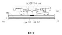
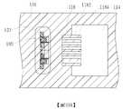
具體而言,按鍵200可為具有透光鍵帽之任何合宜的按鍵單元。圖2為本發明一實施例之發光鍵盤之按鍵之剖面示意圖。如圖2所示,於一實施例,按鍵200藉由剪刀式支撐架230可活動地連接鍵帽220及底板210,以支撐鍵帽220移動,進而壓縮彈性體250以觸發開關層240(例如薄膜開關),並藉由彈性體250的回復力復位,但不以此為限。於其他實施例,剪刀式支撐架230可以其他升降機構替代,例如蝶翼式支撐機構、滑動塊支撐機構、懸臂式支撐機構等,且彈性體250亦可以其他回復單元替代,例如磁鐵、彈簧等。再者,開關層240亦可替換為其他開關單元,例如機械開關、光學開關等。換言之,按鍵模組20的按鍵200可具有任何合宜的結構,以達到按壓後產生觸發訊號的作用。當複數按鍵200整合於鍵盤時,各按鍵200的部分元件(例如開關層240、彈性體250、底板210)可分別整合成單一部件,以促進組裝的便利性,但不以此為限。Specifically, thekey 200 can be any suitable key unit with a light-transmitting keycap. 2 is a schematic cross-sectional view of a key of an illuminated keyboard according to an embodiment of the present invention. As shown in FIG. 2 , in one embodiment, thekey 200 is movably connected to thekey cap 220 and thebottom plate 210 through the scissor-type support frame 230 to support thekey cap 220 to move, thereby compressing the elastic body 250 to trigger the switch layer 240 (eg, membrane switch), and is reset by the restoring force of the elastic body 250, but not limited thereto. In other embodiments, the scissor support frame 230 can be replaced by other lifting mechanisms, such as butterfly wing support mechanism, sliding block support mechanism, cantilever support mechanism, etc., and the elastic body 250 can also be replaced by other recovery units, such as magnets, springs, etc. . Furthermore, theswitch layer 240 can also be replaced with other switch units, such as mechanical switches, optical switches, and the like. In other words, thekey 200 of thekey module 20 can have any suitable structure, so as to achieve the function of generating a trigger signal after being pressed. When the plurality ofkeys 200 are integrated into the keyboard, some components of each key 200 (eg, theswitch layer 240 , the elastic body 250 , and the bottom plate 210 ) can be integrated into a single component to facilitate the assembly, but not limited thereto.

圖3為本發明一實施例之光學模組10之分解示意圖。如圖2及圖3所示,於一實施例,光學模組10包含光學膜片110、導光板120、反射片130及光源140。光源140提供光線,且導光板120設置於光學膜片110之一側(例如下側),用以導引光線朝複數按鍵(例如200)射出。舉例而言,光學膜片110設置於導光板120之一側(例如上方)且鄰近底板210,光學膜片110具有遮光圖案112以選擇性局部阻擋光線或讓光線通過。反射片130相對於光學膜片110設置於導光板120之另一側(例如下方),且用以將自導光板120下表面漏出的光反射回到導光板120。FIG. 3 is an exploded schematic view of theoptical module 10 according to an embodiment of the present invention. As shown in FIGS. 2 and 3 , in one embodiment, theoptical module 10 includes anoptical film 110 , alight guide plate 120 , areflection sheet 130 and alight source 140 . Thelight source 140 provides light, and thelight guide plate 120 is disposed on one side (eg, the lower side) of theoptical film 110 to guide the light to exit toward the plurality of keys (eg, 200 ). For example, theoptical film 110 is disposed on one side (eg, above) of thelight guide plate 120 and adjacent to thebottom plate 210 , and theoptical film 110 has a light-shielding pattern 112 to selectively partially block light or allow light to pass therethrough. Thereflection sheet 130 is disposed on the other side (eg, below) of thelight guide plate 120 relative to theoptical film 110 , and is used to reflect the light leaked from the lower surface of thelight guide plate 120 back to thelight guide plate 120 .

具體而言,光源140較佳為發光二極體(LED),尤其是較佳為側發光的發光二極體,但不以此為限。光源140的發光面較佳面對導光板120之入光面,以使光線透過入光面而傳遞至導光板120內。於一實施例,複數光源140較佳係整合於電路板142,以構成一體的光源單元,進而增進組裝效率。Specifically, thelight source 140 is preferably a light emitting diode (LED), especially a side-emitting light emitting diode, but not limited thereto. The light-emitting surface of thelight source 140 preferably faces the light-incident surface of thelight guide plate 120 , so that the light can pass through the light-incident surface and be transmitted to thelight guide plate 120 . In one embodiment, the plurality oflight sources 140 are preferably integrated on thecircuit board 142 to form an integrated light source unit, thereby improving assembly efficiency.

導光板120可為由任何合宜的光學材料(例如光學聚合物)製成的薄板或薄片,用以接收來自光源140的光線。導光板120的尺寸對應於按鍵模組20的尺寸,且略小於光學膜片110的尺寸。舉例而言,導光板120在X軸及/或Y軸方向的尺寸較佳小於光學膜片110的尺寸,使得光學膜片110的邊緣突出於導光板120,以利於與其他部件(例如反射片130、底板210)的黏合,但不以此為限。於此實施例,導光板120具有複數光源孔123,且光源孔123內之側表面(例如平行YZ平面)可作為導光板120的入光面,而導光板120的頂面(即沿XY軸平面延伸的上表面)作為導光板120的出光面。導光板120具有邊緣122,以定義出光面的邊界。舉例而言,導光板120的邊緣122為沿X軸方向及Y軸方向延伸並圍繞出光面的邊界線。Thelight guide plate 120 may be a thin plate or sheet made of any suitable optical material (eg, an optical polymer) for receiving light from thelight source 140 . The size of thelight guide plate 120 corresponds to the size of thekey module 20 and is slightly smaller than the size of theoptical film 110 . For example, the size of thelight guide plate 120 in the X-axis and/or the Y-axis direction is preferably smaller than the size of theoptical film 110, so that the edge of theoptical film 110 protrudes from thelight guide plate 120, so as to facilitate interaction with other components (such as a reflective sheet) 130, the bonding of the bottom plate 210), but not limited thereto. In this embodiment, thelight guide plate 120 has a plurality oflight source holes 123, and the side surfaces (for example, parallel to the YZ plane) of thelight source holes 123 can be used as the light incident surface of thelight guide plate 120, and the top surface of the light guide plate 120 (that is, along the XY axis) The upper surface extending from the plane) is used as the light emitting surface of thelight guide plate 120 . Thelight guide plate 120 has anedge 122 to define the boundary of the light exit surface. For example, theedge 122 of thelight guide plate 120 is a boundary line extending along the X-axis direction and the Y-axis direction and surrounding the light exit surface.

反射片130可為反射材料形成的反射膜片(例如金屬箔片)、或非反射膜片上塗布反射材料、或摻雜反光粒子的塑料膜片(例如摻雜反光粒子的PET膜片)所形成之反射片。反射片130之形狀、大小較佳係對應光學膜片110,且反射片130的延展性/變形性較佳大於光學膜片110。亦即,反射片130較佳比光學膜片110容易變形,使得反射片130更容易黏貼。於此實施例,反射片130具有複數穿孔133,複數穿孔133對應導光板120的光源孔123,使得光源140可自反射片130的下方穿過穿孔133插入光源孔123。藉此,光源140提供的光線經由光源孔123內側的入光面進入導光板120後,實質上係沿著導光板120的延伸方向行進,行進到光學膜片110的透光處(例如透光區114,如下詳述)而射出。Thereflective sheet 130 can be a reflective film formed of a reflective material (such as a metal foil), or a non-reflective film coated with a reflective material, or a plastic film doped with reflective particles (such as a PET film doped with reflective particles). formed reflector. The shape and size of thereflective sheet 130 preferably correspond to theoptical film 110 , and the ductility/deformability of thereflective sheet 130 is preferably greater than that of theoptical film 110 . That is, thereflective sheet 130 is preferably more easily deformed than theoptical film 110, so that thereflective sheet 130 is easier to stick. In this embodiment, thereflection sheet 130 has a plurality of throughholes 133 corresponding to the light source holes 123 of thelight guide plate 120 , so that thelight source 140 can be inserted into the light source holes 123 from below thereflection sheet 130 through the throughholes 133 . In this way, after the light provided by thelight source 140 enters thelight guide plate 120 through the light incident surface inside thelight source hole 123 , it substantially travels along the extending direction of thelight guide plate 120 to the light-transmitting part of the optical film 110 (for example, the light-transmitting part)zone 114, described in detail below).

於一實施例,光學膜片110為可透光的光學膜片(例如對苯二甲酸酯(Polyethylene Terephthalate,PET))且膜片上具有遮光材料(例如油墨)形成的遮光圖案112,但不以此為限。於其他實施例,光學膜片110可為不透光的光學膜片,且其經切割而形成遮光圖案112。光學膜片110之遮光圖案112定義一或多個透光區114、遮光區116及一或多個光量調變區118。舉例而言,透光區114為透光的光學膜片上未設置遮光材料的區域,遮光區116為透光的光學膜片上設置有遮光材料的區域,而光量調變區118自遮光區116延伸至透光區114,以至少局部調變遮光區116至透光區114之間的光能。於此實施例,遮光圖案112定義複數透光區114,且複數透光區114分別對應複數按鍵200設置。舉例而言,透光區114的數目、位置及形狀較佳對應按鍵200的數目、位置及鍵帽220的形狀,但不以此為限。於一實施例,光學膜片110之形狀、大小較佳係對應按鍵模組20的底板210,使得光學膜片110的端部上表面黏合於底板210的下表面,光學膜片110的端部下表面黏合於反射片130的上表面,以將導光板120包圍在光學膜片110及反射片130之間,防止側向漏光。再者,於一實施例,外側按鍵201的鍵帽220及底板210可與光學膜片110及反射片130的邊緣切齊,例如鍵帽220、底板210與光學膜片110及反射片130的邊緣沿堆疊方向(例如Z軸方向)彼此對準,以利於發光鍵盤1的窄邊框設計。舉例而言,對應內側按鍵202之透光區114的尺寸及形狀較佳與對應的鍵帽220一致,即透光區114與對應鍵帽220在底板210方向上的垂直投影較佳實質完全重合,而對應外側按鍵201之透光區114的尺寸及形狀因受限於黏合需求及防止側向漏光的考量,透光區114的尺寸可小於對應的鍵帽220尺寸。亦即,在各按鍵200中,鍵帽220於光學膜片110之垂直投影至少涵蓋對應的透光區114。In one embodiment, theoptical film 110 is a light-transmitting optical film (eg, Polyethylene Terephthalate (PET)), and the film has a light-shielding pattern 112 formed by a light-shielding material (eg, ink), but Not limited to this. In other embodiments, theoptical film 110 may be an opaque optical film, which is cut to form the light-shielding pattern 112 . The light-shielding pattern 112 of theoptical film 110 defines one or more light-transmittingregions 114 , a light-shieldingregion 116 and one or more light-modulatingregions 118 . For example, the light-transmittingarea 114 is an area on the light-transmitting optical film without a light-shielding material, the light-shieldingarea 116 is an area where a light-shielding material is disposed on the light-transmitting optical film, and the lightquantity modulation area 118 is formed from the light-shielding area The 116 extends to the light-transmittingarea 114 to at least partially modulate the light energy between the light-shieldingarea 116 and the light-transmittingarea 114 . In this embodiment, the light-shielding pattern 112 defines a plurality of light-transmittingregions 114 , and the plurality of light-transmittingregions 114 are respectively disposed corresponding to the plurality ofkeys 200 . For example, the number, location and shape of the light-transmittingregions 114 preferably correspond to the number, location and shape of thekey caps 220 of thekeys 200 , but not limited thereto. In one embodiment, the shape and size of theoptical film 110 preferably correspond to thebottom plate 210 of thekey module 20 , so that the upper surface of the end of theoptical film 110 is adhered to the lower surface of thebottom plate 210 , and the lower surface of the end of theoptical film 110 The surface is adhered to the upper surface of thereflection sheet 130 to surround thelight guide plate 120 between theoptical film 110 and thereflection sheet 130 to prevent lateral light leakage. Furthermore, in one embodiment, thekey caps 220 and thebottom plate 210 of theouter keys 201 can be flush with the edges of theoptical film 110 and thereflection sheet 130 , for example, thekey caps 220 , thebottom plate 210 and theoptical film 110 and thereflection sheet 130 The edges are aligned with each other along the stacking direction (eg, the Z-axis direction) to facilitate the narrow bezel design of the light-emittingkeyboard 1 . For example, the size and shape of the light-transmittingarea 114 corresponding to theinner key 202 is preferably consistent with thecorresponding keycap 220 , that is, the vertical projection of the light-transmittingarea 114 and thecorresponding keycap 220 in the direction of thebottom plate 210 is preferably substantially identical. However, the size and shape of the light-transmittingarea 114 corresponding to theouter key 201 are limited by the requirements of bonding and the consideration of preventing lateral light leakage. That is, in each key 200 , the vertical projection of thekey cap 220 on theoptical film 110 at least covers the corresponding light-transmittingarea 114 .

光量調變區118可選擇性設置於需要光量調變的一或多個按鍵的對應位置。舉例而言,如圖1及3所示,當最上列的外側按鍵201需要光量調變時,光量調變區118可沿例如X軸方向分別對應透光區114設置。光量調變區118自遮光區116延伸至透光區114。透光區114容許光線通過,遮光區116阻擋光線,且光量調變區118局部容許光線通過且局部阻擋光線,使得光量調變區118的單位面積平均光透射率小於透光區114且大於遮光區116。於後,參考圖4A至圖10B,以單個按鍵例示說明光學膜片之遮光圖案的各種配置實施例。The lightintensity modulation area 118 can be selectively disposed at the corresponding position of one or more keys that require light intensity modulation. For example, as shown in FIGS. 1 and 3 , when theouter keys 201 in the uppermost row require light quantity modulation, the lightquantity modulation areas 118 may be respectively disposed along the X-axis direction corresponding to thelight transmission areas 114 . The lightquantity modulating area 118 extends from thelight shielding area 116 to thelight transmitting area 114 . The light-transmittingarea 114 allows light to pass through, the light-shieldingarea 116 blocks light, and the light-quantity modulating area 118 partially allows light to pass through and partially blocks light, so that the average light transmittance per unit area of the light-quantity modulating area 118 is smaller than that of the light-transmittingarea 114 and greater than theshading area District 116. Next, referring to FIGS. 4A to 10B , various configuration embodiments of the light-shielding pattern of the optical film are illustrated with a single button.

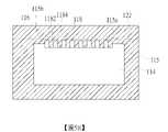
如圖4A所示,於第一實施例中,遮光區116部分環繞鄰接透光區114形成邊界線115,且邊界線115的兩端部115a、115b實質連接於光量調變區118的相對兩側的中段。舉例而言,遮光區116可視為環繞鄰接透光區114以形成實質矩形的邊界線115,而光量調變區118跨置於遮光區116及透光區114之間的部分邊界線115上,使得光量調變區118位於遮光區116及透光區114之間,且光量調變區118的兩側邊中段分別連接界線115的兩端部115a、115b。於一實施例,光量調變區118包含複數子遮光區1182及複數子透光區1184,且複數子遮光區1182及複數子透光區1184交錯設置,例如沿導光板120的邊緣122交錯設置或沿邊界線115的延伸方向交錯設置。具體而言,複數子遮光區1182為光量調變區118中設置有遮光材料的區域,而複數子透光區1184為光量調變區118中未設置遮光材料的區域。換言之,在光學膜片110中,遮光材料設置於遮光區116(例如相鄰按鍵之間的空隙或鍵盤邊緣)及複數子遮光區1182,以構成遮光圖案112。於一實施例,複數子遮光區1182各具有相對的第一端及第二端,第一端連接遮光區116,且第二端延伸至透光區114。舉例而言,複數子遮光區1182可具有相同的形狀、尺寸,且各子遮光區1182自遮光區116延伸至透光區114,但不以此為限。依據實際的光量調變需求,複數子遮光區1182可具有不同的形狀、尺寸、數目。As shown in FIG. 4A , in the first embodiment, the light-shieldingregion 116 partially surrounds the adjacent light-transmittingregion 114 to form aboundary line 115 , and the two ends 115 a and 115 b of theboundary line 115 are substantially connected to two opposite sides of the light-modulatingregion 118 . the middle of the side. For example, the light-shieldingregion 116 can be regarded as surrounding the adjacent light-transmittingregion 114 to form a substantiallyrectangular boundary line 115 , and the light-quantity modulating region 118 straddles part of theboundary line 115 between the light-shieldingregion 116 and the light-transmittingregion 114 , The lightquantity modulation area 118 is located between the light-shieldingarea 116 and the light-transmittingarea 114 , and the middle sections of the two sides of the lightquantity modulation area 118 are respectively connected to the two ends 115 a and 115 b of theboundary line 115 . In one embodiment, the lightquantity modulation region 118 includes a plurality of sub-light-shieldingregions 1182 and a plurality of sub-light-transmittingregions 1184 , and the plurality of sub-light-shieldingregions 1182 and the plurality of sub-light-transmittingregions 1184 are arranged alternately, for example, along theedge 122 of thelight guide plate 120 . Or staggered along the extending direction of theboundary line 115 . Specifically, the plurality of sub-light-shieldingregions 1182 are regions in the light-modulation region 118 where light-shielding materials are provided, and the plurality of sub-light-transmittingregions 1184 are regions in the light-modulation region 118 where no light-shielding materials are provided. In other words, in theoptical film 110 , the light-shielding material is disposed in the light-shielding region 116 (eg, the space between adjacent keys or the edge of the keyboard) and the plurality of sub-light-shieldingregions 1182 to form the light-shielding pattern 112 . In one embodiment, the plurality of sub light-shieldingregions 1182 each have a first end and a second end opposite to each other, the first end is connected to the light-shieldingregion 116 , and the second end extends to the light-transmittingregion 114 . For example, the plurality of sub-light-shieldingregions 1182 may have the same shape and size, and each sub-light-shieldingregion 1182 extends from the light-shieldingregion 116 to the light-transmittingregion 114, but not limited thereto. The plurality ofsub-shading regions 1182 may have different shapes, sizes, and numbers according to actual light intensity modulation requirements.

於此實施例,子遮光區1182具有三角形狀,使得子遮光區1182的第一端(即鄰近遮光區116)的寬度大於第二端(即鄰近透光區114)的寬度,且子遮光區1182的寬度自遮光區116朝透光區114逐漸縮減。亦即,三角形的子遮光區1182的寬底邊連接遮光區116,且其跨越邊界線115兩端部115a、115b的虛擬連線,使頂點朝向透光區114延伸。三角形的子遮光區1182沿導光板120的邊緣122相鄰設置,使得兩相鄰的子遮光區1182之間夾設有子透光區1184。對應地,子透光區1184具有類似的三角形狀,且子透光區1184的寬底邊鄰近透光區114,窄頂點鄰近遮光區116,使得光量調變區118的單位面積平均光透射率自遮光區116朝透光區114增加。舉例而言,「單位面積平均光透射率自遮光區116朝透光區114增加」係指子透光區1184的寬度自遮光區116朝透光區114增加,或光量調變區118中光可透射的面積比率沿著遮光區116朝透光區114延伸的方向增加。當光學膜片110、導光板120及反射片130相互疊置時,導光板120的邊緣122於光學膜片110的垂直投影係落在光量調變區118。藉此,光學膜片110可藉由光量調變區118的子遮光區1182遮蔽自導光板120的邊緣122射出的光線,並藉由光量調變區118的子透光區1184容許自導光板120的邊緣122射出的光線通過,以調變導光板120的邊緣122出光效果,有利於提升按鍵的發光均勻性,以適用於窄邊框的鍵盤設計。In this embodiment, the sub light-shieldingregion 1182 has a triangular shape, so that the width of the first end of the sub-light-shielding region 1182 (ie, adjacent to the light-shielding region 116 ) is greater than the width of the second end (ie, adjacent to the light-transmitting region 114 ), and the sub-light-shieldingregion 1182 has a triangular shape. The width of 1182 gradually decreases from the light-shieldingregion 116 to the light-transmittingregion 114 . That is, the wide base of the triangularsub-shading area 1182 is connected to the shadedarea 116 , and crosses the virtual connection between the two ends 115 a and 115 b of theboundary line 115 , so that the apex extends toward thetransparent area 114 . The triangular sub-light-shieldingregions 1182 are disposed adjacent to each other along theedge 122 of thelight guide plate 120 , so that a sub-light-transmittingregion 1184 is sandwiched between two adjacent sub-light-shieldingregions 1182 . Correspondingly, thesub-transmissive region 1184 has a similar triangular shape, and the wide base of thesub-transparent region 1184 is adjacent to the light-transmittingregion 114 , and the narrow vertex is adjacent to the light-shieldingregion 116 , so that the average light transmittance per unit area of the light-modulatingregion 118 is It increases from the light-shieldingregion 116 toward the light-transmittingregion 114 . For example, “the average light transmittance per unit area increases from the light-shieldingregion 116 to the light-transmittingregion 114 ” means that the width of the sub-light-transmittingregion 1184 increases from the light-shieldingregion 116 to the light-transmittingregion 114 , or that the light in the lightquantity modulation region 118 increases The transmittable area ratio increases along the direction in which the light-shieldingregion 116 extends toward the light-transmittingregion 114 . When theoptical film 110 , thelight guide plate 120 and thereflection sheet 130 are stacked on each other, the vertical projection of theedge 122 of thelight guide plate 120 on theoptical film 110 falls on the lightquantity modulation area 118 . In this way, theoptical film 110 can shield the light emitted from theedge 122 of thelight guide plate 120 by the sublight shielding region 1182 of the lightamount modulation region 118 , and allow the light emitted from the light guide plate by the sublight transmission region 1184 of the lightamount modulation region 118 The light emitted from theedge 122 of thelight guide plate 120 passes through to adjust the light output effect of theedge 122 of thelight guide plate 120 , which is beneficial to improve the uniformity of light emission of the keys, and is suitable for the design of a keyboard with a narrow frame.

如圖4B所示,於一變化例中,顯示光學膜片110之遮光圖案112與導光板120之另一相對位置示意圖。於此實施例,光學膜片110之遮光圖案112定義與圖4A類似的透光區114、遮光區116及光量調變區118,其差異在於當光學膜片110、導光板120及反射片130相互疊置時,導光板120的邊緣122於光學膜片110的垂直投影係落在遮光區116且鄰近光量調變區118。藉此,光學膜片110的遮光區116實質遮蔽自導光板120的邊緣122射出的光線,但仍可藉由光量調變區118的子透光區1184讓部分光線通過,以提升按鍵的發光均勻性。換言之,導光板120的邊緣122與光量調變區118的距離(或相對位置),可依據實際光學效果調整,當需要利用較多的自導光板120的邊緣122射出的光線時,可採用類似圖4A的設計,反之,則可使用類似圖4B的設計。As shown in FIG. 4B , in a modified example, another schematic diagram of relative positions of thelight shielding pattern 112 of theoptical film 110 and thelight guide plate 120 is shown. In this embodiment, the light-shielding pattern 112 of theoptical film 110 defines a light-transmittingarea 114 , a light-shieldingarea 116 and a lightquantity modulating area 118 similar to those in FIG. When stacked on each other, the vertical projection of theedge 122 of thelight guide plate 120 on theoptical film 110 falls on thelight shielding area 116 and is adjacent to the lightquantity modulation area 118 . In this way, the light-shieldingarea 116 of theoptical film 110 substantially shields the light emitted from theedge 122 of thelight guide plate 120, but part of the light can still pass through thesub-transmissive area 1184 of the lightquantity modulation area 118, so as to enhance the light emission of the keys uniformity. In other words, the distance (or relative position) between theedge 122 of thelight guide plate 120 and the lightquantity modulation area 118 can be adjusted according to the actual optical effect. The design of FIG. 4A, otherwise, a design similar to that of FIG. 4B can be used.

圖5A及圖5B所示,為本發明第二實施例之光學膜片110之遮光圖案112之示意圖。光量調變區118包含複數子遮光區1182及複數子透光區1184,且複數子遮光區1182及複數子透光區1184沿導光板120的邊緣122(或沿邊界線115的延伸方向)交錯設置。於後,僅著重於與前述實施例的差異,其餘類似或相同部分不再贅述。於此實施例,子遮光區1182為矩形,使得子遮光區1182的第一端的寬度等於第二端的寬度。複數子遮光區1182沿著導光板120的邊緣122間隔設置,使得兩相鄰的子遮光區1182之間夾設有子透光區1184。對應地,子透光區1184具有類似的矩形,使得光量調變區118的單位面積平均光透射率自遮光區116朝透光區114實質為固定。換言之,子透光區1184的寬度自遮光區116朝透光區114實質為固定,或者光量調變區118中光可透射的面積比率沿著遮光區116朝透光區114延伸的方向實質為固定。再者,圖5A顯示導光板120的邊緣於光學膜片110的垂直投影落在光量調變區118,且圖5B顯示導光板120的邊緣於光學膜片110的垂直投影落在遮光區116且鄰近光量調變區118。導光板120的邊緣122與光量調變區118的距離(或相對位置),可依據實際光學效果調整,以選擇使用類似圖5A或圖5B的配置。5A and 5B are schematic diagrams of the light-shielding pattern 112 of theoptical film 110 according to the second embodiment of the present invention. The lightquantity modulation region 118 includes a plurality of sub-light-shieldingregions 1182 and a plurality of sub-light-transmittingregions 1184 , and the plurality of sub-light-shieldingregions 1182 and the plurality of sub-light-transmittingregions 1184 are staggered along theedge 122 of the light guide plate 120 (or along the extending direction of the boundary line 115 ) . Hereinafter, only the differences from the foregoing embodiments will be emphasized, and the remaining similar or identical parts will not be repeated. In this embodiment, thesub-shading area 1182 is rectangular, so that the width of the first end of thesub-shading area 1182 is equal to the width of the second end. The plurality of sub-light-shieldingregions 1182 are arranged at intervals along theedge 122 of thelight guide plate 120 , so that a sub-light-transmittingregion 1184 is sandwiched between two adjacent sub-light-shieldingregions 1182 . Correspondingly, thesub-transmissive regions 1184 have similar rectangular shapes, so that the average light transmittance per unit area of the light-modulation region 118 is substantially constant from the light-shieldingregion 116 to the light-transmittingregion 114 . In other words, the width of thesub-transmissive region 1184 is substantially constant from the light-shieldingregion 116 to the light-transmittingregion 114 , or the area ratio of the light-transmittable area in the light-modulation region 118 along the extending direction of the light-shieldingregion 116 toward the light-transmittingregion 114 is substantially fixed. Furthermore, FIG. 5A shows that the vertical projection of the edge of thelight guide plate 120 on theoptical film 110 falls on the lightquantity modulation area 118 , and FIG. 5B shows that the vertical projection of the edge of thelight guide plate 120 on theoptical film 110 falls on thelight shielding area 116 and It is adjacent to the lightquantity modulation area 118 . The distance (or relative position) between theedge 122 of thelight guide plate 120 and the lightquantity modulating area 118 can be adjusted according to the actual optical effect, so that a configuration similar to FIG. 5A or FIG. 5B can be selected.

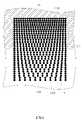
上述實施例中,光量調變區雖繪示為三角形或矩形的子遮光區及子透光區,但不以此為限。於另一實施例(未繪示),子遮光區及子透光區可具有任何合宜的形狀,例如梯形,但不以此為限。於其他實施例,依據實際應用,光量調變區可藉由印刷技術形成漸層式的設計,使得光量調變區118的光透射率沿著遮光區116朝透光區114延伸的方向增加。如圖6所示,圖6顯示光量調變區118中遮光材料以點陣式方式形成複數子遮光區1182及未被遮光材料覆蓋的區域為子透光區1184。於此實施例中,子遮光區1182以佈點方式設置,且子遮光區1182的分布密度由遮光區116朝透光區114減少。亦即,子遮光區1182的分布密度越接近遮光區116變得越大,且越接近透光區114變得越小,不以此為限。於圖6的實施例中,各子遮光區1182互不重疊,但不以此為限;於其他實施例中,依據實際應用及光學需求,複數子遮光區1182可局部重疊。In the above-mentioned embodiment, although the light quantity modulation area is shown as a triangular or rectangular sub-shielding area and a sub-transmitting area, it is not limited to this. In another embodiment (not shown), the sub-light-shielding regions and the sub-light-transmitting regions may have any suitable shape, such as a trapezoid, but not limited thereto. In other embodiments, according to practical applications, the light intensity modulation region can be formed with a gradient design by printing technology, so that the light transmittance of the lightintensity modulation region 118 increases along the direction extending from thelight shielding region 116 to thelight transmission region 114 . As shown in FIG. 6 , FIG. 6 shows that the light-shielding material in the lightquantity modulation region 118 forms a plurality of sub-light-shieldingregions 1182 in a dot matrix manner, and the region not covered by the light-shielding material is the sub-light-transmittingregion 1184 . In this embodiment, the sub-light-shieldingregions 1182 are arranged in a dotted manner, and the distribution density of the sub-light-shieldingregions 1182 decreases from the light-shieldingregion 116 to the light-transmittingregion 114 . That is, the distribution density of the sub light-shieldingregion 1182 becomes larger as it approaches the light-shieldingregion 116 , and becomes smaller as it approaches the light-transmittingregion 114 , which is not limited thereto. In the embodiment of FIG. 6 , thesub-shading regions 1182 do not overlap with each other, but not limited thereto; in other embodiments, a plurality ofsub-shading regions 1182 may partially overlap according to practical applications and optical requirements.

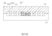
如圖7A及圖7B所示,其分別顯示圖4A及圖5A之光量調變區與鍵帽之透光字符222之相對位置。於此實施例,鍵帽220之透光字符222以「Esc」為例。光量調變區118之複數子遮光區1182及複數子透光區1184較佳沿透光字符222的設置方向交錯設置。亦即,複數子遮光區1182及複數子透光區1184較佳沿透光字符222的長軸方向設置。於一實施例,光量調變區118自遮光區116延伸至透光區114的長度及沿邊界線115的寬度較佳至少等於透光字符222的高度及長度(例如涵蓋整個字符高度及長度),且邊界線115較佳為連接光量調變區118於約1/2的字符高度處,但不以此為限。As shown in FIG. 7A and FIG. 7B , the relative positions of the light quantity modulation area of FIG. 4A and FIG. 5A and the light-transmittingcharacters 222 of the keycap are respectively shown. In this embodiment, the light-transmittingcharacter 222 of thekeycap 220 is "Esc" as an example. The plurality of sub-light-shieldingregions 1182 and the plurality of sub-light-transmittingregions 1184 of the lightquantity modulation region 118 are preferably arranged alternately along the arrangement direction of the light-transmittingcharacters 222 . That is, the plurality of sub-light-shieldingregions 1182 and the plurality of sub-light-transmittingregions 1184 are preferably disposed along the long axis direction of the light-transmittingcharacters 222 . In one embodiment, the length of the light-modulatingregion 118 extending from the light-shieldingregion 116 to the light-transmittingregion 114 and the width along theboundary line 115 are preferably at least equal to the height and length of the light-transmitting characters 222 (for example, covering the entire character height and length), In addition, theboundary line 115 is preferably connected to the lightquantity modulation area 118 at about 1/2 of the character height, but not limited thereto.

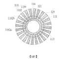
此外,如圖1及所示,為了散熱或是定位設計,光學模組10通常開設有貫孔101,以供氣流或供定位機構(例如定位柱、螺絲等)通過。如圖3所示,光學膜片110具有上通孔111,導光板120具有孔洞121,且反射片130具有下通孔131。當光學膜片110、導光板120及反射片130依序疊置時,上通孔111、孔洞121及下通孔131相互對準而形成貫孔101。當貫孔101的位置至少部分在按鍵200的垂直投影範圍內時,光量調變區118可設置於對應該按鍵200的位置。如圖8所示,導光板120的孔洞121定義孔緣125。光學膜片110的上通孔111的孔緣113位於導光板120的孔緣125的內側,即上通孔111的直徑小於孔洞121的直徑,使得光學膜片110突出孔洞121周圍形成環形的遮光區116。光量調變區118的複數子遮光區1182及複數子透光區1184沿導光板120的孔緣125交錯設置,且自遮光區116延伸至透光區114。具體而言,依據貫孔101對應鍵帽220的實際位置,光量調變區118可完全環繞或局部環繞遮光區114,以使光量調變區118為完整的環形區或局部環形的扇形區。於此實施例,光量調變區118繪示為實質完全環繞遮光區114(即貫孔101實質完全在對應鍵帽220的透光區114範圍內),使得透光區114可為環繞光量調變區118的外圍部分,但不以此為限。於其他實施例,光量調變區118可為局部環繞遮光區114的扇形區,即貫孔101僅部分在對應鍵帽220的透光區114範圍內,使得透光區114圍繞扇形區的外扇緣,而遮光區116連接扇形區的側邊並延伸至扇形區的內扇緣。In addition, as shown in FIG. 1 , for heat dissipation or positioning design, theoptical module 10 is usually provided with throughholes 101 for air flow or for positioning mechanisms (eg, positioning posts, screws, etc.) to pass through. As shown in FIG. 3 , theoptical film 110 has an upper throughhole 111 , thelight guide plate 120 has ahole 121 , and thereflection sheet 130 has a lower throughhole 131 . When theoptical film 110 , thelight guide plate 120 and thereflection sheet 130 are stacked in sequence, the upper throughhole 111 , thehole 121 and the lower throughhole 131 are aligned with each other to form the throughhole 101 . When the position of the throughhole 101 is at least partially within the vertical projection range of the key 200 , the lightquantity modulation area 118 may be disposed at a position corresponding to the key 200 . As shown in FIG. 8 , thehole 121 of thelight guide plate 120 defines ahole edge 125 . Thehole edge 113 of the upper throughhole 111 of theoptical film 110 is located inside thehole edge 125 of thelight guide plate 120 , that is, the diameter of the upper throughhole 111 is smaller than the diameter of thehole 121 , so that theoptical film 110 protrudes around thehole 121 to form a ring-shapedlight shield District 116. The plurality of sub-light-shieldingregions 1182 and the plurality of sub-light-transmittingregions 1184 of the lightquantity modulating region 118 are arranged alternately along thehole edge 125 of thelight guide plate 120 and extend from the light-shieldingregion 116 to the light-transmittingregion 114 . Specifically, according to the actual position of the throughhole 101 corresponding to thekeycap 220 , thelight modulation area 118 can completely or partially surround thelight shielding area 114 , so that thelight modulation area 118 is a complete annular area or a partially annular sector. In this embodiment, the lightintensity modulation area 118 is shown as substantially completely surrounding the light shielding area 114 (that is, the throughhole 101 is substantially completely within the range of thelight transmission area 114 corresponding to the keycap 220 ), so that thelight transmission area 114 can surround the light intensity adjustment. The peripheral portion of thevariable region 118, but not limited thereto. In other embodiments, the lightquantity modulating area 118 may be a fan-shaped area that partially surrounds the light-shieldingarea 114 , that is, the throughhole 101 is only partially within the range of the light-transmittingarea 114 corresponding to thekeycap 220 , so that the light-transmittingarea 114 surrounds the outside of the fan-shaped area. Theshading area 116 is connected to the side edges of the fan-shaped area and extends to the inner fan edge of the fan-shaped area.

於此實施例,各子遮光部1182具有類三角形,且子遮光部1182的第一端1182a連接遮光區116,且第二端1182b延伸至透光區114。子遮光部1182的第一端1182a的寬度大於第二端1182b的寬度,使得子遮光區1182的寬度自遮光區116朝透光區114逐漸縮減。於此實施例,各子遮光部1182的第二端1182b的中心線(例如角平分線)較佳通過孔洞121及上通孔111的中心。複數子遮光區1182沿導光板120的孔緣125相鄰設置,使得兩相鄰的子遮光區1182之間夾設有子透光區1184。對應地,子透光區1184具有類似的三角形狀,且由於光量調變區118環繞遮光區116沿徑向向外朝透光區114延伸,子透光區1184的寬底邊鄰近透光區114且大於子遮光區1182的第一端1182的弧長,而窄頂點鄰近遮光區116,使得光量調變區118的單位面積平均光透射率自遮光區116朝透光區114增加。於此實施例,光學膜片110、導光板120及反射片130相互疊置時,導光板120的孔緣125於光學膜片110的垂直投影較佳落在光量調變區118,以達到藉由光量調變區118提升貫孔101對應的按鍵200的發光均勻性。In this embodiment, eachsub-shading portion 1182 has a triangular-like shape, and thefirst end 1182 a of thesub-shading portion 1182 is connected to the light-shieldingregion 116 , and thesecond end 1182 b extends to the light-transmittingregion 114 . The width of thefirst end 1182 a of thesub-shading portion 1182 is greater than the width of thesecond end 1182 b , so that the width of thesub-shading region 1182 gradually decreases from the light-shieldingregion 116 to the light-transmittingregion 114 . In this embodiment, the center line (eg, the angle bisector) of thesecond end 1182b of eachsub-shading portion 1182 preferably passes through the center of thehole 121 and the upper throughhole 111 . The plurality of sub-light-shieldingregions 1182 are disposed adjacent to each other along thehole edge 125 of thelight guide plate 120 , so that a sub-light-transmittingregion 1184 is sandwiched between two adjacent sub-light-shieldingregions 1182 . Correspondingly, thesub-transmissive region 1184 has a similar triangular shape, and since the lightquantity modulation region 118 surrounds the light-shieldingregion 116 and extends radially outward toward the light-transmittingregion 114 , the wide base of thesub-transmissive region 1184 is adjacent to the light-transmittingregion 114 and greater than the arc length of thefirst end 1182 of the sub light-shieldingregion 1182 , and the narrow apex is adjacent to the light-shieldingregion 116 , so that the average light transmittance per unit area of the lightquantity modulation region 118 increases from the light-shieldingregion 116 to the light-transmittingregion 114 . In this embodiment, when theoptical film 110 , thelight guide plate 120 and thereflective sheet 130 are stacked on each other, the vertical projection of thehole edge 125 of thelight guide plate 120 on theoptical film 110 preferably falls on the lightquantity modulation area 118 , so as to achieve the purpose of using The light emission uniformity of thekeys 200 corresponding to the throughholes 101 is improved by the lightquantity modulation area 118 .

圖9為圖8的變化例。於此實施例,子遮光區1182為扇形,其中扇形的兩邊緣的延伸方向較佳通過孔洞121及上通孔111的中心。於此實施例,由於光量調變區118環繞遮光區116沿徑向向外朝透光區114延伸,子遮光區1182的第一端1182a的寬度小於第二端1184b的寬度,且子遮光區1182的寬度自遮光區116朝透光區114增加。亦即,複數子遮光區1182沿著導光板120的孔緣125間隔設置,使得兩相鄰的子遮光區1182之間夾設有子透光區1184。對應地,子透光區1184具有類似的扇形,且子透光區1184的寬度自遮光區116朝透光區114逐漸增加,其中光量調變區118中光可透射的面積比率沿著遮光區116朝透光區114延伸的方向雖未增加,但是光量調變區118中光可透射的面積隨著與遮光區116的距離逐漸增加。於此實施例,光學膜片110、導光板120及反射片130相互疊置時,導光板120的孔緣125於光學膜片110的垂直投影較佳落在光量調變區118,以達到藉由光量調變區118提升貫孔101對應的按鍵200的發光均勻性。FIG. 9 is a modification of FIG. 8 . In this embodiment, thesub-shading region 1182 is fan-shaped, wherein the extending directions of the two edges of the fan-shaped preferably pass through the center of thehole 121 and the upper throughhole 111 . In this embodiment, since the lightquantity modulation region 118 surrounds thelight shielding region 116 and extends radially outward toward thelight transmitting region 114 , the width of thefirst end 1182a of the sublight shielding region 1182 is smaller than the width of the second end 1184b, and the sub light shielding region The width of 1182 increases from the light-shieldingregion 116 toward the light-transmittingregion 114 . That is, the plurality of sub-light-shieldingregions 1182 are arranged at intervals along thehole edge 125 of thelight guide plate 120 , so that the sub-light-transmittingregions 1184 are sandwiched between two adjacent sub-light-shieldingregions 1182 . Correspondingly, thesub-transmissive regions 1184 have a similar fan shape, and the widths of thesub-transmissive regions 1184 gradually increase from the light-shieldingregion 116 to the light-transmittingregion 114 , wherein the area ratio of the light-transmitting area in the lightquantity modulation region 118 is along the light-shielding region. Although the extending direction of 116 toward the light-transmittingregion 114 does not increase, the light-transmissible area in the light-quantity modulating region 118 gradually increases with the distance from the light-shieldingregion 116 . In this embodiment, when theoptical film 110 , thelight guide plate 120 and thereflective sheet 130 are stacked on each other, the vertical projection of thehole edge 125 of thelight guide plate 120 on theoptical film 110 preferably falls on the lightquantity modulation area 118 , so as to achieve the purpose of using The light emission uniformity of thekeys 200 corresponding to the throughholes 101 is improved by the lightquantity modulation area 118 .

再者,圖8及圖9之光量調變區118的設計亦可應用於按鍵的彎角部分。於此情況下,光學膜片110可不具有上通孔111,且光學膜片110地遮光區116延伸至對應上通孔111的位置,以提升按鍵位的彎角部分的發光均勻性或光暈表現。此外,於圖8及圖9之實施例中,光量調變區118的子遮光區1182(或子透光區1184)的數目、形狀、尺寸可依據實際需求(例如光線強度、漏光程度)來改變。Furthermore, the design of the lightquantity modulation area 118 shown in FIGS. 8 and 9 can also be applied to the corners of the keys. In this case, theoptical film 110 may not have the upper throughhole 111, and the light-shieldingarea 116 of theoptical film 110 extends to the position corresponding to the upper throughhole 111, so as to improve the lighting uniformity or halo of the corner portion of the key position Performance. In addition, in the embodiments of FIG. 8 and FIG. 9 , the number, shape, and size of the sub-light-shielding regions 1182 (or the sub-light-transmitting regions 1184 ) of the lightquantity modulation region 118 can be determined according to actual requirements (eg, light intensity, light leakage degree). Change.

圖10A為本發明第五實施例之光學膜片之遮光圖案與光源之相對位置示意圖,且圖10B為圖10A的變化例。如圖10A及圖10B所示,光源140設置於導光板120的光源孔123,且光學膜片110設置於導光板120的上方並覆蓋光源孔123(及光源140)。當光源140鄰近於按鍵200時,光學膜片110於對應該按鍵200的位置可設置光量調變區118,以調變按鍵的發光均勻性。舉例而言,遮光區116延伸覆蓋光源孔123(及光源140),且光量調變區118可設置在對應光源140的出光面的位置,並自遮光區116朝透光區114延伸。光量調變區118的複數子遮光區1182及複數子透光區1184可沿光源140的出光面的延伸方向交錯設置。於圖10A的實施例中,光量調變區118具有如圖4A的結構,其中子遮光區1182的寬度自遮光區116朝透光區114逐漸縮減,且光量調變區118的單位面積平均光透射率自遮光區116朝透光區114增加。於圖10B的實施例中,光量調變區118具有如圖4B的結構,其中子遮光區1182的寬度自遮光區116朝透光區114實質為固定,且光量調變區118的單位面積平均光透射率自遮光區116朝透光區114實質為固定。依據實際應用,子遮光區1182及子透光區1184的數目、形狀及尺寸可依據光源140提供的光量、透光區114與光源140的距離、鍵帽220的透光字符222位置等來變化,以達到所預期的光學效果。FIG. 10A is a schematic diagram of the relative positions of the light-shielding pattern and the light source of the optical film according to the fifth embodiment of the present invention, and FIG. 10B is a modification of FIG. 10A . As shown in FIGS. 10A and 10B , thelight source 140 is disposed in thelight source hole 123 of thelight guide plate 120 , and theoptical film 110 is disposed above thelight guide plate 120 and covers the light source hole 123 (and the light source 140 ). When thelight source 140 is adjacent to the key 200 , theoptical film 110 can be provided with a lightquantity modulating area 118 at a position corresponding to the key 200 to adjust the uniformity of light emission of the key. For example, theshading area 116 extends to cover the light source hole 123 (and the light source 140 ), and the lightquantity modulation area 118 may be disposed at a position corresponding to the light emitting surface of thelight source 140 and extend from theshading area 116 to thelight transmitting area 114 . The plurality of sub-light-shieldingregions 1182 and the plurality of sub-light-transmittingregions 1184 of the lightquantity modulation region 118 may be arranged in a staggered manner along the extending direction of the light-emitting surface of thelight source 140 . In the embodiment of FIG. 10A , the lightintensity modulation area 118 has the structure shown in FIG. 4A , in which the width of thesub-shading area 1182 gradually decreases from thelight shielding area 116 to thelight transmission area 114 , and the average light intensity per unit area of the lightintensity modulation area 118 is The transmittance increases from the light-shieldingregion 116 toward the light-transmittingregion 114 . In the embodiment of FIG. 10B , the lightintensity modulating area 118 has the structure shown in FIG. 4B , wherein the width of thesub-shading area 1182 is substantially constant from theshading area 116 to thelight transmitting area 114 , and the unit area of the lightintensity modulating area 118 is average. The light transmittance is substantially constant from the light-shieldingregion 116 to the light-transmittingregion 114 . According to practical applications, the number, shape and size of the sub-light-shieldingregions 1182 and the sub-light-transmittingregions 1184 can be changed according to the amount of light provided by thelight source 140 , the distance between the light-transmittingregion 114 and thelight source 140 , the position of the light-transmittingcharacters 222 of thekeycap 220 , etc. , to achieve the desired optical effect.

在此須注意,可依據實際應用將上述實施例中的一或多種光量調變區的配置方式整合於單一發光鍵盤,以藉由光學膜片的遮光圖案設計,以調變外側按鍵、鄰近孔洞按鍵、及/或鄰近光源按鍵的亮度,進而提升按鍵發光的均勻性。It should be noted here that the configuration of one or more light-modulating regions in the above-mentioned embodiments can be integrated into a single light-emitting keyboard according to practical applications, so as to modulate the outer keys and the adjacent holes through the shading pattern design of the optical film The brightness of the keys and/or the keys adjacent to the light source, thereby improving the uniformity of the light emission of the keys.

本發明已由上述實施例加以描述,然而上述實施例僅為例示目的而非用於限制。熟此技藝者當知在不悖離本發明精神下,於此特別說明的實施例可有例示實施例的其他修改。因此,本發明範疇亦涵蓋此類修改且僅由所附申請專利範圍限制。The present invention has been described by the above-mentioned embodiments, however, the above-mentioned embodiments are for illustrative purposes only and not for limitation. Those skilled in the art will appreciate that the embodiments specifically described herein may incorporate other modifications of the illustrated embodiments without departing from the spirit of the invention. Accordingly, the scope of the present invention also encompasses such modifications and is limited only by the scope of the appended claims.

1:發光鍵盤 10:光學模組 101:貫孔 110:光學膜片 111:上通孔 112:遮光圖案 113:孔緣 114:透光區 115:邊界線 115a、115b:端部 116:遮光區 118:光量調變區 1182:子遮光區 1182a:第一端 1182b:第二端 1184:子透光區 120:導光板 121:孔洞 122:邊緣 123:光源孔 125:孔緣 130:反射片 131:下通孔 133:穿孔 140:光源 142:電路板 20:按鍵模組 200:按鍵 201:外側按鍵 202:內側按鍵 210:底板 220:鍵帽 222:透光字符 230:剪刀式支撐架 240:開關層 250:彈性體1: Illuminated keyboard 10: Optical module 101: Through hole 110: Optical film 111: Upper through hole 112: Shading Pattern 113: Hole edge 114: Translucent area 115:Boundary Line 115a, 115b: end 116: Shading area 118: Light quantity modulation area 1182:Sub shading area 1182a:First End 1182b: second end 1184: Sub-transparent area 120: light guide plate 121: Hole 122: Edge 123: light source hole 125: hole edge 130: Reflector 131: Lower through hole 133: Perforation 140: light source 142: circuit board 20:Key module 200: key 201: Outside buttons 202: Inside button 210: Bottom plate 220: keycap 222: Translucent characters 230: Scissor support frame 240: switch layer 250: Elastomer

圖1為本發明一實施例之發光鍵盤之爆炸示意圖。 圖2為本發明一實施例之發光鍵盤之按鍵之剖面示意圖。 圖3為本發明一實施例之光學模組之平面分解示意圖。 圖4A為本發明第一實施例之光學膜片之遮光圖案及其與導光板之相對位置示意圖。 圖4B為圖4A之變化例,以顯示與導光板之另一相對位置示意圖。 圖5A為本發明第二實施例之光學膜片之遮光圖案及其與導光板之相對位置示意圖。 圖5B為圖5A之變化例,以顯示與導光板之另一相對位置示意圖。 圖6為本發明之光學膜片之光量調變區之變化例之示意圖。 圖7A為本發明之光學膜片之光量調變區與鍵帽之透光字符之相對位置示意圖。 圖7B為圖7A之變化例。 圖8為本發明第三實施例之光學膜片之遮光圖案與導光板之相對位置示意圖。 圖9為本發明第四實施例之光學膜片之遮光圖案與導光板之相對位置示意圖。 圖10A為本發明第五實施例之光學膜片之遮光圖案與光源之相對位置示意圖。 圖10B為圖10A之變化例。FIG. 1 is an exploded schematic diagram of a light-emitting keyboard according to an embodiment of the present invention. 2 is a schematic cross-sectional view of a key of an illuminated keyboard according to an embodiment of the present invention. 3 is a schematic exploded plan view of an optical module according to an embodiment of the present invention. 4A is a schematic diagram of the light-shielding pattern of the optical film and its relative position with the light guide plate according to the first embodiment of the present invention. FIG. 4B is a modification example of FIG. 4A , which is a schematic diagram showing another relative position with the light guide plate. 5A is a schematic diagram of the light-shielding pattern of the optical film and its relative position with the light guide plate according to the second embodiment of the present invention. FIG. 5B is a modification example of FIG. 5A , which is a schematic diagram showing another relative position with the light guide plate. FIG. 6 is a schematic diagram of a variation example of the light quantity modulation region of the optical film of the present invention. FIG. 7A is a schematic diagram showing the relative positions of the light quantity modulation area of the optical film of the present invention and the light-transmitting characters of the keycap. FIG. 7B is a modification of FIG. 7A . 8 is a schematic diagram of the relative positions of the light shielding pattern of the optical film and the light guide plate according to the third embodiment of the present invention. 9 is a schematic diagram of the relative positions of the light-shielding pattern of the optical film and the light guide plate according to the fourth embodiment of the present invention. 10A is a schematic diagram of the relative positions of the light-shielding pattern and the light source of the optical film according to the fifth embodiment of the present invention. FIG. 10B is a modification of FIG. 10A .

114:透光區114: Translucent area

115:邊界線115: Boundary Line

115a、115b:端部115a, 115b: end

116:遮光區116: Shading area

118:光量調變區118: Light quantity modulation area

1182:子遮光區1182: Sub shading area

1184:子透光區1184: Sub-transparent area

122:邊緣122: Edge

Claims (13)

Translated fromChinese
一種適用於一發光鍵盤之光學模組,包含: 一導光板; 一反射片,設置於該導光板之一側;以及 一光學膜片,相對於該反射片設置於該導光板之另一側,該光學膜片具有一遮光圖案,該遮光圖案定義一透光區、一遮光區及一光量調變區,且該光量調變區自該遮光區延伸至該透光區,其中: 該透光區容許光線通過, 該遮光區阻擋光線, 並且,該光量調變區局部容許光線通過且局部阻擋光線,使得該光量調變區的單位面積平均光透射率小於該透光區且大於該遮光區。An optical module suitable for a light-emitting keyboard, comprising: a light guide plate; a reflective sheet disposed on one side of the light guide plate; and An optical film is disposed on the other side of the light guide plate relative to the reflective sheet, the optical film has a light-shielding pattern, the light-shielding pattern defines a light-transmitting area, a light-shielding area and a light quantity modulation area, and the The light quantity modulating area extends from the shading area to the light transmitting area, wherein: The light-transmitting area allows light to pass through, The shading area blocks light, In addition, the light quantity modulation area partially allows light to pass through and partially blocks light, so that the average light transmittance per unit area of the light quantity modulation area is smaller than the light transmission area and larger than the light shielding area.如請求項1所述之光學模組,其中該光量調變區包含複數子遮光區及複數子透光區,且該複數子遮光區及該複數子透光區交錯設置。The optical module according to claim 1, wherein the light quantity modulation area comprises a plurality of sub-light-shielding regions and a plurality of sub-light-transmitting regions, and the plurality of sub-light-shielding regions and the plurality of sub-light-transmitting regions are arranged alternately.如請求項2所述之光學模組,其中該複數子遮光區各具有相對的一第一端及一第二端,該第一端連接該遮光區,且該第二端延伸至該透光區。The optical module as claimed in claim 2, wherein each of the plurality of sub-shading areas has a first end and a second end opposite to each other, the first end is connected to the shading area, and the second end extends to the light-transmitting area Area.如請求項3所述之光學模組,其中該第一端的寬度大於或等於該第二端的寬度,且當該第一端的寬度大於該第二端的寬度時,該子遮光區的寬度自該遮光區朝該透光區逐漸縮減。The optical module of claim 3, wherein the width of the first end is greater than or equal to the width of the second end, and when the width of the first end is greater than the width of the second end, the width of the sub-shading area is automatically The light-shielding area is gradually reduced toward the light-transmitting area.如請求項3所述之光學模組,其中該光量調變區環繞該遮光區,該第一端的寬度小於該第二端的寬度,且該子遮光區的寬度自該遮光區朝該透光區逐漸增加。The optical module as claimed in claim 3, wherein the light quantity modulation region surrounds the light shielding region, the width of the first end is smaller than the width of the second end, and the width of the sub light shielding region extends from the light shielding region toward the light transmission area gradually increased.如請求項1所述之光學模組,其中該遮光區部分環繞鄰接該透光區形成一邊界線,且該邊界線的兩端部實質連接於該光量調變區的相對兩側的中段。The optical module as claimed in claim 1, wherein a portion of the light-shielding area surrounds and adjoins the light-transmitting area to form a boundary line, and both ends of the boundary line are substantially connected to middle sections of opposite sides of the light quantity modulation area.如請求項1所述之光學模組,其中該光量調變區的該單位面積平均光透射率自該遮光區朝該透光區增加或固定。The optical module of claim 1, wherein the average light transmittance per unit area of the light quantity modulation region increases or is fixed from the light shielding region to the light transmitting region.如請求項1所述之光學模組,其中該導光板具有一邊緣,當該光學膜片、該導光板及該反射片相互疊置時,該導光板的該邊緣於該光學膜片的垂直投影至少部分落在該光量調變區,或者落在該遮光區且鄰近該光量調變區。The optical module according to claim 1, wherein the light guide plate has an edge, and when the optical film, the light guide plate and the reflection sheet are stacked on each other, the edge of the light guide plate is perpendicular to the optical film At least part of the projection falls on the light quantity modulating area, or falls on the shading area and is adjacent to the light quantity modulating area.如請求項8所述之光學模組,其中該複數子遮光區及該複數子透光區沿該導光板的該邊緣交錯設置。The optical module according to claim 8, wherein the plurality of sub-light-shielding regions and the plurality of sub-light-transmitting regions are staggered along the edge of the light guide plate.如請求項5所述之光學模組,其中該導光板具有一孔洞,該孔洞定義一孔緣,當該光學膜片、該導光板及該反射片相互疊置時,該導光板的該孔緣於該光學膜片的垂直投至少部分影落在該光量調變區,且該複數子遮光區及該複數子透光區沿該導光板的該孔緣交錯設置。The optical module according to claim 5, wherein the light guide plate has a hole, the hole defines a hole edge, and when the optical film, the light guide plate and the reflection sheet are overlapped with each other, the hole of the light guide plate At least part of the vertical projection of the optical film falls on the light quantity modulation area, and the plurality of sub-light-shielding areas and the plurality of sub-light-transmitting areas are staggered along the hole edge of the light guide plate.如請求項1所述之光學模組,更包含一光源,具有一發光面,其中該導光板導引該光源發出的光線,且該光源於該光學膜片的垂直投影落在該遮光區,且該光量調變區自該遮光區延伸於該透光區及該發光面之間。The optical module according to claim 1, further comprising a light source with a light-emitting surface, wherein the light guide plate guides the light emitted by the light source, and the vertical projection of the light source on the optical film falls on the light-shielding area, And the light quantity modulation area extends from the light shielding area between the light transmission area and the light emitting surface.一種發光鍵盤,包含: 如請求項1至11任一項所述的光學模組;以及 至少一按鍵,設置於該光學模組上方,該按鍵包含一鍵帽, 其中該鍵帽於該光學膜片之垂直投影至少涵蓋該透光區。An illuminated keyboard comprising: The optical module of any one of claims 1 to 11; and At least one key is arranged above the optical module, the key includes a key cap, The vertical projection of the keycap on the optical film covers at least the light-transmitting area.如請求項12所述之發光鍵盤,其中該鍵帽具有一透光字符,當該光量調變區包含該複數子遮光區及該複數子透光區時,該複數子遮光區及該複數子透光區沿該透光字符的設置方向交錯設置。The light-emitting keyboard of claim 12, wherein the keycap has a light-transmitting character, and when the light-quantity modulation region includes the plurality of sub-light-shielding regions and the plurality of sub-light-transmitting regions, the plurality of sub-light-shielding regions and the plurality of sub-light-transmitting regions The light-transmitting areas are arranged alternately along the setting direction of the light-transmitting characters.
TW110103600A2021-01-292021-01-29Luminous keyboard and optical module thereofTWI765552B (en)

Priority Applications (3)

Application NumberPriority DateFiling DateTitle
TW110103600ATWI765552B (en)2021-01-292021-01-29Luminous keyboard and optical module thereof
US17/585,714US11520101B2 (en)2021-01-292022-01-27Luminous keyboard and optical module thereof
US17/585,699US11852861B2 (en)2021-01-292022-01-27Luminous keyboard and optical module thereof

Applications Claiming Priority (1)

Application NumberPriority DateFiling DateTitle
TW110103600ATWI765552B (en)2021-01-292021-01-29Luminous keyboard and optical module thereof

Publications (2)

Publication NumberPublication Date
TWI765552B TWI765552B (en)2022-05-21
TW202230413Atrue TW202230413A (en)2022-08-01

Family

ID=82594337

Family Applications (1)

Application NumberTitlePriority DateFiling Date
TW110103600ATWI765552B (en)2021-01-292021-01-29Luminous keyboard and optical module thereof

Country Status (1)

CountryLink
TW (1)TWI765552B (en)

Families Citing this family (1)

* Cited by examiner, † Cited by third party
Publication numberPriority datePublication dateAssigneeTitle
US12154729B2 (en)2023-02-102024-11-26Darfon Electronics Corp.Lighting keyboard and backlight module for the same

Also Published As

Publication numberPublication date
TWI765552B (en)2022-05-21

Similar Documents

PublicationPublication DateTitle
US11664177B2 (en)Backlight module
TWI416565B (en)Illuminating keyboard
US11520101B2 (en)Luminous keyboard and optical module thereof
CN219892083U (en)Light source circuit board, backlight module and luminous key
CN108305809B (en)Illuminated keyboard and its backlight module
US20240096567A1 (en)Backlight module and backlight keyswitch thereof
TWI846373B (en)Backlit module and illuminated keyswitch structure
CN104183406B (en) Illuminated keyboard device
TWI765552B (en)Luminous keyboard and optical module thereof
TWI848426B (en)Luminous keyboard and optical module thereof
CN212725101U (en)Backlight keyboard
US12204135B2 (en)Backlit module and illuminated keyswitch structure
US12027326B2 (en)Backlit module and illuminated keyswitch structure
CN114914113A (en)Luminous keyboard and optical module thereof
TW202445234A (en)Touchpad and backlight module thereof
TWI756042B (en)Luminous keyboard and optical module thereof
TWI778398B (en)Keyswitch device
TWI893652B (en)Illuminated keyswitch structure and illuminating module
CN114914114A (en) Illuminated keyboard and its optical module
TWI853558B (en)Backlit module and illuminated keyswitch structure
TWI863306B (en)Backlight module and backlight keyswitch thereof
TW202441541A (en)Illuminated keyswitch structure and illuminating module
CN117727589A (en)Backlight key and backlight module thereof
CN118352183A (en)Luminous key structure

[8]ページ先頭

©2009-2025 Movatter.jp