TW202227357A - Mems acoustic sensor - Google Patents
Mems acoustic sensorDownload PDFInfo
- Publication number
- TW202227357A TW202227357ATW110147041ATW110147041ATW202227357ATW 202227357 ATW202227357 ATW 202227357ATW 110147041 ATW110147041 ATW 110147041ATW 110147041 ATW110147041 ATW 110147041ATW 202227357 ATW202227357 ATW 202227357A
- Authority
- TW
- Taiwan
- Prior art keywords
- acoustic sensor
- diaphragm
- mems acoustic
- substrate
- back plate
- Prior art date
Links
- 239000000758substrateSubstances0.000claimsabstractdescription37
- WABPQHHGFIMREM-UHFFFAOYSA-Nlead(0)Chemical compound[Pb]WABPQHHGFIMREM-UHFFFAOYSA-N0.000description8
- 239000000463materialSubstances0.000description5
- 238000000034methodMethods0.000description5
- 238000005452bendingMethods0.000description4
- 230000008901benefitEffects0.000description4
- 230000008859changeEffects0.000description4
- 239000012528membraneSubstances0.000description4
- 239000004065semiconductorSubstances0.000description4
- 230000035945sensitivityEffects0.000description4
- 239000003990capacitorSubstances0.000description3
- 238000013461designMethods0.000description3
- 230000008569processEffects0.000description3
- 230000008878couplingEffects0.000description2
- 238000010168coupling processMethods0.000description2
- 238000005859coupling reactionMethods0.000description2
- 238000010586diagramMethods0.000description2
- 238000004519manufacturing processMethods0.000description2
- 230000000149penetrating effectEffects0.000description2
- 238000004088simulationMethods0.000description2
- XUIMIQQOPSSXEZ-UHFFFAOYSA-NSiliconChemical compound[Si]XUIMIQQOPSSXEZ-UHFFFAOYSA-N0.000description1
- 238000001514detection methodMethods0.000description1
- 230000000694effectsEffects0.000description1
- 230000005489elastic deformationEffects0.000description1
- 230000004048modificationEffects0.000description1
- 238000012986modificationMethods0.000description1
- 229910021420polycrystalline siliconInorganic materials0.000description1
- 229920005591polysiliconPolymers0.000description1
- 238000011160researchMethods0.000description1
- 230000004044responseEffects0.000description1
- 230000010255response to auditory stimulusEffects0.000description1
- 229910052710siliconInorganic materials0.000description1
- 239000010703siliconSubstances0.000description1
- 239000002210silicon-based materialSubstances0.000description1
- 238000005549size reductionMethods0.000description1
- 239000007779soft materialSubstances0.000description1
- 230000037303wrinklesEffects0.000description1
Images


Classifications
- H—ELECTRICITY
- H04—ELECTRIC COMMUNICATION TECHNIQUE
- H04R—LOUDSPEAKERS, MICROPHONES, GRAMOPHONE PICK-UPS OR LIKE ACOUSTIC ELECTROMECHANICAL TRANSDUCERS; DEAF-AID SETS; PUBLIC ADDRESS SYSTEMS
- H04R19/00—Electrostatic transducers
- H04R19/005—Electrostatic transducers using semiconductor materials
- B—PERFORMING OPERATIONS; TRANSPORTING
- B81—MICROSTRUCTURAL TECHNOLOGY
- B81B—MICROSTRUCTURAL DEVICES OR SYSTEMS, e.g. MICROMECHANICAL DEVICES
- B81B3/00—Devices comprising flexible or deformable elements, e.g. comprising elastic tongues or membranes
- B81B3/0002—Arrangements for avoiding sticking of the flexible or moving parts
- B81B3/001—Structures having a reduced contact area, e.g. with bumps or with a textured surface
- B—PERFORMING OPERATIONS; TRANSPORTING
- B81—MICROSTRUCTURAL TECHNOLOGY
- B81B—MICROSTRUCTURAL DEVICES OR SYSTEMS, e.g. MICROMECHANICAL DEVICES
- B81B3/00—Devices comprising flexible or deformable elements, e.g. comprising elastic tongues or membranes
- B81B3/0064—Constitution or structural means for improving or controlling the physical properties of a device
- B81B3/0067—Mechanical properties
- B81B3/0072—For controlling internal stress or strain in moving or flexible elements, e.g. stress compensating layers
- H—ELECTRICITY
- H04—ELECTRIC COMMUNICATION TECHNIQUE
- H04R—LOUDSPEAKERS, MICROPHONES, GRAMOPHONE PICK-UPS OR LIKE ACOUSTIC ELECTROMECHANICAL TRANSDUCERS; DEAF-AID SETS; PUBLIC ADDRESS SYSTEMS
- H04R19/00—Electrostatic transducers
- H04R19/04—Microphones
- H—ELECTRICITY
- H04—ELECTRIC COMMUNICATION TECHNIQUE
- H04R—LOUDSPEAKERS, MICROPHONES, GRAMOPHONE PICK-UPS OR LIKE ACOUSTIC ELECTROMECHANICAL TRANSDUCERS; DEAF-AID SETS; PUBLIC ADDRESS SYSTEMS
- H04R7/00—Diaphragms for electromechanical transducers; Cones
- H04R7/02—Diaphragms for electromechanical transducers; Cones characterised by the construction
- H04R7/04—Plane diaphragms
- H—ELECTRICITY
- H04—ELECTRIC COMMUNICATION TECHNIQUE
- H04R—LOUDSPEAKERS, MICROPHONES, GRAMOPHONE PICK-UPS OR LIKE ACOUSTIC ELECTROMECHANICAL TRANSDUCERS; DEAF-AID SETS; PUBLIC ADDRESS SYSTEMS
- H04R7/00—Diaphragms for electromechanical transducers; Cones
- H04R7/16—Mounting or tensioning of diaphragms or cones
- H04R7/18—Mounting or tensioning of diaphragms or cones at the periphery
- H04R7/20—Securing diaphragm or cone resiliently to support by flexible material, springs, cords, or strands
- H—ELECTRICITY
- H04—ELECTRIC COMMUNICATION TECHNIQUE
- H04R—LOUDSPEAKERS, MICROPHONES, GRAMOPHONE PICK-UPS OR LIKE ACOUSTIC ELECTROMECHANICAL TRANSDUCERS; DEAF-AID SETS; PUBLIC ADDRESS SYSTEMS
- H04R9/00—Transducers of moving-coil, moving-strip, or moving-wire type
- H04R9/08—Microphones
- B—PERFORMING OPERATIONS; TRANSPORTING
- B81—MICROSTRUCTURAL TECHNOLOGY
- B81B—MICROSTRUCTURAL DEVICES OR SYSTEMS, e.g. MICROMECHANICAL DEVICES
- B81B2201/00—Specific applications of microelectromechanical systems
- B81B2201/02—Sensors
- B81B2201/0257—Microphones or microspeakers
- B—PERFORMING OPERATIONS; TRANSPORTING
- B81—MICROSTRUCTURAL TECHNOLOGY
- B81B—MICROSTRUCTURAL DEVICES OR SYSTEMS, e.g. MICROMECHANICAL DEVICES
- B81B2203/00—Basic microelectromechanical structures
- B81B2203/01—Suspended structures, i.e. structures allowing a movement
- B81B2203/0127—Diaphragms, i.e. structures separating two media that can control the passage from one medium to another; Membranes, i.e. diaphragms with filtering function
- B—PERFORMING OPERATIONS; TRANSPORTING
- B81—MICROSTRUCTURAL TECHNOLOGY
- B81B—MICROSTRUCTURAL DEVICES OR SYSTEMS, e.g. MICROMECHANICAL DEVICES
- B81B2203/00—Basic microelectromechanical structures
- B81B2203/03—Static structures
- B81B2203/0307—Anchors
- B—PERFORMING OPERATIONS; TRANSPORTING
- B81—MICROSTRUCTURAL TECHNOLOGY
- B81B—MICROSTRUCTURAL DEVICES OR SYSTEMS, e.g. MICROMECHANICAL DEVICES
- B81B2203/00—Basic microelectromechanical structures
- B81B2203/03—Static structures
- B81B2203/0315—Cavities
- B—PERFORMING OPERATIONS; TRANSPORTING
- B81—MICROSTRUCTURAL TECHNOLOGY
- B81B—MICROSTRUCTURAL DEVICES OR SYSTEMS, e.g. MICROMECHANICAL DEVICES
- B81B2203/00—Basic microelectromechanical structures
- B81B2203/04—Electrodes
- H—ELECTRICITY
- H04—ELECTRIC COMMUNICATION TECHNIQUE
- H04R—LOUDSPEAKERS, MICROPHONES, GRAMOPHONE PICK-UPS OR LIKE ACOUSTIC ELECTROMECHANICAL TRANSDUCERS; DEAF-AID SETS; PUBLIC ADDRESS SYSTEMS
- H04R2201/00—Details of transducers, loudspeakers or microphones covered by H04R1/00 but not provided for in any of its subgroups
- H04R2201/003—Mems transducers or their use
Landscapes
- Engineering & Computer Science (AREA)
- Physics & Mathematics (AREA)
- Acoustics & Sound (AREA)
- Signal Processing (AREA)
- Multimedia (AREA)
- Computer Hardware Design (AREA)
- Microelectronics & Electronic Packaging (AREA)
- Mechanical Engineering (AREA)
- Micromachines (AREA)
- Electrostatic, Electromagnetic, Magneto- Strictive, And Variable-Resistance Transducers (AREA)
- Pressure Sensors (AREA)
Abstract
Description
Translated fromChinese本發明係關於一種被實施為微機電系統(MEMS)之聲學感測器,且更具體言之,係關於一種用於感測可撓性隔膜與背板之間的可變電容之MEMS聲學感測器。The present invention relates to an acoustic sensor implemented as a microelectromechanical system (MEMS), and more particularly, to a MEMS acoustic sensor for sensing a variable capacitance between a flexible diaphragm and a backplate tester.
一般而言,諸如電容式麥克風(condenser microphone)之聲學感測器使用將藉由外部振動聲壓使隔膜振動而產生之電容(capacitance或electric capacity)變化輸出為電信號的原理,且係藉由附接至麥克風、電話、手機、錄影機等等而使用。詳言之,最近,此類聲學感測器正被實施為微機電系統(MEMS),此進一步提供其可被大量生產及微型化之優點。In general, an acoustic sensor such as a condenser microphone uses the principle of outputting a change in capacitance (electric capacity or electric capacity) generated by vibrating a diaphragm by external vibration sound pressure as an electric signal, and is performed by Attached to a microphone, phone, cell phone, video recorder, etc. In particular, recently, such acoustic sensors are being implemented as microelectromechanical systems (MEMS), which further provides the advantage that they can be mass-produced and miniaturized.
MEMS聲學感測器具有回應於聲壓而移動之隔膜,及聲學上透射之固定對置元件。隔膜充當麥克風電容器之移動電極,且對置元件充當麥克風電容器之固定電極。另外,MEMS聲學感測器亦具有用於感測及量測麥克風電容器之容量變化的構件。隔膜被實施為在裝置之半導體基板上方的隔膜層,且安裝在設置於半導體基板之背表面上的聲學空腔上。對置元件定位於上方或下方以與隔膜對置,且形成於不同層中。A MEMS acoustic sensor has a diaphragm that moves in response to sound pressure, and a fixed opposing element that is acoustically transmissive. The diaphragm acts as the moving electrode of the microphone capacitor, and the opposing element acts as the fixed electrode of the microphone capacitor. In addition, the MEMS acoustic sensor also has means for sensing and measuring the capacitance change of the microphone capacitor. The diaphragm is implemented as a diaphragm layer over the semiconductor substrate of the device and is mounted on an acoustic cavity disposed on the back surface of the semiconductor substrate. Opposing elements are positioned above or below to oppose the diaphragm, and are formed in different layers.
使用半導體製造製程製造此類MEMS聲學感測器在生產成本、可重複性及尺寸減縮方面具有顯著優點。該製程可在幾乎無修改之情況下用於各種應用,諸如通信、音訊、超音波範圍、視訊及運動偵測系統。Using semiconductor fabrication processes to fabricate such MEMS acoustic sensors has significant advantages in terms of production cost, repeatability, and size reduction. The process can be used with little modification for a variety of applications such as communications, audio, ultrasonic range, video and motion detection systems.
一般而言,為了在微型化MEMS聲學感測器中達成寬頻寬及高敏感度,有必要形成小而高敏感度的隔膜結構。因此,可藉由改變隔膜之材料、厚度、皺紋結構等等來改良隔膜之可撓性,但必須提供足夠的輸入聲壓來使此等MEMS聲學感測器之隔膜振動,且對於使MEMS聲學感測器同時提供足夠的信雜比(SNR)及高敏感度而言存在限制。In general, in order to achieve wide bandwidth and high sensitivity in miniaturized MEMS acoustic sensors, it is necessary to form small and highly sensitive diaphragm structures. Therefore, the flexibility of the diaphragm can be improved by changing the material, thickness, wrinkle structure, etc. of the diaphragm, but sufficient input sound pressure must be provided to vibrate the diaphragm of these MEMS acoustic sensors, and for MEMS acoustic sensors to vibrate There is a limit to the sensor providing sufficient signal-to-noise ratio (SNR) and high sensitivity at the same time.
另外,當使用半導體MEMS製程微型化至次毫米級時,習知MEMS聲學感測器可能會在低頻帶中展現不良效能。詳言之,MEMS聲學感測器之一般頻率回應特性在隔膜之面積寬時在低頻帶中展現高敏感度,且儘管MEMS聲學感測器在面積窄時甚至可涵蓋高頻帶,但存在不良敏感度之問題。考慮到此類MEMS聲學感測器之特性,最近已進行了研究以改良整體封裝結構或隔膜自身之形狀。Additionally, conventional MEMS acoustic sensors may exhibit poor performance in low frequency bands when miniaturized to the sub-millimeter level using semiconductor MEMS processes. In detail, the general frequency response characteristics of MEMS acoustic sensors exhibit high sensitivity in low frequency bands when the area of the diaphragm is wide, and although MEMS acoustic sensors can cover even high frequency bands when the area is narrow, there is poor sensitivity. issue of degree. Considering the characteristics of such MEMS acoustic sensors, research has recently been conducted to improve the shape of the overall package structure or the diaphragm itself.
圖1為展示習知MEMS聲學感測器(5)之操作的模擬圖。MEMS聲學感測器(5)可以各種方式使用,諸如MEMS麥克風、接收器、揚聲器、MEMS壓力感測器及MEMS泵。MEMS聲學感測器(5)感測由具有穿孔通孔之背板(2)與隔膜(3)之振動薄膜之間的聲壓造成的耦合電容變化。此類電容變化係由藉助於聲壓而操作之隔膜(3)與背板(2)之間的氣隙變化造成的。兩者隔開以具有可變氣隙,且可移動隔膜(3)之兩個端由合適的支撐結構(6a、6b)支撐。此類支撐結構(6a、6b)形成於基板(1)上,且基板(1)具備用於引入聲波之空腔(4)。此類支撐結構可包括各種方法,諸如點支撐件、夾具支撐件及彈簧支撐件。Figure 1 is a simulation diagram showing the operation of a conventional MEMS acoustic sensor (5). MEMS acoustic sensors (5) can be used in various ways, such as MEMS microphones, receivers, speakers, MEMS pressure sensors and MEMS pumps. The MEMS acoustic sensor (5) senses the change in coupling capacitance caused by the sound pressure between the back plate (2) with the perforated through hole and the vibrating membrane of the diaphragm (3). Such capacitance changes are caused by changes in the air gap between the diaphragm ( 3 ) and the back plate ( 2 ) operated by means of sound pressure. The two are spaced apart to have a variable air gap, and both ends of the movable diaphragm (3) are supported by suitable support structures (6a, 6b). Such support structures (6a, 6b) are formed on a substrate (1), and the substrate (1) is provided with a cavity (4) for the introduction of sound waves. Such support structures may include various methods, such as point supports, clamp supports, and spring supports.
與此相關,參看繪示韓國專利第1,312,945號之MEMS聲學感測器的圖2,安置於背板(48)之下表面上的電極(49)經由穿過背板(48)之通孔的引線(57)連接至固定側電極襯墊(59)。同時,自隔膜(43)延伸之引線(53)具有被引出至隔膜(43)之側以便連接至可移動側電極襯墊(58)的結構。In connection with this, referring to FIG. 2 showing the MEMS acoustic sensor of Korean Patent No. 1,312,945, the electrodes (49) disposed on the lower surface of the backplate (48) pass through the through holes of the backplate (48). The lead wire (57) is connected to the fixed side electrode pad (59). Meanwhile, the lead wire (53) extending from the diaphragm (43) has a structure in which it is drawn out to the side of the diaphragm (43) so as to be connected to the movable-side electrode pad (58).
以此方式,習知MEMS聲學感測器中之引線(53)被引出至隔膜(43)之側且連接至可移動側電極襯墊(58),因此有必要將引線及可移動側電極襯墊安置於MEMS聲學感測器封裝內部。此成為限制MEMS聲學感測器封裝之設計自由度且阻礙封裝內部之空間利用的元件。另外,由於引線自身具有與隔膜一體地被延伸至側之結構,故其亦可為阻礙隔膜之自由移動的元件。In this way, the lead wire ( 53 ) in the conventional MEMS acoustic sensor is led out to the side of the diaphragm ( 43 ) and connected to the movable side electrode pad ( 58 ), so it is necessary to connect the lead wire and the movable side electrode pad The pads are placed inside the MEMS acoustic sensor package. This becomes an element that limits the design freedom of the MEMS acoustic sensor package and hinders the space utilization inside the package. In addition, since the lead wire itself has a structure in which it is extended to the side integrally with the diaphragm, it can also be an element that hinders the free movement of the diaphragm.
另外,根據習知MEMS聲學感測器,由於自背板橫向地延伸之側壁具有被完全填充之結構,故變形可能會在背板(48)被組裝至基板之後發生,且因此,由諸如矽之軟材料製成的基板將在應力下變形,此可造成MEMS聲學感測器之整體精確度降低的問題。In addition, according to the conventional MEMS acoustic sensor, since the sidewalls extending laterally from the backplate have a fully filled structure, deformation may occur after the backplate (48) is assembled to the substrate, and thus, is made of materials such as silicon Substrates made of such soft materials will deform under stress, which can cause the problem of reducing the overall accuracy of the MEMS acoustic sensor.
[先前技術文件] [專利文件] 韓國專利公開案第1,312,945號(2013年9月24日登記)[PRIOR ART DOCUMENT] [patent document] Korean Patent Publication No. 1,312,945 (registered on September 24, 2013)
[待解決之問題][issues to be resolved]
待由考慮此類問題之本發明解決之一技術問題係藉由穿過背板將隔膜與可移動側電極襯墊之間的電連接引至背板之上側來改良MEMS聲學感測器封裝之設計自由度及其中之空間利用。One of the technical problems to be solved by the present invention considering such problems is to improve the performance of the MEMS acoustic sensor package by bringing the electrical connection between the diaphragm and the movable side electrode pads through the backplate to the upper side of the backplate. Design freedom and space utilization therein.
待由考慮此類問題之本發明解決之另一技術問題係提供一種MEMS聲學感測器,該MEMS聲學感測器即使在背板及基板之組裝之後的部分中出現應力亦能夠解決(釋放)。Another technical problem to be solved by the present invention considering such problems is to provide a MEMS acoustic sensor capable of solving (releasing) even if stress occurs in the part after the assembly of the backplane and the substrate .
本發明之技術問題並不限於上文所提及之技術問題,且本領域中熟習此項技術者將自以下描述清楚地理解本文中未提及之其他技術問題。 [解決問題之手段]The technical problems of the present invention are not limited to the technical problems mentioned above, and other technical problems not mentioned herein will be clearly understood by those skilled in the art from the following description. [means to solve the problem]
用於解決該等問題的根據本發明之一實施例之MEMS聲學感測器為一種MEMS聲學感測器,其中MEMS聲學感測器包含:基板,其包含空腔;背板,其支撐於基板上且包含複數個通孔;電極,其形成於背板之內表面上;至少一個錨定器,其自背板朝向基板突起;及隔膜,其由至少一個錨定器支撐且藉由自外部通過空腔引入之聲波而變形,A MEMS acoustic sensor according to an embodiment of the present invention for solving these problems is a MEMS acoustic sensor, wherein the MEMS acoustic sensor includes: a substrate including a cavity; and a back plate supported on the substrate electrode, which is formed on the inner surface of the back plate; at least one anchor, which protrudes from the back plate toward the substrate; and a diaphragm, which is supported by the at least one anchor and is deformed by sound waves introduced through the cavity,
其中隔膜包含自隔膜之上表面沿著至少一個錨定器向上延伸的延伸部,且複數個連接襯墊包含與延伸部之上端進行電接觸且藉由穿過背板而曝露於背板之外表面的第一連接襯墊,及與電極進行電接觸且藉由穿過背板而曝露於背板之外表面的第二連接襯墊。wherein the diaphragm includes an extension extending upwardly along the at least one anchor from the upper surface of the diaphragm, and the plurality of connection pads include electrical contact with the upper end of the extension and are exposed outside the backplane by passing through the backplane A first connection pad on the surface, and a second connection pad in electrical contact with the electrodes and exposed to the outer surface of the backplane by passing through the backplane.
錨定器可在延伸部之延伸方向上裝配至延伸部中。The anchor can be fitted into the extension in the extension direction of the extension.
MEMS聲學感測器進一步包含應力釋放單元,應力釋放單元自背板之邊緣部分延伸且與基板接觸。The MEMS acoustic sensor further includes a stress relief unit extending from the edge portion of the backplate and in contact with the substrate.
應力釋放單元可包含:支撐壁,其自背板向下彎曲;及凸緣,其自支撐壁向外彎曲且與基板進行表面接觸。The stress relief unit may include: a support wall bent downward from the back plate; and a flange bent outward from the support wall and in surface contact with the substrate.
應力釋放單元可進一步包含凹口,凹口在背板與支撐壁之間向內面向隔膜。The stress relief unit may further include a notch facing the diaphragm inwardly between the backing plate and the support wall.
應力釋放單元可包含:第一支撐壁,其自背板向下彎曲;第一凸緣,其自第一支撐壁向外延伸且平行於基板而彎曲;第二支撐壁,其自第一凸緣向下彎曲;及第二凸緣,其自第二支撐壁向外彎曲且與基板進行表面接觸。The stress relief unit may include: a first support wall bent downward from the back plate; a first flange extending outward from the first support wall and bent parallel to the base plate; a second support wall from the first protrusion a lip curved downwardly; and a second flange curved outwardly from the second support wall and in surface contact with the substrate.
MEMS聲學感測器可進一步包含凸塊,凸塊朝向背板之內表面突起,且電極可被凸塊穿透。The MEMS acoustic sensor may further include bumps, the bumps protruding toward the inner surface of the backplane, and the electrodes may be penetrated by the bumps.
MEMS聲學感測器可進一步包含彈性支撐件,彈性支撐件用於在由隔膜形成之平面方向上連接隔膜及基板以彈性地支撐隔膜。The MEMS acoustic sensor may further include an elastic support for connecting the diaphragm and the substrate in a plane direction formed by the diaphragm to elastically support the diaphragm.
連接襯墊可形成於基板上,且隔膜及連接襯墊可經由彈性支撐件而電連接。 [本發明之效果]The connection pads may be formed on the substrate, and the diaphragm and the connection pads may be electrically connected via the elastic support. [Effect of the present invention]
根據本發明之MEMS聲學感測器,由於應力釋放結構形成於背板自身上,故即使在背板及基板之組裝之後,應力亦可在無單獨設備之情況下自然地釋放。According to the MEMS acoustic sensor of the present invention, since the stress relief structure is formed on the backplane itself, the stress can be naturally relieved without a separate device even after the backplane and the substrate are assembled.
另外,根據本發明之MEMS聲學感測器,由於可維持隔膜之諧振頻率及剛度而沒有歸因於應力釋放之變化,故可保證MEMS聲學感測器之精確度。In addition, according to the MEMS acoustic sensor of the present invention, since the resonance frequency and stiffness of the diaphragm can be maintained without variation due to stress relief, the accuracy of the MEMS acoustic sensor can be guaranteed.
本發明之優點及特性以及用於達成該等優點及特性之方法將參考下文詳細地所描述之實施例連同附圖變得顯而易見。然而,本發明並不限於下文所描述之實施例,而是可以各種不同形式實施,提供本發明實施例以使本發明之揭示內容完整且將本發明之範疇充分傳達給本領域中熟習此項技術者,且本發明係由申請專利範圍之範疇界定。在整個說明書中,相同附圖標記係指相同組件。The advantages and characteristics of the present invention, and the methods for achieving them, will become apparent with reference to the embodiments described in detail hereinafter together with the accompanying drawings. However, the present invention is not limited to the embodiments described below, but can be implemented in various forms. The embodiments of the present invention are provided so that the disclosure of the present invention will be complete and the scope of the present invention will be fully conveyed to those skilled in the art. skilled, and the present invention is defined by the scope of the scope of the patent application. Throughout the specification, the same reference numerals refer to the same components.
除非另有定義,否則本說明書中所使用之所有術語(包括技術及科學術語)皆可以本領域中熟習此項技術者通常理解的含義使用。另外,除非有清楚且特定的定義,否則常用辭典中所定義之術語不應被理想地或過度地解譯。Unless otherwise defined, all terms (including technical and scientific terms) used in this specification have the meaning commonly understood by those skilled in the art. Also, terms defined in common dictionaries should not be ideally or unduly interpreted unless there is a clear and specific definition.
本說明書中所使用之術語係用於描述實施例之目的,且並不意欲限制本發明。在本發明中,單數形式亦包括複數形式,除非文中另有特定陳述。本說明書中所使用之「包含(comprises及/或comprising)」並不排除存在或添加除了所陳述組件之外的一個或多個其他組件。The terminology used in this specification is for the purpose of describing the embodiments and is not intended to limit the present invention. In the present invention, the singular form also includes the plural form unless the context specifically states otherwise. As used in this specification, "comprises and/or comprising" does not exclude the presence or addition of one or more other components in addition to the stated components.
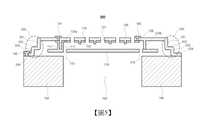
在下文中,將參考附圖詳細地描述本發明之實施例。圖3為展示根據本發明之第一實施例的MEMS聲學感測器(100)之組態的橫截面圖。Hereinafter, embodiments of the present invention will be described in detail with reference to the accompanying drawings. 3 is a cross-sectional view showing the configuration of the MEMS acoustic sensor (100) according to the first embodiment of the present invention.
MEMS聲學感測器(100)可藉由包含基板(160)、背板(120)、電極(130)、錨定器(123a、123b)、隔膜(110)及應力釋放單元(150)而組態。The MEMS acoustic sensor (100) may be assembled by including a substrate (160), a backplate (120), electrodes (130), anchors (123a, 123b), a diaphragm (110) and a stress relief unit (150). state.
基板(160)可由矽材料製成,且在中心包含空腔(165)。因此,自外部引入之聲波穿過空腔(65)並對隔膜(110)施加外力,使得具有彈性之隔膜(110)可在藉由聲波而變形的同時振動。當藉由聲波在垂直於隔膜(110)之方向(垂直於由隔膜形成之平面的方向)上發生位移時,電容歸因於隔膜(110)與背板(120)之間的間隙變化而變化。The substrate (160) may be made of silicon material and includes a cavity (165) in the center. Therefore, the sound waves introduced from the outside pass through the cavity ( 65 ) and apply an external force to the diaphragm ( 110 ), so that the diaphragm ( 110 ) having elasticity can vibrate while being deformed by the sound waves. When displaced by sound waves in the direction perpendicular to the diaphragm (110) (the direction perpendicular to the plane formed by the diaphragm), the capacitance changes due to the change in the gap between the diaphragm (110) and the back plate (120) .
背板(120)支撐於基板(160)上且包含向上連通之複數個通孔(121)。朝向基板(160)突起之至少一個錨定器(123a、123b)形成於背板(120)之內表面上。在圖3中,隔膜(110)由形成於背板(120)上之錨定器(123a、123b)支撐,且不與基板(160)進行接觸。因此,無關於空腔(165)之位置及尺寸,錨定器(123a、123b)之位置可自由地配置於背板(120)上。The backplane (120) is supported on the base plate (160) and includes a plurality of through holes (121) communicating upward. At least one anchor (123a, 123b) protruding towards the base plate (160) is formed on the inner surface of the back plate (120). In Figure 3, the membrane (110) is supported by anchors (123a, 123b) formed on the backing plate (120) and is not in contact with the substrate (160). Therefore, regardless of the position and size of the cavity (165), the position of the anchors (123a, 123b) can be freely configured on the back plate (120).
電極(130)可安置於背板(120)之內表面上之複數個部位處。因此,可量測移動隔膜(110)與固定背板(120)之間的電容。Electrodes (130) may be placed at a plurality of locations on the inner surface of the backplate (120). Therefore, the capacitance between the moving diaphragm (110) and the fixed backplane (120) can be measured.
隔膜(110)由至少一個錨定器(123a、123b)支撐,且可藉由自外部通過空腔(165)引入之聲波而變形。隔膜(110)可由例如具有圓形或矩形形狀之多晶矽材料製成。然而,隔膜(110)之形狀或材料並不限於此且可以任何必要方式變化。另外,隔膜(110)與錨定器(123a、123b)之間的耦接可藉由隔膜(110)被直接或經由中間材料沈積於錨定器(123a、123b)上而達成。The diaphragm (110) is supported by at least one anchor (123a, 123b) and is deformable by sound waves introduced from the outside through the cavity (165). The diaphragm (110) may be made of polysilicon material, eg, having a circular or rectangular shape. However, the shape or material of the diaphragm (110) is not limited thereto and may be changed in any necessary manner. Additionally, the coupling between the membrane (110) and the anchors (123a, 123b) may be achieved by the membrane (110) being deposited on the anchors (123a, 123b) directly or through an intermediate material.
在圖1中,曝露於外部且電連接之複數個連接襯墊(141、143)設置於背板(120)之上表面上,且複數個連接襯墊(141、143)具有穿過背板(120)且延伸至MEMS聲學感測器(100)封裝之內部的結構。In FIG. 1 , a plurality of connection pads (141, 143) exposed to the outside and electrically connected are disposed on the upper surface of the backplane (120), and the plurality of connection pads (141, 143) have through the backplane (120) and extends to the structure inside the MEMS acoustic sensor (100) package.
複數個連接襯墊(141、143)可藉由包含電連接至隔膜(110)的第一連接襯墊(141)(可移動側連接襯墊)及電連接至安置於背板(120)之下表面上之電極(130)的第二連接襯墊(143)(固定側連接襯墊)而組態。另外,複數個連接襯墊(141、143)可進一步包含與基板(160)進行電接觸並曝露於外部之連接襯墊(145)。A plurality of connection pads (141, 143) can be electrically connected to a pad disposed on the back plate (120) by including a first connection pad (141) (movable side connection pad) electrically connected to the diaphragm (110) The second connection pad (143) (fixed side connection pad) of the electrode (130) on the lower surface is configured. In addition, the plurality of connection pads (141, 143) may further include a connection pad (145) which is in electrical contact with the substrate (160) and exposed to the outside.
具體言之,安置於背板(120)之下表面上的電極(130)與穿透背板(120)之第二接觸襯墊(143)進行電接觸。因此,電極(130)可藉由自第二連接襯墊(143)延伸之引線(未展示)連接至外部積體電路(未展示)。Specifically, the electrodes (130) disposed on the lower surface of the backplane (120) make electrical contact with the second contact pads (143) penetrating the backplane (120). Thus, the electrodes (130) can be connected to an external integrated circuit (not shown) by leads (not shown) extending from the second connection pads (143).
另外,隔膜(110)包含自隔膜(110)之上表面沿著至少一個錨定器(123a)向上延伸的延伸部(111),且可形成於如下結構中:其中錨定器(123a)容納於延伸部(111)中,亦即,錨定器(123a)可在延伸部(111)之縱向方向上裝配。經由此類組態,隔膜(110)之延伸部(111)與第一連接襯墊(141)可直接接觸,而隔膜(110)可由錨定器(123a)牢固地支撐。最終,隔膜(110)與第一連接襯墊(141)之間的電連接可藉由穿透背板(120)而形成。此提供以下優點:與橫向地引出引線之習知MEMS聲學感測器相比,可改良封裝之設計自由度及其中之空間效率。Additionally, the septum (110) includes an extension (111) extending upwardly from the upper surface of the septum (110) along at least one anchor (123a), and may be formed in a structure wherein the anchor (123a) accommodates In the extension (111), that is, the anchor (123a) can be fitted in the longitudinal direction of the extension (111). Through such a configuration, the extension (111) of the diaphragm (110) and the first connection pad (141) can be in direct contact, and the diaphragm (110) can be firmly supported by the anchor (123a). Finally, the electrical connection between the diaphragm (110) and the first connection pad (141) can be formed by penetrating the backplane (120). This provides the advantage of improving the design freedom of the package and the space efficiency therein compared to conventional MEMS acoustic sensors with laterally drawn leads.
以此方式,隔膜(110)可藉由自曝露於背板(120)之上表面之第一連接襯墊(141)延伸的引線(未展示)連接至外部積體電路。最終,積體電路可根據隔膜(110)之移動感測隔膜(110)與電極(130)之間的可變電容,並將其轉換成電信號(PDM或類比信號)。In this way, the diaphragm (110) can be connected to external integrated circuits by leads (not shown) extending from the first connection pads (141) exposed on the upper surface of the backplane (120). Finally, the integrated circuit can sense the variable capacitance between the diaphragm (110) and the electrode (130) according to the movement of the diaphragm (110), and convert it into an electrical signal (PDM or analog signal).
同時,應力釋放單元(150)經組態以自背板(120)之邊緣部分延伸以與基板(160)接觸,且根據其結構特性,即使在背板(120)中發生一定程度之變形,該應力釋放單元亦可因其自身彈性而釋放應力。為此目的,應力釋放單元(150)可具有等於或小於背板(120)之厚度的厚度。Meanwhile, the stress relief unit (150) is configured to extend from the edge portion of the backing plate (120) to be in contact with the substrate (160), and according to its structural characteristics, even if a certain degree of deformation occurs in the backing plate (120), The stress releasing unit can also release stress due to its own elasticity. For this purpose, the stress relief unit (150) may have a thickness equal to or less than that of the backing plate (120).
根據本發明之第一實施例的應力釋放單元(150)至少包含自背板(120)向下彎曲之支撐壁(151),及自支撐壁(151)向外彎曲以與基板(160)進行表面接觸之凸緣(153)。因而,藉由歸因於背板(120)、支撐壁(151)與凸緣(153)之間的相互彎曲結構而具有一定程度之彈性,有可能在背板(120)及基板(160)之組裝之後釋放根據變形而不可避免地出現的應力。參看圖3,繪示了儘管隔膜(110)延伸至錨定器(123a、123b)之外部,但電極未形成於延伸部分中以免干擾應力釋放。The stress relief unit (150) according to the first embodiment of the present invention at least comprises a supporting wall (151) bent downward from the back plate (120), and is bent outwardly from the supporting wall (151) to communicate with the base plate (160). Surface contact flange (153). Therefore, by having a certain degree of elasticity due to the mutual bending structure between the back plate ( 120 ), the support wall ( 151 ) and the flange ( 153 ), it is possible for the back plate ( 120 ) and the base plate ( 160 ) to have a certain degree of elasticity. After assembly, the stress that inevitably occurs due to deformation is relieved. Referring to Figure 3, it is shown that although the diaphragm (110) extends outside the anchors (123a, 123b), electrodes are not formed in the extension so as not to interfere with stress relief.
另外,向下突起之凸塊(125)可設置於背板(130)之內表面上,且電極(130)可以被凸塊(125)穿透之形式插入。In addition, the protrusions (125) protruding downward can be disposed on the inner surface of the back plate (130), and the electrodes (130) can be inserted in the form of being penetrated by the protrusions (125).
圖4為展示根據本發明之第二實施例的MEMS聲學感測器之組態的橫截面圖。4 is a cross-sectional view showing a configuration of a MEMS acoustic sensor according to a second embodiment of the present invention.
在第二實施例中,除了支撐壁(151)及凸緣(152)之外,應力釋放單元(150)亦進一步包含在背板(120)與支撐壁(151)之間向內面向隔膜(110)之凹口(153)。此類凹口(153)促進應力釋放單元(150)之彈性變形,藉此幫助更容易發生應力釋放。除了凹口(153)之外的組態與第一實施例之組態相同,且因此將省略冗餘描述。In the second embodiment, in addition to the support wall (151) and the flange (152), the stress relief unit (150) is further included between the back plate (120) and the support wall (151) facing the diaphragm (150) inwardly. 110) of the notch (153). Such notches (153) facilitate elastic deformation of the stress relief unit (150), thereby helping stress relief to occur more easily. The configuration other than the notch ( 153 ) is the same as that of the first embodiment, and thus redundant description will be omitted.
圖5為展示根據本發明之第三實施例的MEMS聲學感測器之組態的橫截面圖。5 is a cross-sectional view showing a configuration of a MEMS acoustic sensor according to a third embodiment of the present invention.
根據第三實施例,應力釋放單元(350)包含自背板(120)之邊緣向下彎曲之第一支撐壁(351)、自第一支撐壁(351)向外延伸且平行於基板(160)而彎曲之第一凸緣(352)、自第一凸緣(352)向下彎曲之第二支撐壁(353),及自第二支撐壁(353)向外彎曲且與基板(160)進行表面接觸之第二凸緣(354)。因此,若根據第一實施例之應力釋放單元(150)具有一次彎曲結構,則根據第三實施例之應力釋放單元(350)可被視為具有二次彎曲結構。然而,其並不限於此,且有可能使用三次或更多次之彎曲結構以用於應力釋放。除了應力釋放單元(350)之外的組態與第一實施例之組態相同,且因此將省略冗餘描述。According to the third embodiment, the stress relief unit ( 350 ) comprises a first support wall ( 351 ) bent downward from the edge of the back plate ( 120 ), extending outward from the first support wall ( 351 ) and parallel to the base plate ( 160 ) ) and bend a first flange (352), a second support wall (353) bent downward from the first flange (352), and a second support wall (353) bent outwards and connected to the base plate (160) A second flange (354) for surface contact. Therefore, if the stress relief unit ( 150 ) according to the first embodiment has a primary bending structure, the stress relief unit ( 350 ) according to the third embodiment can be regarded as having a secondary bending structure. However, it is not limited to this, and it is possible to use three or more bending structures for stress relief. The configuration other than the stress relief unit ( 350 ) is the same as that of the first embodiment, and thus redundant description will be omitted.
圖6a為展示根據本發明之第四實施例的MEMS聲學感測器之組態的橫截面圖,圖6b為根據本發明之第四實施例的自上方檢視的平面圖,其中背板自MEMS聲學感測器移除,且圖6c為自上方檢視的根據本發明之第四實施例的MEMS聲學感測器的平面圖。6a is a cross-sectional view showing the configuration of a MEMS acoustic sensor according to a fourth embodiment of the present invention, and FIG. 6b is a plan view viewed from above according to a fourth embodiment of the present invention, wherein the backplate is from the MEMS acoustic sensor The sensor is removed and FIG. 6c is a plan view of a MEMS acoustic sensor according to a fourth embodiment of the present invention viewed from above.
與第一至第三實施例不同,第四實施例具有隔膜(110)係由複數個彈性支撐件(90:90a至90d)支撐之結構,而非隔膜(110)係由錨定器支撐之結構。因此,為了彈性地支撐隔膜(110),在由隔膜(110)形成之平面方向上設置用於在隔膜(110)與基板(160)兩者之間進行連接的彈性支撐件(90)。此類彈性支撐件(90)可被組態為具有鋸齒形摺疊形狀之MEMS彈簧,但並不限於此。Different from the first to third embodiments, the fourth embodiment has a structure in which the diaphragm (110) is supported by a plurality of elastic supports (90: 90a to 90d), while the non-diaphragm (110) is supported by anchors. structure. Therefore, in order to elastically support the diaphragm (110), an elastic support (90) for connecting between the diaphragm (110) and the substrate (160) is provided in the plane direction formed by the diaphragm (110). Such an elastic support (90) may be configured as a MEMS spring having a zigzag folded shape, but is not limited thereto.
連接襯墊(141、143)形成於基板(160)上,此允許每一連接襯墊(141、143)經由引線(147、149)連接至隔膜(110)及背板(130)。詳言之,除了起到在隔膜(110)振動時提供彈性支撐件之作用之外,彈性支撐件(90)亦起到將隔膜(110)與引線(147)進行電連接之作用。因此,由於可在無單獨電連接結構之情況下達成自隔膜(110)至連接襯墊(141)之電連接,故可計算隔膜(110)與背板(130)之間的電容。Connection pads (141, 143) are formed on the substrate (160), which allows each connection pad (141, 143) to be connected to the diaphragm (110) and the backplane (130) via leads (147, 149). Specifically, in addition to the function of providing an elastic support member when the diaphragm (110) vibrates, the elastic support member (90) also functions to electrically connect the diaphragm (110) and the lead wire (147). Therefore, since the electrical connection from the diaphragm (110) to the connection pad (141) can be achieved without a separate electrical connection structure, the capacitance between the diaphragm (110) and the backplane (130) can be calculated.
上文已參考附圖描述本發明之實施例,但本領域中熟習此項技術者將理解,本發明可以其他特定形式實施而不改變其技術構思或基本特徵。因此,應理解,上文所描述之實施例在所有方面皆係說明性而非限制性的。The embodiments of the present invention have been described above with reference to the accompanying drawings, but those skilled in the art will appreciate that the present invention can be implemented in other specific forms without changing its technical concept or essential characteristics. Therefore, it should be understood that the embodiments described above are illustrative and non-restrictive in all respects.
1:基板 2:背板 3:隔膜 4:空腔 5:MEMS聲學感測器 6a:支撐結構 6b:支撐結構 43:隔膜 48:背板 49:電極 53:引線 57:引線 58:可移動側電極襯墊 59:固定側電極襯墊 90:彈性支撐件 90a:彈性支撐件 90b:彈性支撐件 90c:彈性支撐件 90d:彈性支撐件 100:MEMS聲學感測器 110:隔膜 111:延伸部 120:背板 121:通孔 123a:錨定器 123b:錨定器 125:凸塊 130:電極 141:接觸襯墊 143:接觸襯墊 145:接觸襯墊 147:引線 149:引線 150:應力釋放單元 151:支撐壁 152:凸緣 153:凹口 160:基板 165:空腔 200:MEMS聲學感測器 300:MEMS聲學感測器 350:應力釋放單元 351:支撐壁 352:凸緣 353:支撐壁 354:凸緣 400:MEMS聲學感測器1: Substrate 2: Backplane 3: Diaphragm 4: Cavity 5:
圖1為展示習知MEMS聲學感測器之操作的模擬圖。 圖2為展示習知MEMS聲學感測器之特定組態的橫截面圖。 圖3為展示根據本發明之第一實施例的MEMS聲學感測器之組態的橫截面圖。 圖4為展示根據本發明之第二實施例的MEMS聲學感測器之組態的橫截面圖。 圖5為展示根據本發明之第三實施例的MEMS聲學感測器之組態的橫截面圖。 圖6a為展示根據本發明之第四實施例的MEMS聲學感測器之組態的橫截面圖。 圖6b為根據本發明之第四實施例的自上方檢視的平面圖,其中背板自MEMS聲學感測器移除。 圖6c為自上方檢視的根據本發明之第四實施例的MEMS聲學感測器的平面圖。FIG. 1 is a simulation diagram showing the operation of a conventional MEMS acoustic sensor. 2 is a cross-sectional view showing a specific configuration of a conventional MEMS acoustic sensor. 3 is a cross-sectional view showing the configuration of the MEMS acoustic sensor according to the first embodiment of the present invention. 4 is a cross-sectional view showing a configuration of a MEMS acoustic sensor according to a second embodiment of the present invention. 5 is a cross-sectional view showing a configuration of a MEMS acoustic sensor according to a third embodiment of the present invention. 6a is a cross-sectional view showing the configuration of a MEMS acoustic sensor according to a fourth embodiment of the present invention. 6b is a plan view from above with the backplate removed from the MEMS acoustic sensor according to a fourth embodiment of the present invention. Figure 6c is a plan view of a MEMS acoustic sensor according to a fourth embodiment of the present invention viewed from above.
100:MEMS聲學感測器100: MEMS Acoustic Sensors
110:隔膜110: Diaphragm
111:延伸部111: Extensions
120:背板120: Backplane
121:通孔121: Through hole
123a:錨定器123a: Anchor
123b:錨定器123b: Anchor
125:凸塊125: bump
130:電極130: Electrodes
141:接觸襯墊141: Contact pad
143:接觸襯墊143: Contact pad
145:接觸襯墊145: Contact pad
150:應力釋放單元150: Stress Relief Unit
151:支撐壁151: Support Wall
152:凸緣152: Flange
160:基板160: Substrate
165:空腔165: cavity
Claims (9)
Translated fromChineseApplications Claiming Priority (2)
| Application Number | Priority Date | Filing Date | Title |
|---|---|---|---|
| KR1020210001715AKR102544661B1 (en) | 2021-01-07 | 2021-01-07 | MEMS acoustic sensor |
| KR10-2021-0001715 | 2021-01-07 |
Publications (1)
| Publication Number | Publication Date |
|---|---|
| TW202227357Atrue TW202227357A (en) | 2022-07-16 |
Family
ID=82218905
Family Applications (1)
| Application Number | Title | Priority Date | Filing Date |
|---|---|---|---|
| TW110147041ATW202227357A (en) | 2021-01-07 | 2021-12-15 | Mems acoustic sensor |
Country Status (3)
| Country | Link |
|---|---|
| US (1) | US11910160B2 (en) |
| KR (1) | KR102544661B1 (en) |
| TW (1) | TW202227357A (en) |
Cited By (1)
| Publication number | Priority date | Publication date | Assignee | Title |
|---|---|---|---|---|
| TWI851332B (en)* | 2023-07-10 | 2024-08-01 | 星瑞半導體股份有限公司 | Micro-electro-mechanical system device |
Families Citing this family (2)
| Publication number | Priority date | Publication date | Assignee | Title |
|---|---|---|---|---|
| CN115334434B (en)* | 2022-10-13 | 2022-12-20 | 苏州敏芯微电子技术股份有限公司 | Microphone assembly and electronic equipment |
| CN116074714A (en)* | 2023-01-31 | 2023-05-05 | 歌尔微电子股份有限公司 | Electronic device and electronic apparatus |
Family Cites Families (8)
| Publication number | Priority date | Publication date | Assignee | Title |
|---|---|---|---|---|
| JP4947220B2 (en)* | 2010-05-13 | 2012-06-06 | オムロン株式会社 | Acoustic sensor and microphone |
| JP5338825B2 (en) | 2011-02-23 | 2013-11-13 | オムロン株式会社 | Acoustic sensor and microphone |
| KR101312495B1 (en) | 2012-12-24 | 2013-10-01 | 주식회사 디에스이엔티 | Rotation apparayus for printed circuit board auto clamp basket loader and unloader |
| KR20150047046A (en)* | 2013-10-23 | 2015-05-04 | 삼성전기주식회사 | Acoustic transducer and package module |
| KR101578542B1 (en)* | 2014-11-04 | 2015-12-18 | 주식회사 평화이엔지 | Method of Manufacturing Microphone |
| KR101807071B1 (en)* | 2016-10-06 | 2017-12-08 | 현대자동차 주식회사 | Microphone and manufacturing method thereof |
| KR102082716B1 (en)* | 2018-06-01 | 2020-02-28 | 주식회사 신성씨앤티 | MEMS acoustic sensor |
| US10993043B2 (en)* | 2019-09-09 | 2021-04-27 | Shin Sung C&T Co., Ltd. | MEMS acoustic sensor |
- 2021
- 2021-01-07KRKR1020210001715Apatent/KR102544661B1/enactiveActive
- 2021-12-14USUS17/550,716patent/US11910160B2/enactiveActive
- 2021-12-15TWTW110147041Apatent/TW202227357A/enunknown
Cited By (1)
| Publication number | Priority date | Publication date | Assignee | Title |
|---|---|---|---|---|
| TWI851332B (en)* | 2023-07-10 | 2024-08-01 | 星瑞半導體股份有限公司 | Micro-electro-mechanical system device |
Also Published As
| Publication number | Publication date |
|---|---|
| KR102544661B1 (en) | 2023-06-20 |
| US11910160B2 (en) | 2024-02-20 |
| US20220217473A1 (en) | 2022-07-07 |
| KR20220099620A (en) | 2022-07-14 |
Similar Documents
| Publication | Publication Date | Title |
|---|---|---|
| TW202227357A (en) | Mems acoustic sensor | |
| US20150041930A1 (en) | Acoustic transducer | |
| US10433068B2 (en) | MEMS acoustic transducer with combfingered electrodes and corresponding manufacturing process | |
| CN210609708U (en) | MEMS microphones and electronics | |
| CN110574397B (en) | MEMS sound sensor, MEMS microphone and electronic equipment | |
| US20120091546A1 (en) | Microphone | |
| US8436435B2 (en) | MEMS capacitive microphone | |
| US10993043B2 (en) | MEMS acoustic sensor | |
| CN103716743B (en) | Mems microphone | |
| CN104427450A (en) | MEMS microphone device with multi-level sensitivity output and its circuit | |
| US20120027235A1 (en) | Mems capacitive microphone | |
| CN115474144B (en) | MEMS Microphone | |
| CN114513731A (en) | A microphone assembly and electronic equipment | |
| KR101776752B1 (en) | Microphone | |
| US20250250157A1 (en) | Mems transducer | |
| JP5215871B2 (en) | Capacitor microphone diaphragm support device | |
| CN114885264A (en) | Microphone assembly and electronic equipment | |
| TWI747102B (en) | Structure of micro-electro-mechanical-system microphone | |
| KR101417018B1 (en) | Microphone and method for manufacturing the same | |
| US20150139467A1 (en) | Acoustic device and microphone package including the same | |
| JP2011244448A (en) | Micro-electro-machine capacitor microphone | |
| CN214281654U (en) | MEMS microphone and MEMS structure thereof | |
| CN114390418A (en) | MEMS electrode formation method | |
| KR101816253B1 (en) | Voice transmitting device and manufacturing method thereof | |
| KR101610173B1 (en) | Microphone system and control method of microphone |